ML725J16F中文资料
XRE-200系列电动机保护测控装置说明书-V3.3-20140604

修订记录
日期
2014-05-14
修订版
增加区域保护逻辑
描述
封面增加公司文件控制标签
作者
王宝锋
2014-05-16 V1.10 2014-06-04
修改装置接线端子定义 定值按保护型号定义 合位 系统定值的“操作回路选择”控制字决定
王宝锋
保护逻辑中的跳、合位使用 DSP 开入的跳、 王宝锋
西安西瑞保护控制设备有限责任公司
版权所有:西安西瑞保护控制设备有限责任公司 本说明书适用于 XRE-200 系列电动机保护测控装置(V3.3)版本程序。 本说明书和产品今后可能会有小的改动,请注意核对实际产品与说明书的版本是否相符。 更多产品信息,请访问:。 商务电话:029-68590758 技术支持电话:029-68590751 传真:029-68590758
西安西瑞保护控制设备有限责任公司
文件编号:OST/XR 3005 第 1 页 共 66 页 版本:V3.3
文件名称
XRE-200 系列电动机保护测控装置说明书
XRE-200 系列 电动机保护测控装置( V3.3)说明书
编制: 校核: 审定:
西安西瑞保护控制设备有限责任公司
XRE-200 系列 电动机保护测控装置( V3.3) 说明书
目
录
1 适用范围及特性........................................................................................................................... 1 1.1 适用范围............................................................................................................................... 1 1.2 主要特性............................................................................................................................... 1 1.3 型号及功能配置 .................................................................................................................... 2 2 技术参数 ..................................................................................................................................... 3 2.1 机械及环境参数 .................................................................................................................... 3 2.2 额定电气参数........................................................................................................................ 3 2.3 过载能力............................................................................................................................... 3 2.4 功率消耗............................................................................................................................... 3 2.5 机械性能............................................................................................................................... 3 2.6 电气绝缘性能........................................................................................................................ 3 2.7 电磁兼容性能........................................................................................................................ 4 2.8 输出接点容量........................................................................................................................ 4 2.9 通信接口............................................................................................................................... 4 2.10 故障记录 ............................................................................................................................. 5 2.11 主要技术指标 ...................................................................................................................... 5 3 保护工作原理 .............................................................................................................................. 9 3.1 差动保护............................................................................................................................... 9 3.2 电流速断保护.......................................................................................................................12 3.3 3.4 3.5 3.6 负序电流保护.......................................................................................................................12 零序电流保护(不接地) .....................................................................................................13 零序电流保护(接地).........................................................................................................14 堵转保护..............................................................................................................................14
电源箱产品说明书
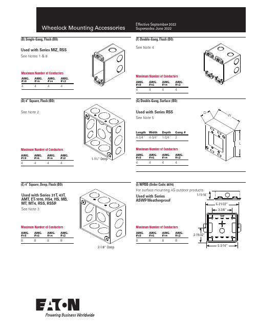
(B) Single-Gang, Flush (BO)(D) 4” Square, Flush (BO)(E) 4” Square, Deep, Flush (BO)Used with Series MIZ, RSSSee Notes 1 & 8Maximum Number of ConductorsAWG. #18AWG. #16AWG. #14AWG. #124444See Note 2Maximum Number of ConductorsAWG. #18AWG. #16AWG. #14AWG. #124444Used with Series 31T , 43T , AMT , ET -1010, HS4, HS, MB, MT , MT4, RSS, RSSP See Note 3Maximum Number of ConductorsAWG. #18AWG. #16AWG. #14AWG. #128888(I) WPBB (Order Code: 9014)(G) Double-Gang, Surface (BO)(F) Double-Gang, Flush (BO)Maximum Number of ConductorsAWG. #18AWG. #16AWG. #14AWG. #124444See Note 4Used with Series RSS See Note 5Maximum Number of ConductorsAWG. #18AWG. #16AWG. #14AWG. #124444Length Width Depth Gang #4-3/4”4-3/4”1-3/4”2Used with Series ASWP WeatherproofMaximum Number of ConductorsAWG. #18AWG. #16AWG. #14AWG. #128888Mounting Accessories(J) BB Backbox (Order Codes: Red 2830, Gray 2349)(M) IOB Backbox (Order Codes: Red 5046, White 5047)For surface mounting MT products(Q) 4” Square Deep w/ Extension Ring, Flush (BO)(N) DBB Backbox (Order Code: 2955)Used with Series CH70, CH90, E70, ET70, E90, ET90, ET -1080 See Note 6Exterior Ring Depth1-1/2”2-1/8”AWG. #1888AWG. #1688AWG. #1488AWG. #1248Standard steel backbox with knockouts for interior surface mounting, concealed conduit mounting or semi-flush applications. It is painted Sturdy die-cast housing, threaded conduit hole and knockout for outdoor applications. It is painted to match the ed with Series AMT E70, ET70, HS4, HS, MTFor surface mounting speakers, chimes, and electronic applications2-1/8” DeepStandard steel backbox provided with knockouts for interior surface mounting, concealed conduit mounting or semi-flush applications. Knockouts for 1/2” conduit(each side)Mounting AccessoriesUsed with Series RSSWP WeatherproofMaximum Number of ConductorsAWG. #18AWG. #16AWG. #14AWG. #128888Used with Series CH70, CH90, E70, ET70, E90, ET90, ET -1080(Y) SER-R Square Semi-Flush Extension Ring (Order Codes: Red 3045, White 3049)(X) SHBB Square, Surface Backbox (Order Codes: Red 7254, White 7255)(W) 4-11/16” Square, Deep Surface (BO)Maximum Number of ConductorsAWG. #18AWG. #16AWG. #14AWG. #1210101010RSSUsed with Series CH70, E70, ET70Used with Series DSMSee Note 7”(V) SSB-4 Ceiling Support Bridge (Order Code: 3380)Provisions for (4) J-nuts #8-32 ib 3-3/8” square. Material: Steel Used with Series CH70, CH90, E70, ET70, E90, ET90, ET -1080, and Eluxa ELFHNC, ELFHSC, ELHNC, ELHSC, ELSPKC, ELSPSTC, ELSTCMounting Accessories(Z) SBL-2 Backbox (Order Codes: Red 6988, White 6989)(AA) E50SB-R (Order Codes: Red 0230, White 0231)(BB) E50SSB-R (Order Codes: Red 0232, White 0233)(CC) SSB-8 8” Ceiling Support Bridge (Order Code: 3573)(EE) E60 Extension Ring (Order Code: Red 3758, White 3757)(DD) CBB-8 8” Ceiling Speaker Backbox (Order Code: 3314)Used with Series E50Used with Series E505.03”Used with Series RSSPUsed with Series S 8” Ceiling Speakers1.033” 7.325 + 13”D/S0.953”4.833”ø7.825(GG) WFP Plate (Order Codes: Red 4696, White 4697)Mounting Accessories (HH) WFPA Plate (Order Codes: Red 4696, White 4697)Used with Exceder ST, HS, HN (LL) LSBB Backbox (Order Codes: Red 2402, White 2403) (KK) ESB-KIT (Order Codes: Red 0533, White 0534) (JJ) ESBC Backbox (Order Codes: Red 2751, White 2752) Used with Exceder LST, LHS,Used with Exceder LST, LHS, LHNMaximum Number of ConductorsAWG.#18AWG.#16AWG.#14#124444(II) ESB Backbox (Order Codes: Red 2749, White 2750)For indoor surface mounting of Exceder productsUsed with Exceder STC, HSC,For indoor surface mounting of Exceder productsTrim Plate Kit for Exceder LEDNote:gang device ring to the single gang trim plate.(MM) OSB(NN) LSPKBB Backbox (Order Codes: Red 0756, White 0757)Maximum Number of ConductorsAWG. #18AWG. #16AWG. #14AWG. #124444Used with Exceder LSPK, LSPSTFor indoor surface mounting of Exceder LED Speaker productsUsed with ET1080*Refer to specification sheet S7000 for mounting option details.(OO) LSPKBB-C Backbox (Order Codes: Red 0927, White 1003)Maximum Number of ConductorsAWG. #18AWG. #16AWG. #14AWG. #124444Used with Exceder LED Ceiling LSTC, LHSC, LHNC, LSPKC, LSPSTC and Eluxa Ceiling - ELSTC, ELHSC, ELHNC, ELSPKC, ELSPSTC, ELFHNC, ELFHSC(PP) LFTP Trim Plate Kit (Order Codes: Red 1112, White 2113)Included with Exceder LED Low Frequency Sounders (LFHNK, LFHSK)1. F igure B is typical of a Steel City LXM-WOW box or equal.Figure B should be a 3.5” deep backbox for conduitinstallations and is typical of a Steel City CY -1/2 box or equal.2. F igure D is typical of a Steel City 52151 box or equal.3. F igure E is typical of a Steel City 52171 box or equal.4. F igure F is typical of two Steel City LXM-WOW boxesor equal.5. F igure G is typical of a Wiremold 5748-2 box or equal.6. F igure Q is typical of a Steel City 52171 box with a Steel City53151 extension ring or equal.7. F igure W is typical of a Steel City 72171-1 box or equal.8. U se 3.5” deep backbox on all MIZ products when EMTconduit is used.9. W hen used with AC Horn (J), “BB” must be used for surfacemount.10. H S4, HS, MT or MTWP Strobe are for outdoor mounting.11. U se with Series RSSP .12. F igure U is typical of a RANDL Industries backbox. (“TotalNumber of conductors shall be in accordance with NEC table 314.16 (B)”).(QQ) ELSBB Backbox (Order Codes: Red 110752, White 110753)Maximum Number of ConductorsAWG. #18AWG. #16AWG. #14AWG. #124444Used with Eluxa ELHN, ELHS, ELSTFor indoor surface mounting of Eluxa horns, horn strobes and strobes (wall models)Used with Eluxa ELSPK, ELSPST , ELFHN, ELFHS(RR) ELSPKBB Backbox (Order Codes: Red 110754, White 110755)Maximum Number of ConductorsAWG. #18AWG. #16AWG. #14AWG. #124444For indoor surface mounting of Eluxa speaker and low frequencysounder wall productsMounting MatrixS e r i e s E 90/E T 90S e r i e s R S S /R S S RS e r i e s R S S PS e r i e s 31TS e r i e s E 50S e r i e s 43T B e l l sS e r e i s C HS e r i e s E T 80S e r i e s E T 1010S e r i e s M B M o t o r B e l l sS e r i e s E 70/E T 70S e r i e s E 60S e r i e s M I Z /M I Z -T CS e r i e s M TS e r i e s H S 4/H SS e r i e s S M /D S MS e r i e s A M TS e r i e s R S S W P (1), A S W P (2), A H W P (3), M T W P (4), M T -12/24(4), E T 70W P (4)S e r i e s S 8E x c e d e r - S T C , H S C , H N CE x c e d e r - S T , H S , H NE l u x a E L H N , E L H S , E L S TE l u x a E L S P K , E L S P S T , E LF H N , E L F H S E l u x a E L S P K C , E L S P S T C , E L F H N C E L F H S C , E L H N C , E L H S C , E L S T C(A) Universal Mounting Plate Mounting AccessoriesBackbox Mounting Heights for Wheelock Wall-Mounted Horizontal Strobe AppliancesNFPA-72 (2002)7.5.4* Appliance Location. Wall-mounted appliances shall be mounted such that the entire lens is not less than 2.0 m (80 in.) and not greater than 2.4 m (96 in.) above the finished floor.RSSP FlushSurface Retrofit Exceder ST , HS, HNRSS Strobe MT and AMT Multitone Strobe Eluxa ELHN, ELHS, ELST Eluxa ELSPK, ELSPST , ELFHN, ELFHS Backbox Mounting Options*80 In.80 In.6 In.80 In.6 In.80 In.6 In.80 In.6 In.80 In.6 In.(B) 1-Gang x 2” Deep - Flush (BO)80 3/4 5 1/479 1/8 6 7/880 5/16 5 11/16(D) 4” x 4” x 1.5” Deep - Flush (BO)83 15/1680 1/4 5 3/478 5/87 3/877 1/88 1/881 1/8 4 7/8(E) 4” x 4” x 2.125” Deep - Flush (BO)83 15/1680 1/4 5 3/478 5/87 3/877 7/88 1/881 1/8 4 7/8(F) 2-Gang x 3.5” Deep - Flush (BO)80 3/4 5 3/479 1/8 6 7/878 3/87 5/8(G) 2-Gang x 1.75” Deep - Surface (BO)79 7/8 6 1/878 1/47 3/477 1/28 1/2(M) IOB Surface & Weatherproof (WSI)77 1/48 3/4(P) SBB Surface (WSI)77 1/88 7/8(Q) 4” x 4” x 2.125” Box w/ 1.5” Extension Ring - Flush (BO)83 15/1680 1/4 5 3/478 5/87 3/877 7/88 1/8(U) 5” Square Backbox w/ Extension Ring, Flush (BO)83 7/1678 1/87 7/877 3/88 5/8(X) SHBB (WSI) Shallow Surface78 1/87 7/8(Y) 4” x 4” x 1.5” Box w/ 1.5” Extension Ring Plate (BO)(Z) SBL -2 Surface (WSI)80 1/2(II) ESB Backbox 5.375” x 4.75” x 2.0625”79 9/166 7/16(QQ) ELSBB Backbox 4.8” x 2.76” x 1.98”79 3/865/8(RR) ELSPKBB Backbox 6.48” x 4.69” x 2.0”79 1/46 3/4Series CH70Chime StrobeSeries ET80Speaker Strobe Series E70Speaker Strobe Series ET70Speaker Strobe Series SA-70S Self Amplified Speaker Strobe Backbox Mounting Options*80 In.6 In.80 In.6 In.80 In.6 In.80 In.6 In.80 In.6 In.(P) SBB Surface (WSI)77 ¾8 ¼79 3/16 6 13/1677 ¾8 ¼77 ¾8 ¼79 3/16 6 13/16(Q) 4” x 4” x 2.125” Box w/ 1.5” Extension Ring - Flush (BO)77 ½7 ½80678 ½7 ½78 ½7 ½806(U) 5” Square Backbox w/ Extension Ring - Flush (BO)78779 ½5 ½78778779 ½5 ½(X) SHBB (WSI) Shallow Surface(Y) 4” x 4” x 1.5” Box w/ 1.5” Extension Ring Plate - Flush (BO)78 ½7 ½806* Measured from bottom of backbox (inches)ote: N (BO) = By Others; (WSI) = Wheelock ProductMounting NotesCaution: The mounting options figures show the maximum number of field wires (conductors) that can enter the backbox used with each mounting option.If these limits are exceeded, there may be insufficient space in the backbox to accommodate the field wires and stresses from the wires could damage the product. Although the limits shown for each mounting option comply with the National Electrical code (NEC), Wheelock recommends use of the largest back-box option and the use of approved stranded field wires whenever possible, to provide additional wiring room for easy installation and minimum stress on the product from wiring.Caution: Check that the installed product will have sufficient clearance and wiring room prior to installing backboxes and conduit, especially if sheathed multi-conductor cable or 3/4” conduit fittings are used.1. Mounting hardware for each mounting option is supplied.2. Conduit entrances to the backbox should be selected to provide sufficient wiring clearance for the installed product. When extension rings are required, con-duit should enter through thebackbox, not the extension ring. Use Steel City #53151 (1-1/2” deep) or #53171 (2-1/8” deep) extension rings (as noted in the mounting options) or equal with the same cut-out area.3. When terminating field wires, do not use more lead length than required. Excess lead length could result in insufficient wiring space for the appliance.4. Use care and proper techniques to position the field wires in the backbox so that they use minimum space and produce minimum stress on the product. This is especially important for stiff,heavy gauge wires and wires with thick insulation or sheathing.5. Do not pass additional wires (used for other than the appliance) through the backbox “unless the backbox is of a sufficient size to permit additional wiring as described in NEC 314.16 (B)”.Such additional wires could result in insufficient wiring space for the appliance.ote: N Due to continuous development of our products, specifications and offerings are subject to change without notice in accordance with Eaton standard terms and conditions.© 2022 EatonAll Rights Reserved Printed in USAPublication No. TD450028EN September 2022Eaton is a registered trademark.All other trademarks are property of their respective owners.Eaton1000 Eaton Boulevard Cleveland, OH 44122United States Life safety & mss notification solutions 273 Branchport Ave.Long Branch, NJ 07740Eaton.oom/LifesafetynotificationMounting AccessoriesTechnical Data TD450028ENEffective June 2022。
雅马哈四冲程船外机技术规格表
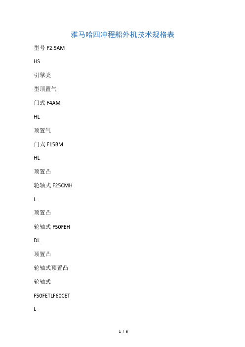
雅马哈四冲程船外机技术规格表型号F2.5AMHS引擎类型顶置气门式F4AMHL顶置气门式F15BMHL顶置凸轮轴式F25CMHL顶置凸轮轴式F50FEHDL顶置凸轮轴式顶置凸轮轴式F50FETLF60CETL顶置凸轮轴式F80BETL4气门双顶置凸轮轴式气缸数11224444F100BETL4气门双顶置凸轮轴式4F115AETX4气门双顶置凸轮轴式4F150AETX4气门双顶置凸轮轴式4F200BETX4气门双顶置凸轮轴式6F225AETX4气门双顶置凸轮轴式6F250AETX4气门双顶置凸轮轴式6缸径54*31.559*4159*5965*7563*7563*7565*7579*81.479*81.479*88.894*96.294*80. 594*80.594*80.5(MM*MM)排气量(CM3)螺旋浆最大输出1.8KW(2.5HP)2.9KW(4HP)11KW(15HP)18.5KW(25HP)38.8KW(50HP)36.8KW(50HP)44.1KW(60HP)58.8KW(80HP)73.6KW(100HP)84.6KW(115HP)110.3KW(150HP)147.1KE(2 00HP)165.5KW(225HP)721123234989969969961596159617412670335233523352183.9KW(250HP)最大转速(RPM)最大燃料消费(1/H)1.11.649.220202028343855.86670815250~57504000~50004500~55005000~60005000~60005000~60005000~60005000~60005000~60005000~60005000~60005000~60005000~60005000~600 0点火系统齿轮比TCL晶体管2.08(27/13)TCL晶体管2.08(27/13)562CDI(微电脑)2.08(27/13)567CDI(微电脑)2.08(27/13)550TCL(微电脑)1.85(24/13)527TCL(微电脑)1.85(24/13)527TCL(微电脑)1.85(24/13)527TCL(微电脑)2.31(30/13)536CDI(微电脑)2.15(28/13)536TCL(微电脑) 2.15(28/13)516TCL(微电脑) 2.0(28/14)643TCL(微电脑) 2.0(30/15)643TCL(微电脑) 2.0(30/15)643TCL(微电脑) 2.0(30/15)643推荐舰板高度(MM)重量43217内0.9L置22内1.1L手起动后操置4512L手起动后操6524L手起动后操11124L电起动后操11124L电起动前操11124L电起动前操17224L电起动前操18424L电起动前操18824L电起动前操21626924L电起动前操269278(KG)燃油箱/电起动前操/电起动前操/电起动前操规格手起动后操。
09.美的中央空调控制器产品介绍(2017)

强劲送风:调高风机运转频率,达到快速制冷/制热目的
RM02A/BGS 双热源专用遥控器
无地址设定功能
26℃一键设定:制冷模式下可实现,显示环保标志 省电模式:降低风机运转频率,实现省电效果(除湿/送风模式无效) 数显功能:可关闭室内机显示模块的区域,避免灯光影响休息 模式锁定:长按调整键5秒即可锁定
定时设定:可设定定时开关时间
KJR-90D/BK
以0.5h/次跳跃,定时达10h后以1h/次跳跃
替换KJR-90C/BY(A) 新款线控器
四周环境温度30℃,设定温度以-1℃/h
下调直至四周温度达到26℃)
组合锁定:同时按压“时钟”和“水平摆”按钮则 显示锁定图标,再次同时按压按钮锁定图标消失
第三部分:线控器简介
三、多联机线控器简介------KJR-90W/BK(新增)
运行模式:自动、制冷、制热、除湿、送风 风速设定: 七挡风模式(适用于直流电机)自动、低风、中 低风、中风、中高风、高风、超高风、强劲风 三挡风模式(适用于交流电机)自动、低风、中 风、高风 温度设定范围:17~30℃,温度调节精度±0.5 ℃/0.5S 摆风功能:适用于装有电动出风面板的室内机 导风条自动摆风状态,无角度控制功能,图标显 示15秒灯灭。 功能键:用于切换当前模式下可设置的功能,包 括:灯光功能、睡眠功能、ECO、电辅热设定、 随身感功能、定时设置等。 滤网清洗提示:记录设备运行时间,按时提醒清 洗滤网 可设置室内机通讯地址
第二部分:遥控器简介
二、遥控器简介------RM12D/BGF(新增)
运行模式:自动、制冷、制热、除湿、送风 风速设定:七挡风模式,自动、低风、中低风、 中风、中高风、高风、超高风、强劲风 温度设定范围:17~30℃,温度调节精度±0.5 ℃/0.5S 风向设定:五档风向设定 增加水平、垂直摇摆功能 电辅热设定:强制开启电辅热,强制关闭电辅热, 电辅热自动开 灯光设定:可控制室内机显示盒的显示/熄灭状态 及温度查询功能 睡眠功能:一键设定睡眠功能 经济运行模式:制冷:26℃,风速自动风;
iPACS-5700变电站综合自动化系统与装置说明书(上册)V1.04

iPACS-5000 变电站综合自动化系统
综
述
版本:V2.02
江苏金智科技股份有限公司
0 变电站综合自动化系统综述(V2.02)
目
录
1. 概述 .............................................................................................................................................................. 1 1.1. 适用范围 ................................................................................................................................................ 1 1.2. 系统特点 ................................................................................................................................................ 1 2. 系统组成....................................................................................................................................................... 2 2.1. 变电站综合自动化系统典型结构 ..............................................
产品型号编制规则

1.3.12排放实现方式代号 是指实现国家规定的汽车排放所采用的方式,用一位阿拉伯数字表示 0——排放实现方式0 1——排放实现方式1 2——排放实现方式2 1.3.13货车驾驶室特征或客车类型代号 用于分别表述货车驾驶室特征或客车的类型,用一位大写字母表示,分述如下: 1.3.13.1 货车驾驶室特征代号 B─标准驾驶室(老车型代号为空) F─半高顶驾驶室 S─四开门驾驶室 V─高顶驾驶室 W─加长驾驶室
Y
Y
P>430
M
M N
N
P
注1:必须填写内控发动机功率代号。 注2:表中的公告发动机功率区间代号,列于此仅作对比。 注3:斯太尔原发动机功率(PS)代号由一位阿拉伯数字表示。扩展后的功率(PS)代号,列于此处可供参考。 0—400;1—450;2—310/336;3—410/420;4—240;5—210/220;6—260/266;7—270/290;8—320;9—360/371 。
表2 品牌与系列代号的组合
品牌 系列代 0系列 0(备用) 1 斯太尔牌 2 3 6 黄河牌 豪泺牌 4(1) 7 豪泺7产 品 豪运产 品(国 Ⅱ) N07系列 黄河将* 金刚系 少帅系* 军系列 列 列产品 豪泺7产 豪泺 品* 8*(日野 机) 1系列 2系列 3系列 4系列 5系列 6系列 7系列 8系列 9系列
表3 公告发动机功率区间(P)代号
功率 代号 B C D E F G H K 功率区间 kW 50<P≤66 66<P≤81 81<P≤96 96<P≤110 110<P≤125 125<P≤140 140<P≤165 165<P≤190 (PS) (68<P≤90) (90<P≤110) (110<P≤130) (130<P≤150) (150<P≤170) (170<P≤190) (190<P≤225) (225<P≤259) 功率 代号 M N S V W X Y 功率区间 kW 190<P≤220 220<P≤257 257<P≤293 293<P≤331 331<P≤375 375<P≤430 (PS) (259<P≤300) (300<P≤350) (350<P≤399) (399<P≤450) (450<P≤510) (510<P≤585) (P>585)
飞龙 wi
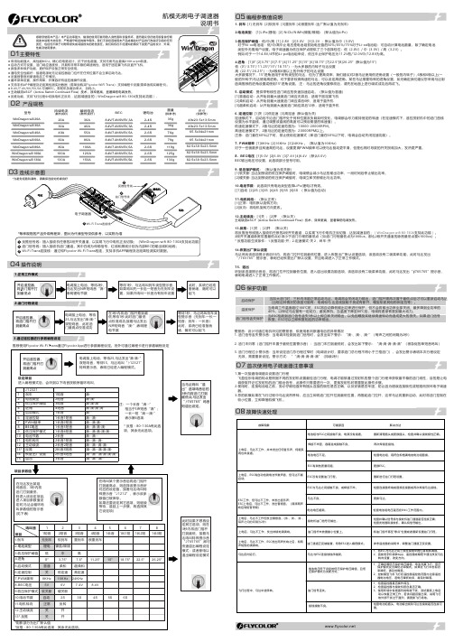
持续电流(散热良好)瞬间电流(散热良好)BEC尺寸(供参考)重量(供参考)20A 30A 40A 60A 30A 40A 55A 80A 锂电池型号79g 35g 36g 76g 49x23.5x13.5mm 65.5x34x21mm● 反推功能,支持飞行过程中切换电机正反向,达到减速目的(WinDragon wifi 80-130A 支持此功能)。
2-4S 2-4S 2-6S 2-6S 8.4V/7.4V/6V/5V ,5A 80A 100A 119g 2-6S 100A 120A 125g 2-6S 130A150A130g82.5x39.5x23.5mm2-6S航模无刷电子调速器WinDragon wifi 130AWinDragon wifi 100A WinDragon wifi 80A WinDragon wifi 60A WinDragon wifi 30A WinDragon wifi 40A WinDragon wifi 20A 8.4V/7.4V/6V/5V ,5A 8.4V/7.4V/6V/5V ,5A 8.4V/7.4V/6V/5V,5A8.4V/7.4V/6V/5V ,5A 82.5x39.5x23.5mm 82.5x39.5x23.5mm 65.5x34x21mm 49x23.5x13.5mm 02 产品规格04 操作说明1.正常工作模式2.油门行程设定3.通过遥控器进行参数编程设定推荐使用Flycolor Wi-Fi Trans 通过Flycolor App 进行参数编程设定。
另外可通过编程卡进行参数编程设定1. 刹车: [1] 无刹车 [2]软刹车 [3]重刹车 [4]很重刹车 (出厂默认值为无刹车)2.电池类型: [1]LiPo(锂电) [2] NiCb/NiMh(镍氢/镍隔) (默认值为Li Po )3.低压保护阈值:低/中/高 [1] 2.8V [2]3.0V [3]3.2V ;默认值为中(3.0V)对于Ni-xx电池组:低/中/高中止电压是电池组初始电压值的50%/65%/75%对于Li-xx电池组:可自动计算电池数量,除了确定电池 类型外无需用户设置。
FLUCK 725 中文说明书

725Ex
Multifunction Process Calibrator
用户手册
有限担保和有限责任
Fluke公司保证每一个产品在正常使用和维修期间都没有材料缺陷和制造工艺问题。担保期为从购买产品之日起的一年内。零件、产品修理和 服务的担保期为 90 天。 保证仅适用于授权零售商的原始买方或最终用户,本保证不适用于保险丝和消耗电池或者任何被 Fluke 公司确认为由于误用、改造、疏忽、意外、非正常操作和使用所造成的产品损坏。Fluke 公司保证软件能够在完全符合性能指标的条件 下至少操作90天,并且软件是正确地记录在无缺陷的媒体上。Fluke公司并不保证软件没有错误或不会操作中断。
本保证包括买方仅有的全部维修内容,并且已取代以其他方式明示或暗示的所有其他保证内容,包括但不限于为满足特殊适销性或要求所引起 的任何暗示的保证内容。Fluke公司不对任何特殊的、间接的、偶然的或后续的损坏或损失及数据丢失承担责任,无论是否由于任何理由或推 论而导致这些损失。
由于某些国家或州不承认暗示的保证条款限制、意外或后续损坏的限制和排除责任条款,本保证的限制和排除责任条款可能不适用于每一个买 方。如果本担保的某些任何条款被法院或其他拥有适当管辖权的决策者判定为无效或不得生效,则此类判决将不影响任何其他条款的有效性或
January 2005 (Simplified Chinese) Rev.1, 8/05
© 2005 Fluke Corporation, All rights reserved. All product names are trademarks of their respective companies.
i
725Ex 用户手册
利用回路电源测量电流 .............................................................................................. 19 测量电气参数(显示屏下部) ................................................................................... 21 测量温度.......................................................................................................................................................................................................................................... 1 联系 Fluke ...................................................................................................................... 1 标准设备......................................................................................................................... 3 安全须知......................................................................................................................... 3 危险禁制区 ..................................................................................................................... 3
产品尺寸及重量资料

MWD512VBNANA*4个内机ILLUSION(风冷风管机组系列)内机11004902500.521006 TWQ548AA0EAA ILLUSION(风冷风管机组系列)外机113046014500.751791MWD509VBNANA*2个内机ILLUSION(风冷风管机组系列)内机8004902500.20406 MWD518VBNANA ILLUSION(风冷风管机组系列)内机12104902500.15276 MWD524VBNANB ILLUSION(风冷风管机组系列)内机14606303000.28366 TWQ560AA0EAA ILLUSION(风冷风管机组系列)外机113046014500.751791MWD509VBNANA ILLUSION(风冷风管机组系列)内机8004902500.10206 MWD512VBNANA*3个内机ILLUSION(风冷风管机组系列)内机11004902500.39756 MWD518VBNANA ILLUSION(风冷风管机组系列)内机12104902500.15276 TWP563BA0EAA ILLUSION(风冷风管机组系列)外机113046014500.751791能量分配箱512*3HP ILLUSION(风冷风管机组系列)6704302700.08MWD509VBNANA ILLUSION(风冷风管机组系列)内机8004902500.10206 MWD512VBNANA*2个内机ILLUSION(风冷风管机组系列)内机11004902500.26506 MWD518VBNANA ILLUSION(风冷风管机组系列)内机12104902500.15276 TWQ551AA0EAA ILLUSION(风冷风管机组系列)外机113046014500.751791 MWD509VBNANB*2个内机ILLUSION(风冷风管机组系列)内机7406203000.28206 MWD518VBNANB*2个内机ILLUSION(风冷风管机组系列)内机11806303000.44366 TWQ554AA0EAA ILLUSION(风冷风管机组系列)外机113046014500.751791MWD509VBNBNA ILLUSION(风冷风管机组系列)内机7406203000.14226 MWD512VBNBNA*2个内机ILLUSION(风冷风管机组系列)内机11004902500.26506 MWD524VBNBNA ILLUSION(风冷风管机组系列)内机14606303000.28366 TWQ557AA0EAA ILLUSION(风冷风管机组系列)外机113046014500.751791 MCD540EBNDNA ILLUSION(风冷风管机组系列)内机19506202900.35536 TTK540AA0EAA ILLUSION(风冷风管机组系列)外机111045014000.701161MWD509EBCDNA ILLUSION(风冷风管机组系列)内机7506202900.1322.56 TWK509AA0EAA ILLUSION(风冷风管机组系列)外机8903406000.18364 MWD512EBDDNA ILLUSION(风冷风管机组系列)内机10506202900.1927.56 TWK512AA0EAA ILLUSION(风冷风管机组系列)外机8903406000.18434MWD518EBFDNA ILLUSION(风冷风管机组系列)内机11806202900.21306 TWK518AA0EAA ILLUSION(风冷风管机组系列)外机10203958500.3460.52 MWD524EBHDNA ILLUSION(风冷风管机组系列)内机14706202900.26366 TWK524AA0EAA ILLUSION(风冷风管机组系列)外机10904308900.42742MWD530EBHDNA ILLUSION(风冷风管机组系列)内机16306202900.29476 TWK530AA0EAA ILLUSION(风冷风管机组系列)外机10904308900.42902 MWD540AANBAA(含单排热水盘管)ILLUSION(风冷风管机组系列)内机12208303400.3449.56 TWK540AD0EAB ILLUSION(风冷风管机组系列)外机111045014000.701162MWD540EBKDNA ILLUSION(风冷风管机组系列)内机19506202900.35536 TWK540AD0EAA ILLUSION(风冷风管机组系列)外机111045014000.701162 2MWD509EBCDNA ILLUSION(风冷风管机组系列)内机7506202900.26456 TWD518AA0EAC ILLUSION(风冷风管机组系列)外机11204609300.4810022MWD512EBDDNA ILLUSION(风冷风管机组系列)内机10506202900.38556 TWD524AA0EAC ILLUSION(风冷风管机组系列)外机11204609300.481012 2MWD518EBFDNA ILLUSION(风冷风管机组系列)内机11806202900.42606 TWD536AA0EAC ILLUSION(风冷风管机组系列)外机111046014400.7416013MWD512EBDDNA ILLUSION(风冷风管机组系列)内机10506202900.5782.56 TWT536AA0EAC ILLUSION(风冷风管机组系列)外机111045014000.701601 MCD509AB01AC ILLUSION(风冷风管机组系列)内机7406103000.14226 KF-25W/B ILLUSION(风冷风管机组系列)外机7653005950.14374MCD512AB01AA ILLUSION(风冷风管机组系列)内机10406103000.19276 KF-35W/B ILLUSION(风冷风管机组系列)外机7653005950.14414第 1 页,共 4 页MCD518AB01AA ILLUSION(风冷风管机组系列)内机10406103000.19296 KF-52W/B ILLUSION(风冷风管机组系列)外机11704407000.36682MCD524AB01AA ILLUSION(风冷风管机组系列)内机14606103000.27356 KF-65W/B ILLUSION(风冷风管机组系列)外机11904909000.52682MCD536AB01AA ILLUSION(风冷风管机组系列)内机19306103000.35486 LF11W/D ILLUSION(风冷风管机组系列)外机11604308600.431082 MCD530AB01AA ILLUSION(风冷风管机组系列)内机19306103000.35486 LF8.8W/D ILLUSION(风冷风管机组系列)外机11604308600.4310622MCD509AB01AB ILLUSION(风冷风管机组系列)内机7406103000.28446 TTD518PA0EAA ILLUSION(风冷风管机组系列)外机88045011000.441002 2MCD512AB01AB ILLUSION(风冷风管机组系列)内机10406103000.38546 TTD524PA0EAA ILLUSION(风冷风管机组系列)外机88045011000.4410122MCD518AB01AB ILLUSION(风冷风管机组系列)内机10406103000.38586 TTD536PA0EAA ILLUSION(风冷风管机组系列)外机93046011200.48972 3MCD512AB01AB ILLUSION(风冷风管机组系列)内机10406103000.57666 TTT536PA0EAA ILLUSION(风冷风管机组系列)外机114048012000.6616012MWD509EBCDNA ILLUSION(风冷风管机组系列)内机7506202900.26456 MWD512EBDDNA ILLUSION(风冷风管机组系列)内机10506202900.1927.56 TWT530AA0EAC ILLUSION(风冷风管机组系列)外机111045014000.701601 2MWD509EBCDNA ILLUSION(风冷风管机组系列)内机7506202900.26456 MWD518EBFDNA ILLUSION(风冷风管机组系列)内机11806202900.21306 TWT536AA0EAD ILLUSION(风冷风管机组系列)外机111045014000.701601MWD509EBCDNA ILLUSION(风冷风管机组系列)内机7506202900.1322.56 MWD512EBDDNA ILLUSION(风冷风管机组系列)内机10506202900.1927.56 MWD518EBFDNA ILLUSION(风冷风管机组系列)内机11806202900.21306 TWT539AA0EAD ILLUSION(风冷风管机组系列)外机111045014000.701601 2MCD509AB01AB ILLUSION(风冷风管机组系列)内机7406103000.28446 MCD512AB01AB ILLUSION(风冷风管机组系列)内机10406103000.19276 TTT530PA0EAA ILLUSION(风冷风管机组系列)外机114048012000.6616012MCD509AB01AB ILLUSION(风冷风管机组系列)内机7406103000.28446 MCD518AB01AB ILLUSION(风冷风管机组系列)内机10406103000.19296 TTT536PA0EAA ILLUSION(风冷风管机组系列)外机114048012000.661601 MWD509VBNANB ILLUSION(风冷风管机组系列)内机7406203000.14206 MWD518VBNANB ILLUSION(风冷风管机组系列)内机11806303000.22366 TWD527AA0EAS ILLUSION(风冷风管机组系列)外机11104508900.44951MWD509EB ILLUSION(风冷风管机组系列)内机7406203000.14206 MWD509EB ILLUSION(风冷风管机组系列)内机7406203000.14206 MWD509EB ILLUSION(风冷风管机组系列)内机7406203000.14206 TWT527AA ILLUSION(风冷风管机组系列)外机11204509200.46952 MWD509EB ILLUSION(风冷风管机组系列)内机8806202900.16201 MWD512EB ILLUSION(风冷风管机组系列)内机7406202900.19201 TWD521AA ILLUSION(风冷风管机组系列)外机11104509200.46951MWD509VBNANB ILLUSION(风冷风管机组系列)内机7406203000.14206 MWD518VBNANB ILLUSION(风冷风管机组系列)内机11806303000.22366 TWD527AAEAST3(带导流板)ILLUSION(风冷风管机组系列)外机11205809200.60952 MWD509VBNBNAM*2个内机ILLUSION(风冷风管机组系列)内机7406203000.28406 MWD512VBNBNAM*3个内机ILLUSION(风冷风管机组系列)内机7406203000.41756 MWD518VBNBNAM ILLUSION(风冷风管机组系列)内机11806303000.22366 TWH572BA0EAA ILLUSION(风冷风管机组系列)外机113046014500.751791能量分配箱512*3HP ILLUSION(风冷风管机组系列)6704302700.08能量分配箱509*2+518HP ILLUSION(风冷风管机组系列)6704302700.08第 2 页,共 4 页TWK530AA0EAS T3ILLUSION(风冷风管机组系列)11205609400.59952 TWK530AA0EBS T3ILLUSION(风冷风管机组系列)11205609400.59882MW(C)C522BB0RAA SCENIC(风冷风管机组系列)内机9009003500.28346 TW(T)K522ZB0EAA SCENIC(风冷风管机组系列)外机11204609500.49752 MW(C)C522/524BB0RAA*FWC04/06面板SCENIC(风冷风管机组系列)104010401500.169.57MW(C)C524BB0RAA SCENIC(风冷风管机组系列)内机9009003500.28346 TW(T)K524ZD0EAA SCENIC(风冷风管机组系列)外机11204609500.49862 MW(C)C522/524BB0RAA*FWC04/06面板SCENIC(风冷风管机组系列)104010401500.169.57 MCV524WMN(G)ANA SCENIC(风冷风管机组系列)内机19753846750.51533 MCV540WMN(K)ANA SCENIC(风冷风管机组系列)内机20104857100.69753 MCC524WMN(G)ANA SCENIC(风冷风管机组系列)内机8768763350.26293 MCC540WMN(K)ANA SCENIC(风冷风管机组系列)内机8768763700.28366面板SCENIC(风冷风管机组系列)104010401500.1697 TTD580WDNEAA SCENIC(风冷风管机组系列)外机112046014000.721 TTD564WDNEAA SCENIC(风冷风管机组系列)外机112046014000.721 TTD548WDNEAA SCENIC(风冷风管机组系列)外机112046014000.721MW(C)C536BB0RAA SCENIC(风冷风管机组系列)内机9009004000.32436 TW(T)K536ZD0EAA SCENIC(风冷风管机组系列)外机112046014000.721211 LWHA13B LWHA(空气处理机组系列)131012805700.963 LWHA23B LWHA(空气处理机组系列)14301280670 1.233 LWHA33B LWHA(空气处理机组系列)15401270670 1.313 LWHA43B LWHA(空气处理机组系列)189******** 1.613 LWHA53B LWHA(空气处理机组系列)189******** 1.893 LWHA63B LWHA(空气处理机组系列)20601350760 2.113 LWHB100LWHA(空气处理机组系列)22001690950 3.532 LWHB150LWHA(空气处理机组系列)238017701100 4.632 LWHA100LWHA(空气处理机组系列)22001690900 3.352 LWHA120LWHA(空气处理机组系列)225017501000 3.942 LWHA150LWHA(空气处理机组系列)239017801040 4.422 LWHA13A LWHA(空气处理机组系列)14701270570 1.063 LWHA23A LWHA(空气处理机组系列)155******** 1.543 LWHA33A LWHA(空气处理机组系列)158******** 1.653 LWHA43A LWHA(空气处理机组系列)180******** 2.043 LWHA53A LWHA(空气处理机组系列)19101760760 2.553 LWHA63A LWHA(空气处理机组系列)20501720740 2.613 LWHA080LWHA(空气处理机组系列)185******** 2.902BDCC30/20BDCC(空气处理机组系列)14007601540 1.641551 BDCC45BDCC(空气处理机组系列)180******** 2.111901 BDCC60BDCC(空气处理机组系列)22408401910 3.593301 BDCC80BDCC(空气处理机组系列)26009001980 4.633851 FWD08HFCA(空气侧末端系列)10606303000.206 FWD08FSNNNZA/MA HFCA(空气侧末端系列)10107302900.216 FWD08方形风道HFCA(空气侧末端系列)8402902700.076 FWD10/12HFCA(空气侧末端系列)12508503300.356 FWD10/12方形风道HFCA(空气侧末端系列)10503203100.106 FWD14/20HFCA(空气侧末端系列)14009604000.546 FWD14方形风道(每台带2个)HFCA(空气侧末端系列)12503803800.186 FWD20方形风道HFCA(空气侧末端系列)12403603800.176 HFCA01HFCA(空气侧末端系列)6505203000.106 HFCA02HFCA(空气侧末端系列)7905203000.126 HFCA03HFCA(空气侧末端系列)7306303000.146 HFCA04HFCA(空气侧末端系列)10406303000.206 HFCA06HFCA(空气侧末端系列)11906303000.226 HFCA06(立式)HFCA(空气侧末端系列)11703706400.283 HFCA08(HFCA04--D水盘加长310MM)HFCA(空气侧末端系列)14706303000.286 HFCA08(立式)HFCA(空气侧末端系列)14703706400.353 HFCA10 (HFCA06--D水盘加长310MM)HFCA(空气侧末端系列)16306303000.316 HFCA12 (HFCA08/10--D水盘加长310MM)HFCA(空气侧末端系列)19506303000.376 HFCA12*第14位是B/D(水盘加长200/310M HFCA(空气侧末端系列)22506303000.436 HFCF02HFCA(空气侧末端系列)7102705600.113 HFCF03HFCA(空气侧末端系列)9402705600.143第 3 页,共 4 页HFCF04HFCA(空气侧末端系列)10502705600.163 HFCF05HFCA(空气侧末端系列)11502705600.173 HFCF06HFCA(空气侧末端系列)12202705600.183 HFCF08HFCA(空气侧末端系列)150********.233 HFCF10HFCA(空气侧末端系列)17402705600.263 HFCF12HFCA(空气侧末端系列)19402705600.293 HFCF14HFCA(空气侧末端系列)20502705600.313 HFXA03HFCA(空气侧末端系列)9306703000.196 HFXA04HFCA(空气侧末端系列)12706703000.266 HFXA06/08HFCA(空气侧末端系列)16406703000.336 HFXA10HFCA(空气侧末端系列)177********.366 HFXA12HFCA(空气侧末端系列)20006703000.406 VFCA03HFCA(空气侧末端系列)7706503000.156 VFCA04HFCA(空气侧末端系列)10056503000.206 VFCA06HFCA(空气侧末端系列)11406503000.226 VFCA08HFCA(空气侧末端系列)14256503000.286 VFCA10HFCA(空气侧末端系列)176********.346 VFCA12HFCA(空气侧末端系列)184********.366 VFXA03HFCA(空气侧末端系列)9306603000.186 VFXA04HFCA(空气侧末端系列)12706603000.256 VFXA06HFCA(空气侧末端系列)130********.266 VFXA08HFCA(空气侧末端系列)16406603000.326 VFXA10HFCA(空气侧末端系列)176********.356第 4 页,共 4 页。
LG 4门绿色自由散热大型烧凉箱说明书

Serie | 4, vrijstaande diepvriezer, 186 x 60 cm,GSN36VW3POptionele toebehorenKSZ39AW00 : VerbindingssetDe diepvriezer 4 transparante vrieslades:biedt veel ruimte en een goed overzicht.Technische gegevensTemperatuur in display vriezer : DigitaalVerlichting : NeenProductcategorie : VrieskastUitvoering : VrijstaandMeubeldeur opties : Niet mogelijkNo-frost systeem : Koelkast en vriezerHoogte van het apparaat : 1860 mmBreedte apparaat : 600 mmDiepte apparaat : 650 mmAfmetingen inclusief verpakking hxbxd : 1925 x 765 x 660 mmNettogewicht : 67,251 kgBrutogewicht : 72,9 kgAansluitwaarde : 90 WMinimale smeltveiligheid : 10 AFrequentie : 50 HzKeurmerken : CE, Morocco, VDELengte elektriciteitssnoer : 230 cmDeurscharnier : Rechts verwisselbaarMaximale bewaarduur bij stroomuitval (uren) : 25 hKleur en materiaal ombouw : WhiteAlarmsignaal bij storing : Optisch en akoestischDeur afsluitbaar : NeenAantal vriesladen/manden : 4Aantal vriesvakken met klep : 0EAN-code : 4242005055272Merk : BoschProductnaam : GSN36VW3PProductcategorie : VrieskastEnergieverbruik - NIEUW (2010/30/EG) : 237,00 kWh/annumNetto inhoud - nieuw (2010/30/EC) : 242 lInvriescapaciteit in 24 uur - nieuw (2010/30/EC) : 20 kg/24hKlimaatklasse : SN-TGeluidsniveau : 42 dBType installatie : n.v.t'!2E20A F-a f c h c!1/3Serie | 4, vrijstaande diepvriezer, 186 x 60cm,GSN36VW3PDe diepvriezer 4 transparante vrieslades:biedt veel ruimte en een goed overzicht.Algemene informatie-Energie-efficiëntieklasse: A++ op een schaal van energie-efficiëntieklassen van A+++ tot D : 237 kWu/jaar-Totale netto-inhoud: 242 l-Invriesvermogen: 20 kg in 24 uur-Bewaartijd bij stroomonderbreking: 25 uUitrusting-NoFrost - nooit meer ontdooien-Elektronische temperatuurregeling, afleesbaar via LED-FreshSense - constante temperatuur met intelligentesensortechnologie-3-voudig beveiligingssysteem-Alarmtoon bij open deur-Actief waarschuwingssysteem met optisch en akoestischalarm bij temperatuurtoename-Geluidsniveau: 42 dB(A) re 1 pW-Eenvoudige deuropening met AirChannel-systeem-Glijvaste voetjes vooraan-In de hoogte verstelbare voetjes vooraan, rolwieltjes achteraan-Draairichting deur rechts, verwisselbaarDiepvriesgedeelte-MultiAirflow-systeem-Schakelaar voor supervriezen: Manual/automatic activiation-4 transparante diepvriesladen, waarvan 2 BigBox-easyAccess Zone-VarioZone - uitneembare glazen legplateaus voor extra ruimte!-DiepvrieskalenderToebehoren-Koude accu's, ijsblokjesschaalAfmetingen-Afmetingen toestel (H x B x D): 186 x 60 x 65 cmTechnische informatie-Deuropening 90°-Klimaatklasse: SN-T-Aansluitwaarde: 90 W-Netspanning 220 - 240 V2/3Serie | 4, vrijstaande diepvriezer, 186 x 60cm,GSN36VW3P3/3。
台湾明纬开关电源型号(澜孚)LanFu、(明纬)MW、( 衡孚)HF

台湾明纬开关电源单组输出功率:从15W-2KW,型号齐全;低价,高可靠;效率高,工作温度低;尺寸小,重量轻;内置滤波器,低纹波;内附突入电流抑制电路;一年保修;满载烧机测试;库存现货齐全,交货期短..台湾明纬开关电源2组输出功率:从30W-155W,型号齐全;低价,高可靠;效率高,工作温度低;尺寸小,重量轻;内置滤波器,低纹波;内附突入电流抑制电路;一年保修;满载烧机测试;库存现货齐全,交货期短;…台湾明纬开关电源三组输出功率:从30W-155W,型号齐全;低价,高可靠;效率高,工作温度低;尺寸小,重量轻;内置滤波器,低纹波;一年保修;满载烧机测试;库存现货齐全,交货期短;…台湾明纬开关电源四组输出功率:60W、120W、180W;低价,高可靠;效率高,工作温度低;尺寸小,重量轻;内置滤波器,低纹波;内附突入电流抑制电路;满载烧机测试;内置外壳式开关稳压电源高性能G3系列明纬开关电源河南总经销!广州明纬电源深圳明纬电源明纬电源北京代理深圳明纬电源明纬电源网站台湾明纬电源官网 24v明纬电源型号如下:内置外壳型交换式电源供应器-高性能G3系列RS-25 RS-35 RS-50 RS-75 RS-100 RS-150 RD-35 RD-50 RD-65 RD-85 RD-125 RID-50 RID-65 RID-85 RID-125 RT-50 RT-65 RT-85 RT-125 RQ-50 RQ-65 RQ-85 RQ-125内置外壳型交换式电源供应器-泛用型G2系列S-25 S-40 S-60 S-100F S-150 S-240 S-250 S-320 T-40 T-60 T-120 T-115 D -60 D-120 ID-60 Q-60 Q-120 Q-250 IQ-60 IT-60 SE-600内置外壳型交换式电源供应器-经济型G1系列S-15 S-35 S-50 S-100 S-145 S-201 S-350 D-30 D-50 ID-30 ID-50 T-30 T-5 0内置外壳型交换式电源供应器-PFC系列SP-75 SP-100 SP-150 SP-200 SP-300 SP-320 SP-480 SP-500 SP-750 TP-75 TP-100 TP-150 QP-100 QP-150 QP-200 QP-375 USP-225内置外壳型交换式电源供应器-附带UPS功能型AD系列ADS-55 AD-55 ADD-55 ADS-155 AD-155 ADD-155内置外壳型交换式电源供应器-模组化系列MP-450 MP-650 MP-1000 MS-75 MS-150 MS-300 MD-100广州明纬电源深圳明纬电源明纬电源北京代理深圳明纬电源明纬电源网站台湾明纬电源官网 24v明纬电源内置外壳型交换式电源供应器-轨道型系列DR-45 DR-75 DR-120 DRP-240 DRP-480 DRP-480S DRT-240 DRT-480 DRT-960内置外壳型交换式电源供应器-并联系列PSP-300 PSP-500 PSP-600 PSP-1000 PSP-1500 RSP-1500 SCN-600 SCN-800 SCN-1K2 SCN-1K5 SCN-2K0 SCP-600 SCP-800 SCP-1K2 SCP-2K4内置PCB型交换式电源供应器-板上型OFM-5000 OFM-0100 OFM-1500 OFM-0200内置PCB型交换式电源供应器-泛用型PS-25 PS-45 PD-65 PD-45 PD-25 PD-110 PT-45 PT-65 PT-4503 PT-6503 PS-65 PTsb-50 PTsb-75 PQ-100 PPQ-100 PPS-125 PPT-125 LPS-50 LPS-75 LP S-100 LPP-100 LPP-150内置PCB型交换式电源供应器-医疗类MPS-30 MPS-45 MPS-65 MPS-120 MPD-45 MPD-65 MPD-120 MPT-45 MPT-65 MPT-120 MPQ-120外置型交换式电源供应器-充电型PA-120 PB-120 PS-120 ESC-120 ESP-120 ESP-240外置型交换式电源供应器-桌上型GI-12 ES18A ES18B ES18C ES25A ES25B ES25C P25A P25B P30A P30B P40A P4 0B P50A P66A U65S外置型交换式电源供应器-医疗用桌上型MES-30A MES-30B MES-30C外置型交换式电源供应器-插墙型NP-12 ES18U ES18E ES25U ES25EDC/AC直流/交流转换器-修正正弦波150W 300W 600W 1000W 1500W 2500WDC/AC直流/交流转换器-纯正弦波150W 300W 600W 1500W广州明纬电源深圳明纬电源明纬电源北京代理深圳明纬电源明纬电源网站台湾明纬电源官网 24v明纬电源。
森兰SB200系列变频器使用手册V1.3
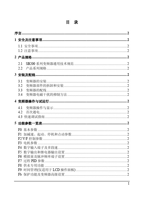
FC 键盘操作及显示设置................................................................................... 2 FF 通讯参数 ....................................................................................................... 2 Fn 厂家参数 ....................................................................................................... 2 FP 故障记录 ....................................................................................................... 2 FU 数据监视....................................................................................................... 2
3 安装及配线.......................................................................................................... 2
3.1 变频器的安装............................................................................................. 2 3.2 变频器部件的拆卸和安装......................................................................... 2 3.3 变频器的配线............................................................................................. 2 3.4 变频器电磁干扰的抑制方法..................................................................... 2
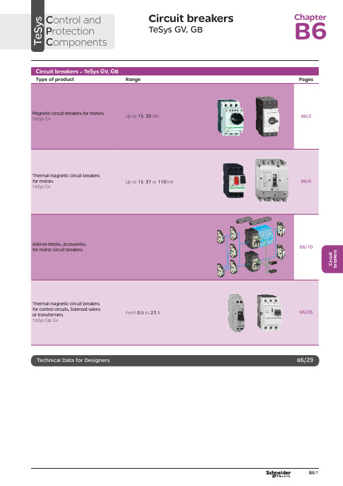
电磁保护设备TeSys GV系列产品参数表说明书
C i r c u i t b r e a k e r sCircuit breakersTeSys GV, GBC ontrol and P rotection C omponentsChapterB60.75g g 1.1g g 1.5375 2.533.5 LR2 K0308GV2LE071.1g g –––––– 2.533.5 LR2 K0308GV2LE071.5g g 1.5g g 3375451 LR2 K0310GV2LE08––– 2.2g g –––451 LR2 K0312GV2LE082.2g g 3501004375 6.378 LR2 K0312GV2LE103g g 410100 5.537510138 LR2 K0314GV2LE144g g 5.510100–––10138 LR2 K0316GV2LE14––––––7.537510138 LRD 14GV2LE14––––––937514170 LRD 16GV2LE165.515507.56751137514170 LR2 K0321GV2LE167.5155096751537518223 LRD 21GV2LE20915401147518.537525327 LRD 22GV2LE2211154015475–––25327 LRD 22GV2LE2215105018.54752237532416LRD 32GV2LE32(1) As % of Icu.g ) > 100 kA.GV2 LE10D F 526144.t i fC i r c u i t b r e a k e r s0.09––––––0.45LRD 03GV2L030.12g g –––0.37g g 0.638LRD 04GV2L040.18g g ––––––0.638LRD 04GV2L04––––––0.55g g 113LRD 05GV2L050.25g g ––––––113LRD 05GV2L05––––––0.75g g 113LRD 06GV2L050.37g g 0.37g g –––113LRD 05GV2L050.55g g 0.55g g 1.1g g 1.622.5LRD 06GV2L06–––0.75g g ––– 1.622.5LRD 06GV2L060.75g g 1.1g g 1.54100 2.533.5LRD 07GV2L07Example: GV3 L32 becomes GV3 L326.(1) As % of Icu. Associated current limiter or fuses, where required. See characteristics page B6/33.g > 100 kA.GV2 L10D F 526145.t i fGV3 L65D F 526146.t i fTeSys GVThermal-magnetic motor circuit breakers GV2 ME0.06gg––––––0.16…0.252.4GV2ME020.09g g––––––0.25…0.405GV2ME030.12 0.18g g g g – –– –– – 0.37 –g–g –0.40…0.638GV2ME040.25gg––– 0.55gg0.63…113GV2ME050.37 0.55 –g g –g g –0.37 0.55 0.75g g g g g g – 0.75 1.1– g g – g g 1…1622.5GV2ME060.75g g1.1gg1.5375 1.6...2.533.5GV2ME071.1 1.5g g g g 1.5 2.2g g g g 2.2 3 3 375 75 2.5 (4)51GV2ME082.2gg350100 43754...6.378GV2ME103 4g g g g 4 5.510 10100 100 5.5 7.5 3 375 756 (10)138GV2ME145.5 –15 –50 –7.5 – 6 –75 – 9 11 3 375 759…14170GV2ME167.5155096751537513…18223GV2ME209154011475 18.537517…23327GV2ME2111154015475 –––20…25327GV2ME22 (3)15105018.54752237524 (32)416GV2ME32Motor circuit breakers from 0.06 to 15 kW / 400 V, with lugsTo order thermal magnetic circuit breakers with connection by lugs, add the digit 6 to the end of reference selected above.Example: GV2 ME08 becomes GV2 ME086.Thermal magnetic circuit breakers GV2 ME with built-in auxiliary contact block With instantaneous auxiliary contact block (composition, see page B6/11):b GV AE1, add suffix AE1TQ to the motor circuit breaker reference selected above. Example: GV2 ME01AE1TQ .b GV AE11, add suffix AE11TQ to the motor circuit breaker reference selected above. Example: GV2 ME01AE11TQ .b GV AN11, add suffix AN11TQ to the motor circuit breaker reference selected above. Example: GV2 ME01AN11TQ .These circuit breakers with built-in contact block are sold in lots of 20 units in a single pack.(1) As % of Icu.(2) The thermal trip setting must be within the range marked on the graduated knob.(3) Maximum rating which can be mounted in enclosures GV2 MC or MP , please consult your Regional Sales Office. g > 100 kA.GV2 ME10D F 526134.t i fC i r c u i t b r e a k e r sTeSys GVTeSys protection componentsThermal-magnetic motor circuit breakers GV2 MEReferences0.06g g ––– 0.16…0.25 2.4GV2ME0230.09g g ––– 0.25…0.405GV2ME0330.120.18g g g g –––0.40…0.638GV2ME0430.250.37g g g g 0.37g g 0.63…113GV2ME0530.370.55g g g g 0.370.550.75g g g g g g 1…1.622.5GV2ME0630.75g g1.1g g 1.6…2.533.5GV2ME0731.11.5g g g g 1.52.2g g g g 2.5…451GV2ME0832.2g g 350100 4…6.378GV2ME10334g g g g 45.510101001006…10138GV2ME1435.515507.5675 9…14170GV2ME1637.515509675 13…18223GV2ME203911151540401147517…23327GV2ME2131115401547520 (25)327GV2ME223Contact blocksDescription Mounting Maximum number Type of contacts Sold in lots of Unitreference Instantaneous auxiliary contactsFront 1N/O + N/C 10GVAE113N/O + N/O 10GVAE203LH side2N/O + N/C 1GVAN113N/O + N/O1GVAN203AccessoryDescriptionApplicationSold in lots of Unitreference Cable end reducerFor connection of conductors from 1 to 1.5 mm 220LA9D99(1) For connection of conductors from 1 to 1.5 mm 2, the use of an LA9 D99 cable end reducer is recommended.(2) Maximum rating which can be mounted in enclosures GV2 MC or MP , please consult your Regional Sales Office (3) The thermal trip setting must be within the range marked on the graduated knob.g > 100 kA.GV2 ME pp 3D F 526135.t i fLA9 D99D F 533898.e p sTeSys GVReferencesTeSys protection componentsThermal-magnetic motor circuit breakersGV2 P, GV3 P and GV3 ME80GV2 P10D F 526137.t i fGV3 P65D F 526139.t i fGV3 P651D F 526140.t i fC i r c u i t b r e a k e r sTeSys GVReferences93610011181001581007.59707010010091150501001001115101010010012…20GV7RS20 2.0109113636100100111518181001001518.58810010015…25GV7RE25 2.0109117070100100111550501001001518.5101010010015…25GV7RS25 2.01018.53610018.522181810010022810025…40GV7RE40 2.01018.57010018.550100221010025…40GV7RS40 2.0102236100301810030810030…50GV7RE50 2.01522701003050100301010030 (50)GV7RS502.01537361004555181810010055810048...80GV7RE80 2.040377010045555050100100551010048...80GV7RS80 2.0404536100–1810075810060...100GV7RE100 2.0404570100–50100751010060...100GV7RS100 2.0405575353510010075903030100100901108810010090 (150)GV7RE1502.020557570701001007590505010010090110101010010090…150GV7RS150 2.02090110353510010011013216030303010010010016020088100100132…220GV7RE220 2.3509011070701001001101321605050501001001001602001010100100132…220GV7RS220 2.350(1) As % of lcu.TeSys protection componentsThermal-magnetic motor circuit breakers GV7 RGV7 RE40D F 526138.t i fGV7 RS220D F 526141.t i f0.12–0.120.180.18–0.370.40…0.6313GV2RT040.090.120.250.370.250.370.370.550.63…122GV2RT050.180.250.370.550.370.550.370.550.750.751.11…1.633GV2RT060.370.750.751.1 1.11.51.6…2.551GV2RT070.550.75 1.11.5 1.51.52.2 2.23 2.5…478GV2RT081.12.22.23344…6.3138GV2RT101.52.234445.5 5.57.56…10200GV2RT142.23 5.55.57.57.59119…14280GV2RT1647.57.5991513…18400GV2RT205.5911111118.517…23400GV2RT21(1) The thermal trip setting must be within the range marked on the graduated knob.GV2 RTD F 526142.t i fC i r c u i t b r e a k e r sblack handle, blue legend plate(1) The thermal trip setting must be within the range marked on the graduated knob.(2) Other accessories such as mounting, cabling and marking accessories are identical to those used for GV2 ME motor circuit breakers, see page B6/13.GV2 RTD F 526142.t i fD F 526340.e p sC i r c u i t b r e a k e r sTeSys GVDescription Mounting Maximum number Type of contacts Sold inlots of Unitreference Instantaneous auxiliary contactsFront (1)1N/O or N/C (2)10GVAE1N/O + N/C 10GVAE11N/O + N/O10GVAE20Side (LH)2N/O + N/C1GVAN11N/O + N/O1GVAN20Fault signalling contact + instantaneous auxiliary contact Side (3) (LH)1N/O (fault)+ N/O1GVAD1010+ N/C1GVAD1001N/C (fault)+ N/O1GVAD0110+ N/C1GVAD0101Short-circuit signalling contactSide (LH)1C/O common point1GVAM11(1 block on RH sideof circuit breaker GV2 ME)50 Hz GVAX11560 Hz GVAX116127 V60 Hz GVAX115220…240 V 50 Hz GVAX22560 Hz GVAX226380…400 V50 Hz GVAX38560 Hz GVAX386415…440 V 50 Hz GVAX415440 V60 Hz GVAX385Add-on contact blocksDescriptionMountingMaximum number Reference Visible isolation block (5)Front (1)1GV2AK00 (6)LimitersAt top(GV2 ME and GV2 P)1GV1L3Independent1LA9LB920(1) Mounting of a GV AE contact block or a GV2 AK00 visible isolation block on GV2 P and GV2 L .(2) Choice of N/C or N/O contact operation, depending on which way round the reversible block is mounted.(3) The GV AD is always mounted next to the circuit breaker.(4) To order an undervoltage trip: replace the dot (p ) in the reference with a U , example: GV AU025. To order a shunt trip: replace the dot (p ) in the reference with an S , example: GV AS025.(5) Visible isolation of the 3 poles upstream of circuit breaker GV2 P and GV2 L .Visible isolation block GV2 AK00 cannot be used with motor circuit breakers GV2 P32 and GV2 L32 (Ith max = 25 A).(6) Ie Max = 32 A.ReferencesTeSys protection componentsThermal-magnetic and magnetic motor circuit breakers GV2 with screw clamp connectionsAdd-on blocks and accessoriesCharacteristics:pages B6/89 and B6/94Dimensions, schemes:pages B6/70 to B6/82LA9LB920D B 126629.e p sC i r c u i t b r e a k e r sTeSys GVTerminal blockfor supply to one or more GV2 G busbar setsConnection from the top1GV1G09Can be fitted with current limiter GV1 L3 (GV2 ME and GV2 P)1GV2G05Cover for terminal block For mounting in modular panels10LA9E07Flexible 3-pole connection for connecting a GV2 to a contactor LC1-D09…D25 Centre distance between mounting rails: 100…120 mm10GV1G02Set of connections upstream/downstream For connecting GV2 ME to a printed circuit board 10GV2GA01“Large Spacing” adapter UL 508 type EFor GV2 P pp H7 (except 32 A)1GV2GH7Clip-in marker holders (supplied with each circuit breaker)For GV2 P , GV2 L, GV2 LE and GV2 RT (8 x 22 mm)100LA9D92ReferencesTeSys protection componentsThermal-magnetic and magnetic motor circuit breakers GV2 with screw clamp connectionsAccessoriesDimensions, schemes:pages B6/70 to B6/82D B 417942.e p sTeSys GVD B 126631.e p sD B 126630.e p sD B 126632.e p s7P B 106297_45.e p sExtended Rotary HandleAllows a circuit breaker or a starter-controller installed in back of an enclosure to be operated from the front of the enclosure.A rotary handle can be black or red/yellow, IP54 or IP65. It includes a function for locking the circuit breaker or the starter in the O (Off) or I (On) position(depending of the type of rotary handle) by means of up to 3 padlocks with a shank diameter of 4 to 8 mm. The extended shaft must be adjusted to use in different size enclosures. The IP54 rotary handle is fixed with a nut (Ø22) to make easierthe assembling. The new Laser Square tool brings the accuracy to align the circuit breaker and the rotary handle.device(padlocks not included)ReferencesTeSys protection componentsThermal-magnetic and magnetic motor circuit breakers GV2 with screw clamp connectionsC i r c u i t b r e a k e r sTeSys GVDescriptionMounting Maximum number Type of contacts Sold inlots of Unitreference Instantaneous auxiliary contactsFront1N/O or N/C (1)10GVAE1N/O + N/C 10GVAE11 (2)N/O + N/O10GVAE20 (2)Side (LH)2N/O + N/C1GVAN11 (2)N/O + N/O1GVAN20 (2)Fault signalling contact + instantaneous auxiliary contactFront 1N/O (fault)+ N/O1GVAED101 (2)N/O (fault)+ N/C1GVAED011 (2)Side (3) (LH)1N/O (fault)+ N/O1GVAD1010+ N/C1GVAD1001N/C (fault)+ N/O1GVAD0110+ N/C1GVAD0101Short-circuit signalling contact Side (LH)1C/O common point 1GVAM11(4)MountingVoltage ReferenceSide(1 block on RH side of circuit breaker)24 V 50 Hz GVA p 02560 Hz GVA p 02648 V 50 Hz GVA p 05560 Hz GVA p 05610050 Hz GVA p 107100…110 V 60 Hz GVA p 107110…115 V 50 Hz GVA p 11560 Hz GVA p 116120…127 V 50 Hz GVA p 125127 V 60 Hz GVA p 115200 V50 Hz GVA p 207200…220 V 60 Hz GVA p 207220…240 V 50 Hz GVA p 22560 Hz GVA p 226380…400 V 50 Hz GVA p 38560 Hz GVA p 386415…440 V 50 Hz GVA p 415415 V 60 Hz GVA p 416440 V 60 Hz GVA p 385480 V 60 Hz GVA p 415500 V 50 Hz GVA p 505600 V60 HzGVA p 505AccessoriesDescription Reference Sets of 3-pole 115 A busbars Pitch: 64 mm2 tap-off GV3 P pp and GV3 L pp GV3G2643 tap-off GV3 P pp and GV3 L pp GV3G364Cover “Large Spacing” UL 508 type E (Only one cover required on supply side)GV3 P ppGV3G66(1) Choice of N/C or N/O contact operation, depending on which way round the reversible block is mounted.(2) Contact blocks available in version with spring terminal connections. Add a figure 3 at the end of the references selected above. Example: GV AED101 becomes GV AED1013.(3) The GV AD pp is always mounted next to the circuit breaker.(4) To order an undervoltage trip: replace the dot (p ) in the reference with a U , example: GV AU025. To order a shunt trip: replace the dot (p ) in the reference with an S , example: GV AS025.Add-on blocks and accessoriesGV3 G66D F 537424.e p sTeSys GVD B 126637.e p sD B 126636.e p sD B 126632.e p s7P B 106297_45.e p sExtended Rotary HandleAllows a circuit breaker or a starter-controller installed in back of an enclosure to be operated from the front of the enclosure.A rotary handle can be black or red/yellow, IP54 or IP65. It includes a function for locking the circuit breaker or the starter in the O (Off) or I (On) position(depending of the type of rotary handle) by means of up to 3 padlocks with a shank diameter of 4 to 8 mm. The extended shaft must be adjusted to use in different size enclosures. The IP54 rotary handle is fixed with a nut (Ø22) to make easierthe assembling. The new Laser Square tool brings the accurency to align the circuit breaker and the rotary handle.For English 10-GVAPSEN For German 10-GVAPSDE For Spanish10-GVAPSES For Chinese 10-GVAPSCN For Portuguese 10-GVAPSPT For Russian 10-GVAPSRU For Italian10-GVAPSITD F 526342.e p sB6/21C i r c u i t b r e a k e r sTeSys GVfor locking the Start button (on open-mounted product)using up to 3 padlocks(padlocks to be ordered separately)External operator for mounting on enclosure door.Red Ø40 knob on yellow plate, padlockable in position O (with up to 3 padlocks). Door locked when knob in position I, and when knob padlocked in position O.GK3AP03(1) 1 voltage trip OR 1 fault signalling contact to be fitted inside the motor circuit breaker.Other versions24 to 690 V, 50 or 60 Hz voltage trips for circuit breakers GV3 ME80.Please consult your Regional Sales Office.ReferencesTeSys protection componentsMotor circuit breakers GV3 ME80 and GK3 EF80Add-on blocks and accessoriesCharacteristics:pages B6/89 and B6/92Dimensions:page B6/47B6/22D F 526344.e p sB6/23C i r c u i t b r e a k e r sTeSys GVThese allow remote indication of the circuit breaker contact states. They can be used for signalling, electrical locking, relaying, etc. They are available in two versions: standard and low level. They include a terminal block and the auxiliary circuits leave the circuit breaker through a hole provided for this purpose.They perform the following functions, depending on where they are located in the circuit breaker:Low levelGV7AB11Fault discrimination devicesThese make it possible to:b either differentiate a thermal fault from a magnetic fault,b or open the contactor only in the event of a thermal fault.VoltageReference a 24...48 and c 24…72 V GV7AD111 (1)z 110…240 VGV7AD112 (1)Electric tripsThese allow the circuit breaker to be tripped via an electrical control signal.b Undervoltage trip GV7 AUv Trips the circuit breaker when the control voltage drops below the tripping threshold, which is between 0.35 and 0.7 times the rated voltage.v Circuit breaker closing is only possible if the voltage exceeds 0.85 times the rated voltage. Circuit breaker tripping by a GV7 AU trip meets the requirements of IEC 60947-2.b Shunt trip GV7 ASTrips the circuit breaker when the control voltage rises above 0.7 times the rated voltage.b Operation (GV7 AU or GV7 AS)v When the circuit breaker has been tripped by a GV7 AU or AS, it must be reset either locally or by remote control. (For remote control, please consult your Regional Sales Office).v Tripping has priority over manual closing: if a tripping instruction is present, manual action does not result in closing, even temporarily, of the contacts.v Durability: 50 % of the mechanical durability of the circuit breaker.TypeVoltageReference Undervoltage trip48 V, 50/60 HzGV7AU055 (1)110…130 V, 50/60 Hz GV7AU107 (1)200…240 V, 50/60 Hz GV7AU207 (1)380…440 V, 50/60 Hz GV7AU387 (1)525 V, 50 HzGV7AU525 (1)Shunt trip48 V, 50/60 HzGV7AS055 (1)110…130 V, 50/60 Hz GV7AS107 (1)200…240 V, 50/60 Hz GV7AS207 (1)380…440 V, 50/60 Hz GV7AS387 (1)525 V, 50 HzGV7AS525 (1)(1) For mounting of a GV7 AD or a GV7 AU or AS.ReferencesTeSys protection componentsThermal-magnetic motor circuit breakers GV7 R with screw clamp connectionsAdd-on blocks and accessoriesCharacteristics:pages B6/51, B6/52 and B6/56Dimensions:pages B6/79 to B6/81Schemes:page B6/83B6/24B6/25C i r c u i t b r e a k e r sTeSys GVDescription ApplicationFor use on contactors Sold in lots of Unitreference Clip-on connectors for GV7 RUp to 150 A, 1.5…95 mm 2–3GV7AC021Up to 220 A, 1.5…185 mm 2–3GV7AC022Spreader 3-pole (1)To increase the pitch to 45 mm–1GV7AC03Terminal shields IP 405 (1)Supplied with sealing accessory–1GV7AC01Phase barriersSafety accessories used when fitting of shields is impossible –2GV7AC04Insulating screens Ensure insulation between the connections and the backplate –2GV7AC05Kits for combination with contactor (2)Allowing link between thecircuit breaker and the contactor. The cover provides protection against direct finger contactLC1 F115…F1851GV7AC06LC1 F225 and F2651GV7AC07LC1 D115 and D1501GV7AC08Replaces the circuit breaker front cover; secured by screws. It includes a device for locking the circuit breaker in the O (Off) position by means of up to 3 padlocks with a shank diameter of 5 to 8 mm (padlocks not included). A conversion accessory allows the direct rotary handle to be mounted on the enclosure door. In this case, the door cannot be opened if the circuit breaker is in the “ON” position. Circuit breaker closing is inhibited if the enclosure door is open.Description TypeDegree of protection Reference Direct rotary handleBlack handle, black legend plate IP 40GV7AP03Red handle, yellow legend plateIP 40GV7AP04Adapter plate (3)Four mounting direct rotary handle on enclosure doorIP 43GV7AP05Allows a circuit breaker installed in the back of an enclosure to be operated from the front of the enclosure. It comprises:b a unit which screws onto the front cover of the circuit breaker,b an assembly (handle and front plate) to be fitted on the enclosure door,b an extension shaft which must be adjusted (distance between the mounting surface and the door: 185 mm minimum, 600 mm maximum). It includes a device for locking the circuit breaker in the O (Off) position by means of up to 3 padlocks with a shank diameter of 5 to 8 mm (padlocks not included). This prevents the enclosure door from being opened.DescriptionTypeDegree of protection Reference Extended rotary handleBlack handle, black legend plate IP 55GV7AP01Red handle, yellow legend plateIP 55GV7AP02Allows circuit breakers not fitted with a rotary handle to be locked in the O (Off) position by means of up to 3 padlocks with a shank diameter of 5 to 8 mm (padlocks not included).Description ApplicationReference Locking deviceFor circuit breaker not fitted with a rotary handleGV7V01(1) Terminal shields cannot be used together with spreaders.(2) The kit comprises links, a protective shield and a depth adjustable metal bracket for the breaker.(3) This conversion accessory makes it impossible to open the door if the device is closed and prevents the device from being closed if the door is open.ReferencesTeSys protection componentsThermal-magnetic motor circuit breakers GV7 R with screw clamp connectionsAccessoriesGV7 AC07D F 537429.e p sGV7 AC08D F 537428.e p sDimensions:pages B6/79 to B6/81B6/260.5 6.63GB2DB051143GB2DB062263GB2DB073403GB2DB084503GB2DB095663GB2DB106833GB2DB1281083GB2DB14101383GB2DB16121653GB2DB20162203GB2DB21202703GB2DB22(1) Conforming to IEC 60947-1.GB2 CBppD F 526243.t i fGB2 CD ppD F 526244.t i fGB2 DBppD F 526245.t i fPresentation, selection :page B6/84Characteristics :pages B6/85 to B6/87Dimensions :page B6/88Schemes :page B6/88B6/27C i r c u i t b r e a k e r s(1) Conforming to IEC 60947-1.Accessories for circuit breakers GB2-CB, DB and CSDescriptionSold in lots of Unitreference Busbar set for supply to 10 GB2 DB or20 GB2 CB or GB2 CS with 2 connectors1GB2G210Supply connector 10GB2G01GB2 CS ppD F 526246.t i fPresentation, selection :page B6/84Characteristics :pages B6/85 to B6/87Dimensions :page B6/88Schemes :page B6/88B6/28B6/29B6/30TeSys GVCharacteristicsTeSys protection componentsMagnetic motor circuit breakers GV2 LE and GV2 LReferences:pages B6/2 and B6/3Dimensions:pages B6/43 to B6/47Schemes:page B6/48add-on contact blocks. Side by side mounting is possible up to 40 °C.(2) When mounting on a vertical rail, fit a stop to prevent any slippage.(1) As % of Icu.Average operating times at 20 °C related to multiples of the setting currentD F 534092.e p s1 3 poles from cold state2 2 poles from cold state3 3 poles from hot stateDynamic stressI peak = f (prospective Isc) at 1.05 Ue = 435 VD F 534093.e p s1 Maximum peak current2 32 A3 25 A4 18 A5 14 A6 10 A7 6.3 A8 4 A9 2.5 A 10 1.6 A11 Limit of rated ultimate breaking capacity on short-circuit of GV2 LE (14, 18, 23 and 25 A ratings).Dynamic stressI peak = f (prospective Isc) at 1.05 Ue = 435 VD F 534094.e p s1 Maximum peak current2 32 A3 25 A4 18 A5 14 A6 10 A7 6.3 A8 4 A9 2.5 A 10 1.6 A11 Limit of rated ultimate breaking capacity on short-circuit of GV2 LE (14, 18, 23 and 25 A ratings).Thermal limit in kA 2s in the magnetic operating zone Sum of I 2dt = f (prospective Isc) at 1.05 Ue = 435 V22Prospective Isc (kA)D F 534095.e p s1 32 A 2 25 A3 18 A4 14 A5 10 A6 6.3 A7 4 A8 2.5 A9 1.6 AThermal limit in kA 2s in the magnetic operating zone Sum of I 2dt = f (prospective Isc) at 1.05 Ue = 435 V22D F 534096.e p s1 25 A and 32 A 2 18 A3 14 A 4 10 A5 6.3 A6 4 A7 2.5 A8 1.6 AThermal limit in kA 2s in the magnetic operating zone Sum of I 2dt = f (prospective Isc) at 1.05 Ue = 435 V22D F 534097.e p s1 32 A (GV2 LE32)2 25 A and 32 A (GV2 L32)3 18 A4 14 A5 10 A6 6.3 A7 4 A8 2.5 A9 1.6 A10 Limit of rated ultimate breaking capacity on short-circuit of GV2 LE (14, 18, 23 and 25 A ratings).Average operating time at 20 °C without prior current flowx the setting current (Ir)D F 534098.e p s1 3 poles from cold state2 2 poles from cold state3 3 poles from hot stateA Thermal overload relay protection zoneB GV3 L protection zoneDynamic stressI peak = f (prospective Isc) at 1.05 Ue = 435 VProspective Isc (kA)D B 418280.e p s1 Maximum peak current2 GV3 L653 GV3 L504 GV3 L405 GV3 L326 GV3 L25Thermal limit in A 2sSum of I 2dt = f (prospective Isc) at 1.05 Ue = 435 V2Prospective Isc (kA)D B 418279.e p s1 GV3 L652 GV3 L503 GV3 L404 GV3 L325 GV3 L25TeSys GVDimensions, mountingD F 537440.e p sD F 537441.e p sD F 537444.e p sTeSys protection componentsMagnetic motor circuit breakers GV2 L and GV2 LETeSys GVDimensions, mounting TeSys protection componentsMagnetic motor circuit breakers GV2 L and GV2 LED B 127415.e p sD B 127414.e p sa b Mini Maxi Mini Maxi GV2 APN pp140250GV2 APN pp + GV APH02151250GV2 APN pp + GV APK11250434--GV2 APN pp + GV APH02 + GV APK11--250445TeSys GVDimensions,mounting Sets of busbars GV2 G445, GV2 G454, GV2 G472, with terminal block GV2 G05D F 537451.e p sGV2 G445224269314359GV2 G454260314368422GV2 G472332404476548D F 537452.e p sD F 537454.e p sGV2 G345 (3 x 45 mm)134GV2 G354 (3 x 54 mm)152TeSys protection componentsMagnetic motor circuit breakers GV2 L and GV2 LED F 537480.e psD F 537435.e p sD F 510637.e p sD F 510638.e p sD B 127416.e p sD B 127417.e p sa b Mini Maxi Mini Maxi GV3 APN pp189300--GV3 APN pp + GV APK12300481GV3 APN pp + GV APH03--200300GV3 APN pp + GV APH03 + GV APK12--300492TeSys GVSchemesTeSys protection componentsMagnetic motor circuit breakers GV2 L, GV2 LE, GV3 LD F 537474.e p sD F 537475.e p sD F 537476.e p sGV2 ME, GV2 P , GV3 ME, GV3 P and GV7 R motor circuit breakers are 3-pole thermal-magnetic circuit breakers specifically designed for the control and protection of motors , conforming to standards IEC 60947-2 and IEC 60947-4-1.Connection GV2GV2 ME and GV2 P circuit breakers are designed for connection by screw clamp terminals.Circuit breaker GV2 ME can be supplied with lugs or spring terminal connections.Spring terminal connections ensure secure, permanent and durable clamping that is resistant to harsh environments, vibration and impact and are even more effective when conductors without cable ends are used. Each connection can take two independent conductors.GV3GV3 circuit breakers feature connection by BTR screws (hexagon socket head), tightened using a n° 4 Allen key.This type of connection uses the Ever Link ® system with creep compensation (1) (Schneider Electric patent).This technique makes it possible to achieve accurate and durable tightening torque, in order to avoid cable creep.GV3 circuit breakers are also available with connection by lugs. This type of connection meets the requirements of certain Asian markets and is suitable for applications subject to strong vibration, such as railway transport.GV7GV7 circuit breakers: with connection by screw clamp terminals (for bars and lugs) and by clip-on connectors.OperationControl is manual and local when the motor circuit breaker is used on its own.Control is automatic and remote when it is associated with a contactor.GV2 ME and GV3 ME80Pushbutton control.Energisation is controlled manually by operating the Start button “I” 1.De-energisation is controlled manually by operating the Stop button “O” 2, or automatically by the thermal-magnetic protection elements or by a voltage trip attachment.GV2 P , GV3 P and GV7 Rb Control by rotary knob: for GV2 P and GV3 P b Control by rocker lever: for GV7 R.Energisation is controlled manually by moving the knob or rocker lever to position “I” 1.De-energisation is controlled manually by moving the knob or rocker lever to position “O” 2.De-energisation due to a fault automatically places the knob or rocker lever in the “Trip” position 3.Re-energisation is possible only after having returned the knob or rocker lever to position “O”.(1) Creep: normal crushing phenomenon of copper conductors, that is accentuated over time.GV2 MEwith screw clamp terminals124D F 526134.t i fGV2 MEwith spring terminals connections124D F 526135.t i fGV3 P1324D F 526136.t ifGV2 P1342D F 526137.t i fGV7 R132D F 526138.t i f。
ML725B16F中文资料

ML7xx16SERIESTYPE NAMEMITSUBISHI LASER DIODES2.5Gbps InGaAsP DFB LASER DIODEDESCRIPTIONML7xx16 series are uncooled DFB (Distributed Feedback) laser diodes for 2.5Gbps transmission emitting light beam at 1310nm./4shifted grating structure is employed to obtain excellent SMSR performance under 2.5Gbps modulation. Furthermore, ML7xx16 can operate in the wide temperature range form -20ºC to 85ºC without any temperature control.FEATURES2.5Gbps transmission APPLICATIONABSOLUTE MAXIMUM RATINGS/4 phase shifted grating structure High side-mode-suppression-ratio (typical 45dB)Wide temperature range operation (-20ºC to 85ºC )High resonance frequency (typical 11GHz)ELECTRICAL/OPTICAL CHARACTERISTICS Tc=25ºCThreshold current Operation current Operating voltage Peak wavelength Beam divergence angle (parallel)(perpendicular)Side mode suppression ratioMonitoring current (PD)Rise and fall time(10%-90%)Symbol ParameterConditionsMin.Typ.Max.Unit Ith CW -1015mA Iop CW,Po=5mW -3040mA V VopCW,Po=5mW 1.1 1.8pCW,Po=5mW,Tc=-20ºC +85ºC 1310nm CW,Po=5mW-2547deg.CW,Po=5mW,VRD=1V -11-20-SMSR fr 2.48832Gbps, Ibias=Ith,Ipp=40mA 40-30deg.3545pFResonance frequency tr,tf 2.0mA dB 150GHz 12901330-LimitsmA CW,Tc=85ºC CW,Po=5mW,Tc=85ºC CW,Po=5mW2.48832Gbps, Ibias=Ith,Ipp=40mA not including package Im Id CtCapacitance (PD)VRD=5V VRD=5V,f=1MHz-3550-75100mA mW/mA 0.250.18-CW,Po=5mW100-psec 0.1- 1.0A CW,Po=5mW,Tc=-20ºC +85ºC--10-Slope efficiencyDark current (PD)Symbol ParameterConditionsRatings Unit IF Laser forward current 200mA VRL Laser reverse voltage -2V Tc Operation temperature --20~+85TstgStorage temperature--40~+100ºCºC VRD -20V Po Output power CW 6mW PD reverse voltage IRD PD forward current -2mA -1.0Min.2.0Min.3.55±0.1-0.030.25±0.03G l a s s4-0.45±0.052.0±0.25(P.C.D.)4.25mmML7xx16SERIESMITSUBISHI LASER DIODES2.5Gbps InGaAsP DFB LASER DIODE。
W7527-16D 操作手册
单绳公称牵引力
钢丝绳
卷筒
电机
减速机
制动器
2-6
规格
44860
35×7-18-1870
最大线速度
m/min
180
最大卷筒转速
r/min
69
容绳量
m
700 米(6 层)
型号
起升机构
H55FL40-700
N
YZPFM280S2-6
功率
kW
55
转速
r/min
985
型号
MB3H070H35.5A
195
模数 m
14
齿数 z
12
变位系数 x
+0.5
减速机
S75CA-130LB14/12A
S75CA-130LB14/12A(M)
输出端
齿轮参数
主机回转速度
r/min
0~0.7
功率
kW
11
转速
r/min
1465
流量
l/min
17.5
工作压力
MPa
31.5
缸/杆直径
mm
200/140
最大顶升力
t
98.9
1 总图布置示意图
1.1塔机整体外形尺寸
图 2.1-1 支腿固定式整机外型尺寸
75
起重臂
侧
L1(m)
77.2
72.5
74.7
70
72.2
67.5
69.7
65
67.2
62.5
64.7
60
62.2
57.5
59.7
55
57.2
52.5
英格索兰猛虎空压机型号参数详解
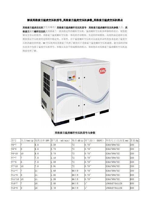
解说英格索兰猛虎空压机型号_英格索兰猛虎空压机参数_英格索兰猛虎空压机特点英格索兰猛虎空压机型号有哪些?英格索兰猛虎螺杆空压机型号,英格索兰猛虎螺杆空压机参数大全。
英格索兰猛虎螺杆空压机是英格索兰一款高稳定性的螺杆空压机,猛虎螺杆空压机各种独特的设计,使您能够安全省心的使用。
英格索兰猛虎螺杆空压机一体化的冷却模块、先进的控制模块、高效的油过滤和分离模块保证空压机使用过程的中稳定性、可靠性。
对于猛虎螺杆空压机可以说是革命性的技术造就了猛虎空压机的最佳的性能。
99空压机网从英格索兰代理了解到关于英格索兰猛虎螺杆空压机最新、最全面的详细信息其中包括了猛虎空压机型号、参数以及各个组成模块的特点,帮助您在对英格索兰猛虎螺杆空压机选购前有所了解。
英格索兰猛虎螺杆空压机型号与参数空压机型号()英格索兰猛虎螺杆空压机主机各模块详细介绍英格索兰猛虎螺杆空压机主机驱动模块:英格索兰猛虎空压机进气端采用滚柱轴承,受力均匀,稳定性高;排气端采用一对背靠背滚锥轴承,同时抵消径向力和轴向力;猛虎空压机这一设计独特的储油槽,大大降低了干摩擦时间,延长了英格索兰猛虎空压机使用寿命。
英格索兰猛虎螺杆空压机冷却模块:英格索兰猛虎空压机采用体式冷却模块,专利设计的冷却风扇配合特别设计的导风罩提高了猛虎空压机机组的运行效率。
英格索兰猛虎螺杆空压机控制模块:英格索兰猛虎空压机特有的冷室和热室结构设计,将独立的控制模块置于冷室中,避免了英格索兰猛虎空压机因高温导致电气元件过早老化,紧凑的设计更加节省猛虎空压机机组空间。
英格索兰猛虎螺杆空压机油过滤和分离模块:英格索兰猛虎空压机集成了管道和传感器,比其同类空压机产品减少15%的连接点,大大降低了泄漏的发生率,格索兰猛虎空压机独特的油分离模块设计,大大降低了空气含油量,能达到3ppm以下的行业领先水平,猛虎空压机所有的管路连接都采用O型圈密封,从根本上提高了英格索兰猛虎空压机防泄漏等级。
英格索兰猛虎螺杆空压机精密的传动系统:●英格索兰猛虎螺杆空压机5.5-37kV机组采用单根Poly-V宽皮带进行传动,相比多根细皮带传动,应力更分散,稳定性更高;●英格索兰猛虎螺杆空压机45-160kW机组采用高精度的齿轮传动。
美国寿力空压机操作手册88290006-608(02)
4.4 常规运行 ............................................................................................................................................. 12
3.2 寿力压缩机主机.................................................................................................................................... 7
3.3 冷却润滑系统 ....................................................................................................................................... 7
第四章 压缩机的操作 ..................................................................................................................................... 12
4.1 安全操作规程 ..................................................................................................................................... 12
第三章 压缩机系统 ........................................................................................................................................... 7
夜光-Lite GR-系列燃油冷却柴机说明书
Parts ManualNIGHT-LITE™ GR-SERIES Air Cooled DieselPart No.: 118304Revision: BenCopyright ©2021 Briggs & StrattonMilwaukee, WI, USA. All rights reserved.TABLE OF CONTENTS1.0 TRAILER BASE PARTSAxle and Wheels .............................................................................................(1.1)Fenders ...........................................................................................................(1.2)Tongue .............................................................................................................(1.3)Outriggers ........................................................................................................(1.4)Enclosure Base Parts .....................................................................................(1.5)Enclosure Trim Parts ......................................................................................(1.6)Lift Bow ...........................................................................................................(1.7)Manual Canister ...............................................................................................(1.8)2.0 TOWER GROUPTower Pedestal ................................................................................................(2.1)Tower Section 1 ...............................................................................................(2.2)Tower Section 2 ...............................................................................................(2.3)Tower Section 3 ...............................................................................................(2.4)Tower Round Section and Light Bar ...............................................................(2.5)3.0 ELECTRICAL AND LIGHTING GROUPControl Box Install Group ...............................................................................(3.1)Control Box Interior and Weather Shields .....................................................(3.2)Control Box Deep Sea Controller and Light Switches ..................................(3.3) Control Box (60Hz) Main Breaker and GFCI Group .....................................(3.4)Control Box (50Hz) Main Breaker and Schuko Group ..................................(3.5)Tower Cord ......................................................................................................(3.6)350W LED Lighting ........................................................................................(3.7)350W LED Light Diffuser ...............................................................................(3.8)250W LED Lighting ........................................................................................(3.9)250W LED Light Diffuser .............................................................................(3.10)Trailer Lighting ...............................................................................................(3.11)Tail Light Hole Covers ....................................................................................(3.12) Night-Lite™ GR-Series Chain Parts CatalogTABLE OF CONTENTS4.0 ENGINE AND GENERATOR GROUPYanmar L70W Air-Cooled Diesel Engine .......................................................(4.1) Yanmar L70N (Int’l) Air-Cooled Diesel Engine ..............................................(4.2) Engine Cooling Fan and E-Stop Button .........................................................(4.3) Engine Air Vents ............................................................................................(4.4) Linz 4.3kW 60Hz Generator ...........................................................................(4.5) Linz 3.5kW 50Hz Generator ...........................................................................(4.6) Fuel Tank and Fuel Lines ...............................................................................(4.7) Battery Group ..................................................................................................(4.8) 5.0 DECALSRight Side Decals ...........................................................................................(5.1) Left Side English and French Decals .............................................................(5.2) Left Side International Wordless Decals ........................................................(5.3) Front Side English and French Decals ...........................................................(5.4) Front Side International Wordless Decals ......................................................(5.5) Rear Side English and French Decals ...........................................................(5.6) Rear Side International Wordless Decals ......................................................(5.7) Top View English and French Decals .............................................................(5.8) Top View International Wordless Decals .........................................................(5.9) Door Interior English and French Decals ......................................................(5.10) Door Interior International Wordless Decals ..................................................(5.11)©2021 Briggs & StrattonSN 25-000001 and UP 1.1 - Axle and WheelsNight-Lite™ GR-Series Chain Parts Catalog1.1SN 25-000001 and UP 1.1 - Axle and Wheels©2021 Briggs & Stratton1.1SN 25-000001 and UP 1.2 - FendersNight-Lite™ GR-Series Chain Parts Catalog1.2SN 25-000001 and UP 1.2 - Fenders©2021 Briggs & Stratton1.2SN 25-000001 and UP 1.3 - TongueNight-Lite™ GR-Series Chain Parts Catalog1.3SN 25-000001 and UP 1.3 - Tongue©2021 Briggs & Stratton1.3SN 25-000001 and UP 1.4 - OutriggersNight-Lite™ GR-Series Chain Parts Catalog1.4SN 25-000001 and UP 1.4 - OutriggersSN 25-000001 and UP 1.5 - Enclosure Base Parts (1 of 2)SN 25-000001 and UP 1.5 - Enclosure Base Parts (1 of 2)SN 25-000001 and UP 1.5 - Enclosure Base Parts (2 of 2)SN 25-000001 and UPSN 25-000001 and UP 1.6 - Enclosure Trim PartsSN 25-000001 and UP 1.7 - Lift BowSN 25-000001 and UP 1.7 - Lift BowSN 25-000001 and UP 1.8 - Manual CanisterSN 25-000001 and UP 1.8 - Manual CanisterSN 25-000001 and UP 2.1 - Tower PedestalSN 25-000001 and UP 2.1 - Tower PedestalSN 25-000001 and UPSN 25-000001 and UP 2.2 - Tower Section 1SN 25-000001 and UP 2.3 - Tower Section 2SN 25-000001 and UP 2.3 - Tower Section 2SN 25-000001 and UP 2.4 - Tower Section 3SN 25-000001 and UP 2.4 - Tower Section 3SN 25-000001 and UP 2.5 - Tower Round Section and Light BarSN 25-000001 and UP 2.5 - Tower Round Section and Light BarSN 25-000001 and UP 3.1 - Control Box Install GroupSN 25-000001 and UP 3.1 - Control Box Install GroupSN 25-000001 and UP 3.2 - Control Box Interior and Weather ShieldsSN 25-000001 and UP 3.2 - Control Box Interior and Weather ShieldsSN 25-000001 and UP3.3 - Control Box Deep Sea Controller and Light Switches74895131066SN 25-000001 and UP 3.3 - Control Box Deep Sea Controller and Light SwitchesSN 25-000001 and UP 3.4 -Control Box (60Hz) Main Breaker and GFCI GroupSN 25-000001 and UP 3.4 -Control Box (60Hz) Main Breaker and GFCI GroupSN 25-000001 and UP 3.5 - Control Box (50Hz) Main Breaker and Schuko GroupSN 25-000001 and UP 3.5 - Control Box (50Hz) Main Breaker and Schuko GroupSN 25-000001 and UP 3.6 - Tower CordSN 25-000001 and UP 3.6 - Tower CordSN 25-000001 and UP 3.7 - 350W LED LightingSN 25-000001 and UP 3.7 - 350W LED LightingSN 25-000001 and UP 3.8 - 350W LED Light DiffuserSN 25-000001 and UP 3.8 - 350W LED Light DiffuserSN 25-000001 and UP 3.9 - 250W LED LightingSN 25-000001 and UP 3.9 - 250W LED LightingSN 25-000001 and UP 3.10 - 250W LED Light Diffuser。
48V165F规格书中文版.doc

PRODUCT SPECIFICATIONS (cont.)产品规格BMOD0083 BMOD0110 BMOD0165 ELECTRICAL 电气的Capacitance 容量83 F 110 F 165 F Nominal capacitance 正常容量-5 % / +20% -5 % / +20% -5 % / +20% Tolerance capacitance 容量偏差Voltage 电压Rated voltage 额定电压48.6 V DC 48.6 V DC 48.6 V DC Resistance 电阻10.3 mΩ8.1 mΩ 6.3 mΩESR, DC (max., roomtemperature) 电阻,直流(最大的,常温)9.8 mΩ 5.6 mΩ 5.2 mΩESR, AC (max., roomtemperature, 1kHz) 电阻,交流(最大的,常温,1KHZ)Current 电流61 A 79 A 98 A Maximum continuouscurrent 最大持续电流1,090 A 1,410 A 1,970 A Maximum peak current, 1sec. 最大峰值电流,1秒3 mA 4.2 mA 5.2 mA Leakage current (After 72hours at 25°C. Initial leakagecurrent can be higher.) 泄露电流(25°C,72小时后,初始的泄露电流会更高)TEMPERATURE 温度-40oC to +65oC -40oC to +65oC -40oC to +65oC Operating temperaturerange (Cell case temperature)可操作温度范围(单体箱内温度)-40oC to +70oC -40oC to +70oC -40oC to +70oC Storage temperature range(Stored uncharged) 存储温度范围(不带电存储)POWER AND ENERGY 功率和能量2,700 W/kg 3,100 W/kg 3,300 W/kg Usable power density, Pd 可用功率密度,PdUsable power 可用功率27,500 W 35,000 W 45,000 W5,570 W/kg 6,450 W/kg 6,940 W/kg Impedance match powerdensity, Pmax 阻抗匹配功率密度,Pmax2.65 Wh/kg3.19 Wh/kg4.01 Wh/kg Gravimetric energy density,Emax 重量能量密度EmaxEnergy available 可用能量27 Wh 36 Wh 54 WhBMOD0083 BMOD0110 BMOD0165DC LIFESPAN 直流寿命2,000 hours 2,000 hours 2,000 hours Endurance (at rated voltageand temperature) 耐久性(在额定电压和温度下)≤20% ≤20% ≤20% Capacitance change (%decrease from rated value) 容量变化(与额定值相比下降的百分率)≤60% ≤60% ≤60% ESR change (% increase fromrated value) 电阻变化(与额定值相比上升的百分率)10 years 10 years 10 years Life Test (at rated voltage and20°C) 寿命测试(20°C),额定电压下测试)≤20% ≤20% ≤20% Capacitance change (%decrease from rated value) 容量变化(与额定值相比下降的百分率)≤100% ≤100% ≤100% ESR change (% increase fromrated value) 电阻变化(与额定值相比上升的百分率)1 million 1 million 1 million Cycle Test (Number of cycles)循环测试(循环次数)≤20% ≤20% ≤20% Capacitance change (%decrease from rated value) 容量变化(与额定值相比下降的百分率)≤100% ≤100% ≤100% ESR change (% increase fromrated value) 电阻变化(与额定值相比上升的百分率)2 years 2 years 2 years Shelf Life(Storage uncharged up tomaximum storage temperature)保质期,不带电存储到最大存储温度下10% 10% 10% Capacitance change (%decrease from rated value) 容量变化(与额定值相比下降的百分率)50% 50% 50%ESR change (% increase fromrated value) 电阻变化(与额定值相比上升的百分率)CONNECTION 连接M8, M10 Screw M8, M10 Screw M8, M10 Screw Power output terminals 功率输出端子Monitoring and control 监控NTC NTC NTCCell management 单体管理VMS 2.0 VMS 2.0 VMS 2.0750 V DC 750 V DC 750 V DC Maximum series voltage 最大系列电压PHYSICAL 物理规格Dimensions 尺寸See drawing See drawing See drawing Weight 重量10.3 kg 11.3 kg 13.5 kg SAFETY 安全性4,700 A 6,000 A 7,700 A Short circuit current (Currentpossible with short circuit fromrated voltage. Do not use as anoperating current.) 短路电流(额定电压下电流可能短路,不要作为操作电流使用)Certifications 证书,认证RoHS RoHS UL810a, RoHS50.4 V DC 50.4 V DC 50.4 V DC Surge voltage 冲击电压(Voltage above this level cancause catastrophic failure.) 高于这个水平的电压会引起灾难性故障Isolation voltage 绝缘电压2,500 V DC 2,500 V DC 2,500 V DC ENVIRONMENTAL RATINGS 环境等级IP65 IP65 IP65 Degrees of protection 保护程度Vibration resistance 抗震性SAE J2380 SAE J2380 SAE J2380 Shock resistance 耐震强度SAE J2464 SAE J2464 SAE J2464。
大金多联机参数表(4页)

大金多联机参数表(4页)Good is good, but better carries it.精益求精,善益求善。
、-^,…、;}:¥~…]|》|&$!¥~~]^}[&(?>2重尺型配面电路电丝熔重纹水气液尺转静风尺(制制电容热容电数平台观区心出害制出要制口出心,出要制位置型内格规配择根气丝选来值得音集四、处机距是面得收一正距是面值记本一影声反周,态安。
内消是运中样℃℃温室:内℃外,:内电线电制制范充名冷重气液尺管运间转转静尺风制制电容制容定电方数台景公观出区中位置匹型-------------------------------------------室外机型号 RUXYQ24ABRUXYQ42ABRUXYQ46AB匹数HP 244246安装位置及位号保卫控制中心要害区出入口HYG-0500-OU-1综合办公楼观景平台HYG-6500-MY-Y08 综合办公楼观景平台HYG-6500-MY-Y09数量 台 1 1 1 组合方式 12+12 20+22 8+16+22 电源三相50Hz 380V*1额定制冷容量 kw 61.5 117.5 128.9 *2额定制热容量 kw 69 132 144 额定耗电量 制冷 kw 20.2 36.7 38 制热kw 18.7 35.2 36.4 风扇风量 m3/min 271 261+271 162+260+271 机器尺寸 mm 1657*1240*7651657*1240*765+ 1657*1240*7651657*930*765+ 1657*1240*765+ 1657*1240*765机外静压 Pa 81 *3运转音正面运转音 dB(A) 63 66 66 四面运转音 dB(A)666969℃℃℃*2 室内温度:20℃DB/室外温度:7℃DB,6℃WB。
*3 本样本中记载的运转音是在消音室内测得。
在实际安装状态中,因受周围噪音及反射声的影响,一般要高于本样本的记载值。
- 1、下载文档前请自行甄别文档内容的完整性,平台不提供额外的编辑、内容补充、找答案等附加服务。
- 2、"仅部分预览"的文档,不可在线预览部分如存在完整性等问题,可反馈申请退款(可完整预览的文档不适用该条件!)。
- 3、如文档侵犯您的权益,请联系客服反馈,我们会尽快为您处理(人工客服工作时间:9:00-18:30)。
(perpendicular) CW,Po=5mW 2.48832Gbps, Ibias=Ith,Ipp=40mA 2.48832Gbps, Ibias=Ith,Ipp=40mA not including package CW,Po=5mW,VRD=1V VRD=5V VRD=5V,f=1MHz
Jan. 2002
PD
LD
±0.1 2.1±0.15 1.2
(4)
(1)
ML720J16S
φ 2.0±0.25 (P.C.D.) (1) (2) 4-φ 0.45±0.05
18 ±1
ML725J16F
Top View
φ 5.6 +0 -0.03 φ 4.3
(Dimension:mm)
(0.25)
(3) 2-90º
(4)
元器件交易网
MITSUBISHI LASER DIODES
ML7xx16 SERIES
2.5Gbps InGaAsP DFB LASER DIODE
TYPE NAME
ML725B16F/ML720J16S/ML725J16F
FEATURES
λ/4 phase shifted grating structure Wide temperature range operation (-20ºC to 85ºC ) High side-mode-suppression-ratio (typical 45dB) High resonance frequency (typical 11GHz)
Fig. 1 Light output v.s. forward current
-20°C 25°C 50°C 85°C
-30 Light output Po (mW)
Po=5mW
-40 -50 -60 -70 -80 -90 1290
-20°C 25°C 50°C 85°C
1300
1310
1320
元器件交易网
MITSUBISHI LASER DIODES
ML7xx16 SERIES
2.5Gbps InGaAsP DFB LASER DIODE OUTLINE DRAWINGS
ML725B16F
φ 5.6 +0 -0.03 φ 4.25 φ 3.55±0.1
(Dimension:mm)
(0.25) (3) 2-90º
(4)
(2) (0.25)
(3)
Case
(1) (4)
1±0.1 0.25±0.03 (Glass) φ 2.0Min. φ 1.0Min. 1.27 ±0.03 Emitting Facet Reference Plane
PD
LD
±0.1 2.1±0.15 1.2
(2) ML725B16F
DESCRIPTION
ML7xx16 series are uncooled DFB (Distributed Feedback) laser diodes for 2.5Gbps transmission emitting light beam at 1310nm. λ/4 shifted grating structure is employed to obtain excellent SMSR performance under 2.5Gbps modulation. Furthermore, ML7xx16 can operate in the wide temperature range form -20ºC to 85ºC without any temperature control.
APPLICATION ABSOLUTE MAXIMUM RATINGS
Symbol Po IF VRL IRD VRD Tc Tstg Parameter Output power Laser forward current Laser reverse voltage PD forward current PD reverse voltage Operation temperature Storage temperature 2.5Gbps transmission Conditions CW Ratings 6 200 2 2 20 -20 ~+85 -40 ~+100 Unit mW mA V mA V ºC ºC
1330
Forward current If (mA)
Fig. 2 Spectrum
1.2 Relative light output 1.0 0.8 0.6 0.4 0.2 0.0 -60
Fig. 3 Far field pattern
Po=5mW Tc=25°C θ°)
元器件交易网
MITSUBISHI LASER DIODES
ML7xx16 SERIES
2.5Gbps InGaAsP DFB LASER DIODE
TYPICAL CHARACTERISTICS
10 Light output Po (mW) 8 6 4 2 0 0 20 40 60 80 100 Forward current If (mA)
ELECTRICAL/OPTICAL CHARACTERISTICS (Tc=25ºC)
Symbol Ith Iop Vop η λp SMSR θ// θ⊥ fr tr,tf Im Id Ct
Parameter Threshold current Operation current Operating voltage Slope efficiency Peak wavelength Side mode suppression ratio Beam divergence angle (parallel) Resonance frequency Rise and fall time(10%-90%) Monitoring current (PD) Dark current (PD) Capacitance (PD) CW CW,Tc=85ºC CW,Po=5mW CW,Po=5mW,Tc=85ºC CW,Po=5mW CW,Po=5mW CW,Po=5mW,Tc=-20ºC~+85ºC CW,Po=5mW,Tc=-20ºC~+85ºC CW,Po=5mW Conditions Limits Min. 0.18 1290 35 0.1 MITSUBISHI ELECTRIC Typ. 10 35 30 75 1.1 0.25 1310 45 25 30 11 100 10 Max. 15 50 40 100 1.8 1330 40 47 150 2.0 0.1 20 Unit mA mA mA mA V mW/mA nm dB deg. deg. GHz psec mA µA pF
20
40
60
(2) (0.25)
(3)
Case
(1) (4)
1±0.1 φ 3.75±0.1
PD
LD
3.97 ±0.15
(7.51)
1.27 ±0.03
Emitting Facet Reference Plane
(2) ML725J16F
(1)
18 ±1
1.2 ±0.1
φ 2.0±0.25 (P.C.D.) 4-φ 0.45±0.05 (1) (2)
(1)
18 ±1
φ 2.0±0.25 (P.C.D.) (1) (2)
4-φ 0.45±0.05
φ 5.6 +0 -0.03
(Dimension:mm)
ML720J16S
2-90º
φ 4.25 φ 3.55±0.1 (0.25) (3)
(2)
(1) (4) (2) (0.25)
(3)
Case
1±0.1 0.25±0.03 (Glass) φ 2.0Min. φ 1.0Min. 1.27 ±0.03 Emitting Facet Reference Plane
