opnet 四天培训教程 Modeler_Day2
opnet教程实例
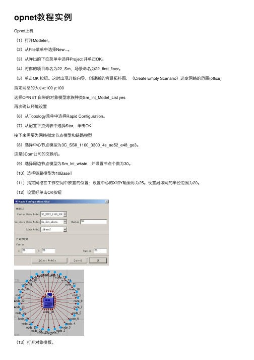
opnet教程实例Opnet上机(1)打开Modeler。
(2)从File菜单中选择New...。
(3)从弹出的下拉菜单中选择Project 并单击OK。
(4)将你的项⽬命名为22_Sm,场景命名为22_first_floor。
(5)单击OK 按钮。
这时出现开始向导,创建新的背景拓扑图,(Create Empty Scenario)选定⽹络的范围(office)指定⽹络的⼤⼩x:100 y:100选择OPNET ⾃带的对象模型家族种类Sm_Int_Model_List yes再次确认环境设置(6)从Topology菜单中选择Rapid Configuration。
(7)从配置下拉列表中选择Star,单击OK.接下来需要为⽹络指定节点模型和链路模型(8)选择中⼼节点模型为3C_SSII_1100_3300_4s_ae52_e48_ge3。
这是3Com公司的交换机。
(9)选择周边节点模型为Sm_Int_wkstn,并设置节点个数为30。
(10)选择链路模型为10BaseT(11)指定⽹络在⼯作空间中放置的位置:设置中⼼的X和Y轴坐标为25。
设置局域⽹的半径范围为20。
(12)设置好单击OK按钮(13)打开对象模板。
(14)找到Sm_Int_server对象,并将它放置在⼯作空间中。
(16)在对象模板中找到10BaseT链路对象。
(17)在服务器上单击⿏标左键,移动光标,再单击星型⽹络的中⼼节点。
(18)单击⿏标右键结束链路创建。
(19)在对象模板中找到Sm_Application_Config对象并将其放置在⼯作空间中。
(20)单击右键,光标重新移到对象模板中,单击Sm_Profile_Config,并将其放置在⼯作空间中,单击⿏标右键。
(21)关闭对象模板。
统计结果:(1)在服务器节点(node_31)上单击⿏标右键,从弹出的菜单中选择Choose Individual Statistics。
(2)单击Node Statistics->Ethernet,选择Load(bits/sec)统计量。
OPNET_用户指南(中文)

文件格式 二进制文件 二进制文件 二进制文件 ASCII 数据 C 代码 目标代码 可执行程序 二进制文件 ASCII 数据 C 代码 C++代码 C 代码 C++代码 C/C++头文件 目标代码 二进制文件 二进制文件 二进制文件 二进制文件 二进制文件 二进制文件 二进制文件 二进制文件 二进制文件 二进制文件 二进制文件 二进制文件 二进制文件 二进制文件/可编辑 二进制文件/可导入仿真 二进制文件 C 代码 C+& of 72
.pr.o .prj .ps.c .ps.cpp .ps.o .sd .seq .sim
版权所有,翻印必究,只用于学习研究
进程模型 项目模型 管道阶段 C 文件 管道阶段 C++文件 管道目标文件 仿真描述 仿真序列 可执行的仿真
目标文件 二进制文件 C 代码 C++代码 目标文件 ASCII 文本 ASCII 数据 可执行文件
OPNET 用户指南翻译
以下文档为笔者根据 OPNET 的联机帮助文档翻译过来的,供大家学习参看,请勿用于商业 用途,有问题可以和本人联系,由于本人主要是使用 Modeler 进行编程,所以只是翻译了这 部分的内容。希望我的工作能起到抛砖引玉的作用,有更多的文档能够出现从而简便大家对 OPNET 的学习。
Page 6 of 72
版权所有,翻印必究,只用于学习研究
链路编辑器 在对话框中规定了如下信息: Link Types(所支持的链路类型)
每一链路模型可以支持四种基本的链路类型中的一种或多种,即ptsimp(点对点双工链 路)、ptdup(点对点单工链路)、bus(总线链路)和bus tap(总线分接链路)。请注意,无线 链路的设计不包含在链路编辑器中,它是由仿真内核(Simulation Kernel)经过动态定义生 成的与结点相对位置、传输及运行环境中诸多因素相关的函数。 Key Words(关键字)
OPNET-Modeler通信仿真平台简介分析
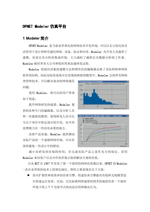
OPNET Modeler仿真平台1 Modeler简介OPNET Modeler 是当前业界领先的网络技术开发环境,可以以无与伦比的灵活性用于设计和研究通信网络、设备、协议和应用。
Modeler 为开发人员提供了建模、仿真以及分析的集成环境,大大减轻了编程以及数据分析的工作量。
Modeler被世界各大公司和组织用来加速研发过程。
Modeler的面向对象的建模方法和图形化的编辑器反映了实际网络和网络组件的结构,因此实际的系统可以直观的映射到模型中。
Modeler支持所有网络类型和技术,可以解决复杂的网络通信问题。
使用Modeler,将可以给用户带来如下利益:提升网络研发的成果:Modeler提供的各种专门的编辑器,以及分析工具和一些最新的模型,使得研发人员可以专注于项目中特定部分的开发,而不用浪费精力在一些没有必要的地方。
改善产品质量:Modeler提供测试实际产品的一个虚拟网络环境,可以有效的避免一些设计中的错误。
减小从研发到市场的时间:在完成实际产品之前作充分的验证,采用Modeler来向客户以及合作伙伴展示您的解决方案的价值。
自从MIT在1987年发布了第一个商用的网络仿真器以来,OPNET的Modeler 一直在业界保持技术上的领先地位,特性主要表现在以下方面: 高可扩展性和高效率的仿真引擎。
快速仿真引擎能对有线和无线模型进行快速运行仿真,比如,以比标准网络速度快得多的速度仿真一个地形环境下的上千个无线节点的动态应用和路由行为。
●层次化的网络模型。
使用无限嵌套的子网来建立复杂的的网络拓扑结构●面向对象的建模方式。
节点和协议以基类和派生类进行建模。
●简单明了的建模方法。
Modeler 建模过程分为三个层次,过程(Process)层次,节点(Node)层次,以及网络(Network)层次。
在过程层次模拟单个对象的行为,在节点层次将其互连成设备,在网络层次将这些设备互连组成网络。
几个不同的网络场景组成“项目”,以比较不同的设计。
OPNET基础入门
OPNET基础入门1.从协议间关系看,节点模块建模完全符合OSI 标准,业务层->TCP 层->IP 层->IP 封装层->ARP 层->MAC层->物理层2.从网络物件层次关系看,提供了三层建模机制,最底层为进程模型,以状态机来描述协议;其次为节点模型,由相应的协议模型构成,反映设备特性;最上层为网络模型。
三层模型和实际的协议、设备、网络完全对应,全面反映了网络的相关特性。
3.在进程层次模拟单个对象(模块)的行为,在节点层次中将其(模块)互连成设备(节点),在网络层次中将这些设备互连组成网络。
4.使用Modeler 仿真可以大体分成6 个步骤:配置网络拓扑(Topology->Rapid Configuration)、配置业务、收集统计量(对象统计量和全局统计量)、运行仿真并查看结果(设置repositories属性Edit->Preferences)、调试模块再次仿真、最后发布结果和拓扑报告。
5.在任何打开OPNET 时候,最高层次永远为一个工程,每个场景代表网络模块,一个工程就是一组仿真环境,一个场景就是其中的一个具体网络仿真环境配置方案(如网络拓扑、协议、流量等)。
6.工程编辑器最开始用来新建一个工程,指定工程名字和第一个场景名字后,网络配置小精灵(StartupWizard)就出来了。
可以选择手动建立网络,或者可以从特殊格式文件导入。
之后设定网络的范围,同时也可以指定度量单位,可以是经纬度、米、公里、英尺、英里等。
接着选择常用的模板家族(Model Family),把它们包含(include)进去后,它们作为构建网络的候选组件。
7.可以设置背景的显示分辨率(Resolution:pixels/degree)和背景网格的解析率(Division)。
View->Background->Set Properties8.在背景中,也可以引进OPNET 自带的地图。
opnet第2章
第2章 OPNET Moduler 体系结构
2.1 建立模型规范 2.2 建模通信机制 2.3 数据收集和仿真 2.4 数据分析
第2章 OPNET Moduler 体系结构
知识点:
模型简介 建模通信机制 数据采集和仿真 数据分析
第2章 OPNET Moduler 体系结构
本章导读:
OPNET Modeler为通信网络和分布式系统的建模及性能 评估提供了一个综合的开发环境和分析平台。OPNET软件 包由许多工具组成,每一个具体工具关注建模任务的一个具 体方面。对应于项目建模和仿真流程的三个阶段(规范说明 阶段、数据收集阶段、仿真分析阶段),这些工具也可划分 为三个主要类别:规范说明工具、数据收集工具和仿真分析 工具。
第2章 OPNET Moduler 体系结构
图2-5 外部系统编辑器
第2章 OPNET Moduler 体系结构
图2-6 需求编辑器
第2章 OPNET Moduler 体系结构
6. 路径编辑器
路径用来定义业务流量和数据路由,用户使用路径编辑 器(如图2-7所示)可创建新的路径对象。任何使用逻辑连接或 虚电路连接的协议,如MPLS、ATM、帧中继等,都可以使 用路径对象来定义路由和业务流流量。 7. 链路模型编辑器 链路模型编辑器(如图2-8所示)用于创建、编辑和查看链 路模型。用户创建的每种新链路都可以具有不同的属性和接 口。同时,用户还可以向新创建的链路模型添加注解和关键 字,以使其更容易识别和使用。
第2章 OPNET Moduler 体系结构
2.1.2 建模域
在OPNET中,网络、节点、进程和外部系统建模环境 横跨了一个模型的所有层次,有时统称为建模域。主要的模 型规范编辑器有其对应的建模域,一个建模域拥有它的建模 焦点,即建模的主要任务。表2-1中列举了OPNET软件中的 四种建模域以及对应的模型规范编辑器。
第1部分OPNETModeler简介

第1部分OPNET Modeler简介第1章OPNET仿真概述1.1 网络仿真简介在今天的信息技术时代,网络结构和规模日趋复杂庞大,表现在多种类型的网络日益走向融合,业务种类增加,网络负载日益繁重,新的网络技术也层出不穷,因此如何对现有网络进行优化设计和规划是个非常富有挑战性的课题。
对于企业网络,在建设网络、开展网上业务之前,需要对配置的网络设备、所采用的网络技术、承载的网络业务等方面的投资进行综合分析和评估,提出性能价格比最优的解决方案。
对于运营商网络,面对用户的增加,新业务的推出以及新的网络技术的出现,技术人员和网管如果需要知道可能给网络带来瓶颈的原因是什么,是业务过于繁重、网络带宽不够还是服务器处理速度不高。
如果网络上增设新的业务,对网络性能有什么影响。
如果拟采用新的网络技术对网络进行升级,网络的性能会有多大幅度的改善,相比之下投入是否值得,新技术的引进是否会给网络性能带来负面影响;对于从事新协议的研发机构,如何有效逼真地模拟协议各种行为细节,如何构建接近真实有代表性的网络环境和业务,使得测试结果能够公正地评判新协议的性能。
无论是构建新网络,升级改造现有网络,或者测试新协议,都需要对网络的可靠性和有效性进行客观地评估,从而降低网络建设的投资风险,使设计的网络有很高的性能,或者使测试结果能够真实反映新协议的表现。
传统网络设计和规划方法主要靠经验,对复杂的大型网络,很多地方由于无法预知而抓不住设计的要点。
因此越来越需要一种新的网络规划和设计手段。
在这种情况下网络仿真作为一种新的网络规划和设计技术应运而生,它以其独有的方法为网络的规划设计提供客观、可靠的定量依据,缩短网络建设周期,提高网络建设中决策的科学性。
网络仿真技术目前已经逐渐成为网络规划、设计和开发中的主流技术。
在国外,网络仿真技术的研究和应用已经有十多年的历史。
以前主要用于网络协议和网络设备的开发和研究,使用者大都是大学和研究所的研究和开发人员,近年来网络仿真软件生产厂商纷纷把应用和开发重点转向网络规划和设计方面,将用户由原来的研究开发人员转向网络规划和设计人员,另一方面网络仿真规划设计软件的使用和操作相当复杂,还远没有达到一般网络规划设计人员经过短时间培训就能够熟练使用的目标,因此国外网络仿真软件厂家正致力于简化软件界面和操作流程,强化软件的项目应用能力,特别是加强了与网络管理软件厂商的合作,开发与网管软件的接口,使得网络模型的建立逐步自动化,加快网络建模的速度。
OPNET学习入门指南
OPNET学习⼊门指南OPNET学习⼊门指南1.预备知识这部分给⼤家介绍⼀下在加⼊课题组之后,和正式的投⼊课题开展⼯作之前⼤家需要具备的⼀些基本的背景知识。
这些知识都是在⼤家以后的课题中或多或少,或明或暗的需要使⽤到的,打下⼀个扎实的理论基础对后⾯⼯作的开展有极⼤的好处,这个⼤家往后⼀定能够体会到。
正所谓“磨⼑不误砍柴⼯”,⼤家应该抓住这段宝贵的时间,尽可能针对这些知识有的放⽮的多看,多想,多练习,多讨论,多交流。
以便于能更快速的上⼿⼯作。
1.1OPNET安装OPNET安装过程还是⽐较复杂的,后⾯有专门的安装说明,这⾥主要提醒⼀下,在安装之前⼀定要记得把VC的环境变量进⾏设置,具体的设置⽅式⽹上能搜到,书上也有介绍。
另外我这⾥的安装⽂件有8.1和10.0的,建议使⽤10.0,因为version⾼,使⽤界⾯更傻⽠⼀些,⽽且基本上国内那基本介绍OPNET的书⾥⼤多是根据10.0做介绍的。
要先安装8.1获得了license再安装10.0,它能⾃动找到8.1的license。
1.2OPNET书籍选⽤国内OPNET的书就那⼏本,个⼈感觉都差不多,讲得不够深⼊。
我⼀开始在书店买的⼀本是⼈民邮电出版社出版的,讲得不详细,我只在学习各种编辑器熟悉菜单的时候⽤到了它。
图书馆⼀共有六本OPNET的书,讲解最详细的⼀本是清华⼤学出版的,陈敏编著的,建议采⽤,我这⾥也有这个书的电⼦档。
其它⼏本可以有选择性的看看:李馨,叶明编的《OPNET Modeler⽹络建模与仿真》的OPNET核⼼函数介绍章节写得⽐较好,每个函数的实际应⽤都写出来了,⽽且函数也做了相应归类,不多掌握起来快;孟晨编的《OPNET通信仿真开发⼿册》中的OPNET编程基础部分写得很详实,对⼀些基本的代码做了介绍,并且对状态机的强制性状态和⾮强制性状态的区别以及它们的合理使⽤讲解得很清楚。
当然OPNET学习的最好资料还是OPNET⾃带的英⽂帮助Tutorial,上⾯有各种例⼦,并且有分类好的最全的核⼼函数。
第4章 OPNET Modeler使用基础pdf
4 OPNET Modeler仿真结果处理
4.2 标量统计量的收集
标量输出文件可以收集由许多仿真共同产生的 结果。 标量文件的收集是由用户手动完成的,因为对 于一次仿真,一个标量统计量只有一个值。 所以一般将某个仿真属性设置为多个取值,然 后运行仿真序列(Simulation Sequence), 这时OPNET会根据设定值的个数运行相应次 数的仿真,每次仿真对应一种参数设置并产生 一个结果值。 在进程模型中每次仿真结束时将这些单个结果 值写入标量文件中,多个仿真就有一系列值。 (The End)
第4章 OPNET Modeler使用基础
主要内容
主要内容
OPNET Modeler的通信仿真机制 OPNET Modeler的安装与设置 OPNET Modeler的业务设置 OPNET Modeler的仿真结果处理
2
1 OPNET Modeler的通信仿真机制
1 OPNET Modeler的通信仿真机制
13
5
1 OPNET Modeler的通信仿真机制
1.4 点对点和总线管道阶段
OPNET支持3种链路形式,分别是点对点链路、总线 链路和无线链路,为了描述它们的物理特性上的各个 特点,分别采用一系列管道阶段去模拟。 点对点链路经历4个管道阶段计算:(1)传输延时阶 段计算传播封包所用的处理延时,根据链路处理速度 (data rate)来定;(2)传播延时,可以指定固定 延时,也可以根据链路的长度来定;(3)错误分 配,需要根据ber 属性设定的错误分配概率来决定封 包有多少位出错;(4)错误纠正纠错,根据错误分 配阶段计算的比特错误位数和ecc 纠错极限来决定是 否丢包。
2 OPNET Modeler安装与设置
学习OPNET的步骤
首先要认真的学习英文的OPNET帮助里面的General Tutorials。(以OPNET 10.0.A为例)必须边看边做!Tutorials里面的3部分,Basic Lessons的前5节必须做,Modeler Lessons的前4节必须做,第3部分可以先不作,以上各小节,边做边归纳,可以保证大家对OPNET整个建模的了解。2、现在开始练兵了,不要指望马上进入你要做的模型,也不要太急,盲目的在原来库的模型上修改。个人建议,不管你做有线还是无线的研究,那么请你先把自带的ethcoax_net 这个模型认真看懂,因为他的原理比较简单。可以说不了解协议就去搭建模型是极为错误和危险的,所以先把802.3的协议看懂(基本上每本网络书上都有),然后认真学习ethcoax_net 这个模型,基本做到每句话干什么。任何不懂的请你在英文帮助里面找,帮助的索引做的非常好,每个语句也有详细说明。3、因为现在已经有两本OPNET的书了,大家可以买来看看。会有帮助的,其实这个论坛上的很多问题,大家完成了前两步,再找找书看都可以解决。4、做自己的模型。迈出这一步是有一定难度的,值得提醒大家的是先把你要做的协议、流程完全搞清楚在下手。复杂的系统需要走软件工程设计的步骤,工具总是工具,它不是最重要的。自己的模型在做的过程中遇到问题,最好的老师是OPNET里面自带的库模型,比如无线部分,WLAN模块里面有很多可以借鉴的地方,等等。(不过WLAN模型确实写的不怎么样,但OPNET代码的某些设计对我们编程值得借鉴,呵呵)请记住,库带的模型是最好的老师!
ห้องสมุดไป่ตู้
OPNET网络仿真软件是MIL3公司的产品,是一个大型的通信与计算机网络仿真软件包,为通信网和分布式系统的模拟提供了详尽全方位的支持。OPNET10开始对ad hoc,802.11也已经支持。教育网上相对容易下载到,而公网上要下载到比较困难,所以发布一下,以下是安装说明,直接粘贴自readme文件。OPNET 8.1.A PL3 - PL8 破解安装指南 (及OPNET 9.x.x - 10.0.A)声明: 本破解仅限用于教育和科研目的的使用,请不要用于商业目的。如果要在商业中使 用OPNET,请购买正版软件!否则因此而造成的一切后果,本人概不负责。 以下仅以Modeler在Windows 2000的安装为例,其它工具的安装过程类似。1. 拔掉网线,如果有防火墙软件,打开UDP2047端口或者彻底关闭防火墙。2. 执行modeler_81_plxx_win32.exe,按照提示安装OPNET Modeler软件。最后选择License类型时,请选择Standalone模式。 3. 再执行modeler_doc_xxxx_win32.exe和models_81_xxx_win32.exe,按照提示安装文档和库文件。 4. 将Crack目录下的所有文件拷贝到xxx\OPNET\8.1.A\pc_intel_win32\bin下。5. 从Start Menu里运行OPNET Modeler,此时会提示无License,选择运行License Management,此时应该没有任何license。 6. 关闭License Manager,但不要关闭OPNET Modeler。 7. 从OPNET Modeler的Edit-Preference里检查license_server和license_server_standalone设置是否正确。如果之前选Standalone模式,license_server应该为localhost,本机地址或主机名,licenser_server_standalone应该为TRUE。如果修改了某些设置,请重新启动OPNET(回到第5步)。 8. 双击bin目录下的Mk_Lic.exe,回车继续,等到出现结束提示后,回车关闭该窗口。 (等待的时间会比较长,如果中途退出,license会不完全。)9. 从OPNET Modeler的License-License Management菜单启动License Management,此时License文件中应该已经有100x35个License了,关闭License Management。 10.在OPNET Modeler的License-Product Modules菜单里选择所有的项目,确定后重新启动OPNET Modeler,此时就可以正常使用OPNET Modeler了。 几点说明:* UNIX平台上软件的安装请参考手 册,UNIX工作站上的License只能通过运行Windows 2000上的破解来生成。首先在UNIX和windows工作站上都安装好OPNET,安装时所有的license模式都设成standalone,然后先启动UNIX端的license服务(参考手册),再将win2000上OPNET的license_server地址设为UNIX主机主机地址,最后在win2000上运行破解就可以把license加到UNIX工作站上了。* OPNET 9.x.x - 10.0.A 的破解暂时还没有,不过可以继续使用8.1.A的license。具体步骤参考前面的说明(8.1.A的文档和仿真库可以不用安装,首次运行选择不需要仿真库)。成功产生license后可以卸载8.1.A,然后安装9.xx - 10.0.A版本的,同样将license设为standalone的,OPNET会自动找到并使用本机上的license(一般在C:\OPNET_license)。最后同样选择Product Modules,再重启OPNET就可以正常使用了。* NetDoctor,ITGuru,WDMGuru等工具,以及UMTS,IPv6,GPRS等特殊库应该都可以使用。* 似乎OPNET目前还不支持Visual 2003,请尽量使用VS98或者。
OPNET学习小结
学生 2006.4.10
主要内容
一、网络仿真技术概述 二、OPNET 仿真平台简介 三、OPNET Modeler的使用 四、举例
一、网络仿真技术概述
网络仿真技术是一种通过建立网络设备和 网络链路的统计模型, 并模拟网络流量的 传输, 从而获取网络设计或优化所需要的 网络性能数据的仿真技术。
子网
OPNET的子网和TCP/IP的子网不 是同一概念 OPNET的子网只是将网络中的一 些元素抽象到一个对象中去。子 网可以是固定子网、移动子网或 卫星子网。 子网不具备任何行为,只是为了 表示大型网络而提出的一个逻辑 实体。 子网可将一个大型网络拆分成彼 此独立的几个部分,拆分原则是: 依照相似性(例:将相似的节点 作为一个子网)或依照联通性 (例:根据地域的区别对子网进 行划分)。
进程模型编辑器 非强制状态 用于创建进程模 型,它用于节点 模型编辑器中模 块的功能实现。 进程模型使用有 限状态机(FSM) 表示,图标表示 状态,用线表示 状态之间的转移。 注:你所创建的第 一个状态自动成 为初始状态,由 一个粗箭头指示。
初始状态
状态转移
强制状态
进程模型编辑器
红色是非强制状态,它在执行完入口代码后将控制权返还给仿真核 心。一个新创建的状态默认是非强制的。在执行完入口代码后,进 程模型被锁住(即,停止执行将控制权返还给仿真核心)。在下次 进程模型被激活时,执行从上一次被锁的地方开始。 绿色是强制状态,它在执行完入口代码后不将控制权返还给仿真核 心,而是立即执行出口代码,并转换到另一个状态。
节点编辑器
节点编辑器用于定义节点模型,它们用于描述 在一个网络对象内部的数据流动。使用不同的 模块来定义,每一个模块完成一部分节点的行 为,像:数据产生、数据存储等等。 模块通过包流或状态线相连。其中包流连接两 个模块,并且在源和目的之间传送数据包,它 代表了在实际通信节点中的硬件接口;状态线 可实现对模块特定参数变化的监视。
OPNET学习入门指南
OPNET学习入门指南OPNET是一种网络仿真工具,可用于设计、优化和评估各种类型的网络。
它提供了丰富的功能和工具,可以帮助网络工程师和研究人员模拟和分析网络的性能。
本文将为初学者提供OPNET学习的入门指南,帮助他们快速上手和熟悉该工具。
一、OPNET简介OPNET(Optimized Network Engineering Tools)是一种计算机网络仿真工具,它能够模拟、设计和分析各种类型的网络。
OPNET提供了一个直观、可视化的界面,用户可以使用这个界面来建立网络模型、定义网络设备、配置网络参数、运行仿真实验等。
二、OPNET的安装和配置2.配置硬件要求:OPNET对计算机的配置要求较高,建议使用可靠的硬件设备,并配置合适的内存和硬盘空间。
三、OPNET的基本概念1. 仿真场景(Simulation Scenario):仿真场景是一个虚拟的网络环境,包含了所有的网络设备、连接和参数设置。
2. 模型(Model):模型是构建仿真场景的基本单元,OPNET提供了一系列的模型,用户可以选择合适的模型来搭建网络。
3. 连接(Link):连接是网络中两个设备之间的通信链路,可以根据需要设置不同的网络连接类型。
4. 节点(Node):节点是网络中的设备,如路由器、交换机、主机等。
5. 协议(Protocol):协议是网络中设备之间通信的规则,OPNET提供了一系列通用的网络协议。
6. 仿真时间(Simulation Time):仿真时间是仿真实验的持续时间,在OPNET中可以设置仿真时间来模拟长时间运行的网络。
四、使用OPNET搭建网络模型1.打开OPNET软件,创建新的仿真场景。
2.在仿真场景中添加节点、连接和协议。
3.配置节点和连接的参数,如IP地址、带宽、延迟等。
4.设置仿真时间和其它仿真参数。
5.运行仿真实验,并观察仿真结果。
五、OPNET的调试和优化1.仿真结果分析:OPNET提供了各种图表和工具来帮助分析仿真结果,用户可以通过观察仿真结果来评估网络的性能。
【opnet教程】哈工大Modeler_Day1
• • • •
• Running The DES
– Understanding Statistics – Configure/Run DES – Simulation Log – Viewing Simulation Results – Publishing and Animation
DAY 3: • Traffic Modeling General Simulation Methodology • Modeling Applications with the Standard Application Models Events and Event List {Labs} Concepts • Debugging Techniques {Labs} Process Modeling Methodology (PMM) {Lab} DAY 4: Parametric Studies • Wireless Modeling {Labs} {Lab} • Modeling Custom Wireless Effects {Labs} • Training of OPNET System-in-the-Loop Module
Beijing Credit Top Co. ,Ltd. All rights reserved
Байду номын сангаас
网络研发产品线
10
Beijing Credit Top Co. ,Ltd. All rights reserved
5
OPNET Modeler: 关键特性
• 业界最快的离散事件仿真引擎 • 内含数百个协议和厂商设备模
地貌以及传播模型对无线通信 的影响
• 规划部署移动网络
12 Beijing Credit Top Co. ,Ltd. All rights reserved
OPNET入门学习教程
OPNET入门学习教程•创建进程和节点模型•定义变量,宏(Macros)和过渡•运行仿真•分析仿真结果概念:一个进程模型是一个有限状态机(finite state machine ,FSM),它代表了一个模块的逻辑和行为。
一个有限状态机定义了模型的状态和改变状态的标准。
OPNET 采用增强的C/C++修改FSM,称为Proto-C(原始C)。
使用Proto-C的三种场合:1.Enter Executive 进入执行2.Exit Executive 退出执行3.Transition Executive 转移执行模型设计:1. 打开OPNET,选择File>New...,然后通过下拉菜单选Process Model,单击“OK”。
2. 点击“Creat State”,在工作区放置3个状态。
其中第一个状态会自动设为initial state(带有箭头)。
3. 右击initial state,选择“Set name”,修改名称:init,确定。
4. 其余2个状态分别命名为idle(空闲)和arrival(到达)。
OPNET进程模型里,包括非强制状态(红色)和强制状态(绿色)。
非强制状态(红色)是指状态执行完之后,将控制权返回给Simulation Kernel。
强制状态(绿色)是指状态执行完之后,立即执行退出操作或者转移到其他状态,并不返回控制权。
由于arrival状态需要统计包数,并销毁数据包,然后回到空闲状态,因此,arrival状态应该是一个强制状态。
另外,init 状态必须转移到idle状态,因此它也应该是强制状态。
1.右击init 状态,选择Make State Forced。
2.右击arrival 状态,选择Make State Forced。
创建状态转移:状态转移分为无条件转移和条件转移(unconditional and conditional)。
1.单击“Create Transition”。
Opnet 使用入门
三、OPNET Modeler安装
四、OPNET Modeler 原理 五、实例讲解——配置一个简单的网络 六、模块间通信机制——基于包的通信 七、实例讲解——创建一个包交换网络 八、实例讲解——创建一个移动无线网络
三、OPNET Modeler安装
节点模型
分类包括处理机processors 、队列queues 、收发机transceivers 。 处理机根据数据包处理方式不同可以实现完全定制编程; 队列缓冲和管理数据包; 收发机是节点的接口; 节点之间信息交换是通过包流和统计线实现的。
进程模型
包括: 状态转移框图State transition diagrams; 状态转移线; 由Proto-C构造的函数Blocks of C code; 状态变量State variables; 临时变量Temporary variables;
六、模块间通信机制——基于包的通信 七、实例讲解——创建一个包交换网络 八、实例讲解——创建一个移动无线网络
五、实例讲解—配置一个简单的网络
重要概念 1.项目(Project)与场景(Scenario)
一个项目就是一组仿真环境,一个场景就是其中的一个仿真环境。场景是网络 的一个实例,一种配置,具体来说就是拓扑结构、协议、应用、流量以及仿真 设置。在Modeler仿真时,最高层次永远是一个项目,每个项目底下至少包含 一个仿真场景,代表网络模型,它是具体的网络仿真环境配置。项目的提出初 衷是方便对不同的场景的仿真结果进行比较。项目提供场景复制功能,可以对 场景进行备份,通过改变新场景的参数运行仿真来测试系统各方面的功能及是 否存在瓶颈。
2.按照Opnet8.1软件包下的read me文档顺序安装。 3.破解之后生成3500 Licenses。
IE七大手法培训MOD法课件

记号
右手
记号
MOD数
抓桌上的成品
M3G1
什么都不做
BD
4
放上左侧传送带
M3P0
什么都不做
BD
3
抓另一个零件
M4G1
抓烙铁、焊锡
M4G1
5
放在手前的桌上
M3P0
把烙铁移到手前
M3P0
3
将拿着的旋具放到桌子旁将传送带送来的零件放在自己面前将用完的辅助支架放到传送带上将要检查的零件抓起,堆放在面前
需要注意力的放置 P2
左手
记号
右手
记号
MOD数
什么都不做
BD
伸手抓旋具
M3G1
4
抓起单独放置的旋具;抓起放在桌上的笔;两手同时伸出捧住电视机;抓取排成一行的小型变压器
复杂抓取 G3
需要注意力,用G1所不能完成的,时间值为3MOD;在抓取目的物时有迟疑现象,或是目的物周围有障碍物;或是目的物比较小,不容易一抓就得;或是目的物易变形、易碎;只是简单的手指闭合是不能抓住的。
时限动作的时间值
两手可以同时动作时,时间值大的动作叫时限动作;要用时限动作的时间值来表示两手同时动作时间值。
No
左手动作
右手动作
标记符号
次数
MOD
1
抓零件(M3G1)
抓螺丝刀M4G1
M4G1
5
被时限动作标记时加()表示,它不影响分析结果。
两手均需注意力时的分析方法
两手同时向目的场所移动,终了的瞬间ห้องสมุดไป่ตู้若某只手开始了终结动作,另一只手就要在目的物附近稍微等待到第一只手动作完后,再稍微移动M2,才能完成其终结动作。
弯腰动作B17
《 OPNET MODELER核心函数 》
《 OPNET MODELER核心函数》OPNET Modeler核心函数1. 核心函数简介1.1 命名规则OPNET中的核心函数具有非常标准的命名规则~以增强函数在C/C++代码中的可视性~避免名称与非OPNET函或变量冲突。
以下列出了一些简单的命名规则: , 名称均采用op_作为前缀~以标识其为OPNET仿真内核提供的核心函数。
, 函数名的第二部分为函数集名~用小写字母表示~通常是函数所处理对象的名称缩写~、ici、stat等。
如pk, 函数名的第三部分是子函数集名~对核心函数进一步进行了分类~如核心函数op_pk_nfd_set()中的nfd。
, 核心函数主要用于对对象的操作。
在函数名中~对象总是出现在动作之前~比如名称中的attr_set和subq_flush就将对象,attribute和subqueue,放在动作,set 和flush,之前。
1.2 参数类型大部分核心函数的参数和返回值都是标准的C/C++数据类型~如int、double、char*。
除此之外~在仿真数据结构中还通过C/C++的typedef语句定义了许多参数和返回值作为特殊的OPNET数据类型。
尽管用户通过核心函数来操作OPNET数据类型~可能对每个数据类型的基本内容都越来越熟悉~但用户并不需要关心数据类型确切的内部结构~因为OPNET仿真数据结构的内容因软件版本的不同而有所改变。
表1-1列举了部分特殊的数据类型。
表1-1 OPNET中部分特殊数据类型基本数据类型声明示例Anvid (viewer ID) Anvid vid;Anmid (macro ID) Anmid mid;Andid (drawing ID) Andid did;Boolean Boolean bool;Compcode Compcode comp_status;Distribution Distribution* dist_ptr;Evhandle Evhandle evh;Stathandle Stathandle Stat_handle;Ici Ici* ici_ptr;List List* list_ptr;................................Objid Objid objid;Packet Packet* pkptr;Pmohandle Pmohandle pmh;Log_Handle Log_Handle config_log_hndl;Procedure Procedure proc;Prohandle Prohandle proh;Sbhandle Sbhandle sbh;1. Animation Entity动画集由操作中特定动画实体的ID号表示。
最新OPNET实验的手册打印版.doc

OPNET网络实验指导书洛阳理工学院计算机与信息工程系实验目录实验一建立一个简单的网络模拟 (1)14 实验二基本进程........................................................................................................ 实验三导入和使用SCE服务器数据用Windows Perfmon表示的特点 .. (27)36 实验四主机工作量特点............................................................................................47 实验五预测主机性能................................................................................................54 实验六部署应用........................................................................................................ 实验七TCP窗口大小在文件传送过程中的影响.. (67)实验八用高级逻辑脚本模拟一个应用 (72)实验一建立一个简单的网络模拟实验目的:了解OPNET Modeler的特点,熟悉OPNET工作环境,理解OPNET场景的概念,了解进程编辑器、节点编辑器以及工程编辑器的使用方法,认识统计量的收集与分析过程。
实验内容:1.快速建立一个公司场景下的星型网络;2.收集网络延迟、负载统计量;3.在原有网络基础上增加另一星型网络;4.对原有网络与扩建网络分别进行模拟仿真,比较并分析两者的性能。
实验步骤:一. 建立新的网络工程1.启动OPNET Modeler,出现界面(图 1.1)图1.1 OPNET启动2. 点击菜单栏FILE——>NEW…3.在下拉菜单中选择Project,并点击OK图1.2 新建工程4.给定项目名称Project Name和场景名称,在本次实验中,我们将Project Name取名为My_Sm_Int,将Senario name 取名为first_floor。
opnetmodeler安装和文件
OPNET Modeler安装和文件第一节OPNET Modeler的安装安装OPNET Modeler 之前需要正确安装Visual C++,否则,OPNET不能与VC正确联调。
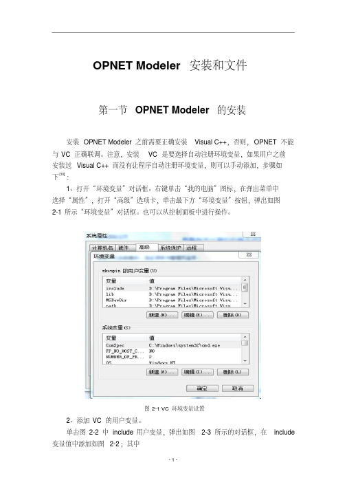
注意,安装VC是要选择自动注册环境变量,如果用户之前安装过Visual C++而没有让程序自动注册环境变量,则可以手动添加,步骤如下[10]:1、打开“环境变量”对话框。
右键单击“我的电脑”图标,在弹出菜单中选择“属性”,打开“高级”选项卡,单击最下方“环境变量”按钮,弹出如图2-1所示“环境变量”对话框。
也可以从控制面板中进行操作。
图2-1 VC环境变量设置2、添加VC的用户变量。
单击图2-2中include用户变量,弹出如图2-3所示的对话框,在include 变量值中添加如图2-2;其中<VC_dir>\VC98\atl\include;<VC_dir>\VC98\mfc\include;<VC_dir>\VC98\include;其中<VC_dir>表示VC的安装目录。
(因个人电脑安装的不同路径也不同)图2-2 变量设置用同样的方式在lib 变量值中添加:<VC_dir>\VC98\mfc\lib;<VC_dir>\VC98\lib;在MSDevDir变量值中添加:<VC_dir>\Common\MSDev98;在path变量中添加:<VC_dir>\Common\Tools\winNT;<VC_dir>\Common\MSDev98\bin;<VC_dir>\Common\Tools\program Files\Microsoft Visual Studio\VC98\bin。
保存已更改的环境变量,退出。
安装OPNET Modeler的操作。
(如图2-3)安装opnet14.5:路径最好默认(1)先装modeler(2)再装models(3)最后装docs(4)双击license maker破解图2-3 安装说明第二节OPNET常用文件格式OPNET仿真能够运行所必须使用的文件可以分为两类[11]:1、以*.m结尾的文件,如*.nt.m、*.pb.m、*.nd.m、*.pr.m、*.seq、*.prj、*.pk.m、*.ic.m等;2、自定义的文件,如*.h、*.ex.c、*.ps.c、*.ex.cpp、*.ps.cpp、*.gdf。
- 1、下载文档前请自行甄别文档内容的完整性,平台不提供额外的编辑、内容补充、找答案等附加服务。
- 2、"仅部分预览"的文档,不可在线预览部分如存在完整性等问题,可反馈申请退款(可完整预览的文档不适用该条件!)。
- 3、如文档侵犯您的权益,请联系客服反馈,我们会尽快为您处理(人工客服工作时间:9:00-18:30)。
Beijing Credit Top Company Co., Ltd.北京怡嘉行科技有限公司OPNET Modeler Training (Day 2)2Beijing Credit Top Co. ,Ltd. All rights reservedCourse Content•DAY 1:•Introduction•Modeling Framework•Features of the Project Editor {Lab}•Node Modeling {Lab}•Process Modeling {Lab}•Other Editors {Lab}•Running The DES•Understanding Statistics •Configure/Run DES •Simulation Log•Viewing Simulation Results •Publishing and Animation •Building a First Network {Lab}•DAY 3:•Traffic Modeling •Modeling Applications with the Standard Application Models{Labs}•Debugging Techniques {Labs}DAY 2:•General Simulation Methodology•Events and Event List Concepts •Process ModelingMethodology (PMM) {Lab}•Parametric Studies{Lab}DAY 4:•Wireless Modeling {Labs}•Modeling Custom WirelessEffects {Labs}Beijing Credit Top Company Co., Ltd.北京怡嘉行科技有限公司General Simulation Methodology4Beijing Credit Top Co. ,Ltd. All rights reserved•Topics–Understanding what you are modeling –Granularity –Defining Data –Results•Conceptual Goals–Use basic methodology for developing a network simulation study.–Plan simulation studies using a consistent method.Agenda5Beijing Credit Top Co. ,Ltd. All rights reservedFlow Diagram: A Simulation StudyYesEnd StartResultsstatisticallyuseful?NoNoResultssufficientlydetailed?Choosing input andrunning simulationsSystem resultsaccurate?Defining input andoutputSpecifying thesystem modelNoChoosing aspectsto be modeledUnderstanding yourgoals for thesimulationUnderstanding thesystem6Beijing Credit Top Co. ,Ltd. All rights reservedUnderstanding the Proposed System•You must understand the proposed system to model it accurately.•The model cannot be more accurate than your understanding.•Recommendation: obtain a written specification of the system you will be modeling.7Beijing Credit Top Co. ,Ltd. All rights reservedUnderstanding Your Goals•What general questions do you want the simulation to answer?•Sample questions:–How much will replacing our Ethernet hub with an FDDI hub increase throughput?–How much does a customized protocol improve efficiency in my cellular network?–How much will adding 1000 users lengthen response time?8Beijing Credit Top Co. ,Ltd. All rights reservedChoosing Aspects to Be Modeled•From the general questions, formulate specific research objectives, such as–Quantifying the throughput at a specific receiver.–Measuring the effect of changing a link’s transmission rate.–Finding the point where traffic load causes the system to become unstable.•These objectives determine the “granularity”(level of detail) required in the model.9Beijing Credit Top Co. ,Ltd. All rights reservedChoosing the Granularity Required•Choose the coarsest granularity that still answers all questions accurately.•Often, some portions of a model require fine granularity, and others much less.•OPNET is flexible --it allows you to vary the granularity within a single model.10Beijing Credit Top Co. ,Ltd. All rights reservedDefining the Data Input and Output•Input may refer to a predefined aspect of the model (such as connectivity) or may be more parametric (such as traffic generation rate).•To study effects on a system, keep most inputs constant and vary one or two over a range.•Determine which output (throughput, ETE delay, etc.) you need and the best presentation method (graphs, tables, animations, etc.)11Beijing Credit Top Co. ,Ltd. All rights reservedOutput may be presented as:graphs,animations,tables, web reportsor numerical values.Defining the Data Input and Output12Beijing Credit Top Co. ,Ltd. All rights reservedSpecifying the System Model•Simulation software can represent your system in many different ways. To use it effectively–Understand the features your simulation software offers.–Understand how those features can best describe your system.13Beijing Credit Top Co. ,Ltd. All rights reservedChoosing a Range of Input•Keep most variables constant except for one or two that you vary over a range.•Usually it is possible to analytically estimate upper and lower bounds for the range.•Choose input values that span this range.•After running initial simulations, you may decide to –Extend the range.–Focus on a narrow range to obtain finer detail.14Beijing Credit Top Co. ,Ltd. All rights reservedChoosing a Range of Input —Example•First range chosen was 2.0 -2.9 Mb/s with step 0.1 Mb/s.•Second range chosen was 2.4 -2.6 Mb/s with step 0.02 Mb/s.First range chosenSecond range chosen15Beijing Credit Top Co. ,Ltd. All rights reservedSystem Results Accurate?•Output should be “sanity-checked”for accuracy and robustness:–Does all output make sense?–Can it be justified?–Does the model behave appropriately?•One technique: predict output first, then compare predicted to actual output.16Beijing Credit Top Co. ,Ltd. All rights reservedResults Sufficiently Detailed?•As needed, either widen the input range to get “the bigger picture”or narrow it to focus on a specific region.•Should you–Collect more or different statistics?–Change the level of granularity?–Model different aspects of your system?17Beijing Credit Top Co. ,Ltd. All rights reservedResults Statistically Useful?•Is the model operating in steady state?–Expect initial transient behavior, converging to steady state.–Look for rising averages, increasing queue lengths, or other output that is still varying. This might mean that the model is not in steady state.18Beijing Credit Top Co. ,Ltd. All rights reserved Results Statistically Useful?•Run simulations for a longerperiod until outputs arestable.•A model that never reachessteady state indicates anunstable system.•Look at various statisticalmeasures to ensure that themodel is in steady state.19Beijing Credit Top Co. ,Ltd. All rights reservedResults Statistically Useful?•Have you run enough simulations?–Run numerous simulations, varying the random number seed and generating confidence intervals.–Run simulations until confidence intervals are tight.Beijing Credit Top Company Co., Ltd.北京怡嘉行科技有限公司Events and EventList Concepts21Beijing Credit Top Co. ,Ltd. All rights reserved Agenda•Conceptual Goals–Events–Interrupts–Event-driven simulation–Event list and the simulation time clock–Simulation Kernel–Processes and interrupts22Beijing Credit Top Co. ,Ltd. All rights reservedEvent-Driven Simulation•An event is a request for a particular activity to occur at a certain time.•OPNET simulations are event-driven. Time, in the simulation, advances when an event occurs.•A different method might be to sample at regular intervals. Disadvantages are as follows:–Accuracy of results is limited by the sampling resolution.–Simulation is inefficient if nothing happens for long periods.23Beijing Credit Top Co. ,Ltd. All rights reservedTime Event Type Module0.0 Initialize src.gen0.0Initialize src.rte4.3Timer expires src.gen4.3Packet arrives src.rteHeadEvent List Concepts•An OPNET simulationmaintains a single globalevent list.•All objects access a sharedsimulation time clock.•Events are scheduled onthe list in time order. Thefirst event on the list is thehead.•An event has dataassociated with it.•When an event completes itis removed from the list.24Beijing Credit Top Co. ,Ltd. All rights reservedInterrupts•An event becomes an interrupt when it reaches the head of the event list and is delivered by the Simulation Kernel to the designated module.•Data associated with the event can be obtained by the module when the interrupt occurs.•Certain modules, processes, and queues can be selected to place initial interrupts on the event list.25Beijing Credit Top Co. ,Ltd. All rights reservedThe Simulation Kernel•An entity, the Simulation Kernel (SK), manages the event list.•The SK delivers each event, in sequence, to the appropriate module.•The SK receives requests from modules and inserts new events on the event list.26Beijing Credit Top Co. ,Ltd. All rights reserved How Does the Event List Work?New event reaches head ofevent list, which causesSimulation Kernel to deliveran interrupt to the appropriatemoduleSimulation Kernel regainscontrol from moduleProcess, within themodule gains controland processesinterruptSimulation Kerneldeletes event fromevent list, allowingnew event to reachhead of list27Beijing Credit Top Co. ,Ltd. All rights reservedEvent List Implementation•The Simulation Kernel uses a proprietary, efficient algorithm to maintain the event list.•Event times are expressed as double-precision, floating point numbers and are used to keep the event list sorted.0.01234 56789 11111 110.01234 56789 11111 220.01234 56789 11111 330.01234 56789 11111 440.01234 56789 11111 550.01234 56789 11111 660.01234 56789 11111 77Suppose that this interrupt triggers an event to occurat 0.01234 56789 11111 75.The Simulation Kernel minimizes the time requiredto place this event at the correct place on the list.28Beijing Credit Top Co. ,Ltd. All rights reservedSimultaneous Events•What Happens When Two Events Are Scheduled for the Same Simulation Time?•The events are actually simulated sequentially, though they appear to occur synchronously according to the time clock.•The Simulation Kernel uses one of two methods to determine execution order:–“Natural order method”: The event that reaches the list first isexecuted first.–“Priority factor method”:Modules and events are assigned priority factors.Events with a higher priority or originating from a higher priority module are executed before events with a lower priority or from a lower prioritymodule.29Beijing Credit Top Co. ,Ltd. All rights reservedEvent List Concepts Reviewed•Some events must be entered on the event list at the start of a simulation.–A generator module enters an initial event.–A processor or queue module has the begsim interruptattribute enabled.•An event list typically has a few events -each event spawns another event or two that is placed on the list as the spawning event is deleted.•The event list is always growing and shrinking.•An event is pending until executed.A pending event can be cancelled.30Beijing Credit Top Co. ,Ltd. All rights reservedDelivery of Interrupts•When an interrupt is delivered to a module, control passes from the Simulation Kernel to the module.•If the module is a queue or processor, the interrupt is delivered to the process running within the module.31Beijing Credit Top Co. ,Ltd. All rights reservedForced States•Forced (green) and unforced(red) states differ significantlyin execution timing.•In a forced state, the process:–Invokes the enter executives–Invokes the exit executives–Evaluates all conditionstatements–If exactly one conditionstatement evaluates to true,the transition is traversed tothe next state.Transition to next stateTransition to next stateForced (green)statesEnter execsinvokedNo blocking or waitingExit execsinvokedEnter execsinvokedExit execsinvokedNo blocking or waiting32Beijing Credit Top Co. ,Ltd. All rights reservedUnforced States•In an unforced state, theprocess–Invokes the enter executives–Places a marker at the middleof the state–Releases control to theSimulation Kernel andbecomes idle–Resumes at the marker andprocesses the exit execswhen next invokedStart of invocationEnd of invocationUnforced (red) statesTransition to next stateBlocking, waitingfor invocationExit execs processedwhen invocationoccursEnter execsinvokedNextinvocationstarts hereBlocking, wait fornext invocation33Beijing Credit Top Co. ,Ltd. All rights reservedTransitions Between States•After completing the exit executives, the process evaluates the condition statements of all departing transitions from the state.•One and only one condition statement must evaluate to true.•The process traverses the transition associated with this condition statement.•A transition with condition = “default”is true if and only if no other conditions are true.•A transition with no condition set is termed unconditional and is always true.34Beijing Credit Top Co. ,Ltd. All rights reservedHow a Process Handles an Interrupt •Flow diagram showing how a process handles an interrupt(except the initial interrupt)Implementexit execsSet marker;block and waitfor interruptReceiveinterrupt EvaluateconditionstatementsRed state?YesFollowtransition tonext stateImplemententer execsFindmarkerNo35Beijing Credit Top Co. ,Ltd. All rights reservedProcess Model Example•Model with three forced states and one unforced state3. Transition occurs. 6. Transitionoccurs.2. Exit execs invoked immediately.Transition condition(pk_count==0)evaluates to true. 5. Exit execs invoked immediately.8. Marker is placedand process stopshere.7. Enter execs invoked.4. Enter execs invoked.1. Initial interrupt delivered and theenter execs invoked.36Beijing Credit Top Co. ,Ltd. All rights reserved Event List Example •Consider the following modelNetwork modelNode modelNode modelNode model: srcNode model: dest1Network model37Beijing Credit Top Co. ,Ltd. All rights reservedEvent List Example•The network model has three nodes (src, dest1,dest2) relying on two node models (both dest nodes use the same node model).•In the src node model, packets are generated at gen and sent by queue to either transmitter (tx0 / tx1).•Packets then flow across a link to a destination node (dest1, dest2) where they are received (rx) and thrown out (sink).•Three modules (gen, queue, and sink), have process models associated with them.38Beijing Credit Top Co. ,Ltd. All rights reservedThe BEGSIM Interrupt•BEGSIM is a special type of interrupt that occurs at simulation time 0.0, before any other type of interrupt.•A BEGSIM interrupt usually initializes a module and schedules future events.•Any processor or queue can have its begsim intrpt attribute enabled, resulting in an event being placed on the event list for time 0.0.39Beijing Credit Top Co. ,Ltd. All rights reservedEvent List Example•The begsim intrpt attribute for gen and sink is enabled; this places two events on the event list.Time Event Type Module0.0BEGSIM src.gen0.0BEGSIM dest1.sink0.0 BEGSIM dest2.sinkNode model40Beijing Credit Top Co. ,Ltd. All rights reservedProcessing the First Interrupt •Consider the process model specified by the gen module.Node model: src Process model: genStarting the Simulation1. To start the simulation, the head of the event list isprocessed and a BEGSIM interrupt is delivered to the process in src.gen.2. Because this is the first interrupt, the process beginsexecution at the initial state, marked with a black arrow. 3. Because this state is being entered, the enter execs are executed.Time0.0 0.0 0.0Event TypeBEGSIM BEGSIM BEGSIMModulesrc.gen dest1.sink dest2.sink41Beijing Credit Top Co. ,Ltd. All rights reservedProcessing the First Interrupt at genProcess model: genProcess model42Beijing Credit Top Co. ,Ltd. All rights reservedProcessing the First Interrupt at gen4. Process invokes and completes the enter execs of Init. 5. Because Init is a forced (green) state, process immediately invokes and completes the exit execs. 6. Process evaluates all condition statements. This state has only one departing transition which evaluates to true. 7. Process transitions to Wait.43Beijing Credit Top Co. ,Ltd. All rights reservedProcessing the First Interrupt at gen8. Process invokes and completes the enter execs of Wait.Process model44Beijing Credit Top Co. ,Ltd. All rights reservedProcessing the First Interrupt at gen9. One action in the enterexecs (line 8) is to schedule a self interrupt by means of a KP. This adds an event to the event list.Time0.0 0.0 0.0 4.3Event TypeBEGSIM BEGSIM BEGSIM SELFModulesrc.gen dest1.sink dest2.sink src.gen10.Process places amarker at the middle of Wait. 11.Process becomes idle.Marker45Beijing Credit Top Co. ,Ltd. All rights reservedProcessing the Second Interrupt at sink12.Simulation Kernel removes the first event and advancesthe next event to the head of the event list. The simulation time remains 0.0.13. Simulation Kernel delivers a BEGSIM interrupt to dest1.sink. 14.Process in sink module gains control. It executes until it reaches an unforced (red) state, places a marker, and then becomes idle. (This model is not shown.)TimeFirst event is removedEvent TypeBEGSIM BEGSIM SELFModuledest1.sink dest2.sink src.gen0.0 0.0 4.346Beijing Credit Top Co. ,Ltd. All rights reservedProcessing the Next Interrupt at gen15.The Simulation Kernel removes the previous event andadvances the next event to the head of the event list. The simulation time becomes 4.3 seconds.16.The event at the head of the list causes a SELFinterrupt to be delivered to the src.gen process. The process resumes at the marker in the middle of Wait.17.Process invokes and completes the exit execs of Wait.Time4.3Event TypeSELFModulesrc.gen47Beijing Credit Top Co. ,Ltd. All rights reservedContinuing the Process at gen18.To leave Wait, the process evaluates all condition statements. This state has one outgoing transition and its condition statement (shown) evaluates to true.48Beijing Credit Top Co. ,Ltd. All rights reservedContinuing the Process at gen19. The process transitions to Send.20. The process invokes the enter execs of Send and calls op_pk_send ( ) to send a packet. This results in an event of type STRM being placed on the event list.Time4.3 4.3Event TypeSELF STRMModulesrc.gen src.queue49Beijing Credit Top Co. ,Ltd. All rights reservedContinuing the Process at gen21. Because Send is a forced (green) state, the processimmediately invokes and completes the exit execs.22. Process evaluates all possible transitions. One evaluatesto true.23. Process transitions to Wait. 24. Process invokes enter execs of Wait , schedules anotherSELF interrupt in the event list and becomes idle. 25. Simulation Kernel takes control and processes the next event on the list.50Beijing Credit Top Co. ,Ltd. All rights reservedSimulation Termination• Simulations terminate in one of four ways–The event list is emptied. –Simulation attribute duration expires. –A process calls for termination, using the KP op_sim_end(). –A fatal error occurs.51Beijing Credit Top Co. ,Ltd. All rights reservedHow Does Time Advance?• Simulation time advances only when an event with a latertime is taken from the event list.• No simulation time occurs during an invocation of a processmodel.• No time elapses during transitions between states.–A process model must always end in a red state so time can advance. –Avoid endless looping between forced (green) states.52Beijing Credit Top Co. ,Ltd. All rights reservedSummary• Forced and unforced states differ in when they execute theirinstructions.• Any processor or queue can have the attribute begsimintrpt enabled, scheduling an event for time 0.0.• Control passes dynamically between the Simulation Kerneland individual processes.53Beijing Credit Top Co. ,Ltd. All rights reservedBreak54Beijing Credit Top Co. ,Ltd. All rights reservedBeijing Credit Top Company Co., Ltd.Process Modeling Methodology (PMM)北京怡嘉行科技有限公司Introduction• What is the Process Modeling Methodology (PMM)?– A systematic approach to creating process models in OPNET Modeler – Quickest, most efficient method of development – Protection from some common pitfalls – Produces consistent results – Indispensable for larger models• But first…What is a Process Model?56Beijing Credit Top Co. ,Ltd. All rights reservedOPNET EnvironmentProcess model is the heart of custom simulation development57 Beijing Credit Top Co. ,Ltd. All rights reservedComparing Approachesgg gggg ggFlower Petal - tcp_manager_v3.pr.mPMM - tcp_conn_v3.pr.mBoth of these are parts of the standard OPNET TCP modelBeijing Credit Top Co. ,Ltd. All rights reserved58Process Model DynamicsinitINITIALIZED MSG1msg1 gMSG2connectCONNECTEDREGISTEREDregisterFAIL FAILwaitMSG3msg2 gFAILRECOVERfailBeginners avoid RED states, but they are very important!59msg3 gBeijing Credit Top Co. ,Ltd. All rights reservedStates, Events, and ActionsImportant definitionsStateEventActionStateAlarmasleep/WakeupawakeCondition of system0:0060Stimulus to move system6:00InstantaneousResponse of system to stimulus6:00Condition of systemTime progressesTime progresses8:00Beijing Credit Top Co. ,Ltd. All rights reservedSteps for Building a Process Model• Obtain protocol specification • Design using the methodology • Review design • Implement in OPNET61Beijing Credit Top Co. ,Ltd. All rights reservedProcess Modeling Methodology Stages• First four stages: Design– Stage 1: Context definition – Stage 2: Process level decomposition – Stage 3: Enumeration of events (per process) – Stage 4: Event Response Table development (per process)This is an iterative stage and is the meat of process model methodology4 1 2 3• Last stage: Implementation in OPNET– Stage 5: Specification of process actions (per process)562Beijing Credit Top Co. ,Ltd. All rights reservedProcess Modeling Methodology Example 1: Stop-and-Wait Retransmission Protocol• Protocol for the Data Link Layer at the sending side only • Basic functionality: Provide reliable communications over alossy channel• Accept frames from the upper layer and send them to thephysical layer63Beijing Credit Top Co. ,Ltd. All rights reservedProcess Modeling Methodology Example 1: Protocol RequirementsAmalgamated Communications Kompany (ACK) C. R. Ash SWaRe Protocol Version 1.3.X Aug 23, 2005 ProprietaryReceive frames from higher layer Transmit frame over physical layer Must receive an acknowledgment before sending the next frame Queue frames arriving from the higher layer if the process is waiting for acknowledgment for a previous frame Retransmit the frame if an acknowledgment is not received before the end of a timeout period When the link fails, frames cannot be sent or retransmitted until the link recoversBeijing Credit Top Co. ,Ltd. All rights reserved64Just for Fun…How many lines of OPNET code are needed to model this protocol?65Beijing Credit Top Co. ,Ltd. All rights reservedStage 1. Context Definition• Fit this piece into the big picture: • Step 1: Identify interdependent modules • Step 2: Select communication mechanisms withinterdependent modules4 1 2 3• Step 3: Develop diagram of system andinterdependent modules566Beijing Credit Top Co. ,Ltd. All rights reservedStage 1: Context Definition (cont.)1 2 3Higher LayerFrames for Transmission4SWaRe ProtocolTransmitted Frames AcknowledgementsPhysical Layer567Beijing Credit Top Co. ,Ltd. All rights reservedStage 2: Process-Level Decomposition• Step 1: Determine which process modeldecomposition technique is applicable to the system– Single process model – Multiple (parent-child) process models1 2 3• Step 2: If a multi-process implementation is chosen,identify the areas of responsibility assigned to each process4• Step 3: For multi-process implementations, determinecircumstances of process creation and which process will be the root568Beijing Credit Top Co. ,Ltd. All rights reservedStage 3: Enumeration of Events• Step 1: Define logical events of each process • Step 2: Select event implementation methods1 2 34 Frames for TransmissionAck timeoutSWaRe Protocol! !System - Link Fail System - Link Up 5Acknowledgements69Beijing Credit Top Co. ,Ltd. All rights reservedStage 3: Enumeration of Events (cont.)Event Name Event Description Interrupt Type1 2 34570Beijing Credit Top Co. ,Ltd. All rights reservedStage 3: Enumeration of Events (cont.)Event Name Frame Arrival Event Description Interrupt Type A frame has arrived Stream from the higher level. The retransmission timer has expired. Self4 1 2 3Timeout Acknowledgement Received! !An Stream acknowledgement for the last transmitted frame has been received. The link has failed. The link has recovered. The process starts. Failure Recovery Begin Simulation5Link Fail Link Up Power Up71Beijing Credit Top Co. ,Ltd. All rights reservedStage 4: Event Response Table Development• The Event Response Table specifies how the model reactsto various events, depending upon the state of the modelState Event Condition Action Final State1 2 34• The events and actions are indicated in the specification • What are the conditions? • What are the states?72 Beijing Credit Top Co. ,Ltd. All rights reserved5ConditionsState Event Condition Action State73Beijing Credit Top Co. ,Ltd. All rights reservedStage 4: Event Response Table Development - Identifying States• A state…– Represents a blocking point of the process – Corresponds to particular sequences of events having occurred – Reacts to events in a specific manner – Is mutually exclusive of and complementary to other states4 1 2 3• Problem:– Typically we do not know all possible states of the system at this point in the design process5• Solution:– Start with an initial state and “walk” through the model74 Beijing Credit Top Co. ,Ltd. All rights reservedStage 4: Event Response Table Development: Iteration Plan - Start With Initial State• Step 1: Choose a state–Step 2: Choose an eventStep 3: Choose a condition under which the event occurso Step 4: Determine all actions to perform o Step 5: Determine the final state1 2 3Loop Step 3 for all conditions–Loop Step 2 for all events4• Loop Step 1 until all states are completeState InitBeijing Credit Top Co. ,Ltd. All rights reservedEventConditio Action nFinal State575Stage 4: Event Response Table Development - Initial StateUsing a BEGINSIM interrupt assures that the Init state will not have to handle any other type of event 1 2 3State InitEvent Frame ArrivalConditio nActio nFinal State4Timeout Acknowledgeme nt Received Link Fail Link Up Power Up765AlwaysNoneIdleBeijing Credit Top Co. ,Ltd. All rights reserved。
