TMQ100A中文资料
11 TQ-100型同期继电器

TQ-100型同期继电器带通、整流和低通滤波,然后相加, 再进行电平检测,经反相器进入与门2, 作为相位比较回路的闭锁条件。
令U X为额定值,U M<U X,则U X–U M >0,电平检测比较电压为U B+。
U M>U X,则U X–U M <0,电平检测比较电压为U B-。
设|U B+|=|U B-|=U B当|U X– U M|≤U B时, 电平检测经反相器输出“1”态至与门2, 不起闭锁作用。
当|U X– U M|>U B时, 电平检测经反相器输出“0”态至与门2, 起闭锁作用,使继电器不动作;3.3 继电器出口回路当|U X - U M|≤U B和的幅值差在允许范围内,电平检测经反相器输出“1”态。
当|U X– U M|>U B M和X的幅值差超出允许范围,电平检测经反相器输出“0”态。
只有相位差ΔФ≤180°-ФZ和幅值差|U X– U M|≤U B两条件同时满足时,与门2才输出“1”态,经驱动回路作用于出口,继电器动作。
有一个条件不满足,继电器不能动作。
4 技术条件4.1 环境基准条件环境温度:20±2℃相对湿度:45%~75%大气压力:86~106KPa4.2 正常使用条件环境温度:-10℃~+50℃环境相对湿度:不大于90%大气压力:86~110KPa储存和运输过程中的极限温度:-25℃~+70℃使用地点的海拔高度:不大于2500米使用环境的周围介质无爆炸危险;不含有腐蚀性气体;所含导电尘埃的浓度不应使绝缘水平降低到允许极限值以下。
可靠的供电电源。
4.3 额定参数额定交流电压:100V;100/ 3 V额定频率:50HZ辅助直流电源额定电压:220V;110V;48V4.4 特性参数整定范围 级差 返回系数 整定值误差动作值温度变差相位差ΔФ 10°~ 178° 0.2° ≤1.05 ≤±4% ≤±1.5%/10℃U X– U M>0时,≥0.95≤±1% U N≤±1.5%/10℃电压差U B5%U N~ 10%U N连续U X– U M<0时,≤1.05动作时间和返回时间:在电压差U B为0,相位差为ΔФZ/1.5情况下测试,动作时间不大于50mS,返回时间不大于20mS。
TM100SZ-M中文资料

ABSOLUTE MAXIMUM RATINGSUnit V V V V V VNON-INSULATED TYPEM 400480320400480320Symbol V RRM V RSM V R (DC)V DRM V DSM V D (DC)ParameterRepetitive peak reverse voltage Non-repetitive peak reverse voltage DC reverse voltageRepetitive peak off-state voltage Non-repetitive peak off-state voltage DC off-state voltageUnit A A A A 2s A/µs W W V V A °C °C N·m kg·cm N·m kg·cm gConditionsThree-phase, half-wave, T C =122°C One half cycle at 60Hz, peak value Value for one cycle of surge current V D =1/2V DRM , I G =1.0A, T j =150°CMain terminal screw M5Mounting screw M6Typical valueRatings 155********.7 × 104505.00.5105.02.0–40~+150–40~+1251.47~1.9615~201.96~2.9420~30160Symbol I T (RMS)I T (AV)I TSM I 2t di/dt P GM P G (AV)V FGM V RGM I FGM T j T stg——ParameterRMS on-state current Average on-state currentSurge (non-repetitive) on-state current I 2t for fusingCritical rate of rise of on-state current Peak gate power dissipation Average gate power dissipation Peak gate forward voltage Peak gate reverse voltage Peak gate forward current Junction temperature Storage temperatureMounting torqueWeight Voltage classELECTRICAL CHARACTERISTICSUnit mA mA V V/µs V V mA °C/W °C/WLimitsSymbol I RRM I DRM V TM dv/dt V GT V GD I GT R th (j-c)R th (c-f)ParameterRepetitive peak reverse current Repetitive peak off-state current On-state voltageCritical rate of rise of off-state voltage Gate trigger voltage Gate non-trigger voltage Gate trigger current Thermal resistance Contact thermal resistanceTest conditionsT j =150°C, V RRM applied T j =150°C, V DRM appliedT j =150°C, I TM =300A, instantaneous meas.T j =150°C, V D =2/3V DRM T j =25°C, V D =6V, R L =2ΩT j =150°C, V D =1/2V DRM T j =25°C, V D =6V, R L =2ΩJunction to case (per 1/3 module)Case to fin, conductive grease applied (per 1/3 module)Min.———200—0.2515——Typ.—————————Max.30301.15—3.0—1000.20.3NON-INSULATED TYPENON-INSULATED TYPE。
100A全数字MPPT太阳能充电控制器
Tel: 0755-25336126
七. 面板及接线图
八. 前面板操作说明
8.1. 显示参量说明
充电控制器可以实时显示蓄电池的“电流”、“电压”、“功率”和“剩余电量百分比”, 以及 4 组太阳能电池板各自的“电流”、“电压”和“功率”。
“电流”参量显示蓄电池的充电电流或太阳能电池板的输出电流,单位是安(A)。 “电压”参量显示蓄电池或者太阳能电池板的端电压,单位是伏(V)。 “功率”参量显示蓄电池的充电功率或太阳能电池板的输出功率,单位是瓦(W)。 “蓄电池剩余电量百分比”参量显示蓄电池剩余的电量的百分比。 所有显示都是只读不可调整设置。
14.5V
29V
58V
120 S (默认)
2.7 S
10 Bit
10 Bit
10 Bit
0.4 mW
0.8 mW
1.6 mW
20 mV
40 mV
80 mV
30 mA
30 mA
30 mA
0.1W
0.2W
0.4W
0.1%
0.1%
0.1%
1200BPS, 2400BPS, 4800BPS, 9600BPS
Shenzhen Qingchi Technology Co., LTD
E-mail: kirby@
Tel: 0755-25336126
100A 全数字 MPPT 太阳能充电控制器
一.产品简介
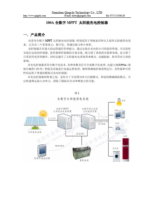
该系列全数字 MPPT 太阳能充电控制器,特别适用于智能家居和无人值班太阳能供电设 备。它具有三个重要优点:数字化,带通信能力和小体积。
最大充电电流可达25A X 4 = 100A。 4. 每路太阳能板输入通道的MPPT运算都是独立控制的,某一路太阳能板被遮阴或者失效不
派利斯TM振动变松保护表中文手册

派利斯电子(北京)有限公司用户手册TM系列振动变送保护表地震式传感器->壳振涡流探头->轴位移涡流探头->轴振涡流探头->转速目录TM系列振动变送保护表的介绍I.旋转机械监测和保护的发展II.新功能III.通用特点系列振动变送保护表选项TM101机壳振动速度、加速度、位移变送保护表I.概述振动变送保护表的技术参数III.订货选项.IV.现场接线图V.现场报警调试VI.现场操作标定(仅专业工程师操作)TM201轴振动保护表I.概述振动变送表技术说明III.订货选项.IV.现场接线图V.现场安装VI.现场操作标定(专业工程师操作)TM202轴振动保护表I.概述轴位置变送表技术说明III.订货指南IV.现场接线图V.安装VI.现场操作VII.标定程序(专业工程师操作) TM301振动变送监测表I.概述振动变送表技术说明III.订货指南.IV.现场接线图.V.现场安装VI.现场操作标定(专业工程师操作)TM302位移变送保护表I.概述轴位置变送表技术说明III.订货指南.IV.安装V.现场接线图.VI.现场操作VII.标定程序(专业工程师操作) TM401双线轴振动变送表I.概述振动变送表技术指标III.订货指南IV.现场接线图.V.现场安装VI.现场操作标定TM402双线轴位置变送表I.概述技术指标III.订货指南.IV.现场接线图.V.现场安装VI.现场操作VII.标定程序(专业工程师操作) TM501转速/键相变送监测表I.概述振动变送表技术指标III.订货指南IV.现场接线图.V.现场安装VI.现场操作VII.标定步骤TM900电源变换器I.概述技术指标TM0200单通道显示器I.技术指标II.定货指南:TM系列振动变送保护表的介绍I.旋转机械监测和保护的发展旋转机械监测的概念是二战以后由军方实验室推广而来,研究表明机械的故障严重影响生产,振动保护和状态监测的研究从50年代初至今已经得到完善的发展。
TM-100PR-HB Operation Manual RevL.1 CN (TE14-1138)
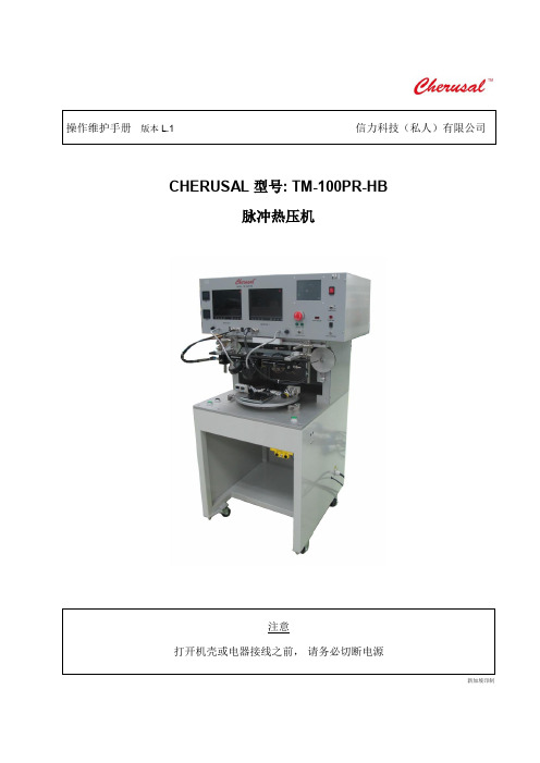
CHERUSAL 型号: TM-100PR-HB脉冲热压机新加坡印制型号TM-100PR-HB操作维护手册目录第 1 章 : 产品概述 (1)加热方法 (1)机器部件和特性 (1)规格 (2)桌台尺寸 (4)下压气缸 (4)压头装置 (5)热压头 (6)热电偶 (6)热电偶接口 (6)工作台 (7)水平调节 (7)视图系统 (8)变压器 (8)硅胶带装置 (8)真空发生器 (9)主供气单元 (10)输入按钮 (10)控制面板 (11)第 2 章 : 安装要求 (14)气源 (14)环境 (14)安全 (14)第 3 章 : 产品安装和使用 (15)机器安放位置 (15)包装 (15)开机 (16)用户界面 (16)快速启动 (17)功能键 (18)生产 (19)参数 (19)工程 (26)手动 (30)错误信息 (32)加热错误 (32)SCR卡报警 (32)超温 (32)硅胶报警 (32)密码恢复 (32)操作工序 (33)第 4 章 : 校正 (35)温度校正 (35)触摸屏校正 (37)第 5 章 : 产品维护 (38)热压头 (39)变压器电缆线 (39)真空 (40)夹具 (40)安装 (40)热压头保养 (40)水平调节 (40)电源 (41)气源 (41)保存 (41)安全标示 (41)接地标志 (41)PE标志 (41)有害电压标示 (42)夹伤或割伤标示 (42)高温标示 (42)第 6 章 : 故障排除 (43)第 7 章 : 电图 (46)第 8 章 : 气图 (49)信力科技(私人)有限公司成立于1995年,主要设计和制造一系列标志为品牌的精密热能应用设备,如ACF预贴机,脉冲式热压机,回流焊接机,COG/COF邦定机等。
目前,信力的销售网络已扩展至亚洲区域如台湾,中国,香港,马来西亚和菲律宾等。
协同信力机械,信力科技的目标是通过完善的世界销售网络将符合世界水准的产品和服务准时送交给我们的客户。
IQ100电子功率表高端性能管理介绍说明书

High-end power management performanceI Q 100 Electronic Power MeterIntroductionWith energy costs skyrocketing,you need the ability to verifythe accuracy of utility billingand allocation of energy costsamong business units, differentmanufacturing areas or facilities,and tenants. Production equip-ment and IT systems arevulnerable to power anomalies;therefore, you must ensure thatpower is always up to specifica-tions. If your infrastructure isan established facility, you mayhave addressed these concernsin the past by deploying avariety of analog gauges andmeters—one for volts, onefor amperes and so on, withseparate meters for eachmeasurement.If you’re planning an upgradeor new power infrastructure,no doubt you would like tocapitalize on the latest tech-nology to improve upon thatcumbersome architecture andits patchwork view.T ypical applications•Utility and commercialmetering•Substations, industrialfacilities, power generationsites and campuses• Submetering•Load studies and voltagerecording•Analog meter replacementFeatures and benefits•Measure and display real-time information about criticalpower parameters with asampling rate of 400 samplesper cycle•Monitor power utilization andquality with ANSI C12.20accuracy (0.5 percent)•Verify meter accuracy withoptional test pulse self-certification capabilities•Available as transducer onlyor with display•Optional Modbus® RTU orModbus TCP communications•Prepared for the future—the meters are designedto accommodate firmwareupgrades and capabilities•Integrate into Eaton’s PowerXpert® Architecture for aholistic system-level viewHigh-end capabilities youwould not expect from anultra-compact meterProviding the first line of defenseagainst costly power problems,Eaton’s IQ 100 electronic powermeters can perform the work ofan entire wall of legacy meteringequipment utilizing today’s tech-nology. Eaton’s IQ 100 metersuse 24-bit AD converters thatsample at more than 400samples per cycle and meetANSI C12.20 standards foraccuracy of 0.5 percent. Withsuch high-performance measure-ment capability, these meterscan be confidently used forprimary revenue metering andsubmetering applications.Eaton’s IQ 100 meters providedirect-reading metered valuesfor the most critical poweraspects, such as watts, wattdemand, watthours, voltage-amperes (VA), VA-hours, vars,varhours and power factor.They have high samplingspeed and accuracy.Is the utility company billingaccurately? The IQ 100 modelsprovide a traceable watthour testpulse (used with a watthour pulserecorder or totalizer), so you canverify the accuracy of your meterand, in turn, the accuracy of bill-ing from the utility company andto internal customers.The meters are designed tointegrate into Eaton’s PowerXpert Architecture for end-to-end management of your entirepower system, giving you aholistic system-level view.Industry-standard communication protocolsIQ 100 meters use the optional Modbus protocol. This industry-standard protocol provides serial communications with Eaton or third-party platforms, such as a building-management system, power-management system or Eaton’s Power Xpert Gateway for Web-based monitoringas part of Eaton’s Power Xpert Architecture.Integrated with Eaton’s Power Xpert ArchitectureIQ 100 meters integrateinto Eaton’s Power Xpert Architecture, where meters, gateways and monitoring devices collaborate to createa unified, centralized view of the end-to-end power and facility infrastructure.When used in this architecture and in conjunction with Eaton’s Power Xpert Gateway, IQ 100 meters with the Modbus RTU option can provide Web-based graphics of current power condi-tions. Simply connect your meter to a Power Xpert Gateway to translate Modbus-based information from the meter into HTML-based Web pages that are accessible from any standard Web browser. If you select a model with the RJ45 option,the meter can easily be moni-tored remotely via Power Xpert Software or another third-party monitoring system. With access to accurate, real-time information from IQ 100 meters, the Power Xpert Architecture can transform your power system into an integrated, agile system, and an easily managed entity that performs better and costs less.Designed for the userWhen space is at a premium, yet you need ANSI C12.20 accuracy, Eaton IQ 100 meters fit the bill. These ultra-compact meters are ideal for electrical equipment assemblies, machine control panels (such as panel-board and switchboard mains and feeders), low voltage metal-enclosed switchgear feeders and motor control centers. Requiring far less space than other meters with similar functionality, IQ 100 meters fit into a standard ANSI or IEC cutout on a panel-board or other electrical equipment and, therefore, fit easily into retrofit applications. Most meters in this class have small or dark displays that can be hard to see, especially from a distance. Eaton’s IQ 100 meters have a large, bright red, three-line LED display, each line more than a half-inch tall. This display is very easy to read, even if the meter is installed at a heightor distance. Using the keypad and menus on the local display, users can display a variety of electrical system values or program the meter (see IQ 100 Meter Faceplate Display on page 3). The IQ 100 meters can also be configured remotely using the Eaton configuration software provided withthe meter.In addition, the meters are available with or without the display module. Y ou might choose to forego the display for applications where there is no need to configure or read the meter locally. This option reduces costs, especially where many meters will be monitored from a central operations system.Features of IQ 100 Electronic Power MetersIQ 100 Meter (Rear View) with Connection and Communication PortsRJ45 Rear View2EATON CORPORATION Eaton’s IQ 100 electronic power meterThe Reading Type indicator shows what type of information you’re viewing, such as minimum/maximum. The Parameter Designator shows the parameter being displayed, such as volts, amps, frequency, power or energy.These lights show how loaded the circuit is, from 10 to 100 percent, relative to the programmed maximum.The watthour test pulse is used to verify the accuracy of the meter.Twhich varies between low- and high-voltage applications.Configurable Auto Scroll can display all key values in turn or show a fixed display.IQ 100 Meter Faceplate DisplayI Q 100 Meter Dimensions IQ 100 Meter Ordering Information4.85(123.2)IQ 100M Side ViewIQ 100T Side View5.02(127.5)3.25 (82.6) 3.54(89.9)4.93 (125.2)4.16 (105.7)IQ 100M Front View3EATON CORPORATION Eaton’s IQ 100 electronic power meterotee:N Specifications are subject to change without notice and representthe maximum capabilities of the product with all options installed. This isnot a complete feature list. Features and functionality may vary dependingon selected options, firmware version and product model. Please refer toUser Manual for detailed specifications.IQ 100 Electronic Power Meter T echnical InformationEaton CorporationElectrical Sector1111 Superior Ave.Cleveland, OH 44114United States877-ETN-CARE (877-386-2273)/meters© 2011 Eaton CorporationAll Rights ReservedPrinted in USAPublication No. PA02601008E / TNSeptember 2011Eaton and Power Xpert are registeredtrademarks of Eaton Corporation.All other trademarks are property of theirrespective owners.。
TQLM100a平面回转筛和FMZ-278型多功能家用磨面机价格

磨面机型号:FMZ-278型动力:7.5kw、四极
(三相、380V)产量:小麦粉:200-300公斤/小时(85%出粉率率);玉米粉:220-450公 斤/小时(95%出粉率);豆类粉:200-300公 斤/小时(95%出粉率);薯干粉:200-250公 斤/小时(100%出粉率);本机适用于农村加 工户、城镇小型面粉加工厂加工小麦、玉米、 豆类、高梁、谷物、薯干等粮食成粉,并能加 工精饲料、食盐等。产品特点:FMZ-278磨
面机面粉加工过程中都要经过高速、高温两个 过程,把部分维
厂家洞联网
市场价格
246榨榨油机参数
产品特点及功能描述机体均采用优质板材;轮 毂的前面做成圆弧形有利于气体的导流,减少 涡流的产生,减少动力的消耗;风机叶轮经动 平衡实验,运转平稳,无振动;高中低压离心 通风机广泛应用于工业、农业、矿山、隧道通 风。冷冻、建筑、化工、纺织、面粉厂及饲料 加工厂等各种行业的通风除尘、气体输送粒料 和粉状物料系统。技术参数设备名称型号吸 风量(m3/min)风压(Pa)功率(kw)咼压离心 风机6-41-NO7.5-7.814
厂家洞联网
市场价格
力小,油质纯正,一机多用,可对芝麻、花 生、菜籽、大豆、油葵、胡麻等20多种油料 进行油品加工。 传统榨油机方式的弊端:原始 坊、设备简陋、操作笨重、占地面积大、耗能 高、出油率低,卫生环境差。该榨油机的优 势:设计先进、性能可靠、操作简捷、维护方 便。其主2至3个百分点,每加 工百斤花生米平均可多出2-6斤,全年经济效 益十分可观。节能--同等产量降低电功率40%,以平均每小时节约6度电计算,日生产 可节约3
厂家洞联网
市场价格
585自动液压香油机和多功能全
自动榨油机价格
Amana GCVM 97% ECM Counter Flow Furnace 商品说明书
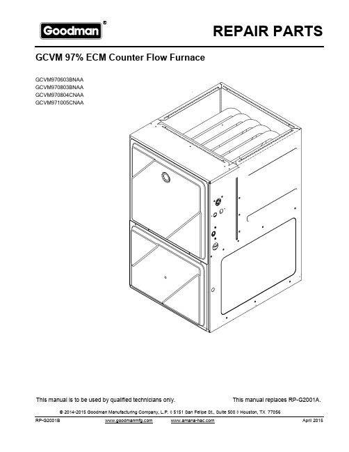
REPAIR PARTS® nufacturing Company, L.P. ◊ 5151 San Felipe, Suite 500 ◊RP-G2001BThis manual is to be used by qualified technicians only.This manual replaces RP-G2001A.April 2015GCVM 97% ECM Counter Flow Furnace© 2014-2015 Goodman Manufacturing Company, L.P. ◊ 5151 San Felipe St., Suite 500 ◊ Houston, TX 77056GCVM970603BNAA GCVM970803BNAA GCVM970804CNAA GCVM971005CNAAImportant Information For assistance within the U.S.A. contact:Goodman Company, L.P.For assistance outside the U.S.A. contact:IndexFunctional Parts List Rev B: updates primary limit controlsIllustration and Parts......................................................................................................................................................................................................Views shown are for parts illustrations only, not servicing procedures AR - As Required NA - Not Available NS - Not Shown00000000 - See NoteQTY - Quantity Example (QTY 3) (If Quantity not shown, Quantity = 1)M - Model Example (M1) (If M Code not shown, then part is used on all Models)Text Codes:ExampleM1 - Model#1 M2 - Model#2 M3 - Model#3Expanded Model Nomenclature:Goodman Manufacturing Company, L.P. is not responsible for personal injury or property damage resulting from improper service. Review all service information before beginning repairs.Warranty service must be performed by an authorized technician, using authorized factory parts. If service is required after the warranty expires, Goodman Manufacturing Company, L.P. also recommends contacting an authorized technician and using authorized factory parts.Goodman Manufacturing Company, L.P. reserves the right to discontinue, or change at any time, specifications or designs without notice or without incurring obligations. 2Consumer Affairs DepartmentGoodman Manufacturing Company, L.P.7401 Security Way Houston, Texas 77040877-254-4729-Telephone 713-863-2382-FacsimileInternational DivisionGoodman Manufacturing Company, L.P.7401 Security Way Houston, Texas 77040713-861-2500-Telephone 713-863-2382-Facsimile 4 - 113RP-G2001BFunctional PartsPartNo:Description:20162904*PRIMARY LIMIT-TEMPERATURE CONTROL(M2)*Refer to service bulletin SF-0540130F00038AUX LIMIT - LT BLUE 120º (QTY 2)0163F00017BECKETT BURNER (QTY 3)0271F00161BLOWER SHELL & WHEEL ASSY (M3, M4)0271F00159BLOWER SHELL & WHEEL ASSY (M1, M2)0130F00393DATA, FURNACE PCB (M1)0130F00394DATA, FURNACE PCB (M2)0130F00395DATA, FURNACE PCB (M3)0130F00396DATA, FURNACE PCB (M4)0130F00010FLAME SENSOR0151M00024GAS VALVE0257F00282HEAT EXCHANGER ASSY. (M2)0257F00284HEAT EXCHANGER ASSY. (M4)0257F00311HEAT EXCHANGER ASSY. (M1)0257F00312HEAT EXCHANGER ASSY. (M3)0130F00008IGNITOR-SINI 17 SEC0130M00141INDUCTOR, 5.9 AMPS (GMPE100-4) (M3, M4)0130M00243INTERLOCK SWITCH10123529MANUAL RESET R.O.S. LIMIT (QTY 2)0131M00272MOTOR, 1 HP, SERIAL ECM (M4)0131M00270MOTOR, 1/2 HP, SERIAL ECM (M1, M2)0131M00271MOTOR, 3/4 HP, SERIAL ECM (M3)0171M00003MOTOR-ID, BLOWERPCBKF202PCB, FURNACE CONTROL20162901PRESSURE LIMIT-RED (M3)0130F00481PRESSURE SWITCH (-.1 (COL BOX))0130F00482PRESSURE SWITCH (-.17 /-.86) (M1, M2, M3)0130F00483PRESSURE SWITCH (-.17 /-.86) (M4)0130F00036PRIMARY LIMIT - PINK (M1, M4)0130M00140TRANSFORMER 120V TO 24V, 40VASPECIAL PARTS0161F00000P GOODMAN NAMEPLATEExpanded Model NomenclatureM1 - GCVM970603BNAAM2 - GCVM970803BNAAM3 - GCVM970804CNAAM4 - GCVM971005CNAARP-G2001B 3Cabinet 4RP-G2001BCabinetRef. No:PartNo:Description:Ref.No:PartNo:Description:Image 1:GASKET (QTY 2)0154F00024111GASKET (QTY 2)0154F00025121DOOR, ACCESS 17.5 PNT (M1, M2)0121F00291DG191DOOR, ACCESS 21 PNT (M3, M4)0121F00292DG191DOOR, BLOWER 17.5 PNT (M1, M2)0121F00288DG201DOOR, BLOWER 21 PNT (M3, M4)0121F00289DG201VIEW PORT BUSHING-BLOWER DOOR (QTY 2)B1392139281GASKET, DECK (M1, M2)0154F00020311GASKET, DECK (M3, M4)0154F00021311PIPE, STRAIGHT CF (QTY 2)0161F00064441PIPE GROMMETM0501301451BUTTON PLUGM0570808491BUTTON PLUGM0570806501PLUG, HOLE0161M00027521HOSE CLAMP (QTY 2)0163M00049611UNIVERSAL BUSHING UB 875B1392104741BUTTON PLUG (QTY 2)M0310345NSBUTTON PLUGM0570807NSCF DRAIN TUBE ASSY (M1, M2)0270F03125NSCF DRAIN TUBE ASSY (M3, M4)0270F03126NSCF DRAIN TUBE ASSY (M1, M2)0270F03514NSCF DRAIN TUBE ASSY (M3, M4)0270F03515NSDRAIN TRAP0161F00046NSGOODMAN NAMEPLATE0161F00000PNSSCREW-DECORATIVE (QTY 3)M0209730NSImage 2:DRAIN PART BAG ASSY CF0270F0314112BAG ASSY CF0270F0313922Expanded Model NomenclatureM1 - GCVM970603BNAAM2 - GCVM970803BNAAM3 - GCVM970804CNAAM4 - GCVM971005CNAA5 RP-G2001B Blower Assembly 6RP-G2001BBlower AssemblyRef.No:Part No:Description:Ref.No:Part No:Description:Image 1:BLOWER SHELL & WHEEL ASSY (M1, M2)0271F0015931BLOWER SHELL & WHEEL ASSY (M3, M4)0271F0016131BLOWER MOTOR GROMMET (M3, M4)A400270261MOTOR MOUNT BAND (M1, M2)0121M00038141MOTOR MOUNT BAND (M3, M4)10441601141MOTOR MOUNT ARM (M3, M4)10441501151MOTOR MOUNT ARM (M1, M2)B1376857151MOTOR, 1 HP, SERIAL ECM (M4)0131M00272181MOTOR, 1/2 HP, SERIAL ECM (M1, M2)0131M00270181MOTOR, 3/4 HP, SERIAL ECM (M3)0131M00271181TC SCREW (M3, M4)M022*******TC SCREW 1.25" (M1, M2)M025*******MACHINE SCREW (M3, M4)M0267144251MACHINE SCREW HWH 1/4-20 X 1-1/2 BZ (M1, M2)B1393323251WASHER, FLAT 1/4 ID X 1 OD (M1, M2)B1392918261WASHER-FLAT (M3, M4)M027*******KEPS NUT (M3, M4)M028*******LOCKNUT, NYLON, INSERT 1/4, 20 (M1, M2)B1393800281TRANSFORMER 120V TO 24V, 40VA0130M00140381INDUCTOR, 5.9 AMPS (GMPE100-4) (M3, M4)0130M00141391PCB, FURNACE CONTROL PCBKF202401COVER, CONTROL BOARD0161F00014411CONTROL MOUNT PANEL0121F00094461AUX LIMIT - LT BLUE 120º (QTY 2)0130F00038521SLIT LOCK WASHER (M3, M4)B1392820621CONTROL HARNESS0259F00040NS DATA, FURNACE PCB (M1)0130F00393NS DATA, FURNACE PCB (M2)0130F00394NS DATA, FURNACE PCB (M3)0130F00395NS DATA, FURNACE PCB (M4)0130F00396NS PLASTIC PLUG, 1" (2713-BLK) (QTY 4)B1392021NS POWER HARNESS HIGH VOLTAGE 0259F00041NS WIRE HARNESS-BLOWER0259F00024NS*If end bells are needed please order the following: 0131M00182 - 1/2 HP 0131M00183 - 3/4 HP 0131M00184 - 1 HPExpanded Model Nomenclature M1 - GCVM970603BNAA M2 - GCVM970803BNAA M3 - GCVM970804CNAA M4 - GCVM971005CNAA7RP-G2001B Chassis 8RP-G2001BChassisRef. No:PartNo:Description:Ref.No:PartNo:Description:Image 1:PAINTED BASE PAN-21" C (M3, M4)0121F00435DG11PAINTED BASEPAN-17.5" CF (M1, M2)0121F00427DG11DECK-BLOWER, 17.5" CF (M1, M2)0121F0042531DECK-BLOWER, 21" CF (M3, M4)0121F0043331INSULATION, HT EXCHANGER 17.5" (M1, M2)0160F0001591INSULATION, HT EXCHANGER 21" (M3, M4)0160F0001691ANGLE, DECK (M1, M2)0121F00314101ANGLE, DECK (M3, M4)0121F00315101TOP, PAINTED FURNACE 17.5" CF (M1, M2)0121F00426DG111TOP, PAINTED FURNACE 21" CF (M3, M4)0121F00434DG111ANGLE, SIDE (QTY 2)0121F00313121GASKET-FA (M1, M2)20179309151GASKET-FA (M3, M4)20179310151INSULATION-BACK 17.5" (M1, M2)0160F00012161INSULATION-BACK 21" (M3, M4)0160F00013161INSULATION, SIDE (QTY 2)0160F00018171HARNESS-WIRING0159F0005018125" PRESSURE SWITCH HOSES (M3, M4)0164M00029191PRESSURE SWITCH HOSE (M1, M2)0164M00012191HOSE-PRESSURE SW 6"0164M00019201INTERLOCK SWITCH0130M00243221ELBOW-FLUE, 17.5" CFLOW (M1, M2)0164F00003241ELBOW-FLUE, 21" CFLOW (M3, M4)0164F00004241MOTOR-ID, BLOWER0171M00003271COUPLING0161F00037281PRESSURE SWITCH (-.1 (COL BOX))0130F00481291PRESSURE SWITCH (-.17 /-.86) (M1, M2, M3)0130F00482301PRESSURE SWITCH (-.17 /-.86) (M4)0130F00483301JUNCTION BOX PLA0161F00042311JUNCTION BOX LID0161F00043331PLUG-TUBEM0326804701GASKET (QTY 2)0154F00015791GASKET (M1, M2)0154F00014811GASKET (M3, M4)0154F00016811BRACKET, DOOR SWITCH0121F00389991PRESSURE SWITCH HOSE (M3, M4)0164M00008NSExpanded Model NomenclatureM1 - GCVM970603BNAAM2 - GCVM970803BNAAM3 - GCVM970804CNAAM4 - GCVM971005CNAA9 RP-G2001B Heat Exchanger / Manifold / Gas Valve 10RP-G2001BHeat Exchanger / Manifold / Gas ValveRef. No:PartNo:Description:Ref.No:PartNo:Description:Image 1:IGNITOR-SINI 17 SEC0130F0000811GAS VALVE0151M0002421ORIFICE (QTY 3)0163F0000431FLAME SENSOR0130F0001041MANUAL RESET R.O.S. LIMIT (QTY 2)1012352951MANIFOLD (M1)0163F0000861MANIFOLD (M3)0163F0000961MANIFOLD (M4)0163F0001061MANIFOLD (M2)0163F0001461BECKETT BURNER (QTY 3)0163F0001771BRACKET-BURNER 3 (M1)0121F0045581BRACKET-BURNER 4 (M2, M3)0121F0045481BRACKET-BURNER 5 (M4)0121F0045381ORIFICE BRACKET-BURNER 3 (M1)0121F00458111ORIFICE BRACKET-BURNER 4 (M2, M3)0121F00457111ORIFICE BRACKET-BURNER 5 (M4)0121F00452111COVER, FRONT (M4)0161F00027131COVER, FRONT (M2)0161F00031131COVER, FRONT (M1)0161F00056131COVER, FRONT (M3)0161F00065131GASKET, FRONT (M1, M2)0154F00011141GASKET, FRONT (M3, M4)0154F00012141HEAT EXCHANGER ASSY. (M2)0257F00282151HEAT EXCHANGER ASSY. (M4)0257F00284151HEAT EXCHANGER ASSY. (M1)0257F00311151HEAT EXCHANGER ASSY. (M3)0257F00312151TUBE PLUGM0326804161CAP-VINYL .500A1781105231COVER, REAR (M1, M2)0121F00317261COVER, REAR (M3, M4)0121F00318261GASKET, REAR CVR (M1, M2)0154F00037271GASKET, REAR CVR (M3, M4)0154F00038271*PRIMARY LIMIT-TEMPERATURE CONTROL (M2)20162904371*Refer to service bulletin SF-054PRESSURE LIMIT-RED (M3)20162901371PRIMARY LIMIT - PINK (M1, M4)0130F00036371PRIMARY LIMIT-HEAT SHIELD0121F00439NSSHIELD, COIL (QTY 2)0121F00355NSExpanded Model NomenclatureM1 - GCVM970603BNAAM2 - GCVM970803BNAAM3 - GCVM970804CNAAM4 - GCVM971005CNAA11 RP-G2001B 。
Eaton IQ 100系列电子功率计产品简介说明书

IQ 100 Series Electronic Power MetersGeneral DescriptionThe IQ 100 meter family provides capabilities youwould not normally expect in affordable, compactmeters, such as fast sampling rate and accuratemetering for a full range of power attributes.Providing the first line of defense against costlypower problems, Eaton®’s IQ 100 series electronicpower meters can perform the work of an entirewall of legacy metering equipment utilizing today’stechnology.When space is at a premium, yet you need ANSIC12.20 accuracy, the IQ 100 series fit the bill.These meters are ideal for electrical equipmentassemblies, machine control panels, such as pan-elboard and switchboard mains and feeders, lowvoltage metal-enclosed switchgear feeders andmotor control centers. Requiring far less spacethan other meters with similar functionality, IQ100 series fit into a standard ANSI or IEC cutouton a panelboard or other electrical equipment, andtherefore fit easily into retrofit applications.Typical Applications• Utility and commercial metering.• Substations, industrial facilities, powergeneration sites and campuses.• Sub-metering.• Load studies and voltage recording.• Analog meter replacement.Features and Benefits• Measure and display real-time information aboutcritical power parameters with a sampling rateof 400 samples per cycle.• Monitor power utilization and quality with ANSIC12.20 accuracy (0.5 percent).• Verify meter accuracy with KYZ test pulse self-certification capabilities.• Optional Modbus® RTU or TCP communications.• Available as transducer only or with display.• Designed to accommodate upgrades.• Integrate into Eaton’s Power Xpert®Architecture for a holistic system-level view.2Technical Data TD02601015ESeptember 2011IQ 100 Series Electronic Power Meterseaton corporation /metersAdditional FeaturesT able 1. Features of IQ 100 Electronic Power MetersFeaturesIQ 130IQ 140IQ 150InstrumentationCurrent, per Phase •••Current Demand •••Calculated Neutral Current •••Voltage, per Phase (L-L, L-N)•••Min/Max. Readings, I, V•••Min./Max. Readings, I, V, PF, F, W, VAR, VA ••Frequency••PowerReal, Reactive and Apparent Power, Total (W, VAR, VA)••Power Factor, Total••Real, Reactive and Apparent Power Demand••Demand MethodsBlock Interval (Sliding, Fixed)••EnergyReal, Reactive and Apparent Energy, Total (Wh, VAR, VAh)•CommunicationsRS-485, Modbus RTU, Modbus ASCII, KYZ Output Opt.Opt.Opt.RJ45, Modbus TCP , KYZ OutputOpt.Opt.Opt.IQ 100T Transducer OnlyFigure 1. IQ 100 Meter Dimensions — Front and SideViewsIQ 100M Front ViewIQ 100M Side ViewIQ 100T Side ViewIQ 100 Meter Dimensions3Technical Data TD02601015ESeptember 2011IQ 100 Series Electronic Power Meterseaton corporation /meters Technical Data and SpecificationsT able 2. IQ 100 Electronic Power Meter T echnical InformationDescriptionSpecificationsCurrent InputsClass 10 5 Amp Nominal, 10 Amp Max.Class 21 Amp Nominal,2 Amp Max.Fault Current Withstand 100 Amps for: 300 Amps for: 500 Amps for:10 Seconds 3 Seconds 1 SecondContinuous Current Withstand 20 Amps for Screw Terminated or Pass-through Connections Programmable Current Full Scale to Any CT RatioBurden 0.005 VA per Phase Max. at 11 Amps Pickup Current Class 10 Class 20.1% of Nominal 5 mA 1 mAConnectionsPass-through Wire Gauge Dimension Quick Connect0.177 Inches (4.5 mm)0.25-Inch Male TabVoltage InputsRangeLine-to-Neutral Line-to-Line20 – 416 Vac 20 – 721 VacProgrammable Voltage Range Full Scale to Any PT RatioSupported Systems 3 Element Wye, 2.5 Element Wye,2 Element Delta, 4-Wire Delta Systems Input Impedance 1 Meg Ohm/PhaseBurden 0.36 VA/Phase Max. at 600 V;0.014 VA at 120 VoltsConnection7-Pin 0.400-Inch Pluggable Terminal Block, AWG #12 – 26 (0.129 – 3.31 mm 2)IsolationAll inputs and outputs are galvanically isolated to 2500 volts.Environmental RatingsOperating Temperature -20°C to +70°C Storage Temperature -20°C to +70°COperating Humidity To 95% RH Non-condensing Faceplate RatingNEMA 12 Water-resistant Mounting Gasket IncludedDescriptionSpecificationsSensing MethodVoltage, Current True RMSPowerSampling at Over 400 Samples per Cycle On All ChannelsUpdate RateWatts, VAR and VA 100 msec at 60 Hz All other parameters1 second at 60 HzPower Supplyac/dc Voltage Option 90 – 265 Vac at 50/60 Hz or100 – 370 Vdc, Universal ac/dc Supply dc Voltage Option 18 – 60 Vdc Burden10 VA Max.Optional Communications FormatConnection Type RS-485 or RJ45 (Through Back Plate)Com Port Baud Rate 9600 – 57,600 Bauds Com Port Address01 – 247Data Format 8-Bit, No Parity ProtocolsModbus ASCII, RTU, TCPOptional KYZ PulseContacts1 Form A On Resistance, Max.35 Ohms Peak Switching Voltage 350 Vdc Continuous Load Current350 mA (10 ms)Off-state Leakage Current at 350 Vdc 1 uA Opto-isolation3750 VacDimensions and ShippingWeight 2 lbs.Basic UnitH 5.00 x W 4.90 x L 5.00 Inches IQ 100Mounts in 92 mm DIN and ANSI C39.1 Round Cut-outs Shipping Container Dimensions 6-Inch CubeTolerance+/-0.1 Inches (2.54 mm)ComplianceIEC 6870.5% Accuracy ANSI C12.200.5% Accuracy ANSI C62.41BurstUL/cUL/CEElectrical and Electronic Measuring and Test Equipment 22CZotee:N These specifications are subject to change without notice and represent the maximum capabilities of the product with all options installed. This is not a complete feature list. Features and functionality may vary depending on selected options, firmware version and product model. Please refer to the technical data sheet and User Manual for detailed specifications.Technical Data TD02601015ESeptember 2011IQ 100 Series Electronic Power MetersEaton Corporation Electrical Sector 1111 Superior Ave.Cleveland, OH 44114United States877-ETN-CARE (877-386-2273)/meters © 2011 Eaton Corporation All Rights Reserved Printed in USA TD02601015E / TN September 2011Eaton, Modbus and Power Xpert areregistered trademarks of Eaton Corporation. All other trademarks are property of their respective owners.Ordering InformationT able 3. IQ 100 Meter Catalog Numbering SystemDescriptionCatalog Number Panel Mounting Adapter for retrofitting an IQ 100 to an IQ Analyzer/IQ DP-4000/IQ Data CutoutIQ250-PMAKT able 4. IQ 100 Meter AccessoriesIQ 150 M A 6 5 1 1Model Series130 = Volts/Amps 140 = Power 150 = EnergyMeter TypeM = Meter (with integral display)T = Transducer Only (no display)Frequency5 = 50 Hz System6 = 60 Hz SystemCurrent Input1 = 1 Amp Secondary 5 = 5 Amp SecondaryPower Supply1 = 90–265 Vac/dc 4 = 24–48 VdcCommunication0 = None1 = Modbus and KYZ Output (RS485)2 = Modbus TCP and KYZ Output (RJ45)。
单相整流桥MDQ100A

杭州西整电力电子科技有限公司符号参数测试条件结温Tj (℃)参数值单位最小典型最大I O 直流输出电流三相全波整流电路,T c =100℃150100A V RRM 反向重复峰值电压V RRMtp=10msV RsM =V RRM +200V 150120016001800V I RRM 反向重复峰值电流V RM =V RRM1505mA I FSM 通态不重复浪涌电流10ms 底宽,正弦半波150 1.50KAI 2t 浪涌电流平均时间积V R =0.6V RRM1507.20103A 2SV FO 门槛电压0.80V r F 斜率电阻150 4.50m ΩV FM 正向峰值电压I FM =100A251.151.3V R th(j-c)热阻抗(结至壳)180°正弦半波,单面散热0.2℃/W R th(c-h)热阻抗(结至散)180°正弦半波,单面散热0.07℃/W V iso 绝缘电压50HZ ,R.M.S ,t=1min I iso :1mA(max)2500V F m 安装扭矩(M5)安装扭矩(M6)与散热器固定4.0±15%5.0±15%N ·m N ·m T sbg 储存温度-40125℃W t 质量170gOutlineM340、M342attribute data :■芯片与底板电气绝缘,2500V 交流绝缘■采用德国产玻璃钝化芯片焊接,优良的温度特性和功率循环能力■体积小,重量轻typical application :■变频器■交直流电机控制■各种整流电源I O100AV RRM 1200~1800V I FSM 1.50KA I 2t7.20103A 2S杭州西整电力电子科技有限公司模块外型图、安装图matters needing attention:1、模块实际负载电流大于5A时务必要加装散热器,需提供良好的通风条件。
100Ah产品规格书 100Ah Product Specification说明书

100Ah 产品规格书Product Specification of 100Ah Cell电芯型号Cell Model : 001CB270 电芯容量Cell Capacity : 100Ah修改记录目录Content0术语定义Definitions (4)1适用范围Scope of application (5)2产品电性能指标Electrical specification (5)2.1概要General (5)2.2充电模式/参数Charging/Parameter (6)2.3放电模式Discharging (7)2.4低温容量Low Temperature Capacity (7)3安全与可靠性Safety and Reliability (7)4产品寿命终止管理Product End of Life Management (7)5应用条件Application Conditions (8)6安全防范Safety Precautions (10)7免责声明Disclaimer (11)5风险警告Risk Warning (13)8电芯图纸Mechanical Drawing (15)0术语定义 Definitions术语 Terms 定义 Definition1. 适用范围 Scope of application本技术协议详细描述了CATL 生产的3.2V 100Ah 储能用磷酸铁锂电池的产品性能指标以及产品使用条件及风险警示。
The purpose of this document is to specify the specifications of 100Ah 3.2V lithium iron cells for energy storage system with CATL (“Product”) to be supplied by CATL.2. 产品电性能指标 E lectrical specification2.2.8其他充电条件(模式) C-Rate Other charge Condition (C-Rate)3.安全与可靠性 Safety and Reliability3.1使用条件说明:安全测试、寿命测试、系统成组设计需要施加预紧力,新鲜电芯的预紧力范围为2000N~5000N,全生命周期受力范围为2000N~15000N。
Extech TM100数字J K类温度计说明书
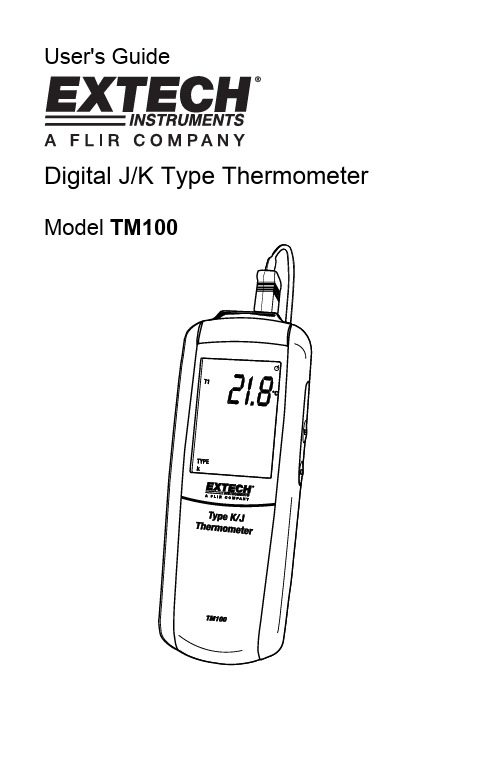
User's GuideDigital J/K Type Thermometer Model TM100IntroductionCongratulations on your purchase of the Extech TM100 Digital Thermometer with K/J single-type input. This meter is shipped fully tested and calibrated and, with proper use, will provide years of reliable service.SafetyTo prevent personal injury or meter damage, use the meter only as specified in this guideMeter DescriptionMeter1. Thermocouple input connector2. Function buttons (Power, Enter, C-F-K)3. Function buttons (Hold, MAX/MIN, Set)4. LCD display5. Battery compartmentDisplay1. Setup2. Offset option3. Hold mode4. Auto power off5. Upper display T1 reading6. Temperature units7. Lower display (max, min,avg, offset value of T1)8. Max, Min and Average9. Time display10. K/J type thermocouple11. Low BatteryOperationConnecting thermocouples1. This meter accepts any K/J-type thermocouple with spade lugs (sub-miniature typewith one spade wider than the other).2. Plug the thermocouple into the meter's thermocouple input jack.Measuring1.thermometer will display the first temperature reading (upper display).C-F-K button to select the desired temperature unit of measure. Athe2. Pressdisplay icon will reflect the selection.3. Contact the object to be measured with the probe. Read the measured temperaturein the display.Note: If the display indicates “OL” the temperature is outside the measurementrange. The display shows "- - - -" when a thermocouple is not connected.MAX/MIN/AVG modePress MAX/MIN to capture and step through the maximum (MAX), minimum (MIN) and average (AVG) temperature values. These values will be shown in the lower display with an elapsed time reference below (hrs:mins , mins:sec).1. Press MAX/MIN to enter this mode.2. Press MAX/MIN to step through maximum, minimum and average readings.3. Press MAX/MIN for 3 seconds to return to normal mode.Data HoldPress the HOLD button to freeze the reading in the display. HOLD will appear at the top right of the display. Press the HOLD button again to return to normal operation mode. BacklightPress SETUP button to turn backlight off/on.Setup optionThe setup option is used to change the thermocouple type, to turn the sleep mode off/on and to adjust the thermocouple offset.Note: In the setup mode, the upper display shows menu items and lower display shows settings.SET button for 3 seconds to enter or exit setup. When the thermometer1. Presstheis in Setup mode, the display shows SETUP.Set Type J or K thermocouple1. Press ▲ or ▼to scroll to the “TYPE” setting (shown bottom left).2. Press ENTER to choose the option.3. Press ▼ to toggle between J and K.4. Press the SET button for 3 seconds to save the setting and return to normal mode.Set Sleep/Non-sleep modeThe thermometer enters sleep mode by default. The meter will automatically shut off after 20 minutes if no button press occurs for 20 minutes. When the thermometer is in Setup mode, the display shows SETUP.1. Press▲ or ▼to scroll to the “SLP” setting.ENTER to chose the option “On” or “OFF” will appear in the display.2. Press▼ to select on or off..3. Press4. PressENTER to store the new setting in memory.SET button for 3 seconds to return to normal mode.5. PressSet OffsetUse the offset option in Setup (T1menu item) to adjust the thermometer’s readings to compensate for known temperature offset at a specific temperature. The allowableadjustment range is ± 5.0°C or ± 9.0 °F.1. Plug the thermocouple into the input connector.2. Place the thermocouple into the known, stable temperature environment (such as aice bath or dry well calibrator). Allow the reading to stabilize.3. Press▲ or ▼to scroll to the “T1” option and press ENTER.4. Change the offset temperature reading (upper display) by pressing ▼until itreaches the desired temperature.SET button for 3 seconds to return to normal mode.5. PressReplacing the Batteries1. Turn off the thermometer.2. Loosen the screw and remove the battery door.3. Replace the AAA batteries.4. Replace the battery door and tighten the screw.Support line (781) 890-7440 TechnicalSupport:Extension200;E-mail:******************Repair&Returns:Extension210;E-mail:*****************Product specifications subject to change without notice For the latest version of this User Guide, Software updates, and other up-to-the-minute product information, visit our website: Extech Instruments Corporation, 285 Bear Hill Road, Waltham, MA 02451 SpecificationsTemperature Range:K type thermocouples-200°C to 1372°C (-328°F to 2501°F) J type thermocouples-210°C to 1100°C (-346°F to 2012°F) Temperature accuracy:T1 Above –100 0C (-148 0F)± [0.15%rgd+1°C (1.8°F)] T1 Below –100 0C (-148 0F)± [0.5%rgd+2°C (3.6°F)] Display Resolution:0.1°C /°F /°K <1000, 1°C /°F /°K >1000 Battery: “AAA “1.5V×3Operating Temperature:0°C to +50°C (40°F to +122°F) Storage Temperature:−10°C to +50°C (14°F to +122°F) Dimensions:8.7 x 2.5 x 1.1” (220 x 63 x 28mm) Weight:7oz (200g) WarrantyEXTECH INSTRUMENTS CORPORATION (A FLIR COMPANY) warrants this instrument to be free of defects in parts and workmanship for one year from date of shipment (a six month limited warranty applies to sensors and cables). If it should become necessary to return the instrument for service during or beyond the warranty period, contact the Customer Service Department at (781) 890-7440 ext. 210 for authorization or visit our website for contact information. A Return Authorization (RA) number must be issued before any product is returned to Extech. The sender is responsible for shipping charges, freight, insurance and proper packaging to prevent damage in transit. This warranty does not apply to defects resulting from action of the user such as misuse, improper wiring, operation outside of specification, improper maintenance or repair, or unauthorized modification. Extech specifically disclaims any implied warranties or merchantability or fitness for a specific purpose and will not be liable for any direct, indirect, incidental or consequential damages. Extech's total liability is limited to repair or replacement of the product. The warranty set forth above is inclusive and no other warranty, whether written or oral, is expressed or implied.Calibration and Repair ServicesExtech offers repair and calibration services for the products we sell. Extech also provides NIST certification for most products. Call the Customer Care Department for information on calibration services available for this product. Extech recommends that annual calibrations be performed to verify meter performance and accuracy.Copyright © 2009 Extech Instruments Corporation (a FLIR company)All rights reserved including the right of reproduction in whole or in part in any form.。
KIRAY 100无接触红外热量计说明书
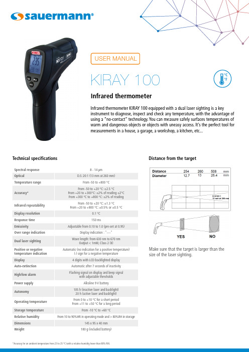
Infrared thermometer KIRAY 100 equipped with a dual laser sighting is a keyinstrument to diagnose, inspect and check any temperature, with the advantage of using a “no-contact” technology. You can measure safely surfaces temperatures of warm and dangerous objects or objects with uneasy access. It’s the perfect tool formeasurements in a house, a garage, a workshop, a kitchen, etc...*Accuracy for an ambient temperature from 23 to 25 °C (with a relative humidity lower than 80% RH).Technical specificationsDistance from the targetMake sure that the target is larger than the size of the laser sighting.Modes flow chart Description13452342 - IR sensor (infrared)3 - Up button4 - Down button5 - Mode button34512341 - Output laser sighting2 - Trigger3 - Set technical unit(°C/°F)4 - Battery compartmentKiray 100 buttons1 – Up button: It allows to incrementemissivity and high/low alarm thresholds.This button also allows in measurementmode to activate or deactivate the laser.2 – Mode button: It allows to navigatethrough the modes (emissivity, lock, highemissivity and high/low alarm thresholds.This button also allows in measurementmode to activate or deactivate thebacklight.2123Display1 – Technical unit °C/°F2 – Low battery indicator3 – Emissivity value = 0.95 (factory setting)4 – Max temperature indicator.5 – Temperature value6 – Current measurement indicator7 – HOLD indicator (fixed measurement)8 – Laser in operation indicator9 – Lock indicator (continuous measurement)10 – High alarm symbol (fixed: activated alarm;flashing + beep: alarm thresholds exceeded)11 – Low alarm symbol (fixed: activated alarm;flashing + beep: alarm thresholds exceeded)Settings before taking measurementBefore measuring temperature, it is recommended to set the technical unit: °C or °FTo set this parameter, open the battery door by pushing on both sides of the trigger. It is not necessary to disconnect the battery to make this setting.• Set the technical unit Set the selector unit to °Cor °F with a mand buttons Trigger• Turning on the device.• ENT pressed: activation of the laser sighting andtemperature measurement.• ENT released: display is on HOLD (HOLD fixed), and gives the last measurement. Display stays on for 7 seconds. If no buttons are activated and if continuous measurement is inactivated, the instrument turn off after 7 seconds.Operating mode• Press ENT trigger to turn on the instrument. Thebacklighted screen, indicating the temperature, and the laser turn on.• Keep ENT pressed. Place the laser sighting at the center of the area to be measured.• Release ENT.• Read the displayed temperature. (Disaply stays on for 7 seconds after the last manipulation).• HOLD appears at the top left of the screen; measurement stays displayed.• Press UP button ta activate or deactivate the laser;• Press DOWN button to activate or deactivate the backlight. Mode button• Allows to define types of desired measurement:emissivity, lock, high alarm, low alarm by pressing as many time on this button.• EMS: when KIRAY100 instrument is turned on, press MODE button, ε flashes. Set emissivity by pressing on UP button to increment it or DOWN button to decrement it. By default, emissivity is set on 0.95. To back to measurement mode, press ENT button; press MODE button to go to next mode.• Lock: when KIRAY100 instrument is turned on, press MODE button twice, the lock indicator at the top of the screen flashes and OFF is displayed. Press UP or DOWN button to put the lock ON.Press MODE button to go to next mode, or press once ENT button: KIRAY100 instrument takes continuous measurements. To cancel lock mode, press once ENT button.• High alarm: when KIRAY100 instrument is turned on, press 3 times MODE button to set high alarm. ON or OFF flashes, press UP or DOWN button to activate or deactivate it (ON or OFF).Press MODE button, high alarm temperature is displayed and high alarm indicator flashes, press UP button to increment it or DOWN button to decrement it.To return to measurement mode, press ENT button; press MODE button to go to next mode.• Low alarm: whenKIRAY100 instrument is turned on, press 5 times MODE button to set low alarm. ON or OFF flashes, press UP or DOWN button to activate or deactivate it (ON or OFF).Press MODE button, low alarm temperature is displayed and low alarm indicator flashes, press UP button to increment it or DOWN button to decrement it.To return to measurement mode, press ENT button; press MODE button to go to next mode.EmissivityEmissivity is a term used to describe the energy-emitting characteristics of materials.Most (90% of typical applications) organic materials and painted or oxidized surfaces have an emissivity of 0.95 (pre-set in the unit).Inaccurate readings will result from measuring shiny or polished metal surfaces.To compensate; cover the surface to be measured with masking tape or flat black paint.Allow time for the tape to reach the same temperature as the material underneath it.Measure the temperature of the tape or painted surface.See table below for values of emissivity of specificmaterials:N T a n g – K I R A Y 100 – 29/10/18 – N o n -c o n t r a c t u a l d o c u m e n t - W e r e s e r v e t h e r i g h t t o m o d i f y t h e c h a r a c t e r i s t i c s o f o u r p r o d u c t s w i t h o u t p r i o r n o t i c e.MaintenanceTo install or change the 9V battery, open the part near the trigger and put it in the battery compartment.Important informationFor correct measurements:• Do not take any measurement on metal or shiny or reflective surfaces.• Do not measure through transparent surfaces such as glass, for example.• Water vapor, dust, smoke, etc... may prevent correct measurements because they obstruct the optical of the instrument.• Make sure that the target is larger than the size of the laser sighting.To avoid any inconvenience:• Do not aim directly or indirectly (reflection on reflective surfaces) the laser in the eyes.• Change the batteries when the indicator blinks.• Do not use the thermometer around explosive gas, vapor or dust• Do not leave the device with the lock on (lock at the top right of the screen) because in this configuration, the instrument does not turn off automatically.To prevent damage on your instrument or equipmentplease carefully respect these conditions:CE certificationThis device meets with following standards’ requirements:EN 61326-1: 2013 and EN 61326-2: 2013Infrared thermometer, how does it work?Infrared thermometers can measure the surface temperature of an object. Its optic lens catches theenergy emitted and reflected by the object. This energy is collected and focused onto a detector. This information is displayed as temperature. The laser pointer is only usedto aim at the target.Accessories• Case holster with passer-by belt • User manual。
Victron Energy ET112单相最大100A能量表手册说明书

Energy Meter ET112 manual1. Introduction and usageThis document is the manual for the single phase max 100 A Energy Meter.The Energy Meter can be used for four things:Grid meter, and used as control input for an ESS System (1).1.2.Measure the output of a PV Inverter3.Measure the output of a AC GensetThe meter is connected to the Color Control GX. There are two options in its wiring: 1.Direct connection, either using the RS485 to USB interface with 1.8m cable length, or the 5.0m cable.2.Wireless connection via ZigbeeVictron part number REL300100000 is the ET112-DIN.AV01.X.S1.X from Carlo Gavazzi. And that is the model we keep in stock.Other ET112 models from Carlo Gavazzi can also be used, as the communication is the same.2. AC WiringConfiguration OptionsGrid Meter - Wiring when used as a grid meter. PV Inverter - Wiring when used to measure PV inverter or AC Genset.This configuration option of either Grid Meter, or PV Inverter is set in the GX device. That selection will effect how the system should be wired, and how the information received from the meter is displayed on the screen.Example DiagramIn this example configuration, a single ET112 is configured as a Grid Meter and will measure the grid import/export of an ESS system with a AC PV inverter. While the exact production of the AC PV inverter will not be seen, this is still a useful configuration as it allows the AC PV production to firstflow to the non-essential loads on that same circuit.A surplus will be used to charge the batteries (seen as export and tried to reduce to grid setpoint eg 0).A deficiency will trigger a discharge of the batteries (seen as import, and tried to reduce to gridset point).This can be useful if the Victron ESS system is installed as a retrofit to an existing AC Solar inverter installation with some larger loads that aren't wired through the Multiplus.If you wanted to see PV production separately you could use the “single phase dual function mode” of the ET340.3. Connection to CCGXOption A: wireless Zigbee connectionStep 1.Connect the Zigbee to USB converter to the CCGX using the supplied USB cable. A few seconds after connecting, the active LED should be on and the TX/RX LED should be blinking (the converter takes its power from the CCGX, so the CCGX needs to be switched on as well).Step 2.Connect the Zigbee to RS485 converter to the ET112 energy meter:Zigbee Converter Energy meterGND Terminal 6A Terminal 4B Terminal 5Make sure only one Zigbee device is powered up right now: the Zigbee to USB converter connected to the CCGX. Power down all others. If you don't do this, the Zigbee to RS485 converter may be connected permanently to another Zigbee device.Step 4.Connect the 12V DC power supply to the Zigbee to RS485 converter. When the power is switched on, check the LEDs again.Option B: Wired connection to CCGXConnect the Energy Meter to the CCGX using the USB to RS485 cable. The RS485 to USB interface cable between the CCGX and the Energy Meter can be extended up to 100 meters; make sure that the extensions of the Data+ (orange) and Data- (yellow) wires form a twisted pair.RS485 Converter Energy meterYellow (Data-)Terminal 5Orange (Data+)Terminal 4Black (GND)Terminal 6The red, green and brown wire coming out of the USB to RS485 cable are not used. Note: You can wire on a RJ45 plug which can plug into the front of either RJ45 socket of the Energy meter, it has the same pin out.3. ConfigurationAfter proper connection and powering up, the meter will be visible on the CCGX in the Settings →Energy Meters menu:The menu lists every meter found. And in the gray box at the right side it shows the configured function.After selecting a meter, see its detailed settings:4. Multiple ET112 Meters in one systemTo connect multiple Energy Meters, wire each meter to a separate RS485-USB converter. Which are then each plugged into a separate USB socket on the CCGX. See NOTE 1 BelowConnecting multiple ET112 meters to the same RS485-USB cable is not possible: the ET112 meter has no display and its Modbus address can therefor not be changed.Note 1 You can connect the ET112 in parallel, just need to change the MOD address to anothernumber using the Configuration software from the supplier which is free from Carlo Gavazzi Web site. DISQUSView the discussion thread.。
tm-1001标准
tm-1001标准一、介绍TM-1001标准是一项有关产品质量和性能的指导性措施。
本标准根据国际标准化组织的相关要求进行制定,旨在帮助企业确保产品的一致性和可靠性。
本文将介绍TM-1001标准的背景、适用范围和主要内容。
二、背景在全球市场竞争日益激烈的背景下,产品质量和性能成为企业取得竞争优势的关键。
为了确保产品符合一定的质量标准,提高产品的可靠性和稳定性,国际标准化组织制定了一系列的标准。
TM-1001标准就是其中之一,它旨在为企业提供一种有效的产品管理方法。
三、适用范围TM-1001标准适用于各类产品的制造和供应过程。
无论是工业产品还是消费品,只要企业期望以高质量和高性能的产品满足市场需求,TM-1001标准都能够为其提供有效的指导。
四、主要内容1.质量管理体系:TM-1001标准要求企业建立健全的质量管理体系,包括明确的质量目标和流程控制,以确保产品的质量一致性。
2.产品设计和开发:本标准强调产品设计和开发阶段的重要性。
企业应该采取科学的方法进行产品设计,并进行严格的测试和验证,以确保产品的性能符合预期。
3.供应链管理:企业在供应链管理方面也需要遵循TM-1001标准的要求。
这包括与供应商建立稳定的合作关系,保证原材料和零部件的质量符合要求。
4.生产过程控制:本标准强调对生产过程中的关键环节进行有效控制。
企业应该建立合理的生产工艺,并采取相应的控制措施,确保产品的一致性和稳定性。
5.质量检测和控制:TM-1001标准要求企业建立完善的质量检测和控制机制。
这包括严格的检测标准和方法,以及及时的纠正和预防措施,确保产品的质量符合要求。
6.持续改进:本标准鼓励企业实施持续改进。
通过对产品和过程的不断优化,企业能够提高产品性能和质量,提升竞争力。
七、结论TM-1001标准是一项有关产品质量和性能的重要指导性标准。
它为企业提供了一种整体的质量管理方法,帮助企业确保产品的一致性和可靠性。
通过遵循TM-1001标准,企业能够提高产品的质量和性能,提升竞争力,取得更好的经济效益。
TMQ400A资料

TMQ100A~1000A Features♦Highly reliable Hall Effect device♦Compact and light weight♦Fast response time♦Excellent linearity of the output voltage over a wide input range ♦Excellent frequency response (> 50 kHz)♦Low power consumption (16 mA nominal)♦Capable of measuring both DC and AC, both pulsed and mixed ♦High isolation voltage between the measuring circuit and the current-carrying conductor (AC2.5KV)♦Extended operating temperature range♦Flame-Retardant plastic case and silicone encapsulate, using UL classified materials, ensures protection against environmental contaminants and vibration over a wide temperature and humidity range Applications♦U PS systems♦P rocess control devices♦A C and DC servo systems♦M otor speed controller♦E lectrical vehicle controllers♦I nverter-controlled welding machines♦G eneral and special purpose inverters♦C ontroller for traction equipment e.g. electric trainsSpecificationsParameter Symbol Unit TMQ100ATMQ200ATMQ300ATMQ400ATMQ500ATMQ600ATMQ800ATMQ1000ANominal Input Current I fn ADC 100 200 300 400 500 600 800 1000 Linear Range I fs ADC ±300 ±600 ±900 ±1200 ±1500 ±1800 ±2400 ±3000 Nominal Output Voltage V hn V 4 V±1% at If=I fn ( R L=10kΩ)Offset Voltage V os mV Within ±15 mV @ I f=0, T a=25°COutput Resistance R OUTΩ <10ΩHysteresis Error V oh mV Within ±10 mV @ I f=I fn→0Supply Voltage V CC/V EE V ±15V±5%Linearity ρ% Within ±0.5% of I fnConsumption Current I CC mA ±16 mA nominalResponse Time (90%V hn) T rμsec 3μsec max. @ d I f/dt = I fn / μsecFrequency bandwidth (-3dB) f BW Hz DCto50kHzThermal Drift of Output - %/°C Within ±0.05 %/°C @ I fnThermal Drift of Zero Current Offset - mV/°C Within ±1 mV/°C @ I fnDielectric Strength - V AC2.5KV X 60 secIsolation Resistance @ 1000 VDC R IS MΩ >500MΩOperating Temperature T a °C -15°Cto80°CStorage Temperature T s °C -20°Cto85°CMass Wg 240gAppearance, dimensions and pin identificationAll dimensions in mm ±0.2, holes –0, +0.2 except otherwise noted.。
TM系列超低压全自动交流稳压器1适用范围

>>让 电 尽 其 所 能A-377 TM 系列超低压全自动交流稳压器 TM系列超低压全自动交流稳压器是一种采用数字集成电路组成取样控制系统,控制电磁继电器,改变自耦变压器的抽头,从而达到输出电压稳定的稳压器。
产品的突出优点是具备输入超低压稳压和实现输入电压宽范围稳压的功能。
本产品广泛适用于各个行业的办公设备以及家用冰箱、冰柜、电风扇、空调、彩电、电脑等电器,适用于通迅、医疗、照明系统等用电场所。
特别适合部分因电网电压过高或过低而造成电器无法正常工作的地区,能自动调整电压到合适范围以保证电器的正常使用。
符合标准:Q/ZT 648。
1 适用范围TM- □额定容量,kVA 自耦调压阶跃型稳压器3.1 环境温度:-5℃~+40℃。
3.2 相对湿度:不大于95%(温度为+25℃)。
3.3 安装地点的海拔高度不超过2000m。
3.4 工作环境:安装环境无明显污秽,无化学性沉积、污垢、有害侵蚀性介质及易燃、易 爆气体的室内。
3.5 安装场所周围应保持通风,安装周围应留足够的散热空间(一般预留空间应≥0.5m), 严禁用塑料罩、布等易燃物品罩住稳压电源或在上面放置杂物,以免引起稳压电源过 热损坏。
3.6 安装时严禁将它放在冰箱、冰柜等家电的塑料构件上,以免稳压器过载发热使家电塑 料面受热变形。
2 型号及含义3 正常工作条件和安装条件让 电 尽 其 所 能 >> A-378配电电器互感器、稳压器类A配电电器4 主要参数及技术性能5 产品特点6 外形及安装尺寸5.1 采用继电器快速切换调压,具有工作可靠,反应速度快,无波形畸变及瞬间过载能力 较强的特点。
5.2 较强的防过载、过压能力,当负载过重时具有自动保护,切断输出电源的功能;当电网电压超过稳压器输入范围而输入高电压时,也能迅速切断输出,确保用户的用电设备安全。
5.3 有效输入电压范围为交流130V-270V,当电网电压从130V至270V范围内变化时,其输出电压始终维持在220V±10%以内,因此特别适宜于电网电压在此范围内波动的 场合下使用。
tm1001标准

TM1001标准是一种用于测试和评估材料性能的国际标准。
它由国际标准化组织(ISO)制定,旨在为各种行业提供一个统一的测试方法,以确保材料的质量和性能符合特定的要求。
这个标准涵盖了许多不同类型的材料,包括金属、塑料、橡胶、陶瓷等。
TM1001标准主要包括了以下几个方面:1. 测试方法:TM1001标准提供了一系列详细的测试方法,用于评估材料的各种性能指标,如强度、硬度、耐磨性、耐腐蚀性等。
这些测试方法可以帮助生产厂家和用户了解材料的实际性能,并进行比较和评估。
2. 样品制备:标准中还包括了样品制备的要求和方法。
这些要求旨在确保测试所用的样品具有代表性,并且能够在测试过程中得到准确可靠的结果。
3. 数据分析:TM1001标准还包括了数据分析和结果报告的要求。
这些要求旨在确保测试结果能够被正确地解释和使用,并且能够为决策提供有效依据。
4. 质量控制:最后,TM1001标准还包括了质量控制方面的内容,以确保测试过程中各项操作都符合规范,并且能够得到可靠和重复的结果。
总体来说,TM1001标准是一个非常全面和系统的材料测试标准,它为各种行业提供了一个统一的框架,用于评估材料性能并进行比较。
通过遵循这个标准,生产厂家可以更好地控制产品质量,并且用户可以更加信任产品所承诺的性能指标。
因此,TM1001标准对于推动全球贸易和促进技术创新都具有重要意义。
除此之外,在实际应用中也需要注意到一些问题。
首先,在使用TM1001标准进行测试时需要严格按照规范操作,并且需要使用经过认证或者符合规定要求的设备进行测试。
其次,在解释测试结果时需要考虑到实际应用环境以及其他因素对材料性能可能产生影响。
最后,在进行数据分析时也需要注意到可能存在的误差来源,并采取相应措施加以排除。
100ADM mk4 保护系统测试系统说明书

100ADM Current Injection System Features∙ Clear and simple user interface ∙ 0-100A output current∙ Current limit mode for fine current control ∙ True RMS metering with single cycle capture memory ammeter ∙ Multi -function auto -ranging timing system ∙ Auxiliary DC and AC output ∙ Large back -lit liquid crystal display ∙ Thermal and over -current protection ∙ Compact and portable∙ Automatic mains voltage selection ∙ Shoulder carry strapThe 100ADM mk4 provides commissioning and maintenance engineers with a flexible system for testing protective systems. It has an easy to understand panel layout and a simple user interface. The status of every function can be seen at a glance, and there are no complex menus to navigate.The 100ADM mk4 keeps the familiar user interface of previous models but adds a new metering system that accurately measures the RMS of a single cycle. It also features a new current limit mode to provide very fine control of low currents, even into low impedance loads. Current limit modealso assists in testing self-powered overcurrent protection as fitted to many 11kV ring main units.The unit has a range of outputs allowing injection of currents as low as a few mA and as high as 100A. Voltages up to 240V are available allowing high impedance current relays and voltage relays to be tested. Four true RMS metering ranges are provided, and the full scale of the meter (and trip level) can be set independently of output tap. Industry standard safety connectors are used on all inputs and outputs for convenience, reliability and safety.A very flexible two channel timing system is provided, allowing trip times, reset times and reclose times to be quickly measured to a high degree of accuracy. The timer auto-ranges to measure from 1ms to 99999.9s.The back-lit display on the 100ADM mk4 is bright and clear with a wide viewing angle. The results of a test canbe seen here as they appear on the display.The outputs of the 100ADM mk4 are well protected. The main output is protected by overcurrent, duty cycle and thermal trips. The auxiliary dc supply is protected by a current limit, and the auxiliary AC supply is fuse protected.mk47IEEE no. Type27/59 Under/over voltage 37 Undercurrent50/76 Instantaneous overcurrent Ground fault relay51 IDMT overcurrent relay59G Neutral voltage displacement 67Directional overcurrent (basic tests)IEEE no. Type79 Auto recloser 86 Lockout relay 94 Tripping relay90V Voltage regulating relay Miniature circuit breakers Circuit breakers for equipmentThermal relays100ADM mk4 ApplicationsThe unit is supplied with a comprehensive lead set in a sturdy carrying case.A 24-220VDC switch-mode stabilised DC supply with current limiting is provided to power the relay under test. An isolated, separately switched 110VAC auxiliary supply is also provided.Note: Due to the company’s continuous research programme, the information above may change at any time without prior notification. Please check that you have the most recent data on the product.T&R Test Equipment Ltd, 15-16 Woodbridge Meadows, Guildford, Surrey, GU1 1BJ, UKTel:+44(0)1483207428Fax:+44(0)1483511229email:****************Main OutputThe main output on the unit has four taps, allowing the selection of output voltages up to 240V and output currents up to 100A. *Off time of 15 minutes . On times based on an ambient temperature of 25°C. **6 second intermittent ratings available with 230V supply.I Limit ModeThe main output has a current limit mode that gives very fine control of output currents up to 10A. It also allows fine current control into very low impedance loads such as digital relays.Auxiliary AC and DC OutputsA switched, isolated auxiliary DC supply with current limit protection is available to power the relay under test, and a 110Vac auxiliary output is available for tests. DC stabilised output 24V, 48V, 60V1.0A110V, 220V 0.23A Fixed AC output110Vac300mAMeteringThe output is metered by a digital true RMS system with a single cycle capture memory ammeter —whenever the timer stops and the output is switched off, the reading is held on the display. A current trip is set to 110% of full scale of the selected metering range. Supply Requirements115/230V ±10% auto-selecting 50/60Hz 1ph 1200VA maxAccessoriesOperating manual, output lead set, mains lead, spare fuses and carry strap.Timing SystemRange 0-999.999s/9999.99s/99999.9s autoranging Resolution 1/10/100msAccuracy 0.01%rdg+2d (+4d current operated mode) Contact o/c 24V Contact s/c 20mA Vdc24—240VEach contact circuit will auto-select for normally open or normally closed contacts. A DC voltage of 24—240VDC may also be used to trigger either timer channel. Contact state is shown by an LED. The output automatically switches off at the end of the test to safeguard the relay under test.Pulse mode is used for setting the current level in devices sensitive to heating. Current is injected for 200ms.RS232 and T&R LinkAn RS232 port is provided to allow connection to a PC or a printer. The T&R Link output allows a T&R DVS3 mk2 voltage source to phase lock to the 100ADM mk4 current..Protection and SafetyThe unit is designed to comply with BSEN61010 and is CE marked. An earth terminal is provided for connection to a local earth for testing in sub-station environments.Dimensions Weight380mm x 314mm x 221mm20.0kgIncluding handle and corner protectorsTemperature RangeStorage-20°C to 60°COperating0°C to 45°CLead Set specificationsThe 100ADM mk4 is supplied with a lead set consisting of:2 x 5m 25mm 2 100A leads terminated in M10 ring crimps 2 x 5m , 2 x 0.5m 2.5mm 2 25A leads terminated in 4mm plugs 1 x 5m 2 core 0.75mm 2 lead terminated in 4mm plugs The lead set is supplied in a plastic carrying case. Lead set weight 5.3kg including case.Optional AccessoriesFilter unit, RB10 resistor box, Printer, pushbutton lead for runback timing on disc induction relays.The standard 100ADM mk4 is supplied in an aluminium case. It is also optionally available mounted in a Pelicase with space for leads.100ADM mk4 Specification100ADM mk4 Data Sheet Rev 1 03/10/128Range CurrentOutput @230V Cont 5 min * 1 min * O/C Load V 10V 33A 67A 100A 10.5V 8.7V @100A 35V 10A 20A 30A 36V 32V @30A 100V 3A 6A 10A 108V 99V @10A 240V 1A 2A 3A 276V 259V @3A240Vdc1A2A3ARange Current (A)Output V @230V Short circuit Cont. 5 min 2 min O/C Load V 10V 10A 3A 6A 10A 8.6V 5V @5A 35V 3A 1A 2A 3A 29V 13V @2A 100V 1A 0.3A 0.6A 1A 88V 40V @0.6A 240V0.3A0.1A0.2A0.3A224V130V @0.2ARange Resolution Trip current Accuracy Acquisition time 2.000A 0.001A 2.2A ±0.5%rdg±5d 20ms 10.00A 0.01A 11A ±0.5%rdg±5d 20ms 20.00A 0.01A 22A ±0.5%rdg±5d 20ms 100.0A0.1A110A±0.5%rdg±5d20msMode Timer Start Timer Stop Internal start Press ‘ON’ C1 or C 2 change 1 contact C1 1st change C1 1 2nd change 2 contacts C1 change C2 change Current operatedCurrent > 10% of Current < 10% ofPulsePress ‘ON’200ms。
- 1、下载文档前请自行甄别文档内容的完整性,平台不提供额外的编辑、内容补充、找答案等附加服务。
- 2、"仅部分预览"的文档,不可在线预览部分如存在完整性等问题,可反馈申请退款(可完整预览的文档不适用该条件!)。
- 3、如文档侵犯您的权益,请联系客服反馈,我们会尽快为您处理(人工客服工作时间:9:00-18:30)。
TMQ100A~1000A Features
♦Highly reliable Hall Effect device
♦Compact and light weight
♦Fast response time
♦Excellent linearity of the output voltage over a wide input range ♦Excellent frequency response (> 50 kHz)
♦Low power consumption (16 mA nominal)
♦Capable of measuring both DC and AC, both pulsed and mixed ♦High isolation voltage between the measuring circuit and the current-carrying conductor (AC2.5KV)
♦Extended operating temperature range
♦Flame-Retardant plastic case and silicone encapsulate, using UL classified materials, ensures protection against environmental contaminants and vibration over a wide temperature and humidity range Applications
♦U PS systems
♦P rocess control devices
♦A C and DC servo systems
♦M otor speed controller
♦E lectrical vehicle controllers
♦I nverter-controlled welding machines
♦G eneral and special purpose inverters
♦C ontroller for traction equipment e.g. electric trains
Specifications
Parameter Symbol Unit TMQ
100A
TMQ
200A
TMQ
300A
TMQ
400A
TMQ
500A
TMQ
600A
TMQ
800A
TMQ
1000A
Nominal Input Current I fn A
DC 100 200 300 400 500 600 800 1000 Linear Range I fs A
DC ±300 ±600 ±900 ±1200 ±1500 ±1800 ±2400 ±3000 Nominal Output Voltage V hn V 4 V±1% at If=I fn ( R L=10kΩ)
Offset Voltage V os mV Within ±15 mV @ I f=0, T a=25°C
Output Resistance R OUTΩ <10Ω
Hysteresis Error V oh mV Within ±10 mV @ I f=I fn→0
Supply Voltage V CC/V EE V ±15V
±5%
Linearity ρ% Within ±0.5% of I fn
Consumption Current I CC mA ±16 mA nominal
Response Time (90%V hn) T rμsec 3
μsec max. @ d I f/dt = I fn / μsec
Frequency bandwidth (-3dB) f BW Hz DC
to
50kHz
Thermal Drift of Output - %/°C Within ±0.05 %/°C @ I fn
Thermal Drift of Zero Current Offset - mV/°C Within ±1 mV/°C @ I fn
Dielectric Strength - V AC2.5KV X 60 sec
Isolation Resistance @ 1000 VDC R IS MΩ >500
MΩ
Operating Temperature T a °C -15°C
to
80°C
Storage Temperature T s °C -20°C
to
85°C
Mass W
g 240
g
Appearance, dimensions and pin identification
All dimensions in mm ±0.2, holes –0, +0.2 except otherwise noted.。
