pVlan
pvlan与vlan的区别及详解

pvlan与vlan的区别虚拟局域网(VLAN)是驻地网必须具备的特性之一。
目前普遍应用的802.1q,主要是针对企业应用设置的,起到网段隔离和多址联播的作用。
如果用在驻地网上,便可能破坏多址联播特性,引起网络运行效率的降低。
例如10个用户同时点播一个视频节目,视频服务器要响应10次请求,在网络骨干层要传输10次,造成大量的带宽消耗。
如果用户数目多到一定程度,整个网络便有可能瘫痪。
思科的PVLAN技术有效解决了这一问题,在一组端口发出请求时,骨干层只传输一次,再分到每个端口,因此大大提高了网络的运行效率。
IDC环境是一个典型的多客户的服务器群结构,每个托管客户从一个公共的数据中心中的一系列服务器上提供Web服务。
这样,属于不同客户的服务器之间的安全就显得至关重要。
一个保证托管客户之间安全的通用方法就是给每个客户分配一个VLAN和相关的IP子网。
通过使用VLAN,每个客户被从第2层隔离开,可以防止任何恶意的行为和Ethernet的信息探听。
然而,这种分配每个客户单一VLAN和IP子网的模型造成了巨大的扩展方面的局限。
这些局限主要有以下几方面:• VLAN的限制:LAN交换机固有的VLAN数目的限制• 复杂的STP:对于每个VLAN,一个相关的Spanning-tree的拓扑都需要管理• IP地址的紧缺:IP子网的划分势必造成一些地址的浪费• 路由的限制:如果使用HSRP,每个子网都需相应的缺省网关的配置在一个IDC中,流量的流向几乎都是在服务器与客户之间,而服务器间的横向的通信几乎没有。
Cisco在IP地址管理方案中引入了一种新的VLAN机制,服务器同在一个子网中,但服务器只能与自己的缺省网关通信。
这一新的VLAN特性就是专用VLAN (private VLAN,pVLAN)。
这种特性是Cisco公司的专有技术,但特别适用于IDC。
专用VLAN是第2层的机制,在同一个2层域中有两类不同安全级别的访问端口。
Pvlan基本原理及配置实例

Private VLAN 技术原理及典型配置一、应用背景服务提供商如果给每个用户一个 VLAN ,则由于一台设备支持的VLAN 数最大只有4096 而限制了服务提供商能支持的用户数;在三层设备上,每个VLAN 被分配一个子网地址或一系列地址,这种情况导致IP 地址的浪费,一种解决方法就是应用Private VLAN 技术。
私有VLAN(Private VLAN)将一个VLAN 的二层广播域划分成多个子域,每个子域都由一个私有VLAN 对组成:主VLAN(Primary VLAN)和辅助VLAN(SecondaryVLAN)。
二、PVLAN 角色一个私有VLAN 域可以有多个私有VLAN 对,每一个私有VLAN 对代表一个子域。
在一个私有VLAN 域中所有的私有VLAN 对共享同一个主VLAN 。
每个子域的辅助VLAN ID 不同。
一个私有VLAN 域中只有一个主VLAN (Primary VLAN ),辅助VLAN 实现同一个私有VLAN 域中的二层隔离,有两种类型的辅助VLAN :◆ 隔离VLAN(Isolated VLAN):同一个隔离VLAN 中的端口不能互相进行二层通信。
一个私有VLAN 域中只有一个隔离VLAN 。
◆ 群体VLAN(Community VLAN):同一个群体VLAN 中的端口可以互相进行二层通信,但不能与其它群体VLAN 中的端口进行二层通信。
一个私有VLAN 域中可以有多个群体VLAN 。
三、端口角色混杂端口(Promiscuous Port ),属于主VLAN 中的端口,可以与任意端口通讯,包括同一个私有VLAN 域中辅助VLAN 的隔离端口和群体端口。
隔离端口(Isolated Port),隔离VLAN 中的端口,只能与混杂口通讯。
群体端口(Community port),属于群体VLAN 中的端口,同一个群体VLAN 的群体端口可以互相通讯,也可以与混杂通讯。
不能与其它群体VLAN 中的群体端口及隔离VLAN 中的隔离端口通讯。
交换机pvlan supervlan配置

西安邮电学院实验报告课题名称:IP网络基础实验实验名称:交换机PVLAN与SuperVLAN配置小组编号:第五组小组成员:实验地点: 1号实验楼123实验室实验日期: 2011年6月9日指导老师:1 实验目的1.本实验要求理解PVLAN的基本概念,了解PVLAN的应用环境,能熟练配置PVLAN。
2.本实验要求能够理解Supervlan的含义,掌握配置Supervlan的指令和步骤。
2 实验拓扑图1.交换机PVLAN实验fei_1/1PC1 vlan 2 fei_1/1192.168.1.101/24fei_1/1 vlan 2 PC3 192.168.1.103/24PC2 vlan 2192.168.1.102/242.交换机Supervlan配置Supervlan 10:192.168.1.1/24fei_1/19 fei_1/20vlan 3 vlan 4PC1 PC2IP:192.168.1.101/24 IP:192.168.1.112/24GW:192.168.1.1/24 GW:192.168.1.1/243.补充实验gei_0/2 192.168.1.9/30gei_0/1.1 vlan 10 192.168.1.1/30PC3gei_0/1.2 vlan 20 192.168.1.5/30IP:192.168.1.10/30Trunk vlan 10、20GW:192.168.1.9/30fei_1/16fei_1/10 fei_1/20vlan 10 vlan 20PC1PC2IP:192.168.1.2/30 IP:192.168.1.6/30GW:192.168.1.1/30 GW:192.168.1.5/303 实验主要步骤及内容1.交换机PVLAN实验:(1)如图所示连接好拓扑。
(2)划分VLAN,将fei_1/1, fei_1/2, fei_1/3均划分在VLAN2中。
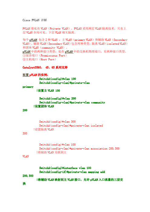
Cisco PVLAN 详解 不错 完整详细

Cisco PVLAN 详解PVLAN即私有VLAN(Private VLAN),PVLAN采用两层VLAN隔离技术,只有上层VLAN全局可见,下层VLAN相互隔离。
每个pVLAN包含2种VLAN :主VLAN(primary VLAN)和辅助VLAN(Secondary VLAN)。
辅助VLAN(Secondary VLAN)包含两种类型:隔离VLAN(isolated VLAN)和团体VLAN(community VLAN)。
pVLAN中的两种接口类型:处在pVLAN中的交换机物理端口,有两种接口类型。
①混杂端口(Promiscuous Port)②主机端口(Host Port)Catalyst3560, 45、65系列支持配置pVLAN的实例:SwitchA(config)#vlan 100SwitchA(config-vlan)#private-vlanprimary!设置主VLAN 100SwitchA(config)#vlan 200SwitchA(config-vlan)#private-vlan community!设置团体VLAN 200SwitchA(config)#vlan 300SwitchA(config-vlan)#private-vlan isolated!设置隔离VLAN 300SwitchA(config)#vlan 100SwitchA(config-vlan)#private-vlan association 200,300!将辅助VLAN关联到主VLANSwitchA(config)#interface vlan 100SwitchA(config-if)#private-vlan mapping add200,300!将辅助VLAN映射到主VLAN接口,允许pVLAN入口流量的三层交换SwitchA(config)# interface fastethernet 0/2SwitchA(config-if)#switchport mode private-vlan hostSwitchA(config-if)#switchport private-vlan host-association 100 200!2号口划入团体VLAN 200SwitchA(config)# interface fastethernet 0/3SwitchA(config-if)#switchport mode private-vlan hostSwitchA(config-if)#switchport private-vlan host-association 100 300!3号口划入隔离VLAN 300SwitchA(config)# interface fastethernet 0/1SwitchA(config-if)#switchport mode private-vlan promiscuousSwitchA(config-if)#switchport private-vlan mapping 100 add200-300!1号口杂合模式关于端口隔离Switch(config)# interface gigabitethernet1/0/2Switch(config-if)# switchport protectedPVLAN通常用于企业内部网,用来防止连接到某些接口或接口组的网络设备之间的相互通信,但却允许与默认网关进行通信。
华为3COM交换机PVLAN配置说明

1. PVLAN的引入3026下面级联了2016,要求2016下的各个端口互相隔离,即给每个端口划分一个VLAN与此同时,由于上层设备(3026)的VLAN数有限,不允许下层设备(2016)将VLAN透传上来,即2016的上行端口要设为access方式。
但是在2016 上一个access端口是不能属于多个VLAN勺,我们如何才能让带有不同VLAN ID的数据报文发送到同一个access端口呢?这时候,我们就需要使用2016的PVLAN功能。
通过使用PVLAN功能,我们就能够实现将2016下的各个端口划在不同的VLAN A,同时又都能通过上行的Access端口发送出去。
目前,华为3Com公司开发的2008/2016/3026都支持PVLAN功能3026在实际应用中有这样一个需求,组网图如上图所示2. PVLAN配置步骤配置PVLAN的步骤如下:1、创建VLAN命令如下:[2016]vlan via n-id2x设置VLAN类型为primary命令如下:[2016-vla n100] isolate-user-vla n en able3、向VLAN中添加端口(无论是primary vlan还是secondary vlan都一样)命令如下:[2016-vla n 10OJport ethernet port-list4、设置primary vian和secondary vian之间的映射关系命令如下:[2016]isolate-user-vla n primary_vla n_num sec on dary sec on dary_vla n」ist3. PVLAN配置举例1、组网需求Quidway S3526以太网交换机通过端口Ethernet 0/7和端口Ethernet 0/8下接两台Quidway S2008以太网交换机。
S2008 A上VLAN5为primary VLAN包含上行端口Ethernet 0/9 和两个secondary VLAN VLAN1 和VLAN2 VLAN1 包含端口Ethernet 0/1, VLAN2 包含端口Ethernet 0/2 ; S2008B 上VLAN6 为primary VLAN 包含上行端口Ethernet 0/9 和两个secondary VLAN: VLAN3 和VLAN4 VLAN3 包含端口Ethernet 0/3, VLAN4 包含端口Ethernet 0/4o从S3526 看,下接的两个S2008 都只有一个VLAN S2008 A 的VLAN5 S2008 B 的VLAN62x 组网图PVLAN配置组网图3、配置步骤下面只列出S2008的配置过程配置S2008 A!酉己置primary vian。
有关PVLAN的知识

PVLAN 简介及配置PVLAN 简介:PVLAN(Primary vlan)是华为公司系列以太网交换机的一个新特性,它的功能是在小区接入中,通过将用户划入不同的VLAN,实现用户之间二层报文的隔离。
PVLAN 采用二层VLAN的结构,在一台以太网交换机上存在Primary vlan和Secondary vlan。
一个Primary vlan和多个Secondary vlan对应,Primary vlan包含所对应的所有Secondary vlaN中包含的端口和上行端口,这样对上层交换机来说,只须识别下层交换机中的Primary vlan,而不必关心Primary vlan中包含的Secondary vlaN,简化了配置,节省了VLAN资源。
用户可以采用PVLAN实现二层报文的隔离,为每个用户分配一个Secondary VLAN,每个vlan中只包含该用户连接的端口和上行端口;如果希望实现用户之间二层报文的互通,可以将用户连接的端口划入同一个Secondary VLAN中。
PVLAN主要配置任务如下:配置Primary vlan配置Secondary VLAN设置Primary VLAN和Secondary VLAN间的映射关系以上任务都是必选的,一旦启用PVLAN就必须配置。
配置Primary VLAN可以使用下面的命令为一个以太网交换机创建一个Primary vlan,并且向此Primary vlan 中添加端口。
请在全局配置模式下进行创建VLAN的配置,在VLAN配置模式下进行设置VLAN类型为Primary vlan及给该VLAN添加端口的配置。
创建VLAN:vlan vlan-id设置VLAN类型为Primary VLAN:pvlan-type primary向Primary VLAN中添加端口:switchport interface-list一台以太网交换机可以有多个Primary vlan,可以为每个Primary vlan指定多个端口。
PVLAN

PVLAN(private VLAN)私有VLAN作用:能够为VLAN内不同端口之间提供隔离的VLAN,能够在一个VLAN之中实现端口之间的隔离。
注意:配置时,VTP必须为透明模式组成:每个PVLAN包括两种VLAN:1、主VLAN2、辅助VLAN 又分为两种:隔离VLAN、联盟VLAN辅助VLAN是属于主VLAN的,一个主VLAN可以包含多个辅助VLAN。
在一个主VLAN中只能有一个隔离VLAN,可以有多个联盟VLAN三种端口类型:host隔离端口---属于隔离VLANhost联盟端口---属于联盟VLANpromiscuous混杂端口---可以和其它端口通信,不属于任何一个子VLAN,通常是连接网关的端口或是连接服务器的端口。
规则:在一个主VLAN中只能有一个隔离VLAN,可以有多个联盟VLAN隔离VLAN中的主机相互间不能访问,也不能和其它子VLAN访问,也不能和外部VLAN 访问,只能与混杂端口访问联盟VLAN中的主机可以相互访问,可以和混杂端口访问,但不能和其它子VLAN访问,也不能和外部VLAN访问1、设置主VLANSW1(config)#vlan 200private-vlan primary2、设置二级子VLANSW1(config)#vlan 201private-vlan isolated 设置为隔离VLANSW1(config)#vlan 202private-vlan community 设置为联盟VLAN3、将子VLAN划入主VLAN中,建立一个联系SW1(config)#vlan 200private-vlan association 201-202SW1(config)#vlan 200private-vlan association add 203 加入一个子VLAN private-vlan association remove 203 移除一个子VLAN4、将端口设定一个模式,并划入相应的VLAN中int e0switchport mode private-vlan host 设置端口的模式,根据子VLAN的类型成为相应的端口switchport private-vlan host-association 200 201-----将端口划入VLAN200中的子VLAN201int e0switchport mode private-vlan promiscuous 设置混杂端口switchport private-vlan mapping 200 201-202 设定混杂端口所能管理的子VLANswitchport private-vlan mapping 200 add/remove 203 增加或移除一个可管理的子VLANshow vlan private-vlan5、将辅助VLAN映射到主VLAN的第3层SVI接口,从而允许PVALN入口流量的第3层交换。
pvlan和super vlan

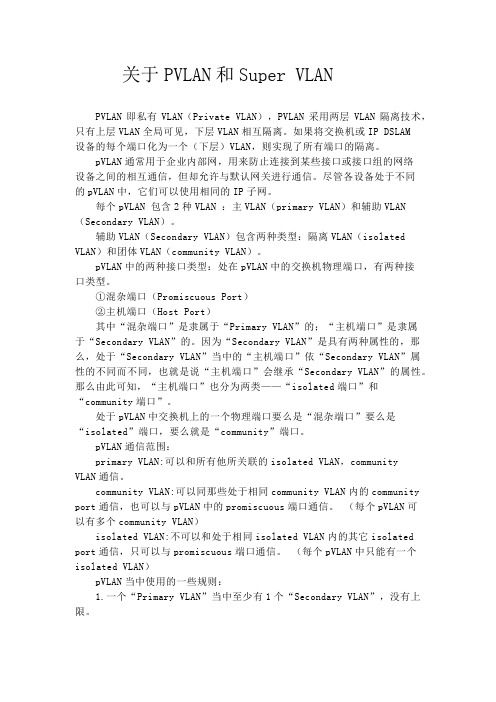
关于PVLAN和Super VLANPVLAN即私有VLAN(Private VLAN),PVLAN采用两层VLAN隔离技术,只有上层VLAN全局可见,下层VLAN相互隔离。
如果将交换机或IP DSLAM设备的每个端口化为一个(下层)VLAN,则实现了所有端口的隔离。
pVLAN通常用于企业内部网,用来防止连接到某些接口或接口组的网络设备之间的相互通信,但却允许与默认网关进行通信。
尽管各设备处于不同的pVLAN中,它们可以使用相同的IP子网。
每个pVLAN 包含2种VLAN :主VLAN(primary VLAN)和辅助VLAN (Secondary VLAN)。
辅助VLAN(Secondary VLAN)包含两种类型:隔离VLAN(isolated VLAN)和团体VLAN(community VLAN)。
pVLAN中的两种接口类型:处在pVLAN中的交换机物理端口,有两种接口类型。
①混杂端口(Promiscuous Port)②主机端口(Host Port)其中“混杂端口”是隶属于“Primary VLAN”的;“主机端口”是隶属于“Secondary VLAN”的。
因为“Secondary VLAN”是具有两种属性的,那么,处于“Secondary VLAN”当中的“主机端口”依“Secondary VLAN”属性的不同而不同,也就是说“主机端口”会继承“Secondary VLAN”的属性。
那么由此可知,“主机端口”也分为两类——“isolated端口”和“community端口”。
处于pVLAN中交换机上的一个物理端口要么是“混杂端口”要么是“isolated”端口,要么就是“community”端口。
pVLAN通信范围:primary VLAN:可以和所有他所关联的isolated VLAN,community VLAN通信。
community VLAN:可以同那些处于相同community VLAN内的community port通信,也可以与pVLAN中的promiscuous端口通信。
PVLAN的结构、工作原理及配置分析

龙源期刊网
PVLAN的结构、工作原理及配置分析
作者:薛媛
来源:《现代电子技术》2014年第01期
摘要: PVLAN是一种高级VLAN技术,用于保证接入层用户的二层隔离,用户只能同
网关进行通信,并通过网关与其他用户实现三层通信。
从PVLAN的结构、工作原理和应用场景及配置等三个方面对PVLAN技术进行了深入的分析,为PVLAN在实际中正确应用奠定了基础。
关键词:专用VLAN;主VLAN;隔离VLAN;团体VLAN
中图分类号: TN915.08⁃34 文献标识码: A 文章编号: 1004⁃373X(2014)
01⁃0080⁃03
0 引言
随着网络的迅速发展,网络用户通信的安全性要求越来越高;传统的解决方法是给每个客户分配一个VLAN和相关的IP子网,通过使用VLAN,每个客户被从第2层隔离开,可以防止任何恶意的行为和Ethernet的信息探听。
然而,这种分配每个客户单一VLAN和IP子网的模型造成了以下局限:交换机固有的VLAN数目的限制;复杂的STP:对于每个VLAN,每
个相关的Spanning Tree的拓扑都需要管理;IP地址的紧缺:IP子网的划分势必造成一些IP地址的浪费;路由的限制:每个子网都需要相应的默认网关的配置。
为了解决以上问题,一种高级VLAN技术——专用VLAN(Private VLAN)应运而生。
1 PVLAN基本结构
Private VLAN是能够为相同VLAN内不同端口提供隔离的VLAN。
PVLAN可以将一个VLAN的二层广播域划分成多个子域,每个子域都由一对VLAN组成:Primary VLAN(主VLAN)和Secondary VLAN(辅助VLAN),如图1所示。
SVLAN,CVLAN,PVLAN VPI VCI概念和区别

交换局端的ADSL Modem产品大多具有多路复用功能(DSLAM:DSL Access Multiplexer)。各条ADSL线路传来的信号在DSLAM中进行复用,通过高速接口向主干网的路由器等设备转发,这种配置可节省路由器的端口,布线也得到简化。目前已有将数条ADSL线路集束成一条10BASE-T的产品和将交换机架上全部数据综合成155 Mbit/s ATM端口的产品。
从业务应用看:ATM-DSLAM应用PVC实现隧道机制、安全机制和带宽承诺机制,QoS的性能也较好,适合开放VPN业务。而IP-DSLAM的PVC由于在局端设备终结,IP在数据安全性及带宽控制方面又有先天的不足,且QoS性能较差,所以更适合访问型的Internet业务。
从用户认证看:ATM-DSLAM的认证是通过将PVC终结在ATM宽带接入服务器(BAS)上实现的。而IP-DSLAM的PVC的映射将VLAN标识符(ID)送给IP-BAS来对用户进行认证(也就是说如果没有VLAN ID送给上层的BAS,就无法对用户进行认证)。因此必须要求IP-DSLAM支持VLAN的数较多,以在PVC和VLAN ID上进行一对一的映射和唯一利用VLAN ID来表示用户。
VPI和VCI是ATM传输的名词,ATM把一条物理电路划分为几个虚拟的逻辑通路,称为VPI;然后在每一个VPI中再划分虚拟的信道(Channel),称为VCI。
一、宽带ADSL和运营商网的连接
1997年6月阿尔卡特、微软等公司联合发表了ADSL系统规范,给出了利用ADSL设备设计ATM网络的基本方法。图中显示出了ATM终端利用ADSL线路建立永久虚电路(PVC)的实例。通常对各个ATM终端独立地设定VPI(虚路径标识符)和VCI(虚通道标识符),ATM终端设定VCI,VPI作为DSLAM识别各ATM终端(ADSL线路)的标志。
AR、CR、BR、SR及LAN的区别

AR、CR、BR、SR及LAN的区别AR接⼊路由器BR汇聚路由器CR核⼼路由器SR业务路由器PE\CE\P是MPLS VPN⾥的概念AR\BR\CR\SR都可以做PE\CE\P设备⼀般CR/BR是不会做PE设备的,只做P设备。
AR作为PE设备。
除⾮⽹络未完全建设开,CR/BR在做P设备时兼做PE设备。
SR为业务路由器,⼀般做PE设备VLAN:⼀个VLAN就是⼀个⼴播域,⽤⼀个标签来表⽰.(802.1q 标准定义,在以太⽹ethernetII/802.3的SA后加⾯增加4字节⽤来给这个以太⽹帧打标签和优先级值)PVLAN:private vlan,VLAN的⼀种应⽤,是完全从实际应⽤⾓度⽽⾔的,⽤以实现⼀个VLAN内的⽤户之间有些能通信,有些不能通信,但这个VLAN⾥的所有⽤户都能通过同⼀个端⼝出去或者访问服务器这样⼀个实际需求包含primary VLAN,isolated VLAN 和communicate VLAN,其中isloate VLAN和communicate VLAN绑定在primary VLAN上,isolated PVLAN内的⽤户之间互相隔离,但可以和primary vlan内的Promiscuous port通信, communicate PVLAN内的⽤户之间可以互相通信,也能与primary vlan内的Promiscuous port通信.SVLAN和CVLAN: Service provider VLAN和customer VLAN,由802.1ad定义, QinQ,在⼀个VLAN⾥再增⼀层标签,成为双标签的VLAN,外层的就是SVLAN,内层的就是CVLAN你提出的最后⼀个问题:"这三者SVLAN、PVLAN、CVLAN之间是否可以配合使⽤"当⼀个交换机启⽤double tagging mode也即802.1q tunneling的时候,⽤户数据包⾃⾝携带VID的就是CVLAN,进⼊交换机后,会被再打上⼀层标签SVLAN,成为⼀个双标签的数据,如果⽤户是ungtagged的数据包,交换机可以打上两层标签,内层打上端⼝的PVID成为CVLAN,外层打上SPVLAN.还可以是直接接把PVID作为SPVLAN,成为单标签数据.交换机处理时可以根据内层标签也可以根据外层标签,交换机不同可以有不同的实现⽅式.SVLAN和CVLAN是孪⽣兄弟,相对的概念,就是配合使⽤的,PVLAN是802.1q的应⽤⽅式,⽽VLAN和SLVAN能共存在,所以这三者完全可以配合使⽤。
pVLAN详解

pVLAN详解pVLAN通常用于企业内部网,用来防止连接到某些接口或接口组的网络设备之间的相互通信,但却允许与默认网关进行通信。
尽管各设备处于不同的pVLAN中,它们可以使用相同的IP子网。
pVLAN 的3种port:isolated,community ,promiscuous。
pVLAN 的3种子VLAN :primary VLAN ,isolated VLAN(second vlan),community VLAN(second vlan)。
pVLAN通信范围:primary VLAN:可以和所有他所关联的isolated VLAN,community VLAN通信. community VLAN:可以同那些处于相同community VLAN内的community port通信,也可以与pVLAN中的promiscuous端口通信。
(每个pVLAN可以有多个community VLAN)isolated VLAN:不可以和处于相同isolated VLAN内的其它isolated port通信,只可以与promisuous端口通信。
(每个pVLAN中只能有一个isolated VLAN)pVLAN限制:pVLAN要求使用VTPv1或VTPv2。
pVLAN必须工作于Transparent模式。
禁止将第3层VLAN接口配置为辅助VLAN。
EtherChannel或SPAN目标端口不支持pVLAN。
配置命令://建立primary VLANvlan 10private-vlan primary//建立isolated VLANvlan 11private-vlan isolated//建立community VLANvlan 12private-vlan community//关联primary VLAN与Second VLANsvlan 10private-vlan association 11,12//配置promiscuousinterface G0/0switchportswitchport mode private-vlan promiscuousswitchport private-vlan mapping 10 11,12注:这里promiscuous port可以属于多个secondary VLAN,但只可以属于一个primary VLAN,就好像普通的access port只能属于一个vlan是一样的。
Pvlan详解

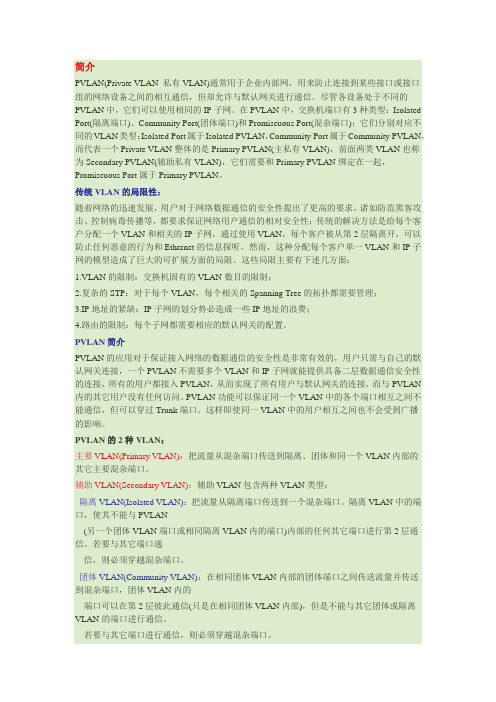
简介PVLAN(Private VLAN 私有VLAN)通常用于企业内部网,用来防止连接到某些接口或接口组的网络设备之间的相互通信,但却允许与默认网关进行通信。
尽管各设备处于不同的PVLAN中,它们可以使用相同的IP子网。
在PVLAN中,交换机端口有3种类型:Isolated Port(隔离端口)、Community Port(团体端口)和Promiscuous Port(混杂端口);它们分别对应不同的VLAN类型:Isolated Port属于Isolated PVLAN,Community Port属于Community PVLAN,而代表一个Private VLAN整体的是Primary PVLAN(主私有VLAN),前面两类VLAN也称为Secondary PVLAN(辅助私有VLAN),它们需要和Primary PVLAN绑定在一起,Promiscuous Port属于Primary PVLAN。
传统VLAN的局限性:随着网络的迅速发展,用户对于网络数据通信的安全性提出了更高的要求,诸如防范黑客攻击、控制病毒传播等,都要求保证网络用户通信的相对安全性;传统的解决方法是给每个客户分配一个VLAN和相关的IP子网,通过使用VLAN,每个客户被从第2层隔离开,可以防止任何恶意的行为和Ethernet的信息探听。
然而,这种分配每个客户单一VLAN和IP子网的模型造成了巨大的可扩展方面的局限。
这些局限主要有下述几方面:1.VLAN的限制:交换机固有的VLAN数目的限制;2.复杂的STP:对于每个VLAN,每个相关的Spanning Tree的拓扑都需要管理;3.IP地址的紧缺:IP子网的划分势必造成一些IP地址的浪费;4.路由的限制:每个子网都需要相应的默认网关的配置。
PVLAN简介PVLAN的应用对于保证接入网络的数据通信的安全性是非常有效的,用户只需与自己的默认网关连接,一个PVLAN不需要多个VLAN和IP子网就能提供具备二层数据通信安全性的连接,所有的用户都接入PVLAN,从而实现了所有用户与默认网关的连接,而与PVLAN 内的其它用户没有任何访问。
PVLAN和supervlan区别

物理的,都是要加入实际的端口才能激活的。
PVLAN采用两层VLAN隔离技术,只有上层vlan全局可见,下层vlan相互隔离。
supervlan又称为vlan聚合,其原理是一个supervlan包含多个subvlan,每个
subvlan是一个广播域,不同subvlan之间二层相互隔离。supervlan可以配置三
层接口,subvlan不能配置三层接口。
二层隔离端口间的三层互通。
supervlan是节省ip地址的。可以让不同vlan的网关使用同一个ip。而这个ip就是
supervlan的ip,这是逻辑上的vlan,它是不需要把商品加到这个vlan里的,下面的不
同的vlan都可以看做是它的子vlan,这些子vlan是物理的,要加端口才能激活
要有一个子vlan是激活的,那么supervlan就是激活的。
当subvlan内的用户需要进行三层通信时,将使用supervlan三层接口的ip地址作为
网关地址,这样多个subvlan共用一个ip网段,从而节省了地址资源。
同时,为了实现不同subvlan间的三层互通及subvlan与其他网络的互通,需要利用
arp代理功能,通过arp代理可以进行arp请求和响应报文的转发与处理,从而实现了
《高级交换与路由技术》习题及答案

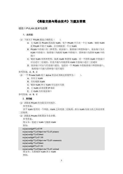
《高级交换与路由技术》习题及答案项目1 PVLAN技术与应用1.选择题(1)下面关于PVLAN描述正确的是()。
A.主VLAN是PVLAN的高级VLAN,每个PVLAN中只有一个主VLAN。
辅助VLAN 是PVLAN中的子VLAN,并且映射到一个主VLANB.PVLAN中的端口有三种类型:混杂端口、隔离端口和团体端口,混杂端口为主VLAN中的端口,隔离端口为隔离VLAN中的端口,团体端口为团体VLAN中的端口C.辅助VLAN有两种类型,隔离VLAN和团体VLAN,同一个团体VLAN中的端口可以进行二层通信,但是不能与其他团体VLAN中的端口进行二层通信D.混杂端口可以与任意端口通信,包括同一个PVLAN中的隔离端口和团体端口,隔离端口只能与团体端口进行通信参考答案:A、B、C(2)一个Private VLAN处于Active状态必须满足的条件为()。
A.具有主VLANB.具有辅助VLANC.辅助VLAN和主VLAN可以进行关联D.主VLAN必须设置IP地址E.主VLAN内有混杂端口参考答案:A、B、C2.简答题(1)请描述PVLAN的功能及应用场合。
参考答案:多个VLAN使用同一个网段、VLAN之间需要二层隔离、部分VLAN内部主机之间也需要二层隔离。
(2)请描述PVLAN的配置命令及步骤。
参考答案:第1步:创建主VLAN与辅助VLAN例如:ruijie(config)#VLAN 99ruijie(config-VLAN)#private-VLAN primaryruijie(config-VLAN)#exitruijie(config)#VLAN 100ruijie(config-VLAN)#private-VLAN communityruijie(config-VLAN)#exitruijie(config)#VLAN 101ruijie(config-VLAN)#private-VLAN isolated第2步:关联辅助VLAN到主VLAN例如:ruijie(config)#VLAN 99ruijie(config-VLAN)#private-VLAN association 100,101第3步:将辅助VLAN映射到主VLAN的三层端口ruijie(config)#interface VLAN 99ruijie(config-if)#ip address 192.168.1.1 255.255.255.0ruijie(config-if)#private-VLAN mapping 100-101第4步:配置主机端口(Host Port)ruijie(config)#interface FastEthernet0/10ruijie(config-if)#switchport mode private-VLAN host第5步:配置混杂端口ruijie(config)#interface FastEthernet 0/1ruijie(config-if)#switchport mode private-VLAN promiscuous(3)请说明PVLAN中各子VLAN中IP地址是如何分配的。
pvlan和DHCP Snnoping的配置

Dhcp动态绑定:(S2126G)入设备限制用户只能通过DHCP获取IP地址,静态配置的IP地址无效Switch(config)#service dhcp //打开DHCP 服务,这里指打开DHCP RelayAgent。
Switch(config)#service dhcp address-bind port //打开DHCP 动态绑定。
Switch(config)#ip helper-address 10.1.1.1 //设置DHCP Server 的IP 地址。
Switch(config)#port-security arp-check //开启ARP报文检查:Switch(config)#interface range fastEthernet 0/10 – 20Switch(config-if-range)#switchport port-security //开启接口的安全功能Private VLAN 配置为了隔绝广播风暴,划了几个vlan,使用pvlan方式划分,1--10口为子vlan501,其中的口可相互通讯,11-20口为vlan502,其中的口相互隔离,20-24为主vlan50的共用出口S5750(config)#vlan 501S5750(config-vlan)#private-vlan communityS5750(config)#vlan 502S5750(config-vlan)#private-vlan isolatedS5750(config)#vlan 50S5750(config-vlan)#private-vlan primaryS5750(config-vlan)#private-vlan association 501-502S5750(config)#interface range gigabitEthernet 0/1 - 10S5750(config-if-range)#switchport mode private-vlan hostS5750(config-if-range)#switchport private-vlan host-association 50 501S5750(config)#interface range gigabitEthernet 0/11 - 20S5750(config-if-range)#switchport mode private-vlan hostS5750(config-if-range)#switchport private-vlan host-association 50 502S5750(config)#interface range gigabitEthernet 0/21 – 24S5750(config-if-range)#switchport mode private-vlan promiscuousS5750(config-if-range)#switchport private-vlan mapping 50 501-502DHCP snooping (s5750)只能从接口1连着的DHCP服务器申请IP,才能正常通信。
二层交换技术介绍

onu
数据(100)
IPTV(200)
语音(300)
VLAN配置举例
该例中要进行4中业务vlan的包括管理业务,数据 业务,语音业务,IPTV业务.其中管理vlan使用 包含上联口29:1,vid为9。数据业务vlan包含上 联口29:2以及所有onu的1号端口,vid为1- 100,IPTV业务包含上联口29:3以及所有onu 的2号端口,vid为200。语音业务包含上联口 29:4以及所有onu的pots口,vid为300。具体 配置步骤如下:
相关协议标准及实现方法
协议讨论的范围与一致性要求 VLAN实现框架 帧标记格式 VLAN桥的操作规则及VLAN桥的管理
协议讨论的范围
802.1Q协议讨论支持VLAN结构的MAC桥的一般实现和操作方法、增强 的MAC服务 增强性内部子层服务E-ISS VLAN桥中提供的帧中继 帧中VLAN控制信息插入、删除、修改等管理规则 自动配置VLAN拓扑信息的需求 遵从该协议标准的设备须满足的要求
一致性要求(一)
兼容802.3协议标准对MAC桥的要求 对帧进行过滤和中继转发 在每个端口上至少支持一种可接收帧类型 在每个支持无标记和优先级标记帧的端口上必须有一个 PVID、能够至少配置一个VLAN、能够通过管理层配置 PVID的值、通过管理层配置静态滤波器的条目 支持从中继帧中插入、去除、修改标签头的功能
VLAN桥的操作规则——入口规则
VID为null VLAN ID FFF VID 入口使能被置位且不在VLAN集合中时拒绝 未被Discard的帧提交发送
网络名词术语解释

AR接入路由器BR汇聚路由器CR核心路由器SR业务路由器PE\CE\P是MPLS VPN里的概念AR\BR\CR\SR都可以做PE\CE\P设备一般CR/BR是不会做PE设备的,只做P设备。
AR作为PE设备。
除非网络未完全建设开,CR/BR在做P设备时兼做PE设备。
SR为业务路由器,一般做PE设备VLAN:一个VLAN就是一个广播域,用一个标签来表示.(802.1q 标准定义,在以太网ethernetII/802.3的SA后加面增加4字节用来给这个以太网帧打标签和优先级值)PVLAN:private vlan,VLAN的一种应用,是完全从实际应用角度而言的,用以实现一个VLAN内的用户之间有些能通信,有些不能通信,但这个VLAN里的所有用户都能通过同一个端口出去或者访问服务器这样一个实际需求包含primary VLAN,isolated VLAN和communicate VLAN,其中isloate VLAN和communicate VLAN 绑定在primary VLAN上,isolated PVLAN内的用户之间互相隔离,但可以和primary vlan内的Promiscuous port通信, communicate PVLAN内的用户之间可以互相通信,也能与primary vlan内的Promiscuous port通信.SVLAN和CVLAN: Service provider VLAN和customer VLAN,由802.1ad定义, QinQ,在一个VLAN里再增一层标签,成为双标签的VLAN,外层的就是SVLAN,内层的就是CVLAN当一个交换机启用double tagging mode也即802.1q tunneling的时候,用户数据包自身携带VID的就是CVLAN,进入交换机后,会被再打上一层标签SVLAN,成为一个双标签的数据,如果用户是ungtagged的数据包,交换机可以打上两层标签,内层打上端口的PVID成为CVLAN,外层打上SPVLAN.还可以是直接接把PVID 作为SPVLAN,成为单标签数据.交换机处理时可以根据内层标签也可以根据外层标签,交换机不同可以有不同的实现方式.SVLAN和CVLAN是孪生兄弟,相对的概念,就是配合使用的,PVLAN是802.1q的应用方式,而VLAN和SLVAN能共存在,所以这三者完全可以配合使用。
PVLAN详解

Jul14Private VLANs Revisited62 CommentsTweetDue to the non-decreasing interest to the post about Private VLANs, I decided to make another one, more detailed – including a diagram and verification techniques.IntroductionTo begin with, recall that VLAN is essentially a broadcast domain. Private VLANs (PVANs) allow splitting the domain into multiple isolated broadcast “subdomains”, introducing sub-VLANs inside a VLAN. As we know, Ethernet VLANs can not communicate directly with each other – they require a L3 device to forward packets between separate broadcast domains. The same restriction applies to PVLANS – since the subdomains are isolated at Level 2, they need to communicate using an upper level (L3/packet forwarding) device – such as router.In reality, different VLANs normally map to different IP subnets. When we split a VLAN using PVLANs, hosts in different PVLANs still belong to the same IP subnet, yet now they need to use a router (L3 device) to talk to each other (for example, by using Local Proxy ARP). In turn, the router may either permit or forbid communications between sub-VLANs using access-lists. Commonly, these configurations arise in “shared” environments, say ISP co-location, where it’s beneficial to put multiple customers into the same IP subnet, yet provide a good level of isolation between them.Private VLANs TerminologyThe following is the reference diagram that we are going to use to illustrate Private VLAN concepts and functionality.For our sample configuration, we take VLAN 1000 and divide it into three PVLANs – sub-VLAN 1012 (R1 and R2), sub-VLAN 1034 (R3 and R4) and sub-VLAN 1055 (router R5 only). Router R6 will be used as layer 3 device, to resolve the layer 3 communication issue. We name VLAN 1000 as “Primary” and c lassify the ports, assigned to this VLAN, based on their types:∙Promiscuous (“P”) port: Usually connects to a router. This port type is allowed to send and receive L2 frames from any other port on the VLAN.∙Isolated (“I”) port: This type of port is only allowed to communicate with “P”-ports – i.e., they are “stub” port. You commonly see these ports connecting to hosts.∙Community (“C”) port: Community ports are allowed to talk to their buddies, sharing the same community (group) and to “P”-ports.In order to implement sub-VLAN behavior, we need to define how packets are forwarded between different types of ports. We group the VLANs in “Primary” and “Secondary”.∙Primary VLAN (VLAN 1000 in our example). This VLAN is used to forward frames downstream from “P”-ports to all other port types (“I” and “C” ports) in the system.Essentially, Primary VLAN embraces all ports in the domain, but only transports framesfrom the router to hosts (from “P” to “I” and “C”).∙Secondary Isolated VLAN: forwards frames from “I” ports to “P” ports. Since Isolated ports do not exchange frames with each other, we can use just ONE isolated VLAN toconnect all I-Port to the P-port.∙Secondary Community VLANs: Transport frames between community ports (C-ports) within to the same group (community) and forward frames upstream to the P-ports of the primary VLAN.How Private VLANs WorkHere are the key aspects of Private VLAN functioning:∙The Primary VLAN delivers frames downstream from the router (promisc port) to all mapped hosts.∙The Isolated VLAN transports frames from the stub hosts upstream to the router∙The Community VLANs allow bi-directional frame exchange withing a single group, in addition to forwarding frames upstream towards “P”-ports.∙Ethernet MAC address learning and forwarding procedure remain the same, as well as broadcast/multicast flooding procedure within boundaries of primary/secondary VLANs.Private VLANs could be trunked. The secondary VLAN numbers are used to tag frames, just as with regular VLANs, and the primary VLAN traffic is trunked as well. However, you need to configure Private VLAN specific settings (bindings, mappings) on every participating swtich, as it’s not possible to use VTPv2 to dissiminate that information . This due to the fact that VTPv2 has no TLVs to carry private VLANs information. VTPv3 was designed to overcome this limitation among others.Configuring Private VLANsWe have primary VLAN 1000, Isolated VLAN 1005 (R5) Community VLAN 1012 (R1, R2) and Community VLAN 1034 (R3, R4).Step 1:First, disable VTP, i.e. enable VTP transparent mode. After disabling VTP, create Primary and Secondary VLANs and bind them into PVLAN domain:SW1:vtp mode transparent!! Creating primary VLAN, which is shared among secondary’s!vlan 1000private-vlan primary!! Community VLAN for R1 and R2: allows a “subVLAN” within a Primary VLAN!vlan 1012private-vlan community!! Community VLAN for R3 and R4!vlan 1034private-vlan community!! Isolated VLAN: Connects all stub hosts to router.! Remember - only one isolated vlan per primary VLAN.! In our case, isolates R5 only.!vlan 1055private-vlan isolated!! Associating the primary with secondary’s!vlan 1000private-vlan association 1012,1034,1055This step is needed is to group PVLANs into a shared domain and establish a formal association (for syntax checking and VLAN type verifications). Repeat the same operations on SW2, since VTP has been disabled.Step 2:Configure host ports and bind them to the respective isolated PVLANs. Note that a host port belongs to different VLANs at the same time: downstream primary and upstream secondary. Also, enable trunking between switches, to allow private VLANs traffic to pass between switches.SW1:!! Community port (links R1 to R2 a nd “P”-ports)!interface FastEthernet0/1description == R1switchport private-vlan host-association 1000 1012switchport mode private-vlan hostspanning-tree portfast!! Community port (links R3 to R4 and “P”-ports)!interface FastEthernet0/3description == R3switchport private-vlan host-association 1000 1034switchport mode private-vlan hostspanning-tree portfast!! Isolated port (uses isolated VLAN to talk to “P”-ports) !interface FastEthernet0/5description == R5switchport private-vlan host-association 1000 1055switchport mode private-vlan hostspanning-tree portfast!! Trunk port!interface FastEthernet 0/13switchport trunk encapsulation dot1qswitchport mode trunkSW2:interface FastEthernet0/2description == R2switchport private-vlan host-association 1000 1012switchport mode private-vlan hostspanning-tree portfast!interface FastEthernet0/4description == R4switchport private-vlan host-association 1000 1034switchport mode private-vlan hostspanning-tree portfast!! Trunk port!interface FastEthernet 0/13switchport trunk encapsulation dot1qswitchport mode trunkNext, Verify the configuration on SW1:Rack1SW1#show vlan id 1012VLAN Name Status Ports---- -------------------------------- --------- ------------------------------- 1012 VLAN1012 active Fa0/13VLAN Type SAID MTU Parent RingNo BridgeNo Stp BrdgMode Trans1 Trans2---- ----- ---------- ----- ------ ------ -------- ---- -------- ------ ------ 1012 enet 101012 1500 - - - - - 0 0Remote SPAN VLAN----------------DisabledPrimary Secondary Type Ports------- --------- ----------------- ------------------------------------------ 1000 1012 community Fa0/1Rack1SW1#show vlan id 1034VLAN Name Status Ports---- -------------------------------- --------- ------------------------------- 1034 VLAN1034 active Fa0/13VLAN Type SAID MTU Parent RingNo BridgeNo Stp BrdgMode Trans1 Trans2---- ----- ---------- ----- ------ ------ -------- ---- -------- ------ ------ 1034 enet 101034 1500 - - - - - 0 0Remote SPAN VLAN----------------DisabledPrimary Secondary Type Ports------- --------- ----------------- ------------------------------------------ 1000 1034 community Fa0/3Rack1SW1#show vlan id 1055VLAN Name Status Ports---- -------------------------------- --------- ------------------------------- 1055 VLAN1055 active Fa0/13VLAN Type SAID MTU Parent RingNo BridgeNo Stp BrdgMode Trans1 Trans2---- ----- ---------- ----- ------ ------ -------- ---- -------- ------ ------ 1055 enet 101055 1500 - - - - - 0 0Remote SPAN VLAN----------------DisabledPrimary Secondary Type Ports------- --------- ----------------- ------------------------------------------ 1000 1055 isolated Fa0/5Rack1SW1#show interfaces fastEthernet 0/13 trunkPort Mode Encapsulation Status Native vlanFa0/13 desirable 802.1q trunking 1Port Vlans allowed on trunkFa0/13 1-4094Port Vlans allowed and active in management domainFa0/13 1,1000,1012,1034,1055Port Vlans in spanning tree forwarding state and not prunedFa0/13 1,1000,1012,1034,1055Verify on SW2:Rack1SW2#show vlan id 1000VLAN Name Status Ports---- -------------------------------- --------- ------------------------------- 1000 VLAN1000 active Fa0/13VLAN Type SAID MTU Parent RingNo BridgeNo Stp BrdgMode Trans1 Trans2---- ----- ---------- ----- ------ ------ -------- ---- -------- ------ ------ 1000 enet 101000 1500 - - - - - 0 0Remote SPAN VLAN----------------DisabledPrimary Secondary Type Ports------- --------- ----------------- ------------------------------------------1000 1012 community Fa0/2, Fa0/61000 1034 community Fa0/4, Fa0/61000 1055 isolated Fa0/6Rack1SW2#show vlan id 1012VLAN Name Status Ports---- -------------------------------- --------- ------------------------------- 1012 VLAN1012 active Fa0/13VLAN Type SAID MTU Parent RingNo BridgeNo Stp BrdgMode Trans1 Trans2---- ----- ---------- ----- ------ ------ -------- ---- -------- ------ ------ 1012 enet 101012 1500 - - - - - 0 0Remote SPAN VLAN----------------DisabledPrimary Secondary Type Ports------- --------- ----------------- ------------------------------------------ 1000 1012 community Fa0/2, Fa0/6Rack1SW2#show vlan id 1034VLAN Name Status Ports---- -------------------------------- --------- ------------------------------- 1034 VLAN1034 active Fa0/13VLAN Type SAID MTU Parent RingNo BridgeNo Stp BrdgMode Trans1 Trans2---- ----- ---------- ----- ------ ------ -------- ---- -------- ------ ------ 1034 enet 101034 1500 - - - - - 0 0Remote SPAN VLAN----------------DisabledPrimary Secondary Type Ports------- --------- ----------------- ------------------------------------------ 1000 1034 community Fa0/4, Fa0/6Rack1SW2#show vlan id 1055VLAN Name Status Ports---- -------------------------------- --------- -------------------------------1055 VLAN1055 active Fa0/13VLAN Type SAID MTU Parent RingNo BridgeNo Stp BrdgMode Trans1 Trans2---- ----- ---------- ----- ------ ------ -------- ---- -------- ------ ------1055 enet 101055 1500 - - - - - 0 0Remote SPAN VLAN----------------DisabledPrimary Secondary Type Ports------- --------- ----------------- ------------------------------------------1000 1055 isolated Fa0/6Rack1SW2#show interface fastEthernet 0/13 trunkPort Mode Encapsulation Status Native vlanFa0/13 desirable 802.1q trunking 1Port Vlans allowed on trunkFa0/13 1-4094Port Vlans allowed and active in management domainFa0/13 1,1000,1012,1034,1055Port Vlans in spanning tree forwarding state and not prunedFa0/13 1,1000,1012,1034,1055Step 3:Create a promiscuous port and configure downstream mappings. Here we add secondary VLANs for which traffic is received by this particular “P”-port. Primary VLAN is used to send traffic downstream to all “C” and “I” ports per their associations.SW2:!! Promiscuous port, mapped to all secondary VLANs!interface FastEthernet0/6description == R6switchport private-vlan mapping 1000 1012,1034,1055switchport mode private-vlan promiscuousspanning-tree portfastVerify the promiscuous port configuration:Rack1SW2#show int fa 0/6 switch | beg privateAdministrative Mode: private-vlan promiscuousOperational Mode: private-vlan promiscuousAdministrative Trunking Encapsulation: negotiateOperational Trunking Encapsulation: nativeNegotiation of Trunking: OffAccess Mode VLAN: 1 (default)Trunking Native Mode VLAN: 1 (default)Administrative Native VLAN tagging: enabledVoice VLAN: noneAdministrative private-vlan host-association: noneAdministrative private-vlan mapping: 1000 (VLAN1000) 1012 (VLAN1012) 1034 (VLAN1034) 1055 (VLAN1055)Administrative private-vlan trunk native VLAN: noneAdministrative private-vlan trunk Native VLAN tagging: enabledAdministrative private-vlan trunk encapsulation: dot1qAdministrative private-vlan trunk normal VLANs: noneAdministrative private-vlan trunk private VLANs: noneOperational private-vlan:1000 (VLAN1000) 1012 (VLAN1012) 1034 (VLAN1034) 1055 (VLAN1055)If you need to configure an SVI on a switch to communicate with private VLAN members, you should add an interface corresponding to Primary VLAN only. Obviously that’s because all secondary VLANs are “subordinates” of primary. After an SVI has been created, you have to map the required secondary VLANs to the SVI (just like with a promiscuous port) in order to make communications possible. You may exclude some mappings from SVI interface, and limit it to communicating only with certain secondary VLANs.SW1:!! SW1 SVI is mapped to all secondary VLANs!interface Vlan 1000ip address 10.0.0.7 255.255.255.0private-vlan mapping 1012,1034,1055SW2:!! SW2 SVI is mapped to 1012/1034 only, so it’s cant communicate with R5!interface Vlan1000ip address 10.0.0.8 255.255.255.0private-vlan mapping 1012,1034Now to verify the configuration, configure R1-R6 in terfaces in subnet “10.0.0.0/24” and ping broadcast addresses.Rack1R1#ping 10.0.0.255 repeat 1Type escape sequence to abort.Sending 1, 100-byte ICMP Echos to 10.0.0.255, timeout is 2 seconds:Reply to request 0 from 10.0.0.7, 4 msReply to request 0 from 10.0.0.2, 4 msReply to request 0 from 10.0.0.6, 4 msReply to request 0 from 10.0.0.8, 4 msRack1R3#ping 10.0.0.255 repeat 1Type escape sequence to abort.Sending 1, 100-byte ICMP Echos to 10.0.0.255, timeout is 2 seconds:Reply to request 0 from 10.0.0.7, 4 msReply to request 0 from 10.0.0.4, 4 msReply to request 0 from 10.0.0.6, 4 msReply to request 0 from 10.0.0.8, 4 msRack1R5#ping 10.0.0.255 repeat 1Type escape sequence to abort.Sending 1, 100-byte ICMP Echos to 10.0.0.255, timeout is 2 seconds:Reply to request 0 from 10.0.0.7, 1 msReply to request 0 from 10.0.0.6, 1 msRack1R6#ping 10.0.0.255 repeat 1Type escape sequence to abort.Sending 1, 100-byte ICMP Echos to 10.0.0.255, timeout is 2 seconds:Reply to request 0 from 10.0.0.1, 4 msReply to request 0 from 10.0.0.7, 4 msReply to request 0 from 10.0.0.2, 4 msReply to request 0 from 10.0.0.5, 4 msReply to request 0 from 10.0.0.3, 4 msReply to request 0 from 10.0.0.4, 4 msReply to request 0 from 10.0.0.8, 4 msLastly, there is another feature, called protected port or “Private VLAN edge”. The feature is pretty basic and is available even on low-end Cisco switches. It allows isolating ports in the same VLAN. Specifically, all ports in a VLAN, marked as protected are prohibited from sending frames to each other (but still allowed to send frames to other (non-protected) ports within the same VLAN). Usually,ports configured as protected are also configured not to receive unknown unicast (frame with destination MAC address not in switch’s MAC table) and multicast frames flooding for added security .Example:interface range FastEthernet 0/1 - 2switchport mode accessswitchport protectedswitchport block unicastswitchport block multicast。
- 1、下载文档前请自行甄别文档内容的完整性,平台不提供额外的编辑、内容补充、找答案等附加服务。
- 2、"仅部分预览"的文档,不可在线预览部分如存在完整性等问题,可反馈申请退款(可完整预览的文档不适用该条件!)。
- 3、如文档侵犯您的权益,请联系客服反馈,我们会尽快为您处理(人工客服工作时间:9:00-18:30)。
pVLAN的配置
pVLAN(Private VLAN,私用VLAN)是能够为相同VLAN内不同端口之间提供隔离的VLAN。
通过隔离相同VLAN之中的网络设备之间的流量,Cisco所提出的pVLAH 能够提高安全性、降低IP子网数目和降低VLAN利用率。
每个PVLAN包括2种VLAN:主VLAN和辅助VLAN
主VLAN:主PVLAN是PVLAN中的高级VLAN.主VLAN由很多个辅助VLAN组成,且辅助VLAN属于主VLAN的相同子网.
辅助VLAN:辅助VLAN是主VLAN的子代,并且映射到一个主VLAN。
每台设备连接到辅助PVLAN
Promiscuous端口PVLAN中的全部设备进行通信.混杂端口只是主VLAN的一部分。
每个混杂端口可以映射到多个辅助VLAN。
混杂端口通常是路由器端口,备分服务器或者VLAN接口.
辅助VLAN 包括如下两种类型:
团体VLAN-如果端口属于团体VLAN,那么它就不仅能够与相同团体VLAN中的其他端口进行
通信,而且还能够与PVLAN的混杂端口进行通信。
隔离VLAN-如果端口属于隔离VLAN,那么它只能与混杂端口进行通信.隔离VLAN 端口不能与相同隔离VLAn中的其他端口进行通信.
PVLAN、
在配置PVALN的时候,因为只有VTP透明模式支持PVLAN,所以必须首先将交换机配置为VTP透明模式.
步骤1:在开始配置PVLAN之前,首先将交换机VTP模式为透明模式.
AS1(config-vlan)#vtp mode transparent
步骤2:在交换机AS1,创建主Pvlan 100,团体Pvlan 101 和隔离Pvlan 102。
此外,建立辅助Pvlan和主pvlan 的关联.
AS1(config-vlan)#vlan 100
AS1(config-vlan)#private-vlan primary //将VLAN100配置为主pVLAN
AS1(config-vlan)#private-vlan association 101-102 //建立辅助pVLAN与主pVLAN的关联
AS1(config-vlan)#vlan 101
AS1(config-vlan)#private-vlan community //将VLAN101配置为团体pVLAN AS1(config-vlan)#vlan 102
AS1(config-vlan)#private-vlan isolated //将VLAN102配置为隔离pVLAN
步骤3:将VLAN100配置为主PVLAN,并且将其映射到辅助PVLAN101 和102. AS1(config)#interface vlan 100
AS1(config-if)#no shut
AS1(config-if)#private-vlan mapping 101,102 //将辅助pVLAN映射到第3层VLAN接口以实现路由功能
步骤4:在交换机AS1上,将主机A的接口配置为Pvlan 101的成员,将主机B 的接口配置为Pvlan 102的成员.
AS1(config)#interface fastEtherne t 2/3
AS1(config-if)#description Host_A
AS1(config-if)#swithport
AS1(config-if)#swithport mode private-vlan host //将端口配置为主机端口
AS1(config-if)#swithport private-vlan host-association 100 101 //建立第2层接口与pVLAN的关联
AS1(config-if)#no shutdown
AS1(config-if)#interface fastethernet 2/4
AS1(config-if)#description Host_B
AS1(config-if)#swithport
AS1(config-if)#swithport mode private-vlan host //将端口配置为主机端口
AS1(config-if)#swithport private-vlan host-association 100 102 //建立第2层接口与pVLAN的关联
AS1(config-if)#no shutdown
步骤5:验证私用VLAN配置,并且确认主机A不能成功ping通主机B。
