ad9832中文资料
全国电子设计大赛---必练模块
模块训练
1.稳压电源具有多路不同电压输出、可调输出(常用的正负5V、正负
2.5-18V可调输出)。
输出功率较大、可调线性度较好、电压纹波峰峰值小于10mV ……
2.参照模电书的甲乙类功放电路做一个分立元件音频功放电路(前级可用运放),输出功
率达到5W以上,有音量调节功能,频率响应范围在100Hz-2000Hz或更宽,输出噪声电压有效值V0N≤5mV……(掌握三极管、运放的工作原理)
3.用单片机和数码管或液晶制作电子钟(包括温度),可以单片机延时、定时器计时,也可以用时钟芯片(掌握数码管、液晶的工作原理)
4.4X4矩阵键盘,或者用编码器做键盘。
在此基础上可用专门的键盘芯片(如74LS138、CH452、7279,掌握键盘的工作原理)
5.简易电压表,用AD芯片采集电压信号并显示,精度在5%以内(至少能测正负5V内)(学习AD的使用)
6.简易信号发生器,用DA产生正弦波、三角波、锯齿波、方波信号,要求频率可调。
(学习DA的使用)
7.写液晶菜单,滚屏,翻页……(320240、19264、12864)
8.高通、低通、带通、带阻滤波器(学习滤波器)
9.单片机内部资源的使用,中断、定时器、串行通信……
10.多机通信、微机与PC机通信
11.程控增益放大、有效值检测(AD603/AD637)
(1)输入正弦电压信号范围为:10mV PP~1V PP;
(2)输入信号频率范围为:100Hz~50KHz;
(3)可通过按键方式手动改变增益,使输出电压信号范围为1V PP~1.5V PP(峰峰值V PP),且无明显失真,显示电压值。
12.DDS信号发生器(AD9832、AD9833、AD9854)。
AD9833中文资料精编版

高精度可编程波形发生器AD9833中文资料1.AD9833概述AD9833是ADI公司生产的一款低功耗,可编程波形发生器,能够产生正弦波、三角波、方波输出。
波形发生器广泛应用于各种测量、激励和时域响应领域,AD9833无需外接元件,输出频率和相位都可通过软件编程,易于调节,频率寄存器是28位的,主频时钟为25MHz时,精度为0.1Hz,主频时钟为1MHz时,精度可以达到0.004Hz。
可以通过3个串行接口将数据写入AD9833,这3个串口的最高工作频率可以达到40MHz,易于与DSP和各种主流微控制器兼容。
AD9833的工作电压范围为2.3V-5.5V。
AD9833还具有休眠功能,可使没被使用的部分休眠,减少该部分的电流损耗,例如,若利用AD9833输出作为时钟源,就可以让DAC休眠,以减小功耗,该电路采用10引脚MSOP型表面贴片封装,体积很小。
AD9833的主要特点如下:●频率和相位可数字编程;●工作电压为3V时,功耗仅为20mW;●输出频率范围为0MHz-12.5MHz;●频率寄存器为28位(在25MHz的参考时钟下,精度为0.1Hz);●可选择正弦波、三角波、方波输出;●无需外界元件;●3线SPI接口;●温度范围为-40℃-+105℃。
2 AD9833的结构及功能2.1 电路结构AD9833是一块完全集成的DDS(Direct Digital Frequency Synthesis)电路,仅需要1个外部参考时钟、1个低精度电阻器和一个解耦电容器就能产生高达12.5MHz的正弦波。
除了产生射频信号外,该电路还广泛应外于各种调制解调方案。
这些方案全都用在数字领域,采用DSP技术能够把复杂的调制解调算法简化,而且很精确。
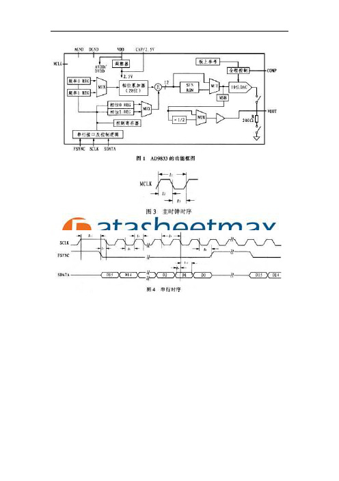
AD9833的内部电路主要有数控振荡器(NCO)、频率和相位调节器、Sine ROM、数模转换器(DAC)、电压调整器,其功能框图如图1所示。
AD933的核心是28位的相位累加器,它由加法器和相位寄存器组成,每来1个时钟,相位寄存器以步长增加,相位寄存器的输出与相位控制字相加后输入到正弦查询表地址中。
DAC0832中文资料

D/A转换器DAC0832DAC0830/DAC08328位μP兼容、双缓冲D/A转换器总述DAC0832是采用CMOS工艺制成的单片直流输出型8位数/模转换器。
旨在直接与8080,8048,8085,Z80及其他通用的微型处理器进行相接。
存储的硅铬R-2R 电阻梯形网络将参考电流分开,并为电路提供合适的温度处理特性(全范围最大线性温度误差的0.05%)。
电路利用CMOS电流开关和控制逻辑来取得最少的电能损耗和最小的输出泄露电流误差。
特殊的电路也能提供TTL逻辑输入电压的水平兼容。
双缓冲可以使这些D/A转换器在获取下一个数位字时输出相应一个数位字的电压。
这就使得任何一个D/A转换器均可进行同步更新。
D/A转换器0830系列是8位的可兼容微型处理器的D/A转换器的集合。
特征⏹双缓冲,单缓冲,或流通数字数据输入⏹可容易地与12位1230系列D/A转换器进行互换且插脚兼容⏹可直接与所有流通的微型处理器相接⏹线性指定为零,且只能进行全面调整——不是最佳直线拟合⏹在±10V全参考4象限倍增中工作⏹可用于电压转换模式⏹逻辑输入满足TTL电压水平说明(1.4V逻辑门限值)⏹需要时,可运行“STAND ALONE”(没有μP)⏹存在于20插脚小型或者模塑芯片运载包中性能及规格描述⏹电流设置时间:1μs⏹分辨率:8位⏹线性度:8,9或者10位(保证温度)⏹低功耗:20mW⏹单电源提供:直流5-15V典型应用图1典型应用连接连接图图2双行和小外形封装图3 封装图绝对最大额定参数(注解1,2)如果需要军事/航空特定设备,请联系国家半导体销售中心/分支机构咨询其有效性及性能。
电源电压(VCC) 17V直流电压输出电压 VCC-GND输入VREF ±12V储存温度范围 -65 ° C至+150 ° C封装耗散当TA= 25 ℃(注3 ) 500Mw直流电压的应用IOUT1或IOUT2 (注4 ) -100 mV到VCC公共服务电子化Susceptability (注4 ) 800V焊接温度(焊接, 10秒。
直接数字频率合成芯片AD9832原理及其典型应用设计

《测控技术》2004年第23卷第12期·68·文章编号:1000–8829(2004)12–0068–03直接数字频率合成芯片AD9832原理及其典型应用设计DDS AD9832 and It’s Typical Application(同济大学交通信息工程系,上海 200331)沈拓,董德存摘要:直接数字式频率合成技术可以提供快速的信号建立时间,纯净的信号频谱,方便地产生各种波形,实现各种调制方式,在通信与电子系统中广泛应用。
笔者介绍了直接数字频率合成芯片AD9832的组成结构、转换原理和典型应用电路,分析了与80C51的接口时序,并给出了C驱动源代码。
关键词:直接数字频率合成;AD9832;开关电容滤波器;80C51中图分类号:TN74文献标识码:BAbstract:Direct digital synthesis can offer high converting speed,pure singal spectrum,and generate many types of wave-form,realize some modulations. It is widely used in communica-tion and electronic systems because of these special advantages. The composition,operational principle and typical application circuit of AD9832 are introduced. AD9832 to 80C51 interface,timing and C driver source code are discussed.Key words:direct digital synthesis ; AD9832 ; switched capacitor filter ; 80C51直接数字式频率合成(DDS,direct digital synthesis)是近年出现的新一代频率合成方法,采用全数字化VLSI技术设计,与传统的直接频率合成及PLL锁相环频率合成相比,信号建立时间快,一般在几ns到几µs;频率分辨率高;频率转换时相位保持连续;容易实现QAM、FSK、PSK和GMSK等各种调制方式[1]。
高精度可编程波形发生器中文资料

高精度可编程波形发生器中文资料1.AD9833概述AD9833是ADI公司生产的一款低功耗;可编程波形发生器;能够产生正弦波、三角波、方波输出..波形发生器广泛应用于各种测量、激励和时域响应领域;AD9833无需外接元件;输出频率和相位都可通过软件编程;易于调节;频率寄存器是28位的;主频时钟为25MHz时;精度为0.1Hz;主频时钟为1MHz时;精度可以达到0.004Hz..可以通过3个串行接口将数据写入AD9833;这3个串口的最高工作频率可以达到40MHz;易于与DSP和各种主流微控制器兼容..AD9833的工作电压范围为2.3V-5.5V..AD9833还具有休眠功能;可使没被使用的部分休眠;减少该部分的电流损耗;例如;若利用AD9833输出作为时钟源;就可以让DAC休眠;以减小功耗;该电路采用10引脚MSOP型表面贴片封装;体积很小..AD9833的主要特点如下:●频率和相位可数字编程;●工作电压为3V时;功耗仅为20mW;●输出频率范围为0MHz-12.5MHz;●频率寄存器为28位在25MHz的参考时钟下;精度为0.1Hz;●可选择正弦波、三角波、方波输出;●无需外界元件;●3线SPI接口;●温度范围为-40℃-+105℃..2 AD9833的结构及功能2.1 电路结构AD9833是一块完全集成的DDSDirect Digital Frequency Synthesis电路;仅需要1个外部参考时钟、1个低精度电阻器和一个解耦电容器就能产生高达12.5MHz的正弦波..除了产生射频信号外;该电路还广泛应外于各种调制解调方案..这些方案全都用在数字领域;采用DSP技术能够把复杂的调制解调算法简化;而且很精确..AD9833的内部电路主要有数控振荡器NCO、频率和相位调节器、Sine ROM、数模转换器DAC、电压调整器;其功能框图如图1所示..AD933的核心是28位的相位累加器;它由加法器和相位寄存器组成;每来1个时钟;相位寄存器以步长增加;相位寄存器的输出与相位控制字相加后输入到正弦查询表地址中..正弦查询表包含1个周期正弦波的数字幅度信息;每个地址对应正弦波中0°-360°范围内的1个相位点..查询表把输入的地址相位信息映射成正弦波幅度的数字量信号;去DAC输出模拟量;相位寄存器每经过228/M个MCLK时钟后回到初始状态;相应地正弦查询表经过一个循环回到初始位置;这样就输出了一个正弦波..输出正弦波频率为:fOUT=MfMCLK/228 1其中;M为频率控制字;由外部编程给定;其范围为0≤M≤228-1..VDD引脚为AD9833的模拟部分和数字部分供电;供电电压为2.3V-5.5V..AD9833内部数字电路工作电压为2.5V;其板上的电压调节器可以从VDD产生2.5V稳定电压;注意:若VDD小于等于2.7V;引脚CAP/2.5V应直接连接至VDD..2.2 功能描述AD9833有3根串行接口线;与SPI、QSPI、MI-CROWIRE和DSP接口标准兼容;在串口时钟SCLK的作用下;数据是以16位的方式加载到设备上;时序图如图3所示;FSYNC引脚是使能引脚;电平触发方式;低电平有效..进行串行数据传输时;FSYNC引脚必须置低;要注意FSYNC有效到SCLK下降沿的建立时间t7的最小值..FSYNC置低后;在16个SCLK的下降沿数据被送到AD9833的输入移位寄存器;在第16个SCLK的下降沿FSYNC可以被置高;但要注意在SCLK下降沿到FSYNC上升沿的数据保持时间ts的最小和最大值..当然;也可以在FSYNC 为低电平的时候;连续加载多个16位数据;仅在最后一个数据的第16个SCLK的下降沿的时将FSYNC置高;最后要注意的是;写数据时SCLK时钟为高低电平脉冲;但是;在FSYNC刚开始变为低时;即将开始写数据时;SCLK必须为高电平注意t11这个参数..当AD9833初始化时;为了避免DAC产生虚假输出;RESET必须置为1RESET不会复位频率、相位和控制寄存器;直到配置完毕;需要输出时才将RESET置为0;RESET为0后的8-9个MCLK时钟周期可在DAC的输出端观察到波形..AD9833写入数据到输出端得到响应;中间有一定的响应时间;每次给频率或相位寄存器加载新的数据;都会有7-8个MCLK时钟周期的延时之后;输出端的波形才会产生改变;有1个MCLK时钟周期的不确定性;因为数据加载到目的寄存器时;MCLK的上升沿位置不确定..3 AD9833的引脚功能及时序AD9833的引脚排列如图2所示;各个引脚的功能描述见表1..AD9833的时序特性如图3、图4和表2所示..4 AD9833的内部寄存器功能AD9833内部有5个可编程寄存器;其中包括3个16位控制寄存器;2个28位频率寄存器和2个12位相位寄存器..4.1 控制寄存器AD9833中的16位控制寄存器供用户设置所需的功能..除模式选择位外;其他所有控制位均在内部时钟MCLK的下沿被AD9833读取并动作;表3给出控制寄存器各位的功能;要更改AD9833控制寄存器的内容;D15和D14位必须均为0..4.2 频率寄存器和相位寄存器AD9833包含2个频率寄存器和2个相位寄存器;其模拟输出为fMCLK/228×FREQEG 2其中:FREQEG为所选频率寄存器中的频率字;该信号会被移相:2π/4096×PHASEREC 3其中;PHASEREC为所选相位寄存器中的相位字..频率和相位寄存器的操作如表4所示..5 应用设计AD9833可应用在L15型飞机控制盒配套的检测盒中;利用AD9833产生频率可调的正弦波;以模拟机轮速度传感器的速度信号;从而对控制盒的刹车防滑通道能否正常的刹车防滑进行检测..5.1 AD9833应用电路检测盒设计以TI公司的TMS320LF2407A型DSP作为核心控制器;应用中需要2路速度信号;因此需要检测盒给出2路可独立调节的频率;图5示出TMS320LF2407A与AD9833的硬件连接..外接有源晶体振荡器的输出送给2个AD9833作为主频时钟;DSP的SPI口采用主动工作方式;即用SPISIMO口发送数据;为了与AD9833的时序相配合;DSP的接口时钟SPICLK信号方式选择有延时的下降沿;IOPC3和IOPC5作为电路选通信号;IOPC3为低电平时U2被选通;此时对U1写数据无效;同理;IOPC53为低电平时U1被选通;此时对U2写数据无效..5.2 软件程序图6示出了AD9833的软件流程..无论是写控制寄存器、频率寄存器还是相位寄存器、在写数据之前都需要把选通信号置为有效状态;这样写入的数据才会有效;否则无效..在DSP发送完1个数据字后将产生SPI中断请求;本设计中未使用中断方式;而且通过查询中断标志来跳出;并虚读DSP的接收缓冲器清除中断标志..。
ad9832 stm32源代码

SPI_InitStructure.SPI_CPOL = SPI_CPOL_Low;
//
SPI_InitStructure.SPI_CPHA = SPI_CPHA_2Edge;
SPI_InitStructure.SPI_NSS = SPI_NSS_Soft;
SPI_InitStructure.SPI_BaudRatePrescaler = SPI_BaudRatePrescaler_8;
SPI_InitStructure.SPI_FirstBit = SPI_FirstBit_MSB;
SPI_InitStructure.SPI_CRCPolynomial = 0;
SPI_Init(SPI1, &SPI_InitStructure);
SPI_Cmd(SPI1, ENABLE);
//
GPIO_SetBits(GPIOA,GPIO_Pin_2);
SendData(0x5000); }
//void SPI1_AD9832_Config(uint32_t FREQ_REG) //{ // SendData(AD_RESET); // SendData(AD_Fre0_LLSBs|(FREQ_REG&0x00ff)); // SendData(AD_Fre0_HLSBs|(FREQ_REG>>8&0x00ff)); // SendData(AD_Fre0_LMSBs|(FREQ_REG>>16&0x00ff)); // SendData(AD_Fre0_HMSBs|(FREQ_REG>>24&0x00ff)); // SendData(AD_PHA0_LSBs); // SendData(AD_PHA0_MSBs); // SendData(AD_RegGroup);//使用频率寄存器 0、相位寄存器 0; // SendData(AD_Set_FSelect); // SendData(AD_Start); //} void delay(void) {
AN983中文资料
AN983B/AN983BLPCI/miniPCI-to-Ethernet LAN ControllerDATASHEETRev. 1.8MAY. 2003Information in this document is provided in connection with ADMtek products. ADMtek may make changes to specifications and product descriptions at any time, without notice. Designers must not rely on the absence or characteristics of any features or instructions marked "reserved" or "undefined." ADMtek reserves these for future definition and shall have no responsibility whatsoever for conflicts or incompatibilities arising from future changes to them.The products may contain design defects or errors known as errata, which may cause the product to deviate from published specifications. Current characterized errata are available on request. To obtain latest documents, please contact your localADMtek sales office or your distributor or visit ADMtek’s website at *Third-party brands and names are the property of their respective owners.CONTENTSDatasheet Revision History (2)1. GENERAL DESCRIPTIONS (9)2. SYSTEM BLOCK DIAGRAM (10)3. FEATURES (11)I NDUSTRY STANDARD (11)FIFO (11)I/F (11)PCIEEPROM/B OOT ROM I/F (11)MAC/P HYSICAL (12)D ISPLAY (12)LEDM ISCELLANEOUS (12)4. BLOCK DIAGRAM (13)5. PIN ASSIGNMENT DIAGRAM (14)6. PIN DESCRIPTION (15)7. REGISTERS AND DESCRIPTORS DESCRIPTION (19)7.1 AN983B configuration registers (20)7.1.1. AN983B configuration registers list (20)7.1.2. AN983B configuration registers table (21)7.1.3 AN983B configuration registers descriptions (22)CR0 (offset = 00h), LID - Loaded Identification number of Device and Vendor (22)CR1 (offset = 04h), CSC - Configuration command and status (22)CR2 (offset = 08h), CC - Class Code and Revision Number (23)CR3 (offset = 0ch), LT - Latency Timer (23)CR4 (offset = 10h), IOBA - I/O Base Address (24)CR5 (offset = 14h), MBA - Memory Base Address (24)CR11 (offset = 2ch), SID - Subsystem ID (24)CR12 (offset = 30h), BRBA - Boot ROM Base Address (24)CR13 (offset = 34h), CP - Capabilities Pointer (25)CR15 (offset = 3ch), CI - Configuration Interrupt (25)CR16 (offset = 40h), DS - Driver Space for special purpose (25)CR32 (offset = 80h), SIG - Signature of AN983B (25)CR48 (offset = c0h), PMR0, Power Management Register0 (26)CR49 (offset = c4h), PMR1, Power Management Register 1 (26)7.2. PCI Control/Status registers (28)7.2.1. PCI Control/Status registers list (28)7.2.2. Control/Status register description (29)CSR0 (offset = 00h), PAR - PCI Access Register (29)CSR1 (offset = 08h), TDR - Transmit demand register (30)CSR2 (offset = 10h), RDR - Receive demand register (30)CSR3 (offset = 18h), RDB - Receive descriptor base address (30)CSR5 (offset = 28h), SR - Status register (30)CSR6 (offset = 30h), NAR - Network access register (32)CSR7 (offset = 38h), IER - Interrupt Enable Register (34)CSR8 (offset = 40h), LPC - Lost packet counter (35)CSR9 (offset = 48h), SPR - Serial port register (35)CSR11 (offset = 58h), TMR -General-purpose Timer (36)CSR13 (offset = 68h), WCSR –Wake-up Control/Status Register (36)CSR14 (offset = 70h), WPDR –Wake-up Pattern Data Register (37)CSR15 (offset = 78h), WTMR - Watchdog timer (38)CSR16 (offset = 80h), ACSR5 - Assistant CSR5 (Status register 2) (39)CSR17 (offset = 84h), ACSR7- Assistant CSR7 (Interrupt enable register 2).40 CSR18 (offset = 88h), CR - Command Register, bit31 to bit16 (40)CSR19 (offset = 8ch) - PCIC, PCI bus performance counter (42)CSR20 (offset = 90h) - PMCSR, Power Management Command and Status..42 CSR21 (offset = 94h) - WTDP, The current working transmit descriptor pointer (43)CSR22 (offset = 98h) - WRDP, The current working receive descriptor pointer (43)CSR23 (offset = 9ch) - TXBR, transmit burst count / time-out (43)CSR24 (offset = a0h) - FROM, Flash ROM (also the boot ROM) port (44)CSR25 (offset = a4h) - PAR0, physical address register 0 (44)CSR26 (offset = a8h) - PAR1, physical address register 1 (44)CSR27 (offset = ach) - MAR0, multicast address register 0 (45)CSR28 (offset = b0h) - MAR1, multicast address register 1 (45)Operation Mode Register (Memory base offset 0FCh) (46)7.3. PHY Registers (ACCESSED by csr9 MDI/MMC/MDO/MDC) (47)7.3.1. Transceiver registers Descriptions (47)7.4. Descriptors and Buffer Management (51)7.4.1 Receive descriptor (52)7.4.1.1 Receive Descriptor Table (52)7.4.1.2 Receive Descriptor Descriptions (52)RDES0 (52)RDES1 (53)RDES2 (53)RDES3 (53)7.4.2. Transmit Descriptor (53)7.4.2.1. Transmit Descriptor Table (53)7.4.2.2. Transmit Descriptor Descriptions (54)TDES0 (54)TDES1 (54)TDES2 (55)TDES3 (55)8. FUNCTIONAL DESCRIPTIONS (56)8.1 Initialization Flow (56)8.2 Network Packet Buffer Management (57)8.2.1 Descriptor Structure Types (57)8.2.2 The point of descriptor management (59)8.3 Transmit Scheme and Transmit Early Interrupt (61)8.3.1 Transmit flow (61)8.3.2 Transmit pre-fetch data flow (61)8.3.3 Transmit early interrupt Scheme (62)8.4 Receive scheme and Receive early interrupt scheme (63)8.5 Network Operation (65)8.5.1 MAC Operation (65)8.5.2 Transceiver Operation (66)8.5.3 Flow Control in Full Duplex Application (69)8.6 LED Display Operation (72)8.6.1 First mode - 3 LED displays for (72)8.6.2 Second mode – 4 LED displays for (72)8.7 Reset Operation (72)8.7.1 Reset whole chip (72)8.7.2 Reset Transceiver only (72)8.8 Wake on LAN Function (73)8.8.1 The Magic Packet format (73)8.8.2 The Wake on LAN operation (73)8.9 ACPI Power Management Function (73)8.9.1 Power States (74)Power State (74)9. GENERAL EEPROM FORMAT DESCRIPTION (76)Connection Type Definition (76)10. ELECTRICAL SPECIFICATIONS AND TIMINGS (78)10.1 Absolute Maximum Ratings (78)10.2 DC Specifications (78)General DC Specifications (78)PCI Interface DC Specifications (78)Flash/EEPROM Interface DC Specifications (78)10.3 AC Specifications (79)PCI Signaling AC Specifications for 3.3V (79)10.4 Timing Specifications (79)PCI Clock Specifications (79)PCI Timings (80)Flash Interface Timings (81)EEPROM Interface Timings (AC/AD) (83)11. PACKAGE (87)Dimensions for 128 –pin PQFP Package(AN983B) (87)Dimensions for 128 –pin LQFP Package(AN983BL) (88)12. LAYOUT GUIDE (REV.1.0B) (89)Layout Guide Revision History: (89)12.1 placement (89)12.2 trace routing (89)12.3 Vcc and GND (90)FIGURE INDEXFig - 1 System diagram of the AN983B (10)Fig - 2 Block diagram of the AN983B (13)Fig - 3 Pin assignment (14)Fig - 4 Initializatin flow (56)Fig - 5 Ring structure of frame buffer (57)Fig - 6 Chain structure of frame buffer (58)Fig - 7 Transmit pointers for descriptor management (59)Fig - 8 Receive pointers for descriptor management (60)Fig - 9 Transmit flow (61)Fig - 10 Transmit data flow of pre-fetch data (62)Fig - 11 Transmit normal interrupt and early interrupt comparison (62)Fig - 12 Receive data flow (without early interrupt and with early interrupt) (63)Fig - 13 Detailed receive early interrupt flow (64)Fig - 14 MAC Control Frame Format (70)Fig - 15 PAUSE operation receive state diagram (71)Fig - 16 PCI Clock Waveform (79)Fig - 17 PCI Timings (81)Fig - 18 Flash write timings (82)Fig - 19 Flash read timings (83)Fig - 20 Serial EEPROM timing (84)Fig - 21 Transmit signal timing relationships at theMII (887)Fig - 22 Receive signal timing relations at the MII (87)Fig - 23 MDIO sourced by MAC (87)Fig - 24 MDIO sourced by PHY (87)Fig - 25 Package outline for the AN983B/AN983BL (87)1. GENERAL DESCRIPTIONSThe AN983B is a high performance PCI Fast Ethernet controller with integrated physical layer interface for 10BASE-T and 100BASE-TX application.The AN983B was designed with advanced CMOS technology to provide glueless 32-bit bus master interface for PCI, boot ROM interface, CSMA/CD protocol for Fast Ethernet, as well as the physical media interface for 100BASE-TX of IEEE802.3u and 10BASE-T of IEEE802.3. The auto-negotiation function is also supported for speed and duplex detection.The AN983B can be programmed as MAC-only controller. In this mode, it provides the standard MII interface to link to an external PHY. With this mode, it can be connected to the HomePNA PHY to support the HomePNA networking solution or Homeplug Phy(Power-line solution) to support Homeplug networking solution..The AN983B provides both half-duplex and full-duplex operation, as well as support forfull-duplex flow control.It provides long FIFO buffers for transmission and receiving, and early interrupt mechanism to enhance performance.The AN983B also supports ACPI and PCI compliant power management function and Magic Packet wake-up event.3. FEATURESINDUSTRY STANDARDIEEE802.3u 100BASE-TX and IEEE802.3 10BASE-T compliantSupport for IEEE802.3x flow controlIEEE802.3u Auto-Negotiation support for 10BASE-T and 100BASE-TXPCI Specification 2.2 compliantACPI and PCI power management Ver.1.1 compliantSupport PC99 wake on LANFIFOProvides two independent long FIFOs with 2k bytes each for transmission and receiving Pre-fetch up to two transmit packets to minimize inter frame gap (IFG) to 0.96usRetransmits collided packet without reload from host memory within 64 bytes.Automatically retransmits FIFO under-run packet with maximum drain threshold until 3 times retry failure and that will not influence the registers and transmit threshold of next packetPCI I/FProvides 32-bit PCI bus master data transferSupports PCI clock with frequency from 0Hz to 33MHzSupports network operation with PCI system clock from 20MHz to 33MHzProvides performance meter, PCI bus master latency timer, for tuning the threshold to enhance the performanceProvides burst transmit packet interrupt and transmit/receive early interrupt to reduce host CPU utilizationSupports memory-read, memory-read-line, memory-read-multiple, memory-write, memory-write-and-invalidate command while being bus masterSupports big or little endian byte orderingEEPROM/BOOT ROM I/FProvides write-able Flash ROM and EPROM as boot ROM with size up to 128kBProvides PCI to access boot ROM by byte, word, or double wordRe-writes Flash boot ROM through I/O port by programming registerProvides serial interface for read/write 93C46/66 EEPROMAutomatically loads device ID, vendor ID, subsystem ID, subsystem vendor ID, Maximum-Latency, and Minimum-Grand from the 64 byte contents of 93C46/66 after PCI reset de-asserted in PCI environment.MAC/PHYSICALIntegrates the whole Physical layer functions of 100BASE-TX and 10BASE-TProvides Full -duplex operation on both 100Mbps and 10Mbps modesProvides Auto-negotiation (NWAY) function of full/half duplex operation for both 10 and 100 MbpsProvides transmit wave-shaper, receive filters, and adaptive equalizerProvides MLT-3 transceiver with DC restoration for Base-line wander compensationProvides MAC and Transceiver (TXCVR) loop-back modes for diagnosticBuilds in Stream Cipher Scrambler/ De-scrambler and 4B/5B encoder/decoderSupports external transmit transformer with turn ratio 1:1Supports external receive transformer with turn ratio 1:1LED DISPLAY3 LEDs displays scheme provided:100Mbps(on) or Speed 10(off)Link (keeps on when link ok) or Activity (will be blinking with 10Hz whenreceiving or transmitting but not collision)FD (keeps on when in Full duplex mode) or Collision (will be blinking with 20Hzwhen colliding)4 LEDs displayed scheme provided:100Mbps and Link (keep on when link and 100Mpbs)10Mbps and Link (keep on when link and 10Mpbs)Activity (will be blinking with 10Hz when receiving or transmitting but notcollision)FD (keeps on when in Full duplex mode) or Collision (will be blinking with 20Hzwhen colliding)MISCELLANEOUSProvides 128-pin QFP/LQFP packages for PCI/mini-PCI interfaces3.3V power supply with 5V/3.3V I/O tolerance7. REGISTERS AND DESCRIPTORS DESCRIPTIONThere are three kinds of registers designed for AN983B. They are AN983B configuration registers, PCI control/status registers, and Transceiver control/status registers.The AN983B configuration registers are used to initialize and configure the AN983B for identifying and querying the AN983B.The PCI control/status registers are used to communicate between host and AN983B. Host can initialize, control, and read the status of the AN983B through the mapped I/O or memory address space.Regarding the registers of transceiver portion of AN983B, it includes 7 basic registers which are defined according to the clause 22 “Reconciliation Sub-layer and Media Independent Interface” and clause 28 “Physical Layer link signaling for 10 Mb/s and 100 Mb/s Auto-Negotiation on twisted pair” of IEEE802.3u standard. The AN983B also provides receive and transmit descriptors for packet buffering and management. These descriptors are described in the following section。
IC资料-中文AD9833寄存器
~寄存器的频率和相位在AD9833包含两个频率寄存器和2个相位寄存器。
如表三所示表3:频率/相位寄存器在AD9833的模拟输出是fMCLK/228 x FREQREG其中FREQREG是频率选择寄存器的值装入。
该信号将逐步转移登记由2π/4096x PHASEREG在PHASEREG选择阶段是值载英寸的流程图在图8显示了AD9833的例程以书面形式向登记册的频率和相位写入一个频率登记:当写入频率寄存器,位的D15和D14上给予注册地址的频率。
表四。
频率寄存器位如果用户希望改变频率登记的全部内容的,连续两次写入到同一个地址后,必须进行广泛的频率寄存器为28位。
第一次写将包含14个最低有效位,而第二写将包含14个MSB。
此操作模式中,控制位B28座(D13号)应设置为“1”。
写一个例子,一个28位是列于表五表5。
00FC00到FREQ0 复位SDATA Input 结果输入字0010 0000 0000 0000 控制字写入(D15,D14= 00),B28(D13)= 1,HLB(D12的)= x0100 0000 0000 0000 FREQ0写(D15,D14= 01),14个最低有效位= 0000在一些应用中,用户不需要改变频率登记所有28位的。
粗调,只有14个MSB是改变,而与微调,只有14个LSB的改变。
通过设置控制位B28座(D13号)为“0”,28位频率寄存器操作两个最低有效位,14位寄存器,一个包含14个MSB和其他载有14。
这意味着,频率最高位的14个字的最低有效位可以改变的14个独立的,反之亦然。
位HLB值(D12的)在确定了其中14个控制寄存器位被改变。
这方面的例子是表六表七所示。
表六。
写3FFF的14位最低有效位FREQ1复位表七。
写00FF的14个FREQ0的最高有效位写入一期注册时写入一个阶段登记,钻头的D15和D14上都设置为11。
D13号位寄存器确定哪一阶段被加载表八。
AD9832 AD9835编程示例

0x5800—选择FREQ1寄存器。 • 即,将0x5写入命令位C3:C0。 • 将1写入位D11,以选择FREQ1寄存器(见图5)。 FSELECT位复位至0,可返回3 kHz FREQ0输出。
0x5800—选择FREQ0寄存器。
09651-004 09651-005
1
3 4
2
CH2 500mV CH2 5V
命令序列说明 请参考AD9832或AD9835数据手册中的寄存器表。
0xD000—复位AD9832
RESET位DB12置1。这样做可将内部寄存器复位至0,对应于 满量程的模拟输出(见图2)。Ch1为复位的杂散输出。Ch2为 FSYNC,Ch3为SDATA, Ch4为SCLK。注意,数据在SCLK的
AN-1108
09651-003
Rev. 0 | Page 3 of 4
AN-1108
0x9000—使用命令位1:0 将C15至C14的SELSRC置1。 • 将SELSRC置1—FSELECT由数据位控制。迟延增加两个
MCLK周期。 0xC000—频率寄存器1,L LSB数据。 • 退出复位模式。从FREQ0寄存器输出的一个3 kHz信号,
AN09651sc -0-5/11(0)
Rev. 0 | Page 4 of 4
PHASE ACCUMULATOR
(32 BIT)
12
SIN
ROM
10-BIT DAC
COMP IOUT
SYNC
PHASE0 REG PHASE1 REG PHASE2 REG PHASE3 REG
16-BIT DATA REGISTER
MUX
8 MSBs
8 LSBs DEFER REGISTER
DDS芯片AD9832的原理及应用
DDS芯片AD9832的原理及应用2006.05.07 湖南大学电气与信息工程学院江玉蓉周有庆吴桂清来自:国外电子元器件摘要:AD9832是AD公司生产的直接数字频率合成器。
它体积小、重量轻、操作方便,同时具有极高的频率辩率。
文章介绍了直接数字频率合成器(DDS)AD9832的原理,分析了AAD9832的内部结构、引脚功能以及在高频测试仪中的应用。
关键词:直接数字频率合成器 DDS AD9832 高频测试仪直接数字频率合成是一种新的频率合成技术和信号产生方法。
直接数字频率合成器(DDS)具有超高速的频率转换时间,极高的频率分辨率和较低的相位噪声,在频率改变与调频时,DDS器件能够保持相位的连续,因此很容易实现频率、相位和幅度调制。
此外,该器件还具有可编程控制的突出优点。
因此,直接数字频率合成器得到了越来越广泛的应用,成为当今电子系统及设备中频率源的首选器件。
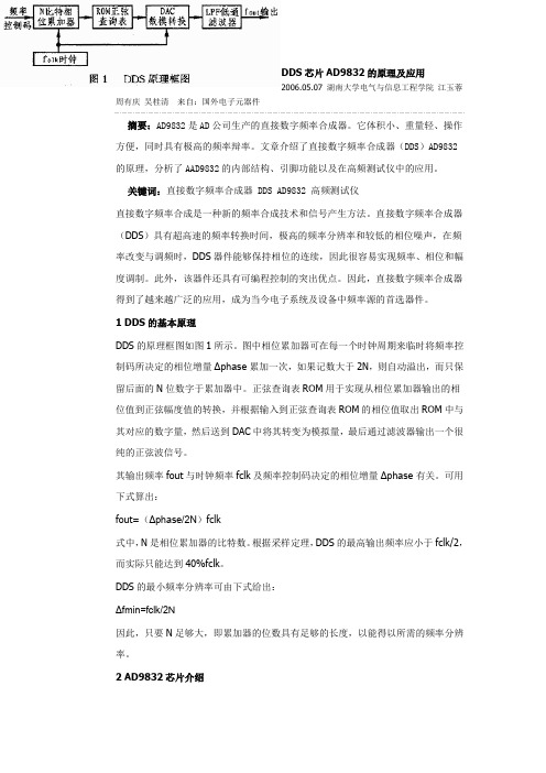
1 DDS的基本原理DDS的原理框图如图1所示。
图中相位累加器可在每一个时钟周期来临时将频率控制码所决定的相位增量Δphase累加一次,如果记数大于2N,则自动溢出,而只保留后面的N位数字于累加器中。
正弦查询表ROM用于实现从相位累加器输出的相位值到正弦幅度值的转换,并根据输入到正弦查询表ROM的相位值取出ROM中与其对应的数字量,然后送到DAC中将其转变为模拟量,最后通过滤波器输出一个很纯的正弦波信号。
其输出频率fout与时钟频率fclk及频率控制码决定的相位增量Δphase有关。
可用下式算出:fout=(Δphase/2N)fclk式中,N是相位累加器的比特数。
根据采样定理,DDS的最高输出频率应小于fclk/2,而实际只能达到40%fclk。
DDS的最小频率分辨率可由下式给出:Δfmin=fclk/2N因此,只要N足够大,即累加器的位数具有足够的长度,以能得以所需的频率分辨率。
2 AD9832芯片介绍2.1 AD9832的内部结构AD9832是AD公司生产的一款完整的DDS芯片,它的最高时钟频率可达25MHz。
AD9832BRUZ资料

REFOUT
REFIN
FS ADJUST COMP
AVDD 10nF
ON-BOARD REFERENCE
FULL-SCALE CONTROL
12
SIN ROM
10-BIT DAC
IOUT 300Ω 50pF
AD9832
Figure 1. Test Circuit with Which Specifications Are Tested –2–
Test Conditions/Comments MCLK Period MCLK High Duration MCLK Low Duration SCLK Period SCLK High Duration SCLK Low Duration FSYNC to SCLK Falling Edge Setup Time FSYNC to SCLK Hold Time Data Setup Time Data Hold Time FSELECT, PSEL0, PSEL1 Setup Time Before MCLK Rising Edge FSELECT, PSEL0, PSEL1 Setup Time After MCLK Rising Edge
CMOS Complete DDS AD9832
The AD9832 is a numerically controlled oscillator employing a phase accumulator, a sine look-up table and a 10-bit D/A converter integrated on a single CMOS chip. Modulation capabilities are provided for phase modulation and frequency modulation. Clock rates up to 25 MHz are supported. Frequency accuracy can be controlled to one part in 4 billion. Modulation is effected by loading registers through the serial interface. A power-down bit allows the user to power down the AD9832 when it is not in use, the power consumption being reduced to 5 mW (5 V) or 3 mW (3 V). The part is available in a 16-lead TSSOP package.
AD9832中文

AN-621APPLICATION NOTE One Technology Way • P.O. Box 9106 • Norwood, MA 02062-9106 • Tel: 781/329-4700 • Fax: 781/326-8703 • Programming the AD9832/AD9835By Colm SlatteryINTRODUCTIONThis application note details how to program 5 MHz on the output of the AD9832/AD9835 parts. The frequency register, defer register, and command sequence are explained in detail.THE FREQUENCY REGISTERThe AD9832 contains a 32-bit frequency register. The register is shown below and is broken up into four bytes. Since the AD9832 accepts only eight bits of data in any one command, in order to fully program the 32-bit register the user must input four commands, each delivering only eight bits of data.For addressing purposes, the 32-bit register is broken up as follows: The 16 MSBs are defined as having eight higher bits (H) and eight lower bits (L). Similarly, the 16 LSBs have the same addressing scheme, eight higher (H) bits and eight lower (L) bits.MSB LSB THE FREQUENCY WORDThe frequency word is the 32-bit word which the user inputs into the frequency register. This determines the output frequency and is based on the ratio of the required output frequency to the reference clock frequency. In the example below, the reference clock is 25 MHz. The re-quired output needs to be 5 MHz, so the frequency word is calculated as:(5/25) (0xFFFFFFFF) = 0x33333333THE DEFER REGISTERThe defer register (16 bits wide) acts as a buffer reg-ister to the last register written to. The defer register is written to in two writes. The first eight bits will be held (deferred) in the register until the next eight bits are written in. When all 16 bits have been written into the defer register, the frequency register will be updated. The defer register always points to the last address that was written to.DEFER REGISTERSince the defer register has stored the last 16 bits writ-ten to it and is still pointing to the frequency register previously addressed, it is possible to update either the lower eight bits or the upper eight bits of that frequency register with one write. T his is called a direct write and is actually the last part of a normal write sequence.Note that if users want to write to any other register, they will have to do a full write sequence as shown above.REV. 0REV. 0E 03543–0–2/03(0)P R I N T E D I N U .S .A .–2–© 2003 Analog Devices, Inc. All rights reserved. T rademarks and registered trademarks are the property of their respective companies.ENTIRE COMMAND SEQUENCE FOR 5 MHz PROGRAM 0xF800 Binary (1111 1000 0000 0000)0x3333 Binary (0011 0011 0011 0011)0x2233 Binary (0010 0010 0011 0011)0x3133 Binary (0011 0001 0011 0011)0x2033 Binary (0010 0000 0011 0011)0xC000 Binary (1100 0000 0000 0000)COMMAND SEQUENCE EXPLAINEDFor the purpose of this explanation, the 16-bit SPI word will be addressed as follows: D15, D14, D13, ..., D2, D1, D00xF800 Binary (1111 1000 0000 0000)D15, D14 = 1,1. T his means that bits D13, D12, and D11 are active. In this case:D13 = 1, SLEEP bit. T his puts the part into sleep mode.D12 = 1, RESET bit. T his sets the part into reset, i.e., output of the DAC will be midscale.D11 = 1, CLR bit. When CLR = 1, SYNC and SELSRC are set to 1. This sets control of choosing which register is selected to external pins, not through software. CLR will automatically reset to 0.D10...D0 = 0. (These are Don’t Care bits, X.) The part is now ready to be programmed. 0x3333 Binary (0011 0011 0011 0011)Command broken down as follows:0011 /* Write eight frequency bits to defer register */0011 /* Write to Frequency 0 Reg, H MSBs */0011 0011 /* Eight bits of data to write */ 0x2233 Binary (0010 0010 0011 0011)0010 /* Write eight frequency bits to defer register */0010 /* Write to Frequency 0 Reg, L MSBs */0011 0011 /* Eight bits of data to write */16 bits are now loaded to the upper 16 bits of Frequency Register 0.0x3133 Binary (0011 0001 0011 0011)0011 /* Write eight frequency bits to defer register */0001 /* Write to Frequency 0 Reg, H LSBs */0011 0011/* Eight bits of data to write */0x2033 Binary (0010 0000 0011 0011)0010 /* Write eight frequency bits to defer register */0000 /* Write to Frequency 0 Reg, L LSBs */0011 0011 /* Eight bits of data to write */16 bits are now loaded to the lower 16 bits of Frequency Register 0.0xC000 Binary (1100 0000 0000 0000)D15, D14 = 1,1. T his means that bits D13, D12, and D11 are active. In this case: D13 = 0, SLEEP bit. T akes the part out of sleep mode.D12 = 0, RESET bit. T akes the part out of reset mode.D11 = 0, CLR bit.D10...D0 = 0 (Don’t Care bits for this command.)5 MHz will now appear on the output pin. T he FSELECT pin must be pulled to GND to choose Frequency Reg 0.。
AD9822资料

元器件交易网
AD9822–SPECIFICATIONS
ANALOG SPECIFICATIONS Gain = 1, unless otherwise noted.)
Parameter MAXIMUM CONVERSION RATE 3-Channel Mode with CDS 1-Channel Mode with CDS ACCURACY (Entire Signal Path) ADC Resolution Integral Nonlinearity (INL) INL @ 6 MHz Differential Nonlinearity (DNL) DNL @ 6 MHz No Missing Codes No Missing Codes @ 6 MHz Offset Error Gain Error ANALOG INPUTS Input Signal Range1 Allowable Reset Transient1 Input Limits2 Input Capacitance Input Bias Current AMPLIFIERS PGA Gain at Minimum PGA Gain at Maximum PGA Gain Resolution2 PGA Gain Monotonicity Programmable Offset at Minimum Programmable Offset at Maximum Programmable Offset Resolution Programmable Offset Monotonicity NOISE AND CROSSTALK Total Output Noise @ PGA Minimum Total Output Noise @ PGA Maximum Channel-Channel Crosstalk @ 6 MHz POWER SUPPLY REJECTION AVDD = +5 V ± 0.25 V DIFFERENTIAL VREF (@ 25°C) CAPT–CAPB (2 V ADC Full-Scale Range) TEMPERATURE RANGE Operating Storage POWER SUPPLIES AVDD DRVDD OPERATING CURRENT AVDD DRVDD Power-Down Mode Current POWER DISSIPATION 3-Channel Mode 3-Channel Mode @ 6 MHz 1-Channel Mode 1-Channel Mode @ 6 MHz 0.94 0 –65 4.75 3.0 5.0 5.0 73 4 150 385 335 300 250 450 410 Min 15 12.5 14 –17.0/+3.5 –10.5/+1.5 –0.65/+0.75 –0.6/+0.65 14 –19 +3.5 2.0 1.0 AVSS – 0.3 10 10 1 5.7 64 Guaranteed –350 +350 512 Guaranteed 1.5 6.0 <1 0.063 1.0 0.9 1.06 +70 +150 5.25 5.25 AVDD + 0.3
W9832AASA资料

32MB (4M x 64) SDRAM SO-DIMM MODULEFeatures•JEDEC standard 144 pins, small-outline, dual in-line memory module (SODIMM)•Utilizes 100 MHz SDRAM components•Unbuffered SO-DIMM•Auto Refresh and Self Refresh•CAS latency: 2 and 3•Burst Length: 1, 2, 4, 8 and full page•4k refresh cycles / 64ms•Interface: LVTTL•Serial Presence Detect with EEPROM•Single 3.3V±0.3V power supply•PCB: height (1,062 mil) single sided componentPart NumberModule Part Number Speed Grade Self-Refresh CurrentW9832AASA-10PC66 CL=2, 38mAW9832AASA10L PC66 CL=2, 3 1.8mAGeneral DescriptionThe Winbond W9832AASA is a 4M x 64 Synchronous Dynamic RAM memory module. This module consists of four pieces of W986416AH (4M x 16 bit) SDRAMs in 54-pin TSOP-II 400mil package, and a 2K EEPROM in 8-pin SOP package on a 144-pin 6-layer PCB. A 0.1 uF decoupling capacitor is used for each SDRAM.The W9832AASA is a Samll Out-line Dual In-line Memory Module for mounitng into 72-pin dual readout zigzag edge connector sockets. It is designed to operate in 3.3V, low-power memory systems.32MB (4M x 64) SDRAM SO-DIMM MODULEPin AssignmentPin Front Pin Back Pin Front Pin Back Pin Front Pin Back 1V SS 2V SS 51DQ1452DQ4695DQ2196DQ533DQ04DQ3253DQ1554DQ4797DQ2298DQ545DQ16DQ3355V SS 56V SS 99DQ23100DQ557DQ28DQ3457NC 58NC 101V DD 102V DD 9DQ310DQ3559NC60NC103A6104A711V DD 12V DD 105A8106BA013DQ414DQ36107V SS 108V SS 15DQ516DQ37Voltage Key109A9110BA117DQ618DQ3861CLK062CKE0111A10/AP112A1119DQ720DQ3963V DD 64V DD 113V DD 114V DD 21V SS 22V SS 65RAS#66CAS#115DQM2116DQM623DQM024DQM467WE#68*CKE1117DQM3118DQM725DQM126DQM569CS0#70A12119V SS 120V SS 27V DD 28V DD 71*CS1#72*A13121DQ24122DQ5629A030A373NC 74CLK1123DQ25124DQ5731A132A475V SS 76V SS 125DQ26126DQ5833A234A577NC 78NC 127DQ27128DQ5935V SS 36V SS 79NC 80NC 129V DD 130V DD 37DQ838DQ4081V DD 82V DD 131DQ28132DQ6039DQ940DQ4183DQ1684DQ48133DQ29134DQ6141DQ1042DQ4285DQ1786DQ49135DQ30136DQ6243DQ1144DQ4387DQ1888DQ50137DQ31138DQ6345V DD 46V DD 89DQ1990DQ51139V SS 140V SS 47DQ1248DQ4491V SS 92V SS 141**SDA 142**SCL 49DQ1350DQ4593DQ2094DQ52143V DD144V DD* These pins are not used in this module.** These pins should be NC in systems which do not support SPD.32MB (4M x 64) SDRAM SO-DIMM MODULEPin DescriptionPin NameFunction DescriptionCLKn Clock Inputs System clock used to sample inputs on the rising edge of clock.CSn#Chip select Disable or enable the command decoder. When command decoder is disabled, new command is ignored and previous operation continues.CKEn Clock Enable CKE controls the clock activation and deactivation. When CKE is low,Power Down mode, Suspend mode, or Self-Refresh mode is entered.A0~A11AddressMultiplexed pins for row and column address.Row address: A0~A11. Column address: A0~A7.BA0~BA1Bank Select Address Selects bank to be activated during row address latch time.Selects bank for read/write during column address latch time.RAS#Row Address Strobe Command input. When sampled at the rising edge of the clock, RAS#,CAS# and WE# define the operation to be executed.CAS#Column Address Strobe Referred to RAS#WE#Write Enable Referred to RAS#DQM0~7Input/Output Mask The output buffer is placed at Hi-Z when DQM is sampled high in read cycle. In write cycle, sampling DQM high will block the write data.DQ0~63Data Input/Output Multiplexed pins for data output and inputV DD Power (+3.3 V)Power for input buffers and logic circuit inside SDRAM.V SS Ground Ground for input buffers and logic circuit inside SDRAM.SCL Serial Clock Clock for serial presence detection SDA Serial Data I/O Data line for serial presence detection NCNo ConnectionNo connection32MB (4M x 64) SDRAM SO-DIMM MODULEBLOCK DIAGRAMS0DQM0DQ (7:0)DQM1DQ (15:8)DQM2DQ(23:16)DQM3DQ(31:24)CKE0RAS CAS WE SDRAM U1, 2, 3, 4SDRAM U1, 2, 3, 4SDAV DDV SSSDRAM U1, 2, 3, 4SDRAM U1, 2, 3, 4One 0.1uF per SDRAM deviceSERIAL PDSDRAM U1, 2, 3, 4SDRAM U1, 2, 3, 4CLK010RSDRAM U1, 2, 3, 4BA(1:0)SDRAM U1, 2, 3, 4A(11:0)SDRAM U1, 2, 3, 432MB (4M x 64) SDRAM SO-DIMM MODULEABSOLUTE MAXIMUM RATINGSSYMBOL ITEM RATING UNIT NOTESV IN, V OUT Input, column Output Voltage-0.3~V CC+0.3VV DD Power Supply Voltage-0.3~4.6VT OPR Operating Temperature0~70°CT STG Storage Temperature-55~125°CP D Power Dissipation9WI OUT Short Circuit Output Current50mANote: Operation exceeds “ABSOLUTE MAXIMUM RATING” may cause permanent damage to the devices. RECOMMENDED DC OPERATING CONDITIONS ( Ta = 0 to 70°C ) SYMBOL PARAMETER MIN TYP MAX UNIT NOTESV DD Power Supply Voltage 3.0 3.3 3.6VV IH Input High Voltage 2.0-V CC+0.3VV IL Input Low Voltage-0.3-0.8VNote: V IH(max) = V DD+1.2V for pulse width < 5nsV IL(min) = V SS-1.2V for pulse width < 5nsAll Voltages are referenced to V SSCAPACITANCE (VCC=3.3V, Af = 1MHz, Ta=25°C)PIN SYMBOL MIN MAX UNIT Address(A0~A11, BA0~BA1)Cadd-16pf RAS#, CAS#, WE#Ccmd-16pf CKE C CKE-16pfCLK0C CLE-24pfCS0#C CS-16pf DQM0~DQM7C DQM-4pfDQ0~DQ63C IO-5pf32MB (4M x 64) SDRAM SO-DIMM MODULEDC CHARACTERISTICS(VCC = 3.3V ± 0.3V, Ta=0°~70°C)-1010LSYMBOLITEMSMINMAXMINMAXUNITNOTESI CC1OPERATING CURRENT t CK=min, t RC =minActive Precharge command cycling without Burst operation 1 bank operation 440440mA 1I CC2CKE=V IH200200I CC2P STANDBY CURRENT t CK =min, CS#=V IHV IH /L=V IH (min)/V IL (max)Bank: inactive state CKE=V IL (Power Down mode)1212mA1I CC2S CKE=V IH2020I CC2PS STANDBY CURRENT CLK=V IL , CS#=V IHV IH/L =V IH (min)/V IL (max)BANK: inactive stateCKE=V IL (Power Down mode)88mAI CC3CKE=V IH 280280mA 1I CC3P No OPERATING CURRENT T CK =min0, CS#=V IH (min)BANK: active state (4banks)CKE=V IL (Power Down mode)3232mA I CC4BURST OPERATING CURRENTT CK =min Read/Write command cycling 760760mA 1, 2I CC5AUTO REFRESH CURRENTT CK =min Auto Refresh command cycling 520520mA 1I CC6SELF REFRESH CURRENT Self Refresh mode CKE=0.2V81.8mANote: 1. These parameters depend on the cycle rate and listed values are measured at a cycle rate with the minimum valuesof t CK and t RC .2. These parameters depend on the output loading conditions. Specified values are obtained with output open.32MB (4M x 64) SDRAM SO-DIMM MODULEAC CHARACTERISTICS AND OPERATING CONDITION( Vcc=3.3V±0.3V, Ta=0° to 70°C )- 1010LSYMBOL PARAMETERMIN MAX MIN MAX UNIT t RC Ref/Active to Ref/Active Command Period9090t rAS Active to precharge Command Period6010000060100000ns t RCD Active to Read/Write Command Delay Time3030t CCD Read/Write(a) to Read/Write(b)CommandPeriod11cyclet RP Precharge to Active(b) Command Period3030t RRD Active(a) to Active(b) Command Period2020Write Recovery Time CL*=2151000151000 t WRCL*=3101000101000 CLK Cycle Time CL*=21515 t CKCL*=31010 t CH CLK High Level33t CL CLK Low Level33Access Time from CLK CL*=299 t ACCL*=388ns t OH Output Data Hold Time33t HZ**Output Data High Impedance Time310310t LZ Output Data Low Impedance Time00t SB Power Down Mode Entry Time010010t T Transition Time of CLK (Rise and Fall)0.5100.510t DS Data-in-Set-up Time33t DH Data-in Hold Time11t AS Address Set-up Time33t AH Address Hold Time11t CKS CKE Set-up Time33t CKH CKE Hold Time11t CMS Command Set-up Time33t CMH Command Hold Time11t REF Refresh Time6464ms t RSC Mode register Set Cycle Time2020ns Note: *CL= CAS Latency** t HZ defines the time at which the outputs achieve the open circuit condition and is not referenced to output level.Refer to the individual component32MB (4M x 64) SDRAM SO-DIMM MODULEAC TESTING CONDITIONSOutput Timing Measurement Reference Level 1.4V/1.4VOutput LoadSee diagram B Below Input Signal Levels2.4V/0.4V Transition Time (Rise and Fall) of Input Signal2ns Input Reference Level1.4V50 ohms1.4 VAC TEST LOAD (B)output AC TEST LOAD (A)output3.3V 50pFNote: Transition times are measured between V IH and V IL32MB (4M x 64) SDRAM SO-DIMM MODULEOperation ModeFully synchronous operations are performed to latch the commands at the positive edges of CLK. Table 1 shows the truth table for the operation commands.Table 1: Truth Table ( note (1), (2))COMMAND Device state CKEn-1CKEn DQM BA0,BA1A10A11,A9-0___CS___RAS___CAS___WEBank Active Idle H X X V V V L L H H Bank Precharge Any H X X V L X L L H L Precharge All Any H X X X H X L L H L Write Active (3)H X X V L V L H L L Write withAutoprechargeActive (3)H X X V H V L H L L Read Active (3)H X X V L V L H L H Read withAutoprechargeActive (3)H X X V H V L H L H Mode Register Set Idle H X X V V V L L L L No – Operation Any H X X X X X L H H H Burst Stop Active (4)H X X X X X L H H L Device Deselect Any H X X X X X H X X X Auto – Refresh Idle H H X X X X L L L H Self - Refresh Entry Idle H L X X X X L L L HSelf Refresh Exitidle(S.R.)LLHHXXXXXXXXHLXHXHXXClock suspend ModeEntryActive H L X X X X X X X XPower Down Mode EntryIdleActive (5)HHLLXXXXXXXXHLXHXHXXClock Suspend ModeExitActive L H X X X X X X X XPower Down Mode ExitAny(power down)LLHHXXXXXXXXHLXHXHXXData write/OutputEnableActive H X L X X X X X X X Data Write/OutputDisableActive H X H X X X X X X X Notes: (1) V= Valid X= Don't care L= Low Level H= High Level(2) CKEn signal is input level when commands are provided.(3) These are state of bank designated by BA0, BA1 signals.(4) Device state is full page burst operation.(5) Power Down Mode can not be entered in the burst cycle. When this command asserts in the burst cycle, devicestate is clock suspend mode32MB (4M x 64) SDRAM SO-DIMM MODULESerial Presence Detect EEPROMThe Serial Presence Detect (SPD) function is implemented using a 2,408-bit EEPROM component. This nonvolatile storage device contains data for identifying the module type and various SDRAM organization and timing parameters. System read operations to the EEPROM device occur using the DIMM SCL(clock) and SDA (data) signals, together with SA(2:0) which provide the EEPROM Device Address.SPD EEPROM DC OPERATING CONDITIONS(Vcc=3.3V±0.3V)PARAMETER/CONDITION SYMBOL MIN MAX UNIT NOTES Supply Voltage V CC 3.0 3.6VInput High (Logic 1) Voltage, all inputs V IH V CC×.7V CC+ .5VInput Low (Logic 0) Voltage, all inputs V IL-0.3V CC×.3VOUTPUT LOW VOTAGE, lout=3 mA V OL0.4V I OL=3mA INPUT LEAKGE CURRENT, Vin=GND to V cc I LI1uAOUTPUT LEAKAGE CURRENT, V OUT=GND to V cc I LO1uASTANDBY CURRENTI SB10uASCL=SDA Vcc -0.3V, All other inputs=GND or 3.3V +10%POWER SUPPLY CURRENTI CC1mASCL clock frequency =100KHzSPD AC OPERATING CONDITIONS(Vcc=3.3V±0.3V)AC CHRARCTERICSPARAMETER SYMBOL MIN MAX UNIT NOTES SCL clock frequency f SCL100KHzNoise Suppression Time Constant at SCL,SDA Inputs t I100nsSCL Low to SDA Data Out Valid t AA0.3 3.5usTime the bus must be free before a new transition can start t BUF 4.7usStart Condition Hold Time t HD:STA 4.0usClock Low Period t LOW 4.7usClock High Period t HIGH 4.0usStart Condition Setup Time t SU:STA 4.7usData in Hold Time t HD:DAT0usData in Setup Time t SU:DAT250nsSDA and SCL Rise time t R1usSDA and SCL Fall Time t F300nsStop Condition Setup Time t SU:STO 4.7usData Out Hold Time t DH300nsWrite Cycle Time t WR15msNote: The write cycle time (t WR) is the time from a valid stop condition of a write sequence to the end of the internal erase/program cycle. During the write cycle the EEPROM bus interface circuits are disabled, SDA is allowed to remain high the bus level pull-up resistor, and the device does not respond to its slave address.32MB (4M x 64) SDRAM SO-DIMM MODULECONTENTS OF EEPROMFUNCTION SUPPORTEDHEX VALUE BYTE NUMBERFUNCTION DESCRIBED-10/10L -10/10L 0Defines # bytes written into serial memory at module manufacturer128 bytes80h 1Total # bytes of SPD memory device256 bytes (2K- bit)08h 2Fundamental memory type (FPM, EDO, SDRAM..)SDRAM 04h 3# Row Addresses on this assembly 120Ch 4# Column Addresses on this assembly 808h 5# Module Rows on this assembly 1 row 01h 6Data Width of this assembly…64 bits 40h 7Data Width continuation-00h 8Voltage interface standard of this assembly LVTTL 01h 9SDRAM Cycle time @CAS latency of 310ns A0h 10SDRAM Access time form clock @CAS latency of 38ns 80h 11DIMM Configuration type (Non-parity, Parity ECC)Non parity00h 12Refresh Rate/Type15.625 us, support self refresh80h 13SDRAM width, Primary DRAM X1610h 14Error Checking SDRAM data widthNone00h 15Minimum Clock Delay, Back Random Column AddressesTCCD=1 CLK01h 16Burst Lengths supported1, 2, 4, 8 & full page8Fh 17#Bank on Each SDRAM device 4 banks 04h 18CAS# Latencies Supported 2 & 306h 19CS# Latency 0 CLK 01h 20Write Latency0 CLK01h 21SDRAM Module Attributes Non-buffered Non –registered &redundant addressing00h 22SDRAM Device Attributes: General+/-10% voltage tolerance, BurstRead, Single bit Write,precharge all, auto precharge0Eh 23SDRAM cycle time @ CAS latency of 215ns F0h 24SDRAM access time form clock @CAS latency of 29ns 90h 25SDRAM cycle time @ CAS latency of 1-00h 26SDRAM access time from clock @CAS latency of 1-00h 27Precharge to active command period (t RP )30ns 1Eh 28Active to Active command period (t RRD )20ns 14h 29Active to Read/Write command delay time(t RCD )30ns 1Eh 30Minimum Active to precharge period (t RAS )60ns3Ch 31Density of each Row on Module1 row of 32MB .08h 32Command and Address signal input setup time 3ns 30h 33Command and Address signal input hold time 1ns 10h 34Data signal input setup time 3ns 30h 35Data signal input hold time1ns 10h 36-61Superset Information(may be used in future)-00h 62SPD RevisionCurrent release Intel spd 1.212h 63Checksum for Bytes 0-62-E2h 64-71Manufacturers code MFG Dep 72Manufacturing locationMFG Dep 73-90Manufacturer’s Part Number MFG Dep 91-92Revision CodeMFG Dep 93-94Manufacturing DateMFG Dep 95-98Assembly Serial Number MFG Dep 99-125Manufacturer Specific Data MFG Dep 126Intel specification for frequency 66MHz66h 127CAS latency for 66MHz CAS latency of both 2 & 306h 128+Unused storage locationsFFh32MB (4M x 64) SDRAM SO-DIMM MODULEPACKGE DIMENSIONSUnits:InchesTolerance : 0.005 unless otherwise specifiedThe used device is 4Mx16 SDRAM,TSOP0.79AB0.9100.0830.1001.29011430.024 0.001Detail B0.010 M a x0.030 TYP 0.110 Max。
AD9833中文资料

高精度可编程波形发生器AD9833中文资料之袁州冬雪创作AD9833是ADI公司生产的一款低功耗,可编程波形发生器,可以发生正弦波、三角波、方波输出.波形发生器广泛应用于各种丈量、激励和时域响应范畴,AD9833无需外接元件,输出频率和相位都可通过软件编程,易于调节,频率寄存器是28位的,主频时钟为25MHz时,精度为0.1Hz,主频时钟为1MHz时,精度可以达到0.004Hz.可以通过3个串行接口将数据写入AD9833,这3个串口的最高工作频率可以达到40MHz,易于与DSP和各种主流微节制器兼容.AD9833的工作电压范围为2.3V-5.5V.AD9833还具有休眠功能,可以使没被使用的部分休眠,减少该部分的电流损耗,例如,若操纵AD9833输出作为时钟源,便可让DAC休眠,以减小功耗,该电路采取10引脚MSOP型概况贴片封装,体积很小.AD9833的主要特点如下:●频率和相位可数字编程;●工作电压为3V时,功耗仅为20mW;●输出频率范围为0MHz-12.5MHz;●频率寄存器为28位(在25MHz的参考时钟下,精度为0.1Hz);●可选择正弦波、三角波、方波输出;●无需外界元件;●3线SPI接口;●温度范围为-40℃-+105℃.2 AD9833的布局及功能2.1 电路布局AD9833是一块完全集成的DDS(Direct Digital Frequency Synthesis)电路,仅需要1个外部参考时钟、1个低精度电阻器和一个解耦电容器就可以发生高达12.5MHz的正弦波.除了发生射频信号外,该电路还广泛应外于各种调制解调方案.这些方案全都用在数字范畴,采取DSP 技术可以把复杂的调制解调算法简化,而且很切确.AD9833的外部电路主要有数控振荡器(NCO)、频率和相位调节器、Sine ROM、数模转换器(DAC)、电压调整器,其功能框图如图1所示.AD 933的核心是28位的相位累加器,它由加法器和相位寄存器组成,每来1个时钟,相位寄存器以步长增加,相位寄存器的输出与相位节制字相加后输入到正弦查询表地址中.正弦查询表包含1个周期正弦波的数字幅度信息,每一个地址对应正弦波中0°-360°范围内的1个相位点.查询表把输入的地址相位信息映射成正弦波幅度的数字量信号,去DAC输出摹拟量,相位寄存器每颠末228/M个MCLK时钟后回到初始状态,相应地正弦查询表颠末一个循环回到初始位置,这样就输出了一个正弦波.输出正弦波频率为:fOUT=M(fMCLK/228)(1)其中,M为频率节制字,由外部编程给定,其范围为0≤M≤228-1.VDD引脚为AD9833的摹拟部分和数字部分供电,供电电压为2.3V-5.5V.AD9833外部数字电路工作电压为2.5V,其板上的电压调节器可以从VDD发生2.5V稳定电压,注意:若VDD小于等于2.7V,引脚CAP/2.5V 应直接毗连至VDD.2.2 功能描绘AD9833有3根串行接口线,与SPI、QSPI、MI-CROWIRE和DSP接口尺度兼容,在串口时钟SCLK的作用下,数据是以16位的方式加载到设备上,时序图如图3所示,FSYNC引脚是使能引脚,电平触发方式,低电平有效.停止串行数据传输时,FSYNC引脚必须置低,要注意FSYNC有效到SCLK下降沿的建立时间t7的最小值.FSYNC置低后,在16个SCLK的下降沿数据被送到AD9833的输入移位寄存器,在第16个SCLK的下降沿FSYNC可以被置高,但要注意在SCLK下降沿到FSYNC上升沿的数据坚持时间ts的最小和最大值.当然,也可以在FSYNC为低电平的时候,持续加载多个16位数据,仅在最后一个数据的第16个SCLK的下降沿的时将FSYNC置高,最后要注意的是,写数据时SCLK时钟为高低电平脉冲,但是,在FSYNC刚开端变成低时,(即将开端写数据时),SCLK必须为高电平(注意t11这个参数).当AD9833初始化时,为了防止DAC发生虚假输出,RESET必须置为1(RESET不会复位频率、相位和节制寄存器),直到配置完毕,需要输出时才将RESET置为0;RESET为0后的8-9个MCLK时钟周期可在DAC的输出端观察到波形.AD9833写入数据到输出端得到响应,中间有一定的响应时间,每次给频率或相位寄存器加载新的数据,都会有7-8个MCLK时钟周期的延时之后,输出端的波形才会发生改变,有1个MCLK 时钟周期的不确定性,因为数据加载到目标寄存器时,MCLK 的上升沿位置不确定.3 AD9833的引脚功能及时序AD9833的引脚摆列如图2所示,各个引脚的功能描绘见表1.AD9833的时序特性如图3、图4和表2所示.4 AD9833的外部寄存器功能AD9833外部有5个可编程寄存器,其中包含3个16位节制寄存器,2个28位频率寄存器和2个12位相位寄存器.4.1 节制寄存器AD9833中的16位节制寄存器供用户设置所需的功能.除形式选择位外,其他所有节制位均在外部时钟MCLK的下沿被AD9833读取并动作,表3给出节制寄存器各位的功能,要更改AD9833节制寄存器的内容,D15和D14位必须均为0.4.2 频率寄存器和相位寄存器AD9833包含2个频率寄存器和2个相位寄存器,其摹拟输出为fMCLK/228×FREQEG (2)其中:FREQEG为所选频率寄存器中的频率字,该信号会被移相:2π/4096×PHASEREC (3)其中,PHASEREC为所选相位寄存器中的相位字.频率和相位寄存器的操纵如表4所示.5 应用设计AD9833可应用在L15型飞机节制盒配套的检测盒中,操纵AD9833发生频率可调的正弦波,以摹拟机轮速度传感器的速度信号,从而对节制盒的刹车防滑通道可否正常的刹车防滑停止检测.5.1 AD9833应用电路检测盒设计以TI 公司的TMS320LF2407A型DSP作为核心节制器,应用中需要2路速度信号,因此需要检测盒给出2路可独立调节的频率,图5示出TMS320LF2407A与AD9833的硬件毗连.外接有源晶体振荡器的输出送给2个AD9833作为主频时钟,DSP的SPI口采取主动工作方式,即用SPISIMO口发送数据,为了与AD9833的时序相配合,DSP的接口时钟(SPICLK信号)方式选择有延时的下降沿,IOPC3和IOPC5作为电路选通信号,IOPC3为低电平时U2被选通,此时对U1写数据无效;同理,IOPC53为低电平时U1被选通,此时对U2写数据无效.5.2 软件程序图6示出了AD9833的软件流程.无论是写节制寄存器、频率寄存器还是相位寄存器、在写数据之前都需要把选通信号置为有效状态,这样写入的数据才会有效,否则无效.在DSP发送完1个数据字后将发生SPI中断请求,本设计中未使用中断方式,而且通过查询中断标记来跳出,并虚读DSP的接纳缓冲器清除中断标记.。
dac0832中文资料引脚图电路原理

dac0832中文资料引脚图电路原理DAC0832是采样频率为八位的D/A转换器件,下面介绍一下该器件的中文资料以及电路原理方面的知识。
DAC0832内部结构资料:芯片内有两级输入寄存器,使DAC0832具备双缓冲、单缓冲和直通三种输入方式,以便适于各种电路的需要(如要求多路D/A异步输入、同步转换等)。
D/A转换结果采用电流形式输出。
要是需要相应的模拟信号,可通过一个高输入阻抗的线性运算放大器实现这个供功能。
运放的反馈电阻可通过RFB端引用片内固有电阻,海可以外接。
该片逻辑输入满足TTL电压电平范围,可直接与TTL电路或微机电路相接,下面是芯片电路原理图DAC0832引脚图和内部结构电路图DAC0832程序#pragma db oe sb#i nclude<reg51.h>#i nclude<absacc.h>#define DAC0832 XBYTE[0x7fff] /* 定义端口地址 */#define uchar unsigned charvoid delay(uchar t) { /* 延时函数 */while(t--);}void saw(void) { /* 锯齿波发生函数 */uchar i;for (i=0;i<255;i++) {DAC0832=i;}}void square(void) { /* 方波发生函数 */DAC0832=0x00;delay(0x10);DAC0832=0xff;delay(0x10);}void main(void) { /* DAC0832主程序*/uchar i,j;i=j=0xff;while(i--) {saw(); /* 产生一段锯齿波 */}while(j--) {square(); /* 产生一段方波 */}}。
