集和诚嵌入式主板ECM-I965
HPE ProLiant DL580 Gen9 服务器用户指南
目录
1 组件识别 .............................................................................................................7
前面板组件 ...........................................................................................................................................7 前面板 LED 指示灯和按钮 ...................................................................................................................8 Systems Insight Display(Systems Insight 显示屏) ..........................................................................8 后面板组件 .........................................................................................................................................10 电源 LED 指示灯 ................................................................................................................................11 I/O 板组件 ..........................................................................................................................................12 系统维护开关 ................................................................................................................................13 NMI 跳线 .......................................................................................................................................13 SPI 板组件 .........................................................................................................................................14 电源子板组件 .....................................................................................................................................15 DIMM 插槽位置 ..................................................................................................................................15 处理器和内存匣 ..................................................................................................................................16 DIMM 故障 LED 指示灯 .....................................................................................................................17 DIMM 故障识别按钮 ...........................................................................................................................17 内存错误 LED 指示灯 .........................................................................................................................18 驱动器托架编号 ..................................................................................................................................19 热插拔驱动器 LED 定义 ................................................................................................................19 FBWC 电容插槽 .................................................................................................................................20 FBWC 模块 LED 指示灯 ....................................................................................................................20 风扇 ....................................................................................................................................................21 风扇位置 .......................................................................................................................................21 风扇准则 .......................................................................................................................................21
Rockwell PLC与EU5C-SWD-EIP-MODTCP Ethernet网关的应用说明说明
Reading Motor Current from a DC1/DE1on Smartwire via Ethernet/IPThe motor current is not included in the cyclic data from a DC1 Variable Frequency Drive or from the DE1 Variable Speed Starter on Smartwire. This application note will demonstrate how to read the motor current from these devices with explicit messages via Ethernet/IP and a Rockwell PLC with the EU5C-SWD-EIP-MODTCP Ethernet gateway when they are connected to a Smartwire network.Connecting the DC1/DE1 to a Smartwire NetworkFirst, the DE1/DC1 must be connected to a Smartwire network where the network master is the EU5C-SWD-EIP-MODTCP Ethernet gateway. For this example, a DC1 Variable Frequency Drive is connected to a Smartwire network with 3 XTcontactors (DIL-SWD-32-002), an LED (M22-SWD-K11LED-G) and a pushbutton (M22-SWD-K11) as shown below. Reading motor current from a DE1 is identical to reading it from a DC1.Smartwire Assist software is used to setup and configure the network and the devices. It is also used to determine the I/O assembly numbers and data lengths for each. In addition, it also has the capability of creating a CSV file containing the I/O tags for each Smartwire device that can be imported into RSLogix5000 and aliased to the generic I/O tags created by the programming software for third-party Ethernet/IP devices.Below is a screen shot of the Smartwire network used for this applicationApplication Note APDLR Ethernet/IP NetworkEffective June, 20172 EATON CORPORATION example.Note that the DC1 Drive (DX-NET-SWD3) is node 4 on the Smartwire network. This information will be needed when using Message instructions in RSLogix5000 to read the motor current via Acyclic/Explicit messages. The Ethernet GatewaySelect the EIPSWD gateway and view its various tabs.Under the Device Information tab for the gateway is where the information concerning I/O assembly numbers and I/O data lengths are stored. For thisexample, the following assemblies and data lengths have been generated.Application Note APDLR Ethernet/IP NetworkEffective June, 2017EATON CORPORATION 3This is the data that must be entered for the Generic Ethernet Device inRSLogix5000 when adding this device to the Ethernet/IP network. Since there are an almost infinite amount of possible Smartwire network combinations, an eds file is not used with the Smartwire Ethernet Gateway.Under the Device Parameters tab, be sure the Ethernet/IP Mode is selected. This is the default.Under the Ethernet Parameters tab is where its IP address, subnet mask and gateway address are configured. For this example, the following are used.The IP address for the 1756-EN2T Ethernet/IP scanner is 192.168.1.2.Select each individual Smartwire device to view the I/O data showing the actual RSLogix5000 generic I/O address for each parameter. “EIPSWD” is used for the name when entering the gateway into RSLogix5000 and is also the name for eachgeneric I/O tag. For example, the I/O tags for the DC1 drive are shown below.Application Note APDLR Ethernet/IP NetworkEffective June, 20174 EATON CORPORATION Also note the Profile that has been selected for this application example for theDC1 drive shown below. This is under the Device Parameters tab.Application Note APDLR Ethernet/IP NetworkEffective June, 2017EATON CORPORATION 5Adding the EU5C-SWD-EIP-MODTCP Ethernet gateway to the Ethernet/IP Network in RSLogix5000For this example a 1756-L71 controller and 1756-EN2T Ethernet/IP scanner are used.In RSLogix5000, after adding the 1756-EN2T to the Controller Organizer under the backplane, right click on Ethernet and select New Module. From the large list of Ethernet/IP slave devices, near the bottom is “Generic Ethernet Device” as shown under the Description column. Select it, then the create button and the followingwindow will open.Application Note APDLR Ethernet/IP NetworkEffective June, 20176 EATON CORPORATION The information for this window has already been provided as follows. Be sure toselect “Data-SINT” (bytes) for the Comm Format.Application Note APDLR Ethernet/IP NetworkEffective June, 2017EATON CORPORATION 7Click OK, then enter an RPI time on the Connection Tab and click OK again. Generic I/O tags will be created with the name “EIPSWD” in the Controller tag area.Creating the CSV tag file in SWD-Assist and Importing it into RSLogix5000 In the SWD-Assist software, once the network is finalized and when in the offline mode, select the Ethernet gateway. Then under the Project drop down menu select “Export Ethernet/IP Configuration…”. You will be prompted for a name for the CSV file. Give it a name and save it to your hard drive. This name does not matter. The name for the tags in the file (EIPSWD) and the name given the gateway in RSLogix5000 (EIPSWD) must match for the tags to be properlyimported and aliased to the generic I/O tags. Import this tag file into RSLogix5000, under Tools/Import/Tags and Logic Comments… There will now be descriptive I/O tags for each device on the Smartwire network in RSLogix5000 in the ControllerTags area. They may be used to monitor and control each device because theyApplication Note APDLR Ethernet/IP NetworkEffective June, 20178 EATON CORPORATION have been aliased to the generic tags.Monitoring Motor Current and other ParametersAs noted earlier, motor current is not included in the cyclic Input data for the DC1 or DE1 on Smartwire. Only control bits and setpoint/speed reference along with status bits and actual speed are included. So any other data such as motor current must be read using explicit messages with imbedded Smartwire commands. This paper will demonstrate how to accomplish this and provide a sample RSLogix5000 program.Note: The RSLogix5000 program was developed using version 24. The program may need to be converted when importing into other versions of the software or if a different controller is used. The software will prompt the user for this. Reading Motor Current or Any Other Supported ParameterThere are 8 total message instructions required in RSLogix5000 to monitor motor current from each DE1 or DC1. They must be executed in the order shown below each time the motor current is to be updated.Application Note APDLR Ethernet/IP NetworkEffective June, 2017EATON CORPORATION 9The description for the parameters of the message instructions are as follows: Class: 65Instance: 4 for this example. This is the Smartwire node address of the device (DC1).Attribute: Node Index Object. Note the values used for each Message instruction are in the sample program and shown below for each Message Instruction. 1. A Set Attribute Single message, writing one byte of data is to be sent first, perthe screen shot below. The value of the 1 byte of data is 47 decimal.Application Note APDLR Ethernet/IP NetworkEffective June, 201710 EATON CORPORATION 2. Another Set Attribute Single message, sending 1 byte of data containing thelength of the subsequent Smartwire command. The length is 10 bytes.3. Another Set Attribute Single sending 36 bytes, containing a 10 byte Smartwire command. The message is below, followed by the command data.Command written to the DC1 drive for this example, to set it up to read the motor current in a subsequent message read. Refer to page 77 in publicationMN04012009Z for a complete description of each value.The PNU Index number is from the DE1/DC1 Smartwire manual. Note which is the high byte and which is the low byte. The program provided with this applicationnote uses the SWPB and COP instructions to take care of this byte order, so PNU Index numbers and where necessary, subindex numbers can be entered as an integer (decimal) value. The program also puts the 2 bytes of data returned into an integer value that properly displays the actual value returned. In the case of motor current, the program puts the data into an integer and also takes care of scaling. The motor current is scaled by a factor of 10.In the command shown above to read motor current, the PNU Index value high byte is 1 and the low byte is -8. When these values are put into an integer word in the correct order, the value is 504 decimal, which is the PNU Index number for Motor Current as shown in the DE1/DC1 Smartwire user manual, page 59 as shown below.4. This message reads the Error code. This value will be 0 unless a problem occurs. The message instruction is shown below.5. This is a message read or Get Attribute Single to read the Index value to verify it is 47 decimal. The message instruction is shown below.6. This message read or Get Attribute single reads the message length to verify it is 10 bytes. The message instruction is shown below.7. This message read or Get Attribute single reads the command reply, which is 10 bytes long as follows. The message instruction is shown below.8. This message reads the Error code. This value will be 0 unless a problem occurs. The message instruction is shown below.The result of the Message read that is requesting the Motor Current (PNU Index 504) or any other parameter (PNU Index number) is shown in the RD_Data_Result in the attached program. This tag includes the command header information as well as the raw data for the requested PNU Index number.The 10 byte reply is shown below. Refer to page 78 in publication MN04012009Zfor a complete description of each value.Motor CurrentIn the screen shot above, the motor current was requested (PNU Index 504). The motor current is in tags 6 and 7 above, where 7 is the low byte. The value of 13 is scaled by a factor of 10. The actual motor current in this case is 1.3 amps. In the attached program, there is a Motor_Current_Amps tag which is a Real tag that contains the motor current with the 2 bytes put together in the correct order and the scaling applied. The result for this example is 1.3 amps.Reading 16 bit Integer ValuesWhen reading 16 bit integer values such as Motor Voltage (PNU Index number 501, subindex 0), the data is received in bytes 6 and 7 as shown above. Bytes 8 and 9 are not used. In all cases, for 16 bit integer values, bit 7 is the low byte and bit 8 the high byte. The sample program provides the data responses for 16 bit integer data values in tag: PNU_Actual_Data_INT.Reading 32 bit Double Integer ValuesWhen reading 32 bit double integer values, such as t-Run (the drives total operating time in hours, minutes, seconds – PNU Index number 821, subindex 0), bytes 6 and 7 comprise the high word and bytes 8 and 9 comprise the low word. Byte 7 is the low byte of the high word and byte 6 the low byte. In addition, byte 9is the low byte of the low word and byte 8 the high byte. The sample program provides the data responses for 32 bit double integer data values in tag:PNU_Actual_Data_DINT.The Sample Program DescriptionThe attached sample program does not use the descriptive tag file for the cyclic I/O data. It simply writes to the control word and the speed reference word to operate the DC1 drive and motor. The motor used is an unloaded 1.3 HP motor that draws 1.3 amps at 100% speed (60Hz). The program operates as follows:1. At power up or when put into the Run mode, it immediately sends a 047E to the drive. This is a Stop command.2. After a 2 second delay, it then sends a 047F command to instruct the DC1 drive to Run along with a value of 4000 hex or 16384 decimal for the speed reference to instruct the drive to run the motor at 100% speed or 60Hz.3. The 8 message instructions described above are there to read any PNU Index value supported by the product (DE1 or DC1). The PNU number can be inserted in decimal into the Tag: PNU_Index. The Sub Index number for a specific PNU Index number may be entered into tag: PNU_Subindex. Examples are PNU Index number 504 for Motor Current and 501 for Motor Voltage. The Subindex for these two values are 0.4. The program executes the 8 message instructions every 10 seconds and during each cycle it executes the 8 message instructions 1 second apart.5. If Motor Current is being read, the Motor_Current_Amps tag should be used to view the current in amps. If any other PNU Index value is read, the data should beApplication Note APDLR Ethernet/IP NetworkEffective June, 2017EATON CORPORATION 21viewed using tag PNU-Actual_Data_INT for a 16 bit integer value and tag PNU_Actual_Data_DINT for a 32 bit double integer value. The motor current is scaled and the result in the PNU_Actual_Data tag for it is the raw value. The value for the current in tag Motor_Current_Amps has been divided by 10, the scale factor so the result in the Real (floating point) tag is in amps.Application Note DE1/DC1 Effective October, 2017ReferencesDC1/DE1 Smartwire User Manual, Publication MN04012009Z-ENDC1 variable frequency drive: MN04020003Z-ENDE1 variable speed starter: MN040011ENAdditional HelpIn the US or Canada: please contact the Technical Resource Center at 1-877-ETN-CAREor 1-877-326-2273 option 2. Or, email to: All other supporting documentation is located on the Eaton web site at /drivesEaton1000 Eaton BoulevardCleveland, OH 44122 USA© 2017 EatonAll Rights ReservedPrinted in USAPublication No. AP040061ENJanuary 2017Eaton is a registered trademarkof Eaton Corporation.All other trademarks are propertyof their respective owners。
MLC 9000+ 说明书

保修
我们可以担保这些产品在出厂之前,在材料和工艺方面无任何功能缺陷,并且可以担保此类 产品在三年内符合相关说明手册资料中所提到的技术规范。 除此处及上述所提及的保修条例外,无任何其他明示或暗示保修。WEST 不会因任何特殊原 因对该产品的适销性和适用性做任何担保。
限制
对于任何意外损坏、后续损坏、特殊损坏或任何其他损坏,或者除上述所提及的任何维修或 更换之外的成本或费用,供应商概不承担责任。用户必须按照说明安装和维护产品。对于因 腐蚀性而造成的产品损坏,供应商没有保修责任。用户自己对于这些产品与其应用程序的适 用性负责。对于一个有效的保修声明,产品在保修期内进行返修必须向供应商支付运费。产 品必须进行适当包装,以免在运输过程中因静电放电或其他形式的危害导致产品受损。
MLC 9000+ 用户指南
MLC 9000+ 用户指南
59371-1
价格:
£11.00 €15.00 $15.00
ii
59327,第 1 期 – 2003 年 5 月 4 日
本安装、接线和操作手册中的信息可能会有所变动,恕不另行通知。 Copyright © 2004 年 5 月,Danaher ICG,保留所有权利。未经厂商书面许可,不得以任何 形式或通过任何方式在检索系统中复制、传播、改写或存储本出版物的任何部分,或者将本 出版物的任何部分翻译成任何其他语言。 注意:
ii
59327,第 1 期 – 2003 年 5 月 4 日
MLC 9000+ 用户指南
目录
目录
1 2 MLC 9000+ 系统概述 ................................................................................
comX CA-RE 嵌入式模块

德国赫优讯自动化系统有限公司上海代表处 Hilscher GmbH Shanghai Rep. Office 上海市黄浦区人民路885号 Huaihai China Tower 2208 淮海中华大厦2208 Ren Min Road No. 885 邮政编码:200010 200010 Shanghai, ChinacomX CA-RE 嵌入式模块—— 实时工业以太网EtherCAT试验指南(V1.0)2009年7月21日德国赫优讯自动化系统有限公司上海代表处 Hilscher GmbH Shanghai Rep. Office 上海市黄浦区人民路885号 Huaihai China Tower 2208 淮海中华大厦2208 Ren Min Road No. 885 邮政编码:200010 200010 Shanghai, ChinaIndex DateVersionChapter NameRevision1 21.07.2009 1.000 all Wupeng Deng Draw upI德国赫优讯自动化系统有限公司上海代表处 Hilscher GmbH Shanghai Rep. Office 上海市黄浦区人民路885号 Huaihai China Tower 2208 淮海中华大厦2208 Ren Min Road No. 885 邮政编码:200010 200010 Shanghai, China 目 录1. 产品简介..................................................1 2. 试验准备..................................................2 3. 硬件连接..................................................2 4. 软件安装.. (4)4.1 comX CA-RE 设备驱动的安装........................................................................................................4 4.2 cifX 50-RE 设备驱动的安装.. (4)5. 系统配置 (5)5.1 comX CA-RE 嵌入式模块配置........................................................................................................5 5.2 cifX 50-RE 计算机板卡配置 (11)6. 通讯测试 (14)Page 1of 26德国赫优讯自动化系统有限公司上海代表处 Hilscher GmbH Shanghai Rep. Office 上海市黄浦区人民路885号 Huaihai China Tower 2208 淮海中华大厦2208 Ren Min Road No. 885 邮政编码:200010 200010 Shanghai, China 1. 产品简介comX CA-RE 实时以太网嵌入式模块(如图1.1所示)的主机接口为50根管脚的排针,支持所有主流的实时工业以太网协议(EtherCAT、PROFINET IO、Ethernet/IP、PowerLink、Sercos III、Modbus TCP 等),其协议堆栈作为可装载的固件,已经存储在提供的CD 光盘中。
集特智能ATX工控主板GM0-5601-02
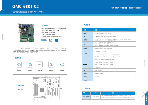
■产品规格项目描述处理器海光HG-3350处理器,主频3.0Ghz内存UDIMM x4,DDR4,最大可支持64GB,支持ECC显示功能独立显卡,提供VGA、HDMI显示输出(景嘉微7201、GT730、R7350、R5230)存储提供4个立式SATA接口,支持SATA3.0提供1个M.2插槽,可选配支持SATA&NVME SSD操作系统麒麟/UOS/Linux/Windows等操作系统IO接口4个USB2.0,4个USB3.0;2个RJ45千兆网口;2个RS232串口(可选扩展至4个)1组音频口:Line in x1+Line out x1+Microphone x1扩展插槽1个PCIEX16插槽(采用PCIE3.0X16信号)1个PCIE X8插槽(采用PCIE3.0X8信号)2个PCIE X4插槽(采用PCIE2.0X4信号)3个PCI插槽电源400W电源供电产品尺寸305mm X244mm工作温度-5℃∽60℃存储温度-40℃∽85℃■订购信息型号料号描述GM0-5601-02622-008-501002HG3350/3.0Ghz/DDR4DIMMx4/4x SATA3.0/M.22280/USB3.2*6/USB2.0*7/PS2/GPIO/LPT/COM*8/4*PCIE/MINIPCIEx1/3*PCI/AUDIO*3■产品特点•4条DDR4内存插槽(支持ECC);最大总支持64GB•2个千兆网口;最多支持4个COM串口•4个PCIE插槽,3个PCI插槽•外置4个USB2.0,4个USB3.0•支持麒麟、UOS、Windows等操作系统GM0-5601-02是采用海光处理器HG-3350设计的ATX工业大母板,主频3.0Ghz,支持四条DDR4内存,最大可支持64GB。
搭配独立显卡,支持VGA、HDMI显示输出,提供4个PCIE外部插槽,可支持主流网络扩展模块。
主板内部还提供M.2接口,可支持SSD模块。
EPC-9600I-L用户手册_V1.00
2. 系统基本操作........................................................................................................... 5
开机和登录 ............................................................................................................... 5 2.1.1 启动选择 ........................................................................................................... 5 2.1.2 串口连接设置 ................................................................................................... 5 2.1.3 串口登录 ........................................................................................................... 7 2.1.4 SSH 远程登录 .................................................................................................. 7 2.2 关机........................................................................................................................... 8 2.3 Qt 演示程序 .............................................................................................................. 9 2.4 输入设备 ................................................................................................................... 9 2.4.1 触摸屏和 USB 鼠标 ......................................................................................... 9 2.4.2 USB 键盘 .......................................................................................................... 9 2.5 查看系统信息 ........................................................................................................... 9 2.6 系统设置 ................................................................................................................. 10 2.6.1 网络设置 ......................................................................................................... 10 2.6.2 系统时钟 ......................................................................................................... 11 2.7 文件传输 ................................................................................................................. 11 2.7.1 SSH 文件传输 ................................................................................................ 11 2.7.2 NFS 文件传输 ................................................................................................ 12 2.8 U 盘使用 ................................................................................................................. 13 2.9 TF 卡使用 ............................................................................................................... 13 2.10 音频播放 ................................................................................................................. 13 2.11 U-Boot 交互 ............................................................................................................ 13 2.12 LCD 待机设置 ........................................................................................................ 14 2.13 LCD 背光调节 ........................................................................................................ 14 2.14 ADC ........................................................................................................................ 14 2.15 串口测试 ................................................................................................................. 15
PCS-9655_X_说明书_国内中文_国内标准版_X_R1.21
1.1 应用 ................................................................................................................................ 1
1.2 功能 ................................................................................................................................ 1
南京南瑞继保电气有限公司
技术支持,请联系: 电话:025-52107703、8008289967、4008289967 传真:025-52100770 或登陆网站:/ser_sup
公司地址:中国南京江宁区苏源大道 69 号 邮编:211102 公司网址:
我们对本文档及其中的内容具有全部的知识产权。除非特别授权,禁止复制或向第三方分发。凡侵犯本公司版权等知识产权的,本公司必 依法追究其法律责任。 我们定期仔细检查本文档中的内容,在后续版本中会有必要的修正。但不可避免会有一些错误之处,欢迎提出改进的意见。 我们保留在不事先通知的情况下进行技术改进的权利。
2.3 管理功能参数.................................................................................................................. 9
2.3.1 时钟性能参数....................................................................................................... 9
英特尔 台式机主板 DQ965CO 产品指南
文档结构
本《产品指南》包括以下各章内容: 1 台式机主板功能:概述产品的功能与特性 2 安装和更换台式机主板组件:提供有关安装本台式机主板及其它硬件组件的指导 3 更新 BIOS:提供有关更新 BIOS 的指导 4 为 RAID(Intel® Matrix Storage Technology(英特尔® 矩阵存储技术))进行配置:
LAN 子系统软件 ...........................................................................................18 RJ-45 LAN 连接器 LED 指示灯.........................................................................18 具备系统防御功能的 Intel® Active Management Technology(英特尔® 主动管理技术,
板上音频子系统 ....................................................................................................17 输入/输出 (I/O) 控制器 ........................................................................................17 LAN 子系统 ........................................................................................................18
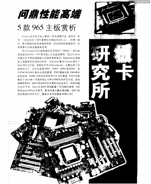
问鼎性能高端——5款965主板赏析
I cH8通过 I / o t l rHu cH IO C n r l b加 上符 合 o e
标 准 的C ODE C构 成 . 对 使 用 多 年 的 AC 7 HD 相 9 , l i 所 有 方 面 都 有 大 幅 度 性 能 提 升 。 HD Au dO在 — dO支 持 高 达 3 btl 2 Hz 样 率 最 高 7 1 道 i 2i 9K 采 / .声
双 通 道 DDR2 5 3 6 7 3 /6
l t 1 M A n e G Sl PP
Itl 9 5芯 片 组 . 要 加 入 了 对 Itl oe2 ne P 6 主 ne r C
I H8和 之 前 的 Itl 桥 芯 片 相 比 .具 有 六 大 C ne 南 规格 创 新 :
ne Bod tr95 tl ra wa 6 系列芯 片组 主要技术规格 e
技 术 ,将 只会 甩在 Q9 5 业平 台上 . 6企
4 I H8 C DH.基 于 I H8,但 加 入 了 I tl 快 C ne 的 速 重 启 技 术 和 VIV 技 术 。 I
—●一
G9 5 6
拥 有 独 家 的 F A (ne at mo yA c s )技 M Itl s Me r c e s F 术 .可 减 低 处 理 器 和 芯 片组 之 间 的 L tn y.增 加 ae c 内 存 带 宽 . 9 5 配 最 新 的 I H88 支 持 6个 c — P6搭 C /R. I E1 和 1 x 0个 Hi p e B 20.同 时 彻 底 放 弃 了 — e dUS . S AC 7 I 9 和 DE接 口 。
华为视频会议解决方案
华为高清视讯系统技术方案建议书临时方案华为技术有限公司2016年10月9日使用说明(2016.10.9):1、模板使用时根据实际客户需求和方案设计,选择相应章节内容,与实际方案不相关的内容需删除;2、模板中使用说明、备注部分为内部参考,具体制作面向客户提交的方案时,需删除所有使用说明、备注部分。
目录1视讯技术发展及应用需求 (5)1.1技术发展 (5)1.1.1视频 (5)1.1.2音频 (5)1.1.3组网 (5)1.2应用需求 (6)1.2.1高临场感体验 (6)1.2.2低带宽高清 (6)1.2.3良好的网络适应性 (6)1.2.4良好的易用性 (6)1.2.5稳定性和可维护性 (7)1.2.6标准开放和融合互通 (7)1.2.7支持多种线路接入方式 (7)1.2.8客户化、可定制 (7)2华为高清视讯系统需求分析 (7)2.1华为背景简介 (7)2.2华为网络现状分析 (8)2.3华为客户需求分析 (8)3 华为高清视频系统设计方案建议 (8)3.1系统设计依据 (8)3.2系统设计原则 (11)3.3方案四SMC2.0+MCU96X0 ................................................................... 错误!未定义书签。
3.4系统组网方案四配置清单 ...................................................................... 错误!未定义书签。
4华为高清视频系统主要功能及特点 (12)4.1良好的高清晰音视频沟通体验 (12)4.1.1全高清108060端到端解决方案 (12)4.1.2高流畅性 (12)4.1.3强大全编全解处理能力,最大限度支持动态速率、协议适配 (13)4.1.4VME+H.264 HP 低带宽高清 (13)4.1.5H.264 SVC技术 (14)4.1.6高清1080P60FPS静态/动态双流 (14)4.1.7高保真,立体声,CD音质效果 (15)4.2丰富的会议召集模式 (15)4.2.1主叫呼集 (15)4.2.2匿名会议(电话会议模式) (16)4.2.3管理员调度 (16)4.2.4网络预约 (16)4.2.5视音频IVR导航与ad-hoc创建和加入会议 (16)4.2.6特服号入会 (16)4.2.7Outlook预约会议 (16)4.2.8云化资源池管理实现会议智能调度 (16)4.3良好的网络适应性 (18)4.3.1超强纠错(SEC 2.0-- Super Error Concealment) (18)4.3.2超强纠错(SEC 3.0-- Super Error Concealment) (18)4.3.3智能调速(IRC--Intelligent Rate Control) (19)4.3.4断线恢复(RoD--Reconnect on Disconnect) (19)4.3.5丢包重传(ARQ--Automatic Repeat reQuest) (20)4.4简单易用 (20)4.4.1用户界面简约时尚 (20)4.4.2PAD智能操控平台 (20)4.4.3丰富的会议控制功能 (20)4.4.4会议模板预置功能 (21)4.4.5字幕与横幅功能 (22)4.4.6一屏三显,节约投资 (22)4.4.7多视一流功能 (22)4.4.8无线辅流,轻松共享数据 (23)4.4.9支持WIFI呼叫及无线麦克 (23)4.4.10USB零配置 (24)4.4.11全景会场功能 (25)4.4.12多组多画面(on-table多画面) (25)4.4.13图形化操作界面 (25)4.4.14软终端随时随地接入会议 (26)4.4.153G-SDI接口实现1080P60fps远距离传输 (28)4.5安全稳定 (28)4.5.1产品成熟 (28)4.5.2系统稳定 (29)4.5.3多重加密 (30)4.5.4系统安全 (30)4.5.5资源池会议备份 (32)4.6管理维护方便 (33)4.6.1分级分权,大网维护简单 (33)4.6.2Nlog网络线路实时监控 (37)4.6.3支持WEB管理 (37)4.6.4系统设备拓扑图生成管理 (37)4.6.5系统设备配置批量升级及备份 (37)4.6.6系统告警和日志管理 (38)4.7标准互通 (39)4.7.1采用国际标准协议 (39)4.7.2支持TIP协议,与思科网真互通 (39)4.7.3华为视讯产品互联互通能力介绍 (39)4.7.4支持与微软UC系统互通 (41)4.7.5端到端IMS融合解决方案 (42)4.8丰富组网 (42)4.8.1支持多种接入方式 (42)4.8.2最大5级和超强多通道级联能力 (43)4.8.3支持大容量语音接入,满足在外人员接入视频会议需求 (43)4.8.4支持高清录制点播功能 (44)4.8.5支持软件化部署的管理平台 (48)4.8.6完善的公私网穿越解决方案 (49)4.9专业定制 .................................................................................................. 错误!未定义书签。
触摸屏收款机说明书

目录
第 1 章 第四代嵌入式触摸屏收款机简介 ............................................................................................................... 1 1.1 基本技术参数 .............................................................................................................................................. 1 1.2 主要特点 ...................................................................................................................................................... 1 1.3 主要性能 ...................................................................................................................................................... 1 1.4 机器使用流程图 .......................................................................................................................................... 2
第 2 章 后台管理 ..................
关于NAS965技术要点

NAS-965自动准同期装置05/08/01 方大富一、外观介绍:1、面板:(1)“电源”行:“+5V”“+15V”“-15V”“+24V”灯显示装置本身内部元件的工作电源状态;“故障”灯的显示既代表装置本身硬件的永久故障又代表装置工作过程中出现的一些非法操作及SOE报警(详细内容在后面的说明中会一一提到)(2)“工作方式”行:“试验”表示装置处试验模式或正常待机模式;“导前时间”表示装置处于测量导前时间的工作模式下;“无压合闸”表示装置将进行无压合闸(无压分单侧无压及两侧均无压);“现地同期”表示装置处于在液晶面板里手动进行强制同期的工作模式下;“远方同期”表示装置处于接收外部开入量申请而进行的自动同期模式下。
(3)“输出状态”行:“升压”表示装置在进行调节同期时对机组进行微调升压输出;“降压”表示装置在进行调节同期时对机组进行微调降压输出;“增速”表示装置在进行调节同期时对机组进行微调增速(增频)输出;“减速”表示装置在进行调节同期时对机组进行微调减速(减频)输出;“合闸”表示装置在认为满足同期条件时发合闸脉冲(约保持1.5秒)。
(4)键盘:初始化参数存储器:R键和-、+键同时按下,先松R键,再松-和+键,输入密码(C 和E同时按下);设置单机(只认第一个同期点)工作模式:R键和-键同时按下,先松R键,再松-键,输入密码(C和E同时按下);设置多机(支持16个同期点)工作模式:R键和+键同时按下,先松R键,再松+键,输入密码(C和E同时按下)。
2、背板:(从左往右看)(1)交流模件(第3块):对外有四个接线端子,从上往下是TMA、TMB、TMA’、TMB’,TMA和TMB是运行系统电压输入,TMA’和TMB’是待并系统电压输入,支持100V与100V并、100V 与57.7V并、57.7V与100V并、57.7V与57.7V并(以后有详细介绍)。
(2)信号模件(第4块):主要进行自产试验电压频率信号和对试验及实际信号进行选择进入“信号处理模件”。
中兴S330硬件手册及应用
资料名称
产品版本
V1.2
您单位安装该设备的时间
ZXMP S330(V1.2)基于 SDH 的多业务节点设备 硬件手册
资料版本
20060325-R1.0
为了能够及时与您联系,请填写以下有关您的信息
姓名
单位名称
邮编
单位地址
电话
好
较好
一般
较差
差
总体满意
工作指导
您对本资料 的评价
查阅方便 内容正确 内容完整
声明
本资料著作权属中兴通讯股份有限公司所有。未经著作权人书面许可,任何单位或 个人不得以任何方式摘录、复制或翻译。
侵权必究。
和
是中兴通讯股份有限公司的注册商标。中兴通讯产品的名称和标志是
中兴通讯的专有标志或注册商标。在本手册中提及的其他产品或公司的名称可能是其各
自所有者的商标或商名。在未经中兴通讯或第三方商标或商名所有者事先书面同意的情
资料名称产品版本v12您单位安装该设备的时间zxmps330v12基于sdh的多业务节点设备硬件手册资料版本20060325r10为了能够及时与您联系请填写以下有关您的信息姓名邮编电话总体满意工作指导您对本资料的评价查阅方便内容正确内容完整结构合理图表说明通俗易懂内容结构内容详细您对本资料的改进建议内容深度表达简洁增加图形增加实例增加faq其他您对中兴通讯用户资料的其他建议单位名称单位地址较好一般详细说明较差差email好前言手册说明内容介绍本手册适用于unitranszxmps330v12基于sdh的多业务节点设备以下简称zxmps330
3. 《Unitrans ZXMP S330(V1.2)基于 SDH 的多业务节点设备 安装手册》 介绍设备的工程安装步骤,包括安装准备、硬件安装、线缆布放、安装检 查、设备上下电的具体操作。
集特智能飞腾主板汇总

工控平台
1.GM9-2602 2.GM9-2602-20 3.GM9-2602-21 4.GM9-2602-22 5.GM7-2602-02 6.GM7-2602-20 7.GM7-2602-21
1.
GM9-2602 飞腾FT 2000/ 4(兼容D2000/ 8)处理器的Micro ATX工控主板,主频可达2.6Ghz
6.
GM7-2602-20
全国产化飞腾D2000八核处理器标准miniITX主板
7.
GM7-2602-21
全国产化飞腾D2000八核处理器+x100桥片miniITX标准板
Come平台
1.GCE-2001
2.GCE-2001-01
1.
GCE-2001
全国产化飞腾D2000八核处理器的COMe 核心板
2.
GM9-2602-20
飞腾D2000八核处理器+X100桥片Micro ATX主板
3.
GM9-2602-21
飞腾D2000八核处理器+X100桥片Micro ATX主板
4.
GM9-2602-22
全国产化飞腾D2000八核处理器+X100桥片标准MATX主板
5.
GM7-2602-02
国产飞腾D2000八核处理器M-ITX工控主板
飞腾主板汇总
北京集特智能科技有限公司
目录
01 通用平台 02 工控平台 03 Come平台
通用平台
1.GM9-2002
2.GM7-2604
1.
GM9-2002
飞腾 D2000 处理器 Micro ATX 主板;3 个 PCIE ,支持银河麒麟、 UOS 等国产操作系统
2.
GM7-2604
H3C光模块介绍
目录1可插拔模块简介 .................................................................................................................................................................................................................... 1-11.1 H3C高端网络产品支持的可插拔模块类型 ................................................................................................................................................................................. 1-11.2 光模块概念介绍 ......................................................................................................................................................................................................................... 1-21.2.1 简介................................................................................................................................................................................................................................. 1-21.2.2 传输速率(Data Rate).................................................................................................................................................................................................. 1-21.2.3 传输距离 ......................................................................................................................................................................................................................... 1-21.2.4 中心波长 ......................................................................................................................................................................................................................... 1-31.2.5 光纤类型 ......................................................................................................................................................................................................................... 1-31.2.6 接口连接器类型 .............................................................................................................................................................................................................. 1-41.2.7 接口指标 ......................................................................................................................................................................................................................... 1-51.3 电口模块概念介绍 ..................................................................................................................................................................................................................... 1-51.3.1 千兆电口模块简介........................................................................................................................................................................................................... 1-52 SFP模块 ............................................................................................................................................................................................................................... 2-12.1 1000M SFP光模块 .................................................................................................................................................................................................................... 2-12.1.1 外观图 ............................................................................................................................................................................................................................. 2-12.1.2 具体型号及规格 .............................................................................................................................................................................................................. 2-22.2 100M SFP光模块 ...................................................................................................................................................................................................................... 2-22.2.1 外观图 ............................................................................................................................................................................................................................. 2-22.2.2 具体型号及规格 .............................................................................................................................................................................................................. 2-32.3 155M SFP光模块 ...................................................................................................................................................................................................................... 2-32.3.1 外观图 ............................................................................................................................................................................................................................. 2-32.3.2 具体型号及规格 .............................................................................................................................................................................................................. 2-32.4 622M SFP光模块 ...................................................................................................................................................................................................................... 2-42.4.1 外观图 ............................................................................................................................................................................................................................. 2-42.4.2 具体型号及规格 .............................................................................................................................................................................................................. 2-42.5 2.5G SFP光模块........................................................................................................................................................................................................................ 2-42.5.1 外观图 ............................................................................................................................................................................................................................. 2-42.5.2 具体型号及规格 .............................................................................................................................................................................................................. 2-52.6 155M/1000M BIDI模块 .............................................................................................................................................................................................................. 2-52.6.1 外观图 ............................................................................................................................................................................................................................. 2-52.6.2 具体型号及规格 .............................................................................................................................................................................................................. 2-62.7 1000M CWDM模块 ................................................................................................................................................................................................................... 2-72.7.1 外观图 ............................................................................................................................................................................................................................. 2-72.7.2 具体型号及规格 .............................................................................................................................................................................................................. 2-72.8 SFP电口模块............................................................................................................................................................................................................................. 2-82.8.1 外观图 ............................................................................................................................................................................................................................. 2-82.8.2 具体型号及规格 .............................................................................................................................................................................................................. 2-83 SFP+模块 ............................................................................................................................................................................................................................. 3-13.1 SFP+光模块 .............................................................................................................................................................................................................................. 3-13.1.1 外观图 ............................................................................................................................................................................................................................. 3-13.1.2 具体型号及规格 .............................................................................................................................................................................................................. 3-13.2 SFP+电缆 .................................................................................................................................................................................................................................. 3-23.2.1 外观图 ............................................................................................................................................................................................................................. 3-23.2.2 具体型号及规格 .............................................................................................................................................................................................................. 3-24 XFP模块 ............................................................................................................................................................................................................................... 4-14.1 外观图 ....................................................................................................................................................................................................................................... 4-14.2 具体型号及规格 ......................................................................................................................................................................................................................... 4-21 可插拔模块简介1.1 H3C 高端网络产品支持的可插拔模块类型H3C 高端网络产品支持的可插拔模块类型如表1-1所示。
pro-face sp5000系列 硬件手册说明书

目录
SP5000-MM01-CS-PDF_O
安全信息 ....................................................................................................7 关于本书 ....................................................................................................8 概述......................................................................................................... 11
对于将本指南或其内容用作商业用途的行为,施耐德电气未授予任何权利或许可,但 以“原样”为基础进行咨询的非独占个人许可除外。
施耐德电气的产品和设备应由合格人员进行安装、操作、保养和维护。
由于标准、规格和设计会不时更改,因此本指南中包含的信息可能会随时更改,恕不 另行通知。
在适用法律允许的范围内,对于本资料信息内容中的任何错误或遗漏,或因使用此处 包含的信息而导致或产生的后果,施耐德电气及其附属公司不会承担任何责任或义 务。
标准主机模块 ................................................................................28 增强型主机模块............................................................................. 30 开放型主机模块............................................................................. 32 LED 指示 ......................................................................................34 显示模块 ............................................................................................35 精良显示模块 ................................................................................35 高级显示模块 ................................................................................39 LED 指示 ......................................................................................42 规格......................................................................................................... 44 一般规格 ............................................................................................44 电气规格....................................................................................... 44 环境规格....................................................................................... 46 结构规格....................................................................................... 47 功能规格 ............................................................................................49 显示规格....................................................................................... 49 存储器 ..........................................................................................51 时钟 .............................................................................................51 触摸屏 ..........................................................................................51 接口规格 ............................................................................................52 接口规格....................................................................................... 52 接口连接....................................................................................... 54 用于 COM1/COM2 的串行接口 (RS-232C 和 RS-422/RS485) .............................................................................................57 辅助输出/扬声器输出接口 (AUX) ....................................................59 DVI-D 输出接口.............................................................................60 尺寸......................................................................................................... 62 标准主机模块...................................................................................... 62 SP-5B00 ......................................................................................62 增强型主机模块 ..................................................................................63 SP-5B10 ......................................................................................63 开放型主机模块 ..................................................................................63
中山智达自动化 ePLC-M196-12M 嵌入式可编程控制器手册说明书
Automate Now!And discover real freedom…Embedded Controller嵌入式可编程控制器ePLC-M196-12M使用手册MANUAL(V1.00), 2007/01中山智达自动化ZDAUTO Automation Technilogy Co.,LTD. 公司地址: 中山市莲塘东路城市花园宝兴阁壹号A座二层. TEL : 0760 -8718228 FAX : 8711675门市地址: 中山市莲兴路19号之10, 邮编:528402. E-mail: ***************, ****************缪立循 著目录Page1 产品概述 - - - - - - - - - - - - - - - - - - - - - - - - - 22 产品特点 - - - - - - - - - - - - - - - - - - - - - - - - - 33 技术指标 - - - - - - - - - - - - - - - - - - - - - - - - - 33.1 电气指标 - - - - - - - - - - - - - -- - - - - - - - - 33.2 性能指标 - - - - - - - - - - - - - - - - - - - - - - 33.3 电气接线图和选点- - - - - - - - - - - - - - - - - - - 33.4 选型说明点- - - - - - - - - - - - - - - - - - - - - - 44 软件支持- - - - - - - - - - - - - - - - - - - - - - - - - 55 安装与配线-- - - - - - - - - - - - - - - - - - - - - - - - 55.1 安装尺寸- - - - - - - - - - - - - - - - - - - - - - - 55.2 电源的正确配线- - - - - - - - - - - - - - - - - - - 65.3 输入电路的正确配线- - - - - - - - - - - - - - - - - - 65.3.1 开关量输入特性- - - - - - - - - - - - - - - - - - 65.3.2 脉冲量输入电路特性- - - - - - - - - - - - - - - - 65.3.3 模拟量输入电路特性- - - - - - - - - - - - - - - - 75.4 输出电路的正确配线- - - - - - - - - - - - - - - - - - 85.4.1 继电器输出电路- - - - - - - - - - - - - - - - - - 85.4.2 大功率晶体管集电极开路输出电路- - - - - - - - - - 85.4.3 小功率晶体管集电极开路输出电路- - - - - - - - - - 85.4.4 光偶集电极开路输出电路- - - - - - - - - - - - - - 85.4.5 光隔可控硅输出电路- - - - - - - - - - - - - - - - 85.4.6 脉冲量输出特性光偶集电极开路输出电路- - - - - - - 85.4.7 模拟量输出特性- - - - - - - - - - - - - - - - - - 85.5 通讯口电路特性- - - - - - - - - - - - - - - - - - - 95.6 扩展模块的使用- - - - - - - - - - - - - - - - - - - 95.7 人机界面的连接- - - - - - - - - - - - - - - - - - - 91、产品概述ePLC-M196-12M系列的嵌入式可编程控制器, 是智达公司专为中小型自动化控制系统而设计的控制器,这款可编程控制器,采用工业级设计的SOM196核芯模块,外部可达288点的I/O接口采用标准模块构造而成,另外,该控制器的输入输出接口信号类型包括了常规的开关量外,还具有模拟量、脉冲量的接口,它涵盖了大多数的电气接口,可在各行各业中灵活地使用,它可提供RS485网络通迅接口,能全面实现联网系统,它也具备人机界面的通迅接口,由于它的可靠性,可编程、具备完善的电气接口,满足了各种机型的要求, ePLC-M196-12M是久经现场考验的、具备良好的性能价格比的控制器。
能不能给我965主板支持cpu的表格
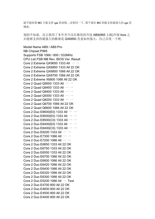
能不能给我965主板支持cpu的表格…还想问一下,那个现在965的板支持最强大的cpu是哪款,别的不知道,反正我用了5年至今还在服役的升技AB9(965主板)升级bios之后能够支持的最强大的酷睿是QX6850.究竟如何强大,自己百度一下吧.Model Name AB9 / AB9 ProNB Chipset P965Supports FSB 1066 / 800 / 533MHzCPU List FSB MB Rev. BIOS Ver. ResultCore 2 Extreme QX9650 1333 All 一一Core 2 Extreme QX6850 1333 All 22 OKCore 2 Extreme QX6800 1066 All 22 OKCore 2 Extreme QX6700 1066 All 22 OKCore 2 Extreme X6800 1066 All 22 OKCore 2 Quad Q9550 1333 All 一一Core 2 Quad Q9450 1333 All 一一Core 2 Quad Q9400 1333 All 一一Core 2 Quad Q9300 1333 All 一一Core 2 Quad Q8200 1333 All 一一Core 2 Quad Q6700 1066 All 22 OKCore 2 Quad Q6600 1066 All 22 OKCore 2 Duo E8600(E0) 1333 All 一一Core 2 Duo E8500(E0) 1333 All 一一Core 2 Duo E8500(C0) 1333 All 一一Core 2 Duo E8400(E0) 1333 All 一一Core 2 Duo E8400(C0) 1333 All 一一Core 2 Duo E8200 1333 All 一一Core 2 Duo E7300 1066 All 一一Core 2 Duo E7200 1066 All 一一Core 2 Duo E6850 1333 All 22 OKCore 2 Duo E6750 1333 All 22 OKCore 2 Duo E6550 1333 All 22 OKCore 2 Duo E6700 1066 All 22 OKCore 2 Duo E6600 1066 All 22 OKCore 2 Duo E6420 1066 All 22 OKCore 2 Duo E6400 1066 All 22 OKCore 2 Duo E6320 1066 All 22 OKCore 2 Duo E6300 1066 All 22 OKCore 2 Duo E5200 1066 All 一TestCore 2 Duo E4700 800 All 22 OKCore 2 Duo E4600 800 All 22 OKCore 2 Duo E4500 800 All 22 OKCore 2 Duo E4400 800 All 22 OKCore 2 Duo E4300 800 All 22 OK Pentium Dual Core E2220 800 All 22 OK Pentium Dual Core E2200 800 All 22 OK Pentium Dual Core E2180 800 All 22 OK Pentium Dual Core E2160 800 All 22 OK Pentium Dual Core E2140 800 All 22 OK Celeron 440 800 All 22 OKCeleron 430 800 All 22 OKCeleron 420 800 All 22 OKPentium EE 965 1066 All 22 OK Pentium EE 955 1066 All 22 OK Pentium EE 840 800 All 22 OK Pentium D 960 800 All 22 OKPentium D 950 800 All 22 OKPentium D 945 800 All 22 OKPentium D 940 800 All 22 OKPentium D 930 800 All 22 OKPentium D 920 800 All 22 OKPentium D 840 800 All 22 OKPentium D 830 800 All 22 OKPentium D 820 800 All 22 OKPentium D 805 533 All 22 OKPentium 4 EE 3.73GHz 1066 All 22 OK Pentium 4 661 800 All 22 OKPentium 4 651 800 All 22 OKPentium 4 641 800 All 22 OKPentium 4 631 800 All 22 OKPentium 4 672 800 All 22 OKPentium 4 670 800 All 22 OKPentium 4 662 800 All 22 OKPentium 4 660 800 All 22 OKPentium 4 650 800 All 22 OKPentium 4 640 800 All 22 OKPentium 4 630 800 All 22 OKPentium 4 571/ 570/J 800 All 22 OK Pentium 4 561/ 560/J 800 All 22 OK Pentium 4 551/ 550/J 800 All 22 OK Pentium 4 541/ 540/J 800 All 22 OK Pentium 4 531/ 530/J 800 All 22 OK Pentium 4 521/ 520/J 800 All 22 OK Pentium 4 519 533 All 22 OKPentium 4 506 533 All 22 OKPentium 4 505/J 533 All 22 OKCeleron D 365 533 All 22 OKCeleron D 356 533 All 22 OK Celeron D 347 533 All 22 OK Celeron D 351/350 533 All 22 OK Celeron D 346/345/J 533 All 22 OK Celeron D 341/340/J 533 All 22 OK Celeron D 336/335/J 533 All 22 OK Celeron D 331/330/J 533 All 22 OK Celeron D 326/325/J 533 All 22 OK Celeron D 320 533 All 22 OK Celeron D 315 533 All 22 OK Celeron D 320 533 All 22 OK Celeron D 315 533 All 22 OK。
电源块STRG9656详细资料
电源块STRG9656详细资料本机电源电路使用三肯公司新一代的厚膜电源电路STR-G9656。
G9656的工作原理和STR-F6656一致。
由于采用了新的制造工艺,使其体积更加减小,易于实现电源的小型化,标准化。
9-1主要特点1.内藏高精度误差放大器,减少电源的元件数量。
2.微小IC起动电流(100μA max)3.搭载PRC工作方式用的振荡器。
4.内藏低通有源滤波器,使电源在轻负荷时能稳定工作。
5.采用雪崩击穿能量保证,高破坏耐量的功率MOSFET6.内藏MOSFET软驱动电路。
7.内藏MOSFET定电压驱动电路。
8.丰富的保护功能:OCP、OVP、TSD9-2 STR-G9656电路方框图9.3 各端子功能:端子号符号名称功能1 D 漏极端子MOSFET漏极端子2 S 源极端子MOSFET源极端子3 GND GND端子GND 4 VIN 电源端子控制电路的电源输入5 OCP/FB 过电流/反馈端子过电流检出信号及定电压控制信号输入9.4 工作原理交流电源经C501、C502、L502组成的EMC网络,到达VD503~VD506组成的全桥电路,由C507进行滤波,形成约300V的直流电压。
整流后的电压从变压器的3脚输入,从7脚输出至G9656的1脚(D),C511、VD511、C512、R525为初级线圈的泻放电路,减少对电容和G9656的电压冲击。
C513为谐振电容,调整它可以,调整G9656导通时的1脚的电压,减少开关损耗,降低温升。
开机瞬间,G9656的VIN由R510、R511、C508提供,由于启动时需要的电流小,因此可以启动。
启动后由辅助绕组经VD512整流形成约18V的VIN电压,保证正常工作。
R522与R523并联做过流保护电阻,G9656通过检测其上的电压和R521的电压的和监测过流状态。
R522和R523并联电阻R同时限定电路的最大电流0.73/R。
次级输出4组电压:10脚. +B:130V 13脚小信号:+14.5V 14脚伴音:+15V12脚场工作电压:+27V。
