TMS320C6713管脚分类速查中文手册-1
浅谈TMS320C6713的多路CVSD语音编解码
64 Kb/s的A律或μ律的对数压扩PCM编码在大容量的光纤通信系统和数字微波系统中已得到广泛应用,但由于占用较大的传输带宽和具有复杂的成帧结构。
CVSD调制以其较低的应用难度、成本和编码速率,较好的语音质量广泛应用于战术通信网、卫星通信、蓝牙等无线语音传输领域。
于是不同码制的网络之间的互连对两种码制之间的转换提出了更高的要求。
针对近年来FPGA、DSP技术的不断发展,本文提出了一种满足此需求的设计方案,以适应通信技术日新月异的发展。
1 多路数据信号的收发1.1 McASP(Multichannel Audio Serial Port)McASP是美国TI公司的DSP的一种接入接口。
称为复通道音频接入接口。
这是一种通用的音频接入接口。
采用的是时分复用的数据流形式。
McASP使用IIS协议,也支持DIT协议。
McASP包括发射与接收两部分,它们可以使用不同时钟,不同传输模式,工作完全独立。
发射和接受能够工作在同步状态,此外,McASP的管脚能被配置成通用I/O 管脚。
McASP使用相当灵活,能够和音频模数转换(ADC),数模转换(DAC),编码器,数字音频接口接收器(DIR)等无缝直连。
例如DIR接收,一个DIR接收器集成电路需要使用IIS输出格式,并且和McASP接受部分相连。
McASP在C5000系列DSP(是一种独特的微处理器,是以数字信号来处理大量信息的器件)处理器基础上新增加的一个专门用来实现多通道音频应用的通用串行端口,它包括收/发两个功能部件,二者问即可完全同步也可各自采用完全独立的主时钟、位时钟和帧同步时钟,具备不同的数据传输模式和位码流格式。
支持多种数据协议:I2S,S/PDIF,IEC60958-1,AES-3等格式码流,支持时分复用(TDM码流),多达32个通道进行收发传输的字长可以是8位/12位/16位/120位/24位/32位等。
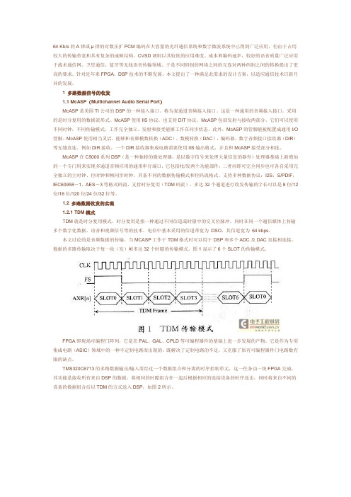
1.2 多路数据收发的实现1.2.1 TDM模式TDM就是时分复用模式。
DSP(TMS320C6713)入门之旅五、I2C的理解和使用
一般DSP上面都集成了I2C模块,这样在连接外部器件时可以很方便的控制外部的器件。
I2C 基本上都是用于外部控制的,因为是是串行总线。
在我们的实验板上I2C总线连接到了两个从设备上面,一个是我们的eeprom,另一个是我们的音频芯片AIC23。
通过I2C协议我们写入和读取eeprom数据,控制AIC23的声音一些属性!简介一下I2C协议的规则:一. 技术性能:工作速率有100K和400K两种;支持多机通讯;支持多主控模块,但同一时刻只允许有一个主控;由数据线SDA和时钟SCL构成的串行总线;每个电路和模块都有唯一的地址;每个器件可以使用独立电源二. 基本工作原理:以启动信号START来掌管总线,以停止信号STOP来释放总线;每次通讯以START开始,以STOP结束;启动信号START后紧接着发送一个地址字节,其中7位为被控器件的地址码,一位为读/写控制位R/W,R/W位为0表示由主控向被控器件写数据,R/W为1表示由主控向被控器件读数据;当被控器件检测到收到的地址与自己的地址相同时,在第9个时钟期间反馈应答信号;每个数据字节在传送时都是高位(MSB)在前;写通讯过程:1. 主控在检测到总线空闲的状况下,首先发送一个START信号掌管总线;2. 发送一个地址字节(包括7位地址码和一位R/W);3. 当被控器件检测到主控发送的地址与自己的地址相同时发送一个应答信号(ACK);4. 主控收到ACK后开始发送第一个数据字节;5. 被控器收到数据字节后发送一个ACK表示继续传送数据,发送NACK表示传送数据结束;6. 主控发送完全部数据后,发送一个停止位STOP,结束整个通讯并且释放总线;读通讯过程:1. 主控在检测到总线空闲的状况下,首先发送一个START信号掌管总线;2. 发送一个地址字节(包括7位地址码和一位R/W);3. 当被控器件检测到主控发送的地址与自己的地址相同时发送一个应答信号(ACK);4. 主控收到ACK后释放数据总线,开始接收第一个数据字节;5. 主控收到数据后发送ACK表示继续传送数据,发送NACK表示传送数据结束;6. 主控发送完全部数据后,发送一个停止位STOP,结束整个通讯并且释放总线;DSP中IIC模块框图:1. 总线空闲状态SDA和SCL两条信号线都处于高电平,即总线上所有的器件都释放总线,两条信号线各自的上拉电阻把电平拉高;2. 启动信号START时钟信号SCL保持高电平,数据信号SDA的电平被拉低(即负跳变)。
DSP(TMS320C6713)入门之旅三、中断的理解和使用

学习一个芯片的功能时,我的建议是先学会如何用C语言点亮一个LED灯,然后就是学习一下使用他的中断,因为在做芯片的时候,各个厂家有自己的一套自己的方法。
所以使用中断的就必须了解很多概念,比如如何打开中断,如何安装自己的中断子服务程序,等等!先介绍一下什么叫中断:你在下象棋,突然电话响了,你回屋接电话,然后回来继续下象棋,这个过程就叫做中断响应过程(中断过程)。
CPU执行正常任务———————下象棋保护现场———————————-你已经想好要―将军‖,先在脑海中记下来。
中断发生———————————-电话响-中断服务程序—————————-接电话恢复现场———————————-回来后恢复刚才想法中断返回———————————-你回来继续下象棋中断屏蔽———————————-Boss 正在训话,要求所有电话关机,你不能接电话了。
非屏蔽中断——————————-你内急,即使是Boss 在训话,你还是得到外面去嘘嘘。
可屏蔽中断——————————-你在―闭关修炼‖,可以不受外界干扰所以我们在使用中断之前先得告诉CPU,我们要使用那个中断,当中断发生的时候,你的执行程序的去向(也就是中断服务子程序),最后在返回我们被中断的函数。
这样就完成了我们的中断历程!看看6713执行中断的流程:一、使能了全局中断和子中断,那么CPU每执行一条指令之前就去查询一下有没有中断被置位,如果有产生的,那么CPU就要跳转!二、软件把CPU内部的寄存器A0~A15,B0~B15,等等这些寄存器的值推入堆栈保存,把当前PC寄存器的值放入IRP寄存器中以备中断返回能找到当前被打断的位置(保存现场,中断函数前面得加interrupt关键字)三、CPU的PC指针读出中断向量表的地址,也就是把(ISTP寄存器的值+子中断向量偏移量)装入PC寄存器,这样就执行跳转。
四、在中断向量表里一般有就用跳转指令,这样就可以跳转到我们用C语言编写的中断服务子程序中。
一种高性能浮点DSP芯片TMS320C6713及其最小系统的设计
一种高性能浮点DSP芯片TMS320C6713及其最小系统的设计TMS320C6713是美国德州仪器公司(TI)继TMS320C62X系列定点DSP芯片后开发的一种32 bit新型浮点DSP芯片,该芯片的内部结构在TMS320C62X基础上改进,具有如下革命性的特点:(1)处理速度快,工作主频最高可达到300 MHz,峰值运算能力为2 400 MIPS/1 800 MFLOPS;(2)硬件支持IEEE格式的32 bit单精度与64 bit双精度浮点操作;(3)集成了32×32 bit的乘法器,其结果可为32 bit或64 bit;(4)TMS320C62X指令无需任何改变即可在TMS320C6713上运行。
1结构特点TMS320C6713是TI新推出的高速浮点DSP,工作主频200 MHz,其单指令执行周期仅5 ns;具有强大的定点浮点运算能力,运算速度可达1 600 MIPS/1 200 MFLOPS。
与TMS320其他系列DSPs相比,C6000系列DSPs最主要的特点是在体系结构上采用了VelociTI超长指令字VLIW(Very long Instruction Word)结构,VLIW体系结构中,是由一个超长的机器指令字来驱动内部的多个功能单元的(这也是VLIW名字的由来)。
每个指令字包含多个字段(指令),字段之间相互独立,各自控制一个功能单元,因此可以单周期发射多条指令,实现很高的指令级并行效率。
C6000的VLIW采用了类RISC指令集,使用大统一的寄存器堆,结构规整,具有潜在的易编程性和良好的编译性能,在科学应用领域可以发挥良好的性能。
TMS320C6713是一种支持浮点运算的DSP芯片,是德州仪器公司设计的用于高端处理的长指令、多功能的DSP芯片。
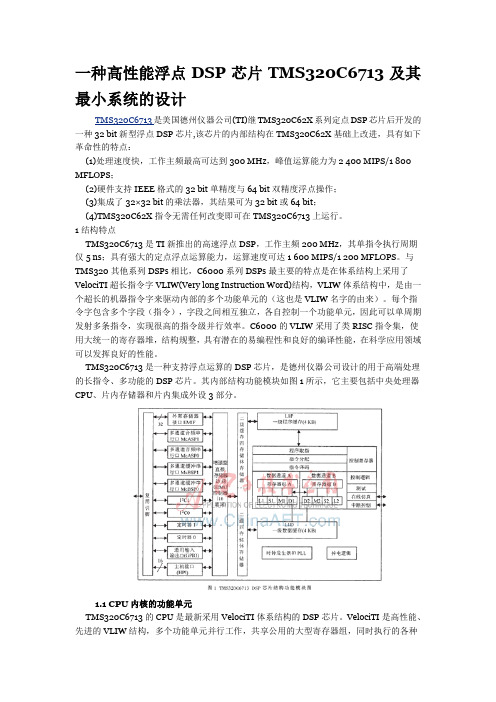
其内部结构功能模块如图1所示,它主要包括中央处理器CPU、片内存储器和片内集成外设3部分。
1.1 CPU内核的功能单元TMS320C6713的CPU是最新采用VelociTI体系结构的DSP芯片。
第五章 TMS320C6713指令系统(给力)

第五章 TMS320C6713指令系统百元滴 Design By 心海夜帆5.3.3指令集表如表5-14所示列出了可用于C6x的定点和浮点处理器的操作指令,并根据它们所使用的功能单元进行分类。
表5-14 定点和浮点处理器的操作指令.L单元 .M单元 .S单元 .D单元ABS ADD ADDU AND CMPEG CMPGT CMPGTU CMPLT CMPLTG LMBD MV NRG NORM NOT MPYMPYHMPYHLMPYHLUMPYHSLUMPYHSUMPYHUMPYHULSMPYHUSMPYLHMPYLHUMPYLSHUMPYSUHSMPYSUADDADDKADD2ANDB dispB IRP**B NRP**B regCLREXTEXTUMVMVC*MVKADDADDABADDAHADDAWLDBLDBULDHLDHULDWLDB(15-bitoffset)**LDBU(15-bit offset)**LDH(15-bit offset)**LDHU(15-bit offset)**LDW(15-bit offset)**OR SADD SAT SSUB SUB SUBU SUBC XOR ZERO MPYUMPYUSSMPYSMPYHSMPYHLSMPYLHMVKHMUVLHNEGNOTORSETSHLSHRSHRUSSHLSUBSUBUSUB2XORZEROMVSTB(15-bit offset)**STH(15-bit offset)**STW(15-bit offset)**STBSTHSTWSUBSUBABSUBAHSUBAWZERO*:只适用于S2;**只适用于D2。
TMS320C6713的指令集可以进行字节寻址,获得8位、16位、32位数据,因此存储器可以得到充分的利用。
指令集中有位操作,包括位域抽取、设置、清除,以及位计数、归一化等。
所有的指令都是条件执行指令,可以根据某种条件决定是否执行。
一种高性能浮点DSP芯片TMS320C6713及其最小系统的设计

?}竺量:竺耋兽去。 2・2竺萋竺焉烹銎。.。。.。。 +。。。。。+。。 。;。套辇翼竺慧攀銎三。,。鼍象专鬯D。。S+P竺兰寰序要譬
≤芸;菱裔善囊萎;’溢≤毒蓊。军茹嘉瘩LSC器菩莴盖;
笔芝甚;姜薹赛嘉-薪苡蒙南黼}菖笔蒌尽昌磊薹三霁 储i"器la:F气蕊;‘石善;蒹磊三!”…“4。。、…。“““
级—
四
●
脚
叫定时器1 I.+ Hl定时器0卜◆
+—叫通用输入k+
l输出VI(GPIO)l
卜
存 储
体
叫f
级搬存攀JI
{时钟发生器和PLL} I掉电逻辑l
存
储
叫黹口卜
器
图1 TMS320C6713
DSP芯片结构功能模块罔
执行的各种操作是由VLIW的长指令分配模块进行同 步协调的,这种结构使其成为多通道、多功能以及高性 能应用的首选器件。,CPU内核作为DSP芯片的运算和控 制中心,包括以下几部分:(1)程序取指令单元、指令分 配单元、指令译码单元;(2)2个数据通道A、B,每个通道 中包括*个由16个32 bit寄存器组成的寄存器组和4
800MFLOPS;
要的特点是在体系结构上采用了VelociT!超长指令字 VLIW(Very
long Instruction
Word)结构,VLIW体系结构
中,是由一个超长的机器指令字来驱动内部的多个功能 单元的(这也是VLIW名字的由来)。每个指令字包含多 个字段(指令),字段之间相互独立,各自控制一个功能 单元,因此可以单周期发射多条指令,实现很高的指令 级并行效率。C6000的VLIW采用了类RISC指令集,使 用大统一的寄存器堆,结构规整,具有潜在的易编程性 和良好的编译性能,在科学应用领域可以发挥良好的性能。 TMs320C6713是一种支持浮点运算的DSP芯片,是 德州仪器公司设计的用于高端处理的长指令、多功能的 DSP芯片。其内部结构功能模块如图1所示,它主要包 括中央处理器CPU、片内存储器和片内集成外设3部分。
6713-FPGA开发板手册

DSP6713-FPGA-USB2.0高速采集板用户手册 (Ver2.21)目录1.产品简介 (3)1.1 系统简介 (4)1.2 系统资源 (4)1.3 扩展接口 (5)1.4 代码及实验项目 (5)1.5 相关资料 (6)1.6 相关配件 (6)1.7 完好性快速检查 (7)2.学习之前的准备工作 (8)2.1 硬件准备 (8)2.2 软件准备 (8)3.软件安装及设置 (10)3.1 安装CCS 2.2 for C6000 (10)3.2 安装仿真器驱动 (10)3.3设置CCS (10)3.3.1 使用并口仿真器设置CCS (10)3.3.2 使用USB接口仿真器设置CCS (16)3.4 CCS软件简介 (17)3.4.1建立或打开一个PROJECT工程文件 (17)3.4.2 CMD文件设置 (17)4.硬件电路讲解 (18)4.1 供电电路 (18)4.2 DSP复位电路 (19)4.3 外扩SDRAM电路 (20)4.4 外扩FLASH电路 (21)4.5 DSP标准JTAG调试接口 (22)4.6 FPGA标准JTAG下载接口 (22)4.8 FPGA配置电路 (23)4.8 扩展AD接口 (23)4.9 扩展FPGA通用IO接口 (24)4.10 扩展DSP控制信号接口 (24)4.11 USB部分固件电路 (25)4.12 USB部分串口调试电路 (25)4.13 USB部分扩展SRAM电路 (26)4.14 数码管控制电路 (26)5.软件实验讲解 (27)5.1 操作步骤 (27)5.2 烧写FLASH (33)1.产品简介6713-FPGA板照片AD板照片(插接时注意管脚要对应,AD板是向外的,不要插反)1.1 系统简介 TMS320C6713PYP200 是一款具有高速浮点运算能力的TI 6000系列的芯片,6713是非常有特色、极具代表性的、TI DSP6000系列仅有的一款非BGA封装的芯片,避免了BGA焊接的麻烦,对于许多中小企业,非常有吸引力。
TMS320C6713,TMS320C6713B DSPs Silicon Errata

IMPORTANT NOTICETexas Instruments Incorporated and its subsidiaries (TI) reserve the right to make corrections, modifications, enhancements, improvements, and other changes to its products and services at any time and to discontinue any product or service without notice. Customers should obtain the latest relevant information before placing orders and should verify that such information is current and complete. All products are sold subject to TI’s terms and conditions of sale supplied at the time of order acknowledgment.TI warrants performance of its hardware products to the specifications applicable at the time of sale in accordance with TI’s standard warranty. T esting and other quality control techniques are used to the extent TI deems necessary to support this warranty. Except where mandated by government requirements, testing of all parameters of each product is not necessarily performed.TI assumes no liability for applications assistance or customer product design. Customers are responsible for their products and applications using TI components. T o minimize the risks associated with customer products and applications, customers should provide adequate design and operating safeguards.TI does not warrant or represent that any license, either express or implied, is granted under any TI patent right, copyright, mask work right, or other TI intellectual property right relating to any combination, machine, or process in which TI products or services are used. Information published by TI regarding third-party products or services does not constitute a license from TI to use such products or services or a warranty or endorsement thereof. Use of such information may require a license from a third party under the patents or other intellectual property of the third party, or a license from TI under the patents or other intellectual property of TI.Reproduction of information in TI data books or data sheets is permissible only if reproduction is without alteration and is accompanied by all associated warranties, conditions, limitations, and notices. Reproduction of this information with alteration is an unfair and deceptive business practice. TI is not responsible or liable for such altered documentation.Resale of TI products or services with statements different from or beyond the parameters stated by TI for that product or service voids all express and any implied warranties for the associated TI product or service and is an unfair and deceptive business practice. TI is not responsible or liable for any such statements. Following are URLs where you can obtain information on other Texas Instruments products and application solutions:Products ApplicationsAmplifiers Audio /audioData Converters Automotive /automotiveDSP Broadband /broadbandInterface Digital Control /digitalcontrolLogic Military /militaryPower Mgmt Optical Networking /opticalnetwork Microcontrollers Security /securityTelephony /telephonyVideo & Imaging /videoWireless /wirelessMailing Address:Texas InstrumentsPost Office Box 655303 Dallas, Texas 75265Copyright 2005, Texas Instruments Incorporated。
MEMORY存储芯片TMS320C6711BGFN中文规格书
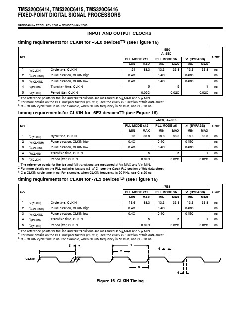
TMS320C6414, TMS320C6415, TMS320C6416FIXED-POINT DIGITAL SIGNAL PROCESSORSSPRS146N − FEBRUARY 2001 − REVISED MAY 2005INPUT AND OUTPUT CLOCKStiming requirements for CLKIN for −5E0 devices †‡§ (see Figure 16)NO −5E0A −5E0NO.PLL MODE x12PLL MODE x6x1 (BYPASS)UNIT MINMAX MIN MAX MIN MAX 1t c(CLKIN)Cycle time, CLKIN 2433.313.333.313.333.3ns 2t w(CLKINH)Pulse duration, CLKIN high 0.4C 0.4C 0.45C ns 3t w(CLKINL)Pulse duration, CLKIN low 0.4C 0.4C 0.45C ns 4t t(CLKIN)Transition time, CLKIN 551ns 5t J(CLKIN)Period jitter, CLKIN 0.02C 0.02C 0.02C ns †The reference points for the rise and fall transitions are measured at V IL MAX and V IH MIN.‡For more details on the PLL multiplier factors (x6, x12), see the Clock PLL section of this data sheet.§C = CLKIN cycle time in ns. For example, when CLKIN frequency is 50 MHz, use C = 20 ns.timing requirements for CLKIN for -6E3 devices †‡§ (see Figure 16)−6E3, A −6E3PLL MODE x12PLL MODE x6x1 (BYPASS)NO.MIN MAX MIN MAX MIN MAX UNIT 1t c(CLKIN)Cycle time, CLKIN 2033.313.333.313.333.3ns 2t w(CLKINH)Pulse duration, CLKIN high 0.4C 0.4C 0.45C ns 3t w(CLKINL)Pulse duration, CLKIN low 0.4C 0.4C 0.45C ns 4t t(CLKIN)Transition time, CLKIN 551ns 5t J(CLKIN)Period jitter, CLKIN 0.02C 0.02C 0.02C ns †The reference points for the rise and fall transitions are measured at V IL MAX and V IH MIN.‡For more details on the PLL multiplier factors (x6, x12), see the Clock PLL section of this data sheet.§C = CLKIN cycle time in ns. For example, when CLKIN frequency is 50 MHz, use C = 20 ns.timing requirements for CLKIN for -7E3 devices †‡§ (see Figure 16)−7E3PLL MODE x12PLL MODE x6x1 (BYPASS)NO.MIN MAX MIN MAX MIN MAX UNIT 1t c(CLKIN)Cycle time, CLKIN 16.633.313.333.313.333.3ns 2t w(CLKINH)Pulse duration, CLKIN high 0.4C 0.4C 0.45C ns 3t w(CLKINL)Pulse duration, CLKIN low 0.4C 0.4C 0.45C ns 4t t(CLKIN)Transition time, CLKIN 551ns 5t J(CLKIN)Period jitter, CLKIN 0.02C 0.02C 0.02C ns †The reference points for the rise and fall transitions are measured at V IL MAX and V IH MIN.‡For more details on the PLL multiplier factors (x6, x12), see the Clock PLL section of this data sheet.§C = CLKIN cycle time in ns. For example, when CLKIN frequency is 50 MHz, use C = 20 ns.CLKINFigure 16. CLKIN TimingTMS320C6414, TMS320C6415, TMS320C6416FIXED-POINT DIGITAL SIGNAL PROCESSORSSPRS146N − FEBRUARY 2001 − REVISED MAY 2005 ASYNCHRONOUS MEMORY TIMING (CONTINUED)timing requirements for asynchronous memory cycles for EMIFB module†‡§(see Figure 22 and Figure 23)NO.−5E0−6E3−7E3A−5E0A−6E3UNIT MIN MAX MIN MAX3t su(EDV-AREH)Setup time, EDx valid before ARE high 6.2 6.2ns 4t h(AREH-EDV)Hold time, EDx valid after ARE high11ns 6t su(ARDY-EKO1H)Setup time, ARDY valid before ECLKOUTx high33nsRev 1.1 andearlier 1.2 1.7ns 7t h(EKO1H-ARDY)Hold time, ARDY valid after ECLKOUTx highRev 2.0 1.3 1.7ns†To ensure data setup time, simply program the strobe width wide enough. ARDY is internally synchronized. The ARDY signal is only recognized two cycles before the end of the programmed strobe time and while ARDY is low, the strobe time is extended cycle-by-cycle. When ARDY is recognized low, the end of the strobe time is two cycles after ARDY is recognized high. T o use ARDY as an asynchronous input, the pulse width of the ARDY signal should be wide enough (e.g., pulse width = 2E) to ensure setup and hold time is met.‡RS = Read setup, RST = Read strobe, RH = Read hold, WS = Write setup, WST = Write strobe, WH = Write hold. These parameters are programmed via the EMIF CE space control registers.§These C64x™ devices have two EMIFs (EMIFA and EMIFB). All EMIFA signals are prefixed by an “A” and all EMIFB signals are prefixed by a “B”. Throughout the rest of this document, in generic EMIF areas of discussion, the prefix “A” or “B” may be omitted [e.g., the asynchronous memory access signals are shown as generic (AOE, ARE, and AWE) instead of AAOE, AARE, and AAWE (for EMIFA) and BAOE, BARE, and BAWE (for EMIFB)].switching characteristics over recommended operating conditions for asynchronous memory cycles for EMIFB module‡§¶# (see Figure 22 and Figure 23)NO.PARAMETER −5E0, A−5E0,−6E3, A−6E3,−7E3UNITMIN MAX1t osu(SELV-AREL)Output setup time, select signals valid to ARE low RS * E − 1.6ns 2t oh(AREH-SELIV)Output hold time, ARE high to select signals invalid RH * E − 1.7ns 5t d(EKO1H-AREV)Delay time, ECLKOUTx high to ARE valid0.8 6.6ns 8t osu(SELV-AWEL)Output setup time, select signals valid to AWE low WS * E − 1.9ns 9t oh(AWEH-SELIV)Output hold time, AWE high to select signals invalid WH * E − 1.7ns 10t d(EKO1H-AWEV)Delay time, ECLKOUTx high to AWE valid0.9 6.7ns RS = Read setup, RST = Read strobe, RH = Read hold, WS = Write setup, WST = Write strobe, WH = Write hold. These parameters are programmed via the EMIF CE space control registers.§These C64x™ devices have two EMIFs (EMIFA and EMIFB). All EMIFA signals are prefixed by an “A” and all EMIFB signals are prefixed by a “B”. Throughout the rest of this document, in generic EMIF areas of discussion, the prefix “A” or “B” may be omitted [e.g., the asynchronous memory access signals are shown as generic (AOE, ARE, and AWE) instead of AAOE, AARE, and AAWE (for EMIFA) and BAOE, BARE, and BAWE (for EMIFB)].¶E = ECLKOUT1 period in ns for EMIFA or EMIFB#Select signals for EMIFA include: ACEx, ABE[7:0], AEA[22:3], AAOE; and for EMIFA writes, include AED[63:0].Select signals EMIFB include: BCEx, BBE[1:0], BEA[20:1], BAOE; and for EMIFB writes, include BED[15:0].。
DSP(TMS320C6713)入门之旅四、edma的理解和使用
DSP(TMS320C6713)入门之旅四、edma的理解和使用EDMA的全称是:Enhanced Direct Memory Access(增强型dma),增强型直接内存存取(EDMA)是数字信号处理器(DSP)中用于快速数据交换的重要技术,具有独立于CPU的后台批量数据传输的能力,能够满足实时图像处理中高速数据传输的要求。
以TI公司的TMS320C6713型DSP为例,介绍EDMA控制器的特点。
结合实例给出EDMA在数据实时传输中的具体控制和实现方法。
实验结果表明,通过灵活控制EDMA不仅能够提高数据的传输效率,而且能够充分发挥:DSP的高速性能。
也就是在我们一般的dma的基础上做了一下加工以完成特定的功能。
比如我们dma传送数据一般是连续的一片数据块,但是我们想间隔着传送就不行了。
还有就是增强型的dma可以实现二维的传送和一个事件可以发起两次传送,这样就可以很好的服务我们的数据传送要求!如图EDMA结构图:可以看到我们配置自己的edma之后,就等待传送事件的到来,当传送事件到来的时候edma的控制器就接受到一个触发信号,就进入传送过程。
传送的规则定义在edma的每一个通道的参数设置里面,我们可以通过控制传送的参数来达到我们要传送的数据的控制的目的!传送参数表如图:第一个双字就是控制edma传送的规则,比如:一维单元同步,一维帧同步,二维等等。
这些控制属性得在这个域里面对其进行说明。
第二个双字就是告诉edma要传送数据的源地址,第三个双字的帧的数目和单元的数目,第四个双字就是告诉edma要传送数据的目的地址。
第五个双字告诉edma下一次触发时地址的偏移量的量。
第六个双字就是当前的单元传送完成之后的单元数目的重载值和是否edma是否需要要链接到下一个edma(注意:这儿是通道链接)我们先来理解几个概念:事件链接:实质就是想一个事件触发之后引起两次edma的搬移,当然这两次搬移不是同一个edma通道,如果是同一个edma通道,相当于同样的数据搬移两次,这样不仅没有意义,还会占用内部总线带宽,印象片内数据的流动的速度。
DSP(TMS320C6713)入门之旅一、LED的点亮
最近很多朋友开始学习DSP了(小双同志也加入这个团伙),本人基本上入门。
在此给他家分享一下DSP的入门经验。
其实DSP和我们本科所使用的单片机基本上架构一致,只是在它的内部集成了一系列的运算单元和逻辑移位单元,并且安排了指令流水,这样在运算性能上大大的提高,可以完成一系列的复杂计算。
当然DSP内部也集成了一系列外设,我这儿使用的是TMS320C6713 DSP,这块DSP主频可以达到450M,可以安排8级指令流水,在同一时刻可以同时执行8条指令,当然这要求的是CPU内部的运算单元不能冲突!好了,在此我就不多介绍了,免得把大家说得晕呼呼的!我们刚才是入门了解这些基本上没用,我们得一步一步的按着简单的东西一步一步的做实验。
所以我们今天开始一个最简单的实验—LED灯的点亮!我们一般学习是要买一块开发板,在此我不做推销,其实每一块开发板都基本上差不多,很多就是按照TI公司的Demo板,而设计的。
如果没有学习板,自己看书看了半年,还不如我拿到板子调试一个月的效果,因为很多东西是要在实际中才知道他的作用。
我们用一个板子一般要几样东西:一、原理图(知道每一根信号线的走向,比如我们的LED就连接到DSP的GPIO的13脚)二、芯片资料(芯片的总的芯片Datasheet和子模块的Datasheet,一般在芯片资料中总的芯片资料会告诉大家芯片的整体规划,比如内存分布,特殊寄存器的分布和具体的地址,而子模块资料会把这个模块的功能和使用介绍得更为详细)三、电路板和仿真器(这个是投入较大的一笔了)四、编译软件和计算机(希望在做实验之前大家用过编译器,不一定是CCS,因为所有基于windows上的编译软件都是一个样)我们来开始第一步,查看我们的电路板上的LED灯的位置和DSP的信号线的连接:从左边的几个原理图的截图我们可以清晰的看到LED灯接到了GPIO的13脚,中间用了一个缓冲器过度了一下,实际的控制信号还是来自DSP的GPIO13。
MEMORY存储芯片TMS320C6713GDP中文规格书
TMS320C6414, TMS320C6415, TMS320C6416FIXED-POINT DIGITAL SIGNAL PROCESSORSSPRS146N − FEBRUARY 2001 − REVISED MAY 2005Terminal Functions (Continued)SIGNALNAMENO.TYPE †IPD/IPU ‡DESCRIPTION RESETS, INTERRUPTS, AND GENERAL-PURPOSE INPUT/OUTPUTS RESETAC7I Device reset NMIB4I IPD Nonmaskable interrupt, edge-driven (rising edge)GP7/EXT_INT7AF4General-purpose input/output (GPIO) pins (I/O/Z GP6/EXT_INT6AD5General purpose input/output (GPIO) pins () or external interrupts (input only ). The default after reset setting is GPIO enabled as input-only.GP5/EXT_INT5AE5I/O/Z IPU •When these pins function as External Interrupts [by selecting the corresponding interrupt GP4/EXT_INT4AF5enable register bit (IER.[7:4])], they are edge-driven and the polarity can be independently selected via the External Interrupt Polarity Register bits (EXTPOL.[3:0]).GP15/PRST §G3General-purpose input/output (GPIO) 15 pin (I/O/Z ) or PCI reset (I ). No function at default.GP14/PCLK §F2GPIO 14 pin (I/O/Z ) or PCI clock (I ). No function at default.GP13/PINTA §G4GPIO 13 pin (I/O/Z ) or PCI interrupt A (O/Z ). No function at default.GP12/PGNT §J3GPIO 12 pin (I/O/Z ) or PCI bus grant (I ). No function at default.GP11/PREQ §F1GPIO 11 pin (I/O/Z ) or PCI bus request (O/Z ). No function at default.GP10/PCBE3§L2GPIO 10 pin (I/O/Z ) or PCI command/byte enable 3 (I/O/Z ). No function at default.GP9/PIDSEL §M3I/O/Z GPIO 9 pin (I/O/Z ) or PCI initialization device select (I ). No function at default.GP3AC6IPD GPIO 3 pin (I/O/Z ). The default after reset setting is GPIO 3 enabled as input-only.GP0AF6IPD GPIO 0 pin.The general-purpose I/O 0 pin (GPIO 0) (I/O/Z ) can be programmed as GPIO 0 (input only )[default] or as GPIO 0 (output only ) pin or output as a general-purpose interrupt (GP0INT)signal (output only ).CLKS2/GP8§¶AE4I/O/Z IPD McBSP2 external clock source (CLKS2) [input only ] [default] or this pin can be pro-grammed as a GPIO 8 pin (I/O/Z ).CLKOUT6/GP2§¶AD6I/O/Z IPD Clock output at 1/6 of the device speed (O/Z ) [default] or this pin can be programmed as aGPIO 2 pin (I/O/Z ).CLKOUT4/GP1§¶AE6I/O/Z IPD Clock output at 1/4 of the device speed (O/Z ) [default] or this pin can be programmed as aGPIO 1 pin (I/O/Z ).HOST-PORT INTERFACE (HPI) [C64x] or PERIPHERAL COMPONENT INTERCONNECT (PCI) [C6415 or C6416 devices only]PCI_EN AA4I IPD PCI enable pin. This pin controls the selection (enable/disable) of the HPI and GP[15:9], orPCI peripherals (for the C6415 and C6416 devices). This pin works in conjunction with theMCBSP2_EN pin to enable/disable other peripherals (for more details, see the Device Con-figurations section of this data sheet).The C6414 device does not support the PCI peripheral; for proper device operation, do notoppose the internal pulldown (IPD) on this pin.HINT/PFRAME §R4I/O/Z Host interrupt from DSP to host (O ) [default] or PCI frame (I/O/Z )HCNTL1/PDEVSEL §R1I/O/Z Host control − selects between control, address, or data registers (I ) [default] or PCI device select (I/O/Z ).HCNTL0/PSTOP §T4I/O/Z Host control − selects between control, address, or data registers (I ) [default] or PCI stop (I/O/Z )HHWIL/PTRDY §R3I/O/Z Host half-word select − first or second half-word (not necessarily high or low order)[For HPI16 bus width selection only] (I ) [default] or PCI target ready (I/O/Z )HR/W/PCBE2§P1I/O/Z Host read or write select (I ) [default] or PCI command/byte enable 2 (I/O/Z )†I = Input, O = Output, Z = High impedance, S = Supply voltage, GND = Ground ‡IPD = Internal pulldown, IPU = Internal pullup. (These IPD/IPU signal pins feature a 30-k Ω IPD or IPU resistor. T o pull up a signal to the opposite supply rail, a 1-k Ω resistor should be used.)§For the C6415 and C6416 devices, these pins are multiplexed pins. For more details, see the Device Configurations section of this data sheet.The C6414 device does not support the PCI or UTOPIA peripherals; therefore, these muxed peripheral pins are standalone peripheral functions for this device.¶For the C6414 device, only these pins are multiplexed pins.TMS320C6414, TMS320C6415, TMS320C6416FIXED-POINT DIGITAL SIGNAL PROCESSORSSPRS146N − FEBRUARY 2001 − REVISED MAY 2005 Terminal Functions (Continued)SIGNAL NAME NO.TYPE†IPD/IPU‡DESCRIPTIONEMIFB (16-bit) − CONTROL SIGNALS COMMON TO ALL TYPES OF MEMORY||kBCE3A13O/Z IPUBCE2C12O/Z IPU EMIFB memory space enablesBCE1B12O/Z IPU•Enabled by bits 26 through 31 of the word address BCE0A12O/Z IPU•Only one pin is asserted during any external data accessBBE1D13O/Z IPU EMIFB byte-enable control•Decoded from the low-order address bits. The number of address bits or byte enables used depends on the width of external memoryBBE0C13O/Z IPUused depends on the width of external memory.•Byte-write enables for most types of memory•Can be directly connected to SDRAM read and write mask signal (SDQM)BPDT E12O/Z IPU EMIFB peripheral data transfer, allows direct transfer between external peripheralsEMIFB (16-BIT) − BUS ARBITRATION||kBHOLDA E13O IPU EMIFB hold-request-acknowledge to the hostBHOLD B19I IPU EMIFB hold request from the hostBBUSREQ E14O IPU EMIFB bus request outputEMIFB (16-BIT) − ASYNCHRONOUS/SYNCHRONOUS MEMORY CONTROL||kBECLKIN A11I IPD EMIFB external input clock. The EMIFB input clock (BECLKIN, CPU/4 clock, or CPU/6 clock) is selected at reset via the pullup/pulldown resistors on the BEA[15:14] pins.BECLKIN is the default for the EMIFB input clock.BECLKOUT2D11O/Z IPD EMIFB output clock 2. Programmable to be EMIFB input clock (BECLKIN, CPU/4 clock, or CPU/6 clock) frequency divided by 1, 2, or 4.BECLKOUT1D12O/Z IPD EMIFB output clock 1 [at EMIFB input clock (BECLKIN, CPU/4 clock, or CPU/6 clock) frequency].BARE/BSDCAS/ BSADS/BSRE A10O/Z IPUEMIFB asynchronous memory read-enable/SDRAM column-address strobe/programmablesynchronous interface-address strobe or read-enable•For programmable synchronous interface, the RENEN field in the CE Space SecondaryControl Register (CExSEC) selects between BSADS and BSRE:If RENEN = 0, then the BSADS/BSRE signal functions as the BSADS signal.If RENEN = 1, then the BSADS/BSRE signal functions as the BSRE signal.BAOE/BSDRAS/ BSOE B11O/Z IPUEMIFB asynchronous memory output-enable/SDRAM row-address strobe/programmablesynchronous interface output-enableBAWE/BSDWE/BSWE C11O/Z IPU EMIFB asynchronous memory write-enable/SDRAM write-enable/programmable synchro-nous interface write-enableBSOE3E15O/Z IPU EMIFB synchronous memory output enable for BCE3 (for glueless FIFO interface) BARDY E11I IPU EMIFB asynchronous memory ready input†I = Input, O = Output, Z = High impedance, S = Supply voltage, GND = Ground‡IPD = Internal pulldown, IPU = Internal pullup. (These IPD/IPU signal pins feature a 30-kΩ IPD or IPU resistor. T o pull up a signal to the opposite supply rail, a 1-kΩ resistor should be used.)||These C64x™ devices have two EMIFs (64-bit EMIFA and 16-bit EMIFB). The prefix “A” in front of a signal name indicates it is an EMIFA signal whereas a prefix “B” in front of a signal name indicates it is an EMIFB signal. Throughout the rest of this document, in generic EMIF areas of discussion, the prefix “A” or “B” may be omitted from the signal name.k To maintain signal integrity for the EMIF signals, serial termination resistors should be inserted into all EMIF output signal lines.。
MEMORY存储芯片TMS320C6713BGDP中文规格书
TMS320C6414, TMS320C6415, TMS320C6416FIXED-POINT DIGITAL SIGNAL PROCESSORSSPRS146N − FEBRUARY 2001 − REVISED MAY 2005peripheral register descriptionsTable 4 through Table 23 identify the peripheral registers for the C6414, C6415, and C6416 devices by their register names, acronyms, and hex address or hex address range. For more detailed information on the register contents, bit names and their descriptions, see the specific peripheral reference guide listed in the TMS320C6000 DSP Peripherals Overview Reference Guide (literature number SPRU190).Table 4. EMIFA RegistersHEX ADDRESS RANGE ACRONYM REGISTER NAME0180 0000GBLCTL EMIFA global control0180 0004CECTL1EMIFA CE1 space control0180 0008CECTL0EMIFA CE0 space control0180 000C−Reserved0180 0010CECTL2EMIFA CE2 space control0180 0014CECTL3EMIFA CE3 space control0180 0018SDCTL EMIFA SDRAM control0180 001C SDTIM EMIFA SDRAM refresh control0180 0020SDEXT EMIFA SDRAM extension0180 0024 − 0180 003C−Reserved0180 0040PDTCTL Peripheral device transfer (PDT) control0180 0044CESEC1EMIFA CE1 space secondary control0180 0048CESEC0EMIFA CE0 space secondary control0180 004C−Reserved0180 0050CESEC2EMIFA CE2 space secondary control0180 0054CESEC3EMIFA CE3 space secondary control0180 0058 − 0183 FFFF–ReservedTable 5. EMIFB RegistersHEX ADDRESS RANGE ACRONYM REGISTER NAME01A8 0000GBLCTL EMIFB global control01A8 0004CECTL1EMIFB CE1 space control01A8 0008CECTL0EMIFB CE0 space control01A8 000C−Reserved01A8 0010CECTL2EMIFB CE2 space control01A8 0014CECTL3EMIFB CE3 space control01A8 0018SDCTL EMIFB SDRAM control01A8 001C SDTIM EMIFB SDRAM refresh control01A8 0020SDEXT EMIFB SDRAM extension01A8 0024 − 01A8 003C−Reserved01A8 0040PDTCTL Peripheral device transfer (PDT) control01A8 0044CESEC1EMIFB CE1 space secondary control01A8 0048CESEC0EMIFB CE0 space secondary control01A8 004C−Reserved01A8 0050CESEC2EMIFB CE2 space secondary control01A8 0054CESEC3EMIFB CE3 space secondary control01A8 0058 − 01AB FFFF–ReservedTMS320C6414, TMS320C6415, TMS320C6416FIXED-POINT DIGITAL SIGNAL PROCESSORSSPRS146N − FEBRUARY 2001 − REVISED MAY 2005 peripheral register descriptions (continued)Table 8. EDMA Parameter RAM†HEX ADDRESS RANGE ACRONYM REGISTER NAME COMMENTS 01A0 0000 − 01A0 0017−Parameters for Event 0 (6 words)01A0 0018 − 01A0 002F−Parameters for Event 1 (6 words)01A0 0030 − 01A0 0047−Parameters for Event 2 (6 words)01A0 0048 − 01A0 005F−Parameters for Event 3 (6 words)01A0 0060 − 01A0 0077−Parameters for Event 4 (6 words)01A0 0078 − 01A0 008F−Parameters for Event 5 (6 words)01A0 0090 − 01A0 00A7−Parameters for Event 6 (6 words)01A0 00A8 − 01A0 00BF−Parameters for Event 7 (6 words)01A0 00C0 − 01A0 00D7−Parameters for Event 8 (6 words)01A0 00D8 − 01A0 00EF−Parameters for Event 9 (6 words)01A0 00F0 − 01A0 00107−Parameters for Event 10 (6 words)01A0 0108 − 01A0 011F−Parameters for Event 11 (6 words)01A0 0120 − 01A0 0137−Parameters for Event 12 (6 words)01A0 0138 − 01A0 014F−Parameters for Event 13 (6 words)01A0 0150 − 01A0 0167−Parameters for Event 14 (6 words)01A0 0168 − 01A0 017F−Parameters for Event 15 (6 words)01A0 0150 − 01A0 0167−Parameters for Event 16 (6 words)01A0 0168 − 01A0 017F−Parameters for Event 17 (6 words)............01A0 05D0 − 01A0 05E7−Parameters for Event 62 (6 words)01A0 05E8 − 01A0 05FF−Parameters for Event 63 (6 words)01A0 0600 − 01A0 0617−Reload/link parameters for Event M (6 words)01A0 0618 − 01A0 062F−Reload/link parameters for Event N (6 words)......01A0 07E0 − 01A0 07F7−Reload/link parameters for Event Z (6 words)01A0 07F8 − 01A0 07FF−Scratch pad area (2 words)†The C6414/C6415/C6416 device has twenty-one parameter sets [six (6) words each] that can be used to reload/link EDMA transfers.Table 9. Quick DMA (QDMA) and Pseudo RegistersHEX ADDRESS RANGE ACRONYM REGISTER NAME0200 0000QOPT QDMA options parameter register0200 0004QSRC QDMA source address register0200 0008QCNT QDMA frame count register0200 000C QDST QDMA destination address register0200 0010QIDX QDMA index register0200 0014 − 0200 001C Reserved0200 0020QSOPT QDMA pseudo options register0200 0024QSSRC QDMA pseudo source address register0200 0028QSCNT QDMA pseudo frame count register0200 002C QSDST QDMA pseudo destination address register0200 0030QSIDX QDMA pseudo index register。
MEMORY存储芯片TMS32C6713BZDPA200中文规格书
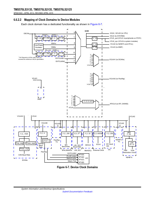
TMS570LS3135, TMS570LS2135, TMS570LS2125SPNS164C – APRIL 2012 – REVISED APRIL 20156.6.2.2 Mapping of Clock Domains to Device Modules Each clock domain has a dedicated functionality as shown in Figure 6-7.OSCIN0FMzPLL (SSPLL)/1..64 X1..256 /1..8/1..32 *180kHz4Low PowerOscillator10MHz5PLL # 2 (SSPLL)/1..64 X1..256 /1..8/1..32 *6* the frequency at this node must not exceed the maximum HCLK specifiation.3 EXTCLKIN 1EXTCLKIN27GCM/1..16/1..16 /1..160 1 3 4 5 6 7 VCLKGCLK, GCLK2 (to CPU) HCLK (to SYSTEM) VCLK _peri (VCLK to peripherals on PCR1) VCLK_sys (VCLK to system modules) VCLK2 (to N2HETx and HTUx) VCLK3 (to EMIF)VCLKA1 (to DCANx)VCLK30 1 345 67 VCLKVCLKA2 (to FlexRay)VCLKA1EMIFVCLK VCLKA2VCLKA20 1 3 4 5 6 7VCLK/1, 2, 4, or 8RTICLK (to RTI, DWWD)VCLK2VCLK2/1,2,..1024/1,2,..4/1,2,..256/2,3..224/1,2..32 /1,2..65536/1,2..256HRP /1..64Prop_seg Phase_seg2 Phase_seg1CAN Baud RateGTUC1,2 FlexRayBaud RateFlexRayDCANxFlexRay TUSPI Baud RateLIN / SCI Baud RateADCLKECLKSPIx,MibSPIx LIN, SCI MibADCxEXTCLKIN1 PLL#2 output Start of cycleMacro TickNTU[3] NTU[2]RTI NTU[1] NTU[0]External ClockI2C baud rateI2CN2HETx TULRP /20..25High Loop Resolution ClockN2HETxFigure 6-7. Device Clock DomainsSystem Information and Electrical Specifications Submit Documentation FeedbackTMS570LS3135, TMS570LS2135, TMS570LS2125SPNS164C – APRIL 2012 – REVISED APRIL 20156.6.3 Clock Test ModeThe TMS570 platform architecture defines a special mode that allows various clock signals to be brought out on to the ECLK pin and N2HET1[12] device outputs. This mode is called the Clock Test mode. It is very useful for debugging purposes and can be configured via the CLKTEST register in the system module.SEL_ECP_PIN =CLKTEST[3-0] 0000 0001 0010 0011 0100 0101 0110 0111 1000 1001 1010 1011 1100 1101 1110 1111Table 6-14. Clock Test Mode OptionsSIGNAL ON ECLKOscillator Main PLL free-running clock outputReserved EXTCLKIN1CLK80K CLK10M Secondary PLL free-running clock output EXTCLKIN2GCLK RTI Base Reserved VCLKA1 VCLKA2 Reserved VCLKA4 ReservedSEL_GIO_PIN =CLKTEST[11-8] 0000 0001 0010 0011 0100 0101 0110 0111 1000 1001 1010 1011 1100 1101 1110 1111SIGNAL ON N2HET1[12]Oscillator Valid Status Main PLL Valid statusReserved Reserved Reserved CLK10M Valid status Secondary PLL Valid Status Reserved CLK80K Reserved Reserved Reserved Reserved Reserved Reserved ReservedSystem Information and Electrical Specifications Submit Documentation FeedbackTMS570LS3135, TMS570LS2135, TMS570LS2125SPNS164C – APRIL 2012 – REVISED APRIL 20156.7 Clock MonitoringThe LPO Clock Detect (LPOCLKDET) module consists of a clock monitor (CLKDET) and an internal low power oscillator (LPO).The LPO provides two different clock sources – a low frequency (LFLPO) and a high frequency (HFLPO).The CLKDET is a supervisor circuit for an externally supplied clock signal (OSCIN). In case the OSCIN frequency falls out of a frequency window, the CLKDET flags this condition in the global status register (GLBSTAT bit 0: OSC FAIL) and switches all clock domains sourced by OSCIN to the HFLPO clock (limp mode clock).The valid OSCIN frequency range is defined as: fHFLPO / 4 < fOSCIN < fHFLPO * 4.6.7.1 Clock Monitor TimingsFor more information on LPO and Clock detection, refer to Table 6-10.faillowerthresholdpassupper thresholdfail1.375 4.8752278Figure 6-8. LPO and Clock Detection, Untrimmed HFLPOf[MHz]6.7.2 External Clock (ECLK) Output FunctionalityThe ECLK pin can be configured to output a prescaled clock signal indicative of an internal device clock. This output can be externally monitored as a safety diagnostic.6.7.3 Dual Clock ComparatorsThe Dual Clock Comparator (DCC) module determines the accuracy of selectable clock sources by counting the pulses of two independent clock sources (counter 0 and counter 1). If one clock is out of spec, an error signal is generated. For example, the DCC1 can be configured to use CLK10M as the reference clock (for counter 0) and VCLK as the "clock under test" (for counter 1). This configuration allows the DCC1 to monitor the PLL output clock when VCLK is using the PLL output as its source.An additional use of this module is to measure the frequency of a selectable clock source, using the input clock as a reference, by counting the pulses of two independent clock sources. Counter 0 generates a fixed-width counting window after a preprogrammed number of pulses. Counter 1 generates a fixed-width pulse (1 cycle) after a preprogrammed number of pulses. This pulse sets as an error signal if counter 1 does not reach 0 within the counting window generated by counter 0.6.7.3.1 • • • •FeaturesTakes two different clock sources as input to two independent counter blocks. One of the clock sources is the known-good, or reference clock; the second clock source is the "clock under test." Each counter block is programmable with initial, or seed values. The counter blocks start counting down from their seed values at the same time; a mismatch from the expected frequency for the clock under test generates an error signal which is used to interrupt the CPU.System Information and Electrical Specifications Submit Documentation Feedback。
MEMORY存储芯片TMS32C6713BGDPA200中文规格书
TMS570LS3135,TMS570LS2135,TMS570LS2125SPNS164C–APRIL2012–REVISED APRIL2015 TMS570LS31x5/21x516-and32-Bit RISC Flash Microcontroller1Device Overview1.1Features•High-Performance Automotive-Grade•Multiple Communication Interfaces Microcontroller for Safety-Critical Applications–FlexRay Controller With Two Channels–Dual CPUs Running in Lockstep•8KB of Message RAM With Parity Protection –ECC on Flash and RAM Interfaces•Dedicated Transfer Unit(FTU)–Built-In Self-Test(BIST)for CPU and On-chip–Three CAN Controllers(DCANs) RAMs•64Mailboxes,Each With Parity Protection –Error Signaling Module With Error Pin•Compliant to CAN Protocol Version2.0B –Voltage and Clock Monitoring–Standard Serial Communication Interface(SCI)•ARM®Cortex®-R4F32-Bit RISC CPU–Local Interconnect Network(LIN)Interface –Efficient1.66DMIPS/MHz With8-Stage Pipeline Controller–FPU With Single-and Double-Precision•Compliant to LIN Protocol Version2.1–12-Region Memory Protection Unit(MPU)•Can be Configured as a Second SCI –Open Architecture With Third-Party Support–Inter-Integrated Circuit(I2C)•Operating Conditions–Three Multibuffered Serial Peripheral Interfaces –System Clock up to180MHz(MibSPIs)–Core Supply Voltage(VCC):1.2V Nominal•128Words With Parity Protection Each –I/O Supply Voltage(VCCIO):3.3V Nominal–Two Standard Serial Peripheral Interfaces(SPIs)–ADC Supply Voltage(V CCAD):3.0to5.25V•Two Next Generation High-End Timer(N2HET)•Integrated MemoryModules–3MB of Program Flash With ECC(LS3135)–N2HET1:32Programmable Channels –2MB of Program Flash With ECC–N2HET2:18Programmable Channels (LS2135/2125)–160-Word Instruction RAM Each With Parity –256KB of RAM With ECC(LS3135/2135)Protection–192KB of RAM With ECC(LS2125)–Each N2HET Includes Hardware Angle –64KB of Flash With ECC for EmulatedGeneratorEEPROM–Dedicated High-End Transfer Unit(HTU)With •16-Bit External Memory InterfaceMPU for Each N2HET•Common Platform Architecture•Two12-Bit Multibuffered ADC Modules –Consistent Memory Map Across Family–ADC1:24Channels–Real-Time Interrupt(RTI)Timer OS Timer–ADC2:16Channels Shared With ADC1–96-Channel Vectored Interrupt Module(VIM)–64Result Buffers With Parity Protection Each –2-Channel Cyclic Redundancy Checker(CRC)•General-Purpose Input/Output(GPIO)Pins •Direct Memory Access(DMA)ControllerCapable of Generating Interrupts –16Channels and32Control Packets–Sixteen Pins on the ZWT Package –Parity Protection for Control Packet RAM–Four Pins on the PGE Package –DMA Accesses Protected by Dedicated MPU•IEEE1149.1JTAG,Boundary Scan and ARM •Frequency-Modulated Phase-Locked Loop CoreSight™Components (FMPLL)With Built-In Slip Detector•JTAG Security Module•Separate Nonmodulating PLL for FlexRay™•Packages•Trace and Calibration Capabilities–144-Pin Quad Flatpack(PGE)[Green]–Embedded Trace Macrocell(ETM-R4)–337-Ball Grid Array(ZWT)[Green]–Data Modification Module(DMM)–RAM Trace Port(RTP)–Parameter Overlay Module(POM)TMS570LS3135,TMS570LS2135,TMS570LS2125SPNS164C–APRIL2012–REVISED APRIL20151.3DescriptionThe TMS570LS31x5/21x5device is a high-performance automotive-grade microcontroller family for safety systems.The safety architecture includes dual CPUs in lockstep,CPU and memory BIST logic,ECC on both the flash and the data SRAM,parity on peripheral memories,and loopback capability on peripheral I/Os.The TMS570LS31x5/21x5device integrates the ARM Cortex-R4F Floating-Point CPU.The CPU offers an efficient1.66DMIPS/MHz,and has configurations that can run up to180MHz,providing up to298 DMIPS.The device supports the word-invariant big-endian[BE32]format.The TMS570LS3135device has3MB of integrated flash and256KB of data RAM.The TMS570LS2135 device has2MB of integrated flash and256KB of data RAM.The TMS570LS2125device has2MB of integrated flash and192KB of data RAM.Both the flash and RAM have single-bit error correction and double-bit error detection.The flash memory on this device is a nonvolatile,electrically erasable,and programmable memory implemented with a64-bit-wide data bus interface.The flash operates on a3.3-V supply input(same level as I/O supply)for all read,program,and erase operations.When in pipeline mode,the flash operates with a system clock frequency of up to180MHz.The SRAM supports single-cycle read and write accesses in byte,halfword,word,and double-word modes.The TMS570LS31x5/21x5device features peripherals for real-time control-based applications,including two Next Generation High-End Timer(N2HET)timing coprocessors and two12-bit Analog-to-Digital Converters(ADCs)supporting up to24inputs.The N2HET is an advanced intelligent timer that provides sophisticated timing functions for real-time applications.The timer is software-controlled,using a reduced instruction set,with a specialized timer micromachine and an attached I/O port.The N2HET can be used for pulse-width-modulated outputs, capture or compare inputs,or GPIO.The N2HET is especially well suited for applications requiring multiple sensor information and drive actuators with complex and accurate time pulses.A High-End Timer Transfer Unit(HTU)can perform DMA-type transactions to transfer N2HET data to or from main memory.A Memory Protection Unit(MPU)is built into the HTU.The device has two12-bit-resolution MibADCs with24channels and64words of parity-protected buffer RAM each.The MibADC channels can be converted individually or can be grouped by software for sequential conversion sequences.Sixteen channels are shared between the two MibADCs.There are three separate groupings.Each sequence can be converted once when triggered or configured for continuous conversion mode.The MibADC has a10-bit mode for use when compatibility with older devices or faster conversion time is desired.The device has multiple communication interfaces:three MibSPIs,two SPIs,one LIN,one SCI,three DCANs,one I2C module,and one FlexRay controller.The SPIs provide a convenient method of serial high-speed communication between similar shift-register type devices.The LIN supports the Local Interconnect standard2.0and can be used as a UART in full-duplex mode using the standard Non-Return-to-Zero(NRZ)format.The DCAN supports the CAN 2.0(A and B)protocol standard and uses a serial,multimaster communication protocol that efficiently supports distributed real-time control with robust communication rates of up to1Mbps.The DCAN is ideal for systems operating in noisy and harsh environments(for example,automotive vehicle networking and industrial fieldbus)that require reliable serial communication or multiplexed wiring.The FlexRay controller uses a dual-channel serial,fixed time base multimaster communication protocol with communication rates of10Mbps per channel.A FlexRay Transfer Unit(FTU)enables autonomous transfers of FlexRay data to and from the CPU main memory.Transfers are protected by a dedicated, built-in MPU.The I2C module is a multimaster communication module providing an interface between the microcontroller and an I2C-compatible device through the I2C serial bus.The I2C supports speeds of100 and400Kbps.Device OverviewSubmit Documentation FeedbackTMS570LS3135,TMS570LS2135,TMS570LS2125SPNS164C–APRIL2012–REVISED APRIL2015The Frequency-Modulated Phase-Locked Loop(FMPLL)clock module is used to multiply the external frequency reference to a higher frequency for internal use.There are two FMPLL modules on this device.These modules,when enabled,provide two of the seven possible clock source inputs to the Global Clock Module(GCM).The GCM manages the mapping between the available clock sources and the device clock domains.The device also has an External Clock Prescaler(ECP)module that when enabled,outputs a continuous external clock on the ECLK pin(or ball).The ECLK frequency is a user-programmable ratio of the peripheral interface clock(VCLK)frequency.This low-frequency output can be monitored externally as an indicator of the device operating frequency.The DMA controller has16channels,32control packets,and parity protection on its memory.An MPU is built into the DMA to limit the DMA to prescribed areas of memory and to protect the rest of the memory system from any malfunction of the DMA.The Error Signaling Module(ESM)monitors all device errors and determines whether an interrupt is generated or the external ERROR pin is toggled when a fault is detected.The ERROR pin can be monitored externally as an indicator of a fault condition in the microcontroller.The External Memory Interface(EMIF)provides off-chip expansion capability with the ability to interface to synchronous DRAM(SDRAM)devices,asynchronous memories,peripherals or FPGA devices.Several interfaces are implemented to enhance the debugging capabilities of application code.In addition to the built-in ARM Cortex-R4F CoreSight debug features,an External Trace Macrocell(ETM)provides instruction and data trace of program execution.For instrumentation purposes,a RAM Trace Port(RTP) module is implemented to support high-speed tracing of RAM and peripheral accesses by the CPU or any other master.A Data Modification Module(DMM)gives the ability to write external data into the device memory.Both the RTP and DMM have no or only minimum impact on the program execution time of the application code.A Parameter Overlay Module(POM)can reroute flash accesses to internal memory or to the EMIF.This rerouting allows the dynamic calibration against production code of parameters and tables without rebuilding the code to explicitly access RAM or halting the processor to reprogram the data flash.With integrated safety features and a wide choice of communication and control peripherals,the TMS570LS31x5/21x5device is an ideal solution for high-performance real-time control applications with safety-critical requirements.Device Information(1)PART NUMBER PACKAGE BODY SIZETMS570LS2125ZWT NFBGA(337)16.0mm×16.0mmTMS570LS2125PGE LQFP(144)20.0mm×20.0mmTMS570LS2135ZWT NFBGA(337)16.0mm×16.0mmTMS570LS2135PGE LQFP(144)20.0mm×20.0mmTMS570LS3135ZWT NFBGA(337)16.0mm×16.0mmTMS570LS3135PGE LQFP(144)20.0mm×20.0mm(1)For more information,see Section9,Mechanical Packaging and Orderable Information.Device OverviewSubmit Documentation Feedback。
MEMORY存储芯片TMS320C6713BPYP-200中文规格书
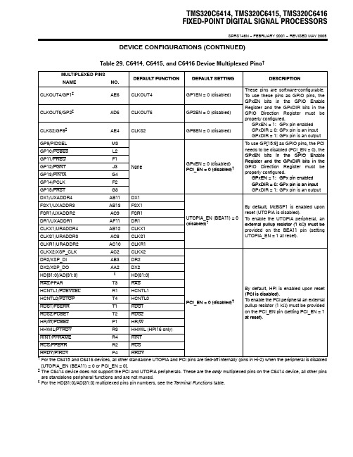
TMS320C6414, TMS320C6415, TMS320C6416FIXED-POINT DIGITAL SIGNAL PROCESSORSSPRS146N − FEBRUARY 2001 − REVISED MAY 2005DEVICE CONFIGURATIONS (CONTINUED)Table 29. C6414, C6415, and C6416 Device Multiplexed Pins †MULTIPLEXED PINSNAMENO.DEFAULT FUNCTION DEFAULT SETTING DESCRIPTION CLKOUT4/GP1‡AE6CLKOUT4GP1EN = 0 (disabled)These pins are software-configurable.To use these pins as GPIO pins, theCLKOUT6/GP2‡AD6CLKOUT6GP2EN = 0 (disabled)GPxEN bits in the GPIO EnableRegister and the GPxDIR bits in theGPIO Direction Register must beCLKS2/GP8‡AE4CLKS2GP8EN = 0 (disabled)properly configured.GPxEN = 1:GPx pin enabledGPxDIR = 0:GPx pin is an inputGPxDIR = 1:GPx pin is an outputGP9/PIDSEL M3To use GP[15:9] as GPIO pins, the PCIGP10/PCBE3L2needs to be disabled (PCI_EN = 0), theGP11/PREQ F1GP EN 0 (di bl d)GPxEN bits in the GPIO EnableGP12/PGNT J3GPxEN = 0 (disabled)PCI EN = 0 (disabled)Register and the GPxDIR bits in theGP13/PINTA G4None PCI_EN = 0 (disabled)†GPIO Direction Register must beproperly configured.GPxEN 1:GP14/PCLK F2GPxEN = 1:GPx pin enabled GP15/PRSTG3GPxDIR = 0:GPx pin is an inputGPxDIR = 1:GPx pin is an output DX1/UXADDR4AB11DX1FSX1/UXADDR3AB13FSX1FSR1/UXADDR2AC9FSR1UTOPIA EN (BEA11) 0By default, McBSP1 is enabled upon reset (UTOPIA is disabled).T bl h UTOPIA i h l DR1/UXADDR1AF11DR1UTOPIA_EN (BEA11) = 0()To enable the UTOPIA peripheral, an Ω) must be CLKX1/URADDR4AB12CLKX1(disabled)†external pullup resistor (1 k provided on the BEA11 pin (setting CLKS1/URADDR3AC8CLKS1provided on the BEA11 pin (setting UTOPIA_EN = 1 at reset).CLKR1/URADDR2AC10CLKR1_)CLKX2/XSP_CLKAC2CLKX2DR2/XSP_DIAB3DR2DX2/XSP_DOAA2DX2HD[31:0]/AD[31:0]§HD[31:0]HAS/PPART3HAS HCNTL1/PDEVSELR1HCNTL1By default, HPI is enabled upon reset (PCI is disabled)HCNTL0/PSTOPT4HCNTL0PCI EN 0 (disabled)(PCI is disabled). HDS1/PSERRT1HDS1PCI_EN = 0 (disabled)†To enable the PCI peripheral an external pullup resistor (1 k Ω) must be provided h PCI EN i (i PCI EN 1HDS2/PCBE1T2HDS2p p ()p on the PCI_EN pin (setting PCI_EN = 1at reset)HR/W/PCBE2P1HR/W at reset).HHWIL/PTRDYR3HHWIL (HPI16 only)HINT/PFRAMER4HINT HCS/PPERRR2HCS HRDY/PIRDYP4HRDY †For the C6415 and C6416 devices, all other standalone UTOPIA and PCI pins are tied-off internally (pins in Hi-Z) when the peripheral is disabled[UTOPIA_EN (BEA11) = 0 or PCI_EN = 0].‡The C6414 device does not support the PCI and UTOPIA peripherals. These are the only multiplexed pins on the C6414 device, all other pins are standalone peripheral functions and are not muxed.§For the HD[31:0]/AD[31:0] multiplexed pins pin numbers, see the Terminal Functions table.TMS320C6414, TMS320C6415, TMS320C6416FIXED-POINT DIGITAL SIGNAL PROCESSORSSPRS146N − FEBRUARY 2001 − REVISED MAY 2005 Terminal Functions (Continued)SIGNAL NAME NO.TYPE†IPD/IPU‡DESCRIPTIONEMIFB (16-bit) − DATA||kBED15D7BED14B6BED13C7BED12A6BED11D8BED10B7BED9C8BED8A7BED7C9I/O/Z IPU EMIFB external dataBED6B8BED5D9BED4B9BED3C10BED2A9BED1D10BED0B10MULTICHANNEL BUFFERED SERIAL PORT 2 (McBSP2)MCBSP2_EN AF3I IPD McBSP2 enable pin. This pin works in conjunction with the PCI_EN pin to enable/disable other peripherals (for more details, see the Device Configurations section of this data sheet).CLKS2/GP8§AE4I/O/Z IPD McBSP2 external clock source (CLKS2) [input only] [default] or this pin can also be programmed as a GPIO 8 pin (I/O/Z).CLKR2AB1I/O/Z IPD McBSP2 receive clock. When McBSP2 is disabled (PCI_EN = 1 and MCBSP2_EN pin = 0), this pin is tied-off.CLKX2/XSP_CLK§AC2I/O/Z IPD McBSP2 transmit clock (I/O/Z) [default] or PCI serial interface clock (O).DR2/XSP_DI§AB3I IPU McBSP2 receive data (I) [default] or PCI serial interface data in (I). In PCI mode, this pin is connected to the output data pin of the serial PROM.DX2/XSP_DO§AA2O/Z IPU McBSP2 transmit data (O/Z) [default] or PCI serial interface data out (O). In PCI mode, this pin is connected to the input data pin of the serial PROM.FSR2AC1I/O/Z IPD McBSP2 receive frame sync. When McBSP2 is disabled (PCI_EN = 1 and MCBSP2_EN pin = 0), this pin is tied-off.FSX2AB2I/O/Z IPD McBSP2 transmit frame sync. When McBSP2 is disabled (PCI_EN = 1 and MCBSP2_EN pin = 0), this pin is tied-off.†I = Input, O = Output, Z = High impedance, S = Supply voltage, GND = Ground‡IPD = Internal pulldown, IPU = Internal pullup. (These IPD/IPU signal pins feature a 30-kΩ IPD or IPU resistor. T o pull up a signal to the opposite supply rail, a 1-kΩ resistor should be used.)§For the C6415 and C6416 devices, these pins are multiplexed pins. For more details, see the Device Configurations section of this data sheet. The C6414 device does not support the PCI or UTOPIA peripherals; therefore, these muxed peripheral pins except CLKS2/GP8 are standalone peripheral functions for this device.||These C64x™ devices have two EMIFs (64-bit EMIFA and 16-bit EMIFB). The prefix “A” in front of a signal name indicates it is an EMIFA signal whereas a prefix “B” in front of a signal name indicates it is an EMIFB signal. Throughout the rest of this document, in generic EMIF areas of discussion, the prefix “A” or “B” may be omitted from the signal name.k To maintain signal integrity for the EMIF signals, serial termination resistors should be inserted into all EMIF output signal lines.。
ICETEK-C6713-A 硬件使用说明书
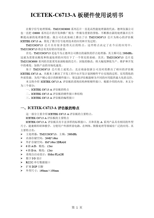
(11). J4,J5:D/A 功能选择跳线,进行 7616、7617 芯片选择。(由厂家跳线) (12). J7:4 个用户开关输入。可以用作 DSP 的输入信号。软件可以读取它的状
AGND 模拟地
第5页
(5). P3:34 芯扩展总线接口。
表 2.5 P3 的管脚定义和说明:
管脚号 管脚名
说明
1
A2 C6713 地址线 A2
2
A3 C6713 地址线 A3
3
A4 C6713 地址线 A4
4
A5 C6713 地址线 A5
5
A6 C6713 地址线 A6
6
A7 C6713 地址线 A7
表 2.2 P6 管脚定义表
管脚定义
说明
NC TxD1 RxD2 NC GND NC RxD2
无连接 数据输出引脚 1,与对方的输入脚连接 数据输入引脚 1,与对方的输出脚连接
无连接 共地端 无连接 数据输出引脚 2,与对方的输入脚连接
第3页
8
TxD2
数据输入引脚 2,与对方的输出脚连接
9
Vcc
VCC
表32存储器映射图内存块描述内存块大小字节16进制地址范围内部raml2192k000000000002ffff内部ramcatch64k000300000003ffff保留24m256k00040000017fffff外部存储器接口emif寄存256k018000000183ffffl2寄存器128k018400000185ffff保留128k018600000187ffffhpi寄存器256k01880000018bffffmcbsp寄存器256k018c0000018fffffmcbsp寄存器256k019000000193ffff定时器寄存器256k019400000197ffff定时器寄存器256k01980000019bffff中断选择寄存器512019c0000019c01ff芯片配置寄存器019c0200019c0203保留256k516019c0204019fffffedmaramedma寄存256k01a0000001a3ffff保留768k01a4000001afffffgpio寄存器16k01b0000001b03fff保留240k01b0400001b3ffffi2c0寄存器16k01b4000001b43fffi2c1寄存器16k01b4400001b47fff保留16k01b4800001b4bfffmcasp0寄存器16k01b4c00001b4ffffmcasp1寄存器16k01b5000001b53fff保留160k01b5400001b7bfffpll寄存器8k01b7c00001b7dfff保留264k01b7e00001bbffffemulation寄存器256k01bc000001bfffff保留4m01c0000001ffffffqdma寄存器520200000002000033保留16m520200003402ffffff保留720m030000002fffffffmcbsp0数据口64m3000000033ffffffmcbsp1数据口64m3400000037ffffff保留64m380000003bffffffmcasp0数据口1m3c0000003c0fffffmcasp1数据口1m3c1000003c1fffff保留1g62m3c2000007fffffff片外扩展sdram16m8000000080fffffffemifce0?保留240m8100000
TMS320C6713的FLASH引导装载系统设计

在TMS320C6713板中,为了使SDRAM,FLASH运行起来,需要设置寄存器,同时同步时钟需要进行PLL 的设置。
基本寄存器构型:/* EMIF setup */*(int *)EMIF_GCTL = 0x00000068;*(int *)EMIF_CE0 = 0x20f20333; /* CE0 SDRAM */*(int *)EMIF_CE1 = 0xffffff23; /* CE1 Flash */*(int *)EMIF_CE2 = 0x20f20323; /* CE2 I/O 32-bit async */*(int *)EMIF_CE3 = 0xffffff23; /* CE3 I/O 32-bit async */*(int *)EMIF_SDRAMCTL = 0x53116000; /* SDRAM control (32 Mb) */*(int *)EMIF_SDRAMTIM = 0x00000578; /* SDRAM timing (refresh) */*(int *)EMIF_SDRAMEXT = 0x000a8529; /* SDRAM Extension register */PLL寄存器构型:/* Set the PLL back to power on reset state*/*(int *)PLL_CSR = 0x00000048;*(int *)PLL_DIV3 = 0x00008001;*(int *)PLL_DIV2 = 0x00008001;*(int *)PLL_DIV1 = 0x00008000;*(int *)PLL_DIV0 = 0x00008000;*(int *)PLL_MULT = 0x00000007;*(int *)PLL_OSCDIV1 = 0x00008007;2 TMS320C6713 DSP板的Loader过程和以往TI公司的DSP(如3x,4x)采用引导表由固化在DSP内部的引导程序实现程序的自引导不同,TMS320C6000系列DSP采用的是一种新的引导方法,对于TMS320C6713,上电后,若选择从EMIF引导程序,则DSP自动将位于地址空间CE1(0x90000000~0x9FFFFFFF)开头的1KB代码传输到地址空间0处。
TMS320C6713 DSP的SPI接口设计
MCBSP_FMKS(RCR, RDATDLY, 1BIT)
|
为从:必须为 0bit
MCBSP_FMKS(RCR, RFRLEN1, OF(0))
|
此位必须为 0
MCBSP_FMKS(RCR, RWDLEN1, 8BIT)
|
MCBSP_FMKS(RCR, RWDREVRS, DEFAULT),
/* Transmit Control Register (XCR) */
当 DSP 作为主设备时,串行时钟 CLKX0 由 DSP 内部的采样率发生器(SRG)提供,其速 率与极性需要经过寄存器配置;从设备使能信号 FSX0 也由 DSP 提供,由其内部的采样率发 生器产生。
SPI 的串行通信属于“数据交换”类型的数据通信,其数据的交换是由主设备发起的。 当 DSP 需要发送数据给 ARM 芯片时,由 DSP 向发送管脚 DX0 中写入数据,DSP 就会产生串行 时钟 CLKX0 与从设备使能信号 FSX0。当从设备的 SPICLK0 检测到时钟信号,同时 nSS0 检测 到 FSX0 的低电平信号时,从设备就从 SPIMOSI0 中接收数据,同时将 SPIMISO0 中的数据发 送个 DSP。这里 DSP 的收发数据是同时进行的,DSP 在发送出一个数据的同时也要接收到一 个数据,如果接收到的数据对 DSP 来说是无用数据,读取数据后不做处理即可。
MCBSP_FMKS(XCR, XPHASE, SINGLE)
|
此位必须为 0(SINGLE)
MCBSP_FMKS(XCR, XFRLEN2, DEFAULT)
|
MCBSP_FMKS(XCR, XWDLEN2, DEFAULT)
|
MCBSP_FMKS(XCR, XCOMPAND, DEFAULT)
