CR8PM-12中文资料
RI-12资料
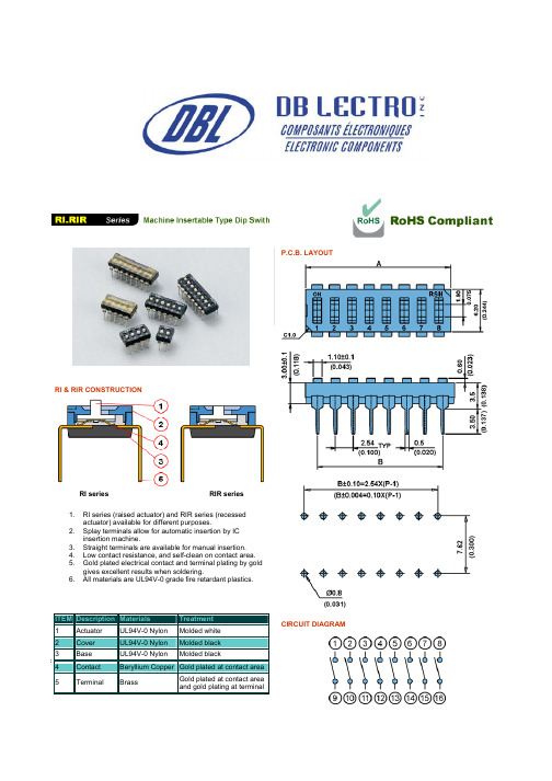
RI & RIR CONSTRUCTIONRI series RIR series1. RI series (raised actuator) and RIR series (recessedactuator) available for different purposes.2. Splay terminals allow for automatic insertion by ICinsertion machine.3. Straight terminals are available for manual insertion.4. Low contact resistance, and self-clean on contact area.5. Gold plated electrical contact and terminal plating by goldgives excellent results when soldering.6. All materials are UL94V-0 grade fire retardant plastics.ITEMDescription Materials Treatment1 Actuator UL94V-0 Nylon Molded white2 Cover UL94V-0 Nylon Molded black3 Base UL94V-0 Nylon Molded black P.C.B. LAYOUT CIRCUIT DIAGRAM4 Contact Beryllium Copper Gold plated at contact area5 Terminal Brass Gold plated at contact area and gold plating at terminalMODELPROD NO. NO. OF POS DIM ARI/RIR-01 01 3.480.137 RI/RIR-02 02 6.02 0.237 RI/RIR-03 03 8.56 0.337 RI/RIR-04 04 11.1 0.437 RI/RIR-05 05 13.64 0.537 RI/RIR-06 06 16.18 0.637 RI/RIR-07 07 18.72 0.737 RI/RIR-08 08 21.26 0.837 RI/RIR-09 09 23.8 0.937 RI/RIR-10 10 26.34 1.037 RI/RIR-12 1231.421.237HOW TO ORDERTERMINAL TYPESPECIFICATIONELECTRICALElectrical life: 2000 operation cycles per switch 24VDC, 25mA.Non-Switching Rating: 100mA, 50 VDC Switching Rating: 25mA, 24VCD.Contact resistance: (a) 50m Ω max. at initial(b) 100m Ω max. after life test.Insulation resistance: 100M Ω min. (at 500VDC) Dielectric Strength: 500VAC/1 minute. Capacitance: 5pF max.Circuit: Single pole single throwMECHANICAL Mechanical life: 2000 operations per cycle switch Operation Force: 600gf max. Stroke: 0.9mmOperation Temp: -25° C to +70° C Storage Temp: -40° C to +85° CVibration Test: MIL-STD-202F METHOD 201AFrequency: 10-55-10Hz/1 min Directions: X, Y, Z, three mutually perpendicular directions.Time: 2 hours each direction. High reliability.Shock Test: MIL-STD-202F METHOD 213B.CONDITION AGRAVITY: 50G (peak value), 11 m/sec.Direction and times: 6 sides and three times in each direction. High reliability.SOLDERING AND CLEANING PROCESSESFor best results, please follow these recommendations: Keep all switch contacts in their "OFF" position for all operations.WAVE SOLDERING: Recommended solder temperature at 500 F (260° C) max. 5 seconds. HANDSOLDERING: Use a soldering iron of 30 watts, controlled at608 F(320° C) approximately 2 seconds while applying solder.CLEANING PROCESS: Flux clean using force rinse, high agitationor triple bath cleaning method. Freon TF or TE give excellent results. When vapor methods are used, do not subject the switch to solvents at temperatures above 125 F (51° C).Example: RI-08G-S is a Machine Insertable Type Dip Switch,Raised Actuator 8 position, splay terminal.PACKING All DIP switches are shipped in standard IC tubes withall poles in "OFF" position.。
LM78M12中文资料

LM78M12中⽂资料LM341/LM78MXX Series3-Terminal Positive Voltage RegulatorsGeneral DescriptionThe LM341and LM78MXX series of three-terminal positive voltage regulators employ built-in current limiting,thermal shutdown,and safe-operating area protection which makes them virtually immune to damage from output overloads.With adequate heatsinking,they can deliver in excess of 0.5A output current.Typical applications would include local (on-card)regulators which can eliminate the noise and de-graded performance associated with single-point regulation.Featuresn Output current in excess of 0.5A n No external componentsn Internal thermal overload protection n Internal short circuit current-limitingn Output transistor safe-area compensationnAvailable in TO-220,TO-39,and TO-252D-PAK packagesn Output voltages of 5V,12V,and 15VConnection DiagramsTO-39Metal Can Package (H)DS010484-5Bottom ViewOrder Number LM78M05CH,LM78M12CH or LM78M15CHSee NS Package Number H03ATO-220Power Package (T)DS010484-6Top ViewOrder Number LM341T-5.0,LM341T-12,LM341T-15,LM78M05CT,LM78M12CT or LM78M15CTSee NS Package Number T03BTO-252DS010484-19Top ViewOrder Number LM78M05CDT See NS Package Number TD03BJuly 1999LM341/LM78MXX Series 3-Terminal Positive Voltage Regulators1999National Semiconductor Corporation /doc/96ef4d46852458fb770b5641.htmlAbsolute Maximum Ratings(Note1)If Military/Aerospace specified devices are required, please contact the National Semiconductor Sales Office/ Distributors for availability and specifications.Lead Temperature(Soldering,10seconds)TO-39Package(H)300?C TO-220Package(T)260?C Storage Temperature Range?65?C to+150?C Operating Junction TemperatureRange?40?C to+125?C Power Dissipation(Note2)Internally Limited Input Voltage5V≤V O≤15V35V ESD Susceptibility TBDElectrical CharacteristicsLimits in standard typeface are for T J=25?C,and limits in boldface type apply over the?40?C to+125?C operating temperature range.Limits are guaranteed by production testing or correlation techniques using standard Statistical Quality Control(SQC) methods.LM341-5.0,LM78M05CUnless otherwise specified:V IN=10V,C IN=0.33µF,C O=0.1µFSymbol Parameter Conditions Min Typ Max Units V O Output Voltage I L=500mA 4.8 5.0 5.2V5mA≤I L≤500mA 4.75 5.0 5.25P D≤7.5W,7.5V≤V IN≤20VV R LINE Line Regulation7.2V≤V IN≤25V I L=100mA50mVI L=500mA100V R LOAD Load Regulation5mA≤I L≤500mA100I Q Quiescent Current I L=500mA410.0mA ?I Q Quiescent Current Change5mA≤I L≤500mA0.57.5V≤V IN≤25V,I L=500mA 1.0V n Output Noise Voltage f=10Hz to100kHz40µVElectrical CharacteristicsLimits in standard typeface are for T J=25?C,and limits in boldface type apply over the?40?C to+125?C operating temperature range.Limits are guaranteed by production testing or correlation techniques using standard Statistical Quality Control(SQC) methods.(Continued)LM341-12,LM78M12CUnless otherwise specified:V IN=19V,C IN=0.33µF,C O=0.1µFSymbol Parameter Conditions Min Typ Max UnitsV O Output Voltage I L=500mA11.51212.5V5mA≤I L≤500mA11.41212.6P D≤7.5W,14.8V≤V IN≤27VV R LINE Line Regulation14.5V≤V IN≤30V I L=100mA120mVI L=500mA240V R LOAD Load Regulation5mA≤I L≤500mA240I Q Quiescent Current I L=500mA410.0mAI Q Quiescent Current Change5mA≤I L≤500mA0.514.8V≤V IN≤30V,I L=500mA 1.0V n Output Noise Voltage f=10Hz to100kHz75µVRipple Rejection f=120Hz,I L=500mA69dBV IN Input Voltage Required I L=500mA17.6V to Maintain Line RegulationV O Long Term Stability I L=500mA60mV/khrs Note1:Absolute maximum ratings indicate limits beyond which damage to the component may occur.Electrical specifications do not apply when operating the de-vice outside of its rated operating conditions.Note2:The typical thermal resistance of the three package types is:T(TO-220)package:θ(JA)=60?C/W,θ(JC)=5?C/WH(TO-39)package:θ(JA)=120?C/W,θ(JC)=18?C/WDT(TO-252)package:θ(JA)=92?C/W,θ(JC)=10?C/W3/doc/96ef4d46852458fb770b5641.htmlSchematic DiagramDS010484-1 /doc/96ef4d46852458fb770b5641.html 4 Typical Performance CharacteristicsPeak Output CurrentDS010484-10Ripple RejectionDS010484-11Ripple RejectionDS010484-12Dropout VoltageDS010484-13Output Voltage(Normalizedto1V at T J=25?C)DS010484-14Quiescent CurrentDS010484-15/doc/96ef4d46852458fb770b5641.html 5Typical Performance Characteristics(Continued)Design ConsiderationsThe LM78MXX/LM341XX fixed voltage regulator series has built-in thermal overload protection which prevents the de-vice from being damaged due to excessive junction tem-perature.The regulators also contain internal short-circuit protection which limits the maximum output current,and safe-area pro-tection for the pass transistor which reduces the short-circuit current as the voltage across the pass transistor is in-creased.Although the internal power dissipation is automatically lim-ited,the maximum junction temperature of the device must be kept below +125?C in order to meet data sheet specifica-tions.An adequate heatsink should be provided to assure this limit is not exceeded under worst-case operating condi-tions (maximum input voltage and load current)if reliable performance is to be obtained).1.0Heatsink ConsiderationsWhen an integrated circuit operates with appreciable cur-rent,its junction temperature is elevated.It is important to quantify its thermal limits in order to achieve acceptable per-formance and reliability.This limit is determined by summing the individual parts consisting of a series of temperature rises from the semiconductor junction to the operating envi-ronment.A one-dimension steady-state model of conduction heat transfer is demonstrated in The heat generated at thedevice junction flows through the die to the die attach pad,through the lead frame to the surrounding case material,to the printed circuit board,and eventually to the ambient envi-ronment.Below is a list of variables that may affect the ther-mal resistance and in turn the need for a heatsink.R θJC (Component Variables)R θCA (Application Variables)Leadframe Size &Material Mounting Pad Size,Material,&LocationNo.of Conduction Pins Placement of Mounting Pad Die SizePCB Size &Material Die Attach MaterialTraces Length &WidthMolding Compound Size and MaterialAdjacent Heat Sources Volume of Air Air FlowAmbient Temperature Shape of Mounting PadQuiescent CurrentDS010484-16Output ImpedanceDS010484-17Line Transient Response DS010484-7Load Transient ResponseDS010484-8/doc/96ef4d46852458fb770b5641.html6Design Considerations(Continued)The LM78MXX/LM341XX regulators have internal thermal shutdown to protect the device from over-heating.Under all possible operating conditions,the junction temperature of the LM78MXX/LM341XX must be within the range of 0?C to 125?C.A heatsink may be required depending on the maxi-mum power dissipation and maximum ambient temperature of the application.To determine if a heatsink is needed,the power dissipated by the regulator,P D ,must be calculated:I IN =I L +I GP D =(V IN ?V OUT )I L +V IN I Gshows the voltages and currents which are present in the circuit.The next parameter which must be calculated is the maxi-mum allowable temperature rise,T R (max):θJA =TR (max)/P D If the maximum allowable value for θJA ?C/w is found to be ≥60?C/W for TO-220package or ≥92?C/W for TO-252pack-age,no heatsink is needed since the package alone will dis-sipate enough heat to satisfy these requirements.If the cal-culated value for θJA fall below these limits,a heatsink is required.As a design aid,Table 1shows the value of the θJA of TO-252for different heatsink area.The copper patterns that we used to measure these θJA are shown at the end of the Application Note Section.reflects the same test results as what are in the Table 1shows the maximum allowable power dissipation vs.ambi-ent temperature for theTO-252device.shows the maximum allowable power dissipation vs.copper area (in 2)for the TO-252device.Please see AN1028for power enhancement techniques to be used with TO-252package.TABLE 1.θJA Different Heatsink AreaLayoutCopper AreaThermal Resistance Top Sice (in 2)*Bottom Side (in 2)(θJA ,?C/W)TO-25210.0123010320.06608730.306040.5305450.7605261047700.284800.470900.6631000.857110157120.0660.06689130.1750.17572140.2840.28461150.3920.39255160.50.553*Tab of device attached to topside copperDS010484-23FIGURE 1.Cross-sectional view of Integrated Circuit Mounted on a printed circuit board.Note that the case temperature is measured at the point where the leadscontact with the mounting pad surface DS010484-24FIGURE 2.Power Dissipation Diagram/doc/96ef4d46852458fb770b5641.html 7Design Considerations(Continued)Typical ApplicationDS010484-20FIGURE 3.θJA vs.2oz Copper Area for TO-252DS010484-22FIGURE 4.Maximum Allowable Power Dissipation vs.Ambient Temperature for TO-252DS010484-21FIGURE 5.Maximum Allowable Power Dissipation vs.2oz.Copper Area for TO-252DS010484-9*Required if regulator input is more than 4inches from input filter capacitor (or if no input filter capacitor is used).**Optional for improved transient response./doc/96ef4d46852458fb770b5641.html 8 Physical Dimensions inches(millimeters)unless otherwise notedTO-39Metal Can Package(H)Order Number LM78M05CH,LM78M12CH or LM78M15CHNS Package Number H03A9/doc/96ef4d46852458fb770b5641.htmlPhysical Dimensions inches(millimeters)unless otherwise noted(Continued)TO-220Power Package(T)Order Number LM341T-5.0,LM341T-12,LM341T-15,LM78M05CT,LM78M12CT or LM78M15CT NS Package Number T03B/doc/96ef4d46852458fb770b5641.html 10Physical Dimensionsinches (millimeters)unless otherwise noted (Continued)LIFE SUPPORT POLICYNATIONAL’S PRODUCTS ARE NOT AUTHORIZED FOR USE AS CRITICAL COMPONENTS IN LIFE SUPPORT DEVICES OR SYSTEMS WITHOUT THE EXPRESS WRITTEN APPROVAL OF THE PRESIDENT AND GENERAL COUNSEL OF NATIONAL SEMICONDUCTOR CORPORATION.As used herein:1.Life support devices or systems are devices or systems which,(a)are intended for surgical implant into the body,or (b)support or sustain life,and whose failure to perform when properly used in accordance with instructions for use provided in the labeling,can be reasonably expected to result in a significant injury to the user.2.A critical component is any component of a life support device or system whose failure to perform can be reasonably expected to cause the failure of the life support device or system,or to affect its safety or effectiveness.National Semiconductor Corporation AmericasTel:1-800-272-9959Fax:1-800-737-7018Email:support@/doc/96ef4d46852458fb770b5641.htmlNational Semiconductor EuropeFax:+49(0)180-5308586Email:europe.support@/doc/96ef4d46852458fb770b5641.htmlDeutsch Tel:+49(0)180-5308585English Tel:+49(0)180-5327832Fran?ais Tel:+49(0)180-5329358Italiano Tel:+49(0)180-5341680National Semiconductor Asia Pacific Customer Response Group Tel:65-2544466Fax:65-2504466Email:sea.support@/doc/96ef4d46852458fb770b5641.htmlNational Semiconductor Japan Ltd.Tel:81-3-5639-7560Fax:81-3-5639-7507/doc/96ef4d46852458fb770b5641.htmlTO-252Order Number LM78M05CDT NS Package Number TD03BLM341/LM78MXX Series 3-Terminal Positive Voltage RegulatorsNational does not assume any responsibility for use of any circuitry described,no circuit patent licenses are implied and National reserves the right at any time without notice to change said circuitry andspecifications.。
zg08cr18ni12mo2ti标准

zg08cr18ni12mo2ti标准不锈钢是一种抗腐蚀性能强的金属材料,广泛应用于化工、石油、食品加工等领域。
在不锈钢材料中,zg08cr18ni12mo2ti标准是比较常见的一种规格。
本文将对zg08cr18ni12mo2ti标准进行详细介绍,包括其化学成分、机械性能、应用范围等方面,以便读者更全面地了解这一规格的不锈钢材料。
一、化学成分zg08cr18ni12mo2ti标准的化学成分主要包括以下几个方面:1. 碳(C)含量不超过0.082. 铬(Cr)含量约为17-193. 镍(Ni)含量约为10-144. 钼(Mo)含量约为2-35. 钛(Ti)含量约为≤0.7通过以上化学成分的分析可以得知,zg08cr18ni12mo2ti标准的不锈钢材料主要由铬、镍、钼等元素组成,具有良好的耐腐蚀性能和机械性能。
二、机械性能zg08cr18ni12mo2ti标准的不锈钢材料具有以下机械性能特点:1. 屈服强度大于205MPa2. 抗拉强度大于520MPa3. 延伸率大于404. 硬度为≤187HB这些机械性能指标表明,zg08cr18ni12mo2ti标准的不锈钢材料具有较高的强度和延展性,适用于要求较高机械性能的工程领域。
三、应用范围由于其优良的耐腐蚀性能和机械性能,zg08cr18ni12mo2ti标准的不锈钢材料在以下领域得到了广泛应用:1. 化工领域:用于制造化工设备、储罐、管道等耐腐蚀设备。
2. 石油领域:用于制造海洋石油评台、炼油装置等耐腐蚀设备。
3. 食品加工领域:用于制造食品加工设备、食品储存容器等要求卫生、耐腐蚀的设备。
zg08cr18ni12mo2ti标准的不锈钢材料具有优良的耐腐蚀性能和机械性能,适用于各种工程领域的高要求设备制造,因此在实际生产中得到了广泛应用。
四、结语通过本文的介绍,相信读者对zg08cr18ni12mo2ti标准的不锈钢材料已有了更全面的了解。
在选择和应用不锈钢材料时,需要根据具体的工程要求和环境条件进行合理的选择,以确保设备制造的质量和可靠性。
BCR12PM-12LG中文资料

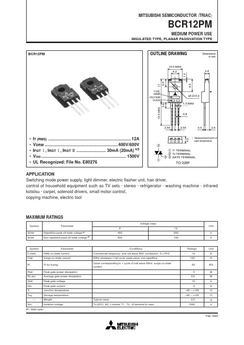
BCR12PM-12LGTriacMedium Power UseREJ03G1510-0100Rev.1.00Feb 14, 2007 Features• I T (RMS) : 12 A• V DRM : 600 V• I FGTI, I RGTI, I RGT III : 30 mA • V iso : 2000V • The Product guaranteed maximum junction temperature 150°C• Insulated Type• Planar Type• UL Recognized : Yellow Card No. E223904File No.E80271OutlineApplicationsSwitching mode power supply, light dimmer, electronic switch, hair dryer, Television, Stereo system, refrigerator,Washing machine, infrared kotatsu, and carper, small motor controller, SS relay, solenoid driver, copying machine,electric tool, electric heater control, and other general purpose control applicationsVoltage classParameter Symbol12UnitRepetitive peak off-state voltage Note1V DRM 600 V Non-repetitive peak off-state voltage Note1V DSM 720 VParameter Symbol Ratings Unit ConditionsRMS on-state current I T (RMS) 12 A Commercial frequency, sine full wave360°conduction, Tc = 92°CSurge on-state current I TSM 120 A 60Hz sinewave 1 full cycle, peak value,non-repetitiveI 2t for fusion I 2t 60 A 2s Value corresponding to 1 cycle of halfwave 60Hz, surge on-state currentPeak gate power dissipation P GM 5 W Average gate power dissipation P G (AV) 0.5 W Peak gate voltage V GM 10 V Peak gate current I GM 2 A Junction Temperature Tj –40 to +150 °C Storage temperature Tstg –40 to +150 °C Mass — 2.0 g Typical value Isolation voltage V iso 2000 V Ta = 25°C, AC 1 minute,T 1 • T 2 • G terminal to caseNotes: 1. Gate open.Electrical CharacteristicsParameter Symbol Min. Typ. Max. Unit Test conditions Repetitive peak off-state current I DRM — — 2.0 mA Tj = 150°C, V DRM applied On-state voltage V TM — — 1.6 V Tc = 25°C, I TM = 20 A,instantaneous measurementΙV FGT Ι — — 1.5V ΙΙ V RGT Ι — — 1.5 V Gate trigger voltage Note2ΙΙΙ V RGT ΙΙΙ — — 1.5 VTj = 25°C, V D = 6 V, R L = 6 Ω,R G = 330 Ω Ι I FGT Ι — — 30 mA ΙΙ I RGT Ι — — 30 mAGate trigger curent Note2ΙΙΙI RGT ΙΙΙ — — 30 mATj = 25°C, V D = 6 V, R L = 6 Ω, R G = 330 Ω Gate non-trigger voltageV GD 0.2/0.1 — — V Tj = 125°C/150°C, V D = 1/2 V DRM Thermal resistanceR th (j-c) — — 4.0 °C/W Junction to case Note3 Critical-rate of rise of off-statecommutation voltageNote4(dv/dt)c 10/1 —— V/µs Tj = 125°C/150°CNotes: 2. Measurement using the gate trigger characteristics measurement circuit.3. The contact thermal resistance R th (j-c) in case of greasing is 0.5°C/W.4. Test conditions of the critical-rate of rise of off-state commutation voltage is shown in the table below.Performance CurvesPackage DimensionsOrder CodeLead form Standard packing Quantity Standard order code Standard order code exampleStraight type Vinyl sack 100Type name BCR12PM-12LG Lead form Plastic Magazine (Tube) 50Type name – Lead forming code BCR12PM-12LG-A8 Note : Please confirm the specification about the shipping in detail.Refer to "/en/network " for the latest and detailed information.Renesas Technology America, Inc.450 Holger Way, San Jose, CA 95134-1368, U.S.A Tel: <1> (408) 382-7500, Fax: <1> (408) 382-7501Renesas Technology Europe LimitedDukes Meadow, Millboard Road, Bourne End, Buckinghamshire, SL8 5FH, U.K.Tel: <44> (1628) 585-100, Fax: <44> (1628) 585-900Renesas Technology (Shanghai) Co., Ltd.Unit 204, 205, AZIACenter, No.1233 Lujiazui Ring Rd, Pudong District, Shanghai, China 200120Tel: <86> (21) 5877-1818, Fax: <86> (21) 6887-7898Renesas Technology Hong Kong Ltd.7th Floor, North Tower, World Finance Centre, Harbour City, 1 Canton Road, Tsimshatsui, Kowloon, Hong Kong Tel: <852> 2265-6688, Fax: <852> 2730-6071Renesas Technology Taiwan Co., Ltd.10th Floor, No.99, Fushing North Road, Taipei, Taiwan Tel: <886> (2) 2715-2888, Fax: <886> (2) 2713-2999Renesas Technology Singapore Pte. Ltd.1 Harbour Front Avenue, #06-10, Keppel Bay Tower, Singapore 098632 Tel: <65> 6213-0200, Fax: <65> 6278-8001Renesas Technology Korea Co., Ltd.Kukje Center Bldg. 18th Fl., 191, 2-ka, Hangang-ro, Yongsan-ku, Seoul 140-702, Korea Tel: <82> (2) 796-3115, Fax: <82> (2) 796-2145Renesas Technology Malaysia Sdn. BhdUnit 906, Block B, Menara Amcorp, Amcorp Trade Centre, No.18, Jalan Persiaran Barat, 46050 Petaling Jaya, Selangor Darul Ehsan, Malaysia Tel: <603> 7955-9390, Fax: <603> 7955-9510RENESAS SALES OFFICES。
BCR12PM中文资料
2.8
17 5.0
1.2
TYPE NAME VOLTAGE CLASS
φ3.2±0.2
13.5 MIN
3.6
1.3 MAX
0.8
2.54
2.54
8.5
0.5
2.6
• • • • •
IT (RMS) ...................................................................... 12A VDRM ..............................................................400V/600V IFGT !, IRGT !, IRGT # ......................... 30mA (20mA) V5 Viso ........................................................................ 1500V UL Recognized: File No. E80276
101 –60 –40 –20 0 20 40 60 80 100 120 140 JUNCTION TEMPERATURE (°C) MAXIMUM TRANSIENT THERMAL IMPEDANCE CHARACTERISTICS (JUNOLTAGE VS. JUNCTION TEMPERATURE
123 2
∗ Measurement point of case temperature
1
1 T1 TERMINAL 2 T2 TERMINAL 3 3 GATE TERMINAL
TO-220F
APPLICATION Switching mode power supply, light dimmer, electric flasher unit, hair driver, control of household equipment such as TV sets · stereo · refrigerator · washing machine · infrared kotatsu · carpet, solenoid drivers, small motor control, copying machine, electric tool
新代参数设定参考手册--V9.4(1)(精)

新代科技參數設定說明手冊by : 新代科技date : 2006/09/05ver : 9.4版本更新記錄目錄1. 系統基本參數設定 ................................................................................ 5 1.1硬體環境設定 ................................................................................... 5 1.1.1軸卡基本參數設定 . .......................................................................... 5 1.1.1.1 Pr01 軸板基址 ................................................................................... 5 1.1.1.2 Pr09 軸板型態 ................................................................................... 6 1.1.1.3 Pr10 伺服警報接點型態 ........................................................................... 6 1.1.1.4 Pr11 軸卡時脈來源 ............................................................................... 7 1.1.1.5 Pr12 SERVO6軸卡最高時脈 . ........................................................................ 7 1.1.1.6 Pr13 軸卡數目 ................................................................................... 7 1.1.2 I/O卡基本參數設定 . ........................................................................ 8 1.1.2.1 Pr03 I/O板基址 .................................................................................. 8 1.1.2.2 Pr05 I/O板組態 . ................................................................................ 8 1.1.2.3 Pr15 I/O卡數位濾波程度 . ........................................................................ 11 1.1.3 控制精度設定 ............................................................................. 12 1.1.3.1 Pr17控制精度 .................................................................................. 12 1.1.4 螢幕功能鍵型態設定 ....................................................................... 12 1.1.4.1 Pr3205功能鍵型態 . .............................................................................. 12 1.1.5 螢幕型別 ................................................................................. 13 1.1.5.1 Pr3211 螢幕型別 ................................................................................ 13 1.1.6預設外部存取資料磁碟機代號 . ............................................................... 13 1.1.6.1 Pr3213 磁碟機代號 .............................................................................. 13 1.1.7 選擇控制面板鍵盤型態 ..................................................................... 13 1.1.7.1 Pr3217 選擇控制面板鍵盤型別 .................................................................... 13 1.1.8系統掃瞄時間設定 . ......................................................................... 14 1.1.8.1 Pr3202 I/O掃描時間 . ............................................................................ 14 1.1.8.2 Pr3203 運動補間時間 ............................................................................ 14 1.1.8.3 Pr3204 PLC掃描時間 . ............................................................................ 14 1.2軟體介面環境參數設定 .......................................................................... 15 1.2.1應用功能參數設定 . ......................................................................... 15 1.2.1.1 Pr411 G00運動方式 . ............................................................................. 15 1.2.1.2 Pr413 G92(G92.1座標保留模式設定 ............................................................... 15 1.2.1.3 Pr414 工件座標系統保留模式 ..................................................................... 15 1.2.1.4 Pr415 重置或關機時保留目前刀長資料 ............................................................. 16 1.2.1.5 Pr3207 C/S界面版本編號 . ........................................................................ 16 1.2.1.6 Pr3215選刀時呼叫副程式 . ........................................................................ 16 1.2.1.7 Pr3241 工件程式小數點型態 . (16)1.2.1.8 Pr3243 鍵盤重置鍵由 PLC 處理 ....................................................................17 1.2.1.9 Pr3245刀長磨耗補償輸入增量最大值 ............................................................... 17 1.2.1.10 Pr3801 G95時進給量與主軸位置緊密偶合 .......................................................... 17 1.2.1.11 Pr3807圓弧終點不在圓弧上檢查視窗 .............................................................. 18 1.2.1.12 Pr3809 UVW為 XYZ 軸增量指令 . .................................................................. 18 1.2.1.13 Pr3815 刀具半徑補償預看模式 ................................................................... 18 1.2.1.14 Pr3816 刀長補償模式 .......................................................................... 18 1.2.1.15 Pr3819過切檢查型態 . ........................................................................... 19 1.2.1.16 Pr3851斷刀處理程式號碼 . ....................................................................... 19 1.2.2 系統人機介面設定 ......................................................................... 20 1.2.2.1 Pr3201 設定啟動車床規則 ........................................................................ 20 1.2.2.2 Pr3209 語言設定 ................................................................................ 20 1.2.2.3 Pr3219 系統安裝組態 ............................................................................ 21 1.2.2.4 Pr3221 除錯模式 ................................................................................ 21 1.2.2.5 Pr3223啟動系統管理功能 . ........................................................................ 22 1.2.2.6 Pr3225 螢幕保護功能延遲時間 .................................................................... 22 1.2.2.7 Pr3227 螢幕解析度 .............................................................................. 22 1.2.2.8 Pr3229 關閉工件座標系統功能 .. (22)1.2.2.9 Pr3247 速率顯示方法 (23)2. 伺服軸向參數設定 ............................................................................... 24 2.1各軸對應機械軸設定 ............................................................................ 24 2.1.1 Pr21~Pr40 伺服對應的機械軸 ............................................................... 24 2.2軸向馬達運動方向的設定 . ....................................................................... 24 2.2.1 Pr41~Pr60 馬達運動方向設定 ............................................................... 24 2.3軸向命令與回授解析度設定 . ..................................................................... 25 2.3.1 Pr61~Pr80 位置感測器解析度 ............................................................... 25 Pr81~Pr100 軸卡回授倍頻 ........................................................................ 25 Pr121~Pr160 螺桿側齒輪齒數 , 馬達側齒輪齒數 ...................................................... 25 Pr161~Pr180 螺桿寬度(Pitch .................................................................... 25 Pr181~Pr200 伺服系統的位置迴路增益 ............................................................. 25 Pr201~Pr220 位置感測器型態 ..................................................................... 25 Pr341~Pr360 位置命令倍率分子 ................................................................... 25 Pr361~Pr380 位置命令倍率分母 ................................................................... 25 2.4各軸向應用型態設定 . ........................................................................... 27 2.4.1 Pr221~Pr226軸型態 . ....................................................................... 27 2.4.2 Pr281~Pr300選擇半徑軸或直徑軸 . ........................................................... 28 2.5各軸向顯示名稱設定 . ........................................................................... 28 2.5.1 Pr321~Pr340設定軸的名稱 . (28)2.6軸向控制模式設定 . ............................................................................. 29 2.6.1 Pr381~Pr400位置伺服控制模式 . ............................................................. 29 2.7定位檢查功能設定 . ............................................................................. 29 2.7.1 Pr421~Pr440切削時位置檢查的視窗範圍 ...................................................... 29 2.7.2 Pr481~Pr500 快速移動 (Rapid Travel, G00時位置檢查的視窗範圍 .............................. 30 2.7.3Pr561~Pr580 遺失位置檢查視窗 ............................................................. 30 2.7.4Pr901~Pr920 零速檢查視窗 ................................................................. 30 2.8各軸向左右軟體行程極限保護 . ................................................................... 30 2.8.1Pr2401~Pr2440 軟體第一行程保護的範圍 (30)2.8.2 Pr2441~Pr2480 軟體第二行程保護的範圍 .....................................................313. 主軸參數設定 ................................................................................... 32 3.1主軸對應命令輸出埠設定 (32)3.1.1 Pr1621~Pr1630 主軸對應的機械軸或邏輯軸 ...................................................324. 軸向運動特性設定參數 ........................................................................... 33 4.1切削時前加減速運動規劃 . ....................................................................... 33 4.1.1 Pr401 切削加減速時間 .................................................................... 33 Pr402 重力加速度加減速時間 ..................................................................... 33 Pr405 切削的最高進給速度 ....................................................................... 33 Pr541~Pr560 各軸切削的加減速時間 ............................................................... 33 Pr621~Pr640 各軸切削的最高進給速度 ............................................................. 33 Pr641~Pr660 各軸重力加速度加減速時間 ........................................................... 33 4.2切削時後加減速運動規劃 . ....................................................................... 35 4.2.1 Pr404後加減速切削鐘型加減速時間 . ......................................................... 35 4.3切削時直線轉角自動減速功能 . ................................................................... 37 4.3.1 Pr406轉角參考速度 . ....................................................................... 37 4.4切削時圓弧切削運動最高進給速度設定 ............................................................ 38 4.4.1 Pr408 半徑 5mm 圓弧切削參考速度 ........................................................... 38 4.5快速移動及 JOG 時的加減速規劃 .................................................................. 39 4.5.1 Pr441~Pr460 各軸快速移動 (G00的加減速時間 ............................................... 39 Pr461~Pr480 各軸快速移動 (G00的最高進給速度 .................................................... 39 Pr501~Pr520 各軸快速移動 (G00的F0速度 ......................................................... 39 Pr521~Pr540 各軸 JOG 速度 ....................................................................... 39 1P R 941~960啟動尋原點柵格功能 ................................................................. 40 2P R 1361~PR 1400圓弧尖角補償 . ................................................................... 43 3P R 3217選擇控制面板鍵盤型別 .................................................................. 44 4P R 3821~PR 3822軸偶合軸號 ..................................................................... 45 5P R 3823~PR 3824軸偶合軸號 (46)6P R 3825軸偶合型態 ............................................................................ 47 7P R 3851斷刀處理程式號碼 . (48)1. 系統基本參數設定1.1硬體環境設定1.1.1軸卡基本參數設定1.1.1.1 Pr01 軸板基址軸卡二片以下Pr01→800 軸卡超過二片Pr01→7682.Servo_6的第一片軸卡基址為 768(目前一部控制器僅支援一張 Servo_6,不可與 Servo_4混插3.Embedded 第一片軸卡基址固定為 5121.1.1.2 Pr09 軸板型態0:EMP21:SVO4+不檢查伺服警報2:SVO4+伺服警報接點為常開接點 Normal Open( A 接點 3:SVO4+伺服警報接點為常閉接點 Normal Close( B 接點 4:EMP45:SERVO69:虛擬軸卡1.1.1.3 Pr10 伺服警報接點型態0: SERVO 6軸卡警報為常開接點 Normal Open( A 接點 1: SERVO 6軸卡警報為常閉接點 Normal Close( B 接點1.1.1.4 Pr11 軸卡時脈來源此參數為設定軸卡時脈來源:設定 0為使用軸卡自已時脈設定 1為共用控制器底板 IPC Bus時脈設定 2為共用主機板 VIA 時脈設定原則:一體機控制器→請設定『 0』非一體機控制器→請設定『 2』舊型 486主機板控制器→請設定『 1』1.1.1.5 Pr12 SERVO6軸卡最高時脈此參數為設定 Servo6軸版最高時脈。
RC12中文资料
RC02/12/22/32 1%
The resistive layer is covered with a protective coat and printed with the resistance value (no printing on RC22H and RC32). Finally, the two external end terminations are added. For ease of soldering the outerlayer of these end terminations is a lead/tin alloy.
元器件交易网
Phycomp
Product specification
Precision chip resistors sizes 1206, 0805, 0603 and 0402
FEATURES Low assembly costs High component and equipment reliability Excellent performance at high frequency, especially the RC32. TC 50 in thick film technology Complete precision SMD family. APPLICATIONS All general purpose applications. QUICK REFERENCE DATA VALUE DESCRIPTION RC02H Size code Resistance range Resistance tolerance and E-series Temperature coefficient; note 1: 1 W R 10 W 10 W < R 10 MW Maximum dissipation at Tamb = 70 C Maximum permissible voltage Climatic category (IEC 60068) Basic specification Note 1. All TC values should be multiplied by 10-6/K. 250 250 100 0.25 W 200 V (DC or RMS) 50 250 250 100 0.125 W 150 V (DC or RMS) 55/155/56 IEC 60115-8 50 1 W to 10 MW RC02G 90 W to 2.74 MW RC12H 1 W to 10 MW RC12G 90 W to 2.74 MW DESCRIPTION The resistors are constructed on a high grade ceramic body (aluminium oxide). Internal metal electrodes are added at each end and connected by a resistive paste which is applied to the top surface of the substrate. The composition of the paste is adjusted to give the approximate resistance required and the value is trimmed to within tolerance, by laser cutting of this resistive layer.
MAX812中文资料

ELECTRICAL CHARACTERISTICS
(VCC = 5V for L/M versions, VCC = 3.3V for T/S versions, VCC = 3V for R version, TA = 0°C to +70°C, unless otherwise noted. Typical values are at TA = +25°C.) (Note 1) PARAMETER VCC Range Supply Current ICC MAX81_L/M, VCC = 5.5V, IOUT = 0A MAX81_R/S/T, VCC = 3.6V, IOUT = 0A MAX81_L MAX81_M Reset Threshold (Note 2) VTH MAX81_T MAX81_S MAX81_R Reset Threshold Tempco VCC to Reset Delay (Note 2) Reset Active Timeout Period MR Minimum Pulse Width MR Glitch Immunity (Note 3) MR to Reset Propagation Delay (Note 2) tMD VIH MR Input Threshold VIL VIH VIL MR Pull-Up Resistance VOH RESET Output Voltage (MAX812) ISOURCE = 150µA, 1.8V < VCC < VTH(MIN) MAX812R/S/T only, ISINK = 1.2mA, VCC = VTH(MAX) MAX812L/M only, ISINK = 3.2mA, VCC = VTH(MAX) VCC > VTH(MAX), MAX81_L/M VCC > VTH(MAX), MAX81_R/S/T 2.3 0.8 0.7 x VCC 0.25 x VCC 10 0.8VCC 0.3 0.4 V 20 30 kΩ V tRP tMR VOD = 125mV, MAX81_L/M VOD = 125mV, MAX81_R/S/T VCC = VTH(MAX) 140 10 100 0.5 4.50 4.25 3.00 2.85 2.55 SYMBOL CONDITIONS MIN 1.0 6 2.7 4.63 4.38 3.08 2.93 2.63 30 40 20 560 TYP MAX 5.5 15 10 4.75 4.50 3.15 3.00 2.70 ppm/°C µs ms µs ns µs V UNITS V µA
HM化学品限制

H&M 化学品限制条款,2005 年 10 月
1....................................................................................................................................................................................3 产品中限制使用的物质名称 ..........................................................................................................................................................4 偶氮染料和涂料 ........................................................................................................................................................................4 分散染料...................................................................................................................................................................................5 其它染料........................................................
SA12中文资料

SA12中⽂资料SA5.0thruSA170AFEATURES:ECONOMICAL SERIESAVAILABLE IN BOTH UNIDIRECTIONAL AND BI-DIRECTIONAL CONSTRUCTION 5.0 TO 170 STAND-OFF VOLTAGE AVAILABLE ? 500 WATTS PEAK PULSE POWER DISSIPATION ?QUICK RESPONSEDESCRIPTION:This Transient Voltage Suppressor is an economical, molded, commercial product used to protect voltage sensitive components from destruction or partial degradation.The response time of their clamping action is virtually instantaneous (1 x 10-12seconds) and they have a peak pulse power rating of 500 watts for 1 ms as depicted in Figure 1 and 2. Microsemi also offers a great variety of other Transient Voltage Suppressor's to meet higher and lower power demands and special applications. MAXIMUM RATINGS:Peak Pulse Power Dissipation at 25°C: 500 WattsSteady State Power Dissipation: 2.5 Watts at T L = +75°C3/8" Lead Lengtht clamping (0 volts to BV Min.):Unidirectional <1x10-12 Seconds: Bi-directional <5x10⁻⁹Seconds.Operating and Storage Temperature: -55° to +175°C8700 E. Thomas Road Scottsdale, AZ 85252Phone: (480) 941-6300Fax: (480) 947-15035.0 thru 170 volts500 Watts Transient Voltage Suppressors2 x ?.032 ± .002[.81 ± .05].107[2.72]max.POLARITYMark {cathode}.205[5.21]MAX.NOTE: DIMENSIONS IN [ ] =MILLIMETERSP E A K P U L S E P O W E R (P p p ) O R C O N T I N U O U S P O W E R I N P E R C E N T O F 25°C R A T I N G FIGURE 1DERATING CURVE50100150175255075100TYPICAL CHARACTERISTIC CURVEST L LEAD TEMPERATURE °CPulse Time Duration (tp) is Defined as that point where Ip decaysto 50% of I surgePeak Value Ipp 100501234TIME (t) IN MILLISECONDSFIGURE 2PULSE WAVEFORM FOR EXPONENTIAL SURGEP U L S E C U R R E N T I N P E R C E N T O F I p pMECHANICALCHARACTERISTICSCASE: Void free transfer molded thermosetting plastic.FINISH: Readily solderable.POLARITY: Band denotes cathode. Bi-directional not marked.WEIGHT: 0.7 gram (Appx.).MOUNTING POSITION: AnyDO-412 X1.10[27.94]MIN.SA170A ELECTRICAL CHARACTERISTICS AT 25°C PART NUMBERBREAKDOWNVOLTAGE V(BR)MIN.MAXTESTCURRENTI TRATEDSTANDOFFVOLTAGEV WMMAX. REVERSESTANDBYCURRENTI D @V WMMAX.PEAKREVERSEVOLTAGEV C MAX.@ I PPMAX. PEAKPULSECURRENTI PP(Figure 2)MAX.TEMP.COEFFICIENTOF V(BR)-55°C TOαV(BR) VOLTS VOLTS mA VOLTSµ ADC VOLTS AMP% / °CSA5.0 6.407.3010 5.06009.652.057 SA5.0A 6.407.0010 5.06009.254.3.057 SA6.0 6.678.1510 6.060011.443.9.059 SA6.0A 6.677.3710 6.060010.348.5.059 SA6.57.228.8210 6.540012.340.7.061 SA6.5A7.227.9810 6.540011.244.7.061SA7.07.789.51107.015013.337.8.065 SA7.0A7.788.60107.015012.041.7.065 SA7.58.3310.217.55014.335.0.067SA7.5A8.339.2117.55012.938.8.067 SA8.08.8910.918.02515.033.3.070 SA8.0A8.899.8318.02513.636.7.070SA8.59.4411.518.5515.931.4.073 SA8.5A9.4410.418.5514.434.7.073 SA9.010.012.219.0116.929.5.076SA9.0A10.011.119.0115.432.5.076 SA1011.113.6110118.826.6.078 SA10A11.112.3110117.029.4.078SA1112.214.9111120.124.9.081 SA11A12.213.5111118.227.4.081 SA1213.316.3112122.022.7.082SA12A13.314.7112119.925.1.082 SA1314.417.6113123.821.0.084 SA13A14.415.9113121.523.2.084SA1415.619.1114125.819.4.086 SA14A15.617.2114123.221.5.086 SA1516.720.4115126.918.8.087SA15A16.718.5115124.420.6.087 SA1617.821.8116128.817.6.088 SA6A17.819.7116126.019.2.088SA1718.923.1117130.516.4.090 SA17A18.920.9117127.618.1.090 SA1820.024.4118132.215.5.092SA18A20.022.1118129.217.2.092 SA2022.227.1120135.813.9.093 SA20A22.224.5120132.415.4.093thruSA170A ELECTRICAL CHARACTERISTICS AT 25°CPART NUMBERBREAKDOWNVOLTAGE V(BR)MIN.MAXTESTCURRENTI TRATEDSTANDOFFVOLTAGEV WMMAX. REVERSESTANDBYCURRENTI D @V WMMAX.PEAKREVERSEVOLTAGEV C MAX.@ I PPPULSECURRENTI PP(Figure 2)MAX.TEMP.COEFFICIENTOF V(BR)-55°C TO175°CαV(BR) VOLTS VOLTS mA VOLTSµ ADC VOLTS AMP% / °CSA2224.429.8122139.412.7.094 SA22A24.426.9122135.514.1.094 SA2426.732.6124143.011.6.096SA24A26.729.5124138.912.8.096 SA2628.935.3126146.610.7.097 SA26A28.931.9126142.111.9.097SA2831.138.0128150.09.9.098 SA28A31.134.4128145.411.0.098 SA3033.340.7130153.59.3.099SA30A33.336.8130148.410.3.099 SA3336.744.9133159.08.5.100 SA33A36.740.6133153.39.4.100SA3640.048.9136164.37.8.101 SA36A40.044.2136158.18.6.101 SA4044.454.3140171.47.0.101SA40A44.449.1140164.57.8.101 SA4347.858.4143176.7 6.5.102 SA43A47.852.8143169.47.2.102 SA4550.061.1145180.3 6.2.102 SA45A50.055.3145172.7 6.9.102 SA4853.365.1148185.5 5.8.103 SA48A53.358.9148177.4 6.5.103SA5156.769.3151191.1 5.5.103 SA51A56.762.7151182.4 6.1.103 SA5460.073.3154196.3 5.2.104SA54A60.066.3154187.1 5.7.104 SA5864.478.71581103.0 4.9.104 SA58A64.471.2158193.6 5.3.104SA6066.781.51601107.0 4.7.104 SA60A66.773.7160196.8 5.2.104 SA6471.186.91641114.0 4.4.105SA64A71.178.61641103.0 4.9.105 SA7077.895.11701125.0 4.0.105 SA70A77.886.01701113.0 4.4.105SA7583.3102.01751134.0 3.7.105 SA75A83.392.11751121.0 4.1.105thruSA170A ELECTRICAL CHARACTERISTICS AT 25°CPART NUMBERBREAKDOWNVOLTAGE V(BR)MIN.MAXTESTCURRENTI TRATEDSTANDOFFVOLTAGEV WMMAX. REVERSECURRENTI D @V WMMAX.PEAKREVERSEVOLTAGEV C MAX.@ I PPMAX. PEAKPULSECURRENTI PP(Figure 2)MAX.TEMP.COEFFICIENTOF V(BR)-55°C TO175°CαV(BR) VOLTS VOLTS mA VOLTSµ ADC VOLTS AMP% / °CSA7886.7106.01781139.0 3.6.106 SA78A86.795.81781126.0 4.0.106 SA8594.4115.01851151.0 3.3.106SA85A94.4104.01851137.0 3.6.106 SA90100.0122.01901160.0 3.1.107 SA90A100.0111.01901146.0 3.4.107SA100111.0136.011001179.0 2.8.107 SA100A111.0123.011001162.0 3.1.107 SA110122.0149.011101196.0 2.6.107SA110A122.0135.011101177.0 2.8.107 SA120133.0163.011201214.0 2.3.107 SA120A133.0147.011201193.0 2.0.107SA130144.0176.011301231.0 2.2.108 SA130A144.0159.011301209.0 2.4.108 SA150167.0204.011501268.0 1.9.108SA150A167.0185.011501243.0 2.1.108 SA160178.0218.011601287.0 1.7.108 SA160A178.0197.011601259.0 1.9.108SA170189.0231.011701304.0 1.6.108 SA170A189.0209.011701275.0 1.8.108 Note: For Bi-directional construction, indicate a C or CA suffix after the part number, i.e. SA5.0CAthru SA170A10010C -C A P A C I T A N C E - P I C O F A R AD S1001001000V (BR)- BREAKDOWN VOLTAGE - VOLTSFIGURE 3TYPICAL CAPACITANCE VS BREAKDOWN VOLTAGE107.05.03.02.01.00.70.50.30.20.10.11.010********0.20.5 2.0 5.020*********tw - Pulse Width µsFIGURE 4PEAK PULSE POWER VS. PULSE TIME(P P P ) - P e a k P u l s e P o w e r , (k W )20305070。
Max 4-8-12 中文说明书
LB1930 Max 4 - 8 - 12安装尺寸调节参数启动和调节油泵0.45bar 避免油泵损坏。
在调试燃烧器时,油泵压力设置在12bar 。
在启动燃烧器前,通过计压表端口使空气排出油泵。
在管道里注入些轻油作为油泵点燃启动。
启动燃烧器并且检查油泵工作压力。
如果在第一次清洗时,油泵没有启动成功,结果燃烧器会停止锁定,按动控制器上的按钮重新启动燃烧器。
如果油泵启动成功,燃烧器在前吹扫后停止,说明燃料压力在油泵内下降,重启燃烧器。
不要让油泵在没有油的情况下运行超过3分钟。
油嘴清洗和置换使用适合的套筒扳手来移开油嘴,请小心不要损坏到电极。
在安装新的油嘴时同样小心电极。
注意:在更换油嘴后总是要检查电极的位置(参考图解)。
电极位置不正确会引起点火问题。
燃烧器的启动和调节在安装好燃烧器后,请检查以下几点: − 工作电压和主电路是否保护保险丝 − 管道系统长度是否正确,是否密封 − 燃料类型必须适用于燃烧器− 锅炉的温度调节装置连接是否正确以及安全装置 − 马达运行的方向是否正确− 保护马达热保护的正确数据标准是否有当以上所有条件都具备,然后可以开始启动调试燃烧器。
打开燃烧器的开关。
控制器会同时给点火变压器和电机命令,12秒前吹扫烧室。
在吹扫结束后,控制器命令打开燃料泵的电磁阀,点火变压器制造火花,燃烧器点火。
在安全间隔5秒后,点火成功,控制器关闭点火变压器。
如果燃烧器点火出现故障,控制器会在10秒内命令燃烧器进入安全状态。
在这时,在燃烧器进入安全停止状态后的30秒内不要手工重启燃烧器。
燃料泵反馈压力必须维持在12bar 左右。
注意:在预热阶段,燃烧头预热运行需要1分钟。
在这种情况下,要命令锅炉温度调节器,点火信号应当由预热器上的温度调节器来发出。
小燃烧枪管分解图TC= SHORT HEAD TL = LONG HEADTC= SHORT HEAD TL = LONG HEAD。
H78M12AT中文资料

current limiting, thermal shut-down and safe operating area protection, making it essentially indestructible. If adequate heat sinking is provided, they can deliver over 0.5A output current. Although designed primarily as fixed voltage regulators, this device can be used with external components to obtain adjustable voltages and currents.Description• Output current up to 500mA is available.Page No. : 2/3Electrical Characteristics• H78M12ATVin=19V, Io=350mA, 0°C≤Tj≤125°C, PD≤5W, unless otherwise specifiedSymbol Characteristic Min Typ Max Units Vo Output Voltage (Tj=25°C)11.641212.36V Vo Output Voltage (14.5V≤Vin≤27V, 5mA≤Io≤350mA)11.521212.48V Line Regulation (Tj=25°C, Io=200mA), 14.5V≤Vin≤30V-20100 ReglinemV Line Regulation (Tj=25°C, Io=200mA), 16V≤Vin≤30V-1650Load Regulation (Tj=25°C), 5mA≤Io≤500mA--220 RegloadmV Load Regulation (Tj=25°C), 5mA≤Io≤200mA--110 IB Quiescent Current (Tj=25°C)- 3.26mA Quiescent Current Change (Tj=25°C), 14.5V≤Vin≤30V, Io=200mA--0.8mA ∆IBQuiescent Current Change (Tj=25°C), 5mA≤Io≤350mA--0.5 RR Ripple Rejection, 15V≤Vin≤25V, Io=300mA, f=120Hz55--dB Vi-Vo Dropout Voltage (Io=500mA, Tj=25°C)-2-V VN Output Noise Voltage (Tj=25°C), 10Hz≤f≤100KHz-75160uV Isc Short Circuit Current Limit (Tj=25°C), Vin=35V-300-mA Imax Peak Output Current (Tj=25°C)-700-mA TCVo Average Temperature Coefficient of Output Voltage, Io=5mA--0.5-mV/°C • H78M12BTVin=19V, Io=350mA, 0°C≤Tj≤125°C, PD≤5W, unless otherwise specifiedSymbol Characteristic Min Typ Max Units Vo Output Voltage (Tj=25°C)11.41212.6V Vo Output Voltage (14.5V≤Vin≤27V, 5mA≤Io≤350mA)11.41212.6VLine Regulation (Tj=25°C, Io=200mA), 14.5V≤Vin≤30V-20120 ReglinemV Line Regulation (Tj=25°C, Io=200mA), 16V≤Vin≤30V-1660Load Regulation (Tj=25°C), 5mA≤Io≤500mA--240mV RegloadLoad Regulation (Tj=25°C), 5mA≤Io≤200mA--120 IB Quiescent Current (Tj=25°C)- 3.26mAQuiescent Current Change (Tj=25°C), 14.5V≤Vin≤30V, Io=200mA--1mA ∆IBQuiescent Current Change (Tj=25°C), 5mA≤Io≤350mA--0.6 RR Ripple Rejection, 15V≤Vin≤25V, Io=300mA, f=120Hz55--dB Vi-Vo Dropout Voltage (Io=500mA, Tj=25°C)-2-V VN Output Noise Voltage (Tj=25°C), 10Hz≤f≤100KHz-75180uV Isc Short Circuit Current Limit (Tj=25°C), Vin=35V-300-mA Imax Peak Output Current (Tj=25°C)-700-mA TCVo Average Temperature Coefficient of Output Voltage, Io=5mA--0.5-mV/°CPage No. : 3/3 TO-126 DimensionImportant Notice:• All rights are reserved. Reproduction in whole or in part is prohibited without the prior written approval of HSMC.• HSMC reserves the right to make changes to its products without notice.•HSMC semiconductor products are not warranted to be suitable for use in Life-Support Applications, or systems.• HSMC assumes no liability for any consequence of customer product design, infringement of patents, or application assistance. Head Office And Factory :•Head Office (Hi-Sincerity Microelectronics Corp.) : 10F.,No. 61, Sec. 2, Chung-Shan N. Rd. Taipei Taiwan R.O.C.Tel : 886-2-25212056 Fax : 886-2-25632712, 25368454•Factory 1 : No. 38, Kuang Fu S. Rd., Fu-Kou Hsin-Chu Industrial Park Hsin-Chu Taiwan. R.O.CTel : 886-3-5983621~5 Fax : 886-3-5982931。
BCR8PM-12LD-A8中文资料
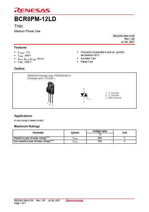
BCR8PM-12LDTriacMedium Power UseREJ03G1564-0100Rev.1.00Jul 06, 2007 Features• I T (RMS) : 8 A• V DRM : 600 V• I FGTI , I RGTI, I RGTIII : 50 mA • Viso : 2000 V • The product guaranteed maximum junction temperature 150°C.• Insulated Type• Planar TypeOutlineApplicationsMotor control, heater controlMaximum RatingsVoltage classParameter Symbol12UnitRepetitive peak off-state voltage Note1V DRM 600 V Non-repetitive peak off-state voltage Note1V DSM 700 VParameter Symbol Ratings Unit ConditionsRMS on-state current I T (RMS) 8 A Commercial frequency, sine full wave360° conduction, Tc = 85°CSurge on-state current I TSM 48 A 60Hz sinewave 1 full cycle, peak value,non-repetitiveI 2t for fusing I 2t 9.5 A 2s Value corresponding to 1 cycle of halfwave 60Hz, surge on-state currentPeak gate power dissipation P GM 5 W Average gate power dissipation P G (AV) 0.5 W Peak gate voltage V GM 10 V Peak gate current I GM 2 A Junction temperature Tj – 40 to +150 °C Storage temperature Tstg – 40 to +150 °C Mass — 2.0 g Typical value Isolation voltage Viso 2000 V Ta = 25°C, AC 1 minute,T 1·T 2·G terminal to case Notes: 1. Gate open.Electrical CharacteristicsParameter Symbol Min. Typ. Max. Unit Test conditionsRepetitive peak off-state current I DRM — — 2.0 mA Tj = 125°C, V DRM applied On-state voltage V TM — — 2.0 V Tc = 25°C, I TM = 12 A,Instantaneous measurementΙ V FGT Ι — — 1.5V ΙΙ V RGT Ι — — 1.5 VGate trigger voltage Note2ΙΙΙ V RGT ΙΙΙ — — 1.5 VTj = 25°C, V D = 6 V, R L = 6 Ω,R G = 330 Ω Ι I FGT Ι — — 50 mA ΙΙ I RGT Ι — — 50 mAGate trigger current Note2ΙΙΙ I RGT ΙΙΙ — — 50 mATj = 25°C, V D = 6 V, R L = 6 Ω,R G = 330 Ω Gate non-trigger voltage V GD 0.2 — — V Tj = 125°C, V D = 1/2 V DRM Thermal resistance R th (j-c) — — 4.9 °C/W Junction to case Note3 Critical-rate of rise of off-statecommutating voltageNote4(dv/dt)c 10 — — V/µs Tj = 125°CNotes: 2. Measurement using the gate trigger characteristics measurement circuit.3. The contact thermal resistance R th (c-f) in case of greasing is 0.5°C/W.4. Test conditions of the critical-rate of rise of off-state commutating voltage is shown in the table below.Performance CurvesPackage DimensionsOrder CodeLead form Standard packing Quantity Standard order code Standard order code exampleStraight type Vinyl sack 100Type name BCR8PM-12LD Lead form Plastic Magazine (Tube) 50Type name – Lead forming code BCR8PM-12LD-A8 Note : Please confirm the specification about the shipping in detail.Refer to "/en/network " for the latest and detailed information.Renesas Technology America, Inc.450 Holger Way, San Jose, CA 95134-1368, U.S.A Tel: <1> (408) 382-7500, Fax: <1> (408) 382-7501Renesas Technology Europe LimitedDukes Meadow, Millboard Road, Bourne End, Buckinghamshire, SL8 5FH, U.K.Tel: <44> (1628) 585-100, Fax: <44> (1628) 585-900Renesas Technology (Shanghai) Co., Ltd.Unit 204, 205, AZIACenter, No.1233 Lujiazui Ring Rd, Pudong District, Shanghai, China 200120Tel: <86> (21) 5877-1818, Fax: <86> (21) 6887-7898Renesas Technology Hong Kong Ltd.7th Floor, North Tower, World Finance Centre, Harbour City, 1 Canton Road, Tsimshatsui, Kowloon, Hong Kong Tel: <852> 2265-6688, Fax: <852> 2730-6071Renesas Technology Taiwan Co., Ltd.10th Floor, No.99, Fushing North Road, Taipei, Taiwan Tel: <886> (2) 2715-2888, Fax: <886> (2) 2713-2999Renesas Technology Singapore Pte. Ltd.1 Harbour Front Avenue, #06-10, Keppel Bay Tower, Singapore 098632 Tel: <65> 6213-0200, Fax: <65> 6278-8001Renesas Technology Korea Co., Ltd.Kukje Center Bldg. 18th Fl., 191, 2-ka, Hangang-ro, Yongsan-ku, Seoul 140-702, Korea Tel: <82> (2) 796-3115, Fax: <82> (2) 796-2145Renesas Technology Malaysia Sdn. BhdUnit 906, Block B, Menara Amcorp, Amcorp Trade Centre, No.18, Jalan Persiaran Barat, 46050 Petaling Jaya, Selangor Darul Ehsan, Malaysia Tel: <603> 7955-9390, Fax: <603> 7955-9510RENESAS SALES OFFICES。
AX-12完整中文资料
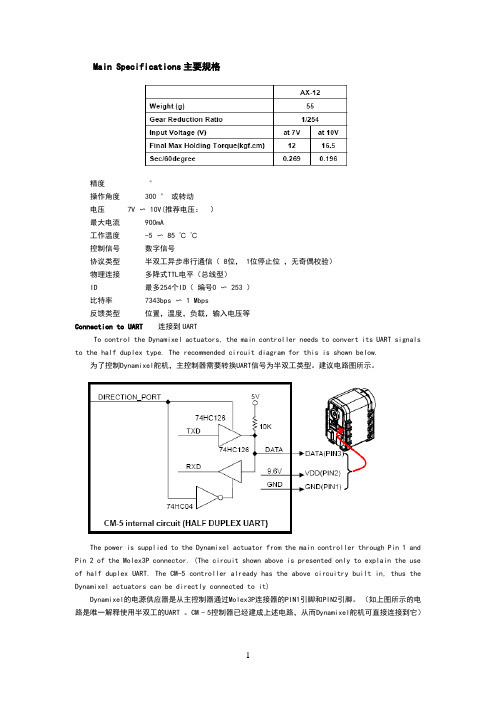
Main Specifications主要规格精度°操作角度300 ° 或转动电压7V 〜 10V(推荐电压:)最大电流900mA工作温度-5 〜 85 ℃℃控制信号数字信号协议类型半双工异步串行通信( 8位, 1位停止位,无奇偶校验)物理连接多降式TTL电平(总线型)ID 最多254个ID(编号0 〜 253 )比特率7343bps 〜 1 Mbps反馈类型位置,温度,负载,输入电压等Connection to UART 连接到UARTTo control the Dynamixel actuators, the main controller needs to convert its UART signals to the half duplex type. The recommended circuit diagram for this is shown below.为了控制Dynamixel舵机,主控制器需要转换UART信号为半双工类型。
建议电路图所示。
The power is supplied to the Dynamixel actuator from the main controller through Pin 1 and Pin 2 of the Molex3P connector. (The circuit shown above is presented only to explain the use of half duplex UART. The CM-5 controller already has the above circuitry built in, thus the Dynamixel actuators can be directly connected to it)Dynamixel的电源供应器是从主控制器通过Molex3P连接器的PIN1引脚和PIN2引脚。
RT32钢和R-8M钢的性能对比和参考

RT32钢和R-8M钢的性能对比和参考RT32钢和R-8M钢它们都是冷作模具钢,都具有较高的耐磨性性RT32钢冷作模具钢的特性,高耐磨性和韧性,良好的全淬硬性,优越的淬后尺寸稳定性,良好的抗回火软化性能。
供货状态及硬度退火态,硬度≤225HBS。
主要化学成分(质量分数,%)C 1.5、Cr 12.0、Mn 0.50、Si≤0.50、Mo 0.90、V 0.90。
参考对应钢号我国GB标准钢号Cr12Mo1V1,美国ASTM/UNS标准钢号D2、日本JIS 标准钢号SKD11、瑞典一胜百ASSAB标准钢号XW-41、德国DIN标准钢号X155CrVMo121、德国DIN标准材料编号1.2379。
淬火、回火规范淬火温度1000~1050℃,回火温度100℃/200℃/300℃/400℃/500℃/525℃/550℃/600℃,回火后硬度61HRC/60HRC/58HRC/58HRC/58HRC/60HRC/56HRC/50HRC典型应用举例①主要用于需耐磨性较高的模具。
②长寿命的冲压模、各种成型模具。
③落料、挤压、冷镦、拉深等模具,搓丝板、轧辊、车刀等。
R-8M钢模具钢的特性,经济型多用途冷作模具钢,具有良好的耐磨性(优于油钢)和一定的抗冲击性(高于Cr12MoV及Cr12),热处理醉硬度调节范围较大,并且有优良的热处理抗变形性,右满足56~62HRC硬度指标要求。
具有良好的经济性。
低温淬火、回火可代替油钢类产品,高温淬火、回火可代替Cr12MoV 及Cr12U产品。
低温淬火、回火规范淬火温度850~900℃,硬度58~60HRC,回火温度150℃/180℃/200℃/250℃/400℃/520,回火后硬度62~63HRC/63~64HRC/62~63HRC/61~61.5HRC/59.5~60.5HRC/58~59HRC/53~54HRC。
典型应用举例替代Cr12MoV、01等大量使用的贵重钢材,可满足键盘模、五金冲模、塑胶模、垫板等模具要求。
BCR8PM-12L中文资料

DimensionsInches MillimetersH 0.126 ±0.008 Dia.3.2 ±0.2 Dia.J 0.11 2.8K 0.102 2.6L 0.10 2.5M 0.039 1.0N 0.0310.8P0.0200.5DimensionsInches Millimeters A 0.6717.0B 0.49 Min.12.5 Min.C 0.3910.0D 0.338.5E 0.20 5.0F 0.18 4.5G0.143.6Description:A triac is a solid state silicon AC switch which may be gate triggered from an off-state to an on-state for either polarity of applied voltage.Features:□Full Molded Isolation Package □Glass Passivation□Selected for Inductive Loads□UL Approved Applications:□AC Switch □Motor Controls □LightingOrdering Information:Example:Select the complete seven, eight or nine digit part number you desire from the table - i.e.BCR8PM-8 is a 400 Volt, 8 Ampere Triac.V DRMInductive Type Volts Code Load*BCR8PM400-8L600-12*For inductive load, add L.Powerex,Inc.,200 Hillis Street,Youngwood,Pennsylvania 15697-1800 (412) 925-7272Triac8 Amperes/400-600 VoltsBCR8PMPowerex,Inc.,200 Hillis Street,Youngwood,Pennsylvania 15697-1800 (412) 925-7272BCR8PMTriac8 Amperes/400-600 VoltsAbsolute Maximum Ratings,T a= 25 °C unless otherwise specifiedRatings Symbol BCR8PM-8BCR8PM-12Units Repetitive Peak Off-state Voltage V DRM400600Volts Non-repetitive Peak Off-state Voltage V DSM500720Volts On-state Current, T c= 88°C I T(RMS)88Amperes Non-repetitive Peak Surge, One Cycle (60 Hz)I TSM8080Amperes I2t for Fusing, t = 8.3 msec I2t2626A2sec Peak Gate Power Dissipation, 20 sec P GM55Watts Average Gate Power Dissipation P G(avg)0.50.5Watts Peak Gate Current I GM22Amperes Peak Gate Voltage V GM1010Volts Storage Temperature T stg-40 to 125-40 to 125°C Operating Temperature T j-40 to 125-40 to 125°C Isolation Voltage V iso15001500Volts Weight–22GramsPowerex,Inc.,200 Hillis Street,Youngwood,Pennsylvania 15697-1800 (412) 925-7272BCR8PMTriac8 Amperes/400-600 VoltsElectrical and Thermal Characteristics,T j= 25 °C unless otherwise specifiedTest Conditions (Trigger Mode)BCR8PMCharacteristics Symbol V D R L R G T j Min.Typ.Max.Units Gate ParametersGTGD DRMdv/dt, (dv/dt)c Commutating Voltage &⌬Part V DRM(V/sec)Current Waveform Number(Volts)Load Type Minimum Test Condition(Inductive Load)BCR8PM-8L400L10T j= 125°C, BCR8PM-12L600L10Rate of DecayOn-stateCommutatingCurrent(di/dt)c= -4A/msec;Peak Off-stateVoltageV D= 400V SUPPLYVOLTAGEC MAINMAINVOLTAGEtttPowerex,Inc.,200 Hillis Street,Youngwood,Pennsylvania 15697-1800 (412) 925-7272 BCR8PMTriac8 Amperes/400-600 VoltsPowerex,Inc.,200 Hillis Street,Youngwood,Pennsylvania 15697-1800 (412) 925-7272BCR8PM Triac8 Amperes/400-600 Volts04.63.83.02.21.4MAXIMUM ON-STATE CHARACTERISTICSINSTANTANEOUS ON-STATE CURRENT, I T , (AMPERES)I N S T A N T A N E O U S O N -S T A T E V O L T A G E , V T , (V O L T S )10-110010110210-1103102101100102101103105104TRANSIENT THERMALIMPEDANCE CHARACTERISTICS(JUNCTION-TO-AMBIENT)CYCLES AT 60 HzT R A N S I E N T T H E R M A L I M P E D A N C E , Z t h (j -a ), (°C /W A T T )CHARACTERISTICS CYCLES AT 60 HzT R A N S I E N T T H E R M A L I M P E D A N C E ,Z t h (j -c ), (°C /W A T T )10-1100101102020406080100MAXIMUM SURGE CURRENTFOLLOWING RATED LOAD CONDITIONS CYCLES AT 60 HzM A X I M U M P E A K S U R G E C U R R E N T , I T S M ,(A M P E R E S )100101102020406080100120140160ALLOWABLE CASE TEMPERATURE VS. RMS ON-STATE CURRENTRMS ON-STATE CURRENT, I T(RMS), (AMPERES)C A S E T E M P E R A T U R E , T C , (°C )0426108121614020406080100120140160ALLOWABLE AMBIENT TEMPERATUREVS. RMS ON-STATE CURRENT RMS ON-STATE CURRENT, I T(RMS), (AMPERES)A M B I E N T T E M P E R A T U R E , T a , (°C )4261081216140246810121416MAXIMUM ON-STATE POWER DISSIPATIONRMS ON-STATE CURRENT, I T(RMS), (AMPERES)M A X I M U M P O W E R D I S S I P A T I O N , (W A T T S )42610812161420406080100120140160ALLOWABLE AMBIENT TEMPERATUREVS. RMS ON-STATE CURRENT RMS ON-STATE CURRENT, I T(RMS), (AMPERES)A MB I E N T T E M P E R A T U R E , T a , (°C )00.80.4 1.2 2.01.6 2.4 3.22.810-1102101100GATE CHARACTERISTICS(I, II, III)GATE CURRENT, I G , (mA)G A T E V O L T A G E , V G , (V O L T S )102101103104Powerex,Inc.,200 Hillis Street,Youngwood,Pennsylvania 15697-1800 (412) 925-7272BCR8PM Triac8 Amperes/400-600 VoltsGATE TRIGGER CURRENT VS. JUNCTION TEMPERATURE(TYPICAL)JUNCTION TEMPERATURE, T j , (°C)G A T E T R I G G E R C U R R E N T , (t °C )G A T E T R I G G E R C U R R E N T , (25°C )x 100%-60-202060100 140-4004080 120101102103GATE TRIGGER VOLTAGE VS. JUNCTION TEMPERATURE(TYPICAL)JUNCTION TEMPERATURE, T j , (°C)G A T E T R I G G E R V O L T A G E , (t °C )G A T E T R I G G E R V O L T A G E , (25°C )x 100%-60-202060100 140-4004080 120101102103BREAKOVER VOLTAGE VS.RATE OF RISE OF OFF-STATE VOLTAGE(TYPICAL)RATE OF RISE OF OFF-STATE VOLTAGE, dv/dt, (V/s)020406080100120140160B R E A K O V E R V O L T A G E , (d v /d t = x V /s )B R E A K O V E R V O L T A G E , (d v /d t = 1V /s )x 100%102101103104REPETITIVE PEAK OFF-STATE CURRENTVS. JUNCTION TEMPERATURE(TYPICAL)JUNCTION TEMPERATURE, T j , (°C)-60-202060100 140-4004080 120102103104105R E P E T I T I V E P E A K O F F -S T A T E C U R R E N T , (t °C )R E P E T I T I V E P E A K O F F -S T A T E C U R R E N T , (25°C )x 100%GATE TRIGGER CURRENTVS. GATE CURRENT PULSE WIDTH(TYPICAL)GATE CURRENT PULSE WIDTH, t w , (s)G A T E T R I G G E R C U R R E N T , (t w )G A T E T R I G G E R C U R R E N T , (D C )x 100%101102103100101102GATE TRIGGER CHARACTERISTICSTEST CIRCUITSTEST PROCEDURE I TEST PROCEDURE IIGTEST PROCEDURE IIIGLATCHING CURRENTVS. JUNCTION TEMPERATURE(TYPICAL)JUNCTION TEMPERATURE, T j , (°C)L A T C H I N G C U R R EN T , I L , (m A )-60-202060100 140-4004080 120100101102103BREAKOVER VOLTAGEVS. JUNCTION TEMPERATURE(TYPICAL)JUNCTION TEMPERATURE, T j , (°C)-60-202060100 140-4004080 120020406080100120140160B R E A K O V E R V O L T A G E , (t°C )B R E A K O V E R V O L T A G E , (25°C )x 100%COMMUTATION CHARACTERISTICS(TYPICAL)RATE OF DECAY OF ON-STATE COMMUTATING CURRENT, (A/ms)10010110210310-1100101102C R I T I C A L R A T E O F R I S E O F O F F -S T A T E C O M M U T A T I N G V O L T A G E , (V /s )。
DSEP30-12CR资料
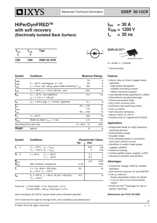
© 2000 IXYS All rights reserved1 - 1HiPerDynFRED TMwith soft recovery(Electrically Isolated Back Surface)Pulse test:x Pulse Width = 5 ms, Duty Cycle < 2.0 %y Pulse Width = 300 µs, Duty Cycle < 2.0 %Data according to IEC 60747 and per diode unless otherwise specifiedIXYS reserves the right to change limits, test conditions and dimensions. A = Anode, C = Cathode* Patent pendingISOPLUS 247TMAC CA FeaturesqSilicon chip on Direct-Copper-Bond substrate- High power dissipation - Isolated mounting surface - 2500V electrical isolationq Low cathode to tab capacitance (<25pF)q International standard package q Planar passivated chips q Very short recovery timeq Extremely low switching losses q Low I RM -valuesq Soft recovery behaviour q Epoxy meets UL 94V-0qIsolated and UL registered E153432ApplicationsqAntiparallel diode for high frequency switching devices q Antisaturation diode qSnubber diodeqFree wheeling diode in converters and motor control circuitsqRectifiers in switch mode power supplies (SMPS)q Inductive heatingq Uninterruptible power supplies (UPS)qUltrasonic cleaners and weldersAdvantagesqAvalanche voltage rated for reliable operationqSoft reverse recovery for low EMI/RFI qLow I RM reduces:-Power dissipation within the diode -Turn-on loss in the commutating switchqISOPLUS 247TM package for clip or spring mountingDimensions see IXYS CD 2000I FAV =30 A V RRM =1200 V t rr =20 nsV RSM V RRMTypeV V 12001200DSEP 30-12CR008Symbol ConditionsMaximum RatingsI FRMS70A I FAVM T C = 85°C; rectangular, d = 0.530A I FRM t P < 10 µs; rep. rating, pulse width limited by T VJM tbd A I FSM T VJ = 45°C; t p = 10 ms (50 Hz), sine 250A E AS T VJ = 25°C; non-repetitive 0.2mJ I AS = 1.3 A; L = 180 µHI ARV A = 1.25·V R typ.; f = 10 kHz; repetitive0.1A T VJ -55...+175°C T VJM175°C T stg -55...+150°C P tot T C = 25°C165W V ISOL 50/60 Hz RMS; I ISOL ≤ 1 mA 2.5kV Mounting force with clip10...50/2 (10)N/lb.Weighttypical6gSymbol ConditionsCharacteristic Values typ.max.I RxT VJ = 25°C V R = V RRM 250µA T VJ = 150°C V R = V RRM 2mA V F y I F = 30 A;T VJ = 150°C 3.1V T VJ = 25°C5.0V R thJC 0.9K/W R thCH with heatsink compound 0.25K/W t rr I F = 1 A; -di/dt = 200 A/µs;20nsV R = 30 V; T VJ = 25°CI RMV R = 100 V;I F = 50 A; -di F /dt = 100 A/µs 4.0AT VJ = 100°C元器件交易网。
ADC12化学成分

ADC12化学成分第一篇:ADC12化学成分ADC12化学成分ADC12含铝(Al)余量,铜(Cu)1.5~3.5,硅(Si)9.6~12.0,镁(Mg)≤0.3,锌(Zn)≤1.0,铁(Fe)≤0.9,锰(Mn)≤0.5,镍(Ni)≤0.5,锡(Sn)≤0.3ADC12是日本标准牌号Si10.5~11.5Fe0.3~0.6Cu3.0~3.5Mg0.2~0.3Mn0.3~0.5Zn0.6~0.9Ni0.2~0.5Sn≤0.3Al余量日本的ADC10及ADC12,基本上是用废旧铝再生的,日本还制订出废铝再生压铸铝合金的标准。
当前国内广泛应用压铸合金Y112,依据机械工业部的压铸合金标准,比较适宜于用废铝来熔炼,这无疑可缓解铝锭供不应求的矛盾。
日本的铝合金牌号,又称12号铝料,Al-Si-Cu系合金,是一种压铸铝合金,适合盖子、缸体类等,执行标准为:JIS H 5302-2000《铝合金压铸件》。
ADC12相当于中国国产的合金代号YL113,合金牌号是YZAlSi11Cu3,执行标嘉?篏B/T 15115-1994《压铸铝合金》(该标准2002年就列入国家标准修订计划,国标计划项目编号20021029-T-604,但不知为何至今尚未完成)。
美国合金牌号是383,执行标准为:ASTM B 85-03 Standard Specification fAluminum-Alloy Die Castings(可能还有比ASTM B 85-03更新的版本)ADC12化学成分ADC12含铝(Al)余量,铜(Cu)1.5~3.5,硅(Si)9.6~12.0,镁(Mg)≤0.3,锌(Zn)≤1.0,铁(Fe)≤0.9,锰(Mn)≤0.5,镍(Ni)≤0.5,锡(Sn)≤0.3可以用102,以前ADC12比102便宜,所以用ADC12,现在不可以,ADC12铝合金的溶解温度630°左右。
而6061/6063纯铝的溶解温度为730°左右,况且6061的压铸对模具的材质、产品的脱模斜度、原材料的温度、离型剂等要求比较严格。
BTB12-800中文资料

BTB12-800中⽂资料1/7BTA/BTB12 and T12 SeriesSNUBBERLESS ?, LOGIC LEVEL & STANDARD12A TRIAC SSeptember 2002 - Ed: 6AMAIN FEATURES:DESCRIPTIONAvailable either in through-hole or surface-mount packages, the BTA/BTB12 and T12 triac series is suitable for general purpose AC switching. They can be used as an ON/OFF function in applications such as static relays, heating regulation, induction motor starting circuits... or for phase control operation in light dimmers, motor speed controllers,...The snubberless versions (BTA/BTB...W and T12series) are specially recommended for use on inductive loads, thanks to their high commutation performances. Logic level versions are designed to interface directly with low power drivers such as microcontrollers. By using an internal ceramic pad, the BTA series provides voltage insulated tab (rated at 2500V RMS) complying with UL standards (File ref.: E81734)Symbol Value Unit I T(RMS)12A V DRM /V RRM 600 and 800V I GT (Q 1)5 to 50mAABSOLUTE MAXIMUM RATINGSSymbol ParameterValueUnit I T(RMS)RMS on-state current (full sine wave)D 2PAK/TO-220AB Tc = 105°C 12A TO-220AB Ins.Tc = 90°C I TSM Non repetitive surge peak on-state current (full cycle, Tj initial = 25°C) F = 50 Hz t = 20 ms 120AF = 60 Hzt = 16.7 ms126I 2t I 2t Value for fusingtp = 10 ms78A 2s dI/dtCritical rate of rise of on-state current I G = 2 x I GT , tr ≤ 100 nsF = 120 Hz Tj = 125°C 50A/µs V DSM /V RSM Non repetitive surge peak off-statevoltagetp = 10 ms Tj = 25°C V DRM /V RRM+ 100V I GM Peak gate currenttp = 20 µsTj = 125°C 4A P G(AV)Average gate power dissipation Tj = 125°C1W T stg T jStorage junction temperature range Operating junction temperature range- 40 to + 150- 40 to + 125°CBTA/BTB12 and T12 Series2/7ELECTRICAL CHARACTERISTICS (Tj = 25°C, unless otherwise specified)sSNUBBERLESS? and LOGIC LEVEL (3 Quadrants)sSTANDARD (4 Quadrants)STATIC CHARACTERISTICSNote 1: minimum IGT is guaranted at 5% of IGT max.Note 2: for both polarities of A2 referenced to A1 Symbol Test ConditionsQuadrantT12BTA/BTB12UnitT1235TW SW CW BW I GT (1)V D = 12 V R L = 30 ?I - II - III MAX.355103550mA V GT I - II - III MAX. 1.3V V GD V D = V DRM R L = 3.3 k ?Tj = 125°C I - II - III MIN.0.2V I H (2)I T = 100 mA MAX.3510153550mA I L I G = 1.2 I GTI - III MAX.5010255070mA II6015306080dV/dt (2)V D = 67 %V DRM gate open Tj = 125°CMIN.50020405001000V/µs (dI/dt)c (2)(dV/dt)c = 0.1 V/µs Tj = 125°CMIN.- 3.5 6.5--A/ms(dV/dt)c = 10 V/µs Tj = 125°C -1 2.9--Without snubber Tj = 125°C6.5-- 6.512Symbol Test ConditionsQuadrant BTA/BTB12UnitCB I GT (1)V D = 12 V R L = 30 ?I - II - III IV MAX.255050100mA V GT ALL MAX. 1.3V V GD V D = V DRM R L = 3.3 k ? Tj = 125°C ALL MIN.0.2V I H (2)I T = 500 mA MAX.2550mA I L I G = 1.2 I GTI - III - IVMAX.4050mA II80100dV/dt (2)V D = 67 %V DRM gate open Tj = 125°CMIN.200400V/µs (dV/dt)c (2)(dI/dt)c = 5.3 A/ms Tj = 125°CMIN.510V/µsSymbol Test ConditionsValue Unit V T (2)I TM = 17 A tp = 380 µs Tj = 25°C MAX. 1.55V V to (2)Threshold voltage Tj = 125°C MAX.0.85V R d (2)Dynamic resistance Tj = 125°C MAX.35m ?I DRM I RRMV DRM = V RRMTj = 25°C MAX.5µA Tj = 125°C1mABTA/BTB12 and T12 Series3/7THERMAL RESISTANCESS = Copper surface under tabPRODUCT SELECTORBTB: non insulated TO-220AB packageORDERING INFORMATIONSymbol ParameterValue Unit R th(j-c)Junction to case (AC)D 2PAK/TO-220AB 1.4°C/W TO-220AB Insulated2.3R th(j-a)Junction to ambientS = 1 cm 2D 2PAK45°C/WTO-220ABTO-220AB InsulatedPart NumberVoltage (xxx)Sensitivity Type Package 600 V 800 V BTA/BTB12-xxxB X X 50 mA Standard TO-220AB BTA/BTB12-xxxBW X X 50 mA Snubberless TO-220AB BTA/BTB12-xxxC X X 25 mA Standard TO-220AB BTA/BTB12-xxxCW X X 35 mA Snubberless TO-220AB BTA/BTB12-xxxSW X X 10 mA Logic level TO-220AB BTA/BTB12-xxxTW X X 5 mA Logic Level TO-220AB T1235-xxxGXX35 mASnubberlessD 2PAKBTA/BTB12 and T12 SeriesOTHER INFORMATIONNote: xxx = voltage, yy = sensitivity, z = typePart NumberMarkingWeight Base quantity Packing mode BTA/BTB12-xxxyz BTA/BTB12-xxxyz 2.3 g 250Bulk BTA/BTB12-xxxyzRGBTA/BTB12-xxxyz 2.3 g 50Tube T1235-xxxG T1235xxxG 1.5 g 50Tube T1235-xxxG-TRT1235xxxG1.5 g1000Tape & reelFig. 1: Maximum power dissipation versus RMSon-state current (full cycle).Fig. 2-1: RMS on-state current versus case temperature (full cycle).Fig. 2-2: RMS on-state current versus ambient temperature (printed circuit board FR4, copper thickness: 35µm),full cycle. Fig. 3: Relative variation of thermal impedance versus pulse duration.BTA/BTB12 and T12 Series5/7Fig. 4: On-state characteristics (maximum values).Fig. 5: Surge peak on-state current versus number of cycles.Fig. 6: Non-repetitive surge peak on-state current for a sinusoidal pulse with width tp <10ms, and corresponding value of I2t. Fig. 7: Relative variation of gate trigger current,holding current and latching current versus junction temperature (typical values).Fig. 8-1: Relative variation of critical rate of decrease of main current versus (dV/dt)c (typical values) (BW/CW/T1235). Fig. 8-2: Relative variation of critical rate of decrease of main current versus (dV/dt)c (typical values) (TW).BTA/BTB12 and T12 Series6/7Fig. 9: Relative variation of critical rate of decrease of main current versus junction temperature.Fig. 10: D2PAK Thermal resistance junction to ambient versus copper surface under tab (printed circuit board FR4, copper thickness: 35µm).PACKAGE MECHANICAL DATAFOOTPRINT DIMENSIONS (in millimeters)BTA/BTB12 and T12 Series PACKAGE MECHANICAL DATAInformation furnished is believed to be accurate and reliable. However, STMicroelectronics assumes no responsibility for the consequences of use of such information nor for any infringement of patents or other rights of third parties which may result from its use. No license is granted by implication or otherwise under any patent or patent rights of STMicroelectronics. Specifications mentioned in this publication are subject to change without notice. This publication supersedes and replaces all information previously supplied. STMicroelectronics products are not authorized for use as critical components in life support devices or systems without express written approval of STMicroelectronics.The ST logo is a registered trademark of STMicroelectronics2002 STMicroelectronics - Printed in Italy - All Rights ReservedSTMicroelectronics GROUP OF COMPANIESAustralia - Brazil - Canada - China - Finland - France - GermanyHong Kong - India - Isreal - Italy - Japan - Malaysia - Malta - Morocco - SingaporeSpain - Sweden - Switzerland - United Kingdom - United States./doc/9a8939ddb9f3f90f76c61b94.html7/7。
PM8微波式浓度变送器综述
PM8微波式浓度变送器综述一、微波浓度变送器介绍我公司8#机在线浓度测量使用的变送器主要有三种,一种是SMART-PULP (静刀式)浓度变送器、KajaaniMCAi(微波式)浓度变送器(8台)、SMARTLC(光学式)浓度变送器,其中配浆系统用的都是微波式浓度变送器。
下面介绍微波式浓度变送器。
1、测量原理:微波式浓度变送器的的测量原理是建立于微波的传播速度和浆的浓度成比例关系的基础上的。
公式为:v=c / dv:微波的传播速度c:光在真空中的传播速度d:介质的电导常数根据这一个公式可以看出微波在水中的传播速度比在木纤维中要慢很多,因此木纤维的数量(浓度)可以通过测量微波在浆料中的传播时间而得到,也就是微波在浓变的发射天线和接受天线之间传播的时间。
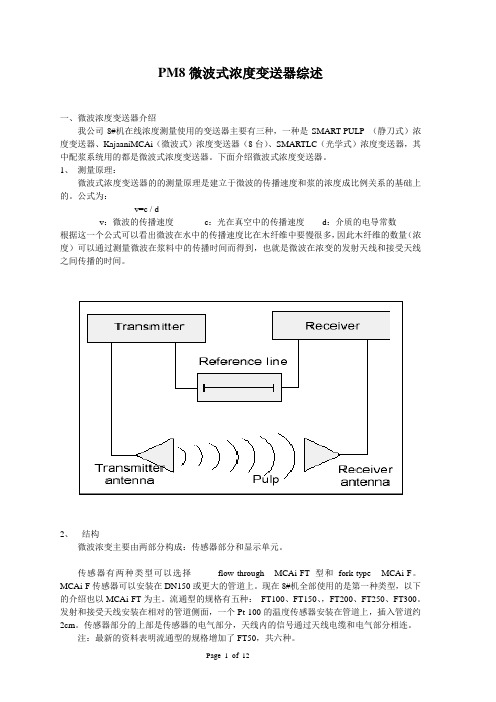
2、结构微波浓变主要由两部分构成:传感器部分和显示单元。
传感器有两种类型可以选择---------flow-through MCAi-FT 型和fork-type MCAi-F。
MCAi-F传感器可以安装在DN150或更大的管道上。
现在8#机全部使用的是第一种类型,以下的介绍也以MCAi-FT为主。
流通型的规格有五种:FT100、FT150、,FT200、FT250、FT300。
发射和接受天线安装在相对的管道侧面,一个Pt-100的温度传感器安装在管道上,插入管道约2cm。
传感器部分的上部是传感器的电气部分,天线内的信号通过天线电缆和电气部分相连。
注:最新的资料表明流通型的规格增加了FT50,共六种。
打开电气部分的顶盖,是接线端子,指示灯,复位键等。
打开内盖,其内部三部分组成,微波发生模块、主板、处理器板。
接线端子的接线示意图见下:复位键的作用与使用手持终端的复位作用一样,会将所有的数据全部清空,恢复成默认状态应该尽量避免使用。
复位时,同时按下RESET和ABORT键3秒以上。
显示单元通过厂家配置的专用电缆与传感器部分通讯并提供24vDC电源,显示信息。
- 1、下载文档前请自行甄别文档内容的完整性,平台不提供额外的编辑、内容补充、找答案等附加服务。
- 2、"仅部分预览"的文档,不可在线预览部分如存在完整性等问题,可反馈申请退款(可完整预览的文档不适用该条件!)。
- 3、如文档侵犯您的权益,请联系客服反馈,我们会尽快为您处理(人工客服工作时间:9:00-18:30)。
CR8PM-12
Thyristor
Medium Power Use
REJ03G0359-0100
Rev.1.00
Aug.20.2004 Features
•I T (AV) : 8 A •V DRM : 600 V •I GT : 15 mA •Viso : 1500 V •Insulated Type
•Planar Passivation Type
•UL Recognized : Yellow Card No. E223904
File No. E80271
Outline
Applications
Switching mode power supply, regulator for autocycle, motor control, heater control, and other general purpose control applications
Maximum Ratings
Voltage class
Parameter Symbol
12
Unit Repetitive peak reverse voltage V RRM600V
Non-repetitive peak reverse voltage V RSM720V
DC reverse voltage V R(DC)480V Repetitive peak off-state voltage V DRM600V
DC off-state voltage V D(DC)480V
Parameter Symbol Ratings Unit Conditions
RMS on-state current I T (RMS)12.6A
Average on-state current I T (AV)8A Commercial frequency, sine half wave
180° conduction, Tc = 81°C
Surge on-state current I TSM120A60Hz sine half wave 1 full cycle,
peak value, non-repetitive
I2t for fusing I2t60A2s Value corresponding to 1 cycle of half
wave 60Hz, surge on-state current Peak gate power dissipation P GM5W
Average gate power dissipation P G (AV)0.5W
Peak gate forward voltage V FGM6V
Peak gate reverse voltage V RGM10V
Peak gate forward current I FGM2A
Junction temperature Tj– 40 to +125°C
Storage temperature Tstg– 40 to +125°C
Mass— 2.0g Typical value
Isolation voltage Viso1500V Ta = 25°C, AC 1 minute,
each terminal to case
Electrical Characteristics
Rated value
Unit Test conditions Parameter Symbol
Min.Typ.Max.
Repetitive peak reverse current I RRM—— 2.0mA Tj = 125°C, V RRM applied Repetitive peak off-state current I DRM—— 2.0mA Tj = 125°C, V DRM applied On-state voltage V TM—— 1.4V Tc = 25°C, I TM = 25 A,
instantaneous value
Gate trigger voltage V GT—— 1.0V Tj = 25°C, V D = 6 V, I T = 1 A Gate non-trigger voltage V GD0.2——V Tj = 125°C, V D = 1/2 V DRM Gate trigger current I GT——15mA Tj = 25°C, V D = 6 V, I T = 1 A Holding current I H—15—mA Tj = 25°C, V D = 12 V Thermal resistance R th (j-c)—— 3.7°C/W Junction to case Note1 Notes: 1.The contact thermal resistance R th (c-f) in case of greasing is 0.5°C/W.
Performance Curves
Package Dimensions
Order Code
Lead form Standard packing Quantity Standard order code Standard order code example
Straight type Vinyl sack100Type name +A CR8PM-12A Lead form Plastic Magazine (Tube)50Type name +A – Lead forming code CR8PM-12A-A8 Note :Please confirm the specification about the shipping in detail.
RENESAS SALES OFFICES
Renesas Technology America, Inc.
450 Holger Way, San Jose, CA 95134-1368, U.S.A
Tel: <1> (408) 382-7500 Fax: <1> (408) 382-7501
Renesas Technology Europe Limited.
Dukes Meadow, Millboard Road, Bourne End, Buckinghamshire, SL8 5FH, United Kingdom
Tel: <44> (1628) 585 100, Fax: <44> (1628) 585 900
Renesas Technology Europe GmbH
Dornacher Str. 3, D-85622 Feldkirchen, Germany
Tel: <49> (89) 380 70 0, Fax: <49> (89) 929 30 11
Renesas Technology Hong Kong Ltd.
7/F., North Tower, World Finance Centre, Harbour City, Canton Road, Hong Kong
Tel: <852> 2265-6688, Fax: <852> 2375-6836
Renesas Technology Taiwan Co., Ltd.
FL 10, #99, Fu-Hsing N. Rd., Taipei, Taiwan
Tel: <886> (2) 2715-2888, Fax: <886> (2) 2713-2999
Renesas Technology (Shanghai) Co., Ltd.
26/F., Ruijin Building, No.205 Maoming Road (S), Shanghai 200020, China
Tel: <86> (21) 6472-1001, Fax: <86> (21) 6415-2952
Renesas Technology Singapore Pte. Ltd.
1, Harbour Front Avenue, #06-10, Keppel Bay Tower, Singapore 098632
Tel: <65> 6213-0200, Fax: <65> 6278-8001
© 2004. Renesas Technology Corp., All rights reserved. Printed in Japan.
Colophon .1.0。