SIM800_蓝牙调试笔记
sim800c

sim800c1. 简介SIM800C是一款功能强大的GSM/GPRS模块,适用于各种无线通信应用。
它支持全球四个频段,可用于数据传输、语音通信和短信服务。
本文将介绍SIM800C的特性、使用方法和常见问题解决方案。
2. 特性•支持四个频段:850/900/1800/1900 MHz•支持GSM、GPRS、TCP/UDP等协议•支持数据、语音和短信传输•支持SIM卡热插拔•内置SIM卡接口和天线接口•支持电源电压范围:3.4V - 4.4V•尺寸小巧便于集成3. 使用方法要使用SIM800C模块,您需要完成以下步骤:3.1. 连接硬件首先,将SIM800C模块与您的主控设备进行连接。
将模块的VCC引脚连接到主控的电源正极,将GND引脚连接到主控的电源地。
然后,将模块的TXD引脚连接到主控的串口发送引脚,将RXD引脚连接到主控的串口接收引脚,确保电平匹配。
3.2. 配置串口在主控设备上,配置串口参数以与SIM800C进行通信。
设置波特率为通信速率,并确保其中一个数据位停止位的选择正常。
3.3. 初始化模块初始化SIM800C模块以准备进行通信。
通过向模块发送AT指令,检查是否收到OK响应。
如果响应正常,表示SIM800C模块已成功初始化。
3.4. 发送指令通过向SIM800C模块发送AT指令,您可以执行各种操作,如发送短信、拨打电话、建立网络连接等。
在每个指令后面加上回车符和换行符,以确保指令能够正确解析。
3.5. 处理响应SIM800C模块会对每个指令作出相应的响应。
您需要根据响应结果来判断操作是否成功。
响应以OK或ERROR等关键字开头,解析响应以获取操作的结果。
4. 常见问题解决方案4.1. 无法连接到网络如果您无法连接到网络,请检查以下几点:•确保SIM卡已插入SIM800C模块并且正常工作。
•确保SIM卡具有有效的套餐和足够的余额。
•检查SIM卡是否正确插入模块,并且天线是否连接良好。
•检查SIM800C模块的电源供应是否正常。
SIM800 Bluetooth applocation
SIM800 Series _Bluetooth_ Application Note_V1.02Document Title SIM800 Series_Bluetooth_Application NoteVersion 1.02Date 2014-06-30Status ReleaseDocument Control ID SIM800 Series_Bluetooth_Application Note_V1.02General NotesSimcom offers this information as a service to its customers, to support application and engineering efforts that use the products designed by Simcom. The information provided is based upon requirements specifically provided to Simcom by the customers. Simcom has not undertaken any independent search for additional relevant information, including any information that may be in the customer’s possession. Furthermore, system validation of this product designed by SIMCOM within a larger electronic system remains the responsibility of the customer or the customer’s system integrator. All specifications supplied herein are subject to change.CopyrightThis document contains proprietary technical information which is the property of SIMCOM Limited., copying of this document and giving it to others and the using or communication of the contents thereof, are forbidden without express authority. Offenders are liable to the payment of damages. All rights reserved in the event of grant of a patent or the registration of a utility model or design. All specification supplied herein are subject to change without notice at any time.Copyright © SIMCom Wireless Solutions Ltd. 2014ContentVersion History (5)1.Bluetooth Function (6)1.1. Bluetooth Introduction (6)1.2. Bluetooth Profile (6)1.3. Bluetooth Device Address (6)1.4. AT Interface for Bluetooth Function (6)2.AT Command (8)2.1. AT+BTHOST Inquiry and set host device name (8)2.2. AT+BTSTATUS Inquiry current BT device status (9)2.3. AT+BTPOWER Power on/off BT radio (10)2.4. AT+BTPAIR Pair BT device (10)2.5. AT+BTUNPAIR Unpair BT device (12)2.6. AT+BTSCAN Scan surrounding BT device (12)2.7. AT+BTCONNECT Connect paired BT device (13)2.8. AT+BTDISCONN Disconnect BT connection (13)2.9. AT+BTGETPROF Get profile provided by paired device (14)2.10. AT+BTACPT Accept connecting request (14)2.11. AT+BTOPPACPT Accept OPP service (15)2.12. AT+BTOPPPUSH Push OPP object to paired device (16)2.13. AT+BTSPPGET Get data based on SPP service (16)2.14. AT+BTSPPSEND Send data based on SPP service (17)2.15. AT+BTATA Answer incoming call (18)2.16. AT+BTATDL Redial last number (18)2.17. AT+BTATH Hung up voice call (19)2.18. AT+BTVGS Configure voice volume (19)2.19. AT+BTVGM Configure MIC gain level (19)2.20. AT+BTATD Dial voice call (20)2.21. AT+BTRSSI Get RSSI of connected BT device (20)2.22. AT+BTVTS Send DTMF tone (21)2.23. AT+BTCIND Get status of smartphone (21)2.24. AT+BTCLCC Get call’s status of smartphone (22)2.25. AT+BTPBSYNC Sync phonebook from remote by BT (23)2.26. AT+BTPBF Find name or number from remote by BT (25)2.27. AT+BTA VRCOP A VRCP operation (27)2.28. AT+BTVIS Set visibility of BT (27)2.29. AT+BTSPPCFG SPP configuration (28)2.30. AT+BTPAIRCFG Set BT pairing mode (28)2.31. AT+CPBFEX Find name or number in module phonebook (29)2.32. AT+BTRING Control ring playing transferred from phone (30)3.CME Error Code (31)4.Examples (33)4.1. Accept request from other BT device (33)4.2. Send pairing request to other BT device (33)4.3. Get the profile provided by paired device (34)4.4. Connect service (35)4.5. Accept file from paired device (35)4.6. Send file to other paired BT device (35)4.7. Create SPP’s link as a client (35)4.8. SPP’s link be create as a server (36)4.9. Configurate SPP (36)4.10. Send data as a SPP’s client (37)4.11. As a SPP’s server worked in AT mode (37)4.12. As a SPP’s server worked in APP mode (38)4.13. Sync phonebook from remote by BT (39)4.14. Find name or number from remote by BT (39)4.15. Play music and so on by A VRCP (40)4.16. Add phonebook records to ME or SM phonebook from VCARD file (41)4.17. Set BT pairing mode (42)5.Differences between bluetooth version and the standard Version (44)5.1. ATD<str> (44)5.2. AT+CPBF (44)5.3. AT+CMUX (44)5.4. AT+CNUM (44)5.5. AT+CMGS (45)5.6. AT+CMSS (45)5.7. AT+CPMS (45)5.8. AT+CHFA (45)5.9. TTS function (45)Appendix (46)A. Reference (46)B. Profile (46)C. Glossary and Abbreviation (47)Version History DateVersion Description Author 2013-11-071.00 Original Ping Zhang Chapter 1.4, Add “power-saving mode” descriptionChapter 2.6, AT+BTSCAN add <rssi> parameterChapter 2.13, Modify AT+BTSPPGET parameterChapter 2.14, Modify AT+BTSPPSEND parameterChapter 2.22, Add AT+BTVTS commandChapter 2.23, Add AT+BTCIND commandChapter 2.24, Add AT+BTCLCC commandChapter 2.25, Add AT+BTPBSYNC commandChapter 2.26, Add AT+BTPBF commandChapter 2.27, Add AT+BTA VRCOP commandChapter 2.28, Add AT+BTVIS commandChapter 2.29, Add AT+BTSPPCFG commandChapter 2.30, Add AT+BTPAIRCFG commandChapter 3, Add Error Code 1051,1056--1058,10602014-03-26 1.01 Chapter 4, Add 4.7----4.17Ping Zhang Chapter 2.13, Modify AT+BTSPPGET and <command> descriptionChapter 2.31,Add AT+CPBFEX commandChapter 2.32,Add AT+BTRING commandChapter 4.12,Modify demo2014-06-30 1.02 Chapter 5, AddPing ZhangScopeThis document describes how to use the AT command about Bluetooth and some applicationnote.The document can apply to SIM800, SIM800-WB64, SIM808, SIM800H Series version withBluetooth fuction.1.Bluetooth Function1.1.Bluetooth IntroductionBluetooth is a wireless technology standard for exchanging data over short distances (usingshort-wavelength radio transmissions in the ISM band from 2400–2480 MHz) from fixed and mobile devices, creating prsonal area networks (PANs) with high levels of security.Bluetooth was standardized as IEEE 802.15.11.2.Bluetooth ProfileTo use Bluetooth wireless technology, a device has to be able to interpret certain Bluetooth profiles, which are definitions of possible applications and specify general behaviors that Bluetooth enabled devices use to communicate with other Bluetooth devices. These profiles include settings to parametrize and to control the communication from start. Adherence to profiles saves the time for transmitting the parameters anew before the bi-directional link becomes effective. There are a wide range of Bluetooth profiles that describe many different types of applications or use cases for devices.Besides of all profiles, there have four basic ones, they are GAP/SDAP/SPP/GOEP Profile.1.3.Bluetooth Device AddressThe Bluetooth device address stores the network address of a Bluetooth–enabled device. It is used to identify a particular device during operations such as connecting to, pairing with, or activating the device.A Bluetooth–enabled device address is a unique, 48 bits address containing the following three fields:•LAP field: lower part of the address containing 24 bits.•UAP field: upper part of the address containing 8 bits.•NAP field: non–significant part of the address containing 16 bits.The LAP and the UAP represent the significant address part (SAP) of the Bluetooth device address.1.4.AT Interface for Bluetooth FunctionAs module solution, we provide series of AT interface to operate Bluetooth function, including pairing, bonding, pushing or receiving file.Also including interface for SPP service, which could communicate between Bluetooth device and others via serial port.When the module as a Bluetooth headset role, we provide a set of AT commands to control theremote smart phones, such as phone calls, turn on or hang up calls and so on.By default, the module operates in power-saving mode, which means that the module can besimultaneously connected to a Bluetooth device. When the module to establish a connection with adevice, other devices can not be scanned into the module, the module can not get Profile, will notbe able to establish new connections and modules. If the customer's application scenario, themodule needs to be multiple Bluetooth devices (currently up to three) connection, you need to usethe AT + BTSPPCFG = 1 command to turn off the power saving mode. It should be noted that thepower saving mode does not affect the module initiative to connect to other Bluetooth devices.2. AT Command CommandDescription AT+BTHOST Inquiry and set host device name AT+BTSTATUSInquiry current BT device status AT+BTPOWERPower on or power off BT radio AT+BTPAIRPair BT deviceAT+BTSCANScan surrounding BT device AT+BTUNPAIRUnpair BT deviceAT+BTCONNECTConnect paired BT deviceAT+BTDISCONNDisconnect BT device AT+BTGETPROFGet profile provided by paired deviceAT+BTACPTAccept connecting requestAT+BTOPPACPTAccept OPP serviceAT+BTOPPPUSHPush OPP object to paired deviceAT+BTSPPSENDSend data based on SPP service AT+BTSPPGETGet data based on SPP service AT+BTATAAnswer incoming call AT+BTATDLRedial last number AT+BTATHHung up voice call AT+BTVGSConfigure voice volume AT+BTVGMConfigure MIC volume AT+BTATDDial up a voice call AT+BTRSSIGet RSSI of connected device AT+BTVTSSend DTMF tone AT+BTCINDGet status of smartphone AT+BTCLCCGet call’s status of smartphone AT+BTPBSYNCSync phonebook from remote by BT AT+BTPBFFind name or number from remote by BT AT+BTA VRCOPA VRCP Operation AT+BTVISSet visibility of BT AT+BTSPPCFGSPP’s config AT+BTPAIRCFGSet BT pairing mode AT+CPBFEXFind name or number in module phonebook AT+BTRINGControl ring playing transferered from phone2.1. AT+BTHOST Inquiry and set host device nameAT+BTHOST Inquiry and set host device nameResponse+BTHOST: (1-18)OKTest commandAT+BTHOST=?ParametersSee Write CommandResponse+BTHOST: <name>, <address>OKRead commandAT+BTHOST?ParametersSee Write CommandResponseOKWrite commandAT+BTHOST=<name> Parameters<name> device name<address> device addressNote Max length of <name> is 18 bytes,and display in UTF-8 code.2.2.AT+BTSTATUS Inquiry current BT device statusAT+BTSTATUS Inquiry current BT device statusResponseOKTest CommandAT+BTSTATUS=? ParametersSee Read CommandResponseIf unpaired before:+BTSTATUS: <status>If paired before but unconnected:+BTSTATUS: <status>P: <paired id>, <name> <address>If paired and connected:+BTSTATUS: <status>P: <paired id>, <name> <address>C: <connected id>,<name>,<address>,<profile name>OKRead CommandAT+BTSTATUS?Parameters<status> 0 Initial1Disactivating2Activating5 Idle6 Scanning7Inquiry_Res_Ind8 stopping scanning9Bonding12Connecting13Unpairing14 Deleting paired device15 Deleting all paired device16Disconnecting19 Pairing confirm while passive pairing20 Waiting for remote confirm while passive pairing25Acceptingconnection26 SDC Refreshing29 Setting host name30 Releasing all connection31 Releasing connection36Activatingservice<paired id> paired device ID<connected id> connected device ID<name> device name<address> device address<profile name> profileNote Max length of <name> is 18 bytes, 18 bytes in UTF-8 code2.3.AT+BTPOWER Power on/off BT radioAT+BTPOWER Power on/off BT radioResponse+BTPOWER: (list of supported <n>s)OKTest CommandAT+BTPOWER=?ParametersSee Write CommandResponseOKWrite CommandAT+BTPOWER=<n>parameter<n> 0 power off BT radio1 power on BT radioNote After power off BT radio, should wait 25s at least to re-power on BTradio.2.4.AT+BTPAIR Pair BT deviceAT+BTPAIR Pair BT deviceResponse +BTPAIR: 0,(list of supported <device ID>s )+BTPAIR: 1,(list of supported <confirm>s )+BTPAIR: 2,( length of supported <passkey>s )OKTest CommandAT+BTPAIR=? ParametersSee Write CommandResponse OK If digital key exchanged +BTPAIRING: <name>,<address>,<passcode> If passkey exchanged: +BTPAIRING: <name>,<address> If passive mode with succees: +BTPAIR: <id>,<name>,<address> If passive mode with failure: +BTPAIR: 0 Parameters <device ID> BT device ID <confirm> 1 accept0 reject<passkey> passkey, length is (4-16)<id> 0 paired failed>=1 paired deivce ID<name > BT device name<address > BT device address<passcode> Digital passwordWrite Command1) activeAT+BTPAIR=0,<device ID>2) passive withdigital key requestAT+BTPAIR=1,<confirm>3) passive withpasskey requestAT+BTPAIR=2,<passkey> URCIf there is incoming request:+BTPAIRING: <name>,<address>,<passcode>or+BTPAIRING: <name>,<address>Parameters<name > device name<address > device address<passcode> digital passwordNote1. Max length of <name> is 18 bytes, 18 bytes in UTF-8 code2. Pairing timeout is around 15s each side2.5.AT+BTUNPAIR Unpair BT deviceAT+BTUNPAIR Unpair BT deviceResponse+BTUNPAIR: (list of supported <device ID>s)OKTest CommandAT+BTUNPAIR=?ParameterSee Write CommandResponseOKWrite CommandAT+BTUNPAIR=<device ID>Parameter<device ID> Paired Device ID.0 delete all the paired device1 delete the the paired device corresponding to ID2.6.AT+BTSCAN Scan surrounding BT deviceAT+BTSCAN Scan surrounding BT deviceResponse+BTSCAN: (list of supported <switch>s), (list of supported <Timer>s)OKTest CommandAT+BTSCAN=?ParametersSee Write CommandResponseOKIf BT device scanned:+BTSCAN: <status>,<device ID>,<name>,<address>,<rssi>If terminate:+BTSCAN: <status>Wrtie CommandAT+BTSCAN=<switch>[,<Timer>]Parameters<switch> 1 start0 stop<status> 0 BT device found1 scanning finished2 scanning stop3 scanning failed<Timer> scanning time 10-60s<device ID> BT device ID scanned<name> BT device name<address> BT device address<rssi> -127…0 RSSI value of BT deviceNote 1.Max length of <name> is 18 bytes, 18 bytes in UTF-8 code2.If <timer> ommited, the default value is 30s2.7.AT+BTCONNECT Connect paired BT deviceAT+BTCONNECT Connect paired BT deviceResponse+BTCONNECT: (list of supported <device ID>s), (list of supported<profile ID>s)OKTest CommandAT+BTCONNECT=?ParametersSee Write CommandResponseOKIf OK:+BTCONNECT: <id>,<name>,<address>,<profile name>If failed:+BTCONNECT: 0Write CommandAT+BTCONNECT=<deviceID>,<profile ID>Parameters<device ID> ID of paired BT device< profile ID> BT profile ID<id> ID of connected BT device<name> BT device name<address> BT device adress<profile name> BT device service nameNote 1. Max length of <name> is 18 bytes, 18 bytes in UTF-8 code2. Connection timeout is around 20s3. if incoming request, there will be URC+BTCONNECING: <address>,<profile name>2.8.AT+BTDISCONN Disconnect BT connectionAT+BTDISCONN Disconnect BT connectionResponse+BTDISCONN: (list of supported <device ID>s)OKTest CommandAT+BTDISCONN=?ParametersSee Write CommandWrite CommandAT+BTDISCONN=<device ID>ResponseOK+BTDISCONN: <name>,<address>,<profile name>Parameters<device ID> connected device ID<name > device name<address > devie address<profile name> profile serviceNote1. Max length of <name> is 18 bytes, 18 bytes in UTF-8 code 2. If disconnected by remote, there still be URC: +BTDISCONN2.9. AT+BTGETPROF Get profile provided by paired deviceAT+BTGETPROF Get profile provided by paired deviceResponse +BTGETPROF: (list of supported <device ID>s )OKTest CommandAT+BTGETPROF=? ParametersSee Write CommandResponse OK+BTGETPROF: <profile ID>,<profile name>Write CommandAT+BTGETPROF=<device ID> Parameters<device ID> Paired Device ID<profile ID> profile ID<profile name> profile name2.10. AT+BTACPT Accept connecting requestAT+BTACPT Accept connecting requestResponse +BTACPT: (list of supported <confirm>s )OKTest CommandAT+BTACPT=?Response OKIf connected successfully, then will report:+BTCONNECT: <id>,<name>,<address>,<profile name>If connecting failed:+ BTDISCONN: <name>,<address>,<profile name>Write CommandAT+BTACPT=<confirm> Parameters<confirm> 1 accept0 reject<id> >0 connected device ID<name > device name<address > device address<profile name> profile nameURCIf incoming connecting request:+BTCONNECTING: <address>, <profile name>Parameters<address > device address<profile name> profile nameNoteMax length of <name> is 18 bytes, 18 bytes in UTF-8 code2.11. AT+BTOPPACPT Accept OPP serviceAT+BTOPPACPT Accept OPP serviceResponse +BTOPPACPT: (list of supported <confirm>s ),(list of supported<drv >)OKTest CommandAT+BTOPPACPT=?Response OK +BTOPPPUSH: <status>Parameters<confirm> 1 Accept0 Reject<drv> 0 internal flash memory1 external memory card<status> 0 failed1 successfulWrite CommandAT+BTOPPACPT=<confirm>[,<drv>] URC:If there has an incoming opp file, there will be a URC report.+BTOPPPUSHING: <name>, <file name>Parameters<name > device name<file name> file nameNote 1. Max length of <name> is 18 bytes, 18 bytes in UTF-8 code2.File is stored in path: C:\User\BtReceived\ for internal memory card,D:\BtReceived\ for external memory card. At the first time to use SDcard, customer must execute “AT+SD2PCM=0” and “AT&W”, thenreboot the module.2.12.AT+BTOPPPUSH Push OPP object to paired deviceAT+BTOPPPUSH Push OPP object to paired deviceResponse+BTOPPPUSH: (list of supported <device ID>s), (length of supported<string>s)OKTest CommandAT+BTOPPPUSH=?ParametersSee Write CommandResponseOK+BTOPPPUSH: <para>Write CommandAT+BTOPPPUSH=<device ID>,<string>Parameters<device ID> Paired Device ID<string> file name include complete path, lenght(4-259)<para> 0 Send failed1 Send successfully2ServerissueNote2.13.AT+BTSPPGET Get data based on SPP serviceAT+BTSPPGET Get data based on SPP serviceResponse+BTSPPGET: (list of supported <command>s), (list of supported<connectId>), (list of supported <reqLength>s), (list of supported<showWithHex>s)OKTest CommandAT+BTSPPGET=?ParametersSee Write CommandResponse+BTSPPGET: <command>OKRead CommandAT+BTSPPGET?ParametersSee Write CommandResponseOKorERRORIf command value is 2,return:+BTSPPGET: <connectId>,<cnfLen1>OKIf command value is 3,return:+BTSPPGET: <connectId>,<cnfLen1>[,<data string>]OKWrite Command1).IfAT+BTSPPCFG=”MC”,2 response1(Enablemulti-connect)AT+BTSPPGET=<command>[,<connectId>][,<reqLength>][,<showWithHex>]2).IfAT+BTSPPCFG=”MC”,2 response0(Disablemulti-connect)AT+BTSPPGET=<command>[,<reqLength>][,<showWithHex>]Parameters<command> 0 Auto mode. Data will be output in decimal system.1 Manual mode. There will be an indication when firstpackage arrives.2 Inquiry data length in manual mode.If multi-connectenabled,this command need parameter <connectId>.3 Getting data in manual mode. If multi-connectenabled,this command need parameter <connectId>.You can inputparams of <reqLength> and <showWithHex> when you need.<reqLength> 1-1024 , the length of data requested, only valid in manualmode<showWithHex> 1, displayed in hex, only valid in manual mode<connectId> connection`s ID<cnfLen1> 0-1024, character length<data string> string printedNote URCWhen the module receives data by SPP,there will be URC report:1. Auto mode+BTSPPDATA: <connectId>,<cnfLen2>,<data string>2. Manual mode+BTSPPMAN: <connectId>Parameter<cnfLen2> 1-1024, length of printed character2.14.AT+BTSPPSEND Send data based on SPP serviceAT+BTSPPSEND Send data based on SPP serviceWrite Command1).IfResponse>If successful, SEND OK If failed, SEND FAIL Or if this connectId is not allowed to send data, ERROR AT+BTSPPCFG=”MC”,2 response1(Enablemulti-connect)AT+BTSPPSEND=<connectId>,<length>2).IfAT+BTSPPCFG=”MC”,2 response0(Disablemulti-connect)AT+BTSPPSEND=<length>Parameters <connectId > connection`s ID.If disable multi-connection, this param is no need. <length> 1-1024, the length of data will be sent. When the length of inputing data is up to <length> specified, the package will be sent out automatically. Press ESC key will quit the process. Response > If successful, SEND OKOr failed,SEND FAILOr if this connectId is not allowed to send data,ERRORExecuteCommandAT+BTSPPSEND 1.If multi-connection function is enabled, this command will be disabled.2.In this mode, <Ctrl+z> will send the package immediately, and ESC will quit the process.2.15. AT+BTATA Answer incoming callAT+BTATA Answer incoming callResponse OKExecute CommandAT+BTATA URCIf there is incoming Call on remote phone, will report below:BTRINGNoteWhen module connected with smartphone as an earphone,if here comes incoming call,the call would be answered through this command2.16. AT+BTATDL Redial last numberAT+BTATDL Redial last numberExecute CommandAT+BTATDLResponse OK Note When module connected with smartphone as an earphone,would rediallast number through this command2.17. AT+BTATH Hung up voice callAT+BTATH Hung up voice callExecute CommandAT+BTATHResponse OK NoteWhen module connected with smartphone as an earphone, the incoming call would be hung up through this command2.18. AT+BTVGS Configure voice volumeAT+BTVGS Configure voice volumeResponse +BTVGS: (<gain> range )OKTest CommandAT+BTVGS=? Module is Earphone modeResponse +BTVGS: <gain>OKRead CommnadAT+BTVGS?Response OK Write CommandAT+BTVGS=<gain> Parameter<gain > volumeThis command is used configure call volume when the module isconnected with smartphone as an earphoneNoteFor some smartphone,after connected with BT earphone,the current callvolume may not be transmitted to earphone,thus the return value of theread command may be 0.But after setting once,the value would be correct.2.19. AT+BTVGM Configure MIC gain levelAT+BTVGM Configure MIC gain levelResponse +BTVGM: (<gain> range )OKTest CommandAT+BTVGM=?Read CommandAT+BTVGM? Response +BTVGM: <gain>OKResponse OK Write CommandAT+BTVGM=<gain> Parameter<gain > MIC gain levelThis command is used set MIC volume when the module is connectedwith smartphone as an earphoneNoteFor some smartphone,after connected with BT earphone,the current MICvolume may not be transmitted to earphone,thus the return value of theread command may be 0.But after setting once,the value would be correct. 2.20. AT+BTATD Dial voice callAT+BTATD Dial voice callResponse +BTATD: (<number> length range )OKTest CommandAT+BTATD=?Response OK Write CommandAT+BTATD=<number> Parameter<number > phone numberModule as earphone connected to smartphone, this command could makean outgoing callNote2.21. AT+BTRSSI Get RSSI of connected BT deviceAT+BTRSSI Get RSSI of connected BT deviceResponse +BTRSSI: (list of supported <device ID>s )OKTest CommandAT+BTRSSI=?Response +BTRSSI: <rssi>OKWrite CommandAT+BTRSSI=<device ID> Parameters<device ID> Connected Device ID<rssi> -127…0 RSSI value of BT deviceNote RSSI value is negative, the smaller value represents the worse signal2.22.AT+BTVTS Send DTMF toneAT+BTVTS Send DTMF toneResponse+BTVTS: (<dtmf>’s cope)OKTest CommandAT+BTVTS=?ResponseOKWrite CommandAT+BTVTS=<dtmf> Parameter<dtmf> DTMF toneNote When module connected with smartphone as an earphone,would send DTMF tone through this command2.23.AT+BTCIND Get status of smartphoneAT+BTCIND Get status of smartphoneResponse+BTCIND: (0,1)OKTest CommandAT+BTCIND=?ResponseOKParameter<mode> 1 auto report open0 auto report closeWrite CommandAT+BTCIND=<mode>Unsolicited Result CodeWhen <mode>=1, any changed in<service>,<call>,<call_setup>,<held>,<signal>,<roam>,<battchg> , anunsolicited result code is returnd:+BTCIND:1,<service>,<call>,<call_setup>,<held>,<signal>,<roam>,<battchg>Read CommandAT+BTCIND?Response+BTCIND:<mode>,<service>,<call>,<call_setup>,<held>,<signal>,<roam>,<battchg>OKParameters<service> 0 no net service1 net service is normal<call> 0not active1 active<call_setup> 0 set up complete1 incoming call2 outgoing call3 remote alert<held> 0 no held call1 active calls be placed or switched2 active calls be palced and no active call<signal> 0..5 net work signal<roam> 0 no roaming1 in roaming<battchg> 0..5 power levelNote When module connected with smartphone as an earphone, these statuses can be getted.2.24.AT+BTCLCC Get call’s status of smartphoneAT+BTCLCC Get call’s status of smartphoneResponseOKTest CommandAT+BTCLCC=?ResponseOKWhen call is active:+BTCLCC: <index>,<dir>,<stat>,<mode>,<mpty>,<number>,<type>…When no call:+BTCLCC: 0Read CommandAT+BTCLCC?Parameters<id x> 1..7 Call identification number<dir>0 Mobile originated (MO) call1 Mobile terminated (MT) call<stat>State of the call:Active1Held2Dialing(MOcall)3 Alerting (Mo call)4Incoming(MTcall)5 Waiting (MT call)。
sim800cAT指令
sim800cAT指令功能:GSM短信收发,GPRS数据传输,TCP/IP协议数据传输,LBS信息的定位,http的java接⼝调⽤,FTP的⽆线升级,模块BT的串⼝协议传输。
1、短信接收发功能“AT+CMGF=1\r” //配置短信形式“AT+CMGL=\”ALL\”\r” //读取所有短信“AT+CSCS=\”GSM\”\r” //进⾏CSCS设置“AT+CMGS=” //后⾯添加信息中⼼短信号码“AT+CMGD=” //进⾏短信删除C语⾔书写解释:@1、每⼀个AT指令后⾯都要以\r或者是\r\n结束。
这是AT标准AT指令集⾥⾯规定的,没有什么疑问。
@2、AT指令后⾯如果是要跟字符串的东西,例如AT+CSCS=”GSM”,这句指令,因为我们发过去给simcom模块的是字符串,最后传⼊的形式是:“AT+CSCS=”GSM””,因为⾥⾯有多个字符串标识(“”),导致模块识别不了,然⽽⾥⾯的字符串不是真的字符串结束标识符,⽽是我们实际要传⼊的值,所以我们要把这个标识符转义成字符就可以,让其不代表其他意思,加上\转义字符就可以了例如上⾯:”AT+CSCS=\”GSM\”\r”。
@3、AT+CMGF=mode:mode:0 PDU模式1 TXT⽂本模式(经常⽤的)@4、AT+CMGL=”ALL”标识列出所有的信息,包括已读和未读的。
或者是AT+CMGL=“REC UNREAD”会列举出所有未读的消息AT+CMGL=“REC READ”会列举出已读的消息。
后⾯列举的形式:包括短信状态(已读未读),短信Num,消息发送⽅号码,消息发送时间,最后⾯就是紧跟着信息的内容了。
@5、AT+CSCS=”GSM”设置信息服务发送模块,其实这个可以不设置也可以发送,默认的就是这个模式。
@6、AT+CMGS= 号码这个命令执⾏完之后,就像其他传输⼀样会出现⼀个‘>’符号,后⾯就是你要写⼊的信息内容。
注意这个结束有点奇怪。
4、SIM800系类_蓝牙调试笔记

SIM808开发板蓝牙SPP功能调试笔记注意:只有SIM808蓝牙版本才具备该功能。
1、AT+BTPOWER=1 //打开蓝牙电源正常返回”OK”,如果模块蓝牙电源原本已经打开,那么将返回ERROR。
2、AT+BTHOST? //查询模块名称和地址返回:AT+BTHOST?+BTHOST: Niren,27:a7:2c:90:62:60OK也可以通过该指令修改蓝牙设备名称3、AT+BTSCAN=1,10 //收索蓝牙附件设备,收索时间10S返回:AT+BTSCAN=1,10OK+BTSCAN: 0,1,"MEIZU MX3",22:22:4e:73:13:84,-45 //收索到的设备,设备ID:1+BTSCAN: 1 //收索结束注意:这里需要等待返回+BTSCAN: 1才代表收索结束。
4、AT+BTPAIR=0,1 //主动请求匹配设置ID:1蓝牙设置AT+BTPAIR=0,1OK+BTPAIRING: "MEIZU MX3",22:22:4e:73:13:84,573342注意:这时手机就会收到模块提交的配对请求,手机确认配对即可5、AT+BTPAIR=1,1 //响应连接请求AT+BTPAIR=1,1OK+BTPAIR: 1,"MEIZU MX3",22:22:4e:73:13:846、AT+BTGETPROF=1 //获取配对的蓝牙设备提供的服务返回:AT+BTGETPROF=1AT+BTGETPROF=1+BTGETPROF: 10,"PBAP"+BTGETPROF: 1,"A2DP(Source)"+BTGETPROF: 2,"HFP(AG)"+BTGETPROF: 8,"AVRCP(Target)"OK注意:这里费服务列表中没有我们需要的SPP服务,这需要,先打开手机的蓝牙串口助手,打开蓝牙助手后再重新获取一次服务。
SIM800_硬件设计手册_V1.05

SIM800_硬件设计手册_V1.05
2
2015-02-27
目录
Smart Machine Smart Decision
1. 绪论............................................................................................................................................................... 10
SIM800_GSM发送中英文短信调试笔记

一、发送英文Байду номын сангаас信(TEXT 模式)
实验背景:
1、信息中心号码:+8613800756500 2、对方手机号码:+8613719332324 实验步骤:
1、插上 SIM 卡,启动模块,待模块注册成功即可对模块操作(绿灯慢闪(周期 3S, 亮 0.1S)表明模块已经注册到 2G 网络)。 2、先查询当地的询。
发送:AT+CMGF=1<回车> 返回:AT+CMGF=1<回车>
OK 说明:AT+CMGF=1:设置短信模式为TEXT。
发送:AT+CSCA="+8613800756500"<回车> 返回:AT+CSCA="+8613800756500"<回车> OK 说明:AT+CSCA:设置信息中心号。
发送:AT+CMGS="13719332324"<回车> 返回:AT+CMGS="13719332324"<回车>
> 说明:AT+CMGS:设置接收方手机号。
发送:XXXXXX(0-9,A-Z)[XXXXX是指阿拉伯数字0-9,英文26个字母A-Z] 注意:XXXXXX为要发送的短信内容,发送这些数据时不需要加<回车> 返回:XXXXXX(0-9,A-Z) [XXXXX是指阿拉伯数字0-9,英文26个字母A-Z] 发送:1A(十六进制发送)<回车> //发送符号’����������������������������������������������������������������
SIM800_SIM900_硬件差异文档_V1.01

*Note: Due to the different platforms.
3
SIM800 与 SIM900 电气特性上的差异
Difference 供电范围 开机键电压域 VRTC 供电范围 VDD_EXT 续流能力 按键背光灯 PWRKEY低有效电平 输入有效高电平(VIH) 输入有效低电平(VIL) 输出有效高电平(VOH) 输出有效低电平(VOL) SIM800 3.4~4.4V VBAT 1~2.8V 50mA 支持,最大100mA <1.7V 2.1<VIH<3.1 -0.3<VIL<0.7 >2.4V <0.4V SIM900 3.2~4.8V 3V 2~3.15V 10mA 不支持 <0.42V 2.4<VIH VIL<0.4 >2.7V <0.1V
5
SIM800_SIM900 _硬件差异文档_V1.01 2013年7月22号
SIM800 与 SIM900 引脚定义上的差别
引脚编号 2 6 23 24 27 28 53 SIM800 GND PCM_OUT KPLED VBUS USB_DP USB_DM ANT_BT SIM900 NC NC NC NC DBG_TXD DBG_RXD GND
2
SIM800 与 SIM900 功能上的差异
Difference 蓝牙功能 PCM/SPI/SD 接口 PWM数量 中断功能 USB 接口 调试端口 按键数量 射频同步信号 SIM800 支持 全都支持 1路 PWM 部分GPIO可配置为中断 支持 USB接口调试 5*5*2 支持(提前量220uS) SIM900 不支持 只支持SPI 2 路PWM 所有的GPIO都可配置为中 断 不支持 DEBUG_TXD/DBG_RXD 4*5 不支持
SIM800C_硬件设计手册_V1.01

或尤感尤感尤
引
................................................................................................................... 21
或尤感尤或尤
性 漏舞天焊脚焊程磁次性 ........................................................................................................... 22
2. 性尤引尤 性尤性尤 性尤感尤 性尤或尤
......................................................................................................................................................... 8 .............................................................................................................................................. 8 .......................................................................................................................................... 8
或尤按尤或
......................................................................................................................................... 26
SIM800系列_STK_应用文档_V1.00
SIM800系列_STK_应用文档_V1.00手册名称SIM800系列_STK_应用文档版本 1.00日期2013-07-25状态发布文档控制号SIM800系列_STK_应用文档_V1.00一般事项SIMCom把本手册作为一项对客户的服务,编排紧扣客户需求,章节清晰,叙述简要,力求客户阅读后,可以通过AT命令轻松使用模块,加快开发应用和工程计划的进度。
SIMCom不承担对相关附加信息的任何独立试验,包含可能属于客户的任何信息。
而且,对一个包含SIMCom模块、较大型的电子系统而言,客户或客户的系统集成商肩负其系统验证的责任。
由于产品版本升级或其它原因,本手册内容会不定期进行更新。
除非另有约定,本手册仅作为使用指导,本手册中的所有陈述、信息和建议不构成任何明示或暗示的担保。
手册中信息修改,恕不另行通知。
版权本手册包含芯讯通无线科技(上海)有限公司的专利技术信息。
除非经本公司书面许可,任何单位和个人不得擅自摘抄、复制本手册内容的部分或全部,并不得以任何形式传播,犯规者可被追究支付赔偿金。
对专利或者实用新型或者外观设计的版权所有,SIMCom保留一切权利。
版权所有©芯讯通无线科技(上海)有限公司2013年目录1.STK 功能 (6)1.1. STK介绍 (6)1.2. STK AT命令使用 (6)2.AT 命令 (9)2.1. AT+STKTRS STK 终端响应命令 (9)2.1.1. 描述 (9)2.1.2. 格式 (9)2.1.3. 参数 (9)2.2. AT+STKENVS STK 封装命令 (10)2.2.1. 描述 (10)2.2.2. 格式 (10)2.2.3. 参数 (10)2.3. AT+STKCALL STK 通话控制 (10)2.3.1. 描述 (10)2.3.2. 格式 (10)2.3.3. 参数 (10)2.4. AT+STKSMS STK 短信发送 (11)2.4.1. 描述 (11)2.4.2. 格式 (11)2.4.3. 参数 (11)2.5. AT+STKSS STK SS Setup (11)2.5.1. 描述 (11)2.5.2. 格式 (11)2.5.3. 参数 (11)2.6. AT+STKUSSD STK USSD Setup (12)2.6.1. 描述 (12)2.6.2. 格式 (12)2.6.3. 参数 (12)2.7. AT+STKDTMF STK 发送 DTMF (12)2.7.1. 描述 (12)2.7.2. 格式 (12)2.7.3. 参数 (12)2.8. +STKPCI STK 主动式上报命令 (13)2.8.1. 描述 (13)2.8.2. 格式 (13)2.8.3. 参数 (13)2.9. AT+STKPCIS STK URC开关 (15)2.9.1. 描述 (15)2.9.2. 格式 (15)2.9.3. 参数 (15)2.10. AT+STKMENU 获取STK主菜单数据 (15)2.10.1. 描述.........................................................................................................................15 2.10.2. 格式.........................................................................................................................15 2.10.3. 参数. (16)3. 应用实例 (17)3.1. Setup Menu 命令............................................................................................................17 3.2. 主动式命令 Selection Item............................................................................................17 3.3. 主动式命令Display Text................................................................................................18 3.4.主动式命令Get Input (18)附录 (20)A. 参考文档.............................................................................................................................20 B. 术语和缩写. (20)版本历史日期 版本 修改点描述 作者 2013-07-25 1.00 第一版 张平适用范围本手册描述了STK 相关AT 命令操作方法和应用实例。
sim800l模块用法

使用Sim800L模块发送短信需要遵循一定的步骤。
首先,需要准备一些必要的工具和材料,包括Sim800L模块、一张有效的电话卡、一个卡套、一个电源适配器以及一些连接线。
在开始使用之前,确保你已经了解了这些工具和材料的基本使用方法。
接下来,需要将电话卡插入Sim800L模块中。
为了确保模块能够正确识别电话卡,需要使用卡套将电话卡固定在模块中。
这个步骤需要小心谨慎,以免损坏模块或电话卡。
在连接电源适配器之后,可以为Sim800L模块提供稳定的电源。
确保电源适配器能够提供适当的电压和电流,以避免对模块造成损坏。
在配置模块参数之前,需要使用串口助手或其他工具通过串口与Sim800L模块进行通信。
这个步骤需要一定的技术知识,因此建议在熟悉相关操作之后再进行。
在配置参数时,需要输入正确的短信中心号码和APN等信息,以确保模块能够正常发送短信。
最后,通过串口发送AT指令来控制Sim800L模块发送短信。
在发送短信之前,需要确保模块已经正确配置并且已经连接到网络中。
在发送短信时,需要注意短信的内容和接收人的号码等信息,以确保短信能够正确发送并被接收人收到。
需要注意的是,使用Sim800L模块发送短信需要遵守相关的法律法规和运营商的规定。
在使用过程中,不得用于违法或违规用途,否则可能会面临法律责任。
同时,在使用过程中,也需要对模块进行定期的维护和保养,以确保其正常工作和延长使用寿命。
SIM800Series_900Series初始化及TCP实际LOG 重要
OK
//查询SIM卡是否已准备就绪
AT+CPIN?
+CPIN: READY
OK
//查询信号强度
AT+CSQ
+CSQ: 25,0
OK
//查询GSM网络是否已注册成功
AT+CREG?
+CREG: 0,1
OK
//查询GPRS是否已附着上,如果是3G 4G模块,用AT+CGREG?查询网络是否附着上
//4.当AT+CSQ收到正确应答后(CSQ的值只要是非零就是正确应答),发AT+CREG?,循环发送,每500毫秒发一次,最多发100次
//5.当AT+CREG?收到正确应答后(0,1和0,5都是正确应答),发AT+CGATT?,循环发送,每500毫秒发一次,最多发100次
//6.当AT+CGATT?收到正确应答后,表示模块初始化及注册网络已成功,这时才可进行数据连接!
> 123
SEND OK //50秒超时 SEND OK表示服务器已收到数据
456//收到的数据
AT+CIPSEND=5 //使用定长发送,收到指定字节后自动发出,无需0x1A
> 1ቤተ መጻሕፍቲ ባይዱ345
SEND OK //50秒超时 SEND OK表示服务器已收到数据
ABCD//收到的数据
//初始化流程!
//1.开机之后循环发送"AT",每500毫秒发一次,一般发两三个之后就能收到OK了,表示串口通了
//2.收到正确应答后,发AT+CPIN?,循环发送,每500毫秒发一次,最多发20次
SIM800蓝牙应用文档_V1.0

4.1. 4.2. 4.3. 4.4. 4.5. 4.6. 4.7. 4.8. 4.9. 4.10. 4.11.
接受其他蓝牙模块配对 ................................................................................................. 21 给其他蓝牙模块发配对请求 ......................................................................................... 21 获取蓝牙设备提供的Profile ..........................................................................................22 连接蓝牙设备对应的服务 ............................................................................................. 23 接受蓝牙设备发送的文件 ............................................................................................. 23 向其他蓝牙设备发送的文件 ......................................................................................... 23 建立AT通道模式,并作为客户端发送数据的示例 ....................................................23 建立AT通道模式,并作为服务器端的示例 ................................................................24 互联模式客户端的建立和接收示例 ............................................................................. 24
sim800l模块用法
sim800l模块用法一、引言Sim800L模块是一种用于无线通信的硬件设备,广泛应用于物联网、远程监控、智能家居等领域。
本文将介绍Sim800L模块的用法,包括模块的基本连接方法、通信协议及常见问题解决方法。
二、硬件连接1. 供电连接:将模块的VCC引脚连接至3.7V至4.2V的直流电源,GND引脚连接至电源的地线。
2. 串口连接:将模块的TX引脚连接至控制器的RX引脚,RX引脚连接至控制器的TX引脚。
同时,将两者的地线连接。
3. SIM卡连接:将SIM卡插入模块的卡槽中,确保插卡方向正确。
若需使用GPRS功能,还需向运营商申请相关服务。
4. 天线连接:将模块的ANT引脚连接至天线,确保连接牢固有效。
三、通信协议1. AT指令:Sim800L模块通过AT指令与控制器进行通信。
常见的AT指令包括AT+CSQ(查询信号强度)、AT+CMGF(设置短信格式)、AT+CMGS(发送短信)等。
2. 串口通信:利用串口连接模块与控制器,通过发送特定的串口指令来实现功能。
控制器需配置相应的串口通信参数,如波特率、数据位、停止位等。
3. TCP/IP通信:Sim800L模块支持TCP/IP协议,可实现与服务器的网络通信。
通过建立TCP连接,可以实现数据的传输和接收,适用于远程监控、数据采集等场景。
4. HTTP通信:Sim800L模块还支持HTTP协议,可以通过HTTP GET或POST请求发送数据,实现与云服务器的交互。
通过HTTP通信,可以实现物联网应用的数据上报、远程控制等功能。
四、常见问题解决方法1. 通信异常:如果无法正常与控制器通信,首先检查串口连接是否正确,确保引脚连接牢固。
同时,检查控制器的串口通信参数是否与模块设置一致。
2. 无法上网:若无法实现GPRS上网功能,可先检查SIM卡是否插卡正确,运营商的GPRS服务是否开通。
同时,可尝试重启模块或更新模块固件版本。
3. 信号弱:如果信号强度较弱,可尝试将模块远离干扰源,或更换合适天线以增强信号接收效果。
sim800sim800a用户手册

SIM800/SIM800A模块用户手册Tzw-SIM800/SIM800A模块开发板是一款高性能高性价比工业级的GSM/GPRS 模块(开发板)。
本模块采用SIMCOM公司的工业级SIM800/SIM800A 芯片, 可以低功耗实现语音、SMS、数据和传真信息的传输。
注:SIM800支持4频,通俗讲就是可以全球使用,SIM800A支持双频,大陆使用。
1.1 主要参数模块支持TTL接口控制,可以方便的使用电脑或者单片机控制实现GSM/GPRS 功能。
TTL电平支持3.3v/5v系统。
模块DC接口外部输入工作电压 DC5-15v(能保证给SIM800提供 2A 电流(注1),因为兼容5V,所以可以用USB转TTL或者5V单片机系统直接供电(很多同行不行)。
注1:这里指的2A 是指经过模块板载DC-DC 变换后的4v电压,供给SIM800模块用的电流,不是指外部输入电源一定要2A,外部电压越高,需要的电流就越小。
比如12V 1A 的电源,按90%的效率计算,可以提供2.7A@4V 的电流,所以用12V 1A 的电源给YIXIN_SIM800模块供电是已经足够的。
综上所诉,使用DC9V以上使用1A的电源已经足够,如果使用DC9V以下电压的电源,请至少选择2A的电流参数。
这里讲的1A都是足A的,不能是劣质电源(劣质电源写的1A可能实际500mA都没),若电源不能保证质量很好足A,可以选择电流大一点的电源。
1.2 模块的接口介绍注2:VIN为模块的供电电压(如单片机/PC TXD RXD端口高电平是5V,可以直接用跳线帽与VMCU短接)宽电压供电:5~15V DC电源供电,灵活适应不同供电电压的系统,一般我们建议用5V。
VMCU为TXD RXD的端口高电平电压(单片机/PC T XD RXD端口高电平是5V的就接5V,是3.3V的就接3.3V)。
SIM卡座为小卡座,支持移动、联通,不支持电信。
2.1 PC调试按模块上的示意图插好卡后,我们选择用USB转TTL给模块做电脑调试。
sim800模块学习及AT指令
sim800模块学习及AT指令Sim800H模块学习中,MCU通过AT指令与模块进⾏通信。
1、基本型AT命令:AT<x><n> or AT&<x><n>
⽰例:ATE1 打开回显
AT&D1 开启DTR低电平切换回命令模式
2、S参数型AT命令:ATS<n>=<m>
⽰例:ATS0=1 来电响⼀声⾃动接起
3、扩展型AT命令:
常见四种形式的AT指令
a)AT+<x>=? 查看当前AT命令可以设置的参数范围
⽰例:
AT+CREG=?
+CREG: (0-2)
OK
b)AT+<x>?查看当前AT命令设置的参数值
⽰例:
AT+IPR?
+IPR: 0
OK
c)AT+<x>=<...> 设置当前AT命令的参数值
⽰例:
AT+CMGF=0 //设置短信为PDU模式
OK
d)AT+<x> 查看模块内部的⼀些状态值
⽰例:
AT+CSQ //查看信号强度
+CSQ: 29,0
OK
ps:连续执⾏多条AT命令时,需要等前⼀条命令响应再执⾏下⼀条。
3、SIM800-sim900系类模块GPRS部分调试笔记

一、通过IP地址进行GPRS数据传输1、如果您的网络环境是基于ADSL线路上网,那么绝大数据情况下,都可以作为数据中心,因为ADSL线路目前都是具有公网IP地址的。
2、采用小区宽带上网,移动无线上网(如3G、GPRS/CDMA 拨号等)之类,大多不能够获得公网IP地址,或者是有上级防火墙,这种网络环境,均不能作为数据中心。
3、绝大多数路由器的出厂默认设置情况下,都是禁止路由器外部网络向内部网络发起连接请求的,因此在网络环境下使用了路由器的情况下,需要对路由器进行端口映射配置。
端口映射配置就是设置路由器允许通过特定的外部端口发起向内网的某台电脑的连接,端口映射又叫端口转发,又叫虚拟服务器,NA T设置等。
各个品牌路由器不同,称谓不同,但操作都是类似的。
4、准备好一张已经开通CMNET数据业务的移动数据卡,最好是全球通或者动感地带的SIM卡,这两个品牌的SIM卡默认开通CMNET数据业务,如果是神州行的数据卡请确认已经开通CMNET业务。
前期准备:1、获取IP:我们一般的上网环境都是通过路由器上网,或直接拨号上网,我们的公网IP地址都是时刻变化的,我们要进行GPRS数据传输实验时必需获取公网的IP地址我们才可以连接到服务器。
我们可以直接上网搜索“IP”即可获取到当前公网分配给我我们的IP地址。
具体如下:我们也是可以登录自己的路由器查看IP地址,我们后面的很多操作都会涉及到路由器,所以大家要对路由器有所了解。
具体步骤如下:我们以腾达路由为例,其他路由也是差不多。
在网址输入栏中输入192.168.0.1 按回车进入登录页面输入自己路由器的用户名和密码,点击确定,即可进入路由点击“运行状态”也可以查看到公网IP当前的公网IP为183.33.236.107,这个IP地址是会改变的。
2、端口映射先查看自己的内网IP,即路由器分配给你的IP地址这里以WIN7系统为例打开网络共享中心点击进入点击自己电脑的内网IP:192.168.0.2进入路由器点击“”进入在这里填入自己电脑的内网IP和想要映射的端口号。
SIM800系列_TCPIP_应用文档

SIM800系列_TCPIP_应用文档_V1.01手册名称SIM800系列_TCPIP_应用文档版本 1.01日期2013-10-12状态发布文档控制号SIM800系列_TCPIP_应用文档_V1.01一般事项SIMCom把本手册作为一项对客户的服务,编排紧扣客户需求,章节清晰,叙述简要,力求客户阅读后,可以通过AT命令轻松使用模块,加快开发应用和工程计划的进度。
SIMCom不承担对相关附加信息的任何独立试验,包含可能属于客户的任何信息。
而且,对一个包含SIMCom模块、较大型的电子系统而言,客户或客户的系统集成商肩负其系统验证的责任。
由于产品版本升级或其它原因,本手册内容会不定期进行更新。
除非另有约定,本手册仅作为使用指导,本手册中的所有陈述、信息和建议不构成任何明示或暗示的担保。
手册中信息修改,恕不另行通知。
版权本手册包含芯讯通无线科技(上海)有限公司的专利技术信息。
除非经本公司书面许可,任何单位和个人不得擅自摘抄、复制本手册内容的部分或全部,并不得以任何形式传播,犯规者可被追究支付赔偿金。
对专利或者实用新型或者外观设计的版权所有,SIMCom保留一切权利。
版权所有©芯讯通无线科技(上海)有限公司2013年目录1架构 (5)2单链路模式 (6)2.1 非透传模式 (6)2.1.1 如何建立一个TCP客户端链接 (6)2.1.2 如何建立UPD客户端链接 (7)2.1.3 如何创建TCP服务器链接 (8)2.1.4 UDP 扩展模式 (9)2.2 透传模式 (10)2.2.1 什么是透传模式 (10)2.2.2 如何配置透传模式 (10)2.2.3 透传模式下如何建立链接 (10)2.2.4 如何在透传模式和命令模式间切换 (11)2.2.5 数据模式下如何处理来电和短信 (12)2.3 固定TCP/UDP客户端的本地端口号 (12)3多链路模式 (13)3.1 作为客户端 (13)3.2 作为TCP 服务器 (14)4两个GPRS场景 (17)5DNS 查询功能 (19)6数据发送方式 (20)6.1 固定长度发送 (20)6.2 定时发送 (20)6.3 查询可以发送的数据长度 (20)6.4 选择数据传输模式 (20)6.5 查询数据传送状态 (21)7数据接收相关 (23)7.1 自动接收数据 (23)7.2 通过AT命令接收数据 (23)8GPRS 状态切换 (24)9关闭链接 (26)10活动链接检查 (26)11功耗与现有的链接 (26)12错误处理 (26)附录 (27)A. 参考文档 (27)B. 术语和缩写 (27)版本历史日期版本修改点描述作者2013-07-251.00 第一版张平2013-10-121.01 修改多链路模式下作为客户端的例子(章节3.1)张平适用范围本手册描述了如何通过AT命令使用内部TCPIP协议栈。
sim800c调试通过
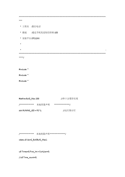
******************************************************************************* **** 工程名:拨打电话* 描述:通过手机发送短信控制LED* 实验平台:STC12XX** : ******************************************************************************* ****/#include ""#include ""#include ""#define Buf2_Max 200 //串口2缓存长度/************* 本地常量声明**************/sbit RUNING_LED = P2^1; //运行指示灯/************* 本地变量声明**************/xdata u8 Uart2_Buf[Buf2_Max];u8 Times=0,First_Int = 0,shijian=0;//u8 Time_count=0;bdata u8 Flag;//定时器标志位sbit Timer0_start =Flag^0; //定时器0延时启动计数器static unsigned char *phone = "ATD10086;\r\n"; //拨打电话,修改这里可以修改拨打的电话。
/************* 本地函数声明**************/void GPIO_config(void);void Timer0Init(void);void CLR_Buf2(void);void Wait_CREG(void);/************* 外部函数和变量声明*****************//****************************************************************************** ** 函数名: main* 描述: 主函数* 输入:* 输出:* 返回:* 注意: 串口2负责与GPRS模块通信,串口1用于下载程序或串口调试,可以避免在下载程序时数据还发送到模块******************************************************************************* /void main(void){GPIO_config();Uart2Init();Timer0Init();EA=1; //开总中断Wait_CREG(); //查询模块是否注册成功UART2_SendString(phone); //拨打电话while(1){;}}/****************************************************************************** ** 函数名: Uart1* 描述: 串口1中断服务入口函数* 输入:* 输出:* 返回:* 注意:*******************************************************************************/void Uart1() interrupt 4{if (RI){RI = 0; //清除RI位}if (TI){TI = 0; //清除TI位}}/****************************************************************************** ** 函数名: Uart2* 描述: 串口2中断服务入口函数* 输入:* 输出:* 返回:* 注意:******************************************************************************* /void Uart2() interrupt 8{IE2 &= ~0x01; //关闭串口2中断if (S2CON & S2RI){S2CON &= ~S2RI; //清除S2RI位Uart2_Buf[First_Int] = S2BUF; //将接收到的字符串存到缓存中First_Int++; //缓存指针向后移动if(First_Int > Buf2_Max) //如果缓存满,将缓存指针指向缓存的首地址{First_Int = 0;}}if (S2CON & S2TI){S2CON &= ~S2TI; //清除S2TI位}IE2 |= 0x01; //使能串口2中断}/****************************************************************************** ** 函数名: Timer0_ISR* 描述: 定时器0中断服务入口函数,20ms中断一次* 输入:* 输出:* 返回:* 注意:*******************************************************************************/void Timer0_ISR() interrupt 1{static u8 Time_count=0;TR0=0;//关定时器Time_count++;if(Time_count>=50){Time_count = 0;RUNING_LED =~RUNING_LED;}TR0=1;//开定时器}/****************************************************************************** ** 函数名: GPIO_config* 描述: IO口配置函数* 输入:* 输出:* 返回:* 注意:******************************************************************************* /void GPIO_config(void){P3M1 &= 0XC3; //配置P32~P35为推挽输出P3M0 |= ~0XC3;RUNING_LED=0;}void Timer0Init(void) //{AUXR &= 0x7F; //12T模式TMOD &= 0xF0; //设置定时器模式16位重载TL0 = 0x00; //设定定时器初值TH0 = 0x70; //设定定时器初值TF0 = 0; //清除TF0标志TR0 = 1; //定时器0开始计时ET0 = 1; //使能定时器0中断}/****************************************************************************** ** 函数名: CLR_Buf2* 描述: 清除串口2缓存数据* 输入:* 输出:* 返回:* 注意:******************************************************************************* /void CLR_Buf2(void){u16 k;for(k=0;k<Buf2_Max;k++) //将缓存内容清零{Uart2_Buf[k] = 0x00;}First_Int = 0; //接收字符串的起始存储位置}/****************************************************************************** ** 函数名: Wait_CREG* 描述: 等待模块注册成功* 输入:* 输出:* 返回:* 注意:******************************************************************************* /void Wait_CREG(void){u8 i;u8 k;i = 0;CLR_Buf2();while(i == 0){CLR_Buf2();UART2_SendString("AT+CREG");UART2_SendLR();delay_ms(5000);for(k=0;k<Buf2_Max;k++){if(Uart2_Buf[k] == ':'){if((Uart2_Buf[k+4] == '1')||(Uart2_Buf[k+4] == '5')) //说模块注册成功{i = 1;break;}}}}}。
- 1、下载文档前请自行甄别文档内容的完整性,平台不提供额外的编辑、内容补充、找答案等附加服务。
- 2、"仅部分预览"的文档,不可在线预览部分如存在完整性等问题,可反馈申请退款(可完整预览的文档不适用该条件!)。
- 3、如文档侵犯您的权益,请联系客服反馈,我们会尽快为您处理(人工客服工作时间:9:00-18:30)。
7、发送 AT+BTPAIR=1,1 //允许手机配对
返回
AT+BTPAIR=1,1
OK
8、之后收到 APP 的配对成功和请求链接服务
+BTPAIR: 1,"MEIZU MX3",22:22:f1:6a:b7:12
+BTCONNECTING: "22:22:f1:6a:b7:12","SPP"
9、确认链接 AT+BTACPT=1 //确认和 APP 建立 SPP 链接
返回
AT+BTACPT=1
OK
10、AT+BTSPPSEND
//发送数据
发送数据有两种方式,定长和非定长
定长方式:
AT+BTSPPSEND=5 //发送 5 个字节数据
收到‘>’这个符号后,输入 5 个字节的数据,超过 5 个字节将丢失后面的数据,只发送前 5 个字节
返回:
AT+BTSPPSEND=5
> 12345
SEND OK
非定长方式:
AT+BTSPPSEND //发送 发数据命令,不带长度
收到‘>’这个符号后,输入想要发送的数据如“1234567890”,
发完数据后,切换到十六进制发送模式,发送十六进制 1A;
AT+BTSPPSEND
> 1234567890�����������������������������������������������������������������������������������������������������������������������������������������������������������������������������������������������������������������������������������������������������������������������������������������������������������������������������������������������������������������������������������������������������������������������������������������������������������������������������������������������������������������������������������������������������������������������������������������������������������������������������������������������������������������������������������������������������������������������������������������������������������������������������������������������������������������������������������������������������������������������������������������������������������������������������������������������������������������������������������������������������������������������������������������������������������������������������������������������������������������������������������������������������������������������������������������������������������������������������������������������������������������������������������������������������������������������������������������������������������������������������������������������������������������������������������������������������������������������������������������������������������������������������������������������������������������������������������������������������������������������������������������������������������������������������������������������������������������������������������������������������������������������������������������������������������������������������������������������������������������������������������������������������������������������������������������������������������������������������������������������������������������������������������������������������������������������������������������������������������������������������������������������������������������������������������������������������������������������������������������������������������������������������������������������������������������������������������������������������������������������������������������������������������������������������������������������������������������������������������������������������������������������������������������������������������������������������������������������������������������������������������������������������������������������������������������������������������������������������������������������������������������������������������������������������������������������������������������������������������������������������������������������������������������������������������������������������������������������������������������������������������������������������������������������������������������������������������������������������������������������������������������������������������������������������������������������������
OK
也可以通过该指令修改蓝牙设备名称
3、手机打开蓝牙助手 APP,点击“连接设备”;
4、点击“扫描新设备”,等待扫描到 SIM800C;
5、点击“SIM800C”,并确认配对;
6、电脑串口会收到 APP 的请求配对信息
+BTPAIRING: "MEIZU MX3",22:22:f1:6a:b7:12,263153
SIM80X 开发板蓝牙 SPP 功能调试笔记
注意:只有 SIM80X 蓝牙版本才具备该功能。
从模式:
1、AT+BTPOWEK”,如果模块蓝牙电源原本已经打开,那么将返回 ERROR。
2、AT+BTHOST? //查询模块名称和地址
返回:
AT+BTHOST?
+BTHOST: Niren,27:a7:2c:90:62:60