Intergraph.CADWorx.V2013.R2(Equipment,P&ID,Plant)中英文版三维工厂设计及建模解决方案
CADWorx2013中文操作手册(从入门到精通 by touefeel)共555页

CADWorxJuly 2012DICAS-PE-200007BCopyrightCopyright © 2003-2012 Intergraph Corporation. All Rights Reserved.Including software, file formats, and audiovisual displays; may be used pursuant to applicable software license agreement; contains confidential and proprietary information of Intergraph and/or third parties which is protected by copyright law, trade secret law, and international treaty, and may not be provided or otherwise made available without proper authorization from Intergraph Corporation.U.S. Government Restricted Rights LegendUse, duplication, or disclosure by the government is subject to restrictions as set forth below. For civilian agencies: This was developed at private expense and is "restricted computer software" submitted with restricted rights in accordance with subparagraphs (a) through (d) of the Commercial Computer Software - Restricted Rights clause at 52.227-19 of the Federal Acquisition Regulations ("FAR") and its successors, and is unpublished and all rights are reserved under the copyright laws of the United States. For units of the Department of Defense ("DoD"): This is "commercial computer software" as defined at DFARS 252.227-7014 and the rights of the Government are as specified at DFARS 227.7202-3.Unpublished - rights reserved under the copyright laws of the United States.Intergraph CorporationP.O. Box 240000Huntsville, AL 35813Terms of UseUse of this software product is subject to the End User License Agreement ("EULA") delivered with this software product unless the licensee has a valid signed license for this software product with Intergraph Corporation. If the licensee has a valid signed license for this software product with Intergraph Corporation, the valid signed license shall take precedence and govern the use of this software product. Subject to the terms contained within the applicable license agreement, Intergraph Corporation gives licensee permission to print a reasonable number of copies of the documentation as defined in the applicable license agreement and delivered with the software product for licensee's internal, non-commercial use. The documentation may not be printed for resale or redistribution.Warranties and LiabilitiesAll warranties given by Intergraph Corporation about equipment or software are set forth in the EULA provided with the software or applicable license for the software product signed by Intergraph Corporation, and nothing stated in, or implied by, this document or its contents shall be considered or deemed a modification or amendment of such warranties. Intergraph believes the information in this publication is accurate as of its publication date.The information and the software discussed in this document are subject to change without notice and are subject to applicable technical product descriptions. Intergraph Corporation is not responsible for any error that may appear in this document.The software discussed in this document is furnished under a license and may be used or copied only in accordance with the terms of this license. No responsibility is assumed by Intergraph for the use or reliability of software on equipment that is not supplied by Intergraph or its affiliated companies. THE USER OF THE SOFTWARE IS EXPECTED TO MAKE THE FINAL EVALUATION AS TO THE USEFULNESS OF THE SOFTWARE IN HIS OWN ENVIRONMENT.Intergraph is not responsible for the accuracy of delivered data including, but not limited to, catalog, reference and symbol data. Users should verify for themselves that the data is accurate and suitable for their project work.商标Intergraph、Intergraph标志、CADWorx和CAESAR II是Intergraph公司及其位于美国国内外的子公司的商标或注册商标。
CADWORX安装及汉化说明
安装选择CADWORX安装盘上的安装文件setup.exe可将CAWORX软件安装到硬盘上,安装过程比较简单。
根据软件提示完成整个安装过程。
注意:当你把安装盘放入光驱,软件会自动运行安装文件,如果没有自动运行,则双击setup.exe 文件。
Plant_PlD 文件夹下的setup.exe 文件包含CADWorx Plant Professional 2013、CADWorx P&ID Professional 2013、CADWorx P&ID 2013 三个文件的安装Steel 文件夹下的setup.exe 文件包含CADWorx Steel Professional Plus 2013的安装CDR 文件夹下的setup.exe 文件包含CADWorx Design Review 2013 和CADWorx Desig n Create 2013 的安装快速启动:1. 运行setup.exe 文件2. 点击安装过程创建的图标,启动CADWORX3. 按照对话框的提示,完成剩下部分的安装4. 第一次运行需要设置一些参数,一般选择默认值就好CADWORX 安装安装类似于大部分软件的安装,以下是安装要求安装驱动器是什么?CADWorx使用哪个版本的AutoCAD?CADWorx安装在什么位置安装CADWorx:1. 把光盘放入光驱2. 点击开始3. 选择运行,或在搜索程序和文件“框中键入以下信息。
4. 在<CD-DRIVE的命令行中键入:\ SETUP .EXE (或单击浏览以找到CD-ROM驱动器上的SETU圧XE。
5. 单击“确定”开始安装。
6. 在“用户帐户控制”,单击“是”以AUTOCAD2010 为例,安装CADWORX7. 在2013安装对话框选择NEXT8. 确认安装在当前用户的电脑上,如果是则选择确的用户登录并重新从 1-7开始安装9. 选择yes 同意许可协议Multipl e User Info rrrat ion4〕 0K ,如果不是则取消安装。
CADWorx2013 简易操作手册

Intergraph CADWorx Plant Suite 三维工厂设计软件基于AutoCAD平台的三维工厂设计软件CADWorx 2013 Plant SuiteIntergraph公司即将推出新一代基于AutoCAD平台的CADWorx Plant Suite三维工厂设计套装软件。
CADWorx Plant Pro采用全新的建模模式,是继Smart Plant 3D,PDS后又一款具有超前革新意识的力作。
Intergraph将继续开发并增强CADWorx软件功能,并努力将其变成设计师手中最好的工具。
最新版本的CADWorx 2013已经发布,几大重要功能更新如下:新的等级、库文件:整合库和等级文件,使界面更加人性化,便于用户管理。
用户可以选择不同的管道等级,设计各种类型的管道,如对焊,丝扣,承插焊,法兰管道,FRP/PVC管道,卫生级食品,医药,消防管道设计和布置。
软件内置了美标、德标、国标、石化、化工的等级和库文件。
智能建模:完全智能化建模,可以随时拖拉出任何需要的元件,并能自动匹配等级与尺寸。
用户可以采用智能拖拽、搭积木法、中心线法等多种方式进行管道建模。
组件功能:常用的阀组、泄放装置、配管布置可以做成组件,多次使用,减少重复的建模过程。
改变尺寸、等级:根据项目需求,如需更改管道的尺寸和等级,只需一个命令即可完成,并保证布置的准确性。
软件集成功能:与管道应力分析软件CAESAR II和压力容器强度设计软件PV Elite双向接口,与SmartPlant 3D、Foundation的集成功能。
亲身体验介绍本次交流会的主要体验内容有创建如下的三维工厂模型:z钢结构模型z设备模型z智能管道建模z支吊架z保温材料z碰撞检查z连续性检查z生成单线图,平面布置图熟悉最新软件CADWorx Plant Professional 2013的新功能(库和等级的创建、智能建模、更改尺寸、更改等级、组件功能等)。
(2024年)CADWorx培训教程

CADWorx培训教程•CADWorx 软件概述•CADWorx 基本操作与界面介绍•绘图工具与编辑技巧•三维建模与渲染技术•管道设计模块详解•设备布置与钢结构设计•电气仪表自动化集成应用目录01 CADWorx软件概述软件背景及发展历程初始阶段CADWorx起源于20世纪90年代,最初是一个为工程设计领域提供2D绘图功能的软件。
发展阶段随着技术的进步和用户需求的变化,CADWorx逐渐增加了3D建模、管道设计、设备布置等高级功能,成为一款综合性的工程设计软件。
成熟阶段近年来,CADWorx不断完善自身功能,同时积极与其他工程设计软件进行集成,提高了工作效率和设计质量。
CADWorx 具备强大的3D 建模能力,可以快速创建复杂的工程模型,提高设计效率。
强大的3D 建模功能CADWorx 提供全面的管道设计工具,支持各种类型的管道、阀门、法兰等元件的建模和编辑,满足管道设计的多样化需求。
丰富的管道设计工具CADWorx 可以自动进行设备布置和优化,减少人工干预,提高设计准确性和效率。
智能化的设备布置CADWorx 支持多种文件格式和数据交换标准,可以与其他工程设计软件进行无缝集成,实现数据共享和协同工作。
良好的兼容性CADWorx 软件特点与优势CADWorx 在石油天然气行业得到广泛应用,用于管道设计、设备布置、工艺流程模拟等方面。
石油天然气行业除了上述行业外,CADWorx 还可以应用于水处理、制药、造纸等多个领域,为工程设计提供全面的解决方案。
其他行业可以提供全面的设计CADWorx 可以提高应用领域与行业现状02 CADWorx基本操作与界面介绍启动与退出CADWorx启动CADWorx通过开始菜单或桌面快捷方式启动CADWorx软件。
退出CADWorx在软件界面中选择“文件”菜单下的“退出”选项,或者使用快捷键Alt+F4退出程序。
界面组成及功能区域划分标题栏显示当前文档的名称和CADWorx软件的版本信息。
Intergraph.CADWorx.2015(Equipment,P&ID.pro,Plant.pro) 智能三维工厂设计及建模解决方案CADWorx
鹰图CADWorx Plant Professional包括进行高效工厂设计所需的最全面的工具。CADWorx Plant简单易学,并已帮助成千上
万的公司更快、更准确的创建创收的交付。
智能3D管道设计
通过等级驱动进行设计
钢结构模块
设备模块
通风管道电缆桥架模块
实时碰撞检查
管段图生成
实时数据库链接
模型—P&ID同步
模型浏览漫游检查模块
包含Intergraph CADWorx P&ID 标准版
与管道压力分析软件和压力容器设计分析软件具有双向接口
ห้องสมุดไป่ตู้
鹰图CADWorx P&ID包括轻松创建智能流程图所需的一切。CADWorx P&ID通过制作图表以及其锁定的信息而释放P&ID的功能,
从而提供给所有利益相关者。
快速直观的创建P&ID
具有大量、用户可修改的图例库
等级驱动的P&ID
与项目数据库的双向链接
元件和项目文件关联
P&ID/与3维模型同步
旧图纸智能转换
P&ID项目图纸发布
自动仪表回路图
生成仪表数据表
生成设备数据表
■ 邮件:hgrjw@ buysoftware@ ■
■ 请 按 Clrt+F 查找, 输入 具体 关键字 查询(不要全部输入) ■
■□■□■□■□■□■□■□■ 长 期 有 效 □■□■□■□■□■□
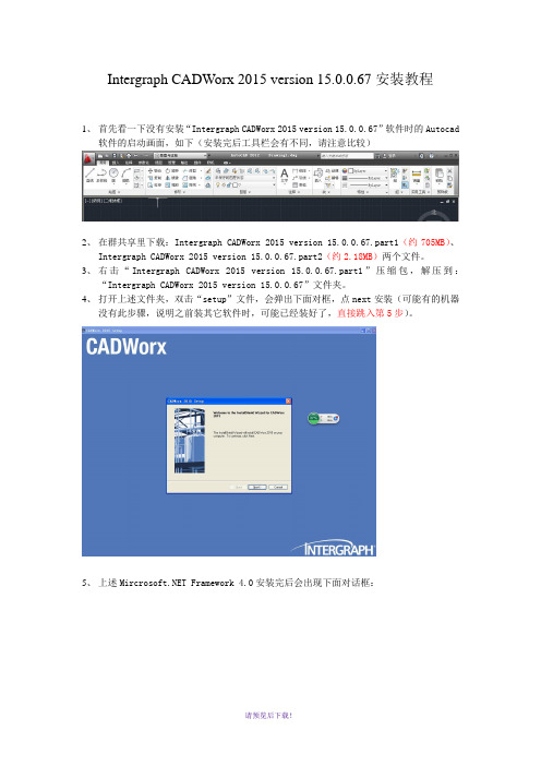
Intergraph CADWorx 2015 version 15.0.0.67安装教程
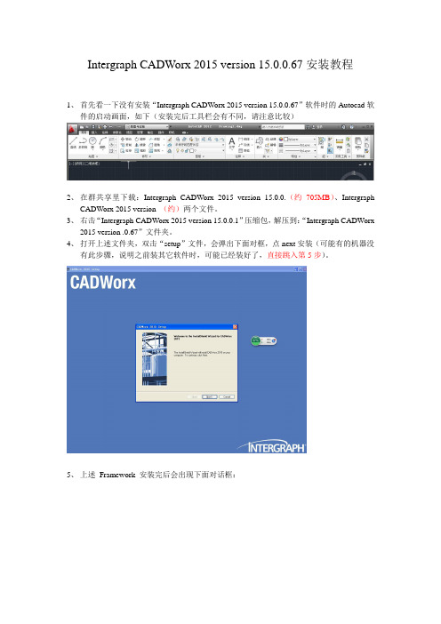
Intergraph CADWorx 2015 version 15.0.0.67安装教程1、首先看一下没有安装“Intergraph CADWorx 2015 version 15.0.0.67”软件时的Autocad软件的启动画面,如下(安装完后工具栏会有不同,请注意比较)2、在群共享里下载:Intergraph CADWorx 2015 version 15.0.0.(约705MB)、IntergraphCADWorx 2015 version (约)两个文件。
3、右击“Intergraph CADWorx 2015 version 15.0.0.1”压缩包,解压到:“Intergraph CADWorx2015 version .0.67”文件夹。
4、打开上述文件夹,双击“setup”文件,会弹出下面对框,点next安装(可能有的机器没有此步骤,说明之前装其它软件时,可能已经装好了,直接跳入第5步)。
5、上述Framework 安装完后会出现下面对话框:点击next出现:确定后,6、点上图“Yes”后,出现下面对话框:7、再点击图标,表示嵌入到AutoCAD软件里了,后出现下面对话框:8、点击“next”后出现下面对话框:9、勾选,后,出现下面对话框:向你要Serial。
10、此时打开上述文件夹“Intergraph CADWorx 2015 version 15.0.0.67”中的Crack文件夹中的“Seriall”记事本文件,输入对应的Serial号。
10、点击next,并修改安装目录路径为D盘11、一直点击Next直到出现下图:12、点击绿色的USB图标后,如下图:13、继续点击Next,直到完成安装。
最后点击确定。
再次点击OK。
14.如果出现以下对话框:表明你缺少文件(win7系统基本不会出现此种情况),到网上下载对应的文件就可以了。
14、最后点击Finish重启电脑:15、重启电脑完电脑,桌面上会多出4个图标。
CADWORX入门级教程(2024)

29
报表数据提取和整理方法
要点一
数据提取
CADWORX提供了丰富的数据提取功能,用户可通过选择 相应的对象(如设备、管道、阀门等)并设置提取参数, 从模型中提取所需的数据。同时,CADWORX还支持从外 部数据源(如Excel、数据库等)导入数据,以满足用户多 样化的数据需求。
要点二
报表输出步骤
首先,在CADWORX中打开相应的工 艺流程图模型;然后,选择需要输出 的报表类型(如设备表),并设置相 应的参数(如输出格式、输出路径等 );最后,点击“生成报表”按钮即 可生成相应的报表文件。
要点三
报表输出效果
生成的报表文件将包含工艺流程图中 所有设备的详细信息,如设备名称、 规格型号、数量、材质等。用户可根 据需要对报表进行进一步的编辑和排 版,以满足特定的输出要求。
多边形绘制
使用“POLYGON”命令来创建多边形。需要指定多边形的边数以及一个点作为多边形的中心点,然后通过 拖动鼠标或输入半径来确定多边形的大小。
13
修改图形对象属性及编辑技巧
属性修改
选择图形对象后,可以通过属性窗口或快捷菜单来修改对象的颜色、线型、线宽等属性。还可以使用 “MATCHPROP”命令或快捷键“MA”来将一个对象的属性匹配到另一个对象上。
并集运算
将两个或多个三维实体合并为一个整体,消除它们之间的重叠部分 。并集运算常用于将不同部分组合成一个完整的模型。
差集运算
从一个三维实体中减去另一个实体,得到剩余的部分。差集运算常 用于创建具有内部空腔或凹陷的模型。
交集运算
取两个或多个三维实体的共同部分,形成一个新的实体。交集运算 常用于创建复杂的几何形状或提取模型中的特定区域。
CADWorx 培训版安装说明

CADWorx培训版安装说明安装条件:1. 安装.NET Framework 4.0(安装目录\\spserver\SPE\CADWorx内部培训\CADworx2014安装文件)2. 安装AutoCAD程序2010及以上版本(破解版CAD2012安装目录\\spserver\SPE\CADWorx内部培训\CADworx2014安装文件\cad2012)。
安装方法:1. 确认已安装了符合要求版本的AutoCAD软件,进入安装目录:\\spserver\SPE\CADWorx内部培训\CADworx2014安装文件\IntergraphCADWorx2014\Intergraph CADWorx 2014\install直接运行cadworx2014.exe,出现如下界面,点击Next。
2. 确认在管理员权限的用户下进行安装,按“确定”按“YES”3.系统会自动识别你安装的CAD版本,如有多个请选择你所在其上加载CADworx 的CAD版本,并按“NEXT”。
4.选择“Install Plant Professional”和“Install P&ID Professional”选项,并输入相应的序列:Plant Pro Serial Number : 00000081401247P&ID Pro Serial Number : 99999913401248或参见“\\spserver\SPE\CADWorx内部培训\CADworx2014安装文件\IntergraphCADWorx2014\Intergraph CADWorx 2014 serial.txt”。
5. 选择程序安装位置,点“NEXT”。
选择授权方式为“SmartPlant License Manager(SPLM)”。
点“是”。
点击“NEXT”等待程序安装完成。
点击”Finish”完成程序安装。
6. 导入破解文件\\spserver\SPE\CADWorx内部培训\CADworx2014安装文件\IntergraphCADWorx2014\Crack将CADWorxEquipment2014H.dll复制到C:\CADWorx 2014\Equipment\Support中,替换同名文件将CADWorxP&ID2014H.dll复制到C:\CADWorx 2014\P&ID\Support中,替换同名文件将CADWorxPlant2014H.dll复制到C:\CADWorx 2014\Plant\Support中,替换同名文件。
CADWorx等级库的制作流程

CADWorx的元件库(Catalog)包含了所有的尺寸、材料、壁厚等级、壁厚、端点类型、元件类别等数据,分为Global、Industry和Company三个层次,分别使用.cat、.ids和.cmp作为后缀名,等级库存放在等级库项目中,后缀名.prj,在之前的版本中,没有这么分,后缀名全部为.gbb,跟PDS的PCD文件有点类似。
这些文件都可以直接用记事本或者notepad等工具打开进行编辑,如果你后面对它们的学习深入以后,其实通过编辑这些文本都可以实现制作元件和等级。
而我们一般情况下都会选择使用软件的SpecEditor工具来进行元件库与等级库的制作。
如下图,软件安装好以后,默认自带的管道数据库以及SpecEditor启动程序存放在C:\CADWorx 2013\Plant\Spec下面。
这个目录下面还存放着一些自定义元件的图形文件和一些配置和预设数据的XML文件。
有意思的事情是,其实安装好以后SpecEditor工具的使用是不需要授权的,这一点和P3D的SpecEditor使用一样。
于是,我们直接可以复制目录下的Spec文件夹到自己的电脑上,即可开始数据库的制作,电脑上可以不用安装CADWorx。
这里给同学们提供单独的最新Spec文件夹下载:SpecEditor下载连接钢结构的数据库后缀名全部为.dat文件,这些文件分别存放在C:\CADWorx 2013\Plant\Steel_I和C:\CADWorx 2013\Plant\Steel_M下,这里面存放了很多种类的型钢,这些dat文件可以通过记事本或者notepad等工具打开进行编辑。
以后的内容我们会逐步介绍如何创建国标的型钢库。
2013.5.20 更新内容CADWorx中建模的时候要先加载一个相应的等级库项目,即.prj文件,这个.prj文件里面存着若干个等级。
首先进入软件后选择左上角的setup进入项目配置。
等级库的调用目录是在Setup下的Configuration Setting中Specification Directory设置,你所要调用的等级库项目必须放在这个目录下,当然,你也可以更改这个目录。
CADWorx2010-7 - Design Review Notes

CADWorx Design ReviewOverviewCADWorx Design Review (CDR) is designed to allow navigation and review of CADWorx models. CDR delivers interactive visualisation and real time walkthroughs of even the largest and most complex 3D CADWorx models to revolutionise design review. Navigating and exploring the design to improve quality and compress the review process is effortless with CADWorx Design Review. The post-production value of the 3D CADWorx model is significantly increased by the wide access to investigate and examine a design that CDR offers.Section 1 – WorkspaceDefault WorkspaceThe CDR interface is intuitive and easy to use. Below is the default CDR workspace.On the right of the screen are the Plan View and Elevation View windows. These display a plan view and an elevation view of the model, and a pointer to indicate the users current position and the direction in which they are facing.Users can drag this pointer around the window to navigate around the model. On the left hand side of the screen are a number of palettes. The available palettes are listed below.Component ListThe Component List palette displays a list of all the CADWorx components in the model.Components in the list can be selected and can have their visibility changed. Using the Check boxes will show/hide the item, or by entering a percentage into the Visibility % column the transparency can be altered.CADWorx PropertiesThe CADWorx Properties palette groups all components into their respective CADWorx categories, whether they are Piping Items, Steel items, Equipment items or HVAC items.Components in the list can be selected and can have their visibility changed. Using the Check boxes will show/hide the item, or by entering a percentage into the Visibility % column the transparency can be altered.XRef ViewThe XRef View palette displays any XRefs which are present in the model and their path relative to the master drawing. Using the Check boxes willshow/hide the XRef, or by entering a percentage into the Visibility % column the transparency can be altered.Layer propertiesThe Layer Properties palette lists all the AutoCAD layers present in the model, including any XREF layers. These layers can be selected from within the list, and all items on the highlighted layer will be selected. Using the Check boxes will show/hide the layers, or by entering a percentage into the Visibility % column the transparency can be altered.Line Number ViewThe Line Number View palette displays all the line numbers in the model, including those present in XREFs. Components in the list can be selected and can have their visibility changed. Using the Check boxes will show/hide the XREF, or by entering a percentage into the Visibility % column the transparency can be altered.PropertiesThe Properties palette can be used to adjust various properties within the CDR environment. The background colour can be changed. The background is a gradient fill so two colours can be selected from the colour chart. Shadows can be added to the model, either soft shadows or hard shadows (or no shadows).Also the drawing properties can be adjusted.The Use Non Selection Gray Scale check box allows the user to choose whether or not when selecting items all non-selected objects are greyed out or kept at their original colour. These non-selected items can also be set to change their transparency using the Non-selection visibility Percent slider. The colour of selected items can be selected using the colour chart.Saved Views and AnimationsThe Saved Views and Animations palette allows users to view and edit their saved views and animation within the model. Views can be restored and can be added into animations. Animations can also be recorded live whilst navigating around the model. This palette will be covered in further detail in Section 3.Section 2 – Opening Files in CDRCDR facilitates the opening of DWG files and DWF files from AutoCAD as well as Hoops Streaming files and Hoops Meta files. CDR automatically creates a HSF file during the initial opening of a file to allow quicker subsequent openings of the file by avoiding the conversion process each time.Open up file Pipework.dwg from the C:\Training\DesignReview\Masters\Piping directory.To open multiple .dwg files, highlight all the required files and open them together...To open additional files into the current scene use the Merge w/ Current Model check box, or alternatively check the Merge Models When Opening option from the menu.(Access the menu by clicking on the in the top left corner)Merge the rest of the files from the directory into the model.Section 3 – Basic NavigationInvestigate navigating around the model. This model provides scope for using the various different types of navigation.Use the Zoom Extents tool to zoom to the extents of the model. This can be a useful tool if you ever get lost in a model for example.Zoom into an area using the Zoom Window tool and Walk around the building. Activating walk mode automatically brings up the Navigation Control PadUsers can use this as an alternative to clicking and dragging on areas in the model to walk. The four main large arrows in the Navigation Control Pad are for walking in the four directions. The user will walk in exactly that direction which the click on.The two arrows at the top allow the user to turn either to the left or to the right. Again the view will turn in exactly that direction and stay on the same point – i.e. no walking forward/backwards.On the right hand side of the Navigation Control Pad is the elevation control. This allows the viewpoint to be moved vertically either up or down.On the left is the Tilt Control. This is similar to tilting your head up or down. Alternatively the user can navigate around the model simply by clicking and dragging in a direction on the model.Scroll the mouse wheel to tilt.Click and hold the mouse wheel and drag either up or down to change elevation.When walking around the model, hold SHIFT to move at 2x speed. Hold CTRL to move at 0.5x speed.Press the space bar to return the tilt back to “flat”.Using the Properties palette change the Non-Select Visibility Percent to 80Using the XREF View palette select the Heat Exchanger drawingThe rest of the model should become semi transparent except for the heat exchanger. Click on the Zoom Selection button to zoom into the heat exchangerIn addition to walk there are the Zoom, Pan, Orbit and Turntable Orbit operators. Users can also display the model in a shaded or wireframe render mode.Investigate and practise with the other Navigation modes.The measure feature can be selected from the Operators panel on the ribbon.Select the Measure tool and measure a known length on the model. To use the measure tool, click on a component, hold the mouse key down and drag to another location and release the mouse key. The start and end coordinates and the overall length will be displayed in the bottom left of the screen.Right-Click MenuPressing the right mouse button at any time displays the following menu.Operators allow the user to select one of the four navigation modes.The 3D Sectioning Tool can be used to temporarily hide part of the model.Practise with this tool to hide the top of the model.The Test Performance option allows users to compare their machines performance with other machines and to display Model Information.The Render Mode options include those on the render modes ribbon and one other.Users can also turn off tooltips.Section 4 – Views and AnimationsViewsAdding a New ViewSaved Views contain the Camera position and focus point, section plane, speeds, rendering conditions and perspective/orthogonal modes.If not already displayed, open the Saved Views and Animations palette by right clicking and choosing Animations and Views from the Windows option.Activate Select modePick the first vertical steel on the pipe work rack and then click the ViewSelected button. Save this view by clicking on the Save Camera Position buttonTo rename a saved view, click on the appropriate view in the <click here to change view name> area.AnimationsCreating a New AnimationUsers have three options when producing an animation, recording theanimation, adding frames manually or a combination of both.Recording an AnimationTo record an animation, choose Begin New Animation from the Animation ribbon.Animation 1 will be added to the Saved Views and Animations Palette.Users can rename the animation by typing the new name in the box to the right of the name.Then click the Record button to begin recording the animation.Orbit, pan and walk through the model, then click Record again to stop the recording.Click Play to play the recording.Creating an Animation by Adding Frames ManuallyTo create an animation by adding frames manually choose Begin NewAnimation from the Animation ribbon.Animation 2 will be added to the Saved Views and Animations Palette.Highlight Animation 2 and click the Add frame to animation 2 button.Move around the model and add another frame. Repeat this until theanimation is finished and click Play. CADWorx Design Review willautomatically interpolate between frames to produce a smooth animation.Editing an AnimationAfter creating an animation, users can edit it by adding or deleting framesmanually or by edited the animation path.Click Show Animation Path on the Animation Ribbon.The animation path will appear with an orientation triad for each of your saved views/frames.Red points toward what you will see, the other arrows point to “up” and “right”. The crosses in the line represent the software generated “steps”. Double-clicking any of the snapshot locators will enable a manipulator control which will allow six axis movement.Click and drag the "*" to move the snapshot in any direction; clicking on an arrow restricts movement to a line defined by the arrow.Mouse-over and click the circular arrow to adjust your yaw, pitch and roll. After editing the animation path, click Play and review the changes. When playing the animation, users can skip to the beginning, go to the next frame or the previous frame and skip to the end.Section 5 – RedliningRedlining allows you to add annotation directly over a viewpoint. It is mutually exclusive to the navigation modes so that when you are redlining, you cannot navigate and vice versa.Redlines can be added to a saved viewpoint.To use the redline tools go to the Edit tab on the CDR Ribbon.The Redline tool allows freehand redlining of the model.The Rectangle draws a rectangle shape from corner to corner.The Circle draws a circle, starting with the centre of the circle.Annotate allows text labels to be added into the model.Annotate Model allows notes with leaders to be attached. Click and hold the mouse button down on the position on the model where you wish the annotation leader to be pointing to and drag to the position on the view where you wish the Note to appear and release. Type in the text required for the note.To erase Annotations use the backspace key.。
PDMS和CADWorx在工程设计中的应用比较

Zonghe Yanjiu♦综合研究]PDMS和CADWo+x在工程设计中的应用比较孙磊王强杨涛(中国船舶集团有限公司第七O三研究所无锡分部,江苏无锡214151)摘要:根据实际发电项目三维设计的应用情况,对PDMS和CADWorx两种设计软件进行了比较分析。
这两种三维设计软件在工程设计中都有着广泛的应用,但是它们又各具特点。
现从多个方面件的使用及特点进行了比较,并根据工程经验,对两种软件的用特点进行了总结。
实际项目中,用户特点、项目规模、员组织结构、项目特殊需求、投资回报等多方面合理选择设计件。
关键词:PDMS;CADWorx;工程设计0引言三维设计现已在工程设计单位、设备制造厂家中广泛普及。
传统的二维设计资工作量较大,图纸二次转效率较低且出错率较,出图及材料统计任务量很大。
三设计可最大限度地减少设计错误,提高整的设计水平和效率。
同时,三设计可直观地示出实模型,可各类信行采和准确汇总,利于实决策的客观性、管理的科学、项目质量的规范性、执行的效以及施工的合理。
AVEVA公司PDMS软件在核电、火电、化工领域应用较为广泛[1,3],在设计院的普及度很,安单其导出的管安装图也非常熟悉。
使用PDMS软件可效地与设计院行和,并效地为施工质量的管安图纸,Intergraph公司基于AutoCAD平台的CADWorx软件,在表4界面元件和数据绑定关系表通道连接表达式连接对象1800启动按钮2801停止按钮3810传送带1运行状态4811传送带2运行状态5812传送带3运行态3.3运行结果200SMART PLC程序编写完成后,下载到PLC。
PLCSIM 仿真的PLC不需要编写PLC程序,只需要硬件组态。
组态后,程序下载到PLCSIM中,启动NetToPLCsim和MCGS编写的HMI程序。
运行的分布式教学平台效果如图3所示。
图3分布式教学平台运行效果各行各业都有广泛应用。
其因平台通用、简单易学,在三维工程设计领域也着要的置⑷。
CADWorx设计方案

CADWorx Plant Professional 软件功能介绍
CADWorx Plant Professional 2010 软件包括:
1、 CADWorx Pipe (管道模块) 用户可以选择不同的管道 等级,设计各种类型的管道, 如对焊,丝扣,承插焊,法兰 管道,FRP/PVC 管道,卫生 级食品, 医药类管道设计和布 置。提供快捷的配管功能,种 类丰富的阀门库和法兰库。 用户可以采用搭积木方法建 立管道模型, 也可以使用中心 线方法建立管道中心线, 然后 自动添加弯头,插入其他元件。用户可以对管道通过管号进行孤立,拷贝,删除,复制,旋 转等操作。
PDS
CADWorx Plant suit
Intergraph 致力于为客户提供全方位三维工厂设计解决方案, 其产品线从 AutoCAD 平台 的 CADWorx,Microstation 平台的 PDS、到独立平台的 SmartPlant 3D 系统,能够满足不同 客户、不同项目之间所有的要求。CADWorx 作为 Intergraph PP&M 家族中新的成员,必将 在 Intergraph 强大的技术基础之上更加快速的发展。
闸阀 Z11H‐16C,25,40,60,100,160;Z41H‐16C,25,40,64,100,160;Z44T‐10,Z941‐16C,25,40,64,100,160; 截止阀 J11H‐25,40,160,320;J13Y‐160I,J13H‐40III;J13W‐40IIICr,160IIICr;J41B‐16,25Z,25Q,25K,25; J41B,25Z,25Q,25K,25;Z41H‐25Q,25K,40Q,16,16C,25,40,64,100,160;J41Y‐25I,40I,100I,25P,40P,160P,16R;J41F‐16;J 41Fs‐16; 止回阀 H41H‐16,25,40,64,100,160;H44T‐10;H44W‐10;H44X‐10;H44H‐40,64,100,160; 安全阀 A21F‐16,16C,25,40,64,16P,40P;A41H‐16C,25,40,16P,25P,40P; 球阀 Q11F‐25,40,64,16R,25R,40R,64R;Q41F‐64,160,320,6P,16P,25P,40P,64P; 蝶阀 D71X‐10,16;DTD71F‐10P;DTD71F1‐16C,25,40;DTD71(H)‐16C,25,40;D71H‐16C,25,40;D73H‐16C, 25,40;D73H‐16C,25,40;D73Y‐16P;DTD71F‐16P,25P,40P;D373‐16P;DTD371F1‐16C,25,40; DTD371(H)‐16C,25,40;D371H‐16C,25;DTD371F‐16P,25P;D373H‐ 16C,25;D373Y‐16P,25P,40P; 该管道元件数据库可以由客户任意扩充和添加,根据不同需求随时更改!
CADworx中文版帮助(未完)
约定在回顾本指南,重要的是要理解这些术语和文档中使用的约定。
使用下面的信息来确定公约和类型的信息。
约定资料类别<INSTALL-DIR> 这指的是您的计算机上CADWorx安装目录。
例如,C:\CADWorxPlant。
代替你的安装目录的任何地方使用这个符号。
<ACAD-DIR> 这是指你AutoCAD的安装目录。
例如,C:\ AutoCAD 2000i。
代替你的安装目录的任何地方使用这个符号。
<CD-DRIVE> 这是指您的CD - ROM驱动器。
替代您的CD - ROM驱动器在任何地方使用这个符号。
Command Line 项目必须输入或出现在AutoCAD的命令行。
User Responses这是指用户的反应,命令提示。
Commands CADWorx和AutoCAD命令。
选项命令行选项CAPITALS AutoCAD的系统变量或关键字。
KEY+KEY 组合键的用户必须按住一个键,然后按一个,例如,按CTRL + P 或Alt + F4关闭。
计划支持/用户帮助CADWorxPlant开发了设计师和工程师,设计师和工程师。
CADWorxPlant的设计针对性的易用性,广泛应用,转让链接到管道压力,克服了其他管道CAD软件包的限制。
CADWorxPlant可以提供字形,等长,和三维模型。
与其他软件,比如的NavisWorks,实时演练和近阴影照片质量可以生成演示。
在许多情况下,困难和目前的软件产品的不完备使得绘制三维一偶然事件。
CADWorxPlant解决这些问题-模型可以产生单线成字形平面图和立面图,或转换成三维打开。
另外,该模型可以构造最初使用的3D对象。
在AutoISO选项使Word 自动建立,放手经营管网图。
CADWorxPlant一个主要功能是它的双向数据与管道应力程序凯撒二链接。
使用此链接,一个模型可以生成民航方面,转入分析和修改到凯撒二,然后改变模式转移绘制修改回来。
CAESAR II 中的弹簧选型

8
© Intergraph 2013
以前的选择 – 5: 模型中可能的选择
程序可能选择刚性约束、弹簧支吊架或者恒 力弹簧支吊架。
所有管道系统都涵盖这三种支吊架:
刚性约束 代表一个刚性的垂直约束 弹簧 表征一个柔性的垂直约束(K=弹簧选型刚度)
和一个预加荷载的组合(计算出的安装荷载) 恒力支吊架 代表一个向上的支撑力,并会在约束
在不含重量情况下计算垂直位移
4
© Intergraph 2013
选型过程– 1: 怎样得到数据
计算指定位置的平衡荷载
对指定的每个弹簧设计的位置进行重量分析,用+Y刚 性支架替代弹簧分配重量[假设+Y朝上]
+Y 支架的荷载即为平衡荷载
计算每个指定位置的垂直位移
用“平衡载荷”替换+Y支撑进行操作工况的计算 得到位移,去掉上一步添加的力。
输入界面 – 特别设置 Hanger Design Control Data (1/2)
这里,设置如下的弹簧控 制参数:
弹簧工况数量= 2 多工况设计选项=
Operating Case 1 在模型输入界面, 重设右侧
的弹簧为: 多工况设计选项= Operating Case 2
24
69) 减小敏感设备附近的载荷变化 (例如:恒力弹簧载荷变
化大约为6%)
27
© Intergraph 2013
输入界面 – 通用 Hanger Design Control Data (2/2)
刚性支架位移标准
如果弹簧位置的垂直位移小于这个值,CAESAR II将 选择一个刚吊 (如 Y 向约束)
对当前的模型设置通用设置及初始设置值
Intergraph-CADWorx-2015-version-15.0.0.67安装教程
Intergraph CADWorx 2015 version 15.0.0.67安装教程1、首先看一下没有安装“Intergraph CADWorx 2015 version 15.0.0.67”软件时的Autocad软件的启动画面,如下(安装完后工具栏会有不同,请注意比较)2、在群共享里下载:Intergraph CADWorx 2015 version 15.0.0.67.part1(约705MB)、Intergraph CADWorx 2015 version 15.0.0.67.part2(约2.18MB)两个文件。
3、右击“Intergraph CADWorx 2015 version 15.0.0.67.part1”压缩包,解压到:“Intergraph CADWorx 2015 version 15.0.0.67”文件夹。
4、打开上述文件夹,双击“setup”文件,会弹出下面对框,点next安装(可能有的机器没有此步骤,说明之前装其它软件时,可能已经装好了,直接跳入第5步)。
5、上述 Framework 4.0安装完后会出现下面对话框:点击next出现:确定后,6、点上图“Yes”后,出现下面对话框:7、再点击图标,表示嵌入到AutoCAD软件里了,后出现下面对话框:8、点击“next”后出现下面对话框:9、勾选,后,出现下面对话框:向你要Serial。
10、此时打开上述文件夹“Intergraph CADWorx 2015 version 15.0.0.67”中的Crack文件夹中的“Seriall”记事本文件,输入对应的Serial号。
10、点击next,并修改安装目录路径为D盘11、一直点击Next直到出现下图:12、点击绿色的USB图标后,如下图:13、继续点击Next,直到完成安装。
最后点击确定。
再次点击OK。
14.如果出现以下对话框:表明你缺少文件(win7系统基本不会出现此种情况),到网上下载对应的文件就可以了。
CADWorx高效应用小技巧
2016 CADWorx高效应用小技巧CADWorx Steel 钢结构库文件.o删除不需要的钢结构文件. o更快更方便的选择结构•CADWorx Plant Pro 非垂直的偏置连接精确建模o偏置连接(开口焊)时OTAP 是单独使用的.o当前偏置连接不会考虑管道的角度,只会以90垂直的方式连接主管. o这将导致单线图出图不准.o使用AutoCAD ALIGN 命令修改OTAP 放置. o抱枕单线图出图准确•CADWorx Plant 密度计–用户自定义元件o密度计用来测量流动液体的密度,可以检测不同的密度和粘度的液体.o使用用户自定义元件时非常困难的,因为该元件没有端面类型且是夹着管子的o自定义元件在插入的时候会将管线打断o可以将该元件按支吊架处理o得到预期的结构且不需要切断管线.•CADWorx Plant 弯管o弯管可以使用BENT 命令建模.o CADWorx2015 支持弯管的单线图出图. o甚至可以修改弯管的SKEY为PBBWo Curve Threshold(弯曲值)在单线图中可以被定制. o将值改为1.0, 默认的是0•在等级中放置weld并设置类型•IsogenOut vs IsogenBatch •ISOGENContinuationGraphicsCount –单线图显示图形:–0 –不显示连接图形.– 1 –显示一个元件.– 2 –显示两个元件– 3 –显示三个元件•Symbol Information –Symbol信息.•Message –单线图中元件显示信息.•Spindle / Flat / Support Direction-指定阀杆方向•Flow Arrow –阀门流向.•Miter Pipe Export Options-虾米管输出设置.•Other•Spool –指定管段号,将替换软件自动生成的管段号.•Sketch -指定dwg详图.•Dim Status-指定图纸中绘图样式,虚线、实线等.•Sheet # -指定图纸编号.•Mark –为元件指定编号.•End Connections and Conditions –端部连接坐标s•Reference Dimensions –参照信息t.•为管线增加设备参照信息•Isogen 批量输出o确保正确配置页面设置.o项目初期即设定好.o这样可以确保所有后续的单线图具有相同的参数使批量印刷容易得多o使用发布命令绘制多个文件.o如果没有找到有效页面设置然后将显示错误,图纸不会绘制o附加选项可用于批处理转换为PDF.•CADWorx P&ID P&ID中显示信息o在P&ID中运行DATAEXTRACTION 命令o基于当前绘画创建一个新的数据提取. o选择选项从块中提取对象.o不从外部参照提取对象.o根据列表的类型选择相关的块的属性o对Process Linelist是TAG_NUMBER 块, 对于Equipment list是VESSEL_LAB block.而Valvelist是VAL** 命名的块o块的名称与P&ID Symbols.dat 文件相关.o使用过滤功能来协助选择.o每列都可以重新命名. o可以重新设定排序.o数据与P&ID关联.o This workflow will work for both P&ID Professional and P&ID Basic versions of CADWorx P&ID.2016 Thank you message Sign off message。
三、Cadworx设备建模
Thickness壁厚 Diameter 直径 Cylinder 圆柱体 筒体
(2)封头(椭圆形封头)head 封头 factor因子
椭圆形封头,head factor是 封头顶部系数 Flip orientation 是否要翻转方向(上下颠倒)
2 布置角度 为绕筒体中心轴旋转角度。 3 D 为法兰面到中心轴的距离
1 各个参数的 意思。
2 封头上各个 参数和筒体 上各个参数 不同含义。 3 补强圈
4 管嘴延伸段
1 封头上 距离 指的是 x方 向偏移,偏 移距离指的 是y方向偏 移。
(8) 塔设备附属的平台与梯子
(8) 鞍座(支管台)
鞍座
如A包含B,并且B以覆盖形式参照到A中。 若将A以覆盖方式参照到C中,那么C中看不 到B的存在。
附着(二次附着显示)
以附着的方式插入外部参照,若插入的外部 参照图形自身包含被附着的外部参照,当前 图形文件可以显示被附着的外部参照。
如A包含B,并且B以附着形式参照到A中。 若将A以附着方式参照到C中,那么C中可以 显示B。
搜索路径中。 找到 cadworx2015/plant/support/acad.rx 写字板打开上述文件,加入一行
cadworxEquipment2015.arx 然后保存 命令行 键入 em 或者 工厂-设备面板
1 软件设置
1 软件设置
菜单栏
设备控制面板
元件区:第一行静设备,第二行动设备和设置、帮助
长度 (Length)是封头直边的长度(图中h1)
(2)封头(碟形封头)
图中,长度ha(length)也是直边段长度,转向节半径r (过渡圆弧半径)是144.75
CadWorx快速教程
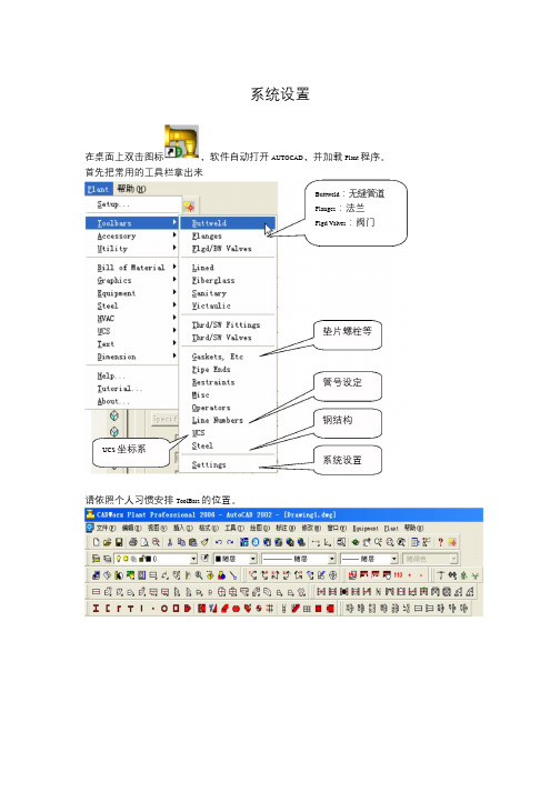
系统设置在桌面上双击图标,软件自动打开AUTOCAD,并加载Plant 程序。
首先把常用的工具栏拿出来Buttweld:无缝管道Flanges:法兰Flgd Valves:阀门垫片螺栓等管号设定钢结构UCS 坐标系系统设置请依照个人习惯安排ToolBars 的位置。
Steel钢结构1,生成柱网可以取出保存的结构尺寸属性。
如果设置了偏移量则图形可绘制梯形可以保存设置好的结构尺寸属性。
2,加入钢结构点击选择工字钢型号后用“”按钮来框选柱网,钢结构即可加上。
3,梯子和护栏用Pline 画三个辅助面。
俯视图楼梯:点击,Stair 楼梯有三个tab 属性页从屏幕选择梯从屏幕上获得从屏幕上获得子的方向由点1 到点2插入点○1 标高点○2楼梯的宽度楼梯的高度楼梯的长度图中○4 的位置,第二点在○3 的位置,方向由○4 指向○3 。
注意:楼梯要从高到低绘制。
直梯:点击图标从屏幕上选点从屏幕上选直梯方向,或直接输入角度。
点击“OK”后,先选点1,再选点2 楼梯自动生成。
注意:直梯要从低向高绘制。
护栏:首先关闭Steel 图层,然后点击图标,出现护栏属性框,沿着中心线直接绘制Equipment设备1.设备属性New 一张新图,激活设备模块,命令行输入“em”泵的各项元件容器的各项元件Placement 设备定位Components 元件属性对设备“新建”、“改名”和“删除”指定定位点的值或从屏幕获得指定旋转角度或从屏幕获得设备主体的方向是垂直的还是水平的管嘴表现型式可以为中空2.卧式容器<1>点击“New”新建卧式容器名称定为“D-001”名称确定后点击“ok”,在屏幕的(0,0,0)点上插入了设备定位点一个“小十字”。
注意:新建设备的定位点永远默认是(0,0,0)点。
<2>依次点击封头、筒体、封头切换到空式模式即可看到设备的大体样子了。
<3> 点击元件属性,可以看到D—001 已经有了三个元件的属性分别是封头、筒体和封头。
试论CADWorx在管道设计中的应用_曾德芝

2013年山东工业技术Shandong Industrial Technology第10期1三维建模流程在三维建模前,需要做一系列准备工作,包括工艺流程图,设备布置图,工艺管道表,土建的场地平整图,设备厂家的制造图等,在这些输入文件的基础上,建立反映全厂概貌的模型,包括厂区主要道路,厂房,机械设备,在全厂概貌模型的基础上,进行管道布置研究。
确定厂区主管廊的走向及标高,藉此检验流程与设备是否顺畅。
然后编制项目中需要使用的各个等级的管材数据库,CADWorx 自带65个管道等级,但也可根据业主要求的管道等级标准自建管材数据库。
2管道等级和元件库管道等级和元件库是建立三维模型的基础。
CADWorx 支持用户自定义元件库和建立等级库。
管道等级可以按照具体的要求分类(如按照压力)把各个元件库文件有机的组合到一起,使得用户绘图时不用关心多而杂的元件文件。
所有的管道等级文件都以扩展名为SPC 存放在\Spec 目录下,在该目录下SpecEdit.exe 文件可以完成管道等级的建立和修改。
元件库是指以文件的形式记录各个元件(管道、阀门、法兰等)的具体参数(公称直径、厚度、长度等)。
CADWorx 在安装时会生成很多的元件库文件,分别放在三个目录下,每个目录文件大致相同,区别就是其中元件参数的量度单位不同:\LIB_I (公称直径和长度都是英制)、\LIB_M (公称直径是英制,长度是公制)、\LIB_MM (公称直径和长度都是公制)。
3自定义的初始化文件这个设置是控制三维工厂设计软件的全部环境参数控制,它涵盖:配管环境:管道直径、管道等级、管道显示模式图框和比例图层的控制项目环境变量定义4钢结构和和设备模块通过Steel 模块,可以方便地建立结构模型,建立用户的管架和框架,设置好结构尺寸属性,生成柱网,点击选择工字钢型号,完成钢结构,同时,Steel 模块还可生成基础平台,梯子和护栏。
通过设备模块可以通过搭积木的方式生成各种设备和容器,包括卧式/立式容器,塔、泵,设定设备尺寸、管嘴形式等等。
- 1、下载文档前请自行甄别文档内容的完整性,平台不提供额外的编辑、内容补充、找答案等附加服务。
- 2、"仅部分预览"的文档,不可在线预览部分如存在完整性等问题,可反馈申请退款(可完整预览的文档不适用该条件!)。
- 3、如文档侵犯您的权益,请联系客服反馈,我们会尽快为您处理(人工客服工作时间:9:00-18:30)。
26、Intergraph.SmartPlant.3D.V6.1(2006)
Intergraph.SmartPlant.3D.V6.1(2006) Intergraph的企业级工程软件提供三维设计、完整性评估和安装规划功能 Intergraph? SmartPlant?企业级工程解决方案在全球规模一流的数十亿美元燃煤发电厂的设计和成功运营中发挥了关键作用。 Sma...
10、Intergraph.CADWorx.V2013.R2(Equipment,P&ID,Plant) 中英文版
Intergraph?CADWorx? 2013 Plant Professional 鹰图公司于2012年4月推出新一代基于AutoCAD?平台的、智能的三维工厂设计及建模解决方案CADWorx? Plant Professional 2013。最新版本的CADWorx 2013不仅易学易用,而且具有...
Creating Piping Models with PDS 3D(Intergraph原厂培训教ign System(PDS)v7.2 Documentation-ISO 1CD
Intergraph Plant Design System(PDS)v7.2 Documentation-ISO 1CD
8、Intergraph Erdas Imagine-LPS-ER Mapper 2013 1DVD
Intergraph Erdas Imagine-LPS-ER Mapper 2013 1DVD ERDAS IMAGINE 2013 expands on this proven technology with a host of usability enhancements and new featuresthat enable you to do more with more types of data. During thi...
+
+ 联.系Email: hgrjw@ buysoftware@
+++++++++++++++++++++++++++++++++++++++++++++++++++++++++++++++++
19、Creating Piping Models with PDS 3D(Intergraph原厂培训教程)
2、Intergraph SmartPlant 3D 2011 R1 v09.01.30.0055 1DVD最新版
Intergraph SmartPlant 3D 2011 R1 v09.01.30.0055 1DVD最新版 ntergraph的企业级工程软件提供三维设计、完整性评估和安装规划功能 Intergraph? SmartPlant?企业级工程解决方案在全球规模一流的数十亿美元燃煤发电厂的设计和成功运营中...
21、Intergraph SmartPlant Enterprise 2007-ISO 2DVD
Intergraph SmartPlant Enterprise 2007-ISO 2DVD
22、Intergraph Plant Design System(PDS)v08.00-ISO 2CD(也就是Intergraph PDS,工厂设计软件)
+
+ 长期有效,需要联系:
+
+ 联 系 Q. Q:1140988741 电 话(TEL):18980583122
+
+ Skype: buysoftware@
6、Intergraph SmartPlant PID 2009 SP5 1CD
Intergraph SmartPlant PID 2009 SP5 1CD Intergraph SmartPlant企业解决方案是一个集成的解决方案套件,它能够在其整个生命周期里为EPC和业主运营商设计、施工、安全地运营和维护一个工厂。结合在一起的IPS和Intergraph解决方案将使所...
Intergraph SmartPlant 3D 2011 R1 v09.01.30.0055 1DVD最新版
Intergraph SmartPlant Review 6.2.0.34 1CD(三维工厂模型浏览和设计检查)
Intergraph SSK v6.1-ISO 2DVD基于数字影象的数字立测图系统
3、Intergraph SmartPlant Review 6.2.0.34 1CD(三维工厂模型浏览和设计检查)
Intergraph SmartPlant Review 6.2.0.34 1CD(三维工厂模型浏览和设计检查) smartPlant Review是美国Intergraph公司专门为PDS和SlllartPlant 3D设计的工厂模型漫游检视软件。SnlartPlant Review是一个用于交互式浏览大型复杂三维模型的...
24、Intergraph SmartPlant 3D v6.1-ISO 1CD(工厂设计软件)
Intergraph SmartPlant 3D v6.1-ISO 1CD(工厂设计软件)
25、Intergraph.SmartPlant.3D.V6.1(2006)
Intergraph.SmartPlant.3D.V6.1(2006) Intergraph的企业级工程软件提供三维设计、完整性评估和安装规划功能 Intergraph® SmartPlant®企业级工程解决方案在全球规模一流的数十亿美元燃煤发电厂的设计和成功运营中发挥了...
11、Intergraph SmartPlant Enterprise 2007 2DVD
Intergraph SmartPlant Enterprise 2007 2DVD
12、Intergraph SmartPlant 3D 2009-ISO 1DVD
Intergraph SmartPlant 3D 2009-ISO 1DVD
9、Intergraph SmartSketch 2009.1.v6.01.00.31-ISO 1CD(参数化高级二维智能绘图软件包)
Intergraph SmartSketch 2009.1.v6.01.00.31-ISO 1CD Intergraph SmartSketch v5.00.21 1CD(参数化高级二维智能绘图软件包) SmartSketch是一个创新的产品为技术办公室,结合世界一流的商业图表与获奖绘图技术。它是一个通用的、具有成本...
Intergraph GeoMedia v6.1 Pro-ISO 1CD
18、Intergraph SmartPlant Review 中文使用手册
Intergraph SmartPlant Review 中文使用手册
+++++++++++++++++++++++++++++++++++++++++++++++++++++++++++++++++
Intergraph PDS v2011 1DVD
1、Intergraph smartplant Intools v8.0-ISO 1CD仪表设计软件
Intergraph smartplant Intools v8.0-ISO 1CD仪表设计软件 SmartPlant 3D、PDS、intools、SmartPlant P&ID都是美国Intergraph(鹰图)公司著名的设计软件。 INtools在设计和交付的全过程中保持了连贯性。包括通过用标准报告工具和用平...
4、基于数字影象的数字立测图系统 Intergraph SSK v6.1-ISO 2DVD
ImageStation SSK 是基于数字影象的数字立测图系统。它把解析测图仪、正射投影仪、遥感图象处理系统集成为一体,与 GIS (地理信息系统)以及 DTM (数字地形模型)在工程 CAD 中的应用紧密结合在一起,形成强大的具备航测内业所有工序处理能...
Intergraph Plant Design System(PDS)v08.00-ISO 2CD(也就是Intergraph PDS,工厂设计软件)
23、Intergraph Intools Engineering Suite v5.2-ISO 1CD(国际顶级仪表工程的设计软件)
Intergraph Intools Engineering Suite v5.2-ISO 1CD(国际顶级仪表工程的设计软件)
Intergraph.CADWorx.V2013.R2(Equipment,P&ID,Plant)中英文版三维工厂设计及建模解决方案
鹰图公司最新版本的CADWorx 2013不仅易学易用,而且具有几大重要特点如下: