Stamford-AVR
发电机原理及特性

康明斯/斯坦福凸极同步发电机
发电机基本结构和电路
AVR输 出直流 电给励 磁定子 P2 -P3 -P4 A.V.R 6-7-8 励磁转子 和定子 XX- (F2) 主定子
从主定子来 的交流电源 和传感信号 (2相或3相 感应)
X+ (F1)
主转子
轴承 轴
PMG提供电 源给AVR( 安装时)
整流模块
气隙分布接近正弦波形状
自 励 (系列4)
电力输出 电力
检测
输出
A.V.R.
励磁机磁场 (定子)
主机定子
主机磁场 ( 转子 )
旋转二极管 机械旋转 动力输入
励磁机 转子 (电枢)
永 磁 机 励 磁 (系列3)
电力输出
参考值设定
检测
输出
A.V.R.
主机定子
励磁机磁场 (定子)
永磁机 定子
主机磁场 (转子)
主定子和转子
永磁发电机转子和永磁体定子
电磁场概念
• 电荷:物质的固有属性之一。 • 电量守恒定律:电荷在转移前后,其总电量不变。 • 电场:电荷周围空间存在的一种特殊物质。 • 磁场:电流周围空间存在的一种特殊物质。
• 电场与磁场共同存在。
• 变化的电场可以产生磁场;变化的磁场可以产生电场。 • 电磁感应定律:当穿过任何闭合回路所界定面积中的磁 通量发生变化时,在回路中产生的感应电动势等于该磁 通量对时间的变化率的负值:
STAMFORD发电机型号
产 品 型 号 说 明
I
型号
控制系统 MX341/ MX321 SX440/ SX421
陆用 船用 机座号
极数
轴承数
铁芯长度
同步发电机的基本结构
沃尔沃柴油发电机组
400K W沃尔沃柴油发电机组技术协议甲方:南阳二机石油装备(集团)有限公司乙方:南阳新成高架设备有限公司南阳二机石油装备(集团)有限公司(甲方)与南阳新成高架设备有限公司(乙方)关于大庆石油管理局钻探集团钻井一公司ZJ40DJ钻机上面的1000kW济柴发电机组和2×400kW沃尔沃柴油发电机组并机(带机房及并机柜),经过双方协商,达成如下技术协议:一、供电系统总体技术要求1、系统的设计制造依据“安全、可靠、先进、方便、实用”的原则,其动力控制系统,交流输出特性,控制操作和各种保护功能等应能满足用户的要求。
采用正确可靠的防潮、防水、防火措施,符合安全操作要求,接口满足系统要求;使用环境温度-40℃~+50℃。
2、模块化设计,满足快速、安全地搬迁、安装、拆卸要求,整机尺寸满足铁路运输和汽车运输的要求。
具有使用、维护、检修方便等特点。
3、外观精美,实用性强,满足高寒、多雨、多风沙环境下作业要求。
4、系统设计、制造标准应符合下列标准:GB2820-90工频柴油发电机组通用技术条件符合钻井行业HSE要求:符合其它有关电气标准;ISO3046 ISO8528 GB3096 IEC34 ISO9001 ISO14000等。
安全防护性能符合NAME1标准。
二、柴油发电机组的构成1、主发电机组为1000kW济柴发发电机组、1栋机房、相关动力电缆及附件等全套动力系统。
正常工作由主发电机组供电。
2、辅助发电机组为2×400kW两台(400kW/500kVA、400V、50Hz)瑞典沃尔沃(VOLVO)柴油发动机、英国斯坦福交流发电机(STAMFORD)及美国GAC电子调速系统和北京兰泊得机组并车控制系统配套而成的柴油发电机组, 1栋机房、相关动力电缆(房内连接电缆)及附件等全套动力系统。
当主发电机组出现故障时由两台辅助发电机组供电。
主发电机控制在MCC房内控制,辅助发电机组在两房中间并机房内控制,主发电机不带油箱,辅助发电机带油箱,机房预留加油、回油口。
新亚汤诺机械工业电源生成器UCI224D技术数据表

UCI224D - Technical Data SheetUCI224DSPECIFICATIONS & OPTIONSSTANDARDSNewage Stamford industrial generators meet the requirements of BS EN60034and the relevant section of other international standards such as BS5000,VDE 0530, NEMA MG1-32, IEC34, CSA C22.2-100, AS1359. Other standards and certifications can be considered on request.VOLTAGE REGULATORSSX460 AVR - STANDARDWith this self excited control system the main stator supplies power via the Automatic Voltage Regulator (AVR)to the exciter stator.The high efficiency semiconductors of the AVR ensure positive build-up from initial low levels of residual voltage.The exciter rotor output is fed to the main rotor through a three phase full wave bridge rectifier.This rectifier is protected by a surge suppressor against surges caused, for example, by short circuit.SX440 AVRWith this self-excited system the main stator provides power via the AVR to the exciter stator.The high efficiency semi-conductors of the AVR ensure positive build-up from initial low levels of residual voltage.The exciter rotor output is fed to the main rotor through a three-phase full-wave bridge rectifier.The rectifier is protected by a surge suppressor against surges caused,for example,by short circuit or out-of-phase paralleling.The SX440will support a range of electronic accessories,including a'droop'Current Transformer (CT)to permit parallel operation with other ac generators.If3-phase sensing is required with the self-excited system, the SX421 AVR must be used.SX421AVRThis AVR also operates in a self-excited system.It combines all the features of the SX440with, additionally,three-phase rms sensing for improved regulation and performance.Over voltage protection is provided via a separate circuit breaker.An engine relief load acceptance feature is built in as standard.MX341 AVRThis sophisticated AVR is incorporated into the Stamford Permanent Magnet Generator(PMG)control system.The PMG provides power via the AVR to the main exciter,giving a source of constant excitation power independent of generator output.The main exciter output is then fed to the main rotor,through a full wave bridge,protected by a surge suppressor.The AVR has in-built protection against sustained over-excitation, caused by internal or external faults.This de-excites the machine after a minimum of 5 seconds.An engine relief load acceptance feature can enable full load to be applied to the generator in a single step.If three-phase sensing is required with the PMG system the MX321 AVR must be used.We recommend three-phase sensing for applications with greatly unbalanced or highly non-linear loads.MX321 AVRThe most sophisticated of all our AVRs combines all the features of the MX341with,additionally,three-phase rms sensing, for improved regulation and performance. Over voltage protection is built-in and short circuit current level adjustments is an optional facility. WINDINGS & ELECTRICAL PERFORMANCEAll generator stators are wound to2/3pitch.This eliminates triplen(3rd,9th,15th…)harmonics on the voltage waveform and is found to be the optimum design for trouble-free supply of non-linear loads.The 2/3pitch design avoids excessive neutral currents sometimes seen with higher winding pitches,when in parallel with the mains.A fully connected damper winding reduces oscillations during paralleling.This winding,with the2/3pitch and carefully selected pole and tooth designs,ensures very low waveform distortion.TERMINALS & TERMINAL BOXStandard generators are3-phase reconnectable with12 ends brought out to the terminals,which are mounted on a cover at the non-drive end of the generator.A sheet steel terminal box contains the AVR and provides ample space for the customers'wiring and gland arrangements.It has removable panels for easy access.SHAFT & KEYSAll generator rotors are dynamically balanced to better than BS6861:Part1Grade2.5for minimum vibration in operation.Two bearing generators are balanced with a half key.INSULATION/IMPREGNATIONThe insulation system is class 'H'.All wound components are impregnated with materials and processes designed specifically to provide the high build required for static windings and the high mechanical strength required for rotating components. QUALITY ASSURANCEGenerators are manufactured using production procedures having a quality assurance level to BS EN ISO 9001.The stated voltage regulation may not be maintained in the presence of certain radio transmitted signals.Any change in performance will fall within the limits of Criteria'B'of EN61000-6-2:2001.At no time will the steady-state voltage regulation exceed 2%.NB Continuous development of our products entitles us to change specification details without notice,therefore they must not be regarded as binding.Front cover drawing typical of product range.2CONTROL SYSTEM SEPARATELY EXCITED BY P.M.G. A.V.R.MX321MX341VOLTAGE REGULATION ± 0.5 %± 1.0 %With 4% ENGINE GOVERNINGSUSTAINED SHORT CIRCUIT CONTROL SYSTEM SELF EXCITED A.V.R.SX460SX440SX421VOLTAGE REGULATION ± 1.5 %± 1.0 %± 0.5 %With 4% ENGINE GOVERNINGSUSTAINED SHORT CIRCUIT SERIES 4 CONTROL DOES NOT SUSTAIN A SHORT CIRCUIT CURRENTINSULATION SYSTEM CLASS H PROTECTIONRATED POWER FACTOR STATOR WINDING WINDING PITCH WINDING LEADSSTATOR WDG. RESISTANCE ROTOR WDG. RESISTANCE EXCITER STATOR RESISTANCE EXCITER ROTOR RESISTANCE R.F.I. SUPPRESSION BS EN 61000-6-2 & BS EN 61000-6-4,VDE 0875G, VDE 0875N. refer to factory for othersWAVEFORM DISTORTION NO LOAD < 1.5% NON-DISTORTING BALANCED LINEAR LOAD < 5.0%MAXIMUM OVERSPEED BEARING DRIVE END BEARING NON-DRIVE ENDWEIGHT COMP. GENERATOR WEIGHT WOUND STATOR WEIGHT WOUND ROTOR WR² INERTIASHIPPING WEIGHTS in a crate PACKING CRATE SIZE TELEPHONE INTERFERENCE COOLING AIRVOLTAGE SERIES STAR380/220400/231415/240440/254416/240440/254460/266480/277VOLTAGE PARALLEL STAR190/110200/115208/120220/127208/120220/127230/133240/138VOLTAGE SERIES DELTA220/110230/115240/120254/127240/120254/127266/133277/138kVA BASE RATING FOR REACTANCE VALUES505050486062.562.565Xd DIR. AXIS SYNCHRONOUS 2.33 2.10 1.95 1.67 3.04 2.83 2.59 2.47X'd DIR. AXIS TRANSIENT 0.180.160.150.130.220.200.190.18X''d DIR. AXIS SUBTRANSIENT 0.120.110.100.090.150.140.130.12Xq QUAD. AXIS REACTANCE 1.070.970.900.77 1.40 1.30 1.19 1.14X''q QUAD. AXIS SUBTRANSIENT 0.140.130.120.100.140.130.120.11X L LEAKAGE REACTANCE 0.070.060.060.050.090.080.080.07X 2 NEGATIVE SEQUENCE 0.130.120.110.090.140.130.120.11X 0 ZERO SEQUENCE0.080.080.070.060.090.080.080.07REACTANCES ARE SATURATEDVALUES ARE PER UNIT AT RATING AND VOLTAGE INDICATEDT'd TRANSIENT TIME CONST.T''d SUB-TRANSTIME CONST.T'do O.C. FIELD TIME CONST.Ta ARMATURE TIME CONST.SHORT CIRCUIT RATIO21 Ohms at 22°C0.071 Ohms PER PHASE AT 22°CREFER TO SHORT CIRCUIT DECREMENT CURVES (page 7)BALL. 6309-2RS (ISO)0.64 Ohms at 22°C 0.129 Ohms PER PHASE AT 22°C SERIES STAR CONNECTEDBALL. 6312-2RS (ISO)1/Xd0.027 s 0.006 s 0.7 s 0.0055 s86.28 kg 0.4216 kgm 2IP230.8DOUBLE LAYER CONCENTRICTWO THIRDS12290 kg 285 kg 86 kg UCI224D0.216 m³/sec 458 cfm 0.281 m³/sec 595 cfm 50 Hz THF<2%60 Hz TIF<5077.9 kg 0.4198 kgm 2WINDING 3111 BEARING2 BEARING 2250 Rev/Min 86 kg 311 kg 92 x 57 x 96(cm)307 kg 92 x 57 x 96(cm)3Winding 311UCI224DTHREE PHASE EFFICIENCY CURVES4Winding 311UCI224DTHREE PHASE EFFICIENCY CURVES5Winding 311Locked Rotor Motor Starting Curve63-phase 2-phase L-L 1-phase L-N Voltage Factor VoltageFactor x 1.00x 0.87x 1.30380v X 1.00416v X 1.00x 1.00x 1.80x 3.20400v X 1.07440v X 1.06x 1.00x 1.50x 2.50415v X 1.12460v X 1.1210 sec.5 sec. 2 sec.440vX 1.18480vX 1.1750Hz60HzThe sustained current value is constant irrespective of voltage levelThree-phase Short Circuit Decrement Curve. No-load Excitation at Rated SpeedBased on star (wye) connection.Max. sustained durationAll other times are unchangedInstantaneous SustainedMinimum Sustained Short Circuit = 230 AmpsSustained Short Circuit = 275 AmpsNote 1The following multiplication factors should be used to adjust the values from curve between time 0.001seconds and the minimum current point in respect of nominal operating voltage :Note 2The following multiplication factor should beused to convert the values calculated in accordance with NOTE 1to those applicable to the various types of short circuit :Note 3Curves are drawn for Star (Wye)connected machines.For other connection the following multipliers should be applied to current values as shown :Parallel Star = Curve current value X 2Series Delta = Curve current value X 1.7327Class - Temp RiseSeries Star (V)380400415440380400415440380400415440380400415440Parallel Star (V)190200208220190200208220190200208220190200208220Series Delta (V)220230240254220230240254220230240254220230240254kVA 45.045.045.033.650.050.050.037.553.053.053.039.155.055.055.041.2kW 36.036.036.026.940.040.040.030.042.442.442.431.344.044.044.033.0Efficiency (%)88.388.688.989.387.788.288.589.087.487.988.288.887.287.788.088.6kW Input 40.840.640.538.545.645.445.243.148.548.248.145.050.550.250.047.6Series Star (V)416440460480416440460480416440460480416440460480Parallel Star (V)208220230240208220230240208220230240208220230240Delta (V)240254266277240254266277240254266277240254266277kVA 52.555.056.058.060.062.562.565.062.565.065.068.865.066.366.371.3kW 42.044.044.846.448.050.050.052.050.052.052.055.052.053.053.057.0Efficiency (%)88.789.089.289.488.088.488.889.087.888.288.688.787.588.188.588.5kW Input 47.449.450.251.954.556.656.358.456.959.058.762.159.460.259.964.5TD_UCI224D.GB_12.03_04_GBCont. F - 105/40°C Cont. H - 125/40°C Standby - 150/40°C Standby - 163/27°C DIMENSIONSWinding 311 / 0.8 Power FactorRATINGSBarnack Road • Stamford • Lincolnshire • PE9 2NB Tel: 00 44 (0)1780 484000 • Fax: 00 44 (0)1780 484100Website: © 2004 Newage International Limited.Reprinted with permission of N.I. only.Printed in England.50Hz60Hz。
斯坦福(STAMFORD)发电机

斯坦福(STAMFORD)发电机投标机组所用发电机为康明斯发电机技术(中国)有限公司斯坦福(STAMFORD)品牌:BCI184/UCI224/UCI274系列三相交流同步发电机,发电机采用无刷磁式发电机与柴油发动机耦合,安装在共同底座上。
(一)、公司简介康明斯发电机技术(中国)有限公司(原无锡新时代交流发电机有限公司)是康明斯发电机技术系统在中国的唯一的独资企业。
首期投资1760万美元。
成立于1996年2月,于1997年11月正式开业。
目前年生产能力为20,000台发电机。
新时代国际有限公司有50多年成功地满足顾客需要的经验,是世界交流发电机技术的先导,新时代拥有全球销售和服务网络,并在英国、美国、中国、印度有生产工厂。
无锡新时代交流发电机有限公司完全按照英国斯坦福新时代国际有限公司的设计及工艺标准来制造斯坦福交流发电机。
产品设计、材料、生产、试验均由英方人员直接管理控制。
体积小,重量轻,技术先进,性能可靠是斯坦福发电机的重要特性。
公司于一九九九年四月由挪威船级社认证,取得ISO9002证书,编号为QSC-7832。
公司的运作过程完全按照ISO9002标准要求实施,从原材料检验到成品的发运严格控制,确保产品质量满足客户要求。
公司每年质量评审保证公司质量体系运行的有效性,通过每月质量例会确保过程的实施,通过内部质量计划保证产品100%合格出厂。
(二)、无锡新时代交流发电机有限公司的技术实力体现如下1、生产研发康明斯发电机技术系统实时确保产品与总公司同步,即从外形,安装,性能上保持一致,并满足全球产品的互换性(包括零部件)。
所有的生产图纸皆通过英国总部批准并控制,所有技术文件的沟通皆通过公司内部专线电子传递,以确保实时性。
康明斯发电机技术系统的工程师都接受过良好的教育及培训,随时准备协助客户选择合适的发电机适用于不同的应用场合,并且可根据市场需求,以最低的成本设备并开发满足用户需求的产品。
公司自开业以来,陆续引进国内外先进的生产及检测设备。
发电机组的电气控制系统
发电机组的电气控制系统本文档由杯子客 整理提供分享,供学习交流之用。
版权归著作公司所有,谢谢合作1>柴油发电机组转速控制系统:主要由速度传感器、电子调速板、油泵的电子执行器组成。
柴油发电机工作时,转速必须稳定在1500rpm(50Hz)或1800rpm(60Hz)。
发电机负载增大时,柴油机的转速在瞬间会出现下降的现象,安装在飞轮壳上的速度传感器马上感应到柴油机的转速变化,并将此变化的电信号输送到电子调速板,电子调速板随即增大对油泵的电子执行器的供应电流值,使油泵的供油量增加,柴油机的转速随之上升,直至稳定在我们设定的转速值上。
发电机负载减少时,柴油机的转速在瞬间会出现上升的现象,安装在飞轮壳上的速度传感器马上感应到柴油机的转速变化,并将此变化的电信号输送到电子调速板,电子调速板随即减少对油泵的电子执行器的供应电流值,使油泵的供油量减少,柴油机的转速随之下降,直至稳定在我们设定的转速值上。
柴油机转速不稳定,若是由于电气元件的故障,则会是由电子调速板、电子执行器或速度传感器而引起,这些部件的损坏或接线不牢,速度传感器的导线没有采用屏蔽线或屏蔽不好,外界有强信号影响也会导致机组的转速不稳.若是由于机械元件故障而引起,则会是由柴油滤清器过脏、柴油管漏气、油泵机械故障或柴油机功率亏损过大而引起。
2>柴油发电机组监控系统:主要由水温传感器、油压传感器、水温高报警器、机油油压低报警器、机组控制器等组成,主要监控柴油机的工作状态参数。
一般情况下,柴油机工作水温超过93℃,水温预报警开关动作,柴油机进行水温高预报警,此时应停机检查,水温超过102℃,水温高正式报警停机。
柴油机机油压力低于21PSI,机油压力低预报警开关动作,柴油机进行机油压力低预报警,此时应停机检查,机油压力低于15PSI,油压低正式报警开关动作,机组自动停机。
水温传感器、油压传感器、水温报警器、油压报警器将感应的信号传递到机组控制器,机组控制器根据感应信号而输出相应的控制信号,控制柴油机报警或停机.3>发电机的电压自动调节系统:每台发电机均配有一块电压自动调节器(A VR),STAMFORD发电机的电压自动调节器主要常用型号有MX321、MX341、SX440。
净水厂主要设备参数及品牌

UPVC UPVC UPVC 钢衬胶 钢衬胶
台 台 台 台 台 台 台 台 台 台 台 台
3 3 3 1 2 3 3 3 1 1 1 1
中国哈尔滨辰能工大环保科技 股份有限公司 中国哈尔滨辰能工大环保科技 股份有限公司 中国哈尔滨辰能工大环保科技 股份有限公司 中国哈尔滨辰能工大环保科技 股份有限公司 中国哈尔滨辰能工大环保科技 股份有限公司 南京水夫
净水厂主要设备参数及品牌
序号 1 2 3 4 5 6 7 8 部位 混凝沉淀池 混凝沉淀池 混凝沉淀池 混凝沉淀池 混凝沉淀池 混凝沉淀池 普快滤池 供水泵房 产品名称 湍流混合设 备 湍流凝聚设 备 受控沉淀设 备 沉淀设备托 管 沉淀设备压 管 集水槽 长柄滤头 单级双吸卧 式离心清水 泵(供水 单级双吸卧 式离心清水 泵(反冲洗 水泵) 移动式潜水 排污泵 产品规格 WTH-400 L=3.0m WTNJ-I,单套10000m3/d WTXB-I,斜板长1m,间距25mm DN25 DN15 WTJS-I单套10000m3/d D20 L=468.7 材质 SS304 SS304 乙丙共聚 镀锌钢管 不锈钢管 SS304 ABS 单位 数量 台 套 m2 m m 套 个 台 生产厂家 中国哈尔滨辰能工大环保科技 2 股份有限公司 中国哈尔滨辰能工大环保科技 2 股份有限公司 中国哈尔滨辰能工大环保科技 128 股份有限公司 中国哈尔滨辰能工大环保科技 256 股份有限公司 中国哈尔滨辰能工大环保科技 256 股份有限公司 中国哈尔滨辰能工大环保科技 2 股份有限公司 中国哈尔滨辰能工大环保科技 5444 股份有限公司 4 中国上海凯泉泵业(集团)有 限公司 中国上海凯泉泵业(集团)有 限公司 德国威乐水泵公司 百事德机械(江苏)有限公司 美国米顿罗公司 中国哈尔滨辰能工大环保科技 股份有限公司 中国哈尔滨辰能工大环保科技 股份有限公司
发电机行业英文专业术语
发电机行业专业术语英文(常用的)风冷发电机组—Air-cooled generator set, Air-cooled generating set, Air-cooled genset 水冷发电机组---Water-cooled generator set, Water-cooled genset柴油机/柴油动力—Diesel engine柴油发电机组—Diesel generator, Diesel generator set汽油/汽油动力---Gasoline engine汽油发电机组—Gasoline generator, Pertrol generator.开架---Open frame, Open type静音---Silent电机、交流发电机---Alternator, AC generator定子---Stator 转子---RotorA VR—自动电压调节装置起动马达---Start motor碳刷---Carbon brush无刷自励--- Self-excitation brushless防护等级---IP Class(International protection class)绝缘等级---Insulation Class单相---Single phase三相---Thee phase额定功率输出---Rated (power) output最大功率输出---Max. (power) output主用功率---Prime rating (power)备用功率---Standby rating (power)额定电压---Rated voltage额定电流---Rated current控制面板—Control Panel空开,断路器---Air Circuit Breaker接线盒---terminal board插座---Socket插头---Plug转速---Rotation speed气缸---cylinder气缸盖垫片---Cylinder gasket活塞---pistion活塞环---Pistion ring活塞销---Pistion pin曲轴----crankshaft油箱---Fuel tank消声器---muffler散热器---radiator空气滤清器---Air filter柴油滤清器---Fuel cleaner机油滤清器---Oil filter油压传感器---Oil pressure sensor水温传感器---Temperature sensor油位传感器---Fuel level sensor手拉起动---Recoil starter电起动---Electric starter电瓶---battery进气门---Intake valve排气门---Exaust vlave喷油器---Fuel injector调速器---Governor耗油量---Fuel consumption排量---DisplatmentATS (Automatic transfer switch)—自动转换开关其他系列产品移动灯塔---mobile light tower拖车发电机组---Trailer generator电焊发电两用机组---Welder & generator水泵---Water pump set微耕机---cultivator, tiller空压机---Air compressor高压清洗机---High pressure washer国外柴油机和电机常用品牌CUMMINS 康明斯美国CA TERPILLAR 卡特皮勒美国JOHN DEERS 强鹿美国PERKINS 帕金斯/珀金斯英国FG WILSON 威尔逊英国LISTER PELLER 力斯特-比勒英国DEUTZ 道依茨德国MTU 戴姆勒奔驰德国DAEWOO大宇韩国IVECO 依维柯意大利VOLVO 富豪瑞典MITSUBISHI 三菱日本KUBOTA 久保田日本IMG 国际久保日本ISUZU 五十铃日本SUZUKI 铃木日本YAMAHA 雅马哈日本(风冷汽油机)HONDA 本田日本(风冷汽油机)ROBIN 罗宾日本(风冷汽油机)STAMFORD 斯坦福(电机)LEROY SOMER 利莱森玛(电机)MARA THON 马拉松(电机)。
SX440,STAMFORD,调压板英文说明书
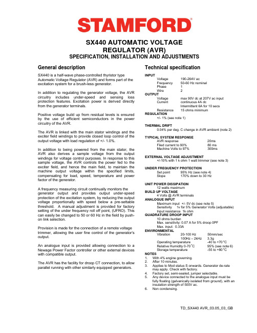
DESIGN DETAILTD_SX440 AVR_03.05_03_GBSX440 AUTOMATIC VOLTAGEREGULATOR (AVR)SPECIFICATION, INSTALLATION AND ADJUSTMENTSGeneral descriptionTechnical specificationSX440 is a half-wave phase-controlled thyristor type Automatic Voltage Regulator (AVR) and forms part of the excitation system for a brush-less generator.In addition to regulating the generator voltage, the AVR circuitry includes under-speed and sensing loss protection features. Excitation power is derived directly from the generator terminals.Positive voltage build up from residual levels is ensured by the use of efficient semiconductors in the power circuitry of the AVR.The AVR is linked with the main stator windings and the exciter field windings to provide closed loop control of the output voltage with load regulation of +/- 1.0%.In addition to being powered from the main stator, the AVR also derives a sample voltage from the output windings for voltage control purposes. In response to this sample voltage, the AVR controls the power fed to the exciter field, and hence the main field, to maintain the machine output voltage within the specified limits, compensating for load, speed, temperature and power factor of the generator.A frequency measuring circuit continually monitors thegenerator output and provides output under-speed protection of the excitation system, by reducing the output voltage proportionally with speed below a pre-settable threshold. A manual adjustment is provided for factory setting of the under frequency roll off point, (UFRO). This can easily be changed to 50 or 60 Hz in the field by push-on link selection.Provision is made for the connection of a remote voltage trimmer, allowing the user fine control of the generator's output.An analogue input is provided allowing connection to a Newage Power Factor controller or other external devices with compatible output.The AVR has the facility for droop CT connection, to allow parallel running with other similarly equipped generators.INPUTVoltage 190-264V ac Frequency 50-60 Hz nominal Phase 1 Wire 2 OUTPUT Voltage max 90V dc at 207V ac input Current continuous 4A dc Intermittent 6A for 10 secs Resistance 15 ohms minimum REGULATION +/- 1% (see note 1)THERMAL DRIFT 0.04% per deg. C change in AVR ambient (note 2)TYPICAL SYSTEM RESPONSE AVR response 20ms Filed current to 90% 80 ms Machine Volts to 97% 300msEXTERNAL VOLTAGE ADJUSTMENT +/-10% with 1 k ohm 1 watt trimmer (see note 3)UNDER FREQUENCY PROTECTION Set point 95% Hz (see note 4) Slope 170% down to 30 HzUNIT POWER DISSIPATION 12 watts maximum BUILD UP VOLTAGE 4 Volts @ AVR terminals ANALOGUE INPUT Maximum input +/- 5V dc (see note 5) Sensitivity 1v for 5% Generator Volts (adjustable) Input resistance 1k ohm QUADRATURE DROOP INPUT 10 ohms burden Max. sensitivity: 0.07 A for 5% droop 0PF Max. input: 0.33A ENVIRONMENTAL Vibration 20-100 Hz 50mm/sec 100Hz – 2kHz 3.3gOperating temperature -40 to +70 oCRelative Humidity 0-70 oC95% (see note 6) Storage temperature -55 to +80 oC NOTES1. With 4% engine governing.2. After 10 minutes.3. Applies to Mod status S onwards. Generator de-ratemay apply. Check with factory.4. Factory set, semi-sealed, jumper selectable.5. Any device connected to the analogue input must befully floating (galvanically isolated from ground), with an insulation strength of 500V ac. 6. Non condensing.DESIGN DETAILTD_SX440 AVR_03.06_03_GBThe main functions of the AVR are:Potential Divider and Rectifier takes a proportion of the generator output voltage and attenuates it. The potential divider is adjustable by the AVR Volts potentiometer and external hand trimmer (when fitted). The output from the droop CT is also added to this signal. An isolating transformer is included allowing connection to various winding configurations. A rectifier converts the a.c. input signal into d.c. for further processing.The Sensing Loss Detector is an electronic changeover switch, which normally connects the Amplifier (Amp) to the Voltage Sensing input and automatically changes over to the Power input when the normal sensing voltage is lost.The DC Mixer adds the Analogue input signal the Sensing signal.The Amplifier (Amp) compares the sensing voltage to the Reference Voltage and amplifies the difference (error) to provide a controlling signal for the power devices. The Ramp Generator and Level Detector and Driver infinitely control the conduction period of the Power Control Devices and hence provides the excitation system with the required power to maintain the generator voltage within specified limits.The Stability Circuit provides adjustable negative ac feedback to ensure good steady state and transient performance of the control system.The Low Hz Detector measures the period of each electrical cycle and causes the reference voltage to be reduced approximately linearly with speed below a presettable threshold. A Light Emitting Diode gives indication of underspeed running.The Synchronising circuit is used to keep the Ramp Generator and Low Hz Detector locked to the generator waveform period.The Low Pass Filter prevents distorted waveforms affecting the operation of the AVR control circiutPower Control Devices vary the amount of exciter field current in response to the error signal produced by the Amplifier.Suppression components are included to prevent sub cycle voltage spikes damaging the AVR components and also to reduce the amount of conducted noise on the generator terminals..The Power Supply provides the required voltages for the AVR circuitry.Hand TrimmerAnalogue InputDroopFITTING AND OPERATINGTD_SX440 AVR _03.06_03_GBSUMMARY OF AVR CONTROLSCONTROL FUNCTIONDIRECTIONVOLTS TO ADJUST GENERATOR OUTPUT VOLTAGE CLOCKWISE INCREASES OUTPUT VOLTAGE STABILITY TO PREVENT VOLTAGE HUNTING CLOCKWISE INCREASE THE DAMPING EFFECT UFRO TO SET THE UFRO KNEE POINTCLOCKWISE REDUCES THE KNEE POINT FREQUENCYDROOP TO SET THE GENERATOR DROOP TO 5% AT 0PF CLOCKWISE INCREASES THE DROOPVTRIMTO OPTIMISE ANALOGUE INPUT SENSITIVITYCLOCKWISE INCREASES THE GAIN OR SENSITIVITYADJUSTMENT OF AVR CONTROLSVOLTAGE ADJUSTMENTThe generator output voltage is set at the factory, but can be altered by careful adjustment of the VOLTS control on the AVR board, or by the external hand trimmer if fitted. Terminals 1 and 2 on the AVR will be fitted with a shorting link if no hand trimmer is required.CAUTION Do not increase the voltage above the rated generator voltage. If in doubt, refer to the rating plate mounted on the generator case.CAUTION Do not ground any of the hand trimmer terminals as these could be above earth potential. Failure to observe this could cause equipment damage.If a replacement AVR has been fitted or re-setting of the VOLTS adjustment is required, proceed as follows:CAUTION1. Before running generator, turn the VOLTS control fully anti-clockwise.2. Turn remote volts trimmer (if fitted) to midway position.3. Turn STABILITY control to midway position.4. Connect a suitable voltmeter (0-300V ac) across line to neutral of the generator.5. Start generator set, and run on no load at nominal frequency e.g. 50-53Hz or 60-63Hz.6. If the red Light Emitting Diode (LED) is illuminated, refer to the Under Frequency Roll Off (UFRO) adjustment.7. Carefully turn VOLTS control clockwise until rated voltage is reached.8. If instability is present at rated voltage, refer to stability adjustment, then re-adjust voltage if necessary.9. Voltage adjustment is now completed.FITTING AND OPERATINGTD_SX440 AVR_03.06_04_GBBarnack Road • Stamford • Lincolnshire • PE9 2NB Tel: 00 44 (0)1780 484000 • Fax: 00 44 (0)1780 484100© 2006 Cummins Generator Technologies Limited.Printed in England.STABILITY ADJUSTMENTThe AVR includes a stability or damping circuit to provide good steady state and transient performance of the generator.The correct setting can be found by running the generator at no load and slowly turning the stability control anti-clockwise until the generator voltage starts to become unstable.The optimum or critically damped position is slightly clockwise from this point (i.e. where the machine volts are stable but close to the unstable region).OPTIMUM RESPONSE SELECTIONThe stability selection ‘jumper’ should be correctly linked, A-B, B-C or A-C at the bottom of the board for the frame size of the generator, (see drawing).UNDER FREQUENCY ROLL OFF (UFRO) ADJUSTMENTThe AVR incorporates an underspeed protection circuit which gives a volts/Hz characteristic when the generator speed falls below a presettable threshold known as the "knee" point.The red Light Emitting Diode (LED) gives indication that the UFRO circuit is operating.The UFRO adjustment is preset and sealed and only requires the selection of 50 / 60Hz using the jumper link.For optimum setting, the LED should illuminate as the frequency falls just below nominal, i.e. 47Hz on a 50Hz system or 57Hz on a 60Hz system.DROOP ADJUSTMENTGenerators intended for parallel operation are fitted with a quadrature droop C.T. which provides a power factor dependent signal for the AVR. The C.T. is connected to S1, S2 on the AVR.The DROOP adjustment is normally preset in the works to give 5% voltage droop at full load zero power factor.Clockwise increases the amount of C.T. signal injected into the AVR and increases the droop with lagging power factor (cos Ø). With the control fully anti-clockwise there is no droop.TRIM ADJUSTMENTAn analogue input (A1 A2) is provided to connect to the Newage Power Factor Controller or other devices. It is designed to accept dc signals up to +/- 5 volts.CAUTION Any devices connected to this input must be fully floating and galvanically isolated from ground, with an insulation capability of 500 Vac. Failure to observe this could result in equipment damage.The dc signal applied to this input adds to the AVR sensing circuit. A1 is connected to the AVR 0 volts. Positive on A2 increases excitation. Negative on A2 decreases excitation.The TRIM control allows the user to adjust the sensitivity of the input. With TRIM fully anti-clockwise the externally applied signal has no effect. Clockwise it has maximum effect.Normal setting is fully clockwise when used with a Newage Power Factor Controller.。
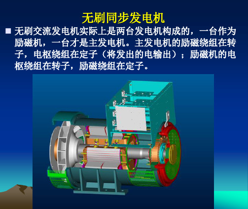
斯坦福无刷发电机励磁介绍
底脚
A.V.R. 装在 A.V.M上
出线盒
P.M.G P.M.G 转子 定子
一、斯坦福发电机的结构 1.主定子
一、斯坦福发电机的结构 2. 转子
过渡轮毂 过渡盘片
单轴承主转子总成
发电机的驱动端由发动机的飞轮支撑.
励磁转子
轴承 (密封)
主转子
风叶
轴承 (密封)
轴
PMG转子 (建议用于 UC 机整)流模块
康明斯/斯坦福凸极同步发电机
STAMFORD发电机
产品型号识别
I
型号
控制系统
MX341/ MX321 SX440/ SX421
陆用 船用
机座号
极数
轴承数
铁芯长度
STAMFORD发电机
产品型号的识别
型号
轴的中心高 (厘米)
M - 船用 I - 陆用l
轴承数 极数
铁芯长度
控制系统
3 - PMG / AVR
7 8
X XX
永磁机励磁无刷发电机工作原理
• 发电机工作时,永磁机定子输出P2、P3、P4,电压值约 为130-150VAC之间,此电压值输入到稳压板(AVR)的 P2、P3、P4 端子,经AVR内部的二极管予以整流后, 输出×、××(空载时约8-9VDC)到电球的励磁机定子 线圈,励磁机转子线圈感应出交流电,经安装在励磁机转 子线圈上的6个二极管整流出直流。此直流电流到主转子 线圈,主转子线圈在旋转状态下产生一个磁场,主定子线 圈感应出交流电(如400VAC输出)。
MX321
MX321
通过检测发电机主绕组的 电压,以控制提供给 励磁机定子以及主 转子的电流,来维持发电机输 出电压介于指定的范围内,并补偿负载、转速、 温度及发电机的功率因数。而三相的RMS 检测可 提供更准确的电压调节,设有可 调节的缓慢起动 电路可控制发电机输 出电压的平滑建立。
沃尔沃柴油发电机组说明书

All specifications and design are subject to change without noticeOverall Dimensions & Weights - Open SetLength (L) = 3420mm [132in]Width (W) = 1140mm [45in]Height (H) = 2020mm [80in]Dry Weight (inc oil) = 3657kg [8101lb]Operating Weight = 4241kg [9349lb]989492904000 Hz 8000 Hz 10593101Typical Open Generator Sound Pressure Level at 1m, Free Field (dB)125 Hz 400Key Features:● Water cooled Volvo diesel engine with ECU/CANBus ● Single bearing CGT Stamford alternator ● Radiator with pressure cap and drain point ● Fully guarded engine-driven fan● Fully welded steel skid base with lifting points ● Integral fuel tank with filler cap and gauge ● Heavy duty rubber anti-vibration mountings ● 24V starter batteries and connecting cables● Separate engine-driven battery charging alternator● Spin on oil and fuel filters and dry type air filter element ● Industrial silencer (15dBA reduction) supplied loose ● Auto Start control system with digital instrumentation ● Main line circuit breaker ● Factory Test Certificate● Operation & Maintenance Manual● Wide range of optional extra features available440/254416/2405753206081054400350220/1274001002000 Hz 10063 Hz Overall dBA400320438350250 Hz 500 Hz 1000 Hz Definition of Ratings & Reference ConditionsPrime Power (PRP) is the nominal output continuously available, where the average load (variable) does not exceed 70% of the prime power rating. 10% overload is available for a maximum of 1 hour in 12 hours of operation.Standby Power (LTP ) is the maximum output available, for up to 500 hours per year, where the average load does not exceed 70% of the standby power rating. No overload is available.Standard Reference Conditions: air inlet temperature 25°C (77°F), barometric pressure 100kPa, [110m (361ft) altitude], 30% relative humidity.Note: The above ratings may be subject to derate at different operating conditions. Please see the Derate Guidelines on the Broadcrown website.All power ratings and reference conditions in accordance with ISO 8528-1 and ISO 3046-1.1149240/138320438350527320438Technical DataMay 2013Generator Model: VolvoTAD 1352GE CGT Stamford HCI 444BCV 350-60 T3/FVoltage 480/277400kWe kVA Amps 43835060 HzEmissionsEPA Tier III Flex CompliantPower FactorCos Φ = 0.83-Phase350320kWe kVA 438RatingsPrime Power (PRP)Standby Power (LTP)HL WSI Units[US Units]Engine Speed r/min [rpm]Gross Power kWm [bhp]363487395530Fan Power kWm [bhp]1925.51925.5Net PowerkWm [bhp]344461376504Emissions Certification Altitude Capabilitym[ft.]1000330010003300Cylinders / TypeAspiration / Charge CoolingGoverning / Engine Management Bore / Stroke mm [in.]Cubic Capacity litres [cu.in.]BMEPkPa [psi]18942752061299Fuel Consumption at 100% Power litres/h [gal/h]87.223.096.325.4Fuel Consumption at 75% Power litres/h [gal/h]66.717.672.919.3Fuel Consumption at 50% Power litres/h [gal/h]46.412.349.513.1Total fuel flowlitres/h [gal/h]Standard Fuel Tank Capacitylitres [gal]Engine Air Flowm³/s [cfm]0.4339180.433918Maximum Air Intake Restriction (used filter)kPa [inWG]Exhaust Gas Flowm³/s [cfm] 1.0452214 1.1282391Exhaust Gas Temperature°C [°F]470878535995Maximum Exhaust Back Pressure kPa [inWG]Typical Exhaust Pipe Diameter mm [in.]Radiator Cooling Air Flowm³/s [cfm]Max Restriction to Cooling Air Flow Pa [inWG]Max Radiator Air-On Temperature °C [°F]Maximum Coolant Temperature °C [°F]Coolant Capacity - Engine Only litres [gal]Total Coolant Capacitylitres [gal]Total Oil Capacity incl Filterslitres [gal]Typical Oil Pressure at Rated SpeedkPa [psi]Typical Oil Consumption (>250hrs Operation)litres/h [pt/h]Heat Rejection to Engine Cooling Water kW [btu/min]164933517710075Heat Rejection to Charge CoolerkW [btu/min]834724874952Heat Radiated From Engine (Typical)kW[btu/min]84559512Electrical System Voltage Battery TypeBattery Capacity SAE CCASI Units[US Units]ManufacturerModel (may vary with voltage)Operating Temperature °C[°F]40[104]27[81]Coupling / No. of Bearings Phase / Poles / Winding Type Power Factor ExcitationInsulation System AVR TypeVoltage RegulationAll specifications and design are subject to change without noticeElectronic Governor / ECU / CANBusTurbocharged / Air to Air6 cyl / Inline / 4-stroke Direct / Single Bearing Alternator55131810F u e l A i r71118831205AS 440± 1.0%Self exited StandbyPrimeG e n e r a lEngine & Cooling SystemVolvo TAD 1352GE1800BCV 350-60 T3/F5.16 /6.22773131 / 15812.78P e r f o r m a n c eT3/FMay 2013G e n e r a l D a t a84412StandbyE x h a u s tC o o l i n g T h e r m a l O i lE l e c V 201029.540Class H 3-Phase / 4-Pole / Winding 311445A0.22 (series) 656Cos Φ = 0.8HCI 444 E HCI 444 ECummins Generator Technologies - Stamford240.48PrimeCGT Stamford HCI 4442165.336140911.21162946.710200[ ] [ [ [ [ [ [ [ [ [ [ [ [ [ [ [ [ [ [ [ [ [ [ [ [ [ [ [ [ [ [ [ ] ]] ]] ] ] ] ] ]]]] ]] ] ] ] ] ] ] ]] ] ]]] ] ] ]] [ ] ] [ [ ][ ]][ [ ] [ ][ ] ][ ] [ ][STANDARD CONTROL SYSTEM BC 7310 Digital Auto StartThe standard control system for this model is BC 7310 (photo), based on the DeepSea Electronics DSE7310 Digital Auto Start controller.This provides for the manual and automatic remote start of the generator, togetherwith full CANBus implementation for the control and protection of the engine via theECU. LCD digital display of :▪ Coolant temperature with high temperature alarm and shutdown▪ Oil pressure with low pressure alarm and shutdown▪ Oil temperature, engine operating hours, battery charge volts and amps▪ Volts, with Under/Over Volts protection▪ Amps, with Over Current protection▪ Frequency, kW, kVA, Power FactorAlso featuring :▪ Full RS485 Telemetry implementation▪ Automatic cool-down timer function▪ Emergency Stop button▪ Ample auxiliary inputs/outputs for optional features▪ Optional (shown) - battery charger and door mounted illuminated switch.CONTROL SYSTEM OPTIONSThe BC 7320 control system (just the DSE7320 module is shown here) has an identical featureset to the BC 7310 but with the addition of full AMF functionality with integrated mainsmonitoring.Finally, BC 8610 & BC 8620 control systems provide the same features asBC 7310 & BC 7320 respectively, plus :▪ BC 8610 - Set-to-Set Synchronisation▪ BC 8620 - Single Set-to-Mains Supply Synchronisation withintegrated mains monitoringFor Multi Set-to-Mains synchronisation, each set requires BC 8610 with theaddition of one mains monitoring panel BC 8660 (not illustrated).See the Synchronisation Guidelines for further details.All designs and specifications subject to change without noticeLxWxHdB(A) at 1m [3ft]dB(A) at 7m [23ft]IntegralBunded5200[204]x 1740[68]x2200[86]2400[5291]7868985[260]895[236]OptionalOPTIONAL ACOUSTIC ENCLOSURE Canopy 5[ Indicative weight of canopy additional to open setTypical SPL is a mean level, measured in free field conditions, with no contributory background noise.KEY OPTIONS (Open Set)Dimensions mm [in]Additional Weight kg [lbs]*Typical Sound Pressure Levelat Standby Power Fuel Tank Capacity Litres [US gal]Single Point LiftThe optional acoustic enclosure for this model is Canopy 5R , suitable for operation in harsh outdoor environmments whilst providing excellent security and acoustic performance. The steel canopy is of fully welded construction with a two-pack polyurethane egg-shell finish in RAL9001 white. The baseframe is finished in RAL9005 satin finish black.Acoustically, the canopy is designed to meet the requirements ofEU Legislation 2000/14/EC, achieved by extensive use of rock wool andperforated zintec steel lining, together with efficient management of cooling air. Exhaust noise is minimised by a unique high performance exhaust silencer, mounted within the baseframe.A steel fuel tank with filler, gauge and accessory points, is integrated within the baseframe. Alernatively, a bund with separate fuel tank can be provided where this is required.Other key features include :- Side-opening doors with retainers for good service access - Control panel viewing window - External service access panels- Heavy duty locks on all doors for total security - Weather cap on exhaust discharge- Emergency Stop button relocated to canopy exterior - Lifting and holding down points on baseframe - Optional single roof lifting point.Engine & Cooling :- Oil and coolants drains extended to edge of baseframe - Manual lub oil drain pump - Coolant heater- Medium duty air cleaner - Exhaust manifold guardsFuel System :- Baseframe with integral bund and drop-in fuel tank - Fuel filter/separator- Low fuel level switch (single point)- Fuel level switch (four point)- Manual fuel transfer pump- Pumped/gravity fuel transfer system Alternator :- Anti-condensation heater - Quadrature droop kit - Alternative AVR- Thermistor probes and controlsExhaust System :- Residential silencer - Critical silencer- Flange/connection kitPlease refer to Broadcrown Sales Department for full details of these and other optionsAll designs and specifications subject to change without notice。
发电机常用英文

RUN运转灯,绿色表示机组在运转PRE LOW OIL PRES低油压预报警康明斯七灯机中出现,低油压保护分两级,先预报警,表示油压低了要处理,预报警不会停机(SHUT DOWN),但如不处理,油压继续低就会停机,处理后此黄灯就不亮了。
3、PRE HIGH ENG TEMP:高水温预报警道理和上边一样,将水温换过来,全新康明斯七灯机水温上升到100度就预报警,如不处理水温继续升到105度就停机。
4、OVERSPEED:超速保护(飞车)常用兔子来表示一般柴油机转速为1500转/分,超过10%即1650转/分就保护,会立即停机,红色灯亮。
我们的控制器501K有此功能(BE20就没有此功能)。
501K的超速保护信号有两种,一是接测速传感器,用其信号;二是接入220V发电机电压利用电压的频率作为输入信号。
5、LO OIL PRESS(LOW OIL PRESSURE):低油压康明期七灯机中此为停机灯,红色,表示油压过低。
6、HI ENG TEMP(HIGH WATER TEMPRETURE):发动机高水温康明斯七灯机中此为停机灯,红色,表示水温太高。
7、OVERCRANK:过盘车(起动失败)此灯在遥控起动时才会出现,遥控(REMOTE)起动是接触式(两条线接通),如正常运转时此灯亮可能电路板某处坏了,我们不用遥控起动功能。
8、AMMETER:电流表(AC AMPERES)交流电流表康明斯机还有一个转换开关UPPER SCALE表示看上边的刻度,LOWER SCALE看下边的刻度,分大小机选择。
通常电流表范围是机组功率的2倍,250千瓦机用500安培的电流表。
9、VOLTMETER:电压表(AC VOLTS)交流电压表。
10、THREE PHESE:三相电流(电压)转换开关配合8、9两个表来看三相电流表或电压。
11、FREQUENCY:频率表我们社会主义国家常用50赫兹(HERTZ)的频率,机组在1500转/分运转。
康明斯柴油机的常见故障原因
一、康明斯柴油机的常见故障原因(一)柴油机冒黑烟1)涡轮增压器工作失郊;2)气门组件密封不良;3)喷油器或高压油泵精密偶件工作失郊;4)凸轮轴组件磨损过度;5)中冷器过脏、入气量不足;6)喷油器胶圈密封不良;7)气缸组件拉缸;8)柴油质量不良。
(二)柴油机冒白烟1)喷油器或高压油泵精密偶件失郊;2)柴油机烧机油(即增压器烧机油);3)气门导管及气门磨损过度,机油漏入气缸;4)柴油中有水;5)喷油气缸套漏水入气缸;6)活塞环磨损过度或油环装反,气缸烧机油。
(三)在高负载时,排烟管及增压器发红1)喷油器或高压油泵精密偶件工作失郊;2)凸轮轴、随动臂组件、摇臂组件磨损过度;3)中冷器过脏、入气量不足;4)增压器工作失郊;5)气门组件密封不良。
(四)柴油机工作时功率亏损较大1)气缸组件磨损过大;2)喷油器或高压油泵精密偶件工作失郊;3)PT油泵工作失郊;4)正时机构工作不良;5)增压器工作失郊;6)中冷器过脏;7)气门组件密封不良;8)柴油格、空气格过脏。
(五)柴油机机油压力过低1)轴瓦和曲轴的配合间隙过大,即轴瓦和曲轴磨损过大;2)各种衬套和轴系磨损过大;3)冷却喷咀或机油管漏油;4)机油泵工作失郊;5)油压传感器失郊;6)机油冷却器过脏导致油温过高;7)机油品质不良。
(六)柴油机水温过高1)水泵损坏;2)节温器损坏;3)风扇皮带,水泵皮带过松;4)水箱过脏。
(内部或外部)(七)柴油机出现烧瓦现象1)机油泵工作失郊;2)轴瓦间隙过大,引起油压过低;3)柴油机缺水而出现高温;4)机油格堵塞;5)机油品质不良。
(八)柴油机下浊气大现象或有白烟从下浊气管排出1)气缸组件磨损过大;2)油底壳有水;(缸盖破裂,喷油器铜套水,缸套烂穿,缸套胶圈漏水,缸体漏水)3)有拉缸现象。
(九)柴油机转速不稳1)柴油机有功率亏损过大的故障;2)PT泵的电子执行器磨损过度以及PT泵内部机件故障;3)EFC电子调速板工作失郊;4)测速磁头损坏;5)柴油格过脏;6)柴油管道漏气。
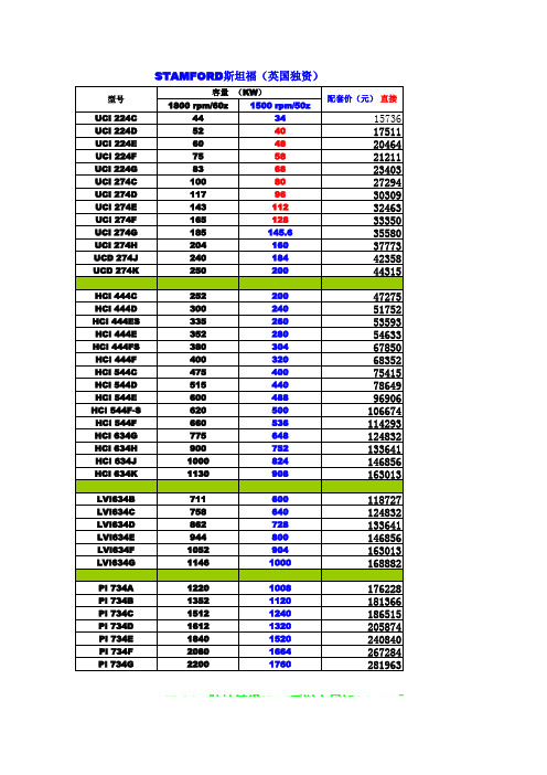
斯坦福发电机报价2015
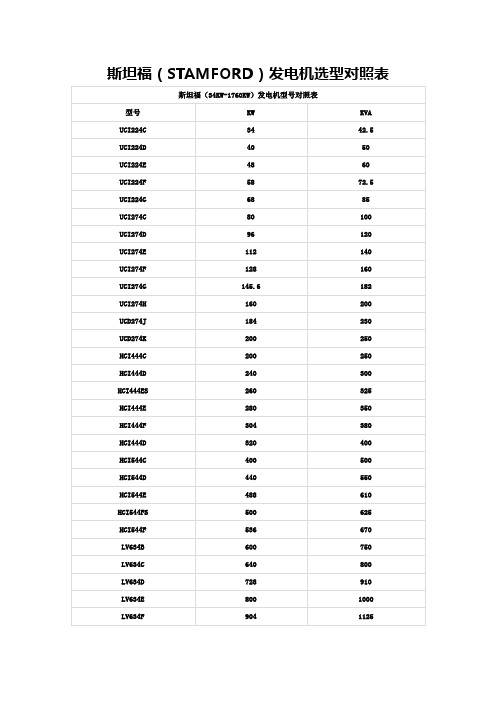
型号 UCI 224C UCI 224D UCI 224E UCI 224F UCI 224G UCI 274C UCI 274D UCI 274E UCI 274F UCI 274G UCI 274H UCD 274J UCD 274K HCI 444C HCI 444D HCI 444ES HCI 444E HCI 444FS HCI 444F HCI 544C HCI 544D HCI 544E HCI 544F-S HCI 544F HCI 634G HCI 634H HCI 634J HCI 634K LVI634B LVI634C LVI634D LVI634E LVI634F LVI634G PI 734A PI 734B PI 734C PI 734D PI 734E PI 734F PI 734G 容量 (KW) 1800 rpm/60z 44 52 60 75 83 100 117 143 165 185 204 240 250 252 300 335 352 380 400 475 515 600 620 660 775 900 1000 1130 711 758 862 944 1052 1146 1220 1352 1512 1612 1840 2080 2200 1500 rpm/50z 34 40 48 58 68 80 96 112 128 145.6 160 184 200 200 240 260 280 304 320 400 440 488 500 536 648 752 824 908 600 640 728 800 904 1000 1008 1120 1240 1320 1520 1664 1760 配套价(元) 直接
7458 8044 9341 10005 10275 10669 11262 11657 12680 14071 14903 15331
斯坦福STAMFORD发电机简介
无锡新时代交流发电机业务情况
百万人民币
700 600 500 400 300 200 100 0 1997 1998 1999 2000 2001 2002 2003 2004 2005 2006
无锡新时代业务情况
台 45000
40000 35000 30000 25000 20000 15000 10000 5000 0 1997 1999 2001 2003 2005 West
斯坦福(Stamford) 机座号8
低压 1800kW - 2000kW (50Hz)
中压 1400kW - 1600kW (50Hz) 高压 1000kW - 1600kW (50Hz) 永磁机励磁为标准配置 VPI Global 浸漆系统
AVR 系 统
机座/ AVR BC16 SA465 SA465 SX460
4 - 2500kW
2、4、6 极
弗里德列(美国)
15,900m2
2、4 极
407
无锡独资企业 (中国) 艾哈迈德讷格尔 合资企业(印度) 奥克姆(马肯)
6 - 1000kW
2或4 极
3,750m2 450 200 - 825kW
4极
1,400m2
48
0.6 - 7.5kW 960m2 28
2极
31.01.95
斯坦福(Stamford) BC16 和 BC18
6.5kW 至 32kW (50Hz)
自励或永磁机励磁 AVR 有两种安装位置
斯坦福(Stamford) UC224 和 UC274
34kW 至 160kW (50Hz)
自励或永磁机励磁 AVR 有两种安装位置
海德馨牌移动应急电源车介绍及应用

海德馨牌移动应急电源车介绍及应用移动应急电源车( 下称电源车) 以其具有移动快捷、低噪声运行、操作简便、全天候工作的特点, 广泛应用于停电会产生严重影响的电力、通信、抢险和军事等场所, 作机动应急备用电源。
由龙岩市海德馨汽车有限公司开发的移动应急电源车, 在结构设计、使用功能、操作控制、噪声消减、安全可靠性等方面都具有突出的技术优势, 在保证各市重大活动的安全供电和应急供电方面发挥了重要作用。
一电源车的基本技术性能介绍1. 1.车载系统1) 车速。
电源车选用东风、五十铃、依维柯等汽车的发动机与底盘, 移动速度可达100 km/ h以上。
2) 载重量。
在考虑应急电源的全部设备重量总和的基础上, 车辆的载重量还留有10% ~ 15% 不等的裕度。
3) 人性化操作和维修空间。
机组开机、关机操作和仪表观察时, 操作人员可在车内操作间进行。
车厢内留有较大空间并装有附属设施, 以方便机组的维修和保养。
操作间装有电脑,空调,沙发等设施,在野外恶劣环境保电时可供操作员有良好工作环境。
4) 安全措施。
车厢内门口处配有消防灭火器, 车厢内配有烟感报警器、交直流防爆照明灯和应急灯, 还有方便使用的接地钎和接地线, 以有效保证电源车的安全。
选用智能灭火系统,可无人值守。
1. 2.柴油发电机组1) 柴油机组选用美国CAT、英国威尔信、康明斯等国际知名品牌。
2) 发电机采用国际知名品牌Stamford 无刷自励交流同步发电机, 采用AVR 自动电压调节。
3) 发电机组安装底座为机底油箱结构。
油箱储油能满足机组运行8 h 以上的要求。
4) 发电机组的功率有20 kW~ 2000 kW 多种规格。
带有缸套水预热和启动蓄电池浮充装置, 随时处于备用状态, 机组启动后能在12 s 内带满负载, 完全满足应急快速供电的要求。
1. 3.控制和操作系统1)机组配套的控制屏提供手动启动机组的功能, 可自动监测机组的运行, 提供机组的保护功能, 控制屏面板上提供机组运行全部参数的指示表, 便于直观地查看机组状态。
sx460,STAMFORD,sx460,英文说明书

SX460 AUTOMATIC VOLTAGEREGULATOR (AVR)SPECIFICATION, INSTALLATION AND ADJUSTMENTS General description Technical specificationSX460 is a half-wave phase-controlled thyristor type Automatic Voltage Regulator (AVR) and forms part of the excitation system for a brush-less generator.In addition to regulating the generator voltage, the AVR circuitry includes under-speed and sensing loss protection features. Excitation power is derived directly from the generator terminals.Positive voltage build up from residual levels is ensured by the use of efficient semiconductors in the power circuitry of the AVR.The AVR is linked with the main stator windings and the exciter field windings to provide closed loop control of the output voltage with load regulation of +/- 1.0%.In addition to being powered from the main stator, the AVR also derives a sample voltage from the output windings for voltage control purposes. In response to this sample voltage, the AVR controls the power fed to the exciter field, and hence the main field, to maintain the machine output voltage within the specified limits, compensating for load, speed, temperature and power factor of the generator.A frequency measuring circuit continually monitors the generator output and provides output under-speed protection of the excitation system, by reducing the output voltage proportionally with speed below a pre-settable threshold. A manual adjustment is provided for factory setting of the under frequency roll off point, (UFRO). This can easily be changed to 50 or 60 Hz in the field by push-on link selection.Provision is made for the connection of a remote voltage trimmer, allowing the user fine control of the generator's output. INPUTVoltage Jumper selectable95-132V ac or190-264VacFrequency 50-60 Hz nominalPhase 1OUTPUTVoltage max 90V dc at 207V ac inputCurrent continuous 4 A dcIntermittent 6 A for 10 secsResistance 15 ohms minimumREGULATION+/- 1.0% (see note 1)THERMAL DRIFT0.05% per deg. C change in AVR ambient (note 2)TYPICAL SYSTEM RESPONSEAVR response 20 msFiled current to 90% 80 msMachine Volts to 97% 300 msEXTERNAL VOLTAGE ADJUSTMENT+/-10% with 1 k ohm 1 watt trimmer (see note 3)UNDER FREQUENCY PROTECTIONSet point 95% Hz (see note 4)Slope 170% down to 30 HzUNIT POWER DISSIPATION10 watts maximumBUILD UP VOLTAGE4 Volts @ AVR terminalsENVIRONMENTALVibration 20-100Hz 50mm/sec100Hz – 2kHz 3.3gOperating temperature -40 to +70°CRelative Humidity 0-70°C 95% (see note 5)Storage temperature -55 to +80°CNOTES1. With 4% engine governing2. After 10 minutes.3. Applies to Mod status F onwards. Generator de-rate mayapply. Check with factory.4. Factory set, semi-sealed, jumper selectable5. Noncondensing.DESIGN DETAIL The main functions of the AVR are:Potential Divider and Rectifier takes a proportion of the generator output voltage and attenuates it. This input chain of resistors includes the range potentiometer and hand trimmer which adjust the generator voltage. A rectifier converts the a.c. into d.c. for further processing.The Amplifier (Amp) compares the sensing voltage to the Reference Voltage and amplifies the difference (error) to provide a controlling signal for the power devices. The Ramp Generator and Level Detector and Driver infinitely control the conduction period of the Power Control Devices and hence provides the excitation system with the required power to maintain the generator voltage within specified limits.The Stability Circuit provides adjustable negative ac feedback to ensure good steady state and transient performance of the control system.The Low Hz Detector measures the period of each electrical cycle and causes the reference voltage to be reduced approximately linearly with speed below a presettable threshold. A Light Emitting Diode gives indication of underspeed running.The Synchronising circuit is used to keep the Ramp Generator and Low Hz Detector locked to the generator waveform period.The Low Pass Filter prevents distorted waveforms affecting the operation of the AVR.Power Control Devices vary the amount of exciter field current in response to the error signal produced by the Amplifier.Suppression components are included to prevent sub cycle voltage spikes damaging the AVR components and also to reduce the amount of conducted noise on the generator terminals.The Power Supply provides the required voltages for the AVR circuitry.Remove link to connect a remote voltage trimmerLink for 110V/120V AVR inputSUMMARY OF AVR CONTROLSCONTROL FUNCTION DIRECTIONVOLTS TO ADJUST GENERATOR OUTPUT VOLTAGE CLOCKWISE INCREASES OUTPUT VOLTAGE STABILITY TO PREVENT VOLTAGE HUNTING CLOCKWISE INCREASE THE DAMPING EFFECTUFRO TO SET THE UFRO KNEE POINT CLOCKWISE REDUCES THE KNEE POINTFREQUENCYADJUSTMENT OF AVR CONTROLSVOLTAGE ADJUSTMENTThe generator output voltage is set at the factory, but can be altered by careful adjustment of the VOLTS control on the AVR board, or by the external hand trimmer if fitted. Terminals 1 and 2 on the AVR will be fitted with a shorting link if no hand trimmer is required. Terminals 3 and 4 are linked only for special low voltage applications.CAUTION Do not increase the voltage above the rated generator voltage. If in doubt, refer to the rating plate mounted on the generator case.CAUTION Do not ground any of the hand trimmer terminals as these could be above earth potential. Failure to observe this could cause equipment damage.If a replacement AVR has been fitted or re-setting of the VOLTS adjustment is required, proceed as follows: CAUTION1. Before running generator, turn the VOLTS control fully anti-clockwise.2. Turn remote volts trimmer (if fitted) to midway position.3. Turn STABILITY control to midway position.4. Connect a suitable voltmeter (0-300V ac) across line to neutral of the generator.5. Start generator set, and run on no load at nominal frequency e.g. 50-53Hz or 60-63Hz.6. If the red Light Emitting Diode (LED) is illuminated, refer to the Under Frequency Roll Off (UFRO) adjustment.7. Carefully turn VOLTS control clockwise until rated voltage is reached.8. If instability is present at rated voltage, refer to stability adjustment, then re-adjust voltage if necessary.9. Voltage adjustment is now completed.TD_SX460 AVR GB_04.05_06_GB Barnack Road • Stamford • Lincolnshire • PE9 2NB Tel: 00 44 (0)1780 484000 • Fax: 00 44 (0)1780 484100© 2005 Cummins Generator Technologies Limited.STABILITY ADJUSTMENTThe AVR includes a stability or damping circuit to provide good steady state and transient performance of the generator.The correct setting can be found by running the generator at no load and slowly turning the stability control anti-clockwise until the generator voltage starts to become unstable.The optimum or critically damped position is slightly clockwise from this point (i.e. where the machine volts are stable but close to the unstable region).UNDER FREQUENCY ROLL OFF (UFRO) ADJUSTMENTThe AVR incorporates an underspeed protection circuit which gives a volts/Hz characteristic when the generator speed falls below a presettable threshold known as the "knee" point.The red Light Emitting Diode (LED) gives indication that the UFRO circuit is operating.The UFRO adjustment is preset and sealed and only requires the selection of 50 / 60Hz using the jumper link.For optimum setting, the LED should illuminate as the frequency falls just below nominal, i.e. 47Hz on a 50Hz system or 57Hz on a 60Hz system.。
斯坦福
符合标准:CE标准、GB755、BS5000、IEC60034-1
200KW康明斯系列柴油发电机组技术参数
柴油发电机组参数
输出功率:200KW
起动时间:5-6秒
起动电压:24V
额定电压:400/230V
功率因素:0.8(滞后)
波形失真率:≤5%
燃油消耗率:≤206g/kw.h
调速方式:电子调速
进气方式:涡轮增压
机油消耗率:≤1.1g/kw.h
排量:8.3L
气缸数:直列6缸
缸径×行程:114×135(mm)
冷却方式:闭式水冷
起动方式:24V直流电启动
润滑系容量:20L
功率:183KW
冲程:四冲程
润滑方式:压力和飞溅润滑
发电机参数(马拉松)
型号:MP-160-4
120KW康明斯系列柴油发电机组技术参数2014-01-06
140KW康明斯系列柴油发电机组技术参数2014-01-06
160KW康明斯系列柴油发电机组技术参数2014-01-06
200KW康明斯系列柴油发电机组技术参数2014-01-06
220KW康明斯系列柴油发电机组技术参数2014-01-06
稳定电压调整率:≤±1%
稳定频率调整率:≤1%
额定频率:50HZ
瞬态电压调整率:20%~-15%
瞬态频率调整率:≤10%~-7%
额定转速:1500 rpm
电压波动率:≤0.5%
频率波动率:≤0.5%
起动方式:直流电起动
负荷突变电压稳定时间:≤1S
负荷突变频率稳定时:间≤1S
机组重量:800kg
机组尺寸:1800×750×1200(mm×mm×mm)
威尔逊发电机组培训资料

威尔逊柴油发电机组培训资料深圳市鑫科动力设备有限公司官网: E-mail:*****************目录第一部分:柴油发电机组概况 (2)第二部分:发电机组基本结构和工作原理 (6)第三部分:威尔逊机组控制屏 (14)第四部分:威尔逊发电机组自动负载切换屏(ATS) (17)第五部分:威尔逊发电机组的使用 (23)第六部分:柴油发电机组并机系统介绍及操作 (26)第七部分:机组的维护保养 (31)第八部分:柴油发电机组安装与调试 (35)第九部分:柴油发电机组常见故障分析 (37)第十部分:柴油发电机技术管理制度 (49)第一部分:柴油发电机组概况随着我国通信事业的迅猛发展,通信手段不断现代化,各类通信设备不断更新,技术水平提高,各电信局(站)的装机容量不断扩大,各类通信设备都要求提供不间断、高质量稳定的供电电源。
尤其是现代通信设备的运行,除了要求本设备正常运行所用的各类电源之外,还要求保证现代通信设备运行的环境。
通信设备的运行所需的交流电源,主要由电力部门提供,但是,当遇到电力部门正常检修或电网故障而停电时,电信局(站)就必须依靠自备的柴油发电机组来发电,以保证通信设备所需交流电源供给。
由此可知,柴油发电机组是保障通信设备连续可靠、安全运行的重要设备。
柴油发电机组目前已广泛用于通信电源站。
柴油发电机组具有高强化程度、高可靠性、高稳定性等特点,由于有计算机参与自动控制与操作,所以柴油发电机组具有自动化程度高、低油耗、低排放、低噪声等优点。
一、威尔逊公司基本情况介绍英国威尔逊有限公司(F.G.Wilson)成立于1966年,是一家专业成套工业用柴油发电机组的制造企业。
经过近40年的发展,威尔逊公司已成为全欧洲最大规模的柴油发电机组生产厂家。
1998年,更与卡特彼勒公司合并,成为当今世界上最具规模的柴油发电机组生产厂家。
每年成套各种规格类型的柴油发电机组逾3万台(套),雄踞世界第一。
威尔逊柴油发电机组采用驰名世界的伯琼斯·劳斯莱斯(PERKINS。
- 1、下载文档前请自行甄别文档内容的完整性,平台不提供额外的编辑、内容补充、找答案等附加服务。
- 2、"仅部分预览"的文档,不可在线预览部分如存在完整性等问题,可反馈申请退款(可完整预览的文档不适用该条件!)。
- 3、如文档侵犯您的权益,请联系客服反馈,我们会尽快为您处理(人工客服工作时间:9:00-18:30)。
AVR AS440 DATASHEET1.Product description˖AS440 is a half wave phase controlled thyristor type AVR and forms part of the excitation system for a brushless generator.Technical specification2.Sensing input:Voltage Jumper selectable100-130 Vac 1 phase or190-264 Vac 1 phaseFrequency 50-60 Hz nominal3.Power Input:Voltage 100-264 V ac 1 phaseFrequency 50-60 Hz nominal4.Output:Voltage 82 V d.c. @ 200 V a.c.Current continuous 4A (see note 1).transient 7.5A for 10 secs.Resistance 15 ohms min(10 ohms min when inputvolts is less than 175 ac)5.Regulation:+/- 1.0% (see note 2)6.Thermal Drift:0.03% per deg. C change in AVR ambient (see note 3)7.Typical System Response: AVR response 20 msFiled current to 90% 80 msMachine Volts to 97% 300 ms8.External Voltage Adjustment: +/-10% with 1 k ohm 1 watt trimmer (see note 4)ed For:PartsDescriptionBC16/18 UC22/27 HC4/5 HC6/LV6 P7AVRSX460 SX440 SX440 MX341 MX341 SX440/AS440 AS440 AS440 MX321 MX321Ruitai Industry Co.,LtdAVR EA440-T DATASHEET1.Product description˖EA440 is a Self Excited Automatic Voltage RegulatorˈCompatible with Newage SX440DŽ2.Features:< ±1% RegulationCan Be Use In Parallel OperationAdjustable DIP, TRIM & DROOP FunctionUnder Frequency Roll Off ProtectionSensing Voltage Loss ProtectionUnder Frequency LED IndicatorSoft Start Voltage RampingRuitai Industry Co.,LtdSensing Input Voltage 190 ~ 264 VAC, 1 phase 2 wireFrequency 50/60H zSinglePhaseOutput Voltage Max. 90 VDC at 207 VACCurrent Continuous4AIntermittent 10 A for 10 sec.Resistance Min.15Voltage Regulation < ±1% (with 4% engine governing) Voltage Build-up Residual volts at AVR terminal > 5 VAC Thermal Drift 0.04% per °C change in AVR ambient Soft Start Ramping 2 sec.Unit Power Dissipation Max. 12 wattExternal Volts Adjustment ±8% with 1K O 1 watt trimmerUnder Frequency Protection (UFRO) Set point 95% HzSlope 170% down to 30 HzAnalogue Input Max. Input ±5 VDCSensitivity 1V for 5% generator voltsInput Resistance 1KDroop Input Burden 10Max sensitivity 0.07 A for 5% droop (PF=0)Max. input 0.33 Aed For:Parts Description BC16/18 UC22/27 HC4/5 HC6/LV6 P7AVRSX460 SX440 SX440 MX341 MX341 SX440/AS440 AS440 AS440 MX321 MX321Ruitai Industry Co.,LtdAVR SX440 DATASHEET1.Product description˖SX440 is a half-wave phase-controlled thyristor type Automatic Voltage Regulator (AVR) and forms part of the excitation system for a brush-less generator.2.Technical specificationa. INPUTVoltage 190-264V acFrequency 50-60 Hz nominalPhase 1Wire 2b. OUTPUTVoltage max 90V dc at 207V ac inputCurrent continuous 4A dcIntermittent 6A for 10 sacsResistance 15 ohms minimumc. REGULATION+/- 1% (see note 1)d. THERMAL DRIFT0.04% per deg. C change in AVR ambient (note 2)e. TYPICAL SYSTEM RESPONSEAVR response 20msFiled current to 90% 80 msMachine Volts to 97% 300msf. EXTERNAL VOLTAGE ADJUSTMENT+/-10% with 1 k ohm 1 watt trimmer (see note 3)ed For:Parts Description BC16/18 UC22/27 HC4/5 HC6/LV6 P7AVRSX460 SX440 SX440 MX341 MX341 SX440/AS440 AS440 AS440 MX321 MX321Ruitai Industry Co.,LtdAVR SX460 DATASHEET1.Product description˖SX460 is a half-wave phase-controlled thyristor type Automatic Voltage Regulator (AVR) and forms part of the excitation system for a brush-less generator.2.Technical specification:a. INPUTVoltage Jumper selectable95-132V ac or190-264V acFrequency 50-60 Hz nominalPhase 1b. OUTPUTVoltage max 90V dc at 207V ac inputCurrent continuous 4 A dcIntermittent 6 A for 10 secsResistance 15 ohms minimumc. REGULATION+/- 1.0% (see note 1)d. THERMAL DRIFT0.05% per deg. C change in AVR ambient (note 2)e. TYPICAL SYSTEM RESPONSEAVR response 20 msFiled current to 90% 80 msMachine Volts to 97% 300 msf. EXTERNAL VOLTAGE ADJUSTMENT+/-10% with 1 k ohm 1 watt trimmer (see note 3)ed For:Parts Description BC16/18 UC22/27 HC4/5 HC6/LV6 P7AVRSX460 SX440 SX440 MX341 MX341 SX440/AS440 AS440 AS440 MX321 MX321Ruitai Industry Co.,LtdAVR MX341 DATASHEET1.Product description˖MX341 is a two phase sensed Automatic Voltage Regulator and forms part of the excitation system for a brush-less generator.2. Technical specification:a. SENSING INPUTVoltage 190-264V ac max, 1 phase, 2 wireFrequency 50-60 Hz nominalb. POWER INPUT (PMG)Voltage 140-220V ac max, 3 phase, 3 wireCurrent 3A/phaseFrequency 100-120 Hz nominalc. OUTPUTVoltage max 120V dcCurrent continuous 2.7 AIntermittent 6A for 10 secs.Resistance 15 ohms minimumd. REGULATION+/- 1% (see note 1)e. THERMAL DRIFT0.03% per oC change in AVR ambient (note 2)f. SOFT START RAMP TIME3 secondsg. TYPICAL SYSTEM RESPONSEAVR Response 10 msFiled current to 90% 80 msMachine Volts to 97% 300 msh. EXTERNAL VOLTAGE ADJUSTMENT+/-10% with 1 k ohm 1 watt trimmer (see note 3)ed For:Parts Description BC16/18 UC22/27 HC4/5 HC6/LV6 P7AVRSX460 SX440 SX440 MX341 MX341 SX440/AS440 AS440 AS440 MX321 MX321Ruitai Industry Co.,LtdAVR MX321 DATASHEET1.Product description˖MX321 is a three phase sensed Automatic Voltage Regulator and forms part of the excitation system for a brush-less generator.2. Technical specification:a. SENSING INPUTVoltage 190-264V ac max, 2 or 3 phaseFrequency 50-60 Hz nominalb. POWER INPUT (PMG)Voltage 170-220V ac max, 3 phase, 3 wireCurrent 3A/phaseFrequency 100-120 Hz nominalc.OUTPUTVoltage max 120V dcCurrent continuous 3.7 A (see note 1)Intermittent 6A for 10 secs.Resistance 15 ohms minimumd. REGULATION+/- 0.5% RMS with 4% engine governing (see note 2)e. THERMAL DRIFT0.02% per deg. C change in AVR ambient (note 3)f. SOFT START RAMP TIME0.4 - 4 secondsg. TYPICAL SYSTEM RESPONSEAVR response 10 msFiled current to 90% 80 msMachine Volts to 97% 300 msh. EXTERNAL VOLTAGE ADJUSTMENT+/-10% with 5 k ohm 1 watt trimmer (see note 4)ed For:Parts Description BC16/18 UC22/27 HC4/5 HC6/LV6 P7AVRSX460 SX440 SX440 MX341 MX341 SX440/AS440 AS440 AS440 MX321 MX321Ruitai Industry Co.,Ltd。
