MOC3020-23
MOC3023_光耦.pdf
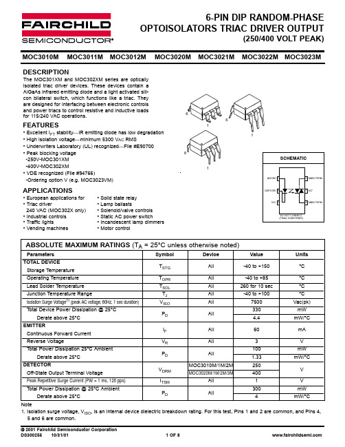
Fig. 4 LED Current Required to Trigger vs. LED Pulse Width
25
1.3
TRIGGER CURRENT - I FT (NORMALIZED)
TRIGGER CURRENT - I FT (NORMALIZED)
20
NORMALIZED TO: PWin ≥ 100 µs
2 OF 8
10/31/01 DS300255
6-PIN DIP RANDOM-PHASE OPTOISOLATORS TRIAC DRIVER OUTPUT
(250/400 VOLT PEAK)
MOC3010M
1.8
MOC3011M
MOC3012M
MOC3020M
100
6
4
10
2
1
0 25 30 40 50 60 70 80 90
Ambient Temperature - TA (oC)
0.1 -40 -20 0 20 40 60
o
80
100
TA, AMBIENT TEMPERATURE ( C)
DS300255
10/31/01
3 OF 8
Note 1. Isolation surge voltage, VISO, is an internal device dielectric breakdown rating. For this test, Pins 1 and 2 are common, and Pins 4, 5 and 6 are common.
Peak Blocking Current,Either Direction Rated VDRM, IF = 0 (note 1) Peak On-State Voltage,Either Direction ITM = 100 mA peak, IF = 0 Critical Rate of Rise of Off-State Voltage IF = 0 (figure 5, note2)
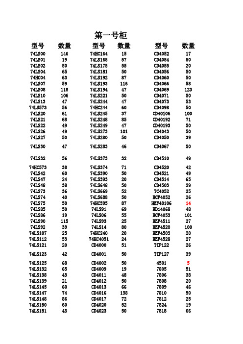
元器件清单
第一号柜型号数量型号数量型号数量74LS0014674HC16415CD405217 74LS011974LS16557CD405450 74LS025074LS17555CD405520 74LS046574LS18150CD405650 74HC046374LS19287CD406050 74LS075974LS193116CD406658 74LS0811874LS19447CD4069123 74LS1010674LS22150CD407150 74LS134774LS24447CD407353 74LS5735674HC24460CD409850 74LS206174LS24537CD40106100 74LS216874LS24885CD4019271 74LS224974LS24947CD4019350 74LS264974LS273101CD404350 74LS275074LS28050CD405039 74LS304774LS28346CD406750 74LS325674LS37332CD451049 74HC5733874LS37471CD452042 74LS426074LS39050CD452149 74LS472474LS39320CD451465 74LS483874LS64850CD450329 74LS733674LS66952TC405225 74LS744074LS68850HCF405226 74LS755074HC59587HEF4010614 74LS855074LS9169HD1406848 74LS861974LS0655HCF4053101 74LS9011574LS9325HEF451127 74LS923974LS1480HEF4520100 74LS1072574HC24020HEF450320 74LS1125374HC405124HEF452827 74LS12120CD400051TIP12226 74LS12342CD400150TIP12739 74LS12568CD40025045015 74LS13265CD400919780551 74LS13843CD401148780638 74LS13921CD401250780820 74LS14560CD401366780946 74LS14774CD4016138781050 74LS14886CD401772781225 74LS15060CD402052782419 74LS15143CD402350781866 74LS15373CD402448790572 74LS15464CD402648790647 74LS15550CD40275079084774LS16069CD40305079093874LS161103CD40404679124274LS163135CD40463079153574LS16437CD405144792419 LM31736LM33757第三号柜型号数量型号数量型号数量晶振(1M)6347P60左右电容683180左右455K1750P200左右1041500左右32.678K7556P160左右224150左右6M6162P150左右33480左右4M2675P120左右474220左右8M8682P180左右10520左右10M27电容101150左右272500左右11.0592M54105100左右9051(NPN)150左右12M53201150左右9011(NPN)80左右20M56221200左右9012(PNP)50左右14.318M6918180左右9013(NPN)100左右24M45271100左右9014(NPN)60左右40M90左右301150左右8550(PNP)100左右10.245M50左右331200左右9018(NPN)100左右80M18391100左右8050(NPN)120左右3.57954523471250左右发光二级管(红)110左右30M有源25501600左右发光二级管(绿)100左右36M有源38511180左右光敏二极管13电容(12P)67561100左右FR307二极管50左右15P50左右681200左右可调电容25-36P70左右3P100左右1021000左右发光二级管(黄)220左右4P100左右821250左右白发红光二极管200左右2.2P100左右122300左右红外发射208P100左右15270左右红外接收29 1P40左右202100左右发光二级管(白)20左右1.5P150左右222160左右发光二级管(双色)80左右5.6P/5.1P100左右302400左右IN60366P/6.8P100左右332180左右稳压二极管2.7V957P/8.2P80左右392100左右稳压二极管2.4V105 9P100左右472180左右IN4732101 10P200左右502120左右IN473049 18P250左右562150左右IN472842 20P180左右682250左右IN472998 22P800左右822150左右IN473395 27P180左右1031500左右IN4734125 30P700左右223200左右IN474429 33P1000左右333300左右IN47354239P750左右473350左右IN414876 IN40010IN4007270左右IN91458第五号柜型号数量型号数量型号数量MSP430F2TPS78001D2THS7001CPWP2 TLC0820AIN27THS4271D22TPS62100D22 AD60313INA137PA2DAC902E31 TLC082IP20DAC781114CX20106A20 OPA2822U40DAC782122MRR2045CTG40 INA213A20CE8301282DW23431 ADS1158202720120TPS6106220 UCC28600D20OPA355UA21117-3.346 TLV5636ID30TPS5416021117-1.830 VCA822ID30PGA113A62390nH100 INA333A82TPS601102470nH80 INA133UA20TPS612002X9312WP36 TLV2462A25TPS601002X9312TP30 ADS828E20ADS788222绕线电阻-36欧10 OPA691ID19ADS523720绕线电阻-30欧6 THS3001ID20VFC32KP22TPS6107020 TPS60310DGS2VCA81037激光二极管40 INA2134PA30INA28220激光接收管10 OPA2134PA35LP2950-33120聚焦透镜10 OPA234020TPS543020ADS111520TPS54331D20CSD17505Q5A15TPS6040020第七号柜型号数量型号数量型号数量AD83512BQ2402517MC337220 ADS834422AT25F51212MC159617 AD836919BUF301200MC164817 ADS850712CNY17-220FDS943120 ADS781820CSI5112PI0MPY6348 AD831020CXA1545AS14MUR15109 AD63716CXA1587S14NCP105020 AD99542CXA169129LM267620 AD71229ATHE8A3260LM290420 AD81130DAC855217LVC424572 AD83424DAC855524KMZ4125 ADS788619DAC900U15HS003819 AD832019DAC902E21LM388610AD84124DAC761116THS450335 AD83024DM9000AE9TL311622 AD84419EXB84115TLC22129 LF412CN35ispPAC805TLC37237 LF35750IR210330MLT0424 74HC57420IR211034MT888018 INA27130MC283328MOC306322 BTA41700B20MC336130MUR166030 BUF634722MC1450770IRF954040 INA12890MC14516323IRF54042 INA15919MC100LVEL6D20TIP32A0 INA233126MC908GP325TIP32C75 INA27034MC1202219IRF530N33 INA233224MAC97A680左右IRF9530N46 BUP30411MC336230IRF63031IRF64046第九号柜型号数量型号数量型号数量CBB102/100V100左右220uF/16V80左右V147-371015490.1uF/630V100左右220uF/250V10V147-391015416 0.47uF/630V100左右47uF/63V50左右二极管SA12A50 220uF/16V50左右47uF/100V100左右P6KE91120 103K/630V100左右100uF/16V120左右IN581752 CD100uF/25V120左右100uF/50V100左右IN582263 100uF/100V80左右330uF/16V80左右贴片9012100左右4.7uF/25V120左右470uF/16V50左右9013100左右4.7uF/50V110左右33uF/250V80左右8050150左右0.1uF/50V30左右47uF/16V100左右8550100左右0.1uF/160V120左右470uF/25V30左右磁环122.2uF/50V80左右1000uF/25V30左右贴片电阻1021500左右3.3uF/16V50左右1000uF/50V100左右贴片电阻0欧100左右4.7uF/250V50左右2200uF/16V60左右软键盘710uF/25V50左右4700uF/16V100左右太阳能控制板147uF/50V100左右2200uF/25V60左右贴片901880左右1uF/50V80左右C92-02恢复二极管30左右1000uF/100V20 100uF/50V30左右D92-02恢复二极管242200uF/100V2010uF/50V15左右变容二极管0-20P30470uF/50V1522uF/25V100左右变容二极管40-75P302200uF/50V2122uF/50V60左右变容二极管400-850P304700uF/50V2322uF/100V23二极管P6KE20020继电器943-1C-6DS2633uF/25V60左右P6KE120105继电器G5RL-1A-E1522uF/250V100左右P6KE15020220uF/450V20第二号柜型号数量型号数量型号数量电位器10126ADS77418OP2745电位器102177AD62029OP3744电位器103107AD770533TL08264电位器104161DAC083233TL08438电位器201150AD65024TL49475电位器202185AD66920TL384210电位器203218AD67719HA1732437电位器204194AD722820CA314058电位器501100AD985124N2567电位器502305AD985274N3551电位器503109MC1403496N13667电位器50448MC1444246N13750电位器253210MC148934P52137拨码开关4P28MC1406035MOC302053拨码开关8P52MC1451649PC81740电机驱动L29725MC1452673NEC2501121电机驱动L29826MC1443320高桥/10A20 BT15118MC14502723LF351116 BT113640MC348631LF35356 D827935NE555116LF35683 82C2920NE55647LF34725 TLP52150NE56461LF39854 D825321NE56769PT226235 D815540NE553292PT227216 80301NE553469ULN200324 80512MICRF002B5ULN280320 AT89C51103MC149622TLC154328 AT89S5117LM3552TLC254328 AT89S5212LM311144TLC551026 AT89C526LM32423TLS752820 AT89C205158LM336(5V)117TLE202219 HY626435LM336(2.5V)50TLV561625 HM6225639LM33928TEB403331 HM61166LM35850TDA282264 M27C12819LM38639TDA705010 GAL20V8B21LM39348HD727910 PIC16C57C6LF56759ST288A48 PIC12C508A16LM741101CH3412 24LC08B35LM187567ICL803840 74HC29524LM290430NB72329 ADC080930LM181217TL07250 ADC083267LM31926TLV246030 AD775123LM33148AD54524ISD256017AD53640ISD25902AD57030FR60722AD57420OP0755AD52618第四号柜型号数量型号数量型号数量C2073(功率管)16ST-ICL319一体化超声波传感器3 3DA87CJ48C181520QM-YT11 3DG800TA7267BP2310214 3DG130DJ107SP203910134 A94020晶闸管1A单硅1810432 KSP290750晶闸管1A双硅1547324 IRF84024EPM72181520442 TIP41C27EP1KTC144220237 TIP42C32EPC2LI20520366 KSP2222A80左右SHT11750240 TL431AC178XF-18D4250143 2DW2331USB转接器150433 2N540150左右热敏电阻75S10KBP31041 2N555140左右NTC10K(+/-)1%9KBPC80855 3D0175左右MYG7K33029KBPC21012 K112035ORD9216302W1013 3DV3330TA122DB106G41 2SC328020热敏电阻10K40左右E623203 DS18B2033C0412直流电机3470K15 BT33P0BPW410光敏电阻34B50K24 BT33FJ40杜邦-IP大量B100K10 DG20135小按键60左右2SK-24118 BBP1020拨码开关50左右K147120 B83472510-2P连接器40左右K51410 D88018人体感应模块163DU3388HM1温度模块149E70518温度传感器73DU310HS1101293DU320HTS11110AN5035C290120CS5125C197020CB35520BB639202SA130125BB11230TDA203023MQ-23ST251C123HY3011RE20015EL-1KL20LM3357SP-1KL0AD59026PT-23F13TCRT500015第六号柜型号数量型号数量型号数量C20790MAX43730MAX76430 C9450MAX50320MAX602920 JGX-5113F3MAX54223OPA12922 nRF24015MAX75632OPA13234 TL07113MAX76526OPA13430 ISD142020MAX80941OPA642u16 CSI511212MAX87431OPA335582SC3423-Y10MAX162620OPA300142SA1360-Y30MAX260120OPA36548 MAX03818MAX26212OPA56136 MAX19517MAX261120OPA60420 MAX20245MAX41065OPA63727 MAX23234MAX740120OPA69016 MAX29120MAX742119OPA222719 MAX323238磁壳绕线电阻器17OPA2270 MAX30620MAX29731OPA22822 MAX40018MAX30927OPA33322编码器2MCR100-630OPA54812 C0721763DG6C20OPA82034 2460C783DG8D20OPA84243射频线3DG182C193CG15C20 OPA656203DG7A20ADS114620第八号柜型号数量型号数量型号数量TL0459TRF37506MCR100-60 TL05230TSAC620022SC520020 TLC08379TLC7135732SC17909 TLC08546TDS2285102SC945100左右TPS7590122THS3091162SC19710 TLV246318安规电容0.1uF80左右应力传感器8 TLV154410安规电容1000pF40左右IN5401100左右SF56208UA73330直流电机30r/分7 MSP430F20027UCC2801926直流电机100r/分0 MSP430F22745UCC38C4322语音编程器2 MSP430F427010UGN35035语音操作WT588D-2010 PM30SSJ06010THS461315超声波发射36 RHRG301200409440超声波接受36SN65LBC184D10C9231282SA194318 SG352520SCA60C-N10000602霍尔开关FQZ-F-NK203 SP322029LM717115中周HGTF10-116 ST18820图像传感器T001P128中周HGTF10-213 ST27817智能控制器2交流接触器1 TPS73301474F15720电机驱动器BAL-352 TPS733335MQ-416电机驱动器DMD402A1 RF2317202SC190644固态继电器SSR-800 TPS3803202SC17910接近开关TK-SN5C3 ADE775517KS10A3 SMA射频插头磁珠29光电探测器10电源变压器19 1W高亮LED50第十号柜型号数量型号数量型号数量数码管LG3641BH38钽电容6.8uF40左右各种DIP座大量TOS-5101BH-B57钽电容22uF80左右LG3641AH23330uH90左右蜂鸣器50左右1uH150左右扬声器0 3.3uH100左右电源插头3210uH80左右9针串口头50左右33uH150左右9孔串口头23贴片68nH80左右电感120uH60左右贴片82nH80左右100uH100贴片0.22uH80左右220uH80左右贴片0.27uH80左右6.8uH/400V250左右 6.8mH110左右470uH120左右 4.7mH120左右680uH100左右10mH25左右12uH110左右100mH50左右15uH100左右色环1mH90左右47uH80左右立式电感1mH80左右56uH100左右立式电感33mH70左右3.3uF/150V50左右排针排座大量100uF/100V50左右IDC座大量10mH100左右连接器大量22uH65左右转接板大量钽电容10uF/25V40左右各种电阻大量钽电容22uF/16V5010000uF/63V20。
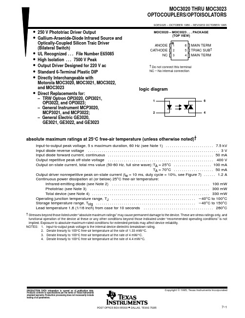
MOC3023中文资料
IMPORTANT NOTICETexas Instruments (TI) reserves the right to make changes to its products or to discontinue any semiconductor product or service without notice, and advises its customers to obtain the latest version of relevant information to verify, before placing orders, that the information being relied on is current.TI warrants performance of its semiconductor products and related software to the specifications applicable at the time of sale in accordance with TI’s standard warranty. Testing and other quality control techniques are utilized to the extent TI deems necessary to support this warranty. Specific testing of all parameters of each device is not necessarily performed, except those mandated by government requirements.Certain applications using semiconductor products may involve potential risks of death, personal injury, or severe property or environmental damage (“Critical Applications”).TI SEMICONDUCTOR PRODUCTS ARE NOT DESIGNED, INTENDED, AUTHORIZED, OR WARRANTED TO BE SUITABLE FOR USE IN LIFE-SUPPORT APPLICATIONS, DEVICES OR SYSTEMS OR OTHER CRITICAL APPLICATIONS.Inclusion of TI products in such applications is understood to be fully at the risk of the customer. Use of TI products in such applications requires the written approval of an appropriate TI officer. Questions concerning potential risk applications should be directed to TI through a local SC sales office.In order to minimize risks associated with the customer’s applications, adequate design and operating safeguards should be provided by the customer to minimize inherent or procedural hazards.TI assumes no liability for applications assistance, customer product design, software performance, or infringement of patents or services described herein. Nor does TI warrant or represent that any license, either express or implied, is granted under any patent right, copyright, mask work right, or other intellectual property right of TI covering or relating to any combination, machine, or process in which such semiconductor products or services might be or are used.Copyright © 1995, Texas Instruments Incorporated。
渗透压OSMOMAT 030使用说明
提示用户可能是无效结果
error
警告用户可能会损坏渗透压计或威胁本人身体健康
一般注意事项.
Notes, Safety Notices and Warnings | 3
Table of Contents
目录
标志,注意,警告 ................................................................................................................................................... 3
3.3
一般操作方式............................................................................................................... 17
4
OSMOMAT 030 冰点渗透压仪测量渗透压 ..........................................................................................19
4.3
校准液校准系统 ........................................................................................................... 22
4.4
测量样品溶液............................................................................................................... 24
moc3020规格书
moc3020规格书
以下是MOC3020规格书的内容:
1. MOC3020是一种高隔离压力的光耦合器,用于隔离输入和输出电路。
2. 输入部分包括一个红外LED和一个光电二极管。
输出部分包括一个三端可控硅。
3. MOC3020的最大隔离电压为7500Vrms,最大工作电流为60mA。
4. 输入端的最大正向电流为60mA,最大反向电压为6V。
5. 输出端的最大正向电流为0.1A,最大反向电压为400V。
6. MOC3020的触发电流为5mA,触发电压为1.5V。
7. MOC3020的工作温度范围为-40°C至+100°C。
8. MOC3020采用DIP-6封装,适用于插装式电路板。
以上是MOC3020规格书的一些基本内容,详细的规格和参数请参考相关文档或官方资料。
MOC3021中文资料_数据手册_参数

万联芯城专注电子元器件配单服务,只售 原装现货库存,万联芯城所售芯片IC,电阻电容,二三极管等 物料,原装质量有保障,价格有明显优势,已为全国多家企 业提供配套服务,客户只需提交BOM表,即可获得优势报价 ,整单采购有优惠,万联芯城现货库存销售能够满足多种客 户的物料需求,一站式报价为客户节省采购成本,点 击进入万联芯城。
MOC3021特点*输入和输出VISO之间的隔离电压:5000Vrms*6pin DIP光电耦合器,Triac驱动器输出*高重复峰值关断状态电压Vdrm:最 小400V*关断状态电压的高临界上升率(dv/dt:最小100V/微秒)*双列直插式封装:MOC3020、MOC3021、MOC3022、MOC3023*宽 引线间距组件:MOC3020M、MOC3021M、MOC3022M、MOC3023M*表面安装组件: MOC3020S、MOC3021S、MOC3022S、MOC3023S*胶带和卷轴包装:MOC3020S-TA1、MOC3021S-TA1、MOC3022S-TA1、MOC3023STA1*UL批准(编号E113898)*CSA批准(编号CA91533-1)*FIMKO批准(NO.209049)*NEMKO批准(编号P99102464)*DEMKO批准 (编号99-04182)*SEMKO批准(编号9943380/01-20)*VDE批准(编号094722)MOC3021功能*电机控制*固态继电器*用于触发大功率 晶闸管和TRIAC*家用设备绝对最大额定值(Ta=25°C)参数符号额定值单位正向电流if50mareverse voltageVR6V输入功率耗散 pd70mwoff状态输出端电压vdrm400V峰值重复浪涌电流(pw=1ms,120pps)vtsm1输出集电极功率耗散pc300mw总功率耗散t330mw*1隔 离电压VISO5000Vr
天电光电 EMC 3020 产品 A19 球泡灯参考设计说明书

天电光电EMC 3020产品A19球泡灯参考设计Lightning EMC 3020 LED A19 Bulb Reference Design目录Table of contents简介Introduction (1)灯具规格需求Define lighting requirements (2)设计目标Define design goals (2)整灯方案规划Estimate system efficiency (2)确定LED型号及数量Calculate the number of LED needed (2)散热方案设计Thermal requirements (3)驱动电源Driver (5)二次光学配件Secondary optics (5)样灯完成及测试结果Prototyping and test results (6)BOM表估算Bill of materials (8)结论Conclusion (9)简介本参考设计手册系统描述了如何应用天电光电EMC系列3020LED产品来制作9W球泡灯。
3020LED产品可以提供卓越的光电性能并大幅降低灯具系统成本。
所制作的球泡灯可广泛应用于各种室内应用,涵盖家居及商用照明应用等。
天电光电3020LED产品提供良好的大电流驱动性能,低热阻,单颗功率可以达到1.2W,是制作球泡灯的最佳LED光源之一。
同时,在台灯,吸顶灯及筒灯应用里也有非常大的优势。
IntroductionThis application note details the design of a 9W LED bulb lamp using TDEMC 3020 LED. The 3020 LED offers industry-leading performance and reduces system cost sharply. LED bulb lamps are widely used in various of indoor and outdoor applications, residential and commercial lighting applications, etc. TD EMC 3020 LED provides good performance for over-current drive, low thermal resistance, and can achieve 1.2W, which is the best candidate for use in a bulb lamp. Meanwhile, there is a great advantage in desk lamp, ceiling light and down light applications.设计目标本次设计需要达到以下参数目标:整灯方案规划本次参考设计主要通过较低的温度、较高的光学效率、较高的电源效率来达到设计目标。
太阳能板安装指南说明书

• Keeping within the maximum permitted loadMake sure the support structure adheres to maximum permissible load requirements as prescribed by local ordinances, particularly in regions of high snow accumulations and high wind velocities. Take notice to possible bowing of the modules under high loads. Avoid installing fasteners, cable ties, etc. between the module backside and support structure (i.e. on mounting rails) as any sharp edges can damage module.• Grounding of the module and frameThe company installing the PV module frame is also responsible for the professional grounding. If the building is already equipped with an exterior lightning protection system the PVinstallation must be integrated in thep rotection system against direct effects of lightning. Country specific standards must be adhered to.A grounding method authorized by UL is mandatory in the US and Canada.Example UL:The modules can be connected to the grounding holes using a layin lug and a screw with serrated washer, washer and nut.Drawings:Ground connection using a cable lug, a bolt, a serrated washer, a washer and a nut.1) Layin lug3) Serrated washer 5) Nut2) Bolt 4) WasherWe recommend using the components as listed below. Any UL approved PV grounding method and components are also acceptable in the US and Canada.Table: Recommended componentsItem DescriptionManufacturer/ ManufacturerDistributor Part NumberGrounding Lug LayIn Lug IlscoGBL4 Bolt#632, SS McMaster Carr 92314A148 Serrated washer M5, SSMcMaster Carr 91120A140 Washer ID 9/64’’, OD 3/8’’, SS McMaster Carr 92141A007Nut#632, SSMcMaster Carr91841A007• Fire safetyThe roof construction and installation may affect the fire safety of a building; improper installation may contribute to hazards in the event of fire. For roof application, the modules should be mounted over a fire resistant covering rated for the application. The module is “nonexplosionprotected equipment”. Hence it must not be installed in the proximity of highly flammable gases and vapors (e.g. filling stations, gas containers, paint spraying equipment). The module must not be installed near open flames or flammable materials.• Suitable environmental conditionsThe module is intended for use in temperate climatic conditions.The module must not be subjected to concentrated light. It must not be immersed in water or constantly exposed to water spray (e.g. from fountains). There is risk of corrosion with exposure to salt (it is recommended that modules are installed at least 500 m or 1700 ft from the sea) and sulfur (sulfur sources, volcanoes). The module may not be exposed to extremely corrosive chemicals (e.g. emissions from manufacturing plants).• Suitable installationMake sure the module meets the technical requirements of the system as a whole. Ensure that other system components do not exert damaging mechanical or electrical influences on the modules. When connected in series, modules must all have the same amperage. When connected in parallel, the modules must all have the same voltage. The modules must not be connected together to create a voltage higher than the permitted system voltage. Modules must not be fitted as overhead glazing or vertical glazing (façade). Ensure that the mounting system can also withstand the anticipated wind and snow loads. There are openings at the base of the module frame to allow water fromprecipitation to drain. Ensure that these openings are not blocked nor partially blocked by the module installation method.Carefully read through these installation instructions before installing, operating or servicing the photovoltaic (PV) system. Failure to follow these instructions may result in bodily injury or damage to property. Keep these instructions! Working on a PV system requires specialized knowledge and must therefore be carried out only by appropriately qualified and authorized personnel. Keep children away!Warning noticesDanger of death from electric shock!Solar modules generate electricity as soon as they are exposed to light. The voltage of a single module is less than 50VDC. When several modules are connected in series, the summed voltage can be dangerously high. When the modules are connected in parallel the currents are summed together. Although touch protection is provided in the form of the fully insulated plug contacts, the following points must be observed when handling the solar modules to avoid the risk of fire, arcing and fatal electric shock:• T he installation of higher voltage systems should be done by qualified, licensed professionals.• D o not insert electrically conducting parts into the plugs or sockets!• D o not wear metallic jewelry while performing mechanical or electrical Instal-lation.• D o not fit solar modules and wiring with wet plugs and sockets! Tools and working conditions must be dry.• E xercise extreme caution when carrying out work on wiring and use the appropriate safety equipment (insulated tools, insulated gloves, etc.)!• D o not use damaged modules! Do not dismantle modules! Do not remove any part or label fitted by the manufacturer! Do not treat the rear of the laminate with paint, adhesives or mark it using sharp objects!D anger of death from electric shock! The inverter can produce dangerous, high voltages, even when not connected:• E xercise extreme caution when working on wiring and the inverter.• A fter switching off the inverter, it is essential to wait for the time interval specified by the manufacturer before beginning any further work. This allows the high voltage components time to discharge.• B e sure carefully to follow the inverter manufacturer’s installation instruc-tions.D anger of death from arcing! Modules generate direct current (DC) when any amount of light shines on them. When breaking a connected string of modules (e.g. when disconnecting the DC line from the inverter under load), a lethally strong arc can occur:• N ever remove the solar generator from the inverter while it is still connected to the main grid!•E nsure that the cable connections are in perfect condition (no cracking, soiling or other contamination)!Unpacking the modules and storage• O bserve the warnings on the packaging!The utmost care is required when handling the modules. Take care when unpacking, transporting, and storing them. Leave modules in packaging until they are to be installed. Carry modules with both hands. Do not use the connection socket as a handle. Do not stand modules on hard or rough ground. Do not stand modules on their corners. Ensure modules do not bow. Do not place modules on top of each other. Do not subject to load, do not stand on them, do not drop. Do not mark or work on them with sharp objects. Keep all electrical contacts clean and dry. In order to keep a record of your system, we recommend that you make a note of the serial numbers. If it is necessary to store the modules temporarily, a dry, ventilated room should be used.General safety informationEnsure that the module is used for its intended purpose only. Pay attention to the local ordinances, building standards and accident prevention regulations during installation. The safety information for other system components must also be followed.InstallationWhen installing the modules, please pay attention to:• Safety during installationDo not carry out installation work when there are strong winds. Secure yourself and other workers to avoid falling. Secure work materials to prevent articles from falling. Create a work zone to avoid accidents with other people.Quick Guide for UsersSolarWorld® solar modulesLast revised: November 2008Drawing:Bowing of the module under high mechanical front loads.See: ; 53421SolarWorld AGKurtSchumacherStraße 121453113 Bonn GermanyTelefon: +49 228 55920 0Telefax: +49 228 55920 99*********************www.solarworld.de SolarWorld Ibérica, S.L.C/La Granja 15, Bloque B1°B 28108 Alcobendas, Madrid SpainTel.: +34 91 4905999Fax: +34 91 6574967*********************www.solarworld.esSolarWorld California Inc. 4650 Adohr Lane Camarillo, CA 93012USATel.: +1 800 947 6527Fax: +1 805 388 6395 service@solarworld www.solarworld SolarWorld Korea Ltd.8551, Dunsanri, Bongdongwup,Wanjugun, Jeollabukdo 565902, KoreaTel: +82 2 2112 1871Fax: +82 2 2112 1949service@solarworld www.solarworld• R efer to section 690-8 of the National Electric Code (NEC) for an additional multiplying factor of 125% (80% derating) which may be applicable • O ver-current protection shall be in accordance with the requirements of Article 240 of the NEC • C onductor recommendations: 8-14 AWG (1.5-10 mm 2) USE2 (nonconduit)/ THWN2 (conduit ), 90°C wet rated • C able conduits should be used in locations where the wiring is accessible to children or small animals • M odification or tampering of diodes by unqualified personnel is not permitted. Please consult a SolarWorld Service Center for additional information regarding diode replacement/repair.Maintenance and cleaningGiven a sufficient tilt (at least 15°), it is generally not necessary to clean the modules (rainfall will have a selfcleaning effect). In case of heavy soiling, we recommend cleaning the modules using plenty of water (from a hose) without any cleaning agents and using a gentle cleaning implement (a sponge). Dirt must never be scraped or rubbed away when dry, as this may cause microscratches.We recommend that the system be inspected at regular intervals to ensure:1. All mounting points are tight and secure and free of corrosion.2. All cable connections are secure, tight, clean and free of corrosion.3. Cables are not damaged in any way.4. The conductivity of module frame to earth ground.Disclaimer of liabilitySince compliance with this guide and the conditions and methods of installation, operation, use and maintenance of the modules are not checked or monitored by SolarWorld AG, SolarWorld AG accepts no liability for damage arising through improper use or incorrect installation, operation, use or maintenance.Furthermore, liability for infringements of patent law or of other third party rights arising from the use of the modules is excluded unless we are automatically liable by law.1) Stainless steel serrated lock nut 2) Stainless steel washer3) Stainless steel M8 (5/16 inch) Thead bolt12313mounting area mounting area1/4 module length1/4 module length 1/8 module length1/8 module lengthdo not mount on the short side• Optimum orientation and tiltTo obtain maximum yield from the system, we recommend that you determine the best direction and tilt angle for the modules. Conditions for generating electricity are considered ideal when the sun’s rays strike the module perpendicular to its surface. To avoid performance drops in series circuits, ensure that all modules have the same orientation and tilt.• Avoidance of shadingEven partial shading will cause a yield reduction. A module is “shade free“ when the entire surface is shade free all year round and, even on the most unfavorable days of the year, receives unobstructed sunlight.• Adequate ventilationVentilation of the module backside is necessary to avoid the buildup of heat that can reduce performance.MountingEach module must be securely fastened at a minimum of 4 points. The frame has been stress tested for mounting by the long sides. The module should not be secured by its short sides.PV modules can be mounted to the substructure by clamping on (Example A) at the front side or by screwing (Example B) at the back side.Example A: ClampingExample B: BoltingThe clamping area (Example A) of the washer must cover at least 135 mm 2 or 0.21 in 2. A torque wrench must be used for assembly. In the examples shown, the tightening torque (using stainless steel M8 or 5/16 inch bolts) must be 20 Nm or 11.8 ftlbf. Use the existing holes for securing the module; do not drill any additional holes (doing so would void the warranty). Use appropriate corrosionproof fastening materials.WiringThe module is provided from the factory with preconnectorized cables. Under no circumstances should the junction box be opened.For the wiring, pay attention to:• Correct wiring schemeIn order to decrease voltage caused by indirect lightning strikes, all connecting cables should be as short as possible. Check that the wiring is correct before commissioning the system. If the measured open circuit voltage differs from the specifications, then there is a wiring fault. Ensure that the polarity is correct.• Correct plug connectionsMake connections only in dry conditions. Ensure that connections are secure and tight.• Use of suitable materialsUse special solar cable and suitable connectors only. Ensure that they are in perfect electrical and mechanical condition. Use only single wire cables. Select a suitable conductor diameter to minimize voltage drop.• Cable protectionWe recommend securing the cables to the mounting system using UVresistant cable ties. Protect exposed cables from damage using suitable precautions (e.g. laying them in plastic pipes). Avoid direct exposure to sunlight.Underwriters Laboratories Information (U.S. and Canada)• T he solar module electrical characteristics are within +/-10% of the module label indicated values of Isc ,Voc,and Pmpp under Standard Test Conditions (irradiance of 100 mW/cm 2, AM 1.5 spectrum, and a cell temperature of 25°C/77°F)•U nder normal conditions, a photovoltaic module is likely to experience conditions that produce more current and/or voltage than reported at standard testconditions. Accordingly, the values of Isc and Voc marked on this module should be multiplied by a factor of 1.25 when determining component voltage ratings, conductor capacities, fuse sizes, and size of controls connected to the PV output.SolarWorld Asia Pacific Pte. Ltd. 72 Bendemeer Road #0701, Luzerne Singapore 339941SingaporeTel.: +65 6842 3886Fax: +65 6842 3887 *********************www.solarworld.sgSolarWorld Africa Pty. Ltd. 20th Floor1 Thibault Square Cape Town, 8001South AfricaTel.: +27 21 421 8001 Fax: +27 21 421 8002service@solarworldafrica.co.za www.solarworldafrica.co.zaSolarWorld is:。
常见贴片三极管型号对照表

我的文档
14s
BAS125-04
Sie
14s
BAS125-04W
Sie
14
BAT114-099R
Sie
14
DTA114EUA
Roh
14
DTA114EKA
Roh
14
MUN5314DW1
Mot
14
DTA114ECA
Roh
14A
MMBD1504A
Nat
15s
BAS125-05
Sie
15s
BAS125-05W
N
SC70
npn dtr R2 100k 50V 100mA
N
SC59
npn dtr R2 100k 50V 100mA
DO
SOT363
dual pnp dtr 10k+10k
0A 0A 0B 0C 0D 0E 0F 0G 0H 0J 0K 0L 0M
Code 1 1
1 (red) 10 10A 10V 10Y 11 11 11 p11 t11
Codes / Markings SMD codes
1st character/以第一个字符为基准
0
1
2
5
6
7
A
B
C
F
G
H
K
L
M
P
Q
R
U
V
W
Z
印字 0 5 p01 t01 1 10 11 2 2 2 2 p02 t02 3 3
器件 2SC3603 SSTPAD5 PDTA143ET PDTA143ET
npn/pnp dtr 10k R1 2N3960
2233-气腹机说明书

危险级别及其安全性的说明
标志 危险级别
严重警告! 不遵守此项将导致严重的身体伤害甚至死亡。 警告! 不遵守此项将导致轻微的身体伤害或者会损坏该器材。 重要事项! 不遵守此项将导致该器材或者周边仪器设备的损坏。 注意! 最恰当的使用方法和一些其他有用的信息的提示。
德国 RICHARD WOLF GmbH 75438 Knittlingen Pforzheimerstr. 32 电话: +49 70 43 35-0 传真: +49 70 43 35-300 MANUFACTURER info@ 比利时/荷兰 N.V. Endoscopie RICHARD WOLF Belgium S.A. Industriezone Drongen Landegemstraat 6 9031 Gent -Drongen 电话: +32 92 80 81 00 传真: +32 92 82 92 16 endoscopy@richard-wolf.be www.richard-wolf.be 阿拉伯联和酋长国市场部 RICHARD WOLF Middle East P.O. Box 500283 AL Thuraya Tower 1 9th Floor, Room 904, Dubai 电话: +9 71 43 68 19 26 传真: +9 71 43 68 61 12 middle.east@ 美国 RICHARD WOLF Medical Instruments Corp. 353 Corporate Woods Parkway Vernon Hills, Illinois 60061 电话: +1 84 79 13 11 13 传真: +1 84 79 13 14 88 sales&marketing@ 法国 RICHARD WOLF France S.A.R.L. Rue Daniel Berger Z.A.C. La Neuvillette 51100 Reims 电话: +33 3 26 87 02 89 传真: +33 3 26 87 60 33 endoscopes@richardwolf.fr 英国 RICHARD WOLF UK Ltd. Waterside Way Wimbledon SW 17 0HB 电话: + 44 20 89 44 74 47 传真: + 44 20 89 44 13 11 admin@ 奥地利 RICHARD WOLF Austria Ges.m.b.H. Wilhelminenstraße 93 a 1160 Wien 电话: +43 14 05 51 51 传真: +43 1405 51 51 45 info@richard-wolf.at www.richard-wolf.at
光耦简介及常见型号
光耦简介及常见型号常⽤光耦简介及常见型号光电耦合器(简称光耦)是开关电源电路中常⽤的器件。
光电耦合器分为两种:⼀种为⾮线性光耦,另⼀种为线性光耦。
常⽤的4N系列光耦属于⾮线性光耦常⽤的线性光耦是PC817A—C系列。
⾮线性光耦的电流传输特性曲线是⾮线性的,这类光耦适合于弄开关信号的传输,不适合于传输模拟量。
线性光耦的电流传输⼿特性曲线接进直线,并且⼩信号时性能较好,能以线性特性进⾏隔离控制。
开关电源中常⽤的光耦是线性光耦。
如果使⽤⾮线性光耦,有可能使振荡波形变坏,严重时出现寄⽣振荡,使数千赫的振荡频率被数⼗到数百赫的低频振荡依次为号调制。
由此产⽣的后果是对彩电,彩显,VCD,DCD等等,将在图像画⾯上产⽣⼲扰。
同时电源带负载能⼒下降。
在彩电,显⽰器等开关电源维修中如果光耦损坏,⼀定要⽤线性光耦代换。
常⽤的4脚线性光耦有PC817A----C。
PC111 TLP521等常⽤的六脚线性光耦有:TLP632 TLP532 PC614 PC714 PS2031等。
常⽤的4N25 4N26 4N35 4N36是不适合⽤于开关电源中的,因为这4种光耦均属于⾮线性光耦。
经查⼤量资料后,以下是⽬前市场上常见的⾼速光藕型号:100K bit/S:6N138、6N139、PS87031M bit/S:6N135、6N136、CNW135、CNW136、PS8601、PS8602、PS8701、PS9613、PS9713、CNW4502、HCPL-2503、HCPL-4502、HCPL-2530(双路)、HCPL-2531(双路)10M bit/S:6N137、PS9614、PS9714、PS9611、PS9715、HCPL-2601、HCPL-2611、HCPL-2630(双路)、HCPL-2631(双路)光耦合器的增益被称为晶体管输出器件的电流传输⽐(CTR),其定义是光电晶体管集电极电流与LED正向电流的⽐率(ICE/IF)。
KODAK VISION3 250D色彩负片5207 7207产品说明说明书
KODAK VISION3 250DCOLOR NEGATIVE FILM 5207 / 7207TECHNICAL DATA / COLOR NEGATIVE FILM MARCH 2022H-1-5207 KODAK VISION3 250D Color Negative Film 5207/7207 is amedium-speed daylight-balanced emulsion.VISION3 250D Film has outstanding skin tones and colorreproduction, while adding technical innovations thatimprove product performance and increase productversatility. The proprietary, advanced Dye LayeringTechnology (DLT) provides noticeably reduced grain inshadows, allowing you to pull out an amazing amount ofshadow detail. The proprietary Sub-Micron Technologyenables 2 stops of extended highlight latitude, so you canfollow the action into bright light-in a single shot-withoutworrying about blown-out details.VISION3 250D Film is designed to extend the capabilities ofthe DI (digital intermediate) process. The improved grainprovides better to signal to noise capabilities allowing thecolorist to provide greater detail in shadows, while theextended highlight latitude enables improved digital"dodging and burning" to provide more details in highlights.BaseKODAK VISION3 250D Color Negative Films 5207 and 7207have an acetate safety base with rem-jet backing.StorageStore unexposed film at 13 C (55 F) or lower. For extendedstorage, store at -18 C (0 F) or lower. Process exposed filmpromptly.Store processed film according to the recommendations inISO 18911:2010, Imaging Materials - Processed SafetyPhotographic Films - Storage Practices.Short Term (less than 6 months)Long Term (more than 6 months)Unexposed film in original, sealedpackage13 C (55 F)RH below 60%-18 C(0 F)RH below 50%Exposed film, unprocessed-18 C(0 F)RH below 20%Not recommended.Process filmpromptly.Process film21 C (70 F)RH 20 to 50%2 C (36 F)RH 20 to 30%This relates to optimized film handling rather than preservation; static, dust-attraction and curl-related problems are generally minimized at the higher relative humidity. After usage, the film should be returned to the appropriate medium- or long-term storage conditions as soon as possible. Warm-up TimesTo prevent film telescoping, moisture condensation, and spotting, allow your film to warm to room temperature (21C/70F) before use:Film PackageRecommended Warm-up Time (Hours)8 C (15 F) Rise 39 C (70 F) Rise16 mm 1 1 ½35 mm 3 5For more information about film storage and handling, see ANSI/PIMA ISO-18911, SMPTE RP131-2002, andKODAK Publication No. H-845, The Essential Reference Guide for Filmmakers, available online at/go/referenceguide.Darkroom RecommendationsDo not use a safelight. Handle unprocessed film in total darkness.ExposureExposure IndexesDaylight (5500K): 250Tungsten (3200K): 64 (with 80A filter)Use these indexes with incident or reflected light exposure meters and cameras marked for ISO or ASA speeds or exposure indexes. These indexes apply for meter readings of average subjects made from the camera position or for readings made from a gray card of 18 percent reflectance held close to and in front of the subject. For unusually light or dark colored subjects, decrease or increase the exposure i ndicated by the meter accordingly.Color BalanceThese films are balanced for exposure with daylight illumination (5500K). For other light sources, use the correction filters in the table that follows.Daylight (5500 K)None250 Metal Halide None250H.M.I.None250 KINO FLO 55None250 Tungsten (3000 K)WRATTEN 2 OpticalFilter / 80A64Tungsten (3200 K)WRATTEN 2 OpticalFilter / 80A 64KINO FLO 29 KINO FLO 32WRATTEN 2 OpticalFilter / 80A64Fluorescent, WarmWhite †Color CompensatingCC20M + CC05R125Fluorescent, CoolWhite †Color CompensatingCC40B100* These are approximate corrections only. Make final corrections during printing.† These are starting-point recommendations for trial exposures. If the kind of lamp is unknown, a KODAK Color Compensating Filter CC20M + CC10B can be used with an exposure index (EI) of 125.Note: Consult the manufacturer of high-intensity ultraviolet lamps for safety information on ultraviolet radiation and ozone generation.Exposure Table-Daylight IlluminationAt 24 frames per second (fps), 180-degree shutter opening, use this table for average subjects that contain a combination of light, medium, and dark colors:Lens Aperture f/1.4f/2f/2.8f/4f/5.6f/8f/11f/16FootcandlesRequired1020 40801603206401250Reciprocity CharacteristicsYou do not need to make any filter corrections or exposure adjustments for exposure times from 1/1000 of a secondto 1 second.ProcessingProcess in Process ECN-2.Most commercial motion-picture laboratories provide a processing service for these films. See KODAK Publication No. H-24.07, Processing KODAK Color Negative Motion Picture Films, Module 7 available online at/go/h24, for more information on the solution formulas and the procedure for machine processing these films. There are also pre-packaged kits available for preparing the processing solutions. For more information on the KODAK ECN-2 Kit Chemicals, check Using KODAK Kit Chemicals in Motion Picture Film Laboratories KODAK Publication No. H-333, availableonline at /go/h333.IdentificationAfter processing, the product code numbers 5207, or 7207 emulsion, roll, and strip number identification, KEYKODE Numbers, and manufacturer/film identification code (EN) are visible along the length of the film.Post-ProductionScanningThe wider exposure latitude in KODAK VISION3 Films differentiate film capture from the limited dynamic range of digital capture. Digital "dodging and burning," a very powerful tool in the colorists' toolkit, is now even more powerful—up to two stops more image information canbe extracted from scene highlights in VISION3 Films.If traditional 10-bit scanner data encoding schemes are used to digitize films having this extended density range, highlight information captured on these films could be lost. Kodak has recommendations for extracting the full density range stored on highdynamic range films in a technical document titled Scanning Recommendations for Extended Dynamic Range Camera Films, available online at/go/scanning.Laboratory Aim Densities (LAD)To maintain optimum quality and consistency in the final prints, the laboratory must carefully control the color timing, printing, and duplicating procedures. To aid in color t iming and curve placement, negative originals should be t imed relative to Laboratory Aim Density (LAD) Control Film. The LAD Control Film provides both objective sensitometric control a nd subjective verification of the duplicating procedures used by the laboratory.In the LAD Control Method, the electronic color analyzer used for color timing is set-up with the LAD Control Film to produce a gray video display of the LAD patch, corresponding to 1.0 neutral density (gray) on the print. The negative printing original is then scene-to-scene timed. There are specific LAD values for each type of print or duplicating film that the original can be printed on. For print films, the LAD patch is printed to a neutral gray of 1.0 visual density. For duplicating films, the specified aims are at the center of the usable straight-line portion of the sensitometric curve of the film.Due to normal variations in exposure and processing of color negative films, particular scenes may not print exactly at the same printer lights as the LAD Control Film. The LAD Control Film is intended as a set-up tool for electronic color analyzers and printers. It is NOT a reference that every scene must match. Normal film-to-film and scene-to-scene exposure variability is accommodated by the color timing (grading) process, on an electronic color analyzer set up with the LAD Control Film. Normally exposed and processed color negatives will typically print well within the range of an additive printer setup with the LAD Control Film, although SIGNIFICANT or UNEXPECTED departures from this center point balance may indicate an exposure/filtration problem with the cinematography or with the process control. Some specialized films and/or specialized negative processing techniques (push-processing, pull-processing, "skip-bleach" processing, etc.) may require more extreme adjustment from the LAD printing condition to attain desired results.More information is contained in KODAK Publication H-61,Image StructureFor more information on image-structure characteristics, see KODAK Publication No. H-845, The Essential Reference Guide for Filmmakers available online at /go/referenceguide .Modulation Transfer FunctionThe "perceived" sharpness of any film depends on various components of the motion picture production system. The camera and projector lenses and film printers, among other factors, all play a role. But the specific sharpness of a film can be measured and is charted in the Modulation Transfer Function Curve.This graph shows a measure of the visual sharpness of this film. The x-axis, “Spatial Frequency,” refers to the number of sine waves per millimeter that can be resolved. The y-axis, “Response,”corresponds to film sharpness. The longer and flatter the line, the more sine waves per millimeter that can be resolved with a high degree of sharpness — and the sharper the film.rms GranularityThe “perception” of the graininess of any film is highly dependent on scene content, complexity, color, and density. Other factors, such as film age, processing,exposure conditions, and telecine transfer may also have significant effects.Read with a microdensitometer, using a 48-micrometre aperture. To find the rms Granularity value for a given density, find the density on the left vertical scale and follow horizontally to the characteristic curve and then go vertically (up or down) to the granularity curve. At that point, follow horizontally to theGranularity Sigma D scale on the right. Read the number and multiply by 1000 for the rms value.Note: This curve represents granularity based on modified measuringtechniques. Sensitometric and Diffuse RMS Granularity curves are produced on different equipment. A slight variation in curve shape may be noticed.SensitometryThe curves describe this film's response to red, green, and blue light. Sensitometric curves determine the change in density on the film for a given change in log exposure.Spectral SensitivityThese curves depict the sensitivity of this film to the spectrum of light. They are useful for determining,modifying, and optimizing exposure for blue- and green-screen special-effects work.Spectral Dye-Density CurvesThese curves depict the spectral absorption of the dyesformed when the film is processed. They are useful for adjusting or optimizing any device that scans or prints the film.Note: Cyan, Magenta, and Yellow Dye Curves are peak-normalized.Note: The sensitometric curves and data in this publication represent product tested under the conditions of exposure and processing specified. They are representative of production coatings, and therefore do not apply directly to a particular box or roll of photographic material. They do not represent standards or specifications that must be met by Eastman Kodak Company. The company reserves the right to change and improve product characteristics at any time.Available Roll Lengths and FormatsSee Kodak Motion Picture Products Catalog at /go/mpcatalog To order film in the United States and Canada, call 1- 800-356-3259, prompt 3.Worldwide customers can find the nearest sales office at /go/salesofficesKODAK VISION3 250D Color Negative Film 5207 / 7207KODAK Publication No. H-1-5207 Kodak, Keykode, Vision, and Wratten and the Kodak logo are trademarks.Revised 3-22© 2022 EASTMAN KODAK COMPANY。
MOC3020X中文资料
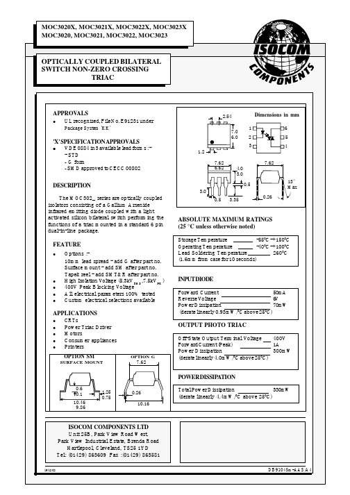
0.5
3.35
ABSOLUTE MAXIMUM RATINGS (25 °C unless otherwise noted) Storage Temperature -550C - +1500C Operating Temperature -400C - +1000C Lead Soldering Temperature 2600C (1.6mm from case for 10 seconds) INPUT DIODE Forward Current 50mA Reverse Voltage 6V Power Dissipation 70mW (derate linearly 0.93mW/0C above 250C) OUTPUT PHOTO TRIAC Off-State Output Terminal Voltage 400V Forward Current (Peak) 1A Power Dissipation 300mW (derate linearly 4.0mW/0C above 250C) POWER DISSIPATION
Output
Coupled
Input Current to Trigger ( IFT )(note 2 ) MOC3020 MOC3021 MOC3022 MOC3023
30 15 10 5
mA mA mA mA
µA
VD = 3V ( note 2 )
Holding Current , either direction ( IH ) Input to Output Isolation Voltage VISO 5300 7500
100
VRMS VPK
See note 3 See note 3
MOC3021

特性:
400V光敏可控硅驱动器输出 砷化镓二极管红外源和光学耦合硅Traic驱动器(双向开关) UL认证:档案编号E65085 高隔离:7500V峰值 输出驱动器设计为220VAC 标准6端子塑料DIP 可直接与摩托罗拉MOC3020,MOC3021,MOC3022和MOC3023互换 绝对最大额定值在25 C
机械信息:
每个器件包括一个砷化镓红外发光二极管光耦合到一个硅光敏在6端 子导致在一个不导电塑料复合封装的框架上。可以承受的情况下不变形 和设备的性能特点保持稳定时,在高湿度条件下操作的焊接温度。
MOC3201
注:a.信息在0,13(0.005)的真实位置,最大的物质条件和安装单 位(TP)半径。 B.引脚1标识指数点。 C的尺寸内给予JEDECMO-001 AM尺寸下降。 D.所有线性尺寸以毫米和parenthetically英寸给出。
应用:
螺线管/阀门控制 灯镇流器 外设115/240接口微处理器吸尘器 电机控制
白炽灯调光器
图信息:
图1.临界上升率测试电路
MOC3201
EMITTING二极管触发电流(归)与开放式空气温度图2:
MOC3201
MOC3201
图5阻性负载
MOC3201
图6感性负载敏感栅可控硅
图7感性负载非敏感栅可控硅
moc3023引脚参数

MOC3023引脚参数导言M O C3023是一种隔离型三端输出光耦合器,它在电子设备中广泛应用。
本文将介绍M OC3023的引脚参数及其作用,帮助读者更好地理解和应用这款器件。
引脚说明M O C3023的引脚共有6个,分别为:1.`1`脚:主光电耦合器的阳极(A1)。
2.`2`脚:主光电耦合器的阴极(A2)。
3.`3`脚:辅助开关阴极(G2)。
4.`4`脚:辅助开关阳极(A2)。
5.`5`脚:未连接引脚(N C)。
6.`6`脚:未连接引脚(N C)。
引脚功能分析1.主光电耦合器引脚主光电耦合器引脚(`1`脚和`2`脚)用于输入控制信号,实现光耦合器的隔离功能。
其中,`1`脚为阳极,`2`脚为阴极。
主光电耦合器引脚的主要特点有:-高隔离电压:主光电耦合器引脚间的隔离电压可达数千伏,保证了输入信号的安全与可靠。
-低驱动电流:主光电耦合器引脚的驱动电流较低,能够节省能量,并减少热量的产生。
2.辅助开关引脚辅助开关引脚(`3`脚和`4`脚)可用于控制外部开关电路。
其中,`3`脚为辅助开关阴极,`4`脚为辅助开关阳极。
辅助开关引脚的主要特点有:-高耐压能力:辅助开关引脚能够承受较高的电压,在外部开关电路中起到可靠的控制作用。
-小型化设计:辅助开关引脚采用小型化设计,适用于紧凑的电路布局环境。
3.未连接引脚M O C3023的剩余两个引脚(`5`脚和`6`脚)为未连接引脚,在使用中不需要接触到其他电路。
未连接引脚的设计原因是为了保证产品的兼容性和应用灵活性,使得M O C3023能够适应多种不同的电路布局和连接方式。
总结M O C3023是一款常用的光耦合器,它具有较高的隔离电压、低驱动电流和高耐压能力等特点。
通过本文所介绍的引脚参数,我们可以更好地理解和应用这款器件。
(完)。
BELIMO 消火和烟雾培训手册说明书

Basic Fire and Smoke Actuators & DampersContents• Basic damper and actuator concepts • Types of Systems• Control• Standards and Codes• Indicator Lights and Aux Switches • Product & New Applications• SpecificationsBasic damper and actuator conceptsUL555 (fire dampers)Courtesy of PottorffCourtesy of PottorffAt 165°F (typically) a fusible link melts and the blades drop down or arepulled down by a spring (horizontal or dynamic airflow).JackshaftDamper SleeveActuatorUL555S (smoke dampers)Courtesy of PottorffBlade & SealStand-offbearing Damper FrameAxleDrive ArmFrameCourtesy of PottorffSmoke Damper – no temperature limit. Controlled by smoke detectors or indirectly via smoke control panel.Combination Fire &SmokeManual Reset HighTemperature Limit165F210F250F350F Courtesy of PottorffActuators are tested as an assembly with the damper.Not listed alone.UL555(S) requires 75 second time.Test covers leakage, high velocity closing, other functions.Types of SystemsTwo types of damper use –1.Containment / Compartmentation90% simply close to prevent smoke or fire spread.2. Engineered smoke controlApplied in zone pressurization, stairwells, elevator shafts, lobby pressurization, atria and large spaces.Can be exhaust or pressurization to prevent smokespread.CompartmentationEngineered Smoke Control Systems Organized control of smoke movement rather than containment is required as indicted in lessons learned from past fires.The total situation is considered.Engineered Smoke Control Systems Stairwell pressurizationAtria smoke extractionElevator shaft pressurizationVentilated lobbiesCorridor dampersCeiling dampersShaft dampersDuct dampersFire & Smoke doorsSmoke Extraction Shafts and Fans Sandwich or building pressurization systemsConsultants will develop a rational analysis smoke control strategy1.Sequence of operation2.Detail the response to alarms. Manual stations willstart purge or pressurization sequences instairwells. Floor by floor sequence to containsmoke.3.Positive Feedback and what the system should doif feedback is not received in the specified time.Dedicated: no other function but smoke control. Non-dedicated may be a HVAC air handling unit.RELIEF FAN SYSTEMOA RFRFDEach actuator gets separate output from smoke control panel.Reopenable dampers can assist inexhausting dangerous amounts of toxic, low temperature smoke from the firezone and to pressurize adjacent zones to prevent spread.Courtesy of HPAC EngineeringControlSmoke Control can be managed by BAS or the Fire Alarm System Some trend to shift to an integrated system - Fire protection and BAS combined.UL864 required for Fire Alarms, not actuators or dampers.ControlCourtesy of HPAC EngineeringBAS or the Fire Alarm System can provide:1.Hardware for operation2.Firefighter Smoke Control Station3.Process logic to control devices4.Monitoring5.Initiation of automatic smoke control can comefrom smoke detectors, alarms, water flowswitches in sprinkler pipes, or pull stations into the fire system.Fire Fighters Smoke Control System:The Front End of every smokecontrol system is the Fire FightersControl Station:LED’s associated with every fan &damperManual overrides for every fan &DamperFans & dampers are typically tied toBASInformation from dampers & fans istaken and processed by either theFire or BAS system to control thecorrect fans & dampers at the righttime.SMOKE CONTROLControl Panel Combination Fire &LOCAL SMOKE CONTROLCourtesy of PottorffPowerActuatorActuatorsWill need parallel wiring fortwo large section dampers.Smoke detector,high temp limit,contact on firealarm controlpanel orsystem.80% of dampers use this configuration.Single sensor, manual reset.HEAT, SMOKEReopenable DamperDETECTOR, OROTHER RELAYFROM ALARMSYSTEMAUTO:IF DUCT TEMPERATURE REACHES 165F OREXTERNAL ALARM CONTACT OPENS, POWERIS CUT TO ACTUATOR AND DAMPERSPRINGS CLOSED. MANUAL RESET.High Limit Sensor and Reset switch Status Lights (Optional)Standards & CodesCodes and StandardsVertical Shafts – fire-smoke dampers required at penetrations This is one of the the most important protectionagainst smoke spread in a fire.Elevator shafts and lobbies – sprinkler trade-offs exist in IBC, not UBC.Corridors – derated requirement in IBC, not UBC.These are the escape paths. They should be protected. Youare not safer in an IBC building.Pressurized stairway – required in IBC and UBC.People must be able to escape fires.UL555 & UL555S•Damper manufacturer requirement•High temperature test for 250F or 350F•Damper and Actuator•Heated Air Flow test ensures actuator closes damper. •Others for damper only: Drop test, salt spray, Leakage rating •75 second is the UL 15 time requirement. UBC required 15seconds for some years.Belimo is 15 seconds for FSLF and FSNF; 75 sec drive and 20 sec spring for FSAF.NFPA•90A, B HVAC•92 Smoke Control Systems for atria and large spaces.•80 (fire) & 105 (smoke) doors and dampers•TESTING REQUIREMENTSEvery 4 years per NFPA. Local codes vary.Hospitals every 6 years.NFPA•NFPA 80 is fire opening protectives – fire doors and dampers•NFPA 105 is smoke opening protectives – smoke doors and dampers.•Testing requirements:•At end of first year•Every 4 years•Except hospitals – every 6 years.Life Safety Standards and Codes are always changing and developing.Trade-offs between levels of cost and safety will always exist. Different views exist.Purpose of Life Safety is to protect people, not buildings.By protecting the building we protect people. First code to clearly state this was the 1997 UBC.Codes and Standards are quite intensive asubject. Not covered here in any detail.•Codes require life safety systems be maintained in operating condition.•Rules are mostly unwritten.•Use common sense – if it breaks, fix it.•AHJ – usually the Fire Marshal or Building Official – is the final authority on dampers and alarms.Actuator & DamperReplacement and RepairActuator & Damper Replacement and Repair•NFPA 80 & 105 require maintenance and repair or replacement.•UL accepts actuator replacement; does not regulate. •Use Belimo or damper manufacturer instructions. •Actuator should be UL555S Listed with the manufacturer. •“Equal or Better” is required.•Separate Belimo documents detail repairs on different types of dampers.Balanced Strategy SprinklersStructural Compartmentalization AlarmsFire and Smoke Dampers Smoke Control Systems MaintenanceIndicator Lights and Aux SwitchesIndicator LightsCourtesy of PottorffRed Green AmberProduct & New ApplicationsBelimo F&S Product Line FSLF 4 sq.ft.FSNF 12 sq.ft.FSAF*A max 18 sq.ft.2-position 24, 120, 230 volt.24 VDC as well as ACFSAFB24-SR 2-10Vdc ProportionalUnderfloor HVAC Pressure Control FSAFB24-SRStairwell PressurizationStairwell pressurization allows occupants to safely exit the building, while firefighters can stage and safely access an upper level fire.Typically onedamper and pressure sensor per 3 floors.Stairwell PressurizationDamperProportional 2-10Vdc F&S ActuatorFSAF24-SRWhy Specify1. 5 year warranty2.Micro Controller: Actuator cannot burn out if stalled before full rotation is achieved.3.Motor runs cool for a long life span.4.DC Motor: No noise when holding.5.Very low Current Draw6.Steel cold-weld clamp: no shaft slip7.Steel housing: rugged integrity8.ISO 9001 Quality ControlBelimo Quality。
- 1、下载文档前请自行甄别文档内容的完整性,平台不提供额外的编辑、内容补充、找答案等附加服务。
- 2、"仅部分预览"的文档,不可在线预览部分如存在完整性等问题,可反馈申请退款(可完整预览的文档不适用该条件!)。
- 3、如文档侵犯您的权益,请联系客服反馈,我们会尽快为您处理(人工客服工作时间:9:00-18:30)。
IMPORTANT NOTICE
Texas Instruments and its subsidiaries (TI) reserve the right to make changes to their products or to discontinue any product or service without notice, and advise customers to obtain the latest version of relevant information to verify, before placing orders, that information being relied on is current and complete. All products are sold subject to the terms and conditions of sale supplied at the time of order acknowledgement, including those pertaining to warranty, patent infringement, and limitation of liability.
TI warrants performance of its semiconductor products to the specifications applicable at the time of sale in accordance with TI’s standard warranty. Testing and other quality control techniques are utilized to the extent TI deems necessary to support this warranty. Specific testing of all parameters of each device is not necessarily performed, except those mandated by government requirements.
CERTAIN APPLICATIONS USING SEMICONDUCTOR PRODUCTS MAY INVOLVE POTENTIAL RISKS OF DEATH, PERSONAL INJURY, OR SEVERE PROPERTY OR ENVIRONMENTAL DAMAGE (“CRITICAL APPLICATIONS”). TI SEMICONDUCTOR PRODUCTS ARE NOT DESIGNED, AUTHORIZED, OR WARRANTED TO BE SUITABLE FOR USE IN LIFE-SUPPORT DEVICES OR SYSTEMS OR OTHER CRITICAL APPLICATIONS. INCLUSION OF TI PRODUCTS IN SUCH APPLICATIONS IS UNDERSTOOD TO BE FULLY AT THE CUSTOMER’S RISK.
In order to minimize risks associated with the customer’s applications, adequate design and operating safeguards must be provided by the customer to minimize inherent or procedural hazards.
TI assumes no liability for applications assistance or customer product design. TI does not warrant or represent that any license, either express or implied, is granted under any patent right, copyright, mask work right, or other intellectual property right of TI covering or relating to any combination, machine, or process in which such semiconductor products or services might be or are used. TI’s publication of information regarding any third party’s products or services does not constitute TI’s approval, warranty or endorsement thereof.
Copyright © 1998, Texas Instruments Incorporated
ÍøÕ¾ÊÇÒ»¸öÃæÏò¹ã´óµç×Ó°®ºÃÕßÖÐСÐÍÆóÒµ¹¤³Ì¼¼ÊõÈËÔ±µÄµç×Ó¼¼ÊõÓ¦ÓÃÖ÷ÒªÄÚÈÝÓÐÆ÷¼þ×ÊÁϵç×Ó¼¼ÊõÖ§³Ö·þÎñתÈúÍÒý½øµÈÐÅÏ¢
°æȨÊôÔ-×÷Õß
在使用本资料或软件时欢迎到网站内的BBS
中发表
技术论坛
欢迎到网站下载
电子爱好者http://www.etuni.com。
