PM3FMS中文资料
日本三和PM3笔记本式万用表中文说明书
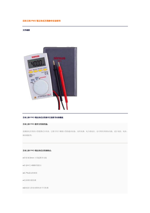
文件截图
日本三和PM3笔记本式万用表中文说明书内容概述
日本三和PM3数字万用表用途:
是测量电压用的小型便携式万用表。它既可用于测量小型的通讯设备、家用电器、电力线电压,也可利用其附加功能,进行电阻、电容、频率测量等。
日本三和PM3笔记本式万用表特点:
●厚度8.5mm小型超薄多功能
●背光及控制带LED的蜂鸣器
日本三和PM3笔记本式万用表特性:
●显示:数值4000
●抽样率:数值3次/秒
●安全规格:IEC1010 CAT. II DC/AC500V MAX.
日本三和PM3笔记本式万用表技术参数
PM3
测量量程
最高准确度
分辨率
输入电阻
直流电压
400m/4/40/400/500V
±(0.7%+3)
±(0.7%+5)
0.1Ω
占空比
0.1-99%
通断
10Ω-120Ω以下有蜂鸣音开路电压:约0.4V
二极管测试
开路电压约1.5V
频率特征
40-400HZ
内置电池
纽扣式锂电池C8*W56*D11.5mm/约85g
附件
手册型护套(C-PM3),使用说明书
0.1mv
DCV
10M-100MΩ
ACV
10M-11MΩ
交流电压
4/40/400/500V
±(2.3%+10)
0.001v
电阻
400/4K/40K/400K/4M/40MΩ
±(2.0%+5)
0.1Ω
电容器容量
4n/40n/400n/4μ/40μ/200μF
±(5.0%+10)
PM-3 用户手册说明书

PM-3 Planar Magnetic HeadphonesUser ManualContentsImportant Safety Information ‐‐‐‐‐‐‐‐‐‐‐‐‐‐‐‐‐‐‐‐‐‐‐‐‐‐‐‐‐‐‐‐‐‐‐‐‐‐‐‐‐‐‐‐‐‐‐‐‐‐‐‐‐ 2 Introduction ‐‐‐‐‐‐‐‐‐‐‐‐‐‐‐‐‐‐‐‐‐‐‐‐‐‐‐‐‐‐‐‐‐‐‐‐‐‐‐‐‐‐‐‐‐‐‐‐‐‐‐‐‐‐‐‐‐‐‐‐‐‐‐‐‐‐‐‐‐‐‐‐‐‐‐‐ 3 Feature Highlights ‐‐‐‐‐‐‐‐‐‐‐‐‐‐‐‐‐‐‐‐‐‐‐‐‐‐‐‐‐‐‐‐‐‐‐‐‐‐‐‐‐‐‐‐‐‐‐‐‐‐‐‐‐‐‐‐‐‐‐‐‐‐‐‐‐‐‐‐ 4 Using Your Headphones ‐‐‐‐‐‐‐‐‐‐‐‐‐‐‐‐‐‐‐‐‐‐‐‐‐‐‐‐‐‐‐‐‐‐‐‐‐‐‐‐‐‐‐‐‐‐‐‐‐‐‐‐‐‐‐‐‐‐‐‐‐ 5 Specifications ‐‐‐‐‐‐‐‐‐‐‐‐‐‐‐‐‐‐‐‐‐‐‐‐‐‐‐‐‐‐‐‐‐‐‐‐‐‐‐‐‐‐‐‐‐‐‐‐‐‐‐‐‐‐‐‐‐‐‐‐‐‐‐‐‐‐‐‐‐‐‐‐‐‐‐ 7Important Safety InformationBefore using your headphones, make sure to lower the volume level on your headphone amplifier or portable device. Prolonged exposure to high volumes may result in temporary or even permanent hearing loss.Be aware of your surroundings. Using headphones may diminish your ability to hear important ambient sounds. Exercise caution particularly at railroad tracks, crosswalks, or any environment where motor vehicles or bicycles are present.It is always recommended to lower the volume level prior to connecting or disconnecting your headphones.Do not leave your headphones or cables in an area where people or pets might trip over them.Always supervise children who are using these headphones.IntroductionCongratulations! You are now the proud owner of a pair of truly portable closed‐back planar magnetic headphones.The OPPO PM‐3 utilizes a planar magnetic driver that is developed from the driver in our EISA award‐winning PM‐1 headphones. Technological breakthroughs achieved during the PM‐1’s development, such as the 7‐layer double‐side voice coil diaphragm design and FEM‐optimized neodymium magnet system, have enabled OPPO to reduce the weight of the planar magnetic drivers while maintaining excellent sound quality and high sensitivity. The PM‐3 driver’s smaller size and high sensitivity make it especially suitable for portable use, and this driver would not have been possible without the breakthroughs achieved in the PM‐1’s driver design.In the PM‐3’s planar magnetic driver, sound is generated by a very thin and light diaphragm which is driven in a symmetric pull‐push manner, and the magnetic system and conductor patterns have been optimized for maximum sensitivity and consistency. This allows the diaphragm to generate very stable and linear piston‐like vibrations, ensuring phase coherence and high resolution performance with minimal distortion. Featuring a light weight closed back design and easily driven with any smartphone or portable music player, the PM‐3 headphones will enable you to enjoy your favorite music anywhere while being isolated from outside noise.We are proud of the work we have put into these headphones, and we hope they bring you years of enjoyment.Feature Highlights∙Unique planar magnetic driver with FEM‐optimized neodymium magnet system∙7‐layer double‐side voice coil diaphragm∙Excellent sound quality∙High sensitivity and consistency∙Lightweight for portable use∙Comfortable fit for long‐term listening∙Closed‐back noise isolation design∙Selvedge denim carrying case∙Detachable high quality cable∙Optional headphone cable with inline mic and remote controlUsing Your HeadphonesTwo headphone cables have been included with your OPPO PM‐3.The 3 meter main cable terminates with a 3.5 mm connector and a screw‐on 6.35 mm adapter. It is suitable for connecting the PM‐3 to a headphone amplifier, AV receiver, or integrated amplifier. The screw‐on 6.35 mm adapter can be removed if necessary.The 1.2 meter portable cable terminates with a 3.5 mm plug. It can be used to connect the PM‐3 to a portable media player, cell phone, tablet, or other mobile device.Depending on the type of portable cable that you choose when you order the headphones, the cable may have no inline mic and remote control, or have a mic and remote control for Apple devices, or have a mic and remote control for Android devices.For the portable cable with a mic and remote control for Apple devices, the buttons work the same way as buttons on the original Apple EarPods. You can use the buttons to answer phone calls, start or stop music playback, or skip music tracks. Please refer to your Apple device’s user manual for details of these functions.For the portable cable with a mic and remote control for Android devices, the center button allows you to answer or end a call. Additional operations, such as double‐click or press‐and‐hold, may be possible depending on your mobile device. Please consult the user manual of your mobile device for details.Storing Your HeadphonesAfter each use, it is recommended that you place the headphones on a headphone stand. For carrying the headphones with you or for storage, you may remove the cable and fold the headphones flat to put in the selvedge denim carrying case.Caring for Your HeadphonesIn order to clean the headphones, we recommend using a clean, lint‐free cloth. Do not use harsh chemical cleaners or solvents. If necessary, you may lightly dampen the cloth with clean water.The ear pads are made of durable synthetic leather and are not designed to be detached by the end user. Should your headphones require service, please contact OPPO Digital or your place of purchase.SpecificationsHeadphone Specifications Model Name PM‐3Acoustic Principle Closed‐backEar Coupling CircumauralNominal Impedance 26 OhmSensitivity 102 dB in 1 mWClamping Pressure 5 NCables 3m detachable cable (3.5mm & 6.35 mm) 1.2 m detachable cable (3.5 mm)Cable Connectors Output: 3.5mm stereo jackInput: 6.35 mm stereo jack, 3.5 mm stereo jackWeight 320 g (without cable)Accessories Carrying case User ManualDriver SpecificationsDriver Type Planar MagneticDriver Size (Round) 55 mm diameterMagnet System Symmetric push‐pull neodymium Frequency Response InFree‐Field10 – 50,000 HzLong‐Term Max InputPower500 mW according to IEC 60268‐7 Pulse Max Input Power 2 WCE markThis product complies with European Low Voltage (2006/95/CE), Electromagnetic Compatibility (2004/108/EC) and Environmentally‐Friendly Design of Energy‐Related Products (2009/125/EC) Directives when used and installed according to this instruction manual.WEEE symbolCorrect Disposal of This Product. (Waste Electrical & Electronic Equipment) Applicable in the European Union and other European countries with separate collection systems.This marking on the product, accessories or literature indicates that the product and its electronic accessories should not be disposed of with other household waste at the end of their working life. To prevent possible harm to the environment or human health from uncontrolled waste disposal, please separate these items from other types of household waste and recycle them responsibly to promote the sustainable reuse of material resources.。
FMS3 开发者手册

Adobe flash media server 开发者向导By:闪闪威廉@nju1 起步Adobe flash meida server提供了一个流媒体的集合和为建立富媒体应用的群集交互模式。
Flash media server提供了即时开始,实况视频流和基于用户带宽的可变的流的码率。
Flash media server有三个版本Flash Media Interactive Server:拥有完整特性的服务Flash Media Development Server:一个用于开发的交互式服务的版本。
支持所有的特性,但是有连接数的限制。
Flash Media Streaming Server:只支持实况和视频点播的服务。
这个版本不支持服务器端的脚本或视频编码。
注释:在使用这个向导之前最好阅读flash media server 技术一般观察1. 1 前言1.1.1 client-server体系结构Flash media server是一个网络中心,应用程序联用实时信息协议(real-time messaging protocol)连结到这个中心,这样服务器可以向连接到服务器上的很多用户发送数据并且从这些用户接受数据。
一个用户通过一台配备了摄像头和麦克风,并且安装了flash player的电脑可以捕捉实况视频或音频,然后通过服务器向全世界成千上万的用户发布自己的视频或音频。
全世界的用户可以参与在线游戏,并且同步所有用户的动作。
用户通过网络连接连到服务器。
一个连接类似于一个大的管道,这个管道里面传输着大量的数据流。
每个流在客户端和服务器之间传输。
每个服务器可以并发的处理很多连接,最大的连接数量取决于您的服务器的能力。
一个在flash media server上运行的应用程序后一个client-server体系结构。
客户端的应用程序是由adobe flash 或adobe flex开发,运行在flash player,AIR 或flash lite 3 上的。
PM3392-FI资料

April9,2002CopyrightCopyright2002PMC-Sierra,Inc.All rights reserved.The information in this document is proprietary and confidential to PMC-Sierra,Inc.,and for its customers’internal use.In any event,no part of this document may be reproduced or redistributed in any form without the express written consent of PMC-Sierra,Inc.DisclaimerNone of the information contained in this document constitutes an express or implied warranty by PMC-Sierra,Inc.as to the sufficiency,fitness or suitability for a particular purpose of any such information or the fitness,or suitability for a particular purpose,merchantability,performance, compatibility with other parts or systems,of any of the products of PMC-Sierra,Inc.,or any portion thereof,referred to in this document.PMC-Sierra,Inc.expressly disclaims all representations and warranties of any kind regarding the contents or use of the information, including,but not limited to,express and implied warranties of accuracy,completeness, merchantability,fitness for a particular use,or non-infringement.In no event will PMC-Sierra,Inc.be liable for any direct,indirect,special,incidental or consequential damages,including,but not limited to,lost profits,lost business or lost data resulting from any use of or reliance upon the information,whether or not PMC-Sierra,Inc.has been advised of the possibility of such damage.TrademarksS/UNI,SATURN,and QUAD-PHY are registered trademarks of PMC_Sierra,Inc.PMC-Sierra is a trademark of PMC_Sierra,Inc.Other product and company names mentioned herein may be the trademarks of their respective owners.PatentsThe technology discussed in this document may be protected by one or more patent grants.Otherrelevant patent grants may also exist.Contacting PMC-SierraPMC-Sierra8555Baxter PlaceBurnaby,BCCanada V5A4V7Tel:+1(604)415-6000Fax:+1(604)415-6200Document Information:document@ Corporate Information:info@ Technical Support:apps@Web Site:Legal Information (2)Copyright (2)Disclaimer (2)Trademarks (2)Patents (2)Contacting PMC-Sierra (3)Introduction (5)Knowledge Base Items (6)Japanese Standards for SDH (7)Proper Design Practice for Unused Inputs (9)The Moisture Sensitivity Level of PMC-Sierra Products (10)SS Bits in the H1Byte (11)SONET and SDH Alarm Precedence (13)References (15)Index (16)IntroductionThis document contains all of the Knowledge Base(KB)items that pertain to the PM5390S/UNI-9953as of April9,2002.For the latest KB items,please log in to / techsupport/kb/.This document should be used as a supplementary resource for PMC-Sierra’s customers who are designing with the PM5390S/UNI-9953.In case of a discrepancy between the device datasheet and this document,the datasheet takes precedence.The newest KB items are listed first.In each of the KB items,you will find the following information:*TitleModified Date*LastItem Number*KB*Question*Answer(optional)*Figures(optional)*AttachmentsItems(optional)*RelatedModified Date*Last*Category(optional)*Interfacesthat the KB item applies to*Product(s)At the end of the document,you will find a list of references for the PM5390S/UNI-9953,as wellas an alphabetized index.An I terminated bit reflects interrupt status change,whereas a V terminated bit reflects the state of certain alarm.Last Modified:2002-04-09Item Number:20010320_001QuestionWhat is the difference between bits terminated with the letter"I"and bits terminated with the letter "V"in PMC-Sierra device registers?AnswerAn"I"terminated bit is an interrupt status bit that is set to indicate a change in the interrupt state.It reflects the state of the interrupt enable pin.An"I"terminated bit is a read only bit that is cleared when this register is read.For example,the LOFI bit is the loss of frame interrupt status bit that is set high when a change in the loss of frame state occurs.A"V"terminated bit is a status indicator bit that is set when a certain state or alarm is enabled.It stays on until the activating state or alarm is removed.For example,the LOFV bit is set high when a loss of frame state is declared by the device.Please refer to the datasheets for the devices you are using to find more information on interrupt and status bits.CategoryHardwareThis KB item applies to the following products:PM5345S/UNI-155ALL,PM5346S/UNI-155-LITE ALL,PM5347S/UNI-155-PLUS ALL,PM5348S/UNI-155-DUAL ALL, PM5349S/UNI-155-QUAD ALL,PM5350S/UNI-155-ULTRA ALL,PM5351S/UNI-155-TETRA ALL,PM5352S/UNI-155-STAR ALL,PM5355S/UNI-622ALL,and PM5356S/UNI-622-MAX ALLJapanese Standards for SDHLast Modified:2002-03-25Item Number:20011018_80017QuestionI need to support the Japanese standards for SONET/SDH.How are they different from the Bellcore or ITU-T standards?Do PMC-Sierra’s SONET/SDH products comply with the Japanese standards?AnswerHow do the Japanese SONET/SDH standards differ from Bellcore SONET and ITU-T SDH standards?In the past,Japanese communications equipment vendors were governed solely by NTT,who have their own proprietary specifications.These older NTT standards are available only to network equipment vendors who have contracted with NTT and have paid a membership fee for access to the standards.In general,the older NTT standards were significantly different from current international standards.More recently,the Japanese government has established the Telecommunication Technology Committee(TTC)in order to create competition in the carrier market.The TTC created specifications more in-line with international standards.It produced the Japanese SDH standards JT-G707and JT-G783,which are very closely based on ITU-T G.707and ITU-T G.783.The most significant differences are the addition of STM-0,an additional usage for the F1byte,and the deletion of certain tributary mappings.An English-language list of the differences is available from the(http://www.ttc.or.jp/e/summary/index.html)TTC website.NTT has kept their own proprietary specifications with some requirements that are not part of the TTC or ITU-T standards.However,support for the NTT functions is no longer required by many new carriers in Japan who only require compliance to the TTC standards.Some Japanese carriers are going even further toward international standardization by only deploying ITU-T standard equipment.Do PMC-Sierra’s SONET/SDH products meet the Japanese standards?SONET and SDH standards are written for systems,rather than for the individual components that make up the systems.Therefore,only a subset of the requirements in these standards apply to PMC-Sierra’s devices.Our SONET/SDH products are designed to meet the relevant component-level requirements of the Bellcore GR-253-CORE and ITU-T G.707and G.783standards.*TTC Standards Compliance:Many of the component-level requirements of the JT-G707and JT-G783standards are the same as the corresponding requirements in the Bellcore or ITU-T pliance to the primary differences mentioned above is as follows:*STM-0:The STM-0rate defined in JT-G707is equivalent to the STS-1rate defined byBellcore.Therefore,PMC-Sierra’s devices that support Bellcore’s STS-1rate also support the STM-0rate.*F1Byte Usage:Any of PMC-Sierra’s SONET/SDH framers that provide access to the F1byte can be used to support the F1byte usage described in the TTC standards.*Tributary Structure:The tributary mapping structure defined in the TTC standards is the sameas that defined in Bellcore GR-253-CORE.Therefore,PMC-Sierra’s devices that support tributary processing according to the Bellcore standard also support tributary processing according to JT-G783.In many cases,PMC-Sierra’s devices also provide support for compliance with relevant system-level requirements of the Japanese and international standards.*NTT Standards Compliance:The older NTT standards are proprietary to NTT andcontain requirements that differ from those in Bellcore or ITU-T standards.PMC-Sierra’s SONET/SDH products may not be compliant to some or all of these requirements.However, as mentioned above,Japanese carriers may not require compliance with the NTT standards. If you have questions about the compliance of one of PMC-Sierra’s products to a specific standard requirement,please refer to our(/techSupport/index.html)Technical Support Website.From this website,you can access technical documentation for the product, contact your local Field Applications Engineer,or search our on-line Knowledge Base for detailed information.Please refer to the device data sheets for a list of the standards that were considered in the design of a specific device.CategoryHardwareInterfaces:SONET/SDH-GeneralThis KB item applies to the following products:PM5312STTX ALL,PM5313SPECTRA-622ALL,PM5315SPECTRA-2488ALL,PM5316SPECTRA-4x155ALL,PM5317 SPECTRA-9953ALL,PM5342SPECTRA-155ALL,PM5343STXC ALL,PM5344SPTX ALL,PM5345S/UNI-155ALL, and PM5346S/UNI-155-LITE ALLProper Design Practice for Unused InputsLast Modified:2002-03-25Item Number:20010824_67700QuestionIs it okay to leave unused inputs floating on PMC-Sierra devices?AnswerLeaving unused inputs floating is not recommended(especially for CMOS).Floating inputs may result in unpredictable behaviour from a functional point of view and may reduce the long term reliability of the chip due to the threat of CMOS transistors drawing considerable class A current. Unused inputs must be tied to VDD or VSS,depending on the instructions in the particular device’s data sheet.The functionality and reliability of the device will not be guaranteed if these instructions are not followed.CategoryHardwareThis KB item applies to the following products:PM3386S/UNI-2xGE ALL,PM3388S/UNI-10x1GE ALL,PM3392S/UNI-1x10GE ALL,PM4314QDSX ALL,PM4318 OCTLIU ALL,PM4328TECT3ALL,PM4332TE-32ALL,PM4341A T1XC ALL,PM4344TQUAD ALL,and PM4351COMET ALLThe Moisture Sensitivity Level of PMC-Sierra ProductsLast Modified:2002-03-20Item Number:20011203_84233QuestionWhat is the Moisture Sensitivity Level of the device per IPC/JEDEC J-STD-033(May1999)? (This is the Shop Floor Life after being removed from dry pack.)AnswerAll of PMC-Sierra’s products that have a"PM’prefix in the product code(eg PM7324)are qualified to JESD-22(A113)Level3.Moisture control labeling on the ESD/MBB bag is based on the ANSI/IPC-SM-786specification "Recommended Procedures for Handling of Moisture Sensitive Plastic IC Packages"so that the allowable time-out-of-bag(Shop Floor Life)indicated on the label is a conservative48hours.CategoryHardwareThis KB item applies to the following products:PM3386S/UNI-2xGE ALL,PM3388S/UNI-10x1GE ALL,PM3392S/UNI-1x10GE ALL,PM4314QDSX ALL,PM4318 OCTLIU ALL,PM4328TECT3ALL,PM4332TE-32ALL,PM4341A T1XC ALL,PM4344TQUAD ALL,and PM4351COMET ALLSS Bits in the H1ByteLast Modified:2001-12-19Item Number:20011218_85220QuestionHow do I decide how to set the SS bits in the H1byte of the pointers transmitted by the SONET/ SDH framer?Should I configure the pointer interpreter in the framer to include or ignore the SS bits? AnswerThe answers to these questions depend on whether you are configuring the framer for SONET or SDH applications.In SONET,bits5and6of the H1byte(where bit1is the most significant bit)are undefined. According to the Bellcore standards,undefined bits should be set to0in the transmit direction,and ignored in the receive direction.These bits are therefore not included in the interpretation of received pointers.A received pointer is considered valid even if these undefined bits are set to a non-zero value,as long as the pointer is otherwise correct.In SDH,bits5and6of the H1byte are defined as SS bits,and indicate the AU-n/TU-n type.For all AU-4,AU-3,and TU-3mappings,the SS bits must be set to’10b’.In the receive direction, they are included in the interpretation of pointers.A received pointer is considered invalid if the SS bits are not set to’10b’,even if the pointer is otherwise correct.PMC-Sierra’s SONET/SDH framer devices allow you to control the value of the SS bits in the transmit direction.The register bits to configure this are located in the control registers for the Transmit Path Overhead Processors(also called the Transmit High-Order Path Processors in some devices).The bit names vary from one device to another,but they are typically called SS[1:0]or PTRSS[1:0].As described above,in SONET applications you should set these bits to’00b’.In SDH applications,you must set them to’10b’.PMC-Sierra’s SONET/SDH framers also allow you to control whether or not the SS bits are included in pointer interpretation in the receive direction.The register bit to configure this is located in the control registers for the Receive Path Overhead Processors(also called the Receive High-Order Path Processors in some devices).Again,the bit name varies from one device to another,but it is typically called ENSS or SSEN.As described above,this bit must be disabled in SONET applications,and it must be enabled in SDH applications.Please note that many of PMC-Sierra’s framers support traffic mixes that contain more than one path(for example,four STS-3c paths in an STS-12,or four AU-4paths in an STM-4).These framers have separate transmit and receive path processors for each path.If your application uses such traffic mixes,be sure to configure the transmit and receive path processors for each path. Please refer to the individual device data sheet for more information on configuring the device,and for the location of the register bits mentioned above.Related Items20001207_008:The SS bits can be controlled by register configurations./techSupport/kb/kbItem.asp?item=500CategoryConfigurationInterfaces:SONET/SDH-GeneralThis KB item applies to the following products:PM5313SPECTRA-622ALL,PM5315SPECTRA-2488ALL,PM5316SPECTRA-4x155ALL,PM5317SPECTRA-9953 ALL,PM5342SPECTRA-155ALL,PM5344SPTX ALL,PM5345S/UNI-155ALL,PM5346S/UNI-155-LITE ALL,PM5347S/UNI-155-PLUS ALL,and PM5348S/UNI-155-DUAL ALLSONET and SDH Alarm PrecedenceLast Modified:2001-10-16Item Number:20010731_65706QuestionI am seeing Path RDI at the framer device when I insert Path AIS from my SONET/SDH tester–what should I do?When should I ignore SONET/SDH alarms and when do they matter?AnswerSONET and SDH have a layered alarm reporting structure.Each layer has precedence over the layers they encapsulate.In SONET,the order of encapsulation is Section,Line,Path,and Virtual Tributary.In SDH,the order of encapsulation is Regenerator Section (RS),Multiplexer Section (MS),High-Order Path (HP),and Low-Order Path (LP).When an alarm is detected that indicates a failure in one layer,alarms and status indications for all encapsulated layers should be ignored.In the specific case in question,Path AIS is a failure at the path layer so all other path and higher layer alarms (including Path RDI)should be ignored.The Path AIS defect should be reported by the software.In SONET,alarms associated with the various layers are:*Section:Loss of Frame (LOF),Loss of Signal (LOS)*Line:Line Alarm Indication Signal (AIS-L),Line Remote Defect Indication (RDI-L),*Path:Loss of Pointer (LOP-P),Path Alarm Indication Signal (AIS-P),Path Remote Defect Indication (RDI-P),Payload Unequipped (UNEQ-P),Path Trace Identifier Mismatch (TIM-P),Payload Label Mismatch (PLM-P)*Virtual Tributary:Tributary Loss of Pointer (LOP-V),Tributary Alarm Indication Signal (AIS-V),Tributary Loss of Multiframe Alignment (LOM-V),Tributary Remote Defect Indication (RDI-V),Tributary Unequipped (UNEQ-V),Tributary Payload Label Mismatch (PLM-V)In SDH,alarms associated with the various layers are:*Regenerator Section:Loss of Signal (LOS),Loss of Frame (LOF),Trace Identifier Mismatch (RS-TIM)*Multiplex Section:Multiplex Section Alarm Indication Signal (MS-AIS),Multiplex Section Remote Defect Indication (MS-RDI)*High-Order Path:Administrative Unit Alarm Indication Signal (AU-AIS),AU Loss of Pointer (AU-LOP),High-Order Path Remote Defect Indication (HP-RDI),High-Order Path Unequipped (HP-UNEQ),High-Order Path Trace Identifier Mismatch (HP-TIM),High-Order Payload Label Mismatch (HP-PLM)*Low-Order Path:Tributary Unit Alarm Indication Signal (TU-AIS),Tributary Loss of Pointer (TU-LOP),Tributary Loss of Multiframe Alignment(TU-LOM),Low-Order Path Remote Defect Indication (LP-RDI),Low-Order Path Unequipped (LP-UNEQ),Tributary TraceIdentifier Mismatch(LP-TIM),Low-Order Payload Label Mismatch(LP-PLM) Interrupts should also be processed or ignored based on this layered reporting structure.If an alarm or error occurs in one layer,interrupts should be ignored in all encapsulated layers.Please refer to SONET and SDH standards for additional information on alarms.CategoryConfiguration,TroubleshootingThis KB item applies to the following products:PM5312STTX ALL,PM5313SPECTRA-622ALL,PM5315SPECTRA-2488ALL,PM5316SPECTRA-4x155ALL,PM5317 SPECTRA-9953ALL,PM5342SPECTRA-155ALL,PM5343STXC ALL,PM5344SPTX ALL,PM5345S/UNI-155ALL,and PM5346S/UNI-155-LITE ALLReferences for the PM5390S/UNI-9953Doc No.Title Errata Notice Date IssuePMC-2000181S/UNI-995310Gbit/sPhysical Layer Device forPOS,ATM and EthernetShort Form Data 2001-04-302IndexAn I terminated bit reflects interrupt status change,whereas a V terminated bit reflects the state of certain alarm.,6 Configuration,12,14Hardware,6,8-10Japanese Standards for SDH,7PM3386S/UNI-2xGE ALL,9-10PM3388S/UNI-10x1GE ALL,9-10PM3392S/UNI-1x10GE ALL,9-10PM4314QDSX ALL,9-10PM4318OCTLIU ALL,9-10PM4328TECT3ALL,9-10PM4332TE-32ALL,9-10PM4341A T1XC ALL,9-10PM4344TQUAD ALL,9-10PM4351COMET ALL,9-10PM5312STTX ALL,8,14PM5313SPECTRA-622ALL,8,12,14 PM5315SPECTRA-2488ALL,8,12,14 PM5316SPECTRA-4x155ALL,8,12,14 PM5317SPECTRA-9953ALL,8,12,14 PM5342SPECTRA-155ALL,8,12,14 PM5343STXC ALL,8,14PM5344SPTX ALL,8,12,14PM5345S/UNI-155ALL,6,8,12,14PM5346S/UNI-155-LITE ALL,6,8,12,14 PM5347S/UNI-155-PLUS ALL,6,12PM5348S/UNI-155-DUAL ALL,6,12PM5349S/UNI-155-QUAD ALL,6PM5350S/UNI-155-ULTRA ALL,6PM5351S/UNI-155-TETRA ALL,6PM5352S/UNI-155-STAR ALL,6PM5355S/UNI-622ALL,6PM5356S/UNI-622-MAX ALL,6Proper Design Practice for Unused Inputs, 9SONET and SDH Alarm Precedence,13 SS Bits in the H1Byte,11The Moisture Sensitivity Level of PMC-Sierra Products,10 Troubleshooting,14。
FMS简介
目录
FMS发展历史 FMS组成 FMS主要功能 FMS加工过程 FMS制造特点及主要应用范围 FMS的局限及发展趋势
一、柔性制造系统的发展历史
(flexible Manufacturing system)
自20世纪60年代以来,为多品种、小批量生产的需要 而兴起的柔性自动化制造技术得到了迅速的发展作为这种 技术具体应用的柔性制造系统(FMS)、柔性制造单元 (FMC)和柔性制造自动线(FML)等应运而生。 ,至 1982年,日本发那科公司建成自动化电机加工车间,由60 个柔性制造单元(包括50个工业机器人)和一个立体仓库 组成,另有两台自动引导台车传送毛坯和工件,此外还有 一个无人化电机装配车间,它们都能连续24小时运转。 目前,随着全球化市场的形成和发展,无论是发达国 家还是发展中国家都越来越重视柔性制造技术的发展,由 于FMS技术已日臻成熟而得到迅速的应用。
三、FMS主要功能
在柔性制造系统中,成组技术、数控技术、计算机技术和 自动检测与控制技术得到了综合运用。 FMS具有如下功能: 1.以成组技术为核心的对零件分类编组的功能; 2.以计算机为核心的编排作业计划的智能功能; 3.以加工中心为核心的自动换刀换工件的加工功能; 4.以托盘和运输系统为核心的工件存放与运输功能; 5.以各种自动检测装置为核心的自动测量、定位与质保功 能。 除了主要加工设备外,柔性制造系统还配有去毛刺工作站、 检验工作站及清洁工作站等柔性工作单元。
五、柔性制造系统特点和应用范围
柔性制造系统与传统的刚性自动相比,有下列 突出特点: ⑴高度的柔性 能在不停机的情况下,实现多种不 同工艺要求的零件的加工。 ⑵高生产率 能采用合理的切削用量实现高效 加工,使准备时间和辅助加工时间减为最少。 ⑶高度自动化 可自动更换工件、夹具、刀具; 实现了自动装夹和运输;自动监测加工过程;能在 长时间无人的情况下连续工作,有很强的系统软件 功能。
柔性制造系统(FMS)资料

(3)产品交货期的缩短。缩短从订货到交货的周期是赢得竞争的重要手 段。有资料显示美国A与B公司交货期最少可缩短为几十个小时。
第七章 柔性制造系统(FMS)
二、从科学技术的发展条件来看: 应用柔性制造系统可获得明显效益,这主要是由于以下8方面的因素: (1)利用率高。在典型情况下,采用柔性制造系统中的一组机床所获得的生产
第七章 柔性制造系统(FMS)
2.选择系统的原则: 纳入FMS运行的机床,应当是可靠、自动化、高效率的加工
设备。在选择时,要考虑到该FMS加工零件的尺寸范围、经 济效益、零件的工艺性、加工精度和材料,等等。换言之, FMS的加工能力完全是由其所包含的机床来确定的。现在, 加工棱体类零件的FMS技术比加工回转体零件的更成熟。对 于棱体类零件,机床的选择通常都在各种牌号的立式和卧式 加工中心以及专用机床(如可换主轴箱的、转位主轴箱的)之 中进行。
机床的另一个特点是高柔性高生产率。为了满足生产柔性化和高生产率要求,近年来在 机床结构设计上形成两个发展趋向:柔性化组合机床和模块化加工中心。所谓柔性化组合 机床又称可调式机床,如自动更换主轴箱机床和转塔主轴箱机床。这就是把过去适合大批 量生产的机床进行柔性化。模块化加工中心就是把加工中心也设计成由若干通用部件、标 准模块组成,根据加工对象的不同要求组合成不同的加工中心。
(2)降低主要设备成本。由于主要设备利用率高,因而在加工同样数目的零件 时,系统所需的机床数目少于单机情况下的机床数目。通常加工中心的减少量 是3∶1的比例。
PM系列麦氏真空计
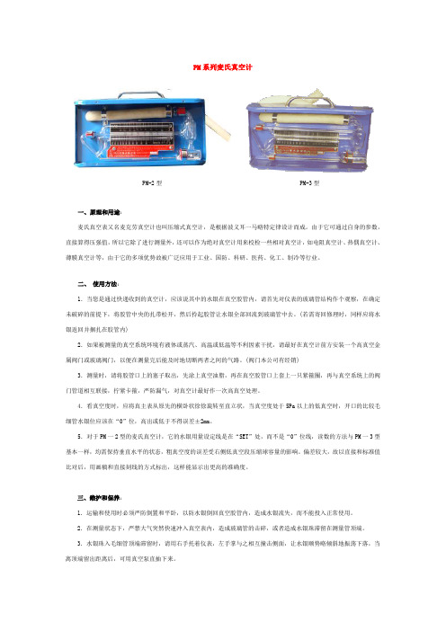
PM系列麦氏真空计PM-2型PM-3型一、原理和用途:麦氏真空表又名麦克劳真空计也叫压缩式真空计,是根据波义耳一马略特定律设计而成。
由于它可通过自身的参数,直接算得压强值,所以它除了进行测量外,还可以作为绝对真空计用来校检一些相对真空计,如电阻真空计、热偶真空计、薄膜真空计等,由于它的多项优势故被广泛应用于工业、国防、科研、医药、化工、制冷等行业。
二、使用方法:1.当您是通过快递收到的真空计,应该说其中的水银在真空胶管内,请首先对仪表的玻璃管结构作个观察,在确定未破碎的前提下,将胶管中央的扎带松开,然后拎起胶管让水银全部回流到玻璃管中去。
(若需寄回修理时,同样应将水银返回并捆扎在胶管内)2.如果被测量的真空系统环境有液体或蒸汽、高温或低温等不利因素干扰,请最好在真空计前方安装一个高真空金属阀门或玻璃阀门,以便在测量完后能及时地切断两者之间的气路。
(阀门本公司有经销)3.测量时,请将胶管口上的塞子取出,先涂上真空油脂,再在真空胶管口上套上一只紧箍圈,再与真空系统上的阀门管道相互联接,拧紧卡箍,严防漏气,对真空计最好作一次高真空处理。
4.看真空度时,应将真主表从原先的横卧状徐徐旋转至直立状,当真空度处于5Pa以上的低真空时,开口的比较毛细管水银位应该在“0”位,高出或低于不得误差±2mm。
5.对于PM一2型的麦氏真空计,它的水银用量设定线是在“SET”处,而不是“0”位线,读数的方法与PM一3型基本一样,均需保持垂直水平的状态,粗真空度的误差受右侧低真空段压缩球容量的影响。
偏差较大,故以直接和标准值比对后,用画稿和直接刻线的方式标出,这样能显示出更高的准确度。
三、维护和保养:1.运输和使用时必须严防倒置和平卧,以防水银倒回真空胶管内,造成水银流失,而不能投入正常使用。
2.在测量状态下,严禁大气突然快速冲入真空表内,造成玻璃管的击碎,或者造成水银珠滞留在测量管顶端。
3.水银珠入毛细管顶端滞留时,请用右手托着仪表,左手掌与之相互撞击侧面,让水银顺势略倾斜地振荡下落,当离顶端留出距离后,可用真空泵直抽下来。
FMS
1.1 集成化技术 过去制造系统中仅强调信息的集成,这是 不够的,现在更强调技术、人和管理的集成。 在开发制造系统时强调“多集成”的概念, 即信息集成、智能集成、串并行工作机制 集成及人员集成,这更适合未来制造系统的 需求。 1.2 网络技术 网络技术包括硬件与软件的实现。各种 通讯协议及制造自动化协议、信息通信接 口、系统操作控制策略等是实现各种制造 系统自动化的基础。
20世纪60年代,由英国Molins公司雇员 TheoWiiliam-son提出构思设想,并于1965年 Molins公司取得该项发明的专利,而FMS的 首创者则是美国MAALROSE公司,它于 1963年制造了世界上第一条加工多种柴油机 工件的数控自动线。1967年英国Molins公司 公布“系统24”,用计算机分散控制加工设备, 每天工作24h,使FMS的思想正式形成。
FMS-500 是一套适合于加工箱体类零件的中
小型弹性制造系统﹐它由两台卧式加工中 心﹑工件储运系统﹑刀具储运系统﹑控制系 统和管理决策支持系统所组成。 物料储运子系统又由物料运输有轨小车﹑中 央托盘库﹑装卸站所组成﹔ 刀具储运子系统由一台四自由度的指教坐标 机械人﹑中央刀库﹑刀具进出口站和对刀仪 组成﹐其系统组成如图。
FMS的构成与功能

柔性制造系统(FMS)柔性制造系统( Flexible Manufacturing System, FMS)是由统一的控制系统和物料输送系统联接起来的一组加工设备,能在不停机的情况下实现多品种工件的加工,并且具有一定管理功能的制造系统。
作为当代最先进的制造系统之一, FMS集高效率、高精度、高柔性于一体,使多品种小批量生产的生产过程也像大量生产一样实现了自动化。
其柔性主要体现在两个方面:一是能在同一时间内加工不同种类零件的不同工序;一是能选择不同的工艺路线加工一种零件的一组工序。
由于上述工艺上的高柔性,使FMS的设备利用率大大提高。
有资料表明,一般数控机床的切削时间约占一个工作班时间的10~30% ,而柔性生产系统的切削时间所占比例能达到50~90% 。
FMS的技术功能和生产能力在系统设计之初已经确定和保证,但实际中能否充分发挥它的能力,确保柔性的真正实现,则取决于投产后的作业调度与安排。
只有合理地安排工艺作业顺序、制定计划,才能合理有效地使用FMS系统。
1. FMS的组成典型的FMS按其功能, 由数控加工系统、物流系统和信息流系统。
(1)数控加工系统。
数控加工系统的功能是以任意顺序自动加工各种工件,并能自动地更换工件和刀具。
主要采用加工中心和数控车床,前者用于加工箱体类和板类零件,后者则用于加工轴类和盘类零件。
中、大批量少品种生产中所用的FMS,常采用可更换主轴箱的加工中心,以获得更高的生产效率。
加工系统的设备种类和数量取决于加工对象的工艺要求。
FMS的加工对象一般为回转体和非回转体两大类。
回转体类零件采用车削加工中心。
非回转体类零件比如箱体类、立方体类等则采用镗铣加工中心。
除此,一般还配备一定数量的数控机床或经过数控化改装的机床。
(2)物流系统在FMS中工件、工具流统称为物流系统,物流系统即物料贮运系统,是柔性制造系统中的一个重要组成部分。
一个工件从毛坯到成品的生产过程中,很大一部分时间都消耗于物料贮运系统中,合理的选择FMS的物料贮运系统,可以大大提高整个制造系统的柔性和效率。
说明fms的概念及组成

FMS的概念及组成一、概念FMS,全称是Flexible Manufacturing System,即柔性制造系统,是一种集成的、模块化的制造系统。
它结合了计算机、自动控制、通信和人工智能等多个领域的技术,旨在实现制造过程的自动化、柔性化和智能化。
FMS的主要特点是可以快速地适应不同种类和数量的产品生产,提高生产效率和灵活性。
二、组成1.加工设备:FMS中的加工设备可以根据不同的制造需求进行选择和配置,如数控机床、加工中心、激光切割机等。
这些设备可以独立完成或组合完成各种制造任务,并具有高精度、高效率的特点。
2.物流系统:物流系统是FMS的重要组成部分,负责将物料、半成品和成品在各个加工设备之间进行传输和储存。
物流系统通常包括输送带、AGV小车、仓储设备等,可以实现自动化、智能化的物料管理。
3.控制与监控系统:控制与监控系统是FMS的大脑,负责整个系统的协调和控制。
它可以根据生产计划和实际生产情况,动态调整各加工设备的运行状态,保证生产过程的稳定性和可靠性。
同时,监控系统可以实时监测设备的运行状态和生产质量,及时发现和解决异常情况。
4.信息管理系统:信息管理系统是FMS的神经网络,负责数据的采集、处理和传输。
它可以将生产计划、工艺参数、质量检测等信息进行集成管理,提供决策支持和服务支持。
同时,信息管理系统还可以实现与上层企业信息系统的集成,提高企业整体信息化水平。
5.维护与管理系统:维护与管理系统是FMS的保障体系,负责系统的维护和管理。
它可以根据设备的运行状态和维护历史,制定合理的维护计划,保证设备的正常运行和使用寿命。
同时,管理系统还可以对整个FMS的运行情况进行评估和优化,提高系统的生产效率和稳定性。
总之,FMS是一种高度集成、模块化和智能化的制造系统,它可以快速适应不同产品生产的需求,提高生产效率和灵活性。
FMS的组成包括加工设备、物流系统、控制与监控系统、信息管理系统和维护与管理系统等多个方面。
FMS概述

精选ppt
48
提醒信息
RWY/ILS FREQ ERROR 出现原因:当从进场页面上选定了着陆
跑道和仪表着陆系统后,飞机进近过程 中截获航向台的频率与进场页面上选定 的ILS频率不。 清除方法:按压CDU上的CLR键。
精选ppt
返回39
输入错误提醒信息
飞行员在一台CDU上输入的数据同时进 入两台CDU,但是,输入错误提醒信息 只在进行输入的那台CDU的草稿行出现, 以便进行输入的飞行员及时修改。
出现原因:数据格式或数值不正确,以 及飞行员进行了错误的操作。
消除办法:按压CDU上的CLR键首先清 除掉提醒信息,然后按压CLR键清除在 草稿行重现的错误数据。
(3)据实测的空中风结合ADC传来 的TAS计算偏流DA和应飞航向MH;
精选ppt
9
(二)IRS位置信号和无线电 导航位置修正
Nm 1 1
2
IRS传入基本导 航参数:地速、 位置、航向
采用VOR/DME 或DME/DME方 式对惯导位置进 行更新
精选ppt
10
(三)无线电导航设备的管理
可对VOR/DME信号人工或自动调谐
精选ppt
49
返回
惯性基准系统IRS输入的数据
位置 取IRU的加权平均值
速度 取IRU的算术平均值
姿态角、高度和升降速度 取A/P的 CMD (COMMAND) 方式对应 通道的那套IRU数据
精选ppt
返50回
飞行员必须输入以下两类数据
实施LNAV的数据
起飞机场、着陆机场以及计划的航路数据
精选ppt
7
pm32型控制器操作手册
pm32型新型控制器操作指南MARCO自动控制系统开发有限公司目录前言1. 控制器Booter说明2. 主机和交换机VLAN设置3. 新型控制器传程序4. 控制器贴膜按键介绍5. PM32系统操作说明前言随着上世纪80年代电子技术,现场控制技术和信息技术的快速发展,煤矿井工开采迫切需要利用先进的控制技术,改变其落后的生产工艺和控制水平。
煤矿井工生产的核心是综采工作面,如何大幅度提升综采工作面现代化和自动化控制水平成为当时煤矿现代化的首要任务。
在综采工作面装备中,液压支架占据着核心的位置,一方面液压支架要保障对工作面的有效支护,另外一方面又要作为推进动力,保障工作面推进效率。
如何提高液压支架对工作面的支护质量,如何提高采煤工作面的推进速度,成为煤矿现代化控制的重要要求。
在电液控制系统应用之前,液压支架采用手动操纵阀的控制方式,经历了本架手动控制,邻架手动控制,邻架液压先导控制的发展过程,手动控制方式的改进主要集中在控制的安全保障上,没有涉及到控制质量和控制效率的提高。
在上个世纪70年代末,英国人第一次提出了液压支架电液控制的概念,采用控制器,传感器和液压主阀替代手动操作阀,控制液压支架动作,保障对工作面顶板和煤壁的支护质量,提高工作面的推进速度。
随着电液控制系统在煤矿生产上的不断发展,支架电液控制系统已经超出了起初的控制范畴,从单纯控制液压支架,逐渐延伸到三机控制,泵站控制,采煤机等设备控制。
从本世纪初开始,网络技术逐步引进到煤矿生产中来,在融合电液控制系统后,实现了综采工作面自动化,实现了综采工作面设备高效管理,实现综采工作面生产过程优化控制。
在1996年,液压支架电液控制系统随着德国DBT公司成套综采设备进入到中国,应用在当时的神府矿区。
经过5年的使用和适应,电液控制系统高效性,高可靠性的优势逐渐显现出来,为国内各大煤矿所接受。
随着marco公司pm3型电液控制系统进入中国,通过和国内支架厂配套,解决了成套设备进口价格昂贵的劣势,尤其在2003年之后,以marco公司pm3系统为代表的液压支架电液控制系统在国内逐渐推广开来,电液控制系统应用也逐渐从简单的地质结构扩展到复杂的地质结构,从高端客户逐渐扩展到了绝大多数的煤矿用户,从支架控制扩展到综采工作面自动化。
PMS3003颗粒物传感器中文说明书V2.5-20160516
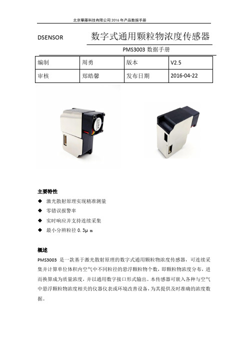
DSENSOR数字式通用颗粒物浓度传感器PMS3003数据手册主要特性◆激光散射原理实现精准测量◆零错误报警率◆实时响应并支持连续采集◆最小分辨粒径0.3μm概述PMS3003是一款基于激光散射原理的数字式通用颗粒物浓度传感器,可连续采集并计算单位体积内空气中不同粒径的悬浮颗粒物个数,即颗粒物浓度分布,进而换算成为质量浓度,并以通用数字接口形式输出。
本传感器可嵌入各种与空气中悬浮颗粒物浓度相关的仪器仪表或环境改善设备,为其提供及时准确的浓度数据。
工作原理本传感器采用激光散射原理。
即令激光照射在空气中的悬浮颗粒物上产生散射,同时在某一特定角度收集散射光,得到散射光强随时间变化的曲线。
进而微处理器利用基于米氏(MIE)理论的算法,得出颗粒物的等效粒径及单位体积内不同粒径的颗粒物数量。
传感器各功能部分框图如图1所示图1 传感器功能框图技术指标如表1所示表1 传感器技术指标注1:最大量程指本传感器确保PM2.5标准值最高输出数值不小于1000微克/立方米。
1000微克/立方米以上以实测为准。
注2:颗粒物浓度一致性数据为通讯协议中的数据2(见附录A)测量环境条件为20℃,湿度50%数字接口定义图2 接口示意图输出结果主要输出为单位体积内各浓度颗粒物质量浓度,单位为:微克/立方米。
输出分为主动输出和被动输出两种状态。
传感器上电后默认状态为主动输出,即传感器主动向主机发送串行数据,时间间隔为200~800ms,空气中颗粒物浓度越高,时间间隔越短。
主动输出又分为两种模式:平稳模式和快速模式。
在空气中颗粒物浓度变化较小时,传感器输出为平稳模式,即每三次输出同样的一组数值,实际数据更新周期约为2s。
当空气中颗粒物浓度变化较大时,传感器输出自动切换为快速模式,每次输出都是新的数值,实际数据更新周期为200~800ms。
典型电路连接图3 典型电路连接示意图电路设计应注意1.PMS3003需要5V供电,这是因为风机需要5V驱动。
FMS实训教学指导书资料
为实现本单元的控制功能,在主体结构的相应位置装设了光电传感器、磁性接近开关、微动开关等 检测与传感装置,并配备了步进电机、直流电机、直动气缸、电磁铁等执行机构和电磁阀、继电器等控
制元件。详见图 1-5 所示。
上 行
下 行
C
SQ1 SQ2
HL
M4
M5 S1
YM S2
逆
转
M1
S3
顺
SQ8 转 SQ3 SQ4
机电一体化柔性装配系统概述
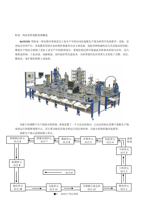
Me093399 型机电一体化教学系统是以工业生产中的自动化装配生产线为原型开发的教学、实验、实 训综合应用平台。本装置采用铝合金结构件搭建各分站主体设备,选取多种机械传动方式实现站间串联, 整条生产线充分展现了实际工业生产中的典型部分。系统控制过程中除涵盖多种基本控制方法外,还凸 现组态控制、工业总线、电脑视觉、实时监控等先进技术,为培养现代化应用型人才创设了完整、灵活、 模块化、易扩展的理想工业场景。
4.加盖单元(站点 4):通过直流电机带动蜗轮蜗杆,经减速电机驱动摆臂将上盖装配至工件主体, 完成装配后工件随托盘向下站传送。
5.穿销单元(站点 5):通过旋转推筒推送销钉的方法,完成工件主体与上盖的实体连接装配,完 成装配后的工件随托盘向下站传送。
6.模拟单元(站点 6):本站增加了模拟量控制的 PLC 特殊功能模块,以实现对完成装配的工件进 行模拟喷漆和烘干,完成喷漆烘干后的工件随托盘向下站传送。
图 1-1 工件主体上料单元
本单元在结构设计中涉及到行星齿轮系、螺纹微调机构、齿轮齿条机构、张紧机构等相关的机械原 理、机械零件知识,行星齿轮系的结构图如图 1-2 所示:
机构名称:行星齿轮系
A
B
工作特性:降速比大,增加扭矩
AFL FiberTech FT-PM3和FT-PM4光功率计说明书

is a high power meter with an input range of +26 dBM to 30 dBm. The FT-PM4 iscalibrated at 850, 980, 1310, 1490, 1550 and 1625 nm. All models can detect CW and270, 330, 1000 or 2000 Hz tones. FT-PM3 and FT-PM4 Optical Power Meters are factoryequipped with an integral 2.5 mm universal adapter and an FC thread-on adapter.Additional FC, SC and ST connector adapters are available.FiberTech Optical Power Meters are designed for ease of use. Each is equipped witha large, easy-to-read LCD, which shows the input power level, the remaining batterycapacity, and the status of the automatic power-off function. A user-selectable backlightenables the FT-PM3 and FT-PM4 to be used in dimly-lit spaces.FiberTech Optical Power Meters will operate for approximately 300 hours from a pair ofordinary AA alkaline batteries. An automatic power-down circuit optimizes battery life byshutting off after 5 minutes of operation.When paired with a NOYES Optical Light Source (such as the FiberTech FT-LS20,Contractor CSS1-SM or CSS1-MM, OLS1, OLS2, OLS4 or OLS7), FiberTech OpticalPower Meters provide installers, technicians, and field engineers with accurate, stablemeasurements of optical power levels and insertion loss characteristics. In addition,the tone detection capabilities also support optical fiber identification tasks when usedwith an appropriate light source. The FT-PM3 and FT-PM4 are fully N.I.S.T. traceable andcomply with CE and ROHS requirements.Features•Palm-sized, rugged, lightweight•Large LCD with backlight•Power measurements in dBm or μW•Insertion loss measurements in dB•270, 330, 1000, 2000 Hz tone detection•Long battery life with 2 x AA alkaline•Battery gauge and automatic power-off function•N.I.S.T traceable, CE and RoHS compliantApplications•Single-mode and multimode optical networks•Telco, broadband and enterprise networks•Optical insertion loss measurements•Optical fiber identification tasks or (800) 321-5298, (603) 528-7780 or (800) 321-5298, (603) 528-77802© 2012, AFL, all rights reserved. FTPM-00-2000 Revision 1D, 2012-05-08 Specifications are subject to change without notice .OPTICALFT-PM3FT-PM4Calibrated Wavelengths b 850, 1300, 1310, 1490, 1550 1625 nm 850, 980, 1310, 1490, 1550, 1625 nmDetector TypeInGaAs Hi Power InGaAs Measurement Range +6 to -70 dBm +26 to -50 dBm Tone Detect Range +6 to -50 dBm +6 to -45 dBm for 850 nm +26 to -30 dBm +26 to -25 dBm for 850 nmAccuracy c, d ±0.5 % (±0.2 dB)Resolution0.01 dB Measurement units dB, dBm, µWTones Detected 270, 330, 1000, 2000 HzGENERALConnector Interface Threaded adapter base mount with integrated 2.5 mm Universalaccepts FC, SC, and ST threaded connector adaptersPower 2 x AA batteries Battery Life>300 hoursOperating Temperature -10 ºC to +50 ºC, 90 % RH (non-condensing)Storage Temperature -30 ºC to 60 ºC, 90 % RH (non-condensing)Size 114 x 64 x 32 mm (4.5 x 2.5 x 1.3 in)Weight180 g (0.4 lb)Specifications aNotes:a. All specifications valid at 25 °C unless otherwise specified.b. Setup for wavelength calibrations:• MM calibration (850 and 1300 nm) with 50 micron fiber • SM calibration with 9/125 single-mode fiberc. Accuracy measured at 25 °C and -10 dBm per N.I.S.T standards.d. Typical.C E R T I F I E D9001ISON OY E S F I B E R S Y S T E M S Ordering InformationDESCRIPTIONAFL NO.Includes FT-PM3 with FC adapter, 2 x AA alkaline batteries, carry case and user's guide FT-PM3-FC Includes FT-PM4 with FC adapter, 2 x AA alkaline batteries, carry case and user's guide FT-PM4-FC 2900-FT-PM-FCMR FC Connector 2900-FT-PM-SCMR SC Connector 2900-FT-PM-STMRST ConnectorCalibration PlansMODEL 2 YR CAL PLAN 2 YR CAL PLUS PLAN AFL NO.AFL NO.FT-PM3-FC CAL2-00-FT-PM3CAL2-01-FT-PM3FT-PM4-FCCAL2-00-FT-PM4CAL2-01-FT-PM4FiberTech Optical Power MetersNOYES International Sales and Service Contact InformationAvailable at /NOYES/ContactsAFL recommends annual calibrations on NOYES Test and Inspection products. Prepaid Cal plans offer two annual calibrations at a discounted price, a convenient calibration expiration email service, express calibration services and access to the NOYES product knowledge base. Cal Plus plans offer the same services as the Cal plans with theaddition of a two year extended warranty (three years total coverage).。
PM32使用说明

P M32使用说明-CAL-FENGHAI.-(YICAI)-Company One1pm32型液压支架电液控制系统用户培训资料(工作面电控部分)目录前言................................................................................ 错误!未定义书签。
1 pm32电液控制系统的构成....................................... 错误!未定义书签。
2 pm32电液控制系统的设备和部件 ........................... 错误!未定义书签。
3 pm32电液控制系统的主要功能概述 ....................... 错误!未定义书签。
4 pm32支架控制器 ...................................................... 错误!未定义书签。
5 支架控制器应用程序菜单......................................... 错误!未定义书签。
6 传感器测量的菜单显示及操作 ................................. 错误!未定义书签。
7 “错误信息(ERROR MESSAGES)”菜单列的项目说明错误!未定义书签。
8 参数及其输入和“总体参数(GLOBAL PARAMETER)”参数列的项目说明.......................................................................... 错误!未定义书签。
9 功能的允许/禁止设定 ............................................... 错误!未定义书签。
10 “服务(SERVICE)”菜单列的项目说明 .............. 错误!未定义书签。
PM-3 麦氏真空表
PM-3 麦氏真空表麦氏真空表是用来测量高真空下压力的仪器。
相对于普通的压力计,麦氏真空表可以在更高的真空程度下进行测量。
1. 什么是麦氏真空表?麦氏真空表由美国物理学家John William Maclthaney发明,是一种用来测量真空环境下压力的设备。
麦氏真空表通过测量热阴极发射的电子流的大小,并根据该电子流的大小计算出真空环境下的压力大小。
麦氏真空表的使用范围从10-6至10-10毫米汞柱。
2. 麦氏真空表的优点麦氏真空表相对于普通的压力计有以下优点:2.1 高真空下依然有效普通压力计在高真空环境下很快就会失效,同时压力范围也很有限。
而麦氏真空表可以在更高的真空环境下进行测量,并且也可以测量到更小的压力范围。
2.2 精度更高由于麦氏真空表使用了精密的电子学技术,因此其测量精度比普通压力计更高。
麦氏真空表的测量结果更加可靠。
2.3 实用性更好麦氏真空表在测量高真空下的压力时,还可以直接获取其他相关信息,如气体种类、温度等。
这些数据对于科学研究和工业制造非常有用。
3. 使用麦氏真空表需要注意的问题麦氏真空表的使用需要进行正确的操作和维护。
以下是一些需要注意的问题:3.1 防止漏气麦氏真空表需要在真空环境下使用。
因此,在使用之前需要进行漏气检查以确保真空度。
漏气的主要原因是密封不良。
3.2 定期维护使用麦氏真空表需要定期维护。
主要包括清洁、校准和更换热阴极等。
3.3 正确使用使用麦氏真空表需要按照正确的使用方法进行。
例如,需要按照正确的电压和电流使用热阴极。
4. 结论麦氏真空表是一种测量高真空下压力的仪器。
相对于普通的压力计,麦氏真空表在高真空下依然有效,精度更高,实用性更好。
使用麦氏真空表需要注意防止漏气、定期维护和按照正确的使用方法进行操作。
