PPP.K2 ccie方案
CCIE-LAB考试排错部分案例详解(下)

CK:1.两幅图,二选一,问哪个网络更适合用组播。
不多解释了,最基本的理论。
2.vlan 1024为什么不能创建?3.port-security voilation restrict是什么作用?4.bgp的no-export是什么作用?TS:(设备都是模拟器)注意,拓扑跟这个基本一致,但是两处不一样。
(1) R3跟R22之间有设备,考的PPP验证。
(2) R9,R10都挂在R8下面,而不是这样串联的。
(一)、EIGRP域,有三个错误。
1、R25 ping不通R22的某个路由条目。
检查发现EIGRP邻居有问题,不停的up/down。
R25是DHCP server,R23、R24是ip address dhcp。
这个地方有两个错误:一是R19的地址池有问题,掩码用的是255.255.255.252,而自己的接口地址的掩码是255.255.255.248。
R17和R18获得的地址分别是.17/30和.18/30。
先把R17和R18接口下no ip address,然后修改R19的地址池。
再ip address dhcp就OK了。
二是EIGRP验证有问题。
3台路由器都配了key chain,但是R19在接口加载了,R17,R18没有加载。
2、NTP的问题。
R22是NTP server,R23,R24无法与其同步。
我把authentication的认证密码(md5)改了一下,就同步了。
3、PPP验证。
R22和与R3之间的某个设备,PPP无法正常建立连接。
两台设备上的username和对端ppp认证的hostname不匹配(二)、左边的OSPF域,有两个错误。
1、R15、R16无法建立OSPF邻接关系。
原因是R15上面对着R16的接口的帧中继的lmi-type有问题。
配成ansi是有问题的,R16上面啥也没配,默认是cisco。
把R15接口下的lmi-type干掉就行了。
2、R17无法ping通R21的某个接口。
PPP协议的配置与认证的课程设计

PPP协议的配置与认证摘要本课程设计主要是利用Boson模拟器Netsim搭建一个网络模拟环境,在此环境中建立一个的路由器的拓扑网,并对路由器进行PPP协议配置,待所有的路由器配置好后,利用PAP和CHAP对路由器进行认证,并分别对其进行测试。
根据认证和测试结果来分析该PPP协议的配置和认证的正确性。
若使用Ping命令后两者是连通的说明该配置和认证是成功的。
关键词BosonNetsim;网络仿真;PPP协议;PAP认证;CHAP认证1 引言广域网协议指Internet上负责路由器与路由器之间连接的数据链路层协议。
而常用的广域网有点对点的协议、高级数据链路控制协议、帧中继交换网、同步数据链路控制(SDLC)协议。
点对点协议(PPP)为在点对点连接上传输多协议数据包提供了一个标准方法。
PPP 最初设计是为两个对等节点之间的IP 流量传输提供一种封装协议。
在TCP-IP 协议集中它是一种用来同步调制连接的数据链路层协议(OSI 模式中的第二层),替代了原来非标准的第二层协议,即SLIP。
除了IP 以外PPP 还可以携带其它协议,包括DECnet 和Novell 的Internet 网包交换(IPX)。
本课程设计是搭建一个模拟环境,并在路由器上进行PPP配置,用PAP和CHAP对其进行认证和测试。
1.1课程设计的背景和目的计算机网络课程设计是《计算机网络》理论课的辅助环节。
PPP协议是目前广域网上应用最广泛的协议之一,它的优点在于简单、具备用户验证能力、可以解决IP分配等。
家庭拨号上网就是通过PPP在用户端和运营商的接入服务器之间建立通信链路。
目前,宽带接入正在成为取代拨号上网的趋势,在宽带接入技术日新月异的今天,PPP也衍生出新的应用。
因为PPP协议有简单完整的特点使所以得到了广泛的应用,相信在未来的网络技术发展中,它还可以发挥更大的作用。
通过本课程设计我们可以了解更多的广域网路由协议,通过实践可以加深对PPP 协议的配置和认证,尤其加深了对PAP和CHAP的工作原理的了解。
配置PPP验证时CISCO路由器CHAP认证配置-电脑资料

配置PPP验证时CISCO路由器CHAP认证配置-电脑资料本文详细的向大家描述了如何配置PPP验证和CHAP认证的配置,同时给出了配置的命令行,大家可以通过实例去了解一下配置过程,。
在配置PPP验证时有PAP和CHAP的选择,其中PAP为明文传送用户名和口令,不安全。
而CHAP则采用哈希值进行验证,口令不会在网上传送,所以安全性比较高。
CHAP认证也是CCNA课程PPP教学时所需掌握的基本配置,其配置如下:拓扑: RA DTE--------DCE RB--------------------------------------RA#conf tRA(config)#username RB password helloRA(config)#int s0RA(config-if)#encap pppRA(config-if)#ppp au chapRA(config-if)#end-------------------------------Router(config)#host RBRB(config)#username RA password helloRB(config)#int s0RB(config-if)#encap pppRB(config-if)#ppp auth chap%LINK-3-UPDOWN: Interface Serial0, changed state to up%LINEPROTO-5-UPDOWN: Line protocol on Interface Serial0, changed state to up------------------------------------------------------RA#sh int s0Serial0 is up, line protocol is up -------第一层二层UPHardware is HD64570Internet address is 1.1.1.1/30MTU 1500 bytes, BW 1544 Kbit, DLY 1000 usec, rely 255/255, load 1/255Encapsulation PPP, loopback not set, keepalive set (10 sec) LCP Open -----------打开Open: IPCP, CDPCP -----------打开Last input 00:00:00, output 00:00:00, output hang neverLast clearing of show interface counters neverQueueing strategy: fifo。
华为和思科路由器的互联配置
华为和思科路由器的互联配置三、配置文件说明思科路由器配置文件(部分):Current configuration:!version 12.1service timestamps debug uptimeservice timestamps log uptimeservice password-encryption!hostname Cisco //定义路由器主机名!enable secret 5 $QB$O1nBb A1olUQ JU1JQRUxNe$oHa0 //enable密码!no ip domain-lookup!interface Loopback0ip address 192.168.0.1 255.255.255.0 //定义Loopback地址,也可以不定义!interface Ethernet1/0description zhongxinip address 172.16.1.1 255.255.255.0!interface Serial2/0description connect to Huaweiencapsulation ppp //缺省的封装是HDLCip address 192.168.1.1 255.255.255.252!router ospf 10network 172.16.1.0 0.0.0.255 area 0 //定义area 0network 192.168.1.0 0.0.0.3 area 0 //定义area 0network 192.168.0.0 0.0.0.255 area 0 //如果没有定义Loopback地址,或者不希望//Loopback地址可OSPF路由,可以不需要!ip classlessno ip http server!line con 0transport input noneline aux 0line vty 0 4password 7 00450CB01A564A 1A0B //telnet密码,加密显示login!end华为路由器配置文件(部分):Current configuration!version 1.74local-user hw service-type administrator password cipher @'E8P0>+S>'-LGXJQ<%DJQ!!//定义用户hw,Adminstrator用户是路由器的管理员身份用户,拥有路由器所有命//令的执行权限,cipher方式下密码密文存放,simple方式下密码明文存放。
路由器实验四 PPP认证配置(PAP,CHAP)

CCNA实验集之十四PPP认证配置实验目的:1、掌握PPP pap/chap 验证的配置方法。
2、掌握debug ppp authentication 命令。
实验拓扑图:实验步骤及要求:(图中的实验分两次,先做第一个)1、每三个人组成一组,并且登陆到各自的设备上。
2、按拓扑图所示配置路由器的hostname;将enable secret 设置为cisco、enable p assword 设置为njut、VTY 线路密码为cisco。
3、配置各接口的IP 地址。
4、检验相邻设备的连通性。
5、按图中要求在三台路由器上配置PPP 单向验证,Florence 上的数据库为username njut password cisco。
Florence 做服务器:Florence(config)#username njut password ciscoFlorence(config)#int s0Florence(config-if)#encapsulation pppFlorence(config-if)#ppp authentication papFlorence(config)#int s1Florence(config-if)#encapsulation pppFlorence(config-if)#ppp authentication chapLondon 和Denver 做客户端:London(config)#int s1London (config-if)#encapsulation pppLondon (config-if)#ppp pap sent-username njut password ciscoDenver(config)#int s0Denver(config-if)#encapsulation pppDenver(config-if)# username njut password cisco6、在Florence 上使用debug ppp authentication 查看PPP 的认证情况。
PPP认证使用ppp chap hostname和 ppp authentication chap callin命令
PPP认证使用ppp chap hostname和ppp authentication chap callin命令前言PPP协商包括几个步骤例如链路控制协议(LCP)协商,认证和网络控制协议(NCP)协商。
如果双方不能对正确的参数达成协议,则连接被终止。
一旦链路建立,双方使用在LCP协商期间决定的认证协议互相验证。
认证一定是成功的在开始NCP协商之前。
PPP支持二个认证协议:密码验证协议(PAP)和质询握手验证协议(CHAP)。
使用的组件本文的信息根据以下的软件及硬件版本。
Cisco IOS® 软件版本11.2 以上背景理论PAP验证介入用户名和口令在明文横跨链路其中被发送的一只双向握手; 因此,PAP验证不提供任何防护放音和线路探测。
CHAP认证另一方面,使用三方握手周期验证远程节点的身份。
在PPP链接建立之后,主机寄发一个"挑战"消息到远程节点。
远程节点回应带有使用一个单向散列函数计算的值。
主机检查回应其期望的Hash值的自己的计算。
如果值配比,认证被承认; 否则,连接被终止。
配置在此部分,您介绍用信息配置在本文描述的功能。
注意:找到其它信息关于用于本文的命令,使用IOS命令查找工具配置单向CHAP验证当二个设备正常使用CHAP认证时,每边派出另一边由挑战者回应和验证的挑战。
其中每一支持独立地互相验证。
如果想要用不由呼叫路由器或设备支持认证的非Cisco路由器经营,您必须使用 ppp authentication chap callin命令。
当使用 ppp authentication命令带有呼入关键字时,接入服务器只将验证远端设备如果远端设备发起呼叫(例如,如果远端设备"调用在 ")。
在这种情况下,认证在仅流入的(收到的)呼叫指定。
配置用户名与路由器名字不同当遥控Cisco路由器接通到Cisco或一个非Cisco的中央路由器不同的管理控制,网络服务提供商(ISP)时,或者轮循中央路由器,配置是与主机名不同的认证用户名是必要的。
ppp模式的实施步骤和思路

PPP模式的实施步骤和思路1. 什么是PPP模式PPP(Point-to-Point Protocol)是一种数据链路层协议,用于在两个节点间建立直接的点对点连接。
PPP模式可以用于建立网络连接,通常用于拨号上网、远程访问和虚拟专用网络(VPN)等场景。
在PPP模式下,两个节点通过协商建立连接参数、认证和数据传输等过程来进行通信。
2. PPP模式的实施步骤以下是PPP模式的实施步骤:步骤1:协商连接参数在建立PPP连接之前,两个节点需要协商连接参数。
这些参数包括传输协议、压缩算法、认证方法等。
通过协商,双方确定使用的协议和参数,以确保双方能够正常通信。
步骤2:身份认证在PPP连接建立之前,通常需要进行身份认证。
身份认证可以使用用户名和密码进行,也可以使用其他认证方法,如基于证书的认证。
认证的目的是确保连接的安全性和合法性。
步骤3:链路控制协议的建立PPP使用链路控制协议(LCP)来管理连接状态和协商选项。
在建立连接之后,双方会通过LCP协商来确定是否启用某些特性和选项,如帧同步、错误检测和报文封装等。
LCP的建立确保了连接的稳定性和可靠性。
步骤4:网络控制协议的建立在LCP协商完成之后,通常还需要建立网络控制协议(NCP)来激活IP或其他网络协议。
NCP协议用于为PPP连接提供网络层协议的支持,如IP、IPX和AppleTalk等。
通过NCP的建立,双方可以在PPP连接上传输网络层数据。
步骤5:数据传输一旦PPP连接建立完成,双方可以开始进行数据传输。
数据传输可以使用TCP/IP协议栈进行,实现可靠的数据传输。
通过PPP连接,可以实现拨号上网、远程访问和虚拟专用网络等功能。
3. PPP模式的实施思路在实施PPP模式时,需要考虑以下几点思路:思路1:确定PPP连接的需求和目标在实施PPP模式之前,需要明确连接的需求和目标。
这包括连接的用途、连接的安全性需求以及使用的协议和参数等。
明确需求和目标可以帮助选择合适的实施方案和配置参数。
31、PPP概述
CCNA学习笔记31--PPP概述(2010-07-05 20:56:06)转载分类:CCNA自学笔记篇标签:杂谈PPP(point to point )点对点协议。
是广域网的封装协议、运行在点对点链路中第二层数据链路层的协议、目前我们广泛使用的ADSL使用的是PPPoE协议。
它就是基于PPP协议的。
它就是通过将PPP的帧封装在以太网中运行的。
PPP协议的优点1.支持同步或异步传输2.支持多种网络层协议3.支持错误检测4.支持网络层地址协商5.支持用户认证(PAP/CHAP)6.运行进行数据压缩LCP(链路控制协议):主要是用来建立、控制数据链路的。
在LCP层要协商的参数:1.MRU :最大接收单元2.认证协议3.链路压缩、针对于数据的压缩4.多链路捆绑可以增加带宽、降低延迟NCP(网络控制协议):支持多种网络协议。
在NCP层要协商的参数:1.IP地址协商点对点链路允许动态分配IP地址、动态协商IP地址2.TCP/IP头压缩必须是双方都要配置压缩、否则不生效重点理解PPP的两种认证方式PAP: 两次握手认证过程被认证方发起明文发送密码认证过程CHAP:三次握手认证过程主认证方发起不发送明文密码认证、发送的是经过MD5加密过的HASH值注意:CHAP认证发送的字段(01 握手认证的序列号、id 唯一标识一次认证过程的,固定不变、随机数据根据某种算法算出的随机数据,发送时自己还保留一份、主认证方的名字)四个字段理解其认证的过程、PAP是怎么认证的、CHAP又是怎么认证的。
两次握手具体过程是怎么样的?三次握手具体过程又是怎么样的?要了解。
HCIE面试笔记-PPP
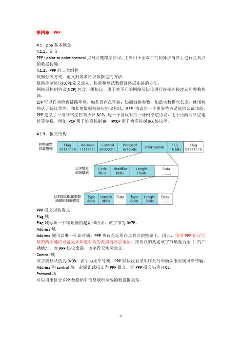
第四章PPP4.1、ppp基本概念4.1.1、定义PPP(point-to-point protocol点对点链路层协议,主要用于全双工的同异步链路上进行点到点的数据传输。
4.1.2、PPP的三大组件数据分装方式:定义封装多协议数据包的方法。
链路控制协议(LCP):定义建立、协商和测试数据链路层连接的方法。
网络层控制协议(NCP):包含一组协议,用于对不同的网络层协议进行连接连接建立和参数协商。
LCP可以自动检查链路环境,如是否存在环路;协商链路参数,如最大数据包长度,使用何种认证协议等等。
和其他数据链路层协议相比,PPP协议的一个重要特点是提供认证功能。
PPP定义了一组网络层控制协议NCP,每一个协议对应一种网络层协议,用于协商网络层地址等参数,例如IPCP用于协商控制IP,IPXCP用于协商控制IPX协议等。
4.1.3、报文结构PPP报文封装格式Flag域Flag域标识一个物理帧的起始和结束,该字节为0x7E。
Address域Address域可以唯一标识对端。
PPP协议是运用在点到点的链路上,因此,使用PPP协议互联的两个通信设备无须知道对端的数据链路层地址。
按协议的规定该字节填充为全1的广播地址。
对PPP协议来说,该字段无实际意义。
Control域该字段默认值为0x03,表明为无序号帧,PPP默认没有采用序列号和确认来实现可靠传输。
Address和control域一起标识此报文为PPP报文,即PPP报文头为FF03。
Protocol域可以用来区分PPP数据帧中信息域所承载的数据报类型。
LCP报文封装格式:Code域代码域长度为一个字节,主要用于标识LCP数据报文的类型Indentifier域标识域为1个字节,用来匹配请求和相应,当标识域值为非法时,该报文将被丢弃通常一个配置请求报文的id是从0x01开始逐步加1的。
当对端接收到该请求报文后,无论使用何种报文回应对方,但必须要求回应报文中的ID要与接收报文中的ID一致。
思科CiscoPPP协议原理与配置方法解析
思科CiscoPPP协议原理与配置⽅法解析本⽂讲述了思科Cisco PPP协议原理与配置⽅法。
分享给⼤家供⼤家参考,具体如下:1. PPP(点到点协议)点到点协议,⾮cisco产品串⾏接⼝默认的⼆层封装技术,属于点到店⽹络类型是对HDLC的升级1.1 升级点:拨号⾮直连⽹段ip地址,也可以互相访问;⾃动学习对端接⼝的ip地址,⽣成直连主机路由⾝份核实--认证建⽴虚链路---分配ip地址1.2 PPP认证的两种⽅式1.pap明⽂传输明⽂和密码—⽀持双⽅认证,认证⽤户名和密码可以不⼀致2.chap质检握⼿⾝份核实(密码被隐藏)--在chap双⽅认证中,双⽅密码必须保持⼀致,否则认证失败1.3配置1.pap配置主认证⽅:定义密钥数据库,接⼝启⽤papR1(config)#username a password 12345R1(config)#int s0/0R1(config-if)#en pppR1(config-if)#ppp au pap被认证⽅:发送pap的⽤户名和密码R2(config)#int s0/0R2(config-if)#encapsulation pppR2(config-if)#ppp pap sent-username a password 123452. chap配置1. 携带主机名主认证⽅:R3(config)#int s1/0R3(config-if)#en pppR3(config-if)#ppp authe chapR3(config-if)#username R4 password 1234被认证⽅:R4(config)#int s1/0R4(config-if)#en pppR4(config-if)#exR4(config-if)#username R3 password 1234 2.不携带主机名主认证⽅:R5(config)#int s1/0R5(config-if)#en pppR5(config-if)#ppp authe chapR5(config-if)#username a password 123456被认证⽅:R6(config)#int s1/0R6(config-if)#en pppR6(config-if)#ppp chap password 123456R6(config-if)#ppp chap hostname a。
区块链物联网设备与无线访问点双向认证方案

区块链物联网设备与无线访问点双向认证方案随着物联网技术的发展,越来越多的物联网设备被广泛应用于各种领域,如智能家居、智能交通、智慧城市等。
无线访问点也在各种场景下得到了广泛的应用,它们为设备提供了无线接入的能力,为大家的日常生活和工作带来了极大的便利。
随着物联网设备的数量不断增加和使用场景的多样化,设备与无线访问点之间的认证安全问题也变得越来越重要。
为了保障物联网设备与无线访问点之间的安全通信,需要采取一种双向认证方案,而区块链技术正是一个很好的选择。
一、目前存在的问题在传统的物联网设备与无线访问点通信过程中,存在着一些安全隐患。
由于物联网设备数量多、分布广,设备本身的安全性难以保证,容易受到攻击。
无线访问点作为连接设备和网络的关键节点,同样也容易受到攻击。
传统的认证方式往往只是单向认证,即设备验证访问点的身份,而无法保证访问点也能验证设备的身份。
这就使得恶意攻击者有可能通过仿冒合法设备的方式,进入网络进行攻击,导致网络安全问题。
为了解决这些安全隐患,需要一种更加安全可靠的双向认证方案,确保物联网设备与无线访问点之间的通信安全。
二、区块链技术在物联网设备与无线访问点通信中的应用1. 设备身份认证物联网设备在接入网络之前,首先需要进行设备身份认证。
在区块链中,可以为每个物联网设备建立一个独特的标识,即设备身份信息。
当设备需要接入网络时,首先将自己的身份信息上传到区块链网络中,然后由区块链网络进行验证和存储。
这样一来,即使设备受到攻击,其身份信息也无法被篡改,保证了设备的身份真实性和唯一性。
3. 双向认证过程在设备和访问点完成身份认证之后,双向认证过程就可以开始了。
设备首先向访问点发送自己的身份信息,然后访问点通过区块链网络验证设备的身份信息,确认设备的合法性后,再向设备发送自己的身份信息,设备同样通过区块链网络验证访问点的身份信息,确认访问点的合法性。
只有在双向认证通过后,设备和访问点之间才能建立安全的通信连接,保证通信过程的安全性和可靠性。
一CISCO路由器ppp协议配置和认证

路由器ppp协议配置和认证:Router 0 的配置:--- System Configuration Dialog ---Continue with configuration dialog? [yes/no]: noPress RETURN to get started!Router>enRouter>enableRouter#confRouter#configureRouter#configure terminalEnter configuration commands, one per line. End with CNTL/Z.Router(config)#intRouter(config)#interface fRouter(config)#interface fastEthernet 0/0Router(config-if)#ip addRouter(config-if)#ip address 2.2.2.1 255.0.0.0Router(config-if)#no shutRouter(config-if)#no shutdown%LINK-5-CHANGED: Interface FastEthernet0/0, changed state to up %LINEPROTO-5-UPDOWN: Line protocol on Interface FastEthernet0/0, changed state to upRouter(config-if)#exitRouter(config)#intRouter(config)#interface sRouter(config)#interface serial 0/0Router(config-if)#ip addRouter(config-if)#ip address 1.1.1.1 255.0.0.0Router(config-if)#nos hutRouter(config-if)#no shutRouter(config-if)#no shutdown%LINK-5-CHANGED: Interface Serial0/0, changed state to downRouter(config-if)#Router(config-if)#%LINK-5-CHANGED: Interface Serial0/0, changed state to upRouter(config-if)#exitRouter(config)#ip routRouter(config)#ip route 3.3.3.0 255.0.0.0 sRouter(config)#ip route 3.3.3.0 255.0.0.0 serial 0/0Router(config)#nos hutRouter(config)#no shutRouter(config)#end%SYS-5-CONFIG_I: Configured from console by consoleRouter#show ip rouRouter#show ip routeCodes: C - connected, S - static, I - IGRP, R - RIP, M - mobile, B - BGPD - EIGRP, EX - EIGRP external, O - OSPF, IA - OSPF inter area N1 - OSPF NSSA external type 1, N2 - OSPF NSSA external type 2E1 - OSPF external type 1, E2 - OSPF external type 2, E - EGP i - IS-IS, L1 - IS-IS level-1, L2 - IS-IS level-2, ia - IS-IS inter area* - candidate default, U - per-user static route, o - ODR P - periodic downloaded static routeGateway of last resort is not setC 2.0.0.0/8 is directly connected, FastEthernet0/0Router#ping 3.3.3.2Type escape sequence to abort.Sending 5, 100-byte ICMP Echos to 3.3.3.2, timeout is 2 seconds: .....Success rate is 0 percent (0/5)Router#confRouter#configureRouter#configure terminalEnter configuration commands, one per line. End with CNTL/Z.Router(config)#intRouter(config)#interface sRouter(config)#interface serial 0/0Router(config-if)#enRouter(config-if)#encapsulation ?frame-relay Frame Relay networkshdlc Serial HDLC synchronousppp Point-to-Point protocolRouter(config-if)#encapsulation ppp ?<cr>Router(config-if)#encapsulation pppRouter(config-if)#?bandwidth Set bandwidth informational parametercdp CDP interface subcommandsclock Configure serial interface clockdelay Specify interface throughput delaydescription Interface specific descriptionencapsulation Set encapsulation type for an interfaceexit Exit from interface configuration modeframe-relay Set frame relay parametersip Interface Internet Protocol config commandskeepalive Enable keepaliveno Negate a command or set its defaultsppp Point-to-Point Protocolshutdown Shutdown the selected interfaceRouter(config-if)#no shutRouter(config-if)#no shutdownRouter(config-if)#exitRouter(config)#intRouter(config)#interface sRouter(config)#interface serial 0/0Router(config-if)#clRouter(config-if)#clock ?rate Configure serial interface clock speedRouter(config-if)#clock rRouter(config-if)#clock rate 64000Router(config-if)#%LINEPROTO-5-UPDOWN: Line protocol on Interface Serial0/0, changed state to upnoshutRouter(config-if)#no shutRouter(config-if)#no shutdownRouter(config-if)#Router(config-if)#Router#confRouter#configureRouter#configure terminalEnter configuration commands, one per line. End with CNTL/Z.Router(config)#interface serial 0/0Router(config-if)#ppp ?authentication Set PPP link authentication methodpap Set PAP authentication parametersRouter(config-if)#ppp aRouter(config-if)#ppp authentication chRouter(config-if)#ppp authentication chap%LINEPROTO-5-UPDOWN: Line protocol on Interface Serial0/0, changed state to downRouter(config-if)#exitRouter(config)#hoRouter(config)#hostname 111111(config)#enable password 112111(config)#?Configure commands:access-list Add an access list entrybanner Define a login bannerboot Modify system boot parameterscdp Global CDP configuration subcommandsclock Configure time-of-day clockconfig-register Define the configuration registercrypto Encryption moduledo To run exec commands in config modeenable Modify enable password parametersend Exit from configure modeexit Exit from configure modehostname Set system's network nameinterface Select an interface to configureip Global IP configuration subcommandsline Configure a terminal lineno Negate a command or set its defaultsrouter Enable a routing processservice Modify use of network based servicesusername Establish User Name Authentication111(config)#username 221 p111(config)#username 221 password 222111(config)#111(config)#Router 1 配置:--- System Configuration Dialog ---Continue with configuration dialog? [yes/no]: noPress RETURN to get started!Router>enRouter>enableRouter#confRouter#configureRouter#configure terminalEnter configuration commands, one per line. End with CNTL/Z.Router(config)#intRouter(config)#interfaceRouter(config)#interface fRouter(config)#interface fastEthernet 0/0Router(config-if)#ip addRouter(config-if)#ip address 3.3.3.1 255.0.0.0Router(config-if)#no shutRouter(config-if)#no shutdown%LINK-5-CHANGED: Interface FastEthernet0/0, changed state to up%LINEPROTO-5-UPDOWN: Line protocol on Interface FastEthernet0/0, changed state to upRouter(config-if)#exitRouter(config)#intRouter(config)#interface fRouter(config)#interface sRouter(config)#interface serial 0/0Router(config-if)#ip addRouter(config-if)#ip address 2.2.2.2 255.0.0.0Router(config-if)#no shutRouter(config-if)#no shutdown%LINK-5-CHANGED: Interface Serial0/0, changed state to upRouter(config-if)#exitRouter(config)#ip rouRouter(config)#intRouter(config)#interface sRouter(config)#interface serial 0/0Router(config-if)#ip addRouter(config-if)#ip address 1.1.1.2 255.0.0.0Router(config-if)#nos hutRouter(config-if)#no shutRouter(config-if)#no shutdownRouter(config-if)#exitRouter(config)#ip rouRouter(config)#ip route 1.1.1.0 255.0.0.0 sRouter(config)#ip route 2.2.2.0 255.0.0.0 serial 0/0Router(config)#exit%SYS-5-CONFIG_I: Configured from console by consoleRouter#show ip rouRouter#show ip routeCodes: C - connected, S - static, I - IGRP, R - RIP, M - mobile, B - BGPD - EIGRP, EX - EIGRP external, O - OSPF, IA - OSPF inter area N1 - OSPF NSSA external type 1, N2 - OSPF NSSA external type 2E1 - OSPF external type 1, E2 - OSPF external type 2, E - EGP i - IS-IS, L1 - IS-IS level-1, L2 - IS-IS level-2, ia - IS-IS inter area* - candidate default, U - per-user static route, o - ODR P - periodic downloaded static routeGateway of last resort is not setC 3.0.0.0/8 is directly connected, FastEthernet0/0Router#confRouter#configureRouter#configure terminalEnter configuration commands, one per line. End with CNTL/Z.Router(config)#intRouter(config)#interface sRouter(config)#interface serial 0/0Router(config-if)#enRouter(config-if)#encapsulation ?frame-relay Frame Relay networkshdlc Serial HDLC synchronousppp Point-to-Point protocolRouter(config-if)#encapsulation pppRouter(config-if)#no shutRouter(config-if)#no shutdownRouter(config-if)#%LINEPROTO-5-UPDOWN: Line protocol on Interface Serial0/0, changed state to upRouter#Router#confRouter#configureRouter#configure terminalEnter configuration commands, one per line. End with CNTL/Z.Router(config)#intRouter(config)#interface sRouter(config)#interface serial 0/0Router(config-if)#ppp ?authentication Set PPP link authentication methodpap Set PAP authentication parametersRouter(config-if)#ppp auRouter(config-if)#ppp authentication ?chap Challenge Handshake Authentication Protocol <CHAP>pap Password Authentication Protocol <PAP>Router(config-if)#ppp authentication chRouter(config-if)#ppp authentication chapRouter(config-if)#no shutdownRouter(config-if)#exitRouter(config)#hosRouter(config)#hostname 221221(config)#enable ?password Assign the privileged level passwordsecret Assign the privileged level secret221(config)#enable p221(config)#enable password 222221(config)#us221(config)#username 111 ?password Specify the password for the user221(config)#username 111 pa221(config)#username 111 password 112?LINE221(config)#username 111 password 112 ?<cr>221(config)#username 111 password 112221(config)#221(config)#。
PPP详解
PPP详解1.简介PPP是为了在点对点物理链路(例如RS232串口链路、电话ISDN 线路等)上传输OSI模型中的网络层报文而设计的,它改进了之前的一个点对点协议–SLIP协议–只能同时运行一个网络协议、无容错控制、无授权等许多缺陷,PPP是现在最流行的点对点链路控制协议。
这种连接提供了同时的双向的全双工操作,并且假定数据包是按顺序投递的。
PPP连接提供了一种广泛的解决办法,方便地将多种多样不同的值作为最大接收单元的值。
填充域在传输中,信息域可能会由附加任意数目的字节填充至最大接收单元长度。
这由每个协议负责将信息域和填充域区分开来。
PPP协议概览标准的HDLC封装只支持高层的IP协议,不支持其他高层协议。
思科对标准帧协议进行了改进,增加了协议域字段,来支持多种网络层协议。
思科改进的HDLC可用于在思科的设备之间进行点到点连接。
当连接非思科的设备时,PPP是比较可行的,因为所有厂家实现的PPP 都是相同的。
PPP协议和大多数硬件兼容,且PPP协议能够承载多种三层协议的数据。
PPP是一种数据链路层协议,遵循HDLC(高级数据链路控制协议)族的一般报文格式。
PPP是为了在点对点物理链路(例如RS232串口链路、电话ISDN线路等)上传输OSI模型中的网络层报文而设计的,它改进了之前的一个点对点协议–SLIP协议–只能同时运行一个网络协议、无容错控制、无授权等许多缺陷,PPP是现在最流行的点对点链路控制协议。
PPP协议主要包括三部分:LCP(Link Control Protocol)链路控制协议、NCP (Network Control Protocol)网络控制协议和PPP的扩展协议(如Multilink Protocol)。
PPP协议默认是不进行认证配置参数选项的协商,它只作为一个可选的参数,当点对点线路的两端需要进行认证时才需配置。
LCP是PPP协议的一个子集。
为了能适应复杂多变的网络环境,PPP协议提供了一种链路控制协议来配置和测试数据通信链路,它能用来协商PPP协议的一些配置参数选项;处理不同大小的数据帧;检测链路环路、一些链路的错误;终止一条链路。
斐讯酒店无线网络覆盖组网方案

酒店无线网络覆盖组网解决方案公司2013年09月一、实施方案设计:1、需求分析本项目旨在酒店现有楼宇骨干网的基础上,建设一套安全、快速、可靠的无线网络来覆盖整个酒店的公共区域和客房区域。
本项目主要是为了解决旅游和入住本酒店的商务客人的互联网接入和会议需要,为他们提供方便、灵活、高效的无线网络连接服务。
本项目大楼内我们将采用上海斐讯2800系列室内型大功率无线AP进行无线网络覆盖;同时实现无线网络与有线网络必须有效连接,并可在现有网络基础上进行扩充,为将来的各种无线网络终端设备提供网络基础平台。
由于酒店业务发展,需要在办公区内部署宽带网络连接,包括ERP等业务。
基于有线网络布线施工进度慢,工程成本高且复杂。
相对于无线网络,快速,低成本建设,且可以提供高速网络接入,能满足用户实际网络需求,可达到无处不在的网络服务。
为未来酒店拓展信息服务和酒店形象,提高网络使用价值,打好了基础。
酒店无线覆盖基本架构图如下图所示:图1 无线覆盖系统架构图2、方案设计为了本次方案能达到比较好的服务质量。
可采用基于802.11g的大功率的无线以太网产品,实现酒店大楼客房全区域无线网络信号覆盖。
在此建议方案中,根据酒店的具体要求和环境。
酒店走道大概有60米长,每层大约有30多间客房。
为了使上网能够达到较快速度。
并且要考虑到酒店内部可以运行ERP系统。
借此,我们将建议采用上海斐讯2800系列大功率无线AP进行客房和大厅的无线网络覆盖,达到高速无线共享上网。
本项目接入部分,前端做无线覆盖的FAP-2800无线AP通过网线接入到中心无线集中管理设备FAC-5000系列上,再接入到酒店的中心机房,完成整个无线网络覆盖部分。
二、产品应用及说明1、产品应用无线网络室内覆盖的功能就是利用无线网络设备对特定的工作区域实现无线信号的覆盖,确保位于这一区域的无线网络用户能通过无线网络设备实现网络的连接和资源的共享。
无线网络的室内覆盖在办公区域,酒店覆盖和特定功能区特别有效,这些特定区域用户的特点是:广泛使用笔记本电脑、掌上电脑、PDA等移动通讯设备,工作位置的流动性特别大,客户只有在特定的时间才会在某一固定区域上网。
华为路由器ppp认证和pppoe
PAP认证:只支持明文,并且通告密码CHAP认证:支持密文,不通告密码而是通告HASH值。
PAP认证报文类型:Authenticate-Request:用于被验证方发送用户名和密码,Data字段包含明文用户名和密码信息Authenticate-Ack:用于验证方发送验证成功信息,Data字段可以包含文本提示信息Authenticate-Nak:用于验证方发送验证失败信息,Data字段可以包含文本提示信息PPPoE报文是使用Ethernet格式进行封装的,Ethernet中各字段解释如下:DMAC:表示目的设备的MAC地址,通常为以太网单播目的地址或者以太网广播地址(0xFFFFFFFF)。
SMAC:表示源设备的以太网MAC地址。
Type:表示协议类型字段,当值为0x8863时表示承载的是PPPoE发现阶段的报文。
当值为0x8864时表示承载的是PPPoE会话阶段的报文。
PPPoE字段中的各个字段解释如下:VER:表示PPPoE版本号,值为0x01。
Type:表示类型,值为0x01。
Code:表示PPPoE报文类型,不同取值标识不同的PPPoE报文类型。
PPPoE会话ID,与以太网SMAC和DMAC一起定义了一个PPPoE会话。
Length:表示PPPoE报文的Payload长度,不包括以太网头部和PPPoE头部的长度。
PADI(PPPoE Active Discovery Initiation)报文:用户主机发起的PPPoE服务器探测报文,目的MAC地址为广播地址。
PADO(PPPoE Active Discovery Offer)报文:PPPoE服务器收到PADI报文之后的回应报文,目的MAC地址为客户端主机的MAC地址。
PADR(PPPoE Active Discovery Request)报文:用户主机收到PPPoE服务器回应的PADO报文后,单播发起的请求报文,目的地址为此用户选定的那个PPPoE服务器的MAC地址。
CCNA十四点对点PPP协议PAP认证

实验十五点对点PPP协议PAP认证一、实验目的和要求•了解点对点协议(PPP)的工作原理•掌握PPP 协议两种认证方式的特点和区别•掌握PPP 协议的配置以及PAP 认证协议的配置二、实验设备模拟软件:Cisco PacketTracer53_setup_no_tutorials设备:路由器2 台,串口线一根三、实验内容在两台路由器上配置PAP 或CHAP 验证协议,在链路协商时保证安全验证。
链路协商时密码以密文的方式传输,更安全。
具体包括PAP 单向认证和PAP 双向认证,以及CHAP 单向或双向认证。
四、实验拓扑1、PAP单向认证2、PAP双向认证五、背景描述你是公司的网络管理员,公司为了满足不断增长的业务需求,申请了专线接入,你的客户端路由器与ISP 进行链路协商时要验证身份,配置路由器保证链路的建立,并考虑其安全性。
六、相关知识1、PPP 协议点到点协议(point to point protocol,PPP)是IETF(internet engineering task force,因特网工程任务组)推出的点到点类型线路的数据链路层协议。
它解决了slip 中的问题,并成为正式的因特网标准。
PPP 支持在各种物理类型的点到点串行线路上传输上层协议报文。
PPP 有很多丰富的可选特性,如支持多协议、提供可选的身份认证服务、可以以各种方式压缩数据、支持动态地址协商、支持多链路捆绑等等。
这些丰富的选项增强了PPP 的功能。
同时,不论是异步拨号线路还是路由器之间的同步链路均可使用。
因此,应用十分广泛。
PPP 提供了两种可选的身份认证方法:口令验证协议PAP(password authentication protocol,PAP)和质询握手协议(challenge handshake authentication protocol,chap)。
如果双方协商达成一致,也可以不使用任何身份认证方法。
2、PAP 验证原理PAP 是一个简单的、实用的身份验证协议。
- 1、下载文档前请自行甄别文档内容的完整性,平台不提供额外的编辑、内容补充、找答案等附加服务。
- 2、"仅部分预览"的文档,不可在线预览部分如存在完整性等问题,可反馈申请退款(可完整预览的文档不适用该条件!)。
- 3、如文档侵犯您的权益,请联系客服反馈,我们会尽快为您处理(人工客服工作时间:9:00-18:30)。
内部资料K-2Version: 2.0内部资料:不得外泄,违者严惩!K-21、Layer2 Technologies1.1-VTP is transparent●PPP on the serial links R2 & R3●VLANs==================================================================================== Solution:====================================================================================1.2.-Layer 2 Provisioning a robust L2●Ensure that spanning tree enters the forwarding state immediately only for access switchports bypassingthe listening and learning states.●Avoiding transmitting BPDUs on any access switchport on any of these ports, the ports should beshutdown immediately.●Ensure that all four switches are able to read to unidirectional link failure for any switch to switchport theaffected port should be disabled in the event failure.==================================================================================== Solution:SW1-SW2-SW3-SW4spanning-tree mode rpvstspanning-tree portfast defaultspanning-tree portfast bpduguard defaultinterface ranger fastethernet0/19-24udld port aggressive==================================================================================== ✧SW3 F1/10 port may recive some bpdu from BB3,disable the bpduguard fuction on this port==================================================================================== SW3int f0/10spanning-tree bpduguard disable====================================================================================1.3. –Frame-Relay●Use Cisco LMI on FR Switch on R5 and autosense on R1 & R3.●Do not use any static frame-relay maps.●Use frame-relay encapsulation as “cisco”.●Use DLCI assignment table below==================================================================================== Solution:R5:frame-relay switchinginterface Serial1/0no ip addressencapsulation frame-relayclock rate 64000frame-relay intf-type dceframe-relay route 231 interface Serial1/1 233interface Serial1/1no ip addressencapsulation frame-relayclock rate 64000frame-relay intf-type dceframe-relay route 233 interface Serial1/0 231R1interface Virtual-Template1no ip addressppp multilinkppp multilink group 1interface Serial1/1no ip addressencapsulation frame-relayserial restart-delay 0no arp frame-relayno frame-relay inverse-arpinterface Serial1/1.13 point-to-pointframe-relay interface-dlci 231 ppp Virtual-Template1R3:interface Virtual-Template1no ip addressppp multilinkppp multilink group 1interface Serial1/0no ip addressencapsulation frame-relayserial restart-delay 0no arp frame-relayno frame-relay inverse-arpinterface Serial1/0.31 point-to-pointframe-relay interface-dlci 233 ppp Virtual-Template11.4. –Switching●Use 802.1q●Switches should not actively attempt to convert the links to trunk link by negotiating the trunk mode.●Utilize Etherchannel between all switching interconnections using IEEE standard to actively negotiatechannel. Etherchannel load balancing should be accomplished by destination address.●Configure port 0/1 on SW2. Ensure that only vlan SALES and MARKETING are allowed.●SW4 should not become root for any VLAN. Ensure that this occurs without changing the switch priority. ==================================================================================== Solution:Sw1-Sw2-Sw3-Sw4Interface range f0/19 -20Switchport no negotiateSwitchport t encapsulation dot1qSwitchport mode trunkChannel-group 1 mode activeInterface range f0/21 -22Switchport nonegotiateSwitchport t encapsulation dot1qSwitchport mode trunkChannel-group 2 mode activeInterface range f0/23 -24Switchport nonegotiateSwitchport t encapsulation dot1qSwitchport mode trunkChannel-group 3 mode activePort-channel load des-macSW2:tag nativeInterface f0/2Switchport trunk encapsulation dot1qSwitchport mode trunkSwitchport trunk allowed vlan 11,12✧SW4 should not become root for any VLAN. Ensure that this occurs without changing the switch priority. ==================================================================================== Solution1Sw1-Sw2-Sw3Spanning-tree vlan * root primarySolution2Sw1-Sw2-Sw3Spanning-tree vlan 1 – 1005 priority 4096Solution3Sw4Spanning-tree uplinkfast====================================================================================1.5.Port Mirroring●Configure port monitoring on SW3 according to the following requirement :●The transmit and receive traffic on ports F0/1 through F0/8 and the Etherchannel●port-channel for F0/19-0/20; should monitored.● A copy of the traffic should be forwarded to Fa0/11==================================================================================== Solution:SW3:Monitor session 1 source interface f0/1 - f0/8 , port 2 bothMonitor session 1 destination interface f0/11====================================================================================2、Layer3 Technologies====================================================================================2.1 OSPF●S1 & S2 should inject default route.●Configure OSPF between R1 & R3.●R2 is having WAN issues. Rather than shut the interface you should suppress the effects ofexcessive interface flapping on OSPF by configuring R2 to automatically identify and selectively dampen s0/0/0.●Use values that will successfully cause OSPF not to process any SPF calculation as confirmedwith “show ip ospf statistics”.==================================================================================== Solution:R1:router ospf YYrouter-id YY.YY.1.1network YY.YY.0.65 0.0.0.0 area 0network YY.YY.1.1 0.0.0.0 area 0network YY.YY.128.97 0.0.0.0 area 0R2:interface e0/0dampening 30 1 2 255router ospf YYrouter-id YY.YY.2.2network YY.YY.2.2 0.0.0.0 area 1network YY.YY.128.193 0.0.0.0 area 1R3:interface Multilink1ip ospf YY area 0router ospf YYrouter-id YY.YY.3.3network YY.YY.3.3 0.0.0.0 a 1network YY.YY.0.1 0.0.0.0 a 1network YY.YY.0.33 0.0.0.0 a 0redistribute connected subnets route-map HRroute-map HR permit 10match interface FastEthernet0/0SW1:router ospf YYrouter-id YY.YY.7.7network YY.YY.0.129 0.0.0.0 area 51network YY.YY.7.7 0.0.0.0 area 0network YY.YY.128.98 0.0.0.0 area 0default-information originate always metric-type 1area 51 virtual-link YY.YY.5.5SW2:router ospf YYrouter-id YY.YY.8.8network YY.YY.8.8 0.0.0.0 area 1network YY.YY.128.129 0.0.0.0 area 1network YY.YY.128.163 0.0.0.0 area 1default-information originate always metric-type 1SW3:router ospf YYrouter-id YY.YY.9.9network YY.YY.9.9 0.0.0.0 area 1network YY.YY.128.161 0.0.0.0 area 1network YY.YY.128.195 0.0.0.0 area 1SW4:router ospf YYrouter-id YY.YY.10.10network YY.YY.10.10 0.0.0.0 area 1network YY.YY.128.162 0.0.0.0 area 1network YY.YY.128.194 0.0.0.0 area 1====================================================================================2.2 EIGRP●Configure EIGRP YY between R4 & R5.●Configure EIGRP100 as in diagram.●EIGRP updates should be advertised only out to the interfaces indicated in the IGP topology.●Configure SW3 such that it will not receive any EIGRP Queries. SW3 should also not send out anyinformation about BB3 routes to the EIGRP100 neighbors. Do not configure any kind of outgoing filtering to do this.●Use route-maps to tag any CLASS A network address routes sourced from the external BGP with tag 200.●SW3 redistributed EIGRP 100 to OSPF summarize to the following routes into an aggregate :198.1.1.4 /30198.2.1.0 /24198.2.3.0 /24198.2.5.0 /24==================================================================================== Solution:R4:router eigrp YYnetwork YY.YY.4.4 0.0.0.0network YY.YY.254.0 0.0.0.255no auto-summaryR5:router eigrp YYnetwork YY.YY.5.5 0.0.0.0network YY.YY.254.0 0.0.0.255no auto-summarySW3:router eigrp 100network 150.3.YY.0 0.0.0.255no auto-summaryeigrp stub receive-onlyrouter ospf YYredistribute eigrp 100 subnets route-map tag200summary-address 198.0.0.0 255.252.0.0ip prefix-list ClassA seq 5 permit 0.0.0.0/1 le 32route-map tag200 permit 10match ip address prefix-list ClassAset tag 200route-map tag200 permit 20====================================================================================2.3 BGP●Sw1 connects to BB1 (150.1.YY.254); and from BB1 SW1 receives 197.68.Z.0 /24 networks with AS_PATH :254 253●Sw2 connects to BB2 (150.2.YY.254); and from BB2 SW2 receives 197.68.Z.0 /24 networks with AS_PATH :254●SW2 should modify the AS_PATH of its learned routes; adding AS253 by using a single route-map.●SW1, SW2, R3, R4 are IGP Peers.●Use …. BGP command to cause R2 to prefer SW2 as the exit point for ASYY, and R3 to prefer SW1 and theexit point for ASYY.●Both R2 & R3 should still have routes to the other exit point in their BGP table.●Use ONLY the loopback 0 Ip Address to propagate BGP route information.●No IGP router should be advertised to AS254.==================================================================================== Solution:R2:router bgp YYno synchronizationbgp router-id YY.YY.2.2neighbor YY.YY.3.3 remote-as YYneighbor YY.YY.3.3 update-source Loopback0neighbor YY.YY.7.7 remote-as YYneighbor YY.YY.7.7 update-source Loopback0neighbor YY.YY.8.8 remote-as YYneighbor YY.YY.8.8 update-source Loopback0neighbor YY.YY.8.8 weight 100no auto-summaryR3:router bgp YYno synchronizationbgp router-id YY.YY.3.3neighbor YY.YY.2.2 remote-as YYneighbor YY.YY.2.2 update-source Loopback0 neighbor YY.YY.7.7 remote-as YY neighbor YY.YY.7.7 update-source Loopback0 neighbor YY.YY.7.7 weight 100neighbor YY.YY.8.8 remote-as YY neighbor YY.YY.8.8 update-source Loopback0 no auto-summarySW1:router bgp YYno synchronizationbgp router-id YY.YY.7.7neighbor YY.YY.2.2 remote-as YY neighbor YY.YY.2.2 update-source Loopback0 neighbor YY.YY.2.2 next-hop-self neighbor YY.YY.3.3 remote-as YY neighbor YY.YY.3.3 update-source Loopback0 neighbor YY.YY.3.3 next-hop-self neighbor YY.YY.8.8 remote-as YY neighbor YY.YY.8.8 update-source Loopback0 neighbor YY.YY.8.8 next-hop-self neighbor 150.1.YY.254 remote-as 254no auto-summarySW2:router bgp YYno synchronizationbgp router-id YY.YY.8.8neighbor YY.YY.2.2 remote-as YY neighbor YY.YY.2.2 update-source Loopback0 neighbor YY.YY.2.2 next-hop-self neighbor YY.YY.3.3 remote-as YY neighbor YY.YY.3.3 update-source Loopback0 neighbor YY.YY.3.3 next-hop-self neighbor YY.YY.7.7 remote-as YY neighbor YY.YY.7.7 update-source Loopback0 neighbor YY.YY.7.7 next-hop-self neighbor 150.2.YY.254 remote-as 254 neighbor 150.2.YY.254 route-map AS inno auto-summaryroute-map AS permit 10set as-path prepend 253====================================================================================2.4 MPLS●Name the VRF as “vpnYY” .●Use OSPF as routing protocol between PE & CE.●Make sure that MPLS backbone is preferred over the link between R1 & R2.●Use the network YY.YY.100.x /24 to facilitate this.●Use MP-BGP As 100 to exchange customer prefixes. Source all updates using loopback 0 address.●Address the need MPLS introduces of connecting partioned OSPF backbone.==================================================================================== Solution:R4:mpls ipmpls ldp router-id Loopback0 forcempls label protocol ldpmpls label range 400 499Interface e0/1mpls ipip vrf vpnYYrd 1:1route-target export 1:100route-target import 1:100interface Loopback1ip vrf forwarding vpnYYip address YY.YY.100.4 255.255.255.255interface Ethernet0/0ip vrf forwarding vpnYYip address YY.YY.128.130 255.255.255.224router ospf YY vrf vpnYYrouter-id YY.YY.4.4domain-id 45.45.45.45redistribute bgp 100 subnetsnetwork YY.YY.128.130 0.0.0.0 area 1area 0 sham-link YY.YY.100.4 YY.YY.100.5 cost 1router bgp 100no auto-summaryno bgp default ipv4-unicastbgp router-id YY.YY.4.4neighbor YY.YY.5.5 remote-as 100neighbor YY.YY.5.5 update-source Loopback0address-family vpnv4neighbor YY.YY.5.5 activateneighbor YY.YY.5.5 send-community bothexit-address-familyaddress-family ipv4 vrf vpnYYredistribute connectedredistribute ospf YY vrf vpnYY match internal external 2 no synchronizationexit-address-familyinterface Tunnel0ip vrf forwarding vpnYYip unnumbered Loopback1ip ospf YY area 1tunnel source Loopback1tunnel destination YY.YY.3.3tunnel vrf vpnYYR5:mpls ipmpls ldp router-id Loopback0 forcempls label protocol ldpmpls label range 500 599interface e0/0mpls ipip vrf vpnYYrd 1:1route-target export 1:100route-target import 1:100interface Loopback1ip vrf forwarding vpnYYip address YY.YY.100.5 255.255.255.255interface Ethernet0/1ip vrf forwarding vpnYYip address YY.YY.0.130 255.255.255.224router ospf YY vrf vpnYYrouter-id YY.YY.5.5domain-id 45.45.45.45redistribute bgp 100 subnetsnetwork YY.YY.0.130 0.0.0.0 area 51area 0 sham-link YY.YY.100.5 YY.YY.100.4 cost 1 area 51 virtual-link YY.YY.7.7router bgp 100no auto-summaryno bgp default ipv4-unicastbgp router-id YY.YY.5.5neighbor YY.YY.4.4 remote-as 100neighbor YY.YY.4.4 update-source Loopback0address-family vpnv4neighbor YY.YY.4.4 activateneighbor YY.YY.4.4 send-community bothexit-address-familyaddress-family ipv4 vrf vpnYYredistribute connectedredistribute ospf YY vrf vpnYY match internal external 2 no synchronizationexit-address-familyR3interface Tunnel0ip unnumbered Loopback0ip ospf YY area 1tunnel source Loopback0tunnel destination YY.YY.100.4interface s0/1ip ospf cost 2000R2interface s0/0ip ospf cost 2000====================================================================================2.5 OER●Configure OER on R1●Configure master and border both on R1●Configure authentication between master and border.●Use lo0 address for both border and master●Configure an OER map:define a traffic class to destination YY.YY.128.0/28define an ICMP map to destination YY.YY.128.129probe frequency 5 seconds●Inject a static route and redistribute into ospf==================================================================================== Solution:R1key chain ciscokey 1key-string cisco!oer masterpolicy-rules OERloggingborder YY.YY.1.1 key-chain ciscointerface FastEthernet0/1.1 externalinterface FastEthernet0/1.2 internalinterface Multilink1 externalmode route controlmode select-exit best!oer borderlocal Loopback0master YY.YY.1.1 key-chain ciscoactive-probe address source interface Loopback0ip prefix-list OER seq 5 permit YY.YY.128.0/28oer-map OER 10match traffic-class prefix-list OERset active-probe echo YY.YY.128.129set probe frequency 5router ospf YYredistribute static subnets3、IP Multicast====================================================================================3.1 Multicast●PIM-SM between SW2, SW3, and SW4.●The QA and SUPPORT Vlans should handle multicast traffic.●Configure Auto-RP, with SW3 Loopback0 serving as RP only for the multicast group 239.10.5.0/24, andSW4 serving as the mapping agent.●Enable SW2 loopback 0 to join group 239.10.5.1●To verify you should be able to successfully generate multicast traffic for the group 239.10.5.1 using R2 asthe source.==================================================================================== Solution:SW2:ip multicast-routinginterface Loopback0ip pim sparse-modeip igmp join-group 239.10.5.1interface Vlan243ip pim sparse-modeip pim autorp listenerSW3:ip multicast-routinginterface Loopback0ip pim sparse-modeinterface Vlan234ip pim sparse-modeinterface Vlan243ip pim sparse-modeip pim autorp listenerip pim send-rp-announce Loopback0 scope 16 group-list 5access-list 5 permit 239.10.5.0 0.0.0.255SW4:ip multicast-routinginterface Loopback0ip pim sparse-modeinterface Vlan234ip pim sparse-modeinterface Vlan243ip pim sparse-modeip pim autorp listenerip pim send-rp-discovery Loopback0 scope 16====================================================================================3.2 IPv4 SSM●Add the SUPPORT Vlan off R2 to the multicast PIM tree configured earlier question.●R2 should utilize SSM specifically for the multicast group 232.20.10.1●Hosts off the R2 G0/0 will be providing source addresses for all multicast traffic.==================================================================================== Solution:R2:ip multicast-routingip pim ssm range 1access-list 1 permit 232.20.10.1interface F0/1ip pim sparse-modeinterface Fa0/0ip pim sparse-modeip igmp version 3ip igmp v3lite4、Advanced Services====================================================================================4.1 CoPP ACL●In preparation for enabling CoPP on R4 using MQC, configuring the acl required to make CoPP.●Use extended name acl to classify the following input traffic on R4, (one acl for each type of traffic)LDP (acl name copp_acl_ldp)BGP (acl name copp_acl_bgp)OSPF (acl name copp_acl_ospf)EIGRP (acl name copp_acl_eigrp)Telnet (from R5 0/0 only), ICMP and PIM (acl name copp_acl_mgmt)Potential worm (UDP 1434) (acl name copp_acl_attack)●Keep in mind that some of the acl will require either or both unicast and multicast address.●For LDP, BGP, OSPF & EIGRP the specific destination address in ACL should be specific, i.e. any is notallowed as destination.==================================================================================== Solution:R4ip access-list extended copp_acl_bgppermit tcp any eq bgp host YY.YY.4.4permit tcp any host YY.YY.4.4 eq bgpip access-list extended copp_acl_eigrppermit eigrp any host 224.0.0.10permit eigrp any host YY.YY.254.2ip access-list extended copp_acl_ldppermit udp any eq 646 host 224.0.0.2 eq 646permit tcp any host YY.YY.254.2 eq 646permit tcp any host eq 646 YY.YY.254.2ip access-list extended copp_acl_ospfpermit ospf any host 224.0.0.5permit ospf any host 224.0.0.6permit ospf any host YY.YY.128.130permit ospf any host YY.YY.100.4ip access-list extended copp_acl_mgmtpermit icmp any anypermit pim any anypermit tcp host YY.YY.254.1 host YY.YY.4.4 eq telnetpermit tcp host YY.YY.254.1 host YY.YY.128.130 eq telnetpermit tcp host YY.YY.254.1 host YY.YY.254.2 eq telnetpermit tcp any host YY.YY.4.4 eq 22permit tcp any host YY.YY.128.130 eq 22permit tcp any host YY.YY.254.2 eq 22ip access-list extended udp-wormpermit udp any any eq 1434permit udp any eq 1434 any====================================================================================4.2 CoPP●Use a single policy map to enforce CoPP for all input packet to R4 L2 ARPs should be policed, without useof an acl.●LDP, BGP, OSPF. EIGRP should be unrestricted access to R4 Policing of the other class :Telnet and SSH 100pps with conform and exceed actions causing transmitL2 ARPs 20pps with conform and exceed actions causing transmitUDP 1434, 10pps with conform action causing transmit exceed action causing dropDefault-Class 10pps with conform and exceed actions causing transmit==================================================================================== Solution:R4:class-map match-any ldp-eigrp-ospf-bgpmatch access-group name copp_acl_bgpmatch access-group name copp_acl_eigrpmatch access-group name copp_acl_ldpmatch access-group name copp_acl_ospfclass-map match-any telnet-sshmatch access-group name copp_acl_mgmtclass-map match-all udp-wormmatch access-group name udp-wormclass-map match-all arpmatch protocol arppolicy-map control-plane-policyclass ldp-eigrp-ospf-bgpclass udp-wormpolice rate 10 pps conform-action transmit exceed-action dropclass telnet-sshpolice rate 100 pps conform-action transmit exceed-action transmit violation dropclass arppolice rate 20 pps conform-action transmit exceed-action transmit violation dropclass class-defaultpolice 10 pps conform-action transmit exceed-action transmit violation dropcontrol-planeservice-policy input control-plane-policy====================================================================================4.3 Link Fragmentation●On R1 & R3●Use end point identifier for multilink bundling●Use a policy map to define a priority of 45 to all VoIP traffic only traffic whose preceding as critical●APPLY a fragment delay of 8ms to the MPPP bundle●Use a multilink group interface for all QoS & IP commands●Define CIR (and interface bandwidth) as 128K●The committed burst size as 8Kbits and excess burst size is 1K bits interface Serial1/0==================================================================================== Solution:R1:multilink bundle-name endpointclass-map match-all voice-pppmatch ip precedence 5policy-map voice-pppclass voice-ppppriority percent 45class class-defaultshape average 128000 8000 1000interface Multilink1bandwidth 128ppp multilinkppp multilink endpoint hostname ppp multilink fragment delay 8 ppp multilink interleavefair queueservice-policy output voice-pppinterface Virtual-Template1 bandwidth 128fair queueR3:multilink bundle-name endpointclass-map match-all voice-ppp match ip precedence 5policy-map voice-pppclass voice-ppppriority percent 45class class-defaultpolice cir 128000 bc 1000 be 1000 conform-action transmit exceed-action transmitinterface Multilink1bandwidth 128ppp multilinkppp multilink endpoint hostname ppp multilink fragment delay 8 ppp multilink interleavefair queueservice-policy output voice-pppinterface Virtual-Template1 bandwidth 128fair queue4.4 MLS QoS for Video●Port F0/6 on SW4, will host a video server for streaming to devices off the Marketing Vlan on R1.●Configure MLS QoS in the network according to : The video server ip YY.YY.128.98●Use policy-maps to assign video traffic a DSCP 56.●Define policer for the video traffic with rate of 3M and a burst size of 1M.●Additionally when these routes are exceeded the DSCP value for video traffic should be mark down from56 to 8.●The Distribution ports between all 4 switches should trust the inbound DSCP values for classification.●Additionally, for untagged packets the default CoS value should be defined as 1.●Finally the expedite queue should be for all these ports.==================================================================================== Solution:SW4:class-map match-all videomls qos map policed-dscp 56 to 8policy-map QOSclass videoset dscp 56police cir 3000000 bc 125000conform-action transmitexceed-action set-dscp-transmitaccess-list 100 permit udp host YY.YY.128.98 YY.YY.0.64 0.0.0.31 range 16384 32767interface f0/6service-policy input QOSMls qos cos 1SW1/SW2/SW3/SW4:Interface range f0/19 -24Mls qos trust dscpMls qos cos 1priority-queue outSW2:Inteface f0/1Priority-queue out4.5 MHSRP●Configure Hot Standby Router Protocol (HSRP) on Sw3 and Sw4.●Do load balance and fault tolerance in Sw3 and Sw4.Group1:Sw4 is masterHSRP standby IP:YY.YY.128.196Group2:Sw3 is masterHSRP standby IP:YY.YY.128.22The Group1 and Group2 track SW2==================================================================================== Solution:SW4interface vlan 234standby 1 ip YY.YY.128.196standby 1 preemptstandby 1 priority 110standby 1 track vlan 243 20standby 2 ip YY.YY.128.22standby 2 preemptstandby 2 track 234 20SW3interface vlan 234standby 1 ip YY.YY.128.196standby 1 preemptstandby 1 track 243 20standby 2 ip YY.YY.128.22standby 2 preemptstandby 2 priority 110standby 2 track 243 204.6 DHCPConfigure DHCP on R2:●Host off of VLANs 20, 42,243,234 and only address off the subnets for VLANs 20,42,243,234 should beavailable for R2 for handling out.●All other YY.YY.128.X subnet ranges should not be available on R2 for use.●Configure domain name , dns server YY.YY.0.66. These options must be configured one time.●Lease 1 day.●Each DHCP client should be provided a default router address of a locally connected router.●In the case of VLAN 234, the default gateway should be HSRP virtual IP address.==================================================================================== Solution:R2:ip dhcp excluded-address YY.YY.128.0 YY.YY.128.127ip dhcp excluded-address YY.YY.128.193 YY.YY.128.196ip dhcp excluded-address YY.YY.128.161 YY.YY.128.163ip dhcp excluded-address YY.YY.128.129 YY.YY.128.130ip dhcp excluded-address YY.YY.0.97 YY.YY.128.225ip dhcp pool masternetwork YY.YY.128.0 255.255.255.0dns-server YY.YY.0.66domain-name ip dhcp pool 20network YY.YY.0.224 255.255.255.224default-router YY.YY.0.225lease 1ip dhcp pool 42network YY.YY.128.128 255.255.255.224default-router YY.YY.128.130lease 1ip dhcp pool 234network YY.YY.128.192 255.255.255.224default-router YY.YY.128.196lease 1ip dhcp pool 243network YY.YY.128.160 255.255.255.224 default-router YY.YY.128.163lease 1R1:interface Ethernet0/1.12ip helper-address YY.YY.2.2SW1:interface Vlan12ip helper-address YY.YY.2.2SW2:interface Vlan42ip helper-address YY.YY.2.2interface Vlan243ip helper-address YY.YY.2.2SW3:interface Vlan234ip helper-address YY.YY.2.2SW4:interface Vlan234ip helper-address YY.YY.2.2interface Vlan243ip helper-address YY.YY.2.2====================================================================================4.7 RSVP●Configure Reservable bandwidth 64K with the largest Reservable flow 64K.●Configure R3 to simulate a host generating a RSVP PATH message to R3, protocol should be TCP.●Configure R1 to simulate a host generating RSVP RECV message to R1.●Use loopback address to R1 and R3 and the message protocol should be TCP with a source port of telnet.●The message should be for a single reservation with a guaranteed average bit rate of 10K and a max. burstof 1K bytes.==================================================================================== Solution:R1:interface Multilink1ip rsvp bandwidth 64 64ip rsvp reservation-host YY.YY.1.1 YY.YY.3.3 TCP 23 23 FF RATE 10 1R3:interface Multilink1ip rsvp bandwidth 64 64ip rsvp sender-host YY.YY.1.1 YY.YY.3.3 TCP 23 23 10 1====================================================================================4.8 NTP●Between R5, SW1, SW2, R3●R5 should synchronize with a NTP source YY.YY.254.254●In the event of the R5 looses connection to NTP Server it should act as a NTP server with a stratum 5 andits calendar as an authoritive time source.●SW1, SW2, R3 using loopback 0 should use R5 as a authorative time server.●R3 & R5 should authenticate each other●SW1 & SW2 do not authenticate●Set Clock on R5 8:00:00 AM 1 JAN 2000.●Ultimately clock should be in synchronized==================================================================================== Solution:R3:ntp authentication-key 1 md5 ciscontp authenticatentp trusted-key 1。
