气管亚德客镀锌资料下载
钢管管缸K K Brass SAE 45°螺纹接缝件说明书

Pipe, Welding& Tube FittingsK713DGCL2018877.963.4966 • Brass SAE 45° Flare FittingsApplications:• f or use with copper, brass, aluminum and welded steel hydraulic tubing that can be flaredFeatures:• e conomical fitting • r esists mechanical pullout • e asy to disassemble and may be reassembled repeatedly, for a leak-proof connection • m anufactured from CA 360, CA 345, or CA377 brass • f or use with hard-to-hold liquids and gases • L isted with Underwriter's Laboratories for flammable liquid, marine, refrigeration and gas applications. Meets functional requirements of SAE J512 and J513, ASA and MS (Military Standards).•t emperature range: -65°F to 250°F (-54°C to 121°C)Working Pressure Ranges:Temperature and type of tubing used are important factors, the following table is a general guide for proper selection.The PSI rating given is based on a temperature of 73°F (22°C) using copper tubing.Assembly Instructions:1. C ut tubing squarely and clean tube end thoroughly to remove burrs.2. P lace nut onto tube. Place threaded end of nut toward end of tube.3. F lare tube end with flaring tool to provide 45° flare (flare tools are available, please contact Dixon ® for pricing and availability).4. C lamp tube flare between nut and nose of fitting body by screwing nut on finger-tight. Tighten with a wrench an additional ¼ turn for a metal-to-metal seal.Female ConnectorsMale ConnectorsFeature:• reference SAE 010102Feature:PSI Tube OD Tube Wall 1400¼".0301000⅜".032750½".032650⅝".035550¾".035Tube Fittings。
低压流体输送用镀锌焊接钢管word资料6页

中华人民共和国国家标准GB/T 3091―93 代替GB 3091―82低压流体输送用镀锌焊接钢管1 主题内容与适用范围本标准规定了低压流体输送用镀锌焊接钢管的尺寸、外形、重量、技术要求、试验方法、检验规则、包装、标志及质量证明书。
本标准适用于输送水、煤气、空气、油和取暖蒸汽等一般较低压力流体或其他用途的热浸镀锌焊接(焊或电焊)钢管。
2 引用标准GB 244 金属管弯曲试验方法GB 2102 钢管验收、包装、标志及质量证电书的一般规定GB 3092 低压流体输送用焊接钢管YB 230 可锻铸铁管接头YB 238 钢制管接头YB 822 圆锥状管螺纹3 分类3.1 钢管按壁厚分为普通镀锌钢管和加厚镀锌钢管。
3.2 钢管按管端形式分为不带螺纹镀锌钢管和带螺纹镀锌钢管。
4 尺寸、外形及重量4.1 外径和壁厚钢管在镀锌前(以下简称黑管)的外径和壁厚尺寸及其允许偏差应符合表1的规定。
表1中所列尺寸及理论重量均指黑管。
根据需方要求,可供应表1以外其他尺寸的镀锌钢管。
表1注:1)公称口径,表示近似内径的参考尺寸。
对各种规格的钢管,其外径决定于YB822所规定的尺寸。
每种规格的实际内径随着管壁厚度而变化公称口径不等于外径减2倍壁之差。
4.2 长度4.2.1 通常长度镀锌钢管的通常长度为4~9m。
每批允许交付重量不大于总重量5%、长度不小于2m的短尺钢管。
4.2.2 定尺长度镀锌钢管的定尺长度应在通常长度范围内,其长度允许偏差为mm。
4.2.3 倍尺长度镀锌钢管的倍尺长度应在通常长度范围内,其全长允许偏差为mm。
每个倍尺应留5~10mm 的切口余量。
4.3 弯曲度镀锌钢管应具有使用性的直度,或由供需双方协议规定弯曲度的指标。
4.4 端头形状镀锌钢管的两端应在镀锌前与钢管轴线切成直角,切口内外毛刺高度均不得大于0.5mm。
4.5 交货重量镀锌钢管以实际重量交货。
也可按理论重量次货。
镀锌钢管的每米重量(钢的密度为7.85kg/dm3)按下式计算:W=C〔0.024 66(D―S)S〕式中:W――镀锌钢管的每米重量,kg/m;C――镀锌钢管比黑管增加的重量系数,见表2;D――黑管的外径,mm;S――黑管的壁厚,mm。
A105N LX0192
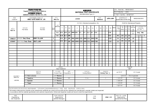
机械性能 Mechanical Property
屈服 YS (Mpa) 硬度 冲击试验Impact Test 延伸 收缩 Hardnes E R 冲击值 Akv, s (%) (%) 温度 Tem。℃: (HB)
Max Min 10562218 10358937 阀体原料/Body Blank 阀体半成品/Body Blank 8BSP3 V5,A105N 1BB1F,A105N
3 3
#### ##### 0.034 #### 0.018 #### 0.003 #### ##### 0.034 #### 0.018 #### 0.003
0.385 0.385
150 150
热处理 Heat Treatment
处理方法 Method 热处理批号 Batch No. 固溶/Solid solution 正火/Normalize 淬火/Quenched 回火/Temper 炉子类型 Furnace Type 电炉/Electric 电炉/Electric 电炉/Electric 电炉/Electric 920 空/Air 2 温度 Temperature(℃) 冷却方法 Cooling Method 保温时间 Holding Time(h) ■ 目测 VT
0.23 0.19 0.20 0.20
0.30 1.05 0.15 0.90 0.22 0.96 0.22 0.96
#### 0.03
0.1
0.4
0.12
0.4
0.05
0.43 0.35 485 585 585 250 379 379 22 43 43 30 66 66
137187
Avg: Min: 1 2 3
LX0192
化学成分 Chemical composition (%)
管道公称直径壁厚及压力对照表-304公称压力
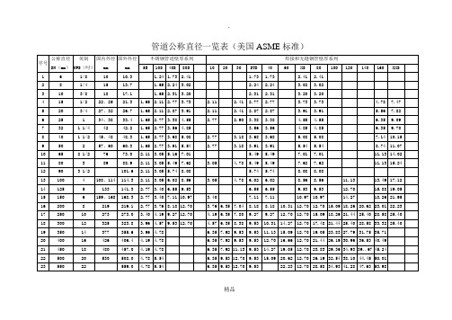
管道公称直径一览表(美国ASME标准)
精品
管道公称直径一览表(美国ASME标准)
精品
注:STD 指标准壁厚管 XS 加厚壁厚管 XXS 特别加厚壁厚管
S指不锈钢系列,不带S指其他钢种焊接和无缝钢管壁厚系列数据中系列加上Sch与没有Sch的意义相同如Sch5S与5S意义相同,Sch30与30意义相同
六角头螺栓螺纹规格 M10、 M12、 M14、 M16、 M18、 M20 、M22、 M24、 M27、M30 、M33、 M36、M39 、M42、 M45、M48、M52、 M56、M64、M72、 M76、M90
精品
管道公称直径一览表(SH3405-96)
精品
注:STD 指标准壁厚管 XS 加厚壁厚管 XXS 特别加厚壁厚管
S指不锈钢系列,不带S指其他钢种焊接和无缝钢管壁厚系列数据中系列加上Sch与没有Sch的意义相同如Sch5S与5S意义相同,Sch30与30意义相同SH3405-1996中规定不锈钢工程壁厚超过SCH 80S按碳钢此后规格的管道壁厚进行考虑
如有侵权请联系告知删除,感谢你们的配合!
精品。
swagelok不锈钢卡套管

不锈钢卡套管
英制尺寸
■ 标准仪表卡套管 ■ 化学清洗和钝化卡套管 ■ 热电偶清洗卡套管
特点
■ 可提供外径为 1/16 至 1 in. 的卡套管;如有需要还可 供应公制尺寸卡套管
标准仪表卡套管 材料标准
等级 316/316L
UNS S31603/S31603
➀ 公称壁厚,非最小壁厚。
公称长度 重量 m (ft) kg/m
0.01
0.01
0.04
0.05
0.12
0.16
0.19
0.19
6 (19.7)
0.25 0.32 0.26
0.35
0.45
0.55
0.45
0.58
0.56
0.71
1.2
化学清洗和钝化卡套管以及热电偶清洗卡套管 材料标准
等级
UNS
316L
S31603
➀ 公称壁厚,非最小壁厚。
卡套管 外径
in.
公称壁厚 in.
基本订购号 316L 无缝
公称长度 m (ft)
0.020 6L-T2-S-020-6M-
1/8
0.028
6L-T2-S-028-6M-G➀
0.035 6L-T4-S-035-6M1/4
0.049 6L-T4-S-049-6M-
0.035 6L-T6-S-035-6M3/8
最大 0.030
➀ 外径小于 1/2 in. 的卡套管可达 0.040 wt. % 的含碳量。
清洁和包装
化学清洗和钝化卡套管
这种卡套管在非挥发物质残余量方面符合 ASTM G93,A 级标准 的要求,也符合 CGA G4.1. 标准的要求。卡套管端部用聚酰胺尼 龙薄膜和聚乙烯帽盖来保护。卡套管单根包装在聚乙烯热封包装袋 中。
亚德客选型电子手册
标题:亚德客选型电子手册亚德客是全球知名专业生产各类气动器材的大型企业集团,致力于向客户提供满足其需求的气动控制元件、气动执行元件、气源处理元件、气动辅助元件等各类气动器材、服务和解决方案,为客户创造长期的价值和潜在的增长。
亚德客始创于1988年,现辖三大生产基地和一家营销中心,亚德客生产基地厂房面积达37万8千平方米,全球员工总计超过4500人,专业研发技术人员300多人,亚德客选型电子手册总投资1.5亿美元,年生产能力达5,000万件套,产品畅销中国、东南亚、欧美等国家和地区。
亚德客在中国大陆地区拥有近百家直销分公司/营业部,亚德客选型电子手册在全球更是有数千家经销商,主要位于欧洲、美洲及亚洲,形成了完善的销售网络和售后服务体系,可随时为客户提供便捷的服务。
亚德客以拓展集团生产和服务为未来发展的战略目标,坚持走人本优先、改革创新和集团化道路。
秉承“人本、共享、发展、责任”的企业核心价值观,亚德客始终如一地贯彻“以客为尊”的经营理念,始终如一地坚持“以技术创新为核心,亚德客选型电子手册以市场需求为导向”的经营方针,藉以不断完善“建立共好、责任承担、赏罚分明、学习成长”的集团文化,努力奋斗,自强不息,长久致力于全球工业自动化的持续发展。
台湾亚德客工业股份有限公司(简称台亚)成立于1988年11月,前身系健良股份有限公司,1990年更名为台亚。
早期的台亚主要生产电磁阀,此后亚德客选型电子手册陆续研发生产气缸、气源处理等产品。
目前,台亚产品以特殊规格气缸为主,拥有七大类十余系列数百个品种,年产量达到20万件套,主要供应台湾本地市场,满足客户需求及时效性。
1998年,台亚在同行中率先通过“ISO9000质量管理体系认证”;2004年,台亚取得“ISO14000环境体系认证”及“CE认证”。
长期以来,台亚秉持“质量第一、交货准时”的服务精神及理念满足客户需求,亚德客选型电子手册不断引进先进设备、生产工艺提升产品质量与品质。
美标Sch80 CPVC选型样本 2004

‡ Hi-Strength Schedule 80 CPVC Price List Effective March 26 , 2004• CPVC Pipe and Fittings• Sizes: ¼" to 12"GEORGE FISCHER ‡The technical information given in this publication implies no warranty of whatever kind and is subject to change without notice. Please consult our Terms and Conditions of Sale.Our modern facility in Little Rock, Ar-kansas, is the manufacturing center ofGeorge Fischer in the Americas. Withstate-of-the-art molding and extrusionmachines, as well as engineering andcustomer service, we provide the indus-trial piping system user with a diverserange of products and technical support.George Fischer products can be foundin a broad spectrum of industries, suchas chemical processing, semiconductor,pharmaceutical, food, photographic,environmental technology, marine, metalfinishing, water and waste water.Through strategically placed regionalwarehouses, a well-trained technicalsales force, and a network of stockingdistributors, George Fischer Sloane pro-vides viable solutions. George Fischer Sloane, Inc.George Fischer, Inc. is the sales facilityof George Fischer industrial products inthe Americas. The Tustin location offerscustomer and technical support, per-forms valve assembly, heat exchangerfabrication and distribution of GeorgeFischer valves and piping systems. AClass 10,000 clean room offers customfabrication of specialty components forthe ultrapure water market.George Fischer, Inc.Tustin, CaliforniaSignet Scientific is the engineering,manufacturing, and distribution facilityfor+GF+ SIGNET instrumentation.Signet Scientific CompanyEl Monte, California2¬ ‡3.piping.georgefiFor more information about any of our product lines, please call (800) 423-2686.Not for Use with Compressed Air or Gases Do Not Test with Air or Air Over WaterGeorge Fischer Sloane, Inc. DOES NOT RECOMMEND the use of thermoplastic piping products for sys-tems to transport or store compressed air or gases, or the testing of thermoplastic piping systems with com-pressed air or gases in above or below ground locations. The use of George Fischer Sloane, Inc. products in compressed air or gas systems automatically voids the warranty for such products, and their use against our recommendation is entirely the responsibility and liability of the installer. George Fischer Sloane, Inc. will not accept responsibility for damage or impairment from its products, or other consequential or incidental dam-ages caused by misapplication, incorrect assembly, and/or exposure to harmful substances or conditions.Table of ContentsCPVC Pipe ...................................................................................................................4Pressure Rating ...........................................................................................................4CPVC Fittings ¼” – 8” ...............................................................................................5Large Diameter CPVC Fittings 10” – 12” ..............................................................18General Terms and Conditions of Sale/Warranty .. (23)GlossarySTD Pack = Standard Carton FPT = Female Pipe Thread MPT = Male Pipe Thread MC = Master Carton S = Slip Socket SPG = Spigot End * = IAPMO (UPC Listed)Product line codes/descriptions Discount P/L 70 CPVC Pressure PipeP/L 25 CPVC Sch80 Pressure Fittings (molded ½" to 8")P/L 34 Fabricated Expansion Joints P/L 33 Brass Insert Fittings P/L 29 Alprene SaddlesP/L 02 CPVC Sch80 Large Diameter Fittings4¬ ‡Schedule CPVC Pressure Pipeinch size part number **pricinglift quantitylbs. per 100 ft.avg. o.D.min. wall psi at 73°F ½C8008-005AB*5600 ft.22.76.840.147848¾C8008-007AB*5000 ft.31.24 1.050.1546881C8008-010AB*4200 ft.46.23 1.315.1796301 ¼C8008-012AB*4000 ft.61.26 1.660.1915201 ½C8008-015AB*3600 ft.76.52 1.900.2004712C8008-020AB*2100 ft.104.60 2.375.2184042 ½C8008-025AB*1460 ft.156.55 2.875.2764253C8008-030AB*1160 ft.214.17 3.500.3003754C8008-040AB*1020 ft.301.49 4.500.3373246C8008-060AB*440 ft.597.86 6.625.4322798C8008-080AB 280 ft.928.288.625.50024610C8008-100AB 140 ft.1334.3010.750.59323012C8008-120AB100 ft.1834.4012.750.687230*IAPMO (UPC Listed)Pipe prices subject to change without notice.CPVC Pressure Pipe — 20 ft. LengthsP/L 70 Material: CPVC 23447-B Gray Meets ASTM F441Solvent-Welded Pressure Rating vs. Service Temperature — CPVC and PVCP73°F 90°F 100°F 110°F 120°F 130°F 140°F 160°F 180°F 200°F 210°F DPVC CPVC PVC PVC PVC PVC CPVC PVC CPVC PVC CPVC CPVC CPVC CPVC CPVC Nom.Outsidet DR=Df=1f=1f=0.75f=0.62f=0.50f=0.40f=0.65f=0.30f=0.57f=0.22f=0.50f=0.40f=0.25f=0.20f=0.16Size Dia.Wall t S=2000S=2000S=1500S=1240S=1000S=800S=1300S=600S=1135S=440S=1000S=800S=500S=400S=320½0.840.147 5.714848848636526424339552255484187424339212170136¾ 1.050.154 6.8186886885164263442754472063921513442751721381101 1.315.1797.3466306304733903152524101893591393152521581261011¼ 1.660.1918.691520520390322260208338156296114260208130104831½ 1.900.2009.50047147135329223518830614126810423518811894752 2.375.21810.8944044043032512021622631212308920216210181652½ 2.875.27610.4174254253192632121702761272429321217010685683 3.500.30011.667375375281233188150244113214831881509475604 4.500.33713.35332432424320116213021097185711621308165526 6.625.43215.336279279209173140112181841596114011270564588.625.50017.250246246185153123981607414054123986249391010.750.59318.128234234175145117931527013351117935847371212.750.68718.559228228171141114911486813050114915746361414.000.75018.6672261701401139168501616.000.84318.980222167138111896749P = 2St = 2S = P 73°F f D-t DR-1P = Pressure rating of pipe at service temperatures (psi)S = Hydrostatic design stress (psi)D =Outside diameter of pipe (inches)1) Figures for pressure rating at 73°F are rounded off from actual calculated values. Pressure ratings for other temperatures are calculated from 73°F values.2) Pressure rating values are for PVC (12454-B) and CPVC (23447-B) pipe and for most sizes are calculated from the experimentally determined long-term strength of PVC1 and CPVC extrusion compounds. Because molding compounds may differ in long-term strength and elevated temperature properties from pipe compounds, piping systems consisting of extruded pipe and molded fittings may have lower pressure ratings than those shown here, particularly at the higher temperatures. Caution should be exercised when designing PVC systems operating above 100°F and CPVC systems operating above 180°F.3) The pressure ratings given are for solvent-cemented systems. When adding valves, flanges or other components, the system must be derated to the rating of the lowest component. (Pressure ratings: molded or cut threads are rated at 50% of solvent-cemented systems; flanges and unions are 150 psi; for valves, see manufacturer’s recommendation.)t = Pipe wall thickness (inches)f = Derating factor for service temperature DR = Dimension ratio (D/t)P 73°F =Pressure rating at 73°F**For current pricing information please see separate price sheet or visit our website at.piping.georgefi5.piping.georgefi‡ Hi-Strength Schedule 80 CPVC Pressure FittingsP/L 25 Material: CPVC 23447-B GrayMeets ASTM F437 (Threaded) and F439 (Socket)Tee (S x S x S)inch size part number $ list std packlbs. eachHJ HN G ½9801-005*8.9425.13 1 25/64 1 25/6433/64¾9801-007*9.1115.19 1 37/64 1 37/6437/6419801-010*11.1620.29 1 53/64 1 53/6445/641 ¼9801-012*23.545.42 2 5/32 2 5/3229/321 ½9801-015*26.995.62 2 13/32 2 13/32 1 1/3229801-020*30.045.82 2 25/32 2 25/32 1 9/322 ½9801-025*76.465 1.73 3 9/32 3 9/32 1 17/3239801-030*76.465 2.56 3 23/32 3 23/32 1 55/6449801-040*101.765 3.89 4 19/32 4 19/32 2 23/6469801-060*264.77110.59 6 9/16 6 9/16 3 9/1689801-080758.47120.138 9/168 9/164 9/16Reducing Tee (S x S x S)inch size part number $ list std pack lbs. each HJ HN G¾ x ¾ x ½9801-10120.41150.18 1 5/8 1 5/81 x1 x ½9801-13023.51150.24 1 7/8 1 7/81 x1 x ¾9801-13123.51150.261 7/8 1 7/81¼ x 1¼ x 19801-16846.03152215/161½ 1½ x ½ 9801-209FB 48.07221½ x 1½ x ¾9801-21048.07150.482 2 1½ 1½ x 19801-21148.07100.522 7/16 2 7/162 x 2 x ½ 9801-247FB 55.56 2 1/8 2 1/82 x 2 x ¾9801-248FB 55.56 2 1/8 2 1/82 x 2 x 19801-24957.2710 2 ¼ 2 ¼ 1 5/162 x 2 x 1½9801-25157.27 2 13/16 2 13/16 1 5/163 x 3 x 29801-338116.845 3 3/16 3 3/164 x 4 x 29801-420147.685 4 1/8 4 1/84 x 4 x 39801-422147.685 4 1/84 1/86 x 6 x 29801-528FB 471.921 3 9/166 x 6 x 39801-530FB 471.921 3 9/166 x 6 x 49801-532408.281 5 3/8 5 3/8 2 3/88 x 8 x 69801-585749.5017 5/87 5/83 5/86¬ ‡90° Ell (S x S)inch size part number $ list std pack lbs. each HJ HN G ¼9806-0029.7350.0461/6461/6421/643/89806-0039.7350.06 1 9/64 1 9/6413/32½9806-005* 3.8125.10 1 25/64 1 25/6417/32¾9806-007* 4.8825.14 1 37/64 1 37/6419/3219806-010*7.7310.23 1 53/64 1 53/6423/321 ¼9806-012*16.7410.37 2 5/32 2 5/3229/321 ½9806-015*18.6810.44 2 13/32 2 13/32 1 1/3229806-020*22.585.70 2 25/32 2 25/32 1 9/322 ½9806-025*51.935 1.25 3 9/32 3 9/32 1 17/3239806-030*58.805 1.87 3 23/32 3 23/32 1 55/6449806-040*105.885 3.24 4 19/32 4 19/32 2 23/6469806-060*212.76111.00 6 9/16 6 9/16 3 9/1689806-080520.64115.738 9/168 9/164 9/1690° Ell (FPT x FPT)inch size part number $ list std pack lbs. each HJHN G¼9808-00210.2350.0459/643/89808-00310.2350.051½9808-005 5.9425.10 1 9/32¾9808-007 8.8920.13 1 3/819808-01012.4910.34 1 11/161 ¼9808-01224.0210.34 1 15/161 ½9808-01525.8710.40 2 1/1629808-02034.675.722 11/32Tee (FPT x FPT x FPT)inch size part number $ list std pack lbs. each HJ HN G ¼9805-00219.8950.0559/6459/6421/643/89805-00319.8950.071125/64½9805-00519.8925.14 1 9/32 1 9/3233/64¾9805-00728.6615.18 1 3/8 1 3/837/6419805-01030.8415.31 1 11/16 1 11/1645/641 ¼9805-01231.0410.45 1 15/16 1 15/1629/321 ½9805-01532.6010.56 2 1/16 21/161 1/3229805-02036.195.722 11/322 11/321 9/3290° Ell (S x FPT)inch size part number $ list std pack lbs. each HJ HN G ½9807-00510.1025.09 1 25/64 1 9/3217/32¾9807-00711.8425.14 1 37/64 1 3/819/3219807-01015.5210.211 27/321 11/1623/32.piping.georgefi 45° Ell (FPT x FPT)inch size partnumber$ list std pack lbs. each KJ KN J¼9819-00213.6050.0349/643/89819-00313.6050.0413/16½9819-00512.9225.10 1 1/64¾9819-00714.1820.14 1 7/3219819-01015.6025.23 1 21/641 ¼9819-01226.6415.33 1 27/641 ½9819-01526.6410.39 1 ½29819-02035.19 5.57 1 23/3245° Ell (S x S)inch size partnumber$ list std pack lbs. each KJ KN J½9817-005* 4.6725.11 1 9/649/32¾9817-007* 6.7620.15 1 11/3211/3219817-010*10.7325.22 1 15/6411/321 ¼9817-012*21.0715.35 1 21/3213/321 ½9817-015*21.6325.40 1 55/6431/6429817-020*24.275.69 2 5/3221/322 ½9817-025*49.595 1.08 2 15/3247/6439817-030*63.735 1.40 2 21/3225/3249817-040*87.485 2.56 3 9/321 1/3269817-060*269.5019.35 4 13/161 13/16 89817-080560.71111.11 6 1/62 1/16Coupling (S x S)inch size partnumber$ list std pack lbs. each L N¼9829-00210.3750.03 1 23/643/323/89829-00310.3750.04 1 5/81/8½9829-005* 4.0325.07 1 57/641/8¾9829-007* 5.6420.10 2 9/649/6419829-010*7.5925.16 2 25/649/641 ¼9829-012*11.3825.242 21/325/321 ½9829-015*14.3310.302 29/325/3229829-020*16.645.43 3 5/325/322 ½9829-025*37.035.813 ¾¼39829-030*40.265 1.234¼49829-040*52.765 2.12 4 ¾¼69829-060*124.212 6.97 6 5/165/1689829-080335.7026.918 5/165/16278¬‡Coupling (FPT x FPT)inch size part number $ list std pack lbs. each L N ¼9830-00213.0450.03 1 9/323/323/89830-00313.0450.04 1 21/641/8½9830-00510.7225.07 1 41/64¾9830-00717.3325.09 1 23/3219830-01019.6825.16 2 3/321 ½9830-01522.4210.26 2 7/3229830-02026.435.362 9/32Reducer Coupling (FPT x FPT)inch size part number $ list std pack lbs. each L N ½ x ¼9830-07218.2850n/a 1 7/167/64½ x 3/89830-07318.2850.06 1 29/647/64¾ x ½9830-10119.6025.09 1 21/321/81 x ½9830-13023.6425.14 1 53/647/641 x ¾9830-13123.6425.14 1 7/87/641 ½ x 19830-21146.0120.252 7/647/6422Reducer Coupling (S x S)inch size part number $ list std pack lbs. each L N ¾ x ½9829-101*10.57250.121/81 x ½9829-130*15.04250.16 2 1/81/81 x ¾9829-131*15.04250.152 ¼1/81 ½ x ½9829-209FB 34.9311 ½ x ¾9829-210FB 34.9311 ½ x 19829-211*34.20150.282 5/81/81 ½ x 1 ¼9829-212*34.20200.312 x ½ 9829-247FB 46.2012 x ¾9829-248FB 46.2012 x 1 9829-249FB 46.2012 x 1 ¼9829-250FB 46.2012 x 1 ½9829-251*45.2450.443 9/16 3 9/162 ½ x 1 ½9829-291FB 52.6010.443 x 29829-338*104.025 1.014 3/8¼4 x 29829-420FB 126.784 x 39829-422*124.105 1.659 1/8 2 1/166 x 49829-532279.398 x 69829-585488.5127.049 1/82 1/16.piping.georgefi Flush Style Reducer Bushing (Spg x S)inch size part number$ list std pack lbs. each L HL ½ x ¼9837-0728.4450.02 1 7/647/16½ x 3/89837-0738.4450.03¾ x ½9837-101* 4.3150.04 1 9/3213/32 1 x ½9837-130* 6.6750.07 1 13/32½1 x ¾9837-131* 6.6750.06 1 13/3213/32 1 ¼ x ½9837-166*17.7625.14 1 17/3221/32 1 ¼ x ¾9837-167*17.7625.12 1 17/3217/32 1 ¼ x 19837-168*17.7625.09 1 17/3213/32 1 ½ x ½9837-209*20.0625.19 1 21/3225/32 1 ½ x ¾9837-210*20.0625.17 1 21/3221/32 1 ½ x 19837-211*20.0625.14 1 21/3217/32 1 ½ x 1 ¼9837-212*20.0625.08 1 21/3213/32 2 x ½9837-247*25.9010.32 1 25/3229/32 2 x ¾9837-248*25.9025.30 1 25/3225/32 2 x 19837-249*25.9025.25 1 25/3221/32 2 x 1 ¼9837-250*25.9010.20 1 25/3217/32 2 x 1 ½9837-251*25.9010.17 1 25/3213/32 2 ½ x 1 ½9837-291*31.525.40 2 5/6441/64 2 ½ x 29837-292*31.525.27 2 3/3233/64 3 x 1 ½9837-33749.083 x 29837-338*48.065.61 2 7/3223/32 3 x 2 ½9837-339*48.065.38 2 13/6441/64 4 x 29837-420*53.125 1.14 2 45/641 9/64 4 x 39837-422*53.125 1.07 2 11/16¾6 x 49837-532113.182 3.622Male Adapter (S x MPT)inch size part number$ list std pack lbs. each L½9836-005 5.2250.04 1 13/16¾9836-007 6.3925.06 1 63/64 19836-01010.7025.10 2 11/32 1 ¼9836-01215.781515 2 ½1 ½9836-01521.3315.18 2 21/32 29836-02029.5639836-030108.3249836-040183.13Female Adapter (S x FPT)inch size part number$ list std pack lbs. each L HL¼9835-00213.1650.03 1 13/3247/64½9835-005* 6.5125.07 1 ¾13/16¾9835-007* 6.9020.10 1 59/6455/6419835-010*15.9225.16 2 15/641 3/641 ¼9835-012*16.3010.22 2 27/641 5/641 ½9835-015*18.9910.282 9/161 7/6429835-020*32.715.41 2 23/321 9/6439835-030*128.775 1.20 3 ¾ 1 49/6449835-040*214.325 1.92 4 15/641 55/642Extended Style Reducer Bushing (Spg x S)inch size part number$ list std pack lbs. each L HL½ x 3/89837-073E8.4450 .02 1 29/321 7/646 x 49837-532E113.18 23.50 6 7/84 5/81 2910¬ ‡Extended Style Reducer Bushing (Spg x FPT)inch size part number $ list std pack lbs. each L 3/8 x ¼9838-052E 9.0650.01 1 37/64½ x 3/89838-073E9.0650.021 23/32Extended Style Reducer Bushing (MPT x FPT)inch size part number $ list std pack lbs. each L ¾ x ½9839-101E 5.7750.02 1 49/641 x ¾9839-131E 9.7550.04 1 55/641 ¼ x 19839-168E 19.1725.07 2 17/641 ½ x 1 ¼9839-212E 23.0910.06 2 5/162 x 1 ½9839-251E23.0910.122 3/8Flush Style Reducer Bushing (Spg x FPT)inch size part number $ list std pack lbs. each L ½ x ¼9838-0729.0650.02 1 7/64½ x 3/89838-0739.0650.03¾ x ¼9838-09810.33¾ x ½9838-101* 4.7050.04 1 9/321 x ½9838-130* 5.9750.08 1 13/321 x ¾9838-131* 5.9750.06 1 13/321 ¼ x ½9838-166*19.2215.14 1 17/321 ¼ x ¾9838-167*19.2215.13 1 17/321 ¼ x 19838-168*19.2215.08 1 17/321 ½ x ½9838-209*23.6815.19 1 21/321 ½ x ¾9838-210*23.6815.18 1 21/321 ½ x 19838-211*23.6815.13 1 21/321 ½ x 1 ¼9838-212*23.6825.17 1 21/322 x ½9838-247*32.5410.20 1 25/322 x ¾9838-248*32.5410.33 1 25/322 x 19838-249*32.5410.30 1 25/322 x 1 ¼9838-250*32.5410.21 1 25/322 x 1 ½9838-251*32.5410.10 1 25/322 ½ x 1 ½9838-291*51.705.40 2 3/322 ½ x 29838-292*51.705.34 2 3/323 x 29838-338*115.265.62 2 7/324 x 29838-420*234.845 1.14 2 5/84 x 39838-422*234.8451.072 5/812Flush Style Reducer Bushing (MPT x FPT)inch size part number $ list ½ x ¼9839-07212.44¾ x 3/89839-09912.44¾ x ½9839-101 5.891 x ½9839-1309.941 x ¾9839-1319.941 ¼ x 19839-16819.581 ½ x 19839-21123.761 ½ x 1 ¼9839-21223.582 x 1 ½9839-25123.58Cap (S)inch size part number $ list std pack lbs. each W HL ½9847-005* 6.3050.05 1 9/3213/32¾9847-007*8.9625.07 1 29/6429/6419847-010*15.8425.12 1 21/3217/321 ¼9847-012*17.3315.16 1 55/6439/641 ½9847-015*17.3310.22 2 1/1611/1629847-020*18.285.37 2 19/6451/642 ½9847-025*61.525.60 2 23/3231/3239847-030*67.465.92 3 1/32 1 5/3249847-040*68.585 1.48 3 41/64 1 25/6469847-060*226.882 5.11 4 61/64 1 61/6489847-080688.522 6.72 6 ½2 ½Cap (FPT)inch size part number $ list std pack lbs. each W 3/89848-003 8.1350.0315/16½9848-005 6.9750.05 1 5/32¾9848-00711.5825.06 1 15/3219848-01016.1825.11 1 33/641 ¼9848-01228.8415.16 1 5/81 ½9848-01529.5810.22 1 11/1629848-02042.56 5.30 1 55/6445° Wye (S x S x S)inch size part number $ list std pack 1 ½9870-01539.31129870-020112.78139870-030362.61149870-040450.00169870-060613.3314 x 29870-420440.2216 x 49870-532467.561Flange (Blind)inch size part number $ list std pack lbs. each no. of holes bolt d.bolt circle d.M R L N ½9853-00526.025.294½ 2.38 3.5.41½¾9853-00728.215.384½ 2.75 3.88.479/1619853-01035.175.504½ 3.13 4.25.5311/161 ½9853-01554.515.674½ 3.885.6613/1629853-02057.285 1.0845/8 4.756.7115/1639853-03085.965 2.1345/867.5.89 1 1/849853-040145.895 3.6585/87.59 1.09 1 11/3269853-060249.961 4.38¾9.589853-080463.691 6.98¾11.75Flange (S)inch size part number $ list std pack lbs. each no. of holes bolt d.bolt circle d.M R L N ½9851-005*16.985.214½ 2.38 3.50.41 1 1/321/8¾9851-007*17.395.284½ 2.75 3.88.47 1 5/321/819851-010*18.995.394½ 3.13 4.25.53 1 9/321/81 ¼9851-012*23.165.504½ 3.50 4.62.60 1 7/161/81 ½9851-015*25.725.644½ 3.88 5.00.66 1 9/161/829851-020*31.135.9845/8 4.75 6.00.71 1 11/161/82 ½9851-025*64.505 1.5045/8 5.507.00.77 1 31/325/3239851-030*67.465 1.8845/8 6.007.50.89 2 3/325/3249851-040*91.135 3.0485/87.509.00 1.09 2 15/325/3269851-060*155.231 4.358¾9.5011.00 1.25 3 27/325/16Flange (FPT)inch size part number $ list std pack lbs. each no. of holes bolt d.bolt circle d.M R L N ½9852-00523.745.624½ 3.885.66 1 7/32¾9852-00728.8154½ 3.8819852-01031.445.394½ 3.13 4.25.53 1 1/81 ½9852-01546.195.624½ 3.885.66 1 7/3229852-02047.035.9545/8 4.756.71 1 ¼39852-03075.745 1.8745/867.5.89 1 27/3249852-040117.765 2.9185/87.59 1.09 1 15/16Plug (MPT)inch size part number $ list std pack lbs. each L R ¼9850-002 6.5350.0113/167/323/89850-003 6.5350.0153/647/32½9850-005 5.6850.0331/327/32¾9850-0077.2050.04 1 3/64¼19850-01011.8225.06 1 ¼17/641 ½9850-01514.8220.13 1 3/821/6429850-02020.1810.20 1 15/3213/3212Van Stone Flange (S)inch size part number $ list std pack lbs. each no. of holes bolt d.bolt circle d.M R L N ½9854-00517.115.244½ 2.38 3.5.56 1 1/83/16¾9854-00717.485.314½ 2.75 3.88.58 1 ¼3/1619854-01019.105.404½ 3.12 4.25.66 1 3/83/161 ¼9854-01223.325.524½ 3.5 4.62.69 1 ½3/161 ½9854-01525.905.664½ 3.885.75 1 11/16¼29854-02031.345 1.1845/8 4.756.94 1 7/8¼2 ½9854-02564.965 2.1345/8 5.57 1.12 2 1/85/1639854-03068.015 2.4945/867.5 1.31 2 3/83/849854-04091.865 3.4785/87.59 1.41 2 ¾7/1669854-060156.501 5.608¾9.511 1.62 3 9/167/1689854-080470.9118.058¾11.7513.5 1.91 4 9/16½109854-1001377.47114.26127/814.2516 2.12 5 5/8½129854-1202066.64123.22127/81719 2.31 6 11/169/16Van Stone Flange (FPT)inch size part number $ list std pack lbs. each no. of holes bolt d.bolt circle d.M R L N 19855-01031.675.444½ 3.12 4.25.66 1 3/87/161 ¼9855-01243.585.574½ 3.5 4.62.69 1 ½½1 ½9855-01546.515.694½ 3.885.75 1 11/165/829855-02047.375 1.1845/8 4.756.94 1 7/8¾Van Stone Flange (Spg)inch size part number $ list std pack lbs. each no. of holes bolt d.bolt circle d.M R L N ½9856-00519.795.24½ 2.38 3.5.56¾9856-00721.225.264½ 2.75 3.88.5819856-01024.115.454½ 3.12 4.25.66 2 1/87/81 ¼9856-01229.835.564½ 3.5 4.62.69 2 ¼11 ½9856-01533.005.714½ 3.885.75 2 ½ 1 1/1629856-02046.195 1.2845/8 4.756.94 2 13/16 1 ¼2 ½9856-02568.705 2.2445/8 5.57 1.1239856-03075.231 2.0545/867.5 1.3149856-04077.421 3.7985/87.59 1.41Nipple (MPT x MPT)inch size part number$ list std pack lbs. each L½ x CL9861-077* 2.7250.02 1 1/8½ x SH9861-015 2.4150.02 1 1/8½ x 29861-079* 5.1850.042½ x 39861-081 4.4750.063½ x 49861-082 4.4550.084½ x 59861-083 5.1850.095½ x 69861-084*9.4650.126¾ x CL9861-104* 4.8625.04 1 3/8¾ x 29861-020 3.4925.052¾ x 39861-106*10.1025.083¾ x 49861-107 5.6025.104¾ x 59861-108 6.6625.135¾ x 69861-109*20.3925.1561 x CL9861-133*7.7925.06 1 ½1 x SH9861-134*10.1025.0821 x 39861-135 6.1325.1231 x 49861-1368.3025.1541 x 59861-1379.2925.1951 x 69861-138*30.0125.2361 ¼ x CL9861-170 5.6025.08 1 5/8 1 ¼ x SH9861-171*14.0925.10 2 ½1 ¼ x 39861-1728.2425.1531 ¼ x 49861-17310.2425.2041 ¼ x 59861-17412.3625.2651 ¼ x 69861-17514.4825.3161 ½ x CL9861-213*15.0525.09 1 ¾1 ½ x SH9861-214*17.0625.132 ½1 ½ x 39861-2159.0925.1931 ½ x 49861-21618.8925.2541 ½ x 59861-21713.7325.3251 ½ x 69861-218*50.172562 x CL9861-251*22.7725.1422 x SH9861-252*28.2225.18 2 ½2 x 39861-253*33.5025.2632 x 49861-25415.6825.3542 x 59861-25518.8025.4452 x 69861-256*50.2125.5262 ½ x CL9861-00517.115.33 2 ½2 ½ x SH9861-03017.225.3932 ½ x 49861-04024.405.5242 ½ x 59861-05029.275.6552 ½ x 69861-06034.765.7863 x CL9861-33824.095.47 2 5/8 3 x SH9861-33924.515.5433 x 49861-34130.005.7143 x 59861-34237.405.8953 x 69861-34344.475 1.0764 x CL9861-42233.815.72 2 7/8 4 x SH9861-43343.525 1.0044 x 59861-42553.135 1.2654 x 69861-42663.595 1.51622Union W/ O-Ring (FPT x FPT)O-Ring Material: FPM inch size part number $ list std pack lbs. each L N 3/89858-00329.2625.10 1 57/6439/64½9858-00518.5625.23 2 13/3225/64¾9858-00732.785.30 2 9/1621/3219858-01045.205.44 2 31/329/161 ¼9858-01286.115.60 3 1/85/81 ½9858-01586.115.69 3 19/3219/3229858-02097.342.97 3 ¾43/6439858-030308.372 2.89 4 17/3229/3249858-040326.671 4 8/16inch size part number $ list std pack lbs. each L N ¼9857-00226.0325.08 1 55/6439/643/89857-00326.0325.12 1 57/6425/64½9857-00517.3025.22 2 13/3221/32¾9857-00718.105.30 2 9/169/1619857-01021.705.42 2 31/3223/321 ¼9857-01243.925.64 3 1/85/81 ½9857-01544.735.75 3 7/1619/3229857-02074.142 1.04 3 43/6443/6439857-030153.872 2.89 4 17/3229/3249857-040200.811 5 9/16 2 ¼Union W/ O-Ring (S x S)O-Ring Material: FPM Union W/ O-Ring (FPT x FPT)O-Ring Material: EPDM inch size part number $ list std pack lbs. each L N 3/89898-00328.9025.10 1 57/64½9898-00518.3225.23 2 13/32¾9898-00732.375.30 2 1/819898-01044.635.44 2 31/321 ¼9898-01285.045.60 3 1/81 ½9898-01585.045.69 3 19/3229898-02096.142.97 3 ¾39898-030304.601 2.89 4 17/3249898-040320.501 4 8/16Union W/ O-Ring (S x S)O-Ring Material: EPDM inch size part number $ list std pack lbs. each L N ¼9897-00225.7125.08 1 55/6439/643/89897-00325.7125.12 1 57/6425/64½9897-005*17.2625.22 2 13/3221/32¾9897-007*17.885.30 2 9/169/1619897-010*21.405.42 2 31/3223/321 ¼9897-012*43.375.64 3 1/85/81 ½9897-015*44.195.75 3 7/1619/3229897-020*73.222 1.04 3 43/6443/6439897-030*151.981 2.89 4 17/3229/3249897-040198.531 5 9/162 ¼22Fabricated Expansion Joint - 6" Travel Inch Size EPDM $ list FPM $ list ½9826-005X6191.259836-005X6225.00¾9826-007X6210.009836-007X6246.2019826-010X6226.209836-010X6266.151 ¼9826-012X6259.009836-012X6304.701 ½9826--015X6328.109836-015X6386.0529826-020X6345.109836-020X6406.0039829-030X6452.359836-030X6532.2049826-040X6717.159836-040X6843.7369826-060X6784.959836-060X6923.49Note: Other end connections available, please consult factory.Fabricated Expansion Joint - 12" Travel Inch Size EPDM $ list FPM $ list ½9826-005X12194.759836-005X12229.15¾9826-007X12223.359836-007X12262.8019826-010X12238.309836-010X12280.351 ¼9826-012X12299.109836-012X12351.901 ½9826-015X12377.759836-015X12444.4029826-020X12381.809836-020X12449.1539826-030X12464.509836-030X12546.5049826-040X12769.459836-040X12905.2569826-060X12847.659836-060X12997.25Note: Other end connections available, please consult factory.90° Ell (S x FPT Brass)Inch Size Part Number $ list I L1Z1Z2½ x ½812010080620.25 1 2/16 1 7/169/169/16¾ x ½812010083725.35 1 3/16 1 5/810/1610/16Tee (S x S x FPT Brass)Inch Size Part Number $ list I L1Z1Z2½ x ½ x ½812020080623.00 1 1/8 1 7/169/169/16¾ x ½ x ½812020083728.55 1 3/16 1 5/810/165/8Coupling (S x FPT Brass)Inch Size Part Number $ list I Z ½ x ½812091080612.50 1 11/16 1 1/8¾ x ½812091083718.10 1 13/16 1 ¼Male Adapter (S x MPT Brass)Inch Size Part Number $ list I Z ½812090080612.50 1 11/1615/16¾812090080725.85 1 7/815/161812090080845.35 2 1/161Expansion Joint P/L 34Brass Insert Fittings P/L 33。
常见镀锌管及PVC塑料管规格表
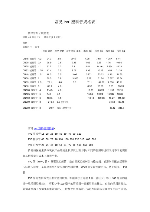
常见PVC塑料管规格表镀锌管尺寸规格表焊管(6 米定尺)镀锌管(6米定尺)规格公称内径英寸外径mm 壁厚mm 最小壁厚mm 米重kg 根重kg 米重kg 根重kgDN15 镀锌管1/2 21.3 2.8 2.45 1.28 7.68 1.357 8.14DN20 镀锌管3/4 26.9 2.8 2.45 1.66 9.96 1.76 10.56DN25 镀锌管 1 33.7 3.2 2.8 2.41 14.46 2.554 15.32DN32 镀锌管 1.25 42.4 3.5 3.06 3.36 20.16 3.56 21.36DN40 镀锌管 1.5 48.3 3.5 3.06 3.87 23.22 4.10 24.60DN50 镀锌管 2 60.3 3.8 3.325 5.29 31.74 5.607 33.64DN65 镀锌管 2.5 76.1 4.0 3.5 7.11 42.66 7.536 45.21DN80 镀锌管 3 88.9 4.0 8.38 50.28 8.88 53.28 DN100 镀锌管 4 114.3 4.0 10.88 65.28 11.53 69.18 DN125 镀锌管 5 140 4.5 15.04 90.24 15.942 98.65 DN150 镀锌管 6 168.3 4.5 18.18 109.08 19.27 115.62 DN200 镀锌管8 219.1 6.0(焊管) 31.53 189.18DN200 镀锌管8 219.1 6.5(热镀锌) 36.12 216.7常见pvc塑料管规格表:PVC穿线管 16 20 25 30 40 50 75 90 110PVC排水管 40 50 75 90 110 160 200 250 315 400 500PVC给水管 20 25 32 40 50 63 75 90 110 160 200价格的区别主要体现在产品的质量和厚度上面,同时不同的使用环境应采用不同的规格在工程质量与成本上取得平衡。
管工培训材料

答: 五种: 1. 承插连接 2.法兰连接 3. 螺纹连接 4.焊接连接 5.胀管 连接
9.气割工作原理是什么?
答: 气割是利用可燃气体(如乙炔) 与氧气混合燃烧的予热火焰 ,将 金属加热到燃烧点(约1100℃~1150 ℃ ) 使金属在高压氧气射流 中剧烈燃烧 , 而将金属分开的加工方法。
6.0 对有毒、可燃、腐蚀性物料的设备、容器、管道检查 维修前的处理
应按规定的时间进行彻底的蒸气吹扫 , 热水蒸煮 , 酸碱中和 ,氮 气置换 , 使其内部不含残液 , 余气 , 取样分析达到技术要求 , 并用 盲板与相关的设备管理管道系统隔绝。
YPMC
● ● ●
第五章 管工达标考核复习题
1. 化工管道按管道在生产中功用分类
1.55 掌握起重指挥术语及手势 ,学会各种吊索的荷重计算选用标准。
1.56 管道的绝热计算及绝热材料的选用。
1.57 掌握各种复杂难度管件的下料展开画法及壁厚处理
1.58 复杂管线的剖视图 ,轴测图。
1.59 装置内部设备管线的全系统的吹扫施压方法及施工
C
2.实际操作技能(应会)
2. 1 工艺热力外管的现场消缺。 2.2 上水 ,采暖工程的施工检修及安装工艺。 2.3 工艺热力管道系统检修与安装。 2.4 各种管道的支架 ,管卡的制作与安装。
YPMC
第二课 现代化管理基础知识与技能
1.0 全面质量管理是企业管理的中心环节
企业管理作为一个系统 ,是由多项专业管理工作组成的有机整体,
格种专业管理在企业管理中占有不同的地位 ,发挥着不同的作用,但由 于产品质量的重要性(质量是企业的生命 , 品种是企业的前途 ,产品 质量低劣企业是无生存能力的) 。综合性(产品质量是企业各项工作 好坏的综合反映 ,提高质量是企业各部门 ,各环节共同努力的结果)
SMC气动技术培训教材

水:-20~40 ℃
TUS
极软聚氨脂
4
0.5
空气
-20~40
0.4MPa
40~60 ℃
TUH
硬聚氨脂
18
0.8
空气
-20~60
高压型:1.0MPa
TUZ
特殊聚氨脂
15
0.8
空气
-20~60
耐磨型
60℃:0.4MPa
2021/7/4
41
系列
材质
弯曲性
最高使用压力()
使用流体
(Φ6管)
难燃软尼龙
17
使用温度
螺纹,气管ø5/32", ø1/4", ø5/16", ø3/8", ø1/2"
30
特列环境用快速接头
耐腐蚀环境用快换接头
可使用在真空系统上。
金属部分采用不锈钢(303),代替传统的黄铜。
适合作以下用途:
食品加工机械设备,可能接触洗涤水或盐水的地方。
无铜设备用,例如显像管生产线上等。
洁净房
白色主体易于辨别。
流体:空气,水
:
1/ 8 “ 3 /16" 1 /4 “ 3/ 8" 1 /2"
100mリール巻 【ø16を除くミリサイズ・インチサイズ対応】型式表示の末尾に-X3を付加します。例)T0425R-100-X3
長尺リール巻 【ミリサイズ対応】型式表示の末尾に-X3を付加します。例)T0425G-500-X3
2021/7/4
23
系列
单向阀的耦合接头
带
系列
带单向阀的耦合接头(带吸收冲击罩)
2021/7/4
24
气动元件培训资料
气动元件培训资料通过气体的压强或膨胀产生的力来做功的元件,即将压缩空气的弹性能量转换为动能的机件。
如气缸、气动马达、蒸汽机等。
它是一种动力传动形式,亦为能量转换装置,利用气体压力来传递能量。
一、气动元件的优点:1、气动装置结构简单、轻便、安装维护简单。
介质为空气,较之液压介质来说不易燃烧,故使用安全。
2、工作介质是取之不尽的空气、空气本身不花钱。
排气处理简单,不污染环境,成本低。
3、输出力以及工作速度的调节非常容易。
气缸的动作速度一般小于1M/S,比液压和电气方式的动作速度快。
4、可靠性高,使用寿命长。
电器元件的有效动作次数约为百万次,而一般电磁阀的寿命大于3000万次,某些质量好的阀超过2亿次。
5、利用空气的压缩性,可贮存能量,实现集中供气。
可短时间释放能量,以获得间歇运动中的高速响应。
可实现缓冲。
对冲击负载和过负载有较强的适应能力。
在一定条件下,可使气动装置有自保持能力。
6、全气动控制具有防火、防爆、防潮的能力。
与液压方式相比,气动方式可在高温场合使用。
7、由于空气流动损失小,压缩空气可集中供应,远距离输送。
二、气动元件的缺点:1、由于空气有压缩性,气缸的动作速度易受负载的变化而变化。
采用气液联动方式可以克服这一缺陷。
2、气缸在低速运动时候,由于摩擦力占推力的比例较大,气缸的低速稳定性不如液压缸。
3、虽然在许多应用场合,气缸的输出力能满足工作要求,但其输出力比液压缸小。
气动技术是以压缩空气为介质来传动和控制机械的一门专业技术。
由于它具有节能、无污染、高效、低成本、安全可靠、结构简单等优点,广泛应用于各种机械和生产线上。
过去汽车、拖拉机等生产线上的气动系统及其元件,都由各厂自行设计、制造和维修。
三、我国气动元件的发展气动技术应用面的扩大是气动工业发展的标志。
气动元件的应用主要为两个方面:维修和配套。
过去国产气动元件的销售要用于维修,近几年,直接为主要配套的销售份额逐年增加。
国产气动元件的应用,从价值数千万元的冶金设备到只有广2百元的椅子。
蒸汽管道组件E28目录4100-5 UK1 2 4 3 L1 O-Lok装配说明书
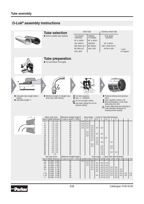
O-Lok® assembly instructionsMinimum length of straight tube-Cut tube squarelyL1E1040Parflange ® 1025132586497O-Lok ® machine flanging and assembly●Preferred and●Most efficient method ●Parflange ® recommendedParflange ® machines:●Select flaring pin according to tube dimensions●Use special “SS“ pin for stainless steel tube●Pin must be clean and free of wear, damage and metal particles●Keep flaring pin clean and lubricate regularly●Select flanging dies according to tube dimensions●Use special “SS“ dies for stainless steel tube to avoid contact corrosion●Grip surface must be clean and free of wear●Use only genuine Parker tooling for flanging O-Lok ®●Load pin into machine●Ensure lubricating system is filled with oil (1040LUBSS)●Place sleeve in lower die half ●Locate upper die half onto lower half●Place the dies in the die housing●Slide nut onto tube before flanging!●Open threads towards machine●Pull down the handle to clamp the tube in the dies (1025)●1040 die clamping automatic in cycle●Press button to start flanging cycleƽKeep hands clear off the workingareaO-Lok ® assembly instructions●Parflange ® 1025:Unclamp the dies●Remove tube from machine ●Use die separator to free tube ●Parflange ® 1040:Die unclamping is automaticƽPress tube firmly into the dieagainst the tube stopminmaxØØ D2αO-Lok ® assembly instructionsE321O-Lok ® Montageanleitung assembly instructionsO-Lok ®: Replacement of O-ring●Parker CORG assembly tool should be used for O-Lok ® fitting with captive O-Ring groove (O-Lok ®)●Insert the O-ring into the slot located on the side of the tool●Position the open end of the tool over the tube-end of the fitting●Push the piston of the tool until the O-ring is released into the fitting groove●Function of Parker CORG assembly toolO-ringAssembly T ool。
