Allegro_PCB_Designer_datasheet
Allegro16.3—PCB设计笔记详解
Allegro16.3—PCB设计笔记详解打开PCB Editor。
一般选择第一项操作选择显示内容View——Customize Toolbar可以设置软件的菜单栏显示模块Commands是可以自定义工具查看各种层Display——Color/Visibility封装的制作在Pad Designer中操作此项首先制作贴片式焊盘的做法Candence制作封装需要先制作焊盘打开制作焊盘的软件开始>程序>candence>release 16.3>PCB Editer Utilities>Pad Designer表贴焊盘就不用填写Themal Relief(散热焊盘)和Anti Pad(绝缘层焊盘)了这是建立好的焊盘文件然后打开PCB Editor——File——New——设置图纸大小Setup——Design Parameter Editor——Design User Unist(单位)选择Extents项中Left X和Lower Y为原点的坐标定义,Width和Heigh 为做封装时图纸的大小>Type项不变,仍为Package(封装)。
都改为0.0254(最小步进值)开始加入焊盘>Layout>Pin>>Option中如下设置创建一个零件库必须的几个条件:1至少一个引脚。
2每个零件必须有图形边框,即轮廓线,线路板上丝印层白漆所画的轮廓。
3参考编号。
4要有Place_bound,即安装区,防止元器件之间的叠加。
做通孔类焊盘的时候要求焊盘过孔镀锡后要比元件引脚直径大0.2或0.3毫米最好。
这样有利于波峰焊是焊锡往上走。
同时也利于排气。
如果孔太小,气体跑不出来,会夹杂在焊锡里,孔太大,元件会发生偏斜。
元件孔包括镀层(铜色的约0.1毫米),镀锡1)首先添加Assembly_T op2)然后设置丝印层边框3)放置Add——Rectangle4)放置参考编号Layout——Labels Ref Des继续放置丝印层,并且放在第一个引脚的边上。
Allegro_PCB_SI_L_XL
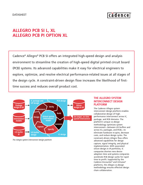
DATASHEETALLEGRO PCB SI L, XLALLEGRO PCB PI OPTION XLCadence®Allegro®PCB SI offers an integrated high-speed design and analysis environment to streamline the creation of high-speed digital printed circuit board (PCB) systems. Its advanced capabilities make it easy for electrical engineers to explore, optimize, and resolve electrical performance-related issues at all stages of the design cycle. A constraint-driven design flow increases the likelihood of first-time success and reduces overall product cost.THE ALLEGRO SYSTEM Array INTERCONNECT DESIGNPLATFORMThe Cadence Allegro systeminterconnect design platform enablescollaborative design of high-performance interconnect across IC,package, and PCB domains. Theplatform’s unique co-designmethodology optimizes systeminterconnect—between I/O buffers andacross ICs, packages, and PCBs—toeliminate hardware re-spins, decreasecosts, and reduce design cycles. Theconstraint-driven Allegro flow offersadvanced capabilities for designcapture, signal integrity, and physicalimplementation. With associatedsilicon design-in IP portfolios, ICcompanies shorten new deviceadoption time and systems companiesaccelerate PCB design cycles for rapidtime to profit. Supported by theCadence Encounter®and Virtuoso®platforms, the Allegro co-designmethodology ensures effective designchain collaboration.ALLEGRO PCB SIAllegro PCB SI provides advanced analysis at the board, multi-board,and/or system level, and across multiple design configurations. It supports the entire high-speed design flow, which includes pre-layout exploration of design parameters such as differential impedance, development of physical parameters, and imprinting of constraints within the PCB database. The result is a true, constraint-driven design flow. Allegro PCB SI integrates tightly with Allegro PCB Editor, Allegro PCB Router, and Allegro Design Entry HDL enabling end-to-end, constraint-driven, high-speed PCB system design.Allegro PCB SI addresses the challenges created as a result of increasing design density, complexity, and faster edge rates by enabling designers to address high-speed issues throughout the design process. This approach allows design teams to eliminate time-consuming simulate-fix-simulate iterations at the back-end of a design. It also enables designers to maximize electrical performance while minimizing cost of the overall product by exploring topologies and models with manufacturing tolerances. Allegro PCB SI allows users to weigh the tradeoffs involved in routing choices (rules) that affect cost relativeto electrical performance andreliability. Once developed, theseoptimal constraints then drive thephysical layout and routing of the PCB.The integrated design and analysisenvironment eliminates the need totranslate design databases to runsimulations. Designers can also addressshrinking timing margins byconsidering the effects of packagedesign on the overall performance ofthe signal from die-to-die. Importantly,the integrated flow allows designersto easily perform post-layoutextraction and verification of complexhigh-speed PCB systems.BENEFITS•Cuts the time required to design high-speed interconnects and increases thelikelihood of first-pass success•Shortens the time required to developoptimum constraints and enables aconstraint-driven PCB design flow•Shortens the time required to design-in advanced devices through the useof Cadence design-in IP portfolios•Improves product performancethrough solution space exploration•Reduces unit costs of end products byusing the Allegro PCB PI Option XL todesign the PCB power delivery systemnetworkFEATURESINTEGRATED HIGH-SPEED DESIGN ANDANALYSISAllegro PCB SI reads and writes to theAllegro PCB Editor database to avoidpossible translation issues and allowsfor constraints and models to beembedded in the board design file.The integrated design and analysissystem is aware of multi-net electricalconstructs from front to back. Forexample, differential pairs andextended nets (nets with a seriestermination) are recognized,extracted, and simulated as oneelectrical net.SOLUTION SPACE EXPLORATIONAllegro PCB SI provides the bestenvironment for users who need todevelop optimal constraints.SigXplorer, a graphical editor thatallows designers to develop constraintsthrough solution space exploration, isthe industry leader in pre-routeanalysis. Solve issues early in thedesign process by using sweptparameter analysis, user-definedstimulus, and custom measurements.SPICE-BASED SIMULATORThe Allegro PCB SI simulationsubsystem includes a SPICE-basedsimulator as well as a powerful macro-modeling capability that combines theadvantages of traditional SPICE-basedstructural modeling with the speed ofbehavioral modeling. An embeddedfield solver models skin effects,proximity/crowding effects, returnpath resistance, and frequency-dependent dielectric constant. Arobust modeling language providesextensibility beyond IBIS for I/O buffersand lossy coupled, frequency-dependent transmission line modelsthat accurately predict the distributedbehavior of PCB traces.BUS ANALYSIS FOR SOURCESYNCHRONOUS SIGNALSAllegro PCB SI provides a quick andeasy way to analyze all the signalsassociated with a source synchronousbus. It shortens the time to simulatevarious configurations (read/write,active, idle) associated with thefunctioning of source synchronousbuses with or without on-dietermination (ODT). It allows signalsto be associated and to save suchassociations with the design database.Allegro PCB SI allows engineers to explore and develop optimum constraints with a constraint-driven design flow23DIE-TO-DIE INTERCONNECT ANALYSIS USING PACKAGE DATABASES Allegro PCB SI supports multi-board configurations for both analysis and constraints, and provides a simple setup process—from motherboard or daughter card connection to a die-to-die configuration. It also supports topology exploration, floorplanning,and post-route verification. CONSTRAINT-DRIVEN PROCESS Allegro Constraint Manager functions within Allegro PCB SI, Allegro Design Entry HDL, and with Allegro PCB Design XL, allowing designers to use constraints developed through solution space exploration to create a constraint-driven physical layout process.MODEL INTEGRITYThe Model Integrity module allows designers to create, manipulate, and validate models quickly in an easy-to-use editing environment. Device model formats supported include:•IBIS 4.1 External Model support for Verilog ®-A, Cadence Spectre ®, HSPICE,Cadence eSpice models •Mentor/Quad XTK•Cadence Device Modeling Language (DML)A Spectre-to-DML conversion module assists in creating DML models from Spectre simulation runs. With the output of the Spectre simulation run,buffer options file, users can quickly create DML models. Model integrity identifies V-I and V-T tables for typical,maximum, and minimum corner casesfrom the Spectre run file. A proven,intelligent best-curve-fitting algorithm provides an accurate DML model. An HSPICE–to-IBIS conversion moduleallows users to create IBIS models from HSPICE simulation runs.I/O BUFFER MODELSSupported I/O buffer model formats include:•Cadence Allegro PCB SI DML•Synopsys HSPICE transistor-levelmodels (requires HSPICE simulator and license, which is not included with Allegro PCB SI)•Spectre transistor-level models(available on Sun Solaris, HP UX, and Linux RHEL 3.0 platforms only). This utilizes an integrated and limited capability version of the Spectre simulator, which is included with Allegro PCB SI XL•IBIS 4.1 External Model support for HSPICE, Spectre, Verilog-A and Cadence DML •Mentor/Quad XTKMENTOR BOARD STATION FLOW Allegro PCB SI can be used inconjunction with the Mentor Board Station PCB design system to provide high-speed design and analysis within a Mentor-based PCB designenvironment. Allegro PCB SI is used to perform high-speed analysis and to define the high-speed design rules used to drive the Allegro PCB Router.Once the design has been placed and routed in accordance with the high-speed rules, the results are passed back to the Mentor Board Station environment. This allows Allegro PCB SI and the Allegro PCB Router to beAllegro PCB SI allows engineers to explore and develop optimum constraints with a constraint-driven design flowDe s ign implementationS olution s pa c e explorationMo d el d evelopment an d verifi c ation Con s traint-d riven pla c e an d routePo s t-layout verifi c ationCon s traint-d riven FPS pe c ifi c ation s Logi c an d timing d e s ignOptimal c on s traint sCon s traint- d riven phy s i c al implementationused for high-speed design and analysis, while the existing Board Station-based manufacturing output process is used for committing the design to manufacturing.DESIGN-IN IP PORTFOLIOA high-speed design-in IP portfolio shortens design-in time for complex devices with high-speed digital I/O buffers. Cadence pioneered this concept by introducing an IP portfolio for Intel’s 64-bit architecture and today stands as the industry leader in offering this kind of complete solution. Design-in IP portfolio contains ready-to-simulate topologies with pre-validated models, layout constraints embedded in a sample PCB file to enable constraint-driven layout flows, tutorials, documentation, scripts, and other utilities. A high-speed design-in IP portfolio includes prepackaged, executable specifications for complex IC devices with high-speed I/Os. Cadence collaborates with IC companies to make it easy for systems companies to design-in complex IC devices with high-speed I/Os.PCI EXPRESS DESIGN CHAINAs multi-gigahertz serial interfaces become more common, many systems companies are choosing to use the next-generation PCI bus—PCI Express. The PCI Express design chain provides an environment in which silicon vendors can communicate the design-in requirements for their devices using PCI Express. Systems companies are able to make tradeoffs regarding the performance of member companies’silicon with respect to system requirements.The PCI Express design chain is web-based infrastructure that enables systems companies that design serial links implementing the PCI Express specification to efficiently qualify member companies as candidates for their systems. For more information about other design-in IP portfolios and the PCI Express design chain, visit .INTEL IXP2800 NETWORK PROCESSORDESIGN-IN IP PORTFOLIOIntel and Cadence engineers workedtogether to provide a high-speeddesign-in IP portfolio for Intel’sIXP2800 network processor. Availablefrom Intel and included in thehardware design kit for IXP2800, thedesign-in IP portfolio contains ready-to-simulate system-level topologies forthe buses that interact with thenetwork processor (RDRAM, SPI4.2, PCI,and QDR); correlated silicon models; afully coupled frequency-dependentlossy package; and PCB trace, via, andconnector models to fully simulate andevaluate the signal quality anddegradation issues inherent in designswith high-speed nets. In addition, thedesign-in IP portfolio contains areference board that includes theconstraints for the main buses on theprocessor. This reference board and theconstraint sets can be used to drivefloorplanning, placement, and routingon the target PCB system that uses theIXP2800 networking processor. Theready-to-simulate topologies comewith instructions on how to use thesetopologies, as well as movies that showhow to use the design-in IP portfoliowith Allegro PCB SI. For moreinformation, contact your Intelrepresentative and ask for thehardware design kit (HDK) for theIXP2800 network processor.XILINX VIRTEX II-PRO DESIGN-IN IPPORTFOLIOXilinx and Cadence engineers workedtogether to provide a high-speeddesign-in IP portfolio in Allegro PCB SIformat for multi-gigabit serial RocketI/O transceivers integrated in XilinxVirtex II-Pro FPGAs. The Allegro PCB SIdesign-in IP portfolio helps engineersshorten design cycles and reducesignal integrity problems whenimplementing multi-gigabit serialtransceivers in PCB systems. It containscorrelated silicon models, preconfiguredtopologies ready to simulate, and afully coupled, frequency-dependentlossy package. It also contains PCBtrace, via, and connector models tofully simulate and evaluate the signalquality and degradation issuesinherent in designs with multi-gigabittransceivers. For more information,visit or contact yourXilinx or Cadence representative.POWER DELIVERY SYSTEMDESIGN WITH ALLEGRO PCBPI OPTION XLAllegro PCB PI Option XL module, anadd-on to Allegro PCB SI, is a unique,integrated design and analysisenvironment that takes the guessworkout of quantifying and controllingnoise in power delivery systems. Itallows users to focus on the designinstead of struggling with datatranslation issues between the CADsystem and the analysis engines. Itintegrates proven technology fromSun Microsystems into the Cadencedesign and analysis environment toaddress the power delivery issuesencountered in high-speed design.Allegro PCB PI Option XL embodies amethodology used to design andoptimize frequency-dependentcharacteristics (supply pathimpedance) of power distributionsystems in high-speed PCB design. Itallows users to do quick and easyiterations of “change-simulate-analyze.” The Cadence approach isrooted in the fact that a powerdistribution system’s impedance isfrequency dependent and must beanalyzed and controlled overfrequency ranges of interest. Themaximum supply current and thetolerated voltage ripple are used toderive the main power deliverysystem’s design parameter—the targetimpedance. Optimizing the targetimpedance over the frequency rangein which the system is expected tooperate yields a power delivery systemwithout hot spots.FEATURESSETUP WIZARDThe Setup Wizard gathers all thenecessary pieces for design andanalysis including board outline; layerstack-up; power plane shapes/powerand ground plane pairs; DC netsassociated with the power planes; andcapacitor libraries.4FREQUENCY DOMAIN ANALYSISAllegro PCB PI Option XL combines the right frequency domain analysis engine with the proven, powerful Allegro PCB SI and Allegro PCB Editor design environments. It simulates the problem in the frequency domain to quantify the impedance of the power delivery system across the frequency range of interest. During simulation, it takes into account the entire power delivery system—VRM, bulk capacitors, bypass capacitors, and power planes. It calculates the number and values of decoupling capacitors and guides users in placing them for optimal results. Users can perform single node analysis early in the design cycle to see if the number of capacitors selected can maintain the target impedance over a desired frequency range. And, as capacitors are placed on the board, multi-node simulation, which takes into account the location of the capacitors on the board and the mounted loop inductance, can be easily run.VRM EDITORThe VRM Editor comes with an easy-to-use input inductance calculator and a target impedance calculator. Specify the allowed voltage ripple and dynamic current to compute the target impedance, and the target impedance is shown in the simulation results waveform window. Thesimulation waveform window displaysa target impedance line, which makesit easy to know which regions of thePCB are crossing the target.VOLTAGE RIPPLES IN TIME DOMAINEffectiveness of decoupling capacitorselection and placement can beverified in time domain.COMPLETE DESIGN AND ANALYSISENVIRONMENTAllegro PCB PI Option XL offers aunique approach to the actualdesigning of power distributionsystems. It takes the integratedapproach a step further by making thedebugging of a problem as simple as“click and view.” Clicking on awaveform in the waveform displaywindow highlights the correspondingregion on the PCB and offers asuggestion on the type and number ofcapacitors needed to address theproblem. Results are displayed in thewaveform window. By having a PCBdesign editor integrated with thisanalysis environment, engineers canselect and place decoupling capacitorsin the necessary areas, and thenquickly see the problem resolved.OPERATING SYSTEMSUPPORT•Red Hat Linux 3.0, 4.0•Windows 2000 with Service Pack 4,XP Professional•Sun Solaris 8, 9, 10•HP-UX 11.11i•IBM AIX 5.3CADENCE SERVICES ANDSUPPORT•Cadence application engineers cananswer your technical questions bytelephone, email, or Internet—theycan also provide technical assistanceand custom training•Cadence certified instructors teachover 70 courses and bring their real-world experience into the classroom•Over 25 Internet Learning Series (iLS)online courses allow you the flexibilityof training at your own computer viathe Internet•SourceLink®online customer supportgives you answers to your technicalquestions—24 hours a day, 7 days aweek—including the latest in quarterlysoftware rollups, product changerelease information, technicaldocumentation, solutions, softwareupdates, and moreDESIGN-IN IP PORTFOLIOS ACCELERATE DESIGN START TIME5MAJOR FEATURE SUMMARY FOR ALLEGRO PCB SI PRODUCTSMajor feature summary for Allegro PCB SI XL, Allegro Design Entry HDL SI XL, Allegro PCB SI L, and Allegro PCB PI option XLAllegro Design Entry HDL XL xAssign Models in Schematics xCreate Xnets in Schematics xApply Constraints & Topologies to Schematic for Single-Ended & Differential Nets xSingle-line Topology Editor (Graphical Canvas)x x x xSimulation Setup Advisor x x xModel Integrity: Model Development Environment x x x xModel Integrity: Syntax Checking for IBIS 3.2 and DML x x x xModel Integrity: HSPICE-to-IBIS Conversion x x x xIBIS 4.0 Models Support x x x xQuad Models Translator x x x xMacro-models Support (DML)x x x xSimulation Control: Single-line Simulation x x x xWaveform Viewer x x x xDetailed Simulation Reports (Such as Flight Time, Overshoot, Noise Margin)x x x xCoupled (3 Net) Simulation x x xCoupled (>3nets) Simulation x xSingle Net Pre-layout Extraction from Allegro Design Entry HDL x x x xAllegro Physical Viewer Plus xDifferential Pair Exploration and Simulation x x x xDifferential Pair Pre- and Post-layout Extraction from Allegro PCB Editor x x xDifferential Pair Pre-layout Extraction from Allegro Design Entry HDL x x xDifferential Signal Constraint Capture x x xCoupled Line Simulations x x xCrosstalk Simulation x x xSource Synchronous Bus Analysis (SI Board L & SI XL)x x xSweep Simulations x x xCurrent Probes x x xMultiterminal Black Boxes in Topologies x x xConstraint Development and Capture of Topologies x x xCustom Measurement x x xCustom Stimulus x x xBatch Simulation x xEMControl: Rules Development x xEMControl:Rules Checking x xEMI Differential Simulation x x xAllegro Constraint Manager x x xColor-coded Real-time Feedback on Violations xApply Constraints and Topologies to Board for Single-ended and Differential Nets x xFloorplanner x xConstraint-driven Floorplanning and Routing x xAllegro PCB Router XL xVoltage Ripples in Time Domain xPower Integrity:Design and Analysis Environment xPower Integrity:Decoupling Capacitor Database Setup Wizard xPower Integrity:Impedance Requirements Calculator xPower Integrity:Decoupling Capacitor Selection and Placement Environment xPower Integrity:VRM Editor xPower Integrity:Decoupling Capacitor Library Editor xPower Integrity:Cross-probing Between Waveform Allegro PCB SI Floorplanner xPower Integrity:Frequency Domain Analysis xFOR MORE INFORMATIONContact Cadence sales at 1.800.746.6223or visit foradditional information. To locate aCadence sales office or CadenceChannel Partner in your area, visit/contact_us.© 2006 Cadence Design Systems, Inc. All rights reserved. Cadence, the Cadence logo, Allegro, Encounter, SourceLink, Spectre, Verilog, and Virtuoso are trademarks of Cadence Design Systems, Inc. All others are properties of their respective holders.5549C07/06。
Cadence学习基础篇Allegro

New PCEBG
EE-PD2-WH Anndy
2015/10/22
PCB 設計過程中常見術語介紹
• Sold mask: 阻焊层,是指覆盖防焊油墨的地方.如果不填写該層, 銅皮上有一層油墨, 不能直 接上錫.
• Past mask:助焊層,用於上錫膏的區域. • Silkscreen: 絲印, 板子上白色的線,用於位號或器件外形. • Assembly: 裝配,用於SMT 用,不做到板子上. • Symbol: 器件. • Pin: 焊盤. • Etch: 銅皮除了焊盤之外的. • Clines: 具有電氣性能的連線. • DRC: 設計規則檢查.
Board geometry → outline;
Ref Ees → silkscreen_top\bottom, assembly_top\bottom;
Etch;
Pin; Find: 打開或關閉某個具具體對象 查看或編輯某對象前,必須先在此打開它. Visibility : 顯示或不顯示PCB 上的層.
佈線
• 飛線功能
Rats 飛線, 當器件放置后, Allegro會自動把有相同網絡 用灰色的線連接起來,這就是飛線. 它是一種虛擬的線, 用於指導佈線. 根據需要,對對它開啟或關閉. • 連線功能 點擊Add connect 后,會出現右邊的options 項.
在 Options 裡面可以設置走線的形式Arc\45 度、90度、線寬、所在層. • 調線功能
•
其它高級功能:增加差分線、滴淚等,在此不講.
•
對走線的理解
佈線不只是簡單地用軟件將線連起來. 從LAYOUT 角度, 因為現在我們產品上走線 特別多, 走線前需考慮下走線策略, 否則到了後面,你會發現,有些線就無論無核都走不
制作焊盘(元件封装)步骤

制作焊盘(元件封装)步骤先制作引脚焊盘,再制作元件封装。
焊接通孔-焊盘制作1.查元件/接插件数据手册(Datasheet),找到“Layout Recommendation”或“MountingPattern”页。
2.找到通孔推荐钻孔尺寸,比如:如图Ф0.89x10其中0.89即为推荐钻孔直径,x10 表示同样的孔有10个。
3.(一般取0.3mm足够焊接操作)比如:钻孔直径为Ф0.89,则焊盘外径可取Ф1.19mm或Ф1.2mm。
4.足够。
比如:钻孔直径为Ф0.89,焊盘外径取Ф1.2mm,则Soldermask直径可取Ф1.3mm。
5.确定热风焊盘(Flash Symbol)(两种):方热风焊盘(PIN1)命名:str A x A o B x B (命名规则)解释:str: Square Thermal Relief;方形散热槽A x A:确定阻焊盘Anti pad 边长= A;B x B: 内边长;圆热风焊盘命名:tr ID x OD x SW – SA (命名规则)解释:tr: Thermal Relief;散热槽内径;一般取焊盘外径即可。
OD: Out Diameter 外径;)一般加0.1mm足够。
保留整数位,一般取0.5mm。
SA:Spoke Angle 开口角度。
SA = 45度。
6.给通过孔焊盘命名(两种):方焊盘(PIN1)命名: A Sq B dA: 正方形焊盘边长;B:钻孔直径;Sq: Square; d: 钻孔的孔壁必须上锡比如:2Sq1p7d 方焊盘,正方形焊盘边长2mm,钻孔直径1.7mm。
圆焊盘命名: A Cir B dA: 焊盘外径B:钻孔直径;Cir:Circle;d: 钻孔的孔壁必须上锡比如:2Sq1p7d 圆焊盘,焊盘外径2mm,钻孔直径1.7mm。
7.启动软件“Allegro PCB Design GXL”制作热风焊盘。
File→New,Drawing Type选择:Flash Symbol。
Allegro PCB Design试用手册

1、在PCB 中如何查看元件?
(1)个别查看法:(在Find 栏暗显的情况下,按F5使Find
栏显示)
点击More 得到如下图:
在Name filter
一栏中可以对自己想要查看的元器件进行搜索,如下图:
如果需要查看某个元器
件的管脚网络,可以在左边那
栏中只选中Nets
(2)整体查看:
通过底部预览窗口,点击鼠标左键将整个PCB
图全部框选上,如下图:通过Visible一栏的选项,如下图:
另外,按住鼠标的滚轮可以查看任意元器件顶部图
底部图
2、Stroke editor的使用
通过调用Stroke editor,可以对某些快捷方式进行更换,并通过鼠标右键在PCB图上的不同轨迹来实现相应快捷方式,Stroke editor调用方式:a、在命令栏中输入:Stroke editor;
b、如图:
3、User Preferences的使用:
通过这项设置,可以对PCB显示进行设置
4、指令alias的使用
通过指令alias,可以临时设置一些快捷键,如alias u color,可以将u键设置为调出颜色设置板的快捷键;。
Cadence Allegro 中文简易手册说明书

Cadence Allegro简易手册Allegro PCB Layout SystemLab Manual.CHAPTER 1 熟悉环境在开始前请将范例复制到您的工作路径下如:<在安装路径下>\share\pcb\selfstudy\user1 Æ c:\allegroclass\user1启动程序开始Æ程序集ÆCadenceÆPCB systemÆAllegro(电路板工具)开始Æ程序集ÆCadenceÆPCB systemÆPad Designer(焊点编辑)开启旧档选 FILE/OPEN 请开启 C:\AllegroClass\User1\Cds_Routed.brd档如果选了Change Dir 则会将现有路径C:\AllegroClass\User1变成你的内定工作路径认识你的工作窗口有指令区menu bar图标区icon ribbon控制盘control panel工作区design window状态区status window命令区console window.若想自定窗口位置customize 则选View-Customization / Display可设左侧control panel 所放的新位置为浮动式undocked贴左侧Docked_left贴右侧Docked_right(系统值)View / customization / toolbar 则设定控制图标区显示效果项目…显示缩放Zoom by Point Æ显示框选区以左键框二点Zoom fit Æ显示资料全区Zoom in Æ放大比例Zoom out Æ缩小比例Zoom world Æ显示整个工作区Zoom center Æ光标点为下个屏幕中心按Ctrl键配合按着的鼠标右键画w即可Zoom fit.若画Z即可Zoom in画面平移PAN1.利用方向键可平移2.三键鼠标则按中间键即可动态平移.若为二键鼠标则为右键+shift显示项目控制在右侧的控制盘中有visibility 项目来控制显出的对象打勾者代表要显示详细的设定则用指令Setup-color/Visibility而这些对象分成群组 Group级Class次级 Subclass在此可控制图层及各项目的显示与否,我们顺便试一下如何录script1选File-Script指令,键入文件名为colors(勿按Enter键),再点选Record记录2 选Color/Visibility指令,如果要全关选右上角的Global Visibility将值改为All Invisible确定后选套用Apply.这样会关所有显示项目3 选群组中的Components,找到Class里的Ref Des请把它底下的Assembly_top 方框勾选起来表示开启其显示4 选群组中的Geometry把它Board Geometry里的OUTLINE打开, 也把Package Geometry里的Assembly_top 打开5 选群组中的Stack-up,把TOP和BOTTOM的Pin.Via.DRC.Etch打开.而GND及VCC只开DRC.ANTI ETCH如果要设新颜色请在下方色盘Palette中选要用的新颜色,再将它点到要修改项目的色块上就可改过来了6 停止script录制选 File-Script-Stop.先前的层面及颜色设定都会被存在colors.scr中.此colors.scr是一个文字文件,可用一般的文字编辑程序或File-File Viewer加以编辑如果要测试script,请先用All Invisible全关所有显示,再到下方命令列中输入replay colors就会看到程序把先前的设定重跑一次,而显示也回来了标示亮度Highlight将特定对象标示亮度以图形效果显示其特异性如以要找一颗U3的零件为例:1先Zoom in2选标示亮度Display Æ Highlight或其图示3在右侧选高亮度的颜色4选Control panel 中的Find 页面5在Find by name 后net改成symbol (因为是找零件)6点Move键找到U3 (敲入U3 U* 按Tab键)按Apply OK7光标移至右下角全图显示区按右键选Find Next 即可将此对象显示于画面中央控制可被选取对象在编辑对象如:移动复制删除之前须选到所要的对象所以选取对象等的控制会影响后续的动作流程以移动U4的零件及移动U4零件名称RefDes为例1Zoom in到U4附近(在左上角)2选Edit Æ Move指令3选右侧的Find页面4在Find的页面中选全选ALL ON5点 U4的字符串部份你会看到U4会被抓到游标上而你正在移动U4这颗零件(因为symbol有被选取)6选右键中的OOP取消移动U4的动作7在Find页面中选全关ALL OFF 只选Text项目8再选U4字符串部份只有U4字符串被抓起像在调文字面的位置所以跟选择项目很有关系9取消检查数据项利用Display Æ Element 或其图标检查对象内容1先Zoom in2选Display Æ Element或图示3在Find中选ALL ON4随点选对象的不同会显示其相关的资料CHAPTER 2零件的整备本阶段要试建一颗14PIN DIP 零件零件的组成有焊点 PADSACK零件Package symbol每一个接脚PIN及孔Via皆视为一焊点PADSTACK如以60-38为例进入程序开始Æ程序集Æ cadence Æ PCB Systems Æ PAD Designer改种类为贯孔Through单位为mil精确值为1 (小数后1位)焊点在每一铜箔层皆要有一般点regular PAD梅花瓣Thermal-relief PAD挖开点Anti-PAD的三种效果1选Layer 页面2点选Begin Layer3在一般点项目设形状为Circle width为60height为604在梅花瓣设形状为circle值为80Flash项目为TR805在挖开点设形状为circle值为80由于其它层设定相仿可点左侧Bgn按右键copy复制6点internal 的左侧按右键选右键paste即可贴入不须重key in7以同样方法贴到END层8在SOLDERMASK_TOP层的Regular PAD设circle大小为709一样复制到SOLDERMASK_BOTTOM钻孔定义如果定为Through-Hole焊点须定孔径及钻孔符号在Drill Hole 项目中定Plate Type 为Plated (孔壁镀铜)孔径38. Drill symbol的Figure为钻孔符号效果Character为标示字符串Width height为符号的宽及高储存焊点选File Æ Save as 存到 C:\allegroclass \ user1 档名为 60C38d.PAD实体零件的建立建立实体零件的格式不同所以须进入零件建立模式下1File / New 在DRAWING NAME中敲入新零件名如DIP14并在DRAWING TYPE中选PACKAGE SYMBOL2设作图环境选SETUP – DRAWING SIZE在Move Origin项目中的XY各敲入5000使原点调整至适当位置3加入焊点选ADD PIN或其图示并右侧OPTION项目中敲入焊点60S38D后按Tab键状态列会显示出Using ‘ 60S38D.PAD’4光标移至状态列点选后敲入x 0 0会把第一接点放到原点 00的位置上(x须为小写)窗口缩放到PIN1附近5在右侧OPTION中改焊点为60C38D后按Tab键在Y的Qty项目中输入6 6在状态列输x 0 100则会放入向下距100mil的27接点7把Y项目的Qty改7个次序order改up8状态列输入x 300 –600会放入第8PIN到14PIN之焊点但是其脚号仍位于焊点左侧可按右键之OOP取消9将OPTION中的OFFSET值由-100改为100 (表右边100mil处)于状态列输入x 300 -60010完成按右键中的DONE文字面绘制 SILKSCREEN要调整格点大小时请以SETUP /GRIDS将NON-ETCH的X Y值键入25表文字面绘制格点为251选ADD/LINE2将右侧OPTION选为Package Geometry下的SILKSCREEN_TOP设画线角度等3画上文字面的矩形框组装外型绘制Assembly outline (可省略)同文字面之动作但层面为Package Geometry下的Assembly-Top设文字面之零件名称及零件号1选Layout_Label Æ Ref Des或其图示2图面为 refDes下的Assembly_Top3点选放零件名称的好位置(须在Assembly outline中)4键入名称如U* (请先注意右侧的字体基准点角度)5选Layout_Label中Æ Device6选适当的位置后键入 dev type后按右键的DONE绘制零件限制区Package boundary (可省略自动抓)定义零件高度(需要有Package boundary才可定义)1Setup-Area-Package Boundry Height层面为Package Geometry下的Place_Bound_Top2点先前建的Package Boundry 区域3输入高度值如180若没设则以Drawing option下的symbol Height为其内定高度值存零件文件(两者都要存)1选File Æ Create Symbol存成可放到PCB上的.PSM檔2选File Æ SAVE存成供以后修改的图形.DRA檔以自动程序建零件利用Symbol Wizard填入参数自动建零件1、File /New后在Drawing Name键入名称如dip16在Drawing type选PackageSymbol [Wizard] 后选OK2选Package Type为dip后点Next (选零件包装)3套用CADENDCE规划选Default Cadence Supplied template套用其它零件则选Custom template后选.Dra档套入后选Next4设定使用的公英制准确位数及名称前字符串prefix5依不同零件外形设定其参数如脚数Number of Pins脚距LeadPitch行距Terminal row spacing文字面的宽及长Width&Length)6选套用的焊点(一般焊点及第一脚)7定零件原点为中心center of body或第一脚pin1 of symbol及是否另存.PSM檔8选Finish 即OKCHAPTER 3板框绘制板框在Allegro中属于特殊的Mechanical Symbol板框为电路板的外形尺寸,其来源可由手工绘入.,键坐标输入画成.如果有Option 接口的话可由AUTOCAD转入DXF或Pro-Engineer的IDF.键坐标画图框1选File一New,在檔名Drawing Name中敲入如cds_outline.请注意格式务必改成Mechanical Symbol后按OK2设绘图区选Setup一Drawing Size.将图区Size设成A.并把DRAW Extent改设成Left X与Lower Y在设原点偏移量.Width 与Height设工作区大小设工作格点选Setup一Grids.将Non-Etch的格点设为25后按OK画板框选Add一Line.注意层面须改成BOARD GEOMETRY/OUTLINE.请输入x 0 200iy 2300ix 4000iy –2300ix –100iy –200ix –3700iy 200x 0 200 完毕按右键下的Done定工具孔Tooling Hole选指令Add Pin在右侧的Padstack中输入hole109再按Tab键.请在命令列输入x 100 300x 100 2400x 3900 2400 完毕按Done 结束标尺寸Dimension利用Dimension linear指令,层面会自跳到BOARD GEOMETRY下的DIMENSION.点选被测线段就可拖出其尺寸标注线放上.倒角Chamfer如果画的板框有直角要倒角,可用指令Edit一Chamfer.在右侧Options中TrimSegment的First栏设50.表示未倒角的两边线段长为50mil.试着点要倒角的第一段线,再点它的垂直线,就可做出倒角效果来设走线及摆零件区1先Zoom in到图框的左下角,2选Setup一Area一Route Keepin(走线区)在板框内的50mil(二个格点)内画出其布线限制区.(会在ROUTE KEEPIN下的ALL.)3选Setup一Area一Package Keepin(摆零件)画出相同的限制区设禁止摆零件及走线区选Setup一Area一Route Keepout(走线)画上不能走线的范围,其显示为一填满区.试画过后请Edit一Delete删除(在Find中要勾Shape),否则稍后可布线区域可能不够.其它如ViaKeepout则为禁打贯孔区存板框檔1选File一Create Symbol设入档名如cds_outline后选Save会存成cds_outline.bsm的Board Symbol 檔.2再选File一Save存成cds_outline.dra的图形文件.建立环境档Master Design File (.brd)环境档通常是只先放入板框而未含有逻辑数据的作图文件.利用它把大家讨论过认证的Geometry先设好的存在图档上.达到统一作图环境的目的.当成公司内的标准档.1选File一New,在檔名Drawing Name中敲入如cds_master.请注意格式为Layout 后按OK2设绘图区选Setup一Drawing Size.将图区Size设成B.,小数后位数Accuracy设成2.并把DRAW Extent的Left X设成-5000 ,Lower Y设成-5000完成按OK3放入板框零件,选Place一By Symbol一Mechanical,先点Library键才会列出各Mechanical Symbol,选先前建的cds_outline后按OK键准备放到图上4在命令列敲入x 0 0 ,放到图上(0,0)点.完毕按Done加图框Format Symbols如果要加上图框或其它注意事项宣告1Place一By Symbol 一Format, 先点Library键使列出各Format Symbol.如果点选Asizeh.表示要挂上A Size 横向的图框2利用光标把图框放至工作区上(请并确定板框数据含于图框范围内)3按右键选Next选到Note这个Symbol4请放在图框内板框外的适当区域中预放零件如果有特定的零件位置或固定的某几颗零件如connector.switch.等等.可以先摆到板上1选Place一By Symbol一Package.点Library使列出各实体零件.请选其中的conn140后按OK2在命令列输入x 3775 -200后按Done摆到图上设颜色1进到Color/Visibility中设定显示项目或其颜色.如果先前已存有Script 文件请Replay控制图形效果,请在命令列输入 replay colors层数设定Cross SectionAllegro内定的板层为二层板(指二个电气层).您如果是多层板则必须先宣告其层面结构.如层数.材质.用途.Subclass name.正负底片效果等.而其材质的种类及特性定义在<cds ins dir>/share/pcb/text/materials.dat檔中1选Setup一Cross Section点FR-4层名左侧的Edit后选Insert新增,则在原层之上会加入一个新的FR-4层.请总共新加入8层,因为我们待会要宣告此板为六层板,加上五层FR-4介质层及二层原有的空气层全部为13层.2点选第二个FR-4层准备把改设为内层的GND.请点其材质Material项目改设为铜箔Copper,将层面特性Layer Type改选成Plane,而Etch Subclass name取名成GND.最后把其底片效果由念Positive改为Negative表示此层为负片.3最后设定完成如下.表示此板为47.2mil厚的六层板.如果要删层则点选那一层其左侧的Edit键后按右键选删除Delete即可存环境档宣告完毕要存成环境档,请用File-Save As另存新档设入档名为cds_master1.brd 存入.通常Allegro的环境档可统一放在<course inst dir>/allegro/project1/worklib/esdesign/physical路径下CHAPTER 4加载联机关系与设定规范载入联机关系Load the Netlist联机关后档是一个由线路图程序所产生的文字文件netlist目的在交代零件(外型名称)及联机关系(接点及讯号名).要是零件需要作功能互换(gate swap或pin swap)则需另定零件宣告文件device file.如果有同类型但不同名零件可用对应文件map file宣告其对应不需每颗皆定义.以ORCAD为例,再执行完ERC电器检查后.即可执行其Tools-Netlist将线路图档转出联机关系档,其格式请选用others页面里的Allegro.就可把整份图转成一个联机档 .net或.txt零件若是在布线时会做swap的联机交换则须为零件定义其Device file 以宣告其零件之脚数闸数等到时:7400会对应7400.TXT套入宣告如果二者名称不同可以devices.map档宣告其对应性.以下devices.map为例零件7400会对应到74abcd.txt的device檔而非7400.txt如果要零件宣告文件device file,新版的ORCAD 9.x可用指令Accessories-Allergo Netlist自动产生各零件的device file.不需手动以文字编辑程序逐一编写载入联机 Import Logic1. 选File/Import Logic定来源格式Logic Type为Third party.2. 来源档案 Import From 点选后再选Browse键选文字联机文件的3rdparty.txt.3. 是否替换新零件Replace changed component.设Always4. 是否允许拆原有布线Allow etch removed during eco依情况而定5. 设定转联机关系时取代原图上的逻辑数据supersede All logical.6. 要加载联机成为电路板文件选加载Import.设计规范Allegro的设计规范是在定义设计过程中的条件限制,这些条件的设定是用来作为设计时安全检查的标准.例如我们可以定义层数,各层的规范,特殊讯号的限制条件如线宽间距打贯孔数,或特定区域条件等等,以配合电器或机构考量.而且宣告过的规范存在图档上,可避免以后布线时因考量因素众多而疏漏所造成需重修的情况.设定内定设计规则内定设计规则是给图文件中未经特定宣告的任意讯号(一般线)所套用进入Setup-Constraints请点选内定标准值Default Value设定其线到线,线到点,点到点,线宽,套用的贯孔等设定其它的设计规则在一份图档上有些特殊的线有其不同的规则相对于先前定的内定标准值如CLOCK讯号它的间距如为10 mil不同于先前内定的 5 mil.其步骤为定RULE SET请点选SPACING RULE SET下的SET V ALUE.在DELETE后的空白处输入 10 MIL SPACE后点选加入键加入新的RULE SET.随后输入其各间距的值再按OK键确定宣告相关讯号选ATTACH PROPERTY -NET,选右侧的FIND点选下方的FIND BY NAME切换成NET后再输入CLK2.程序跳出其PROPERTY画面请选NET-SPACING-TYPE, 在其V ALUE中输入其组别名称如CLOCK后按APPLY确定讯号套上RULE SET选在SPACING RULE SET中的ASSIGMENT TABLE设定各个RULE SET之间的规范如CLOCK与NO_TYPE指先前订的CLOCK(本例中只有CLK2)与一般讯号NO_TYPE所套用的间距值为10 MIL SPACE设定实体规范在实体规范PHYSICAL RULE SET中选其SET V ALUE键,在DELETE后的空白处输入10 MIL LINE 后点选加入ADD键,建立新的PHYSICAL SET.随后输入其允许最小线宽MIN LINE WIDTH,缩线后最小线宽,最大线宽,是否形走线,套用的贯孔焊点为何等等.,结束按宣告相关讯号选ATTACH PROPERTY-NET,选右侧的FIND点选下方的FIND BY NAME切换成NET后再输入REF.程序跳出其PROPERTY画面请选NET-PHYSICAL_TYPE在其V ALUE中输入其组别名称如ANALOG后按APPLY确定讯号套上RULE SET选在PHYSICAL RULE SET中的ASSIGMENT TABLE套上各个RULE SET的规范如把ANALOG套上先前订的10 MIL LINE,NO_TYPE指一般讯号请套上DEFAULT.第二项为AREA是当有设定特定区域AREA时才有对应的新值可输入STUB LENGTH,允许最多贯孔数MAX VIA等等而AREA则是以特定区域的方式来宣告其特别的设定值如线宽间距等设计规范存盘我们可将前面所设好的规范存成一个技术文件TECH FILE,请选指令FILE-EXPORT-TECHFILE设好文件名再按执行RUN键即可产生下次开新文件时层面只有二层,也没有特殊线宽或间距等设定,这时你可以加载技术档..这样这些设定即不须重设只须要把新讯号重新指定其对应的规则就可了查属性要检查己订属性可用1选EDIT-PROPERTIES配合右侧FIND2 选DISPLAY-PROPERTIES指令后选要查询的值如NET_SPACING_TYPE,再于V ALUE栏输入查询值如 * 表示任意即可查到先前订的CLOCK.在您绘图的过程中Allegro会以先前订的规范持续的检查你的图档当它有违规时则会有DRC的标记在上面.而这个蝴蝶形的标记的两边各有一个英文字母代表它检查的数据种类如L表线段LINE,.V表VIA,P表PAD等等,使我们能很快的知道错误在那儿而侦测到的错误项目又是什么数据间的状况可以马上加以改正.您也可以用SHOW ELEMENT的指令来查看更详细的结果Chaper 5摆放零件在建完零件,传入联机关系,订好规则之后紧接着的就是零件的摆放动作在图示中通常已经挂上了一些有关摆放零件的图标而这些图标就如同指令PLACE下的各个摆放功能请开启位于c:\\allegroclass\user1\ 底下的constrainted.brd手动编名因为置于板上的金手指尚未命名所以我们必须手动的帮它编名请选Logic-Assign RefDes并点选右侧Options下方的RefDes字段中输入J1 点选金手指则会把这颗零件命名为J1设定摆放格点设摆放零件时移动零件的距离请选Setup-Grid下的Non-Etch将其Spacing X:值输入50,Y:值输入50.要不要显示格点则设定左上角的GRID ON以零件名称摆放Placed By RefDes一般摆零件时习惯边看线路图边摆零件,所以我们须将相关的零件逐一叫出这样就会用到此功能请选Place By RefDes指令敲入零件名U5后按OK就可抓出U5到图上准备摆入.如果想要旋转,请按鼠标右键选择Rotate这时零件上就会跑出一根控制杆到光标位置利用鼠标转动即可控制其旋转角度.按左键可停止旋转.移动到要摆的中下图区后按右键选Done放置如果摆上的零件看起来是一个填满的大方块是因为开启了它的限制区.想关闭请至Display-Color/Visibility把Package Geometry/Place_Bound_Top项目勾勾去掉除了此种方法外如果新摆入的零件都须转一个特定角度的话可到Setup-Draw Options选其中的SYMBOL把Angle字段输入或改选成90再点OK键试着抓U7进来摆,你可看到它己是旋转了90度等着您摆入移动零件如果已摆入零件其位置须要挪移请选Edit一Move后再到右侧的Find项中全关只留Symbols.请点选要移动的零件(最好点它的名称字符串)零件就会被抓到光标上,待移到新位置后,点右键按Done即完成移动一群零件同样以Edit一Move指令以鼠标左键框出一个区域,框住要一齐挪移的零件(如果要放弃框选范围可选右键下的Oops).再以左键定其基准点就可一齐移动到时再以右键下的Done确定.再框选时请勿框到 Board Outline,Keepins,keepouts的Board Symbol资料.其它摆放的动作有Place一Component一ICs 摆IC类零件Place一Component一IOs 摆输出入类零件Place一Component一Discrete 摆附属小零件Place一Component一ALL 摆所有零件联机互换的动作有Place一Swap一Component 零件位置互换Place一Swap一Functions 闸联机互换(需有device宣告)Place一Swap一pins 接点联机互换(需有device宣告)联机显示控制联机指点到点间用来表示其电气接续性的表示线.我们会依不同需求开关某些零件或讯号的显示效果来达到评估布线策略的目的显示(关闭)所有联机Display一Show(Blank) Rats一All显示(关闭)单颗零件Display一Show(Blank) Rats一Component显示(关闭)单条联机Display一Show(Blank) Rats一Net产生摆放零件报表您可以产生一份摆放零件报表它可列出图中已摆放及未摆放之零件数据您在摆完零件后可用它来再确认是否有漏网之鱼尚未摆入HAPTER 6 布线布线相关指令设定布线格点随着不同的布线须求.您可为不同层设定不同的布线格点或是设定所谓的不等距格点如8 9 8这样的工作格点.指令为Setup一Grids设定格点,其中左上角的Grids On 为设定是否显示格点.Non-Etch为非电气层格点如摆零件.All Etch为所有电气层之走线格点.Top….为各电气层之走线格点值在布线时我们必须在右侧的Options中设定布线的工作层Act及代换层Alt在走线时首先走在工作层上如果要换层只须连续点二下左键(双击)则您的工作层及代换层会自动互换并打上贯孔试走第一条线1请先关闭所有联机显示,然后选Display一Show Rats一Net按鼠标右键选其中的Net Name输入 clk2使只开此讯号的显示效果2 Zoom in到U15 选择布线图示或Route一Connect将右侧的Options中的Act 层设为Top,Alt层设为IS3,线的角度设45度线宽设5,布线效果RouteType设手动布线Manual.3 试着点线开始布线,一开始走出时是在正面ToP层,如果觉得走得不好请用右键按OoP取消删除布线如果不满意先前所走的布线结果可以用Delete指令予以删除但是请配合右侧Options或Find的选项让使用上更加的便利1.全线删除请选择删除示或指令Edit一Delete在Find下请先选ALL OFF再开Clines请点CLK2的布线,此线会全部高亮请再按右键下的Done就会把它删掉(请救回此线以执行以试作底下其它动作)2.线段删除如果要删掉的只是某些线段非整条布线,请在右侧的下Find关所有项目只留ClineSegs同样点CLK2你会只看到此线段高亮,如果点其它线段则先前的线段即消失被删除了3.二点间线段删除如果要删掉的只是某些线段内的一小段,选Edit一Delete按右键下的Cut,点要删掉线段内的第一点(线段变亮)再点第二点,则剩此区间高亮可删除.布线效果Routing Type在走线的过程中我们有三种效果可以选择,分别是手动布线Manual,循迹布线To Cursor,结点布线To Pick1.手动布线Manual--------在前一光标位置与目前的光标位置间显示出走线’不会自动闪其中的障碍但推线效果明显2.循迹布线To Cursor-----随游标带出布线的走向,可动态的看出将布线的效果,会自动的闪避其中的障碍3.结点布线To Pick--------前后光标点间无法看到动态的布线轨迹,但是会自动闪线且速度比较快走线的过程中按鼠标右键会出现一些选项Done =>布线停止,回到空-状态IdleOops =>取消前线段动作Cancel =>取消前指令Next =>布线暂停,改走其它线Temp Group =>宣告走bus线讯号Complete =>结束bus线讯号选入动作Reject =>放弃现有选取,可改选其它Add Via =>打贯孔Finish =>以同层自动走完未布线段Snap Rat T =>移动讯号T点位置Neck =>窄线布线,须依Physical Rule Set宣告New Target =>改定同讯号的目的点(布线终点)No Target =>尾段讯号不显示Swap Layer =>走线换层(Act层换到Alt层) Toggle =>出线角度切换(先直再斜或先斜再直)打贯孔贯孔是用来导通层到层之间的讯号关系,贯孔必须有焊点的特性在布线的过程若加入贯孔则其工作层与代换层就会自动切换走到对应的布线层面.动作为连续点二下左键(双击)或选右键里的Add Via.移线利用移线指令SLIDE可移动先前所布的线段.你只需要选好指令后用左键点选要移动的线段即可动态的移动此线段,而与此线段相连的线段效果也会自动调整保持整体的完整性1请开启档案CDS_ROUTED.BRD稍为Zoom in到局部区域上.请选图标区上的移线图示或ROUTE一SLIDE2在右侧的Find项目中全清只留Via及Segment3以左键点选线段移动看看,也以左键定其新的落点4可以试着改变调整右边设定如角度CORNER或最大斜线长度Max 45 Len看看它的效果修端点VERTEX要挪动,新增,重迭,删除(选右键下的DELETE VERTEX),请利用EDIT-VERTEX或按F7键.即可修整端点自动整线有Route-Custom Smooth或Route-Gloss可执行SPECCTRA自动布线当您执行ROUTE一SPECCTRA-Auto儿时Allegro会发起SPECCTRA的自动布线程序并建立一个同档名的.dsn檔.在自动布线结束后SPECCTRA会产生一个.ses檔在回到Allegro时转入成已布线档SPECCTRA手动布线执行ROUTE一SPECCTRA-Interactive,可转档到Specctra并以其EditRoute作手动布线产生未布线报表在布线完毕后.我们如果要确定定否有未布线点仍然存在.可以执行TOOLS一Reports选输出的资料为Unconnected pins再点Run键就会产生此报表加以查核CHAPTER 7 内层及铺铜如果您的设计超过二层,那么您就须要设定其内层铜箔的效果包括它的铺铜箔效果,所带的讯号名,避开的间距,内层切割等等的问题通常铜箔分二种,正片铜及负片铜.正片铜显示的是含铜的部分,也就是黑的部分以后就是铜箔.在Allegro中的正片铜您可以看到它所挖开的开孔void 及所接的梅花瓣Thermal 它的缺点是一但铜箔的接续性更改如移零件或贯孔.则铜箔须要重铺以重新连结正确的梅花瓣及挖开不同讯号点负片铜显示的是以后要挖掉铜的部分,反而是白色的部分以后才会有铺铜在Allegro中负片铜只是显示一些点在内层上面.随着所设定的讯号.程序会自动判定那些点该是要改成内层要接的Thermal Relief定义效果,那些不接的点其内层必须是挖开的Anti-Pad定义.Allegro并不会把那些焊点挂在层面上.好处是零件或是贯孔可随意移动不须重铺重算.只有在他产生底片输出时才会将焊点数据并入处理.而它的缺点是您无法在图上即看到真实的底片效果.(尤其是梅花瓣)宣告内层负片铜l.Add一Shape一Solid Fill画内层铺铜范围2.Edit一Change Net(Pick)宣告铜箔的讯号名3.Shape一Fill填铜箔1请开cds_routed.brd檔.设定Setup一Drawing Options在Display项目中勾选Thermal Pads(显示梅花瓣) 及Filled Pads and Cline Endcaps(填满式显示)选项2 选Display一Color/Visibility把Group项目改成Stack再把底下的Etch项全关只留VCC层.其它项的PIN与VIA也是只留VCC后跳出3选Add一Shape一Solid Fill在右侧设Etch及VCC层,在板内的走线区范围内Route Keepin画一个Polygon画完按右键Done结束4宣告内层讯号选Edit一Change Net(Name)在列表中选VCC后跳出5填铜箔.选Shape一Fill这样会灌满并显示出Thermal Pad(单线)及AntiPad的效果宣告内层正片铜l.Add一Shape一Solid Fill画内层铺铜范围2.Edit一Change Net(Pick)宣告铜箔的讯号名3Shape一Parameter设定自动挖开铜箔的效果4V oid一Auto执自动清铜动作(讯号不同者挖开,相同者挖开后架上桥接花辫)5Shape一Fill填满铜箔效果1 选Display一Color/Visibility把Group项目改成Stack再把底下的Etch项全关只留GND层.其它项的PIN与VIA也是只留GND后跳出2选Add一Shape一Solid Fill在右侧设Etch及GND层,在板内的走线区范围内Route Keepin画一个Polygon画完按右键Done结束3宣告内层讯号选Edit一Change Net(Name)在列表中选GND后跳出4选Shape一Parameters设定挖开的项目,间距值,效果等参数5选V oid一Auto在跑了几秒后可看到铜箔该接的变成正片的梅花瓣.不该接的自动避开挖空。
Allegro PCB Editor使用流程简介

本文档主要介绍Cadence的PCB设计软件Allegro PCB Editor的基本使用方法,其中封装库的建立不再赘述,参见“Cadence软件库操作管理文档”。
目录一、创建电路板 (2)1、新建电路板文件 (2)2、设置页面尺寸 (2)3、绘制电路板外框outline (3)4、电路板倒角 (4)5、添加装配孔 (5)6、添加布局/布线允许区域(可选) (7)二、网表导入和板层设置 (7)1、网表导入 (7)2、板层设置 (8)三、布局 (9)1、手动布局 (9)2、布局时对元器件的基本操作 (10)3、快速布局 (11)4、按ROOM方式布局 (12)5、布局复用 (15)四、设置约束规则 (17)1、设置走线宽度 (17)2、设置过孔类型 (18)3、间距规则设置 (19)五、布线 (20)1、设置走线格点 (20)2、添加连接线 (20)3、添加过孔 (21)4、优化走线 (21)5、删除走线 (21)六、敷铜 (22)1、设置敷铜参数 (22)2、敷铜 (23)七、PCB后处理 (25)1、检查电路板 (25)2、调整丝印文本 (27)3、导出钻孔文件 (28)4、导出光绘文件 (29)一、创建电路板1、新建电路板文件原理图成功导出网表进行PCB设计之前,首先需要根据实际情况建立电路板文件(.brd),主要是设置PCB板的外框尺寸(软件中称为outline)、安装孔等基本信息。
启动Allegro PCB Editor软件:选择“File-New”,在新建对话框中设置电路板存放路径,名称等信息:点击“OK”2、设置页面尺寸这里的页面尺寸并不是电路板的实际尺寸,而是软件界面的允许范围,根据实际电路板的大小设置合理的页面尺寸。
选择“Setup-Design Parameters”范围设置(Extents)中的Left X和Lower Y分别代表页面最坐下角的坐标,初次启动软件时,默认原点(0,0)为页面的最左下角。
ALLEGRO基本使用指南

ALLEGRO基本使用指南一.常用术语和概念PCB(Printed Circuit Board):印刷电路板,指所有具有互关系的元器件放在一块指定大小、形状、由特殊材料叠加而成、实现一定电路功能的线路板。
Symbol:器件封装Pad:焊盘Etch: 线,用于接各pin点以实现物理电路功能。
Line width :线宽,连接线的宽度。
Spacing: 线距,连接线与连接线、pin等之间的距离。
Outline: 板边Rats:飞线,指释各pin点间连接关系的虚线。
DRC:PCB板上产生短路及各种不符合约束规则时产生的报错标志。
Shape:铜铂Via:过孔Text :丝印,也称文字.Top 层:PCB板表面层.Bot 层:PCB板底面层.内层:压合在PCB板内的,用于布线和电源使用。
spacingtopFR4In1FR4 内层FR4二.ALLEGRO 菜单的使用File 菜单:File\new命令:建一个文档,如图2—1-1…进行选择;在在Drawing Name 中输入新文档的保存路径及名称,可点击B B r r o o w w s s e e…Drawing_Type:的下拉栏中选择要新建的文档的格式,主要有以下几种:Board/board(wizard):新建一个。
brd文档;Module:Package symbol:/Package symbol(wizard):Mechanical symbol:Format symbol:Shape symbol:Flash symbol:本文只介召.brd 文档的建立,其它各模块暂不说明。
File\open命令:打开一个已经存在的文档。
File\save命令:保存一个文档。
File\save as…命令:将文档以其它名字保存。
注意:ALLEGRO 进行此命令后,当前正在编辑的文档也将随这更名。
Import/export命令:此部份将在后面中会介召。
Viewlog…/File viewer…命令:查看ALLEGRO一些命令运行后产生的错误信息,信息以。
【AllegroPCB设计

【AllegroPCB设计文章目录一、光绘层叠的添加1、添加顶层、底层、GND层、Power层(主要是线路)2、添加阻焊层(Soldmask,含TOP、BOTTOM层)3、添加钢网层(Paste,含TOP、BOTTOM层)4、添加丝印层(Silkscreen,含TOP、BOTTOM层)5、添加钻孔层(NC_Drill,仅含一层)二、光绘文件的输出三、生成钻孔文件步骤① 重新生成Drill Legend(钻孔表、钻孔符号等)步骤② 输出钻孔文件四、生成SMT贴片Placement文件:五、输出文件的目录结构(仅供参考)一、光绘层叠的添加1、添加顶层、底层、GND层、Power层PS:BOTTOM层、2GND、3Power层自己添加哦!(步骤同上)2、添加阻焊层(Soldmask,含TOP、BOTTOM层)•TOP层•BOTTOM层3、添加钢网层(Paste,含TOP、BOTTOM层)•TOP层•BOTTOM层4、添加丝印层(Silkscreen,含TOP、BOTTOM层)PS:对于丝印层,不用勾选stackup5、添加钻孔层(NC_Drill,仅含一层)drill legend:用于生成钻孔表和钻孔图“OK”之后,会出现一个方框,找个位置放上去即可。
之后,再进入color Dialog管理界面至此,光绘层叠,我们已经将每一个层(Film)添加完毕了。
二、光绘文件的输出先对已添加好的每个层(film)的Option选项进行修改调整,如下图。
Undefined line width:一般设置为6mil或者8mil;(6mil约等于0.154mm)PS:Allegro每一层的Undefined Linewidth等设置都是单独设置的。
其中,要想让光绘每一层的OUTLINE都正常显示,每一层的Undefined Line width都要设置成非零值。
Plot mode:每一层是正片还是负片;如何判断自己的是正片还是负片?PS:默认为正片(勾选即为负片)Vector based pad behavior:如果要输出RS274X格式的Gerber文件,一定要选中这个选项,否则出光绘时,负片上的焊盘可能会出问题。
allegro pcb 基本操作
allegro pcb 基本操作:
Allegro PCB基本操作主要包括以下几个方面:
1.打开和保存文件:使用Allegro PCB Designer软件打开已存在的PCB文件或创建一个
新的PCB文件。
在保存文件时,可以选择保存为不同的版本,以避免出现兼容性问题。
2.导入和导出数据:使用Allegro PCB Designer软件可以导入和导出多种格式的数据,
如Gerber、IPC-D-356等。
这些数据可以在不同的软件之间进行转换,以便于数据的共享和交流。
3.绘制和编辑电路板:在Allegro PCB Designer软件中,可以使用各种工具绘制电路板,
如线条、圆形、矩形等。
同时,还可以添加元件、电源、接地等元素。
在编辑电路板时,可以进行移动、复制、删除等操作,以确保电路板的准确性和完整性。
4.调整元件封装:在添加元件到电路板时,需要选择合适的元件封装。
在Allegro PCB
Designer软件中,可以根据实际情况调整元件封装的参数和布局,以确保电路板的可制造性和可靠性。
5.生成报表和文件:在完成电路板的绘制和编辑后,可以生成各种报表和文件,如BOM
表、Gerber文件、IPC-D-356文件等。
这些报表和文件可以用于生产制造、物料采购等环节,以确保生产流程的顺利进行。
Allegro PCB封装库的设计与规范

这种管理方式的优点是占用的资源比较少,当要批量更新焊盘的时候只要更新PAD库里 的焊盘,再刷新一下电路板就ok,这就是为什么用Allegro打开PCB会比用Protel快的原因,资 源是一点点省下来的。
1 Allegro封装库基本介绍
与Protel封装的区别
Allegro 封装库的 PAD number是唯一的, Protel PCB封装库PAD number可以不唯一。 这就要求我们在设计原理图库的时候Pin number也要和Allegro封装库对应起来,否 则设计的电路图没法导入Allegro里作PCB设计。
例如:bga484_1r00_23x23 表示484 管脚,球间距为1mm,Body size 为23mm 乘以23mm 的BGA 封装。
qfp100_0r50_16x16 表示100 管脚,脚间距为0.5mm,最大外型尺寸为16mm 乘以 16mm 的QFP 封装。 3)SOP、SO、SSOP、TSOP、TSSOP 类封装元件: sop/tsop/ssop/tssop+管脚数_Pitch_Full size 宽度 例如: tssop8_0r65_4r90 表示管脚数为8,管脚间距为0.65mm,Full size 宽度为4.9mm 的 TSSOP封装。
2 Allegro封装库设计规范
PCB 封装名称的命名方法。
1)标准两管脚分立器件: 阻容感等贴装分立器件,根据国际标准命名法则0402、0603、1206、1210、1805…等,以 其实体英制大小进行标准命名。 2)集成芯片类封装元件: 比如:BGA、 QFP、QFN、PLCC、 DFN、SON等等类型芯片,命名规则为: 芯片类型+管脚数_Pitch_Full size
2 Allegro封装库设计规范
Cadenceallegro菜单解释
Cadence allegro菜单解释——file已有 320 次阅读2009-8-16 19:17|个人分类:工作|关键词:Cadence allegro file 菜单解释每一款软件几乎都有File菜单,接下来详细解释一下allegro与其他软件不同的菜单。
new新建PCB文件,点new菜单进入对话框后,drawing type里面包含有9个选项,一般我们如果设计PCB就选择默认第一个board即可。
如果我们要建封装库选package symbol即可,其他7个选项一般很少用,大家可以理解字面意思就可以知道什么意思了。
open打开你所要设计的 PCB文件,或者封装库文件。
recent designs打开你所设计的PCB文件,一般是指近期所设计的或者打开过的PCB文件。
save保存save as另存为,重命名。
importimport 菜单包含许多项,下面详细解释一下我们经常用到的命令。
logic 导入网表,详细介绍在allegro基础教程连载已经有介绍,在此不再详细介绍。
artwork 导入从其他PCB文件导出的.art的文件。
一般很少用词命令。
命令IPF和stream 很少用,略。
DXF 导入结构要素图或者其他DXF的文件。
导入方法如下:点import/DXF后,在弹出的对话框选择,在DXF file里选择你要导入的DXF的路径,DXF units 选择MM,然后勾选use default text table和incremental addition,其他默认即可。
再点edit/view layers弹出对话框,勾选select all,DXF layer filter选择all,即为导入所有层的信息,然后在下面的class里选择board geometry,subclass选择assembly_notes,因为一般导入结构要素图都是导入这一层,然后点ok,进入了点import/DXF后弹出的对话框,然后点import即可将结构要素图导入。
(完整word版)Cadence allegro菜单解释
Cadence allegro菜单解释-—file已有 320 次阅读 2009—8-16 19:17 |个人分类:工作|关键词:Cadence allegro file 菜单解释每一款软件几乎都有File菜单,接下来详细解释一下allegro与其他软件不同的菜单。
new新建PCB文件,点new菜单进入对话框后,drawing type里面包含有9个选项,一般我们如果设计PCB就选择默认第一个board即可。
如果我们要建封装库选package symbol即可,其他7个选项一般很少用,大家可以理解字面意思就可以知道什么意思了。
open打开你所要设计的 PCB文件,或者封装库文件。
recent designs打开你所设计的PCB文件,一般是指近期所设计的或者打开过的PCB文件。
save保存save as另存为,重命名。
importimport 菜单包含许多项,下面详细解释一下我们经常用到的命令。
logic 导入网表,详细介绍在allegro基础教程连载已经有介绍,在此不再详细介绍。
artwork 导入从其他PCB文件导出的。
art的文件。
一般很少用词命令。
命令IPF和stream 很少用,略。
DXF 导入结构要素图或者其他DXF的文件。
导入方法如下:点import/DXF后,在弹出的对话框选择,在DXF file里选择你要导入的DXF的路径,DXF units 选择MM,然后勾选use default text table和incremental addition,其他默认即可.再点edit/view layers弹出对话框,勾选select all,DXF layer filter选择all,即为导入所有层的信息,然后在下面的class里选择board geometry,subclass选择assembly_notes,因为一般导入结构要素图都是导入这一层,然后点ok,进入了点import/DXF后弹出的对话框,然后点import即可将结构要素图导入.IDF IFF Router PCAD 这四个命令也很少用,略。
如何做零件(allegro建库)
如下圖:
3
• 移完in,右邊 39-64pin,這樣就完成第一步擺pin.
如下圖:
4
• 4由於做的是qfp零件,這樣的零件要求4 邊最外的8個pad的寬比其余的pad的寬大 6-10mil。
如下圖,外邊的pin比其它的大
2,建立dip的pad:
• 和建立smd pad 不同的地方是:在 parameters一欄的type選擇through,在drill hole那欄還要選擇是npth or pth size就是 drill的孔徑,下面的drill symbol根據資料 做修改. 如下圖:
pth
npth
Layers修改
如何畫實體
• 找到一個pin到實體邊的距離然後下手去 畫實體,因為知道實體的長和寬,所以很 容易就可以畫出零件的實體,然後按照上 述描寫的方法完成余下的步驟。
總結
• 綜上所述,做完零件的時候從頭到尾 check一下,保證沒有error就可以了。
如下圖緋紅色的就是舖的銅箔
如下圖:箭頭處標識高度
9
• 接下來就是根據尺寸圖在零件上標識一 定的尺寸。所標識的層面在packge geometry的dimension層面上。然收在空 白區域標識在dimension層上依次標識零 件用到的pad,零件的機種,零件的名字, 以及零件的高度。
如下圖:白色就是dimension標識
如下圖:紅色的纖就是實體匡
7
• 在packge geometry的silkscreen_top層面加 上寬度為6mil的外匡,如果assembly的范 圍<pin排列的范圍,要求外匡畫在離 pin6-10mil的地方,如果assembly的范圍 >pin排列的范圍,要求外匡畫在離 assembly6-10mil的地方。同時由於這顆 零件的pitch是0.5mm,而對於pitch是 0.5mm的零件來說還要求在這個層面上加 上文字12+2/-0mil的文字面做為標識。
在Allegro中如何使用Paddesigner制作贴片焊盘和通孔焊盘

在Allegro中如何使⽤Paddesigner制作贴⽚焊盘和通孔焊盘SMD表贴焊盘制作:2*2mm长⽅形表贴焊盘为例:parameters只需要设置units,其他默认;layers:勾选single layer mode表明是单⾯焊盘;单击begin layer:regular pad :geometry选择rectangle,width:2,height:2单击soldermask top:regular pad栏的width栏,height栏添加所需阻焊层的尺⼨(⽐begin layer 要⼤0.1~0.2mm)save as保存即可;通孔焊盘制作(正⽚):hole type:circle drill;plating:plated;drill diameter:孔径值,这⾥为2;其他保持默认就好啦;offset表⽰钻孔在焊盘的位置,⼀般(0,0),表⽰在正中间;drill symbol表⽰转孔符号,相当于⼀个标识,设置随意;layer:取消勾选single layer mode单击begin layer:在regular pad的geometry 选择circle,在width输⼊3,height⾃动变成3然后依次设置end layer,default layer,pastemask_top,pastemask_bottom设成相同的数值。
单击soldermask top、bottom:circle--regular pad栏的width栏添加所需阻焊层的尺⼨3.5,height⾃动变成3.5save as保存即可;begin layer:顶层end layer:底层default layer:内电层******************************************************************************热焊盘的作⽤:在⼤⾯积的接地(电)中,常⽤元器件的引脚与其连接,对连接引脚的处理需要进⾏综合的考虑,就电⽓性能⽽⾔,元件引脚的焊盘与铜⾯满接为好,但对元件的焊接装配就存在⼀些不良隐患如:①焊接需要⼤功率加热器。
orcad软件怎么生成allegro网表、ad网表、pads网表?

orcad软件怎么生成allegro网表、ad网表、pads网表?
2018-08-21 08:46
首先,通过orcad软件打开原理图,选中原理图的根目录,点击Tools-Creat Netlist,或者是点击菜单栏上N的图标,如下图所示,即可产生网标。
1、Allegro第一方网表
如上图操作以后。
弹出以下界面,选择PCB Editor,然后点击确定,即可生成Allegro第一方网表,网表的形式会已Allegro文件夹的方式存在于当前原理图的根目录下。
2、Allegro第三方网表
如上图操作以后,弹出以下界面,选择Other,然后下面的Fotmatters中选中orTelesis.dll,点击确定即可生成Allegro第三方网表,产生的网表位于当前原理图的根目录下。
3、AD的网表
如上图操作以后,弹出以下界面,选择Other,然后下面的Fotmatters中选中orProtel2.dll,点击确定即可生成AD的网表,产生的网表位于当前原理图的根目录下。
4、PADS的网表
如上图操作以后,弹出以下界面,选择Other,然后下面的Fotmatters中选中orPads2k.dll,点击确定即可生成PADS的网表,产生的网表位于当前原理图的根目录下。
-----------------------------------------------------
每天学习一个技巧,日积月累你也是专家!
使用前请您先阅读以下条款:
1、转载本站提供的资源请勿删除本说明文件。
2、分享技术文档源自凡亿教育技术经验总结分享!
3、表述观点仅代表我方建议,不对直接引用造成损失负责!更多精彩技术文章请参考:PCB联盟网。
allegroPCBEditor设计技巧(一)

allegroPCBEditor设计技巧(一)1、class和subclass1)利用左侧栏中的option选择相应的class--进行相应的操作2)菜单栏display--color /visible对相应的类进行操作注:在进行布线等操作时,应先选择该操作属于哪一个类2、建立元件封装1)建立焊盘 cadence 17.2--padstack editor--file--new--保存路径2)修改焊盘的parameter和layer参数(在左下角设置距离单位MM和数据精度4)(1)begin layer(2)soldermask(比焊盘大0.1mm即可)(3)pastemask(与焊盘大小一致)3)存档即可4)打开PCB editor fiel--new(1)更改新建文件名称和存储路径注:封装文件位置应和焊盘文件位置一致(2)Drawing type 选择 package symbol5)设置图纸尺寸菜单栏setup--design parameter editor--选择design菜单--更改extent栏中的值(和元件形状稍大即可)design parameter editor6)更改栅格grid的值菜单栏setup--grid更改格点大小更改格点大小7)加入焊盘引脚菜单栏layout--pin8)在右侧的option栏中设置相应参数注:封装文件位置应和焊盘文件位置一致否则Padsstack栏将找不到相应文件注:当建立四面引脚时,需要设置rotation值,同时在工作区右键--rotation实现焊盘的旋转参数设置9)利用command将焊盘放到原点处在command窗口输入x 0 0回车即可(注:ix 0.75/-0.75意为将X增/减0.75。
y坐标同理)10)此时元件显示在assembly_top在此层添加元件安装边框菜单栏Add--line--右侧option栏中选中package geometry/assembly_top11)利用丝印层画元件的边框菜单栏Add--line 菜单栏Add--line--右侧option栏中选中package geometry/silkscreen_top(线宽0.2mm)--绘制边框12)画Placebound边框(该区域不能重叠放置元件即冲突区) 菜单栏Add--rectangle--右侧option栏中选中package geometry/Placebound_top--绘制边框13)放置参考编号1)菜单栏layout--lable--refdes--右侧option栏中选中refdes/assembly_top--放置标号2)菜单栏layout--lable--refdes--右侧option栏中选中refdes/silkscreen_top--放置标号(一般放置在1号引脚)3、建立BGA类元件封装1---7)与前一致8)在右侧的option栏中设置相应参数注:(1)封装文件位置应和焊盘文件位置一致否则Padsstack栏将找不到相应文件 (2)因为BGA分装的标号为字母加数字所以Y的标号要一行一行的设置A1-A21注:利用command命令框更改x/y的坐标(例 x 0 0)B1-B21注:利用command命令框更改x/y的坐标(例 x 0 -1.27)9)删除多余的引脚菜单栏edit--delete(菜单栏中的叉号)--在右侧的find面板中只勾选pin--删除相应的pin10)此时元件显示在assembly_top在此层添加元件安装边框菜单栏Add--line--右侧option栏中选中package geometry/assembly_top11)利用丝印层画元件的边框菜单栏Add--line 菜单栏Add--line--右侧option栏中选中package geometry/silkscreen_top (with 0.2)--绘制边框注:表明其实引脚位置,和标注一个小点12)画Placebound边框(该区域不能重叠放置元件即冲突区) 菜单栏Add--rectangle--右侧option栏中选中package geometry/Placebound_top--绘制边框13)放置参考编号1)菜单栏layout--lable--refdes--右侧option栏中选中refdes/assembly_top--放置标号(一般放置在芯片中心)2)菜单栏layout--lable--refdes--右侧option栏中选中refdes/silkscreen_top--放置标号(一般放置在1号引脚)4、如何创建自定义焊盘1)打开PCB editor fiel--new(1) 更改新建文件名称和存储路径(2) Drawing type 选择 shape symbol2) 进行前5)、6)操作3)菜单栏shape--rectangle画图形(这种电气图形只需保持在同一层即可)4)菜单栏shape--merge shapes将多个shape融合成一个整体(只允许一个铜皮作为焊盘)--保存5)创建阻焊层图形 file--create symbol(创建的图形应该比焊盘大0.1mm)(1)菜单栏shape--rectangle画图形(这种电气图形只需保持在同一层即可)(2)菜单栏shape--merge shapes将多个shape融合成一个整体(只允许一个铜皮作为焊盘)--保存6)建立焊盘 cadence 17.2--padstack editor--file--new--保存路径修改焊盘的parameter和layer参数(在左下角设置距离单位MM和数据精度4)(1)begin layer(注:应在PCB editor中设置焊盘路径,否者shape symbol栏将找不到前面制作的shape图形(PCB editor--setup--user preferences--左侧栏中选择paths--library--在右侧将前面制作的图形路径添加到焊盘路径Padpath和图形路径psmpath中)设置好后重启Padstack editor)(2)soldermask(比焊盘大0.1mm即可、操作与1同)(3)pastemask(与焊盘大小一致、操作与1同)3)存档即可4)利用焊盘建立封装5、如何建立通孔类封装建立通孔类焊盘(焊盘通常比引脚大10-12mil)1)制作Flash 焊盘(1)打开PCB editor fiel--new更改新建文件名称和存储路径Drawing type 选择 flash symbol2)设置图纸尺寸、设置格点大小3)添加Flash图形 add --flash symbol (注当过孔内径比较小时,flash内径对过孔内径大5-6mil,当过孔内径比较大时如1mm,flash内径采用1.5mm)4)file--create symbol--保存创建Flash symbol5)建立圆形通孔焊盘(1)cadence 17.2--padstack editor--file--new--保存路径对钻孔参数进行设置【1】创建一个方形钻孔焊盘(一般用于第一引脚)(1)begin layer(2)将相同的参数设置到end layer中(3)对default internal层的参数进行设置3)对pastemask_top和pastemask_bottom进行设置(参数和begin layer一致)4)对soldermask_top和soldermask_bottom进行设置(参数和begin layer大0.1mm)【2】创建一个圆形钻孔焊盘(步骤同【1】,只需要将【1】中的geometry 参数设置为圆形即可)5、利用封装向导,制作封装1)打开PCB editor fiel--new更改新建文件名称和存储路径Drawing type 选择 package symbol(wizard)2)选择封装类型(如dip封装)--点击next3)点击load template--点击next4)设置单位大小、精度以及元件标号--点击next5)设置元件的引脚数以及引脚间的距离--点击next6)设置一号引脚钻孔焊盘以及其他焊盘的形式--next7)将symbol放置到中心或一号引脚--next8)finish。
AllegroPCB层叠设置
Cadence Allegro 16.5层叠设置——孙海峰对于刚学习Cadence Allegro ,或者刚从其他EDA软件(如Protel)转为Allegro使用上的朋友,其颜色设置、层叠意义往往使人望而却步。
如此多的额叠层,更细致的、更可靠的层叠设置,如何更好的理解和把握,哪些层叠对于我们设计是常用或必需的呢,我将在以下做详细的介绍。
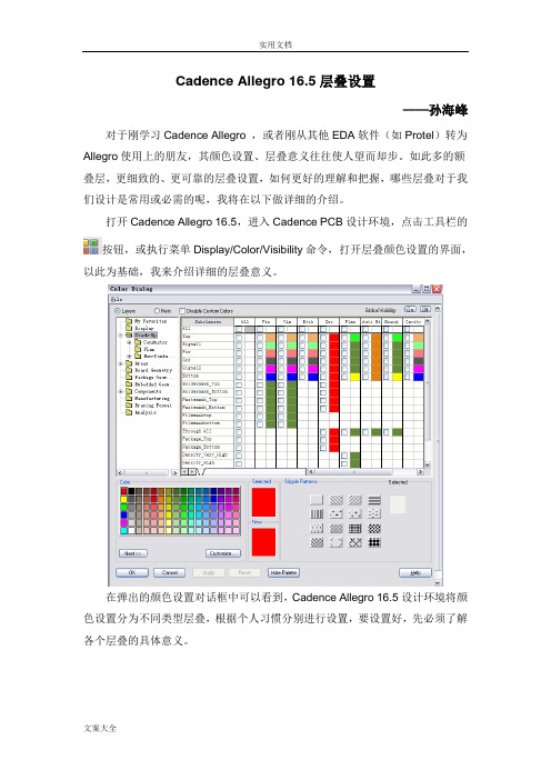
打开Cadence Allegro 16.5,进入Cadence PCB设计环境,点击工具栏的按钮,或执行菜单Display/Color/Visibility命令,打开层叠颜色设置的界面,以此为基础,我来介绍详细的层叠意义。
在弹出的颜色设置对话框中可以看到,Cadence Allegro 16.5设计环境将颜色设置分为不同类型层叠,根据个人习惯分别进行设置,要设置好,先必须了解各个层叠的具体意义。
1、 PCB基本叠层Stack-up设置a) Subclass子层叠,表示PCB中具体层叠,包括:Top层、Bottom层、内层(POW/GND)、阻焊层(Soldermask_Top/Soldermask_Bottom)、加焊层(Pastemak_Top/Pastemask_Bottom),其他Subclass子层叠目前设计中不需要用到,包括底片应用层(Filmmasktop/Filmmaskbottom)等,这些不常用的层叠不用花时间去了解的,与目前无关。
b) 子层叠相应的对象Objects,与上述的Subclass一起使用,用以显示不同子层叠上相应对象,包括子层叠上对应的Pin引脚、Via过孔、Etch走线、DRC规则错误、Plan覆铜平面、Anti Etch隔离走线(用于铜皮分割),这样既可配合子层叠,设置对应层不同对象的颜色。
此外,Boundary轮廓、Cativy埋入式器件腔体等对象暂时不用去考虑,与现在大部分PCB设计暂时没有关系。
2、PCB区域叠层Areas设置高速PCB设计经常会用到区域的概念,包括:Constraint Region高速区域约束的特殊规则区域、Route Keep Out禁止布线区域、Via Keep Out禁止放置过孔区域、Package Keep Out禁止布局区域、Package Keep In允许布局区域、Route Keep In允许布线区域,这里的区域都需要熟悉,我们在做高速协同的PCB设计时,这些区域叠层都必须用到的。
Allegro Pcb Design 小技巧
Allegro Pcb Design小技巧(上)声明:本文由一博科技原创,转载请注明出处本操作是基于Cadence Allegro平台,希望对正在使用或是准备使用allegro进行PCB设计的您有所帮助。
一、Import/Export placement的使用Import/Export placement众所周知,经常使用的一个功能,在设计中,常用于布局分工合作时合并版本,或是导出器件坐标文件,用于给贴片机输入器件坐标信息焊接使用。
但是麻雀虽小,五脏俱全,大家是否足够了解它呢?或许大家可能遇到以下两种情况:情况一:AB两人合作,A为主版本,B为辅版本,在没有采用Designparting 功能的情况下,后续A进行了原理图升级,把B负责的模块中某一类smd器件统一换成了通孔器件,此时再准备导入B做好的模块布局时,发现无法导入。
情况二:板子中有大量需要定位的表贴器件,如灯板,LED灯,开始需要定位在top面,后来结构作了大调整,需要将其定位在同样位置的bottom面。
遇到上面的情况,大家都有自己的处理方法,所谓八仙过海,各显神通嘛。
您可能是这么操作的:情况一:B先同步更新网表,保持封装一致,再导出placement,导入到A版本。
情况二:重新一个一个获取坐标定位,如果定位是等距或者有规律可循的话,那可以定位好一个之后,通过copy假器件等距放置,再进行swap置换。
您进行如上操作时是否觉得有时比较麻烦?是否想更简单一些,那可以来了解一下place_txt.txt这个文件,所谓place_txt.txt文件,我们可以直接猜测,这是获取器件的一个坐标信息,无非就是一些xy轴坐标等信息,那我们打开一个具体place_txt.txt这个文本文件来看看:大家可以清晰可以的看到第一行表示的是单位mil。
第一列是器件位号,第二列是X轴坐标,第三列是Y轴坐标,第四列是旋转度数,第五列是表示器件放在top面(空白)或者bottom面(m-Mirror的缩写),第六列是器件封装名。
- 1、下载文档前请自行甄别文档内容的完整性,平台不提供额外的编辑、内容补充、找答案等附加服务。
- 2、"仅部分预览"的文档,不可在线预览部分如存在完整性等问题,可反馈申请退款(可完整预览的文档不适用该条件!)。
- 3、如文档侵犯您的权益,请联系客服反馈,我们会尽快为您处理(人工客服工作时间:9:00-18:30)。
Cadence Allegro PCB Design SolutionAllegro® PCB Designer is a scalable, proven PCB design environment that addresses technological and method-ological challenges while making the design cycles shorter and predictable. Available in base plus options configuration, the PCB design solution contains everything needed to createa PCB layout with a fully inte-grated design flow. The base—Allegro PCB Designer—includes a common, consistent constraint management solution, PCB Editor, an auto/interactive router, as well as interfaces for manufacturing and mechani-cal CAD. PCB Editor provides a complete placement and rout-ing environment—from basicfloor-planning, placement,and routing to placement replication, advanced interconnect planning—for simple to complex PCB designs. Benefits• Offers a proven, scalable,cost-effective PCB editing and routing solution in on-demand base plus options configuration • Eliminates unnecessary iterationsthrough constraint-driven PCBdesign flow• Supports a comprehensive rule setfor physical, spacing, design forfabrication, assembly and test (DFx),high-density interconnect (HDI), andelectrical (high speed) domains• Features a common, consistentconstraint management systemfor creation, management, andvalidation of constraints from frontto back• Open environment for third partyapplication improves productivitywhile providing access to best ofbreed integrated point toolsFigure 1: Allegro PCB design solution brings together all the tools needed to design simple-to-complex PCBsPCB Editor Technology Constraint-Driven PCB Editing EnvironmentAt the heart of Allegro PCB Designer is a PCB editor—an intuitive, easy-to-use, constraint-driven environment for creat-ing and editing simple to complex PCBs. Its extensive feature set addresses a wide range of design and manufacturability challenges:• A powerful set of floorplanning and placement tools including placement replication for accelerating placement of the design• Powerful shape-based shove, hug interactive etch creation, editing establishes a highly productive interconnect environment while providing real-time, heads-up displays of length and timing margins• Dynamic shape capability offersreal-time copper pour plowing & healing functionality during placement and routing iterationsThe PCB editor can also generate a full suite of phototooling, bare-board fabrica-tion, and test outputs, including Gerber 274x, NC drill, and bare-board test in a variety of formats.Constraint ManagementA constraint management system dis- plays physical/spacing and high-speed rules along with their status (based on the current state of the design) in real time and is available at all stages of the design process. Each worksheet provides a spreadsheet interface that enables users to define, manage, and validate the different rules in a hierarchical fashion. With this powerful application, designers can graphically create, edit, and review constraint sets as graphical topologies that act as electronic blueprints of an ideal implementation strategy. Once they exist in the database, constraints can drive the placement and routing processes for constrained signals.The constraint management system is completely integrated with the PCB editor, and constraints can be validated in real time as the design process proceeds. The result of the validation process is a graphi-cal representation of whether constraintspass (highlighted in green) or fail (high-lighted in red). This approach allowsdesigners to immediately see the progressof the design in the spreadsheets, as wellas the impact of any design changes.Floorplanning and PlacementThe constraint and rules-driven method-ology of PCB design solutions includesa powerful and flexible set of place-ment capabilities, including interactiveand automatic. The engineer or designercan assign components or subcircuitsto specific “rooms” during design entryor floor- planning. Components can befiltered and selected by reference desig-nator, device package/footprint style,associated net name, part number, or theschematic sheet/page number.With thousands of components compris-ing today’s boards, precise managementis critical. Real-time assembly analysisand feedback can facilitate this manage-ment—helping designers increaseproductivity and efficiency by placingcomponents according to corporate orEMS guidelines. Dynamic design-for-assembly (DFA)-driven placement offersreal-time package-to-package clearancechecking during interactive componentplacement (see Figure 2). Driven from atwo-dimensional spreadsheet array ofclasses and package instances, real-timefeedback provides minimum clearancerequirements. Based on the package’sside-to-side, side-to-end, designers cansimultaneously place devices for opti-mum routability, manufacturability, andsignal timing.Placement ReplicationSuperior placement replication technologywithin Allegro PCB Designer allows usersto quickly place and route multiple similarcircuits in a design. It allows users to createa template using one instance of placedand routed circuit that can be applied toother instances within the design. Thesaved placement template can be usedwith other designs where similar circuitsare used. When replicating placement,users can flip or mirror the circuit from toplayer to bottom layer. All associated etchelements, including blind buried vias, aremapped to correct layers when circuit ismoved from top layer to bottom layer.Display and VisualizationThe built-in 3D viewer is available in allPCB Editor products. The 3D environmentsupports several filtering options, cameraviews, graphic display options such assolid, transparency and wireframe, andmouse-driven controls for pan, zoom, andspinning the display. 3D viewing also sup-ports the display of complex via structuresor isolated sections of the board. Multipledisplay windows can be opened using thecontext sensitive command structure, and3D images can be captured and saved inJPEG format. (see Figure 3.)The flipboard capability “flips” the designabout its Y axis inverting the design data-base in the canvas. This “flip” reorganizesthe display of the design such that whatwas displayed as top through to bottombecomes bottom through to top. Havinga true bottom side view from within theCAD system is essential for hardware Figure 2: Design For assembly (DFA) rules driven placement allows for compact placement ofcomponents without introducing errorsengineers when debugging a board in the lab, or for assembly/test engineers on the manufacturing floor. Flipboard is not just limited to viewing; design edits can also be performed while in this mode.Interactive Etch EditingThe routing feature of the PCB editor provides powerful, interactive capabili-ties that deliver controlled automation to maintain user control, while maximizing routing productivity. Real-time, shape- based, any-angle, push/shove routing enables users to choose from “shove- preferred,” “hug-preferred,” or “hug- only” modes.During etch editing, the designer can view a real-time, graphical heads-up display of how much timing slack remains for inter- connect that has high-speed constraints. Interactive routing also enables group routing on multiple nets and interactive tuning of nets with high-speed length or delay constraints.Multi-Line RoutingMulti-line routing allows users to quickly route multiple lines as a group on thePCB. Coupled with “hug-contour” option, this utility can help designers route multiple lines on the flex portion of the rigid-flex design in minutes instead of hours with traditional one trace at a time. Hug-contour option takes care of insert-ing traces with curves that are aligned to contour of the flex portion of the design. (See Figure 4.)PCB ManufacturingA full suite of phototooling, bare-board fabrication, and test outputs, including Gerber 274x, NC drill, and bare-board test in a variety of formats, can be generated. More importantly, Cadence supports the industry initiative toward Gerberless manu-facturing through its Valor ODB++ inter-face that also includes the Valor UniversalViewer. The ODB++ data format creates accurate and reliable manufacturing data for high-quality Gerberless manufacturing.High-Speed DesignIncreasing use of standards-basedadvanced interfaces such as DDR3, DDR4, PCI Express, USB 3.0 are bringing a set of constraints that must be adhered to while implementing a PCB.Allegro PCB Designer through itsHigh-Speed Option makes adhering to constraints on advanced interfaces quick and easy. It offers an extensive range of electrical rules to ensure that the PCB design implementation is complaint with the specification for advanced interfaces. Additionally, it allows users to extend the rules through the use of formulas with existing rules or post-route data such as actual trace lengths.MiniaturizationConstraint-Driven HDI Design FlowWith BGA pin pitches decreasing tobelow 1mm—0.8mm or lower with 0.65 or 0.5mm pin pitches—users are forced to implement a buildup PCB technology using high-density interconnect (HDI).While miniaturization is not necessar-ily the primary objective in many market segments, the move to buildup technol-Figure 3: Built-in 3D viewer allows reviewing of a section of the board or complex via structures with pan, zoom, rotation and spinning to reduce iterations with mechanical design teams or PCBfabricators without introducing errorsFigure 4: Multi-line routing with contour hug option accelerates through no-click routing on flexsection of the PCB designsogy is necessary for fanning out a BGA— particularly if it has three or four rows of pins on each side.The Allegro PCB Designer through its Miniaturization Option offers a proven constraint-driven HDI design flow witha comprehensive set of design rules for all different styles of HDI designs, from a hybrid buildup/core combination to a complete buildup process like ALIVH.In addition, it includes automation for adding HDI to shorten the time to create designs that are correct-by-construction. Embedded ComponentsReducing end product size can be accom-plished in many different ways. One of the approaches PCB designers are taking is to embed packaged components on inner layers. Allegro PCB Designer through its Miniaturization Option offers constraint-driven embedded component placement and routing. It supports traditional direct-attach as well as new indirect-attach tech-niques. Additionally it offers the ability to create and manage cavities on layers speci-fied for embedding components. Design Planning and Routing Highly constrained, high-density designs dominated by bussed interconnect can take significant time to strategically plan and route. Compound this with the density issues of today’s components, new signaling levels, and specific topology requirements—and it’s no wonder that traditional CAD tools and technologies fall short of capturing a designer’s specific routing intent and acting upon it. The Global Route Environment provides the technology and methodology to capture as well as adhere to a designer’s intent. Through the interconnect flow planning architecture and the global route engine, users can for the first time put their expe-rience and design intent into a tool that understands what they want—natively. Users create abstracted interconnect data (through the interconnect flow planning architecture) and can quickly converge on a solution and validate it with the global route engine. The interconnect abstrac-tion reduces the number of elements the system has to deal with—from potentially tens of thousands down to hundreds—resulting in a significant reduction in themanual interaction required.Using the abstracted data, the planningand routing process can be acceleratedby providing a visual/spatial map of theopen area in relation to the data and theuser’s design intent. The route engine canthen deal with the details of the routing,adhering to the specified intent, with-out the user having to both visualize andsolve the interconnect problems at once.This significant simplification over currentdesign tools means users converge on asuccessful interconnect solution far fasterand more easily than ever before, reduc-ing design cycle time through increasedefficiency and productivity. (See Figure 6.)Analog/RF DesignThe Allegro PCB Designer through itsAnalog/RF Design Option offers a mixed-signal design environment, from sche-matic to layout with back annotation,proven to increase RF design productivityup to 50%. It allows engineers to create,integrate, and update analog/ RF/ micro-wave circuits with digital/analog circuitsin the Allegro PCB Design environment.With its rich layout capability and power-ful interfaces with RF simulation tools, itallows engineers to start RF design fromAllegro Design Authoring, Allegro PCBDesigner, or Agilent ADS.Concurrent Team DesignGlobally dispersed design teams are onthe rise, which compounds the challengeof shortening design cycle times. Manualworkarounds that address multi-userissues are time-consuming, slow, andprone to error.Allegro PCB Design Partitioning technol-ogy provides a multi-user, concurrentdesign methodology for faster time tomarket and reduced layout time. Multipledesigners working concurrently on alayout share access to a single database,regardless of team proximity. Designerscan partition designs into multiplesections or areas for layout and editingby several design team members.Designs can be partitioned vertically(sections) with soft boundaries or hori-zontally (layers). As a result, each designercan see all partitioned sections andFigure 6: Allegro Interconnect Flow Planner technology allows users reduce layer counts and shorten design cycle through design planningFigure 5: Dynamic fileting during etch editingshaves significant time from manufacturingprep phaseupdate the design view for monitoring the status and progress of other users’ sections. Such partitioning can dramati-cally reduce over-all design cycles and accelerate the design process.PCB Autorouter TechnologyPCB routing technologies are tightly inte-grated with the PCB editor. Through the PCB Router interface, all design information and constraints are automatically passed from the PCB editor. Once the route is completed, all route information is auto-matically passed back to the PCB editor. Increased design complexity, density,and high-speed routing constraints make manual routing of PCBs difficult andtime-consuming. The challenges inher-ent in complex interconnect routing are best addressed with powerful, automated technology. The robust, production-proven autorouter includes a batch rout-ing mode with extensive user-defined routing strategy control as well as built-in automatic strategy capabilities.DFM Rules-Driven AutoroutingThe design for manufacturing capabil-ity within Allegro PCB Router signifi-cantly improves manufacturing yields. Manufacturing algorithms provide a spreading capability that automatically increases conductor clearances on a space-available basis. Automatic conduc-tor spreading helps improve manufactu-ability by repositioning conductors to create extra space between conductors and pins, conductors and SMD pads, and adjacent conductor segments. Users gain the flexibility to define a range of spacing values or to use the default values. Mitered corners and test points can be added throughout the routing process. The manufacturing algorithms auto-matically use the optimal setback range, starting from the largest to the smallestvalue. Test point insertion automaticallyadds testable vias or pads as test points.Testable vias can be probed on the front,back, or both sides of the PCB, support-ing both single side and clamshell testers.Designers have the flexibility to select thetest point insertion methodology thatconforms to their manufacturing require-ments. Test points can be “fixed” to avoidcostly test fixture modifications. Test pointconstraints include test probe surfaces, viasizes, via grids, and minimum center-to-center distance.High-Speed Constraints-DrivenAutoroutingHigh-speed routing constraints and algo-rithms handle differential pairs, net sched-uling, timing, crosstalk, layer set routing,and the special geometry requirementsdemanded by today’s high-speed circuits.The autorouting algorithms intelligentlyhandle routing around or through vias,and automatically conform to definedlength or timing criteria. Automatic netshielding is used to reduce noise on noise-sensitive nets. Separate design rules maybe applied to different regions of thedesign; for example, you can specify tightclearance rules in the connector area of adesign and less stringent rules elsewhere.Operating System SupportAllegro Platform Technology:• Sun Solaris• Linux• IBM AIX• WindowsOrCAD Technology:• WindowsCadence Services and Support• Cadence application engineers cananswer your technical questions bytelephone, email, or Internet—they canalso provide technical assistance andcustom training• Cadence certified instructors teachmore than 70 courses and bring theirreal-world experience into the classroom• More than 25 Internet LearningSeries (iLS) online courses allow youthe flexibility of training at your owncomputer via the Internet• Cadence Online Support gives you 24x7online access to a knowledge base ofthe latest solutions, technical documen-tation, software downloads, and moreFor More InformationContact Cadence sales at 1.800.746.6223or visit for additionalinformation. To locate a Cadence salesoffice or channel partner in your area, visit/contact_us.Allegro PCB Designer Base Plus Options FeaturesCadence is transforming the global electronics industry through a vision called EDA360.With an application-driven approach to design, our software, hardware, IP, and services help customers realize silicon, SoCs, and complete systems efficiently and profitably. ©2011 Cadence Design Systems, Inc. All rights reserved. Cadence, the Cadence logo, and Allegro are registered trademarks of Cadence Design Systems, Inc., All rights reserved. 22173 05/11 MP/MV/DM/PDF。
