iMC WSM视频配置案例-6W100
H3C SecPath系列防火墙典型配置案例集-6W100-SecPath系列防火墙IPSec典型配置举例

SecPath系列防火墙IPSec典型配置举例关键词:IKE、IPSec摘要:本章首先介绍了IKE和IPSec的基本概念,随后说明了防火墙的配置方法,最后给出两种典型应用的举例。
缩略语:缩略语英文全名中文解释IKE Internet Key Exchange 因特网密钥交换Security IP网络安全协议IPsec IP目录1 特性简介 (3)1.1 IPSec基本概念 (3)1.1.1 SA (3)1.1.2 封装模式 (3)2 应用场合 (4)3 配置指南 (4)3.1 配置概述 (4)3.2 配置ACL (6)3.3 配置IKE (6)3.3.1 配置IKE全局参数 (6)3.3.2 配置IKE安全提议 (7)3.3.3 配置IKE对等体 (8)3.4 IPSec安全提议 (10)3.5 配置安全策略模板 (12)3.6 配置安全策略 (14)3.7 应用安全策略组 (16)4 配置举例一:基本应用 (17)4.1 组网需求 (17)4.2 使用版本 (18)4.3 配置步骤 (18)4.4 配置结果验证 (27)4.4.1 查看IPSec安全联盟 (27)4.4.2 查看报文统计 (27)5 配置举例二:与NAT结合 (27)5.1 组网需求 (27)5.2 配置说明 (28)5.3 配置步骤 (28)5.4 配置验证结果 (34)5.4.1 查看IPSec安全联盟 (34)5.4.2 查看报文统计 (35)6 注意事项 (35)7 相关资料 (35)7.1 相关协议和标准 (35)7.2 其它相关资料 (36)1 特性简介IPsec(IP Security)协议族是IETF制定的一系列协议,它为IP数据报提供了高质量的、可互操作的、基于密码学的安全性。
特定的通信方之间在IP层通过加密与数据源验证等方式,来保证数据报在网络上传输时的私有性、完整性、真实性和防重放。
IPsec通过AH(Authentication Header,认证头)和ESP(Encapsulating Security Payload,封装安全载荷)这两个安全协议来实现上述目标,并且还可以通过IKE(Internet Key Exchange,因特网密钥交换协议)为IPsec提供自动协商交换密钥、建立和维护安全联盟的服务,以简化IPsec 的使用和管理。
最新iMC7.1智能管理平台操作手册资料
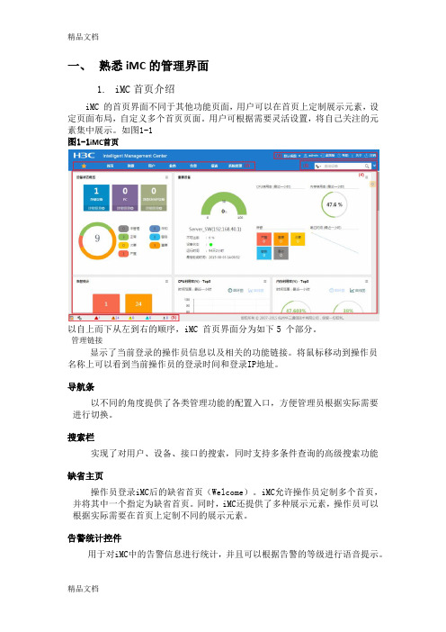
一、熟悉iMC的管理界面1.iMC首页介绍iMC 的首页界面不同于其他功能页面,用户可以在首页上定制展示元素,设定页面布局,自定义多个首页页面。
用户可根据需要灵活设置,将自己关注的元素集中展示。
如图1-1图1-1iMC首页以自上而下从左到右的顺序,iMC 首页界面分为如下5 个部分。
管理链接显示了当前登录的操作员信息以及相关的功能链接。
将鼠标移动到操作员名称上可以看到当前操作员的登录时间和登录IP地址。
导航条以不同的角度提供了各类管理功能的配置入口,方便管理员根据实际需要进行切换。
搜索栏实现了对用户、设备、接口的搜索,同时支持多条件查询的高级搜索功能缺省主页操作员登录iMC后的缺省首页(Welcome)。
iMC允许操作员定制多个首页,并将其中一个指定为缺省首页。
同时,iMC还提供了多种展示元素,操作员可以根据实际需要在首页上定制不同的展示元素。
告警统计控件用于对iMC中的告警信息进行统计,并且可以根据告警的等级进行语音提示。
2.iMC功能页界面iMC功能页界面如图1-2所示,除首页外,其他功能页的界面相同,这里仅以资源功能页为例,管理链接、功能页签和搜索栏与首页界面相同,这里不再介绍。
图1-2 功能页界面功能页界面不同于首页的地方,以从左到右的顺序,分为如下两个部分。
•自定义视图、设备视图的图标颜色与视图中严重级别最高的设备图标颜色一致;•设备视图快照下按照类别列出了网络中各类设备的数量以及设备当前的最高告警级别;•存在故障的设备列表列出了处于不同告警级别的设备,并根据严重程度进行排列,仅在存在故障设备时才显示;•性能监控区域列出了多种用户关心的性能指标。
界面中的视图、设备类型图标均为链接,点击后在操作区中将显示其中包含的设备信息列表。
3.页签下拉菜单iMC的功能页签提供了方便的下拉菜单,如图1-3所示。
图1-3 页签下拉菜单页签下拉菜单使管理员可以迅速定位到自己需要的功能,这里以业务页签为例。
IP视频PoE60W系列产品说明书

-Wire IP Video Fiber Optics SFP er Optics Media ConvertersPoE Repeaters 4K Ult Surge Protecto D DAs 60W PoE MiFiber Optics SFPs ax IP VideoFiber Optics Media Converters Analog Video over UTP HD Video & P HD-CVI over UTP HD DAsHD Video &Power Supplies60W PoE Midspans2-Wire IP Video Fiber Optics SFPsCoax IP Video Fiber Optics Media ConvertersPoE RepeatersPoE Splitters4K Ultra HD ComplientSurge ProtectorsAnalog Video over UTPHD Video & PoUHD-TVI over UTPPower Supplies HD-CVI over UTPansSymmetric Bandwidth (SBW™)Maintains maximum bandwidth throughout speci ed distances for both upload and downloads.Virtual Zero Packet Loss (VZPL™)In network communication, information is transferred in Packets. Loss of Packets equals loss of information. Tested to RFC 2544 TCP/IP for packets sizes up to 9,000 bytes Jumbo Frames.Pass-Through-PoE (PTP™)Passes through the PoE power without interfering in the PSE-PD communication.Extended Pass-Through-PoE (EPTP™)The ability to pass 802.3af/at and PoE ++ up to 74W transmitting power at extreme distances with minimal power losses.Hardened (HRD™)Vigitron products are type tested for operation from -40°C to + 75°C under tough NEMA-TS2 transportation testing standards.Low Power Consumption (LPC™)The industry’s lowest power consumption, reserving needed power for PoE devices, and saving installation and operating costs.Mega Pixel Certi ed (MPC™)Testing is done to manufacturers’ high-end Megapixel cameras. Vigitron products have also been tested by several IP camera manufacturers, resulting in their strong endorsements.RFC Certi edVigitron products are tested under RFC 2544 speci cations for Packet loss, Bandwidth and Latency and the highest Jumbo frame size of 9,000 bytes, which provides the ability to transmit the largest megapixel size cameras with virtually no loss.RFCC ™LPC ™HRD ™-40C+75CSupport Jumbo Frames (JFC ™)Jumbo Frame compatibility assures reliable full bandwidth transmission of the highest megapixel cameras with maintaining image quality at high frame rates.Vigitron products are tested up to the full jumbo frame rate of 9000 bytes.60W PoEVigitron PoE++ products transmit up to 74W power at extended distances to cameras with PTZ, IR Illuminators, heaters and blowers, eliminating the need for any local power supplies and power outlets.Vigitron AdvantagesPoE++60WOur most important products are free!L i f e t i m e W a r r a n t y L i f e t i me W a r r a n t y L if et i m e W a r r a n ty Vigitron vs. CompetitionFeature Vigitron CompetitorsComplete IP Infrastructure ProviderX Free Design ServicesX Performance Backed by Certi ed TestingX Highest BandwidthX Highest PoE Power CapacityX Real World Product TestingX IP Camera Interoperability TestingX Products Made in USAX Industry’s Longest WarrantyX Vigitron’s Lifetime WarrantyVigitron, with about 2 decades of design and manufacturing experience, provides the most reliable products supported by the industry's longest warranty. Our warranty is the production lifetime plus three years to assure you of continued support, even after a product's end of life. Design Services and Extended W arranty are two of V igitron's most important and free products.MaxiiNet™ High Power Managed PoE SwitchesVi3026 PoE Switch Data + PowerPoE CamerasNVRExtended distance CoaxVi2401AVi2401AData + PowerData + PowerExtended distance CoaxVi2301AVi2301AThe Vi3010 is a high power PoE switch that provides 10 Gb ports and 2 SFP sockets for fiber Vi3010 PoE Switch Master ControlBuilding#2Building#1Building#3Data + PowerPoE CamerasNVRExtended distance CoaxVi2401AVi2401AData + PowerData + PowerData + PowerExtended distance CoaxVi2301AVi2301AVi3026/Vi3326Vi3026Vi3010Vi3010Model FunctionVi31055-Port 60W PoE Powered PoE Switch w/ UTP and Fiber Uplink Vi300560W60W Vi32055-Port 60W PoE Powered PoE Switch W/ Extended UTP Uplink 5-Port PoE Powered PoE Switch W/ Extended Coax UplinkApplication DiagramsVi2216ANVRVi3326Network SwitchMaxiiNet Vi3005™5-port PoE Powered PoE Switch328 ft. (100m) Cat-5Data + 60W PoE328 ft. (100m) Cat-5, Data + PoEVi3005PoE Cameras60WNVRData + 60W PoE328 ft. (100m) Cat-5, Data + PoEVi3105PoE CamerasVi2316AVi2216ANVRExtended Coax up to 3,000 ft. (914 m)Data + 30W PoE328 ft. (100m) Cat-5, Data + PoEVi3205PoE CamerasVi2416ANVRThe Vi3005 is a Layer 2 PoE switch that can be powered by PoE or local power supply. It The Vi3105 is a layer 2 PoE switch that can be powered by PoE or local power supply and The Vi3205 is a layer 2 PoE switch that can be powered by PoE or local power supply and Vi3326Network SwitchVi3026PoE SwitchMaxiiNet ™ Hardened PoE Powered PoE SwitchModel FunctionMaxiiCopper ™ Ethernet Extenders over CoaxSingle port 10/100 Ethernet Extender w/ Pass-Through-PoE • Extends 10BaseT up to 5,000 ft. (1,524m)• Extends 100BaseT up to 1,800 ft. (548m)• Provides Pass-Through-PoE up to 30W • Provides automatic Bandwidth detectionVi2401A Vi2404A Vi2408A 4-port 10/100 Ethernet Extenderw/ Pass-Through-PoE 8-port 10/100 Ethernet Extenderw/ Pass-Through-PoE Vi2416A16-port 10/100 Ethernet Extenderw/ Pass-Through-PoEMini Ethernet Extender w/ Pass-Through-PoE Vi2400A Data & PoE Range*Vi3026 PoE SwitchPoE CamerasNVRExtended distance CoaxVi2401AVi2400AVi3026 PoE SwitchData + PowerPoE CamerasNVRExtended distance CoaxVi2401AVi2401AJunction BoxThe Vi2401A is the perfect solution for analog systems transitioning to IP . It reduces the installation cost by maintaining existing coax wiring. Pass-Through-PoE eliminates the need for local power supplies for the extender and IP camera at the remote site.Vi2416APoE CamerasNVRExtended distance Coax, Data + PoEExtended distance Coax, Data + PoEUp to 328 ft. (100m) Cat-5Data + PoEVi2401AVi2401AMulti Port MaxiiCopper ™ over Extended CoaxVi2216ANetwork Switch The Vi24xxA series Pass-Through-PoE eliminate the need for local power supplies for the extender and IP camera at the remote site.Vi2416APoE CamerasNVRExtended distance Coax, Data + PoEExtended distance Coax, Data + PoEUp to 328 ft. (100m) Cat-5Data + PoEVi2401AVi2401AMulti Port MaxiiCopper ™ over Extended CoaxVi3026 PoE Switch The Vi24xx series are capable of running data and PoE power over single pair twisted or Up to 328 ft. (100m) Cat-5PoE CamerasVi2416AVi2401AVi0030Vi0030Vi2216ANVRNetwork SwitchVi2401A• Extends 10BaseT up to 3,000 ft. (914m)MaxiiCopper ™ Ethernet Extenders over UTPVi3026 PoE SwitchPoE CamerasNVRExtended distance UTPVi2301AVi2301AThe Vi2301A can transmit power sources up to 74 W providing the power for PoE PTZ dome PoE CamerasVi2301AVi2301AVi2301ANVRNetwork Switch60W PoE CameraVi2216 MidspamJunction BoxVi2300AExtended distance UTPUp to 328 ft. (100m) Cat-5PoE CamerasVi2316AVi2301AVi2216ANVRNetwork Switch Vi2301AThe Vi2701RX and Vi2301A combination provides a single channel extended distance high Extended distance Cat-5, Data + PoEExtended distance Cat-5, Data + PoEVi2301ANVRNetwork SwitchVi2301AVi2301AVi2701TXVi2216APoE Camera60W NVRNetwork SwitchPoE CameraPoE CameraVi2301AVi2301ANVRNetwork Switch The Vi2701 is not only an extended distance data and 60W PoE solution, but it is also an Vi2701TXPoE CamerasVi2701RXVi2701RXVi1120Vi1120Vi1120Vi310560NVRNetwork Switch60W PoE Camera60W PoE CameraVi2300WVi2300Vi2701RXVi2701RXVi1120Vi1120MaxiiNet ™ Hardened PoE Powered PoE SwitchNVRVi3405PoE CamerasNVRVi3305PoE CamerasExtended Coax up to 3,000 ft. (914 m)Vi1120Vi1120Vi3326Network Switch328 ft. (100m)Vi3326Network Switch328 ft. (100m)Vi2300A60W PoE CameraData + 30W PoE Vi0015Vi2301A Vi2301ANVRVi3305Vi1120Vi3326Network Switch328 ft. (100m)IP PhoneVi2300AVi2400AVi2301AWiFi RouterMaxiiPower ™ High Power PoE MidspansPoE CamerasData + PoEData + PoEExtended distance CoaxExtended distance CoaxVi2401ANetwork SwitchNVRVi2401AVi2301AVi2301AVi2216ANetwork Switch NVRVi2202Vi2202PoE CameraPoE Camera PoE CameraVi112060WPoE CameraMaxiiPower ™Single port PSENetwork Switch NVRVi220130W PoE CameraDataDataMaxiiPower ™ High Power Extended Coax PoE MidspansVi2616PoE CamerasNetwork SwitchNVRExtended distance Coax, Data + PoEExtended distance Coax, Data + PoEData + PoEVi2401AVi2401AThe Vi24xx series are capable of running data and PoE power over single pair twisted or Up to 328 ft. (100m) Cat-5PoE CamerasVi2416Vi2401Vi2401Vi0030Vi0030Vi2216NVRNetwork SwitchNVR Network SwitchPoE Camera60W Vi2516Vi2701TXVi2301AUp to 328 ft. (100m) Cat-5NVR Network SwitchPoE Camera60W Vi2516Vi2701TXVi2701TX Up to 328 ft. (100m) Cat-5The above solution is ideal for PoE applications requiring power greater than 802.3at (30W) i2301A provides Pass-Through-PoE (PTP™) without the need for local power sources. It is Vi2516PoE CamerasNVRNetwork SwitchUp to 328 ft. (100m) Cat-5Vi2301AVi3105MaxiiPower ™PoE SplitterNetwork Switch NVRVi2201DatalightIRVi22201Data MaxiiPower ™PoE SplitterNetwork Switch NVRVi2201DataNon-PoE CameraVi22101Data Extended distance CoaxExtended distance UTPVi2401A Network SwitchNVRVi2401AVi2301A Vi2301AVi2216AVi22201Vi22201Data DataEmergency SystemsWiFi RouterNVR328 ft. (100m) Cat-5Data + PoEPoE CamerasVi2216ANVRVi3003 3-port Drop & Insert 60W PoE SwitchDataData + 60W PoE Vi3003Vi3003Vi3003328 ft. (100m) Cat-5Data + 30W PoEVi3103Vi3103Data 60W PoEPoE Cameras328 ft. (100m) Cat-5The Vi3003 enables 1G connection between network switches eliminating the need for PoE CamerasVi3103328 ft. (100m) Cat-5328 ft. (100m) Cat-5328 ft. (100m) Cat-5Vi300360W PoE PTZ Camera328 ft. (100m) Cat-5, Data328 ft. (100m) Cat-5Data + 60W PoE NVRVi3326 Network SwitchVi3003Vi1120328 ft. (100m) Cat-5Data + 30W PoEThe Vi3103 is both a repeater and L2 3-port network switch providing drop and insert The Vi3003 is both a repeater and L2 3-port network switch providing drop and insert capability. Vi3003 allows for transmission of two cameras over a single cable or adding a new camera Vi3326 Network SwitchVi3026 PoE Switch328 ft. (100m) Cat-5IRPoE Camera328 ft. (100m) 1000BaseT328 ft. (100m) 1000BaseTVi0012Vi3003Network SwitchNetwork SwitchNetwork SwitchVi0025Vi2216ANVRNetwork SwitchPoE CameraPoE CameraVi3002W #8Vi3002WVi3002W #2Vi3002W #1NVRNetwork Switch Vi2216APoE Camera60W NVRNetwork Switch Vi2216A PoE Camera30W Up to 328 ft. (100m) Cat-5Vi3002Up to 328 ft. (100m) Cat-5Up to 328 ft. (100m) Cat-5Up to 328 ft. (100m) Cat-5Data + 60W PoEUp to 328 ft. (100m) Cat-5Vi3002Vi3002Vi3002Vi3002The Vi3002W complies with IP67 standards eliminating extra housing costs. Its unique enclosureNVRNetwork Switch PoE Camera60W Vi2516AVi2701TXVi2701TXUp to 328 ft. (100m) Cat-5MaxiiCopper ™ 60W PoE and Ethernet ExtendersNVRNetwork Switch PoE Camera60W Vi2701RXVi2701RXVi2701TXVi2701TXi2804AP combination can power up to 4 remote cameras by providing 74W NVRNetwork SwitchPoE CamerasVi1120Vi1120Vi1120Vi1120Vi1120Vi2701RXVi2301AVi3105Vi2701RXVi2701RXNetwork Switch NVRVi2202PoE Camera60W PoE CameraVi1120PoE AccessoriesNetwork SwitchNVRVi001560W PoE Camera328 ft. (100m) 1000BaseT328 ft. (100m) 1000BaseTVi0012Vi3003Network SwitchNetwork SwitchNetwork SwitchVi0025Vi2216ADataVi2216 PoE MidspanNetwork SwitchNVRViewMate™ Data + PowerData + PowerPoE CameraPoE CameraExtended Distance UTPStandard Distance UTPIP Camera Test ToolsVi0021Vi0019MaxiiFiber ™ Fiber Optics Transmision EquipmentNVRNetwork SwitchPoE CameraVi5001Vi0017NVRNetwork SwitchPoE CameraVi5001 + SFPVi0017Vi5001 + SFPVi0017NVRNetwork SwitchVi5004328 ft. (100m) Cat-5Vi0017Vi5001PoE CamerasVi51000Vi0012The Vi51004 is a 4-port Media converter receiver. It works in conjunction with Vi51000 Fiber HD DVRVi51001HD CameraVi0017HD DVRVi51004Vi51000HD CamerasVi0012HD CameraVi61001MVi10004HD CamerasVi10004i1004 can transmit 4 HD videos on a single Cat5/6 cable to save installation time and cost.4 x HD Video over Cat5/6CoaxVi10001MVi10016HD DVRHD CamerasVi10001FVi10001MVi10001PHD DVRHD DVRVi10001MHD DVRHD CamerasHD DVRHD Cameras Vi10001MVi61000Vi61000Vi61001HD DVRHD CameraVi15001Vi15000HD DVRVi15016Vi15000Hd Video + 12VDCHD CameraHd Video + 12VDCApplication DiagramsHD DVRHD CamerasHD Cameras Vi16004Vi16002HD DVR Vi18016Vi18000HD CameraHd Video + 12VDCHD Video & Power over CoaxVi18000HD CameraHd Video + 12VDC Vi18001*Available November 2015Video SolutionsPassive TransceiversModel Surge Protection*VB1001FVB1001MVB1001PVB1007MTransmittersVideo, Power & Data Solutions。
iMC产品安装部署详细介绍

部署
安装->部署
8
目录
iMC安装和部署的概念 iMC产品的安装方法 iMC产品的部署方法 iMC产品的卸载方法
iMC安装(一)
安装时请参考安装指导说明书
安装组件/目标文件夹选择界面
一个iMC的安装盘中,可能存在多 个组件,该界面给出组件列表; 各组件存在一定依赖性,如果被依 赖的组件没有安装,则不允许安装依 赖组件(此时,可以在不允许安装的 组件上激活鼠标右键菜单,查看组件 依赖关系)。 如果服务器上已经安装过iMC,则 安装位置不允许重新选择。
4
iMC的安装和部署要求
iMC的安装和部署准备工作和操作过程请严格按照产品的版本说明书 和安装指导书进行。 操作系统和数据库的安装本章不做阐述,请参考操作系统和数据库安 装的相关文档。 iMC服务器硬件要求请参考版本说明书和安装指导说明书,服务器软 件要求请参考。具体情况在部署的章节中也有补充说明。
EAD EPON 功 功能组件 MVM NTA UBA WSM QoS 管理 功 功 功 功 功 能 功 能 能 能 能 能 … 组 能 组 组 组 组 组 组 件 UAM 件 件 件 件 件 件 功能组件 产品 平台
iMC平台 (专业版)
iMC平台 (标准版)
iMC平台 (中小企业版)
可以在开始菜单、或控制面板->添加或删除程序中,找到卸载程序的 入口; 卸载iMC产品与卸载组件不同,卸载产品时,所有安装在本机的组件 将全部被删除; 卸载过程中,所有iMC服务进程都将自动停止; 如果使用分布式部署,则在执行iMC产品的卸载操作前,务必确保:
从服务器端:确保所有部署于此服务器上的组件均已经成功卸载; 主服务器端:确保所有从服务器已经全部卸载完成。
H3C_防火墙典型配置案例集(V7)-6W100-H3C_防火墙IPsec典型配置案例(V7)

[Sysname] pki import domain domain1 der ca filename m9000.cer The trusted CA's finger print is:
MD5 fingerprint:7B6F 9F0B F2E8 8336 935A FB5B 7D03 64E7 SHA1 fingerprint:2040 0532 2D90 817A 3E8F 5B47 DEBD 0A0E 5250 EB7D Is the finger print correct?(Y/N):y
i
ቤተ መጻሕፍቲ ባይዱ
1 简介
本文档介绍 M9000 多业务安全网关和 F5000-S 设备建立 IPsec 隧道的方法,其中 IKE 的认证使用 证书方式。
2 配置前提
本文档不严格与具体软、硬件版本对应,如果使用过程中与产品实际情况有差异,请参考相关产品 手册,或以设备实际情况为准。 本文档中的配置均是在实验室环境下进行的配置和验证,配置前设备的所有参数均采用出厂时的缺 省配置。如果您已经对设备进行了配置,为了保证配置效果,请确认现有配置和以下举例中的配置 不冲突。 本文档假设您已了解 IPsec 特性。
1
3.3 使用版本
本举例是在 M9000 Version 7.1.051, Ess 9105 版本上和 F5000-S 的 T3803P02 版本上进行配置和验 证的。
3.4 配置步骤
3.4.1 M9000 的配置
申请证书有在线申请和本地导入两种方式,本配置采用本地导入方式。
(1) 配置接口 Ten-GigabitEthernet5/0/11、Ten-GigabitEthernet5/0/12 的 IP 地址。 # 配置接口 Ten-GigabitEthernet5/0/11 的 IP 地址。
H3C iMC维护手册v1.0

目录1 维护入门......................................................................................................................... 1-11.1 iMC PLAT(平台)基础知识 ............................................................................................ 1-11.1.1 系统角色和操作员分组........................................................................................ 1-11.1.2 iMC PLAT目录结构 ........................................................................................... 1-21.1.3 iMC PLAT常用文件说明..................................................................................... 1-21.1.4 iMC PLAT后台程序日志文件说明........................................................................ 1-31.1.5 iMC PLAT 相关数据库说明 ................................................................................. 1-51.1.6 iMC PLAT相关进程说明.................................................................................... 1-61.2 iMC UAM/EAD/CAMS组件基础知识 ............................................................................ 1-71.2.1 iMC UAM/EAD/CAMS系统角色分类 ................................................................... 1-71.2.2 iMC UAM/EAD/CAMS组件目录结构 ................................................................... 1-71.2.3 iMC UAM/EAD/CAMS常用文件说明 ................................................................... 1-81.2.4 iMC UAM/EAD/CAMS常用日志文件说明............................................................. 1-91.2.5 iMC UAM/EAD/CAMS相关数据库说明............................................................... 1-141.2.6 iMC UAM/EAD/CAMS相关进程说明 ................................................................. 1-141.3 iNode基础知识 .......................................................................................................... 1-151.3.1 iNode目录结构................................................................................................. 1-151.3.2 iNode常用文件说明 .......................................................................................... 1-161.3.3 iNode常用日志文件说明.................................................................................... 1-161.3.4 iNode相关进程说明 .......................................................................................... 1-181.4 iMC WSM(无线业务管理)组件基础知识 ........................................................................ 1-191.4.1 常用文件说明.................................................................................................... 1-191.4.2 日志文件说明.................................................................................................... 1-191.4.3 数据库说明 ....................................................................................................... 1-211.4.4 iMC WSM进程说明 .......................................................................................... 1-211.5 iMC BIMS(分支网点智能管理系统)基础知识 ............................................................. 1-211.5.1 系统角色和操作员分组....................................................................................... 1-211.5.2 iMC BIMS目录结构 .......................................................................................... 1-221.5.3 iMC BIMS常用文件说明.................................................................................... 1-221.5.4 iMC BIMS后台程序日志文件说明....................................................................... 1-231.5.5 iMC BIMS 相关数据库说明 ................................................................................ 1-251.5.6 iMC BIMS相关进程说明.................................................................................... 1-251.6 iMC MVM(MPLS VPN业务管理)组件基础知识 ............................................................. 1-261.6.1 常用文件说明.................................................................................................... 1-261.6.2 日志文件说明.................................................................................................... 1-261.6.3 数据库说明 ....................................................................................................... 1-281.6.4 iMC MVM进程说明........................................................................................... 1-281.7 iMC IVM(IPsec VPN业务管理)组件基础知识................................................................ 1-291.7.1 常用文件说明.................................................................................................... 1-291.7.2 日志文件说明.................................................................................................... 1-291.7.3 数据库说明 ....................................................................................................... 1-301.7.4 iMC IVM进程说明............................................................................................. 1-311.8 iMC NTA/UBA基础知识 ............................................................................................. 1-311.8.1 iMC NTA/UBA目录结构.................................................................................... 1-311.8.2 iMC NTA/UBA常用文件说明 ............................................................................. 1-321.8.3 iMC NTA/UBA后台程序日志文件说明 ................................................................ 1-321.8.4 iMC NTA/UBA 相关数据库说明.......................................................................... 1-331.8.5 iMC NTA/UBA相关进程说明 ............................................................................ 1-331.9 iMC SOM(服务运维管理)基础知识 ........................................................................... 1-341.9.1 iMC SOM组件说明........................................................................................... 1-341.9.2 iMC SOM目录结构........................................................................................... 1-341.9.3 iMC SOM常用文件说明 .................................................................................... 1-341.9.4 iMC SOM相关数据库说明 ................................................................................. 1-341.9.5 iMC SOM相关进程说明 ................................................................................... 1-351.10 iMC QoSM基础知识................................................................................................. 1-351.10.1 系统角色和操作员分组..................................................................................... 1-351.10.2 iMC QoSM 目录结构....................................................................................... 1-351.10.3 iMC QoSM 相关数据库说明 ............................................................................. 1-352 iNode ............................................................................................................................. 2-12.1 基本功能..................................................................................................................... 2-12.1.1 防内网外连 ........................................................................................................ 2-13 iMC 服务器例行维护........................................................................................................ 3-13.1 操作系统维护:........................................................................................................... 3-13.1.1 Windows操作系统:.......................................................................................... 3-13.2 数据库维护 ................................................................................................................. 3-33.2.1 安全注意事项:.................................................................................................. 3-33.3 iMC 监控管理代理 ....................................................................................................... 3-34 iMC各组件常用维护方法 ................................................................................................. 4-14.1 iMC PLAT(平台)维护................................................................................................... 4-14.1.1 在新装Windows操作系统中通过IE浏览器无法登录iMC系统,如何解决? ............. 4-14.1.2 平台字符串查询的匹配规则。
iMC(WSM)体验中心操作说明
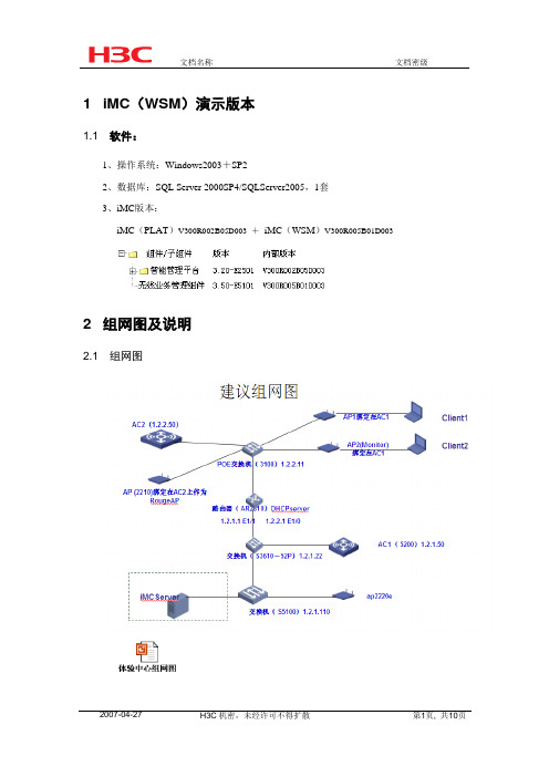
1 iMC(WSM)演示版本1.1 软件:1、操作系统:Windows2003+SP22、数据库:SQL Server 2000SP4/SQLServer2005,1套3、iMC版本:iMC(PLAT)V300R002B05D003 +iMC(WSM)V300R005B01D0032 组网图及说明2.1 组网图2.2 组网说明:2无线AC5002(2台)分别为AC1、AC2设备版本B56D0013FitAP(4台)(可全部WA2100)设备版本B56D0014交换机,3台,(作为AC和FitAP之间设备使用,可选用S3600)配置IP地址及SNMP参数,加入到网管中;4、路由器,1台,(可选用AR2810)注:AC和FitAP之间可用加入路由器多台交换机,若查看更复杂的拓扑需增加相关设备5、PC服务器,1台,3GHzCPU+4G内存+80G硬盘或以上,Windows Server 20036、便携或其它无线终端设备(带无线网卡即可),数量可根据需要来定,至少1台3 演示环境搭建3.1 iMC(WSM)环境搭建2在服务器上安装SQLServer2000(SP4)或SQLServer2005数据库,3安装iMC平台以及WSM版本iMC(PLAT )3.20-E2501(V300R002B05D003);iMC(WSM)3.50-E5101(V300R005B01D003);9按组网图搭建网络,对AC及FitAP设备进行相关配置,保证无线客户端可以上线;AC和FitAP之间的交换机或路由器设备需配置SNMP参数,保证可用加入网管。
10将其中一台FitAP,配置device-detection enable命令,做为监控RougeAP的AP。
11将AC和FitAP绑定,配置无线设备服务策略,使无线客户端连接到AP上,(注意需要手工绑定,不能采用自动绑定方式)。
AC相关配置:22准备安装有无线网卡的便携机或者其他无线客户端。
高清解决方案解决方案

4×4拼接上墙参考实例
相关技术介构建大、中型的高清 视频监控系统,以解决小型监控系统中单台NVR无法满 足大路数摄像机的接入问题。
系统可以通过该管理平台将系统中分布在各个地理 区域的网络摄像机、NVR、流媒体服务器、客户端主机 以及高清解码盒统一接入、配置和管理。
中控软件的应用环境和界面
相关技术介绍
流媒体转发
WAPA的NVR平台自身即 可完成对视频流的复制和转发, 以便于网络上的客户端调阅, 当NVR被大路数的客户端并发 请求时,为了缓解NVR数据读 写的压力,可以在后端平台增 加部署WAPA的流媒体代理组 件,以此来缓解大路数路视频 复制分发的压力。
解决方案(四): 视频监控管理平台解决方案
面向的对象
系统建设提出通过各个功 能模块实现大路数接入、多级 联网、监控第三方的视频设备、 高业务应用时的解决方案
系统结构
系统建设所面临的挑战
1、兼容友商的视频编解码设备
我们都知道,当下行业内前、后端的设备都还不能实现真正意义上的互联互通,因 此当平台厂家要接入我们的摄像机、DVR或NVR时,就需要进行系统之间的对接。
通过标准ONVIF、摄像机SDK、通讯协议、SIP协议等完成设备接入。
2、大规模采用NVR堆叠的方式,不能有效发挥各个功能组件的最大效能。 解决方法:视频监控平台将各业务组件独立化,以发挥各模块组件的最大效能,
一般包括数据库模块、存储模块、解码模块、转发模块、客户端模块等。
3、系统间需要跨级、跨域的相互访问和控制等 解决方法:通过核心数据库统一管理用户信息、设备信息、日志信息等
视频/报警联动方案(二) 通过报警主机和中控CMS对接实现报警联动。一
旦触发,能够完成报警触发抓拍、报警触发 录像、警灯/警号报警、电子地图联动、解码 /大屏联动等响应措施。
布朗安全系统视频系统技术说明:布朗视频内容分析算法功能说明书
VCA Capabilities per Device with FW 8.40 Technical NoteBosch Security Systems | Video Systems 2 | 11 Table of contents1Introduction31.1Overview of video content analysis algorithms (3)2Resolution & minimal object sizes42.1MOTION+ (4)2.2Essential Video Analytics (5)2.3Intelligent Video Analytics (5)2.4Intelligent Video Analytics FLOW (6)2.5Camera Trainer (6)2.6Traffic Detector (6)3Frame rates74Moving camera (AUTODOME / MIC) & VCA74.1Profiles vs Scenes (7)4.2Reference Image (7)4.3Detect “object in field” even during camera motion (8)4.4Intelligent Tracking (8)5Thermal camera & VCA86MIC IP fusion 9000i87Video analytics features: Differences by device98Video analytics features by version10Bosch Security Systems | Video Systems 3 | 111IntroductionDifferent devices, whether cameras or encoders, offer a different amount of processing power for video contentanalysis (VCA). This has effects on the supported feature set and detection distance. All Bosch IP cameras &encoders can be clustered by their “Common Product Platform” (CPP), so the CPP version will be used tosummarize the differences between the versions. Further differences are introduced because new features areoften added with FW updates, because thermal camera videos have different visual properties than those ofnormal cameras, and because moving cameras (AUTODOME/MIC) sometimes need different handling. In thistech note, all of these differences are collected.1.1Overview of video content analysis algorithmsThere are different types of video content analysis (VCA) algorithms available:DescriptionTamper detection •Detect if camera is obscured or moved•Evaluate overall lighting level (too dark / bright)•Detect removed or placed objects in dedicated areas (reference image check)MOTION+•Change detection to trigger recordingEssential Video Analytics •Intrusion detection for smaller, controlled environments •Simple counting / queuing applicationsIntelligent Video Analytics •Mission critical perimeter protection•Outdoor environments with harsh weather conditions•Long detection ranges•Ship tracking•Exhibit protection•Counting / queuing applications•Camera Trainer•Intelligent Video Analytics includes the full Essential Video Analytics feature setIntelligent Tracking (MIC/AUTODOME/ MP cameras only)•AUTODOME / MIC automatically zoom to & follow a selected object •Megapixel cameras: “Virtual PTZ”, cutout stream follows selected object in the camera field of viewCamera Trainer •Self-train detectors for simple, rigid objects.•Camera Trainer is an extension of Intelligent Video AnalyticsTraffic Detector (INTEOX only)•Traffic monitoring up to high traffic density, as well as parked cars and pedestrians. Includes classification of car, bus, truck, bicycle, motorbike and persons.•Traffic Detector is an extension of Intelligent Video AnalyticsBosch Security Systems | Video Systems 4 | 112Resolution & minimal object sizes2.1MOTION+MOTION+ aggregates pixel information into processing blocks. These blocks are, in the internal resolutionused for processing, 8x8 pixel with no overlap to neighbouring blocks from FW 6.10 onward. At the imageborder, there is an insensitive area with a width of approximately one block.Aspect Ratio Internal Resolution BlockSizeNumber ofBlocks x Y x y1:13203208x838384:33202403828 16:93201803821 MOTION+ blocksBosch Security Systems | Video Systems 5 | 112.2Essential Video AnalyticsEssential Video Analytics usually subsamples the video before processing it, resulting in the following internalprocessing resolutions:Aspect Ratio / Format IVA ResolutionComment x y4:33202403:4240320DINION / FLEXIDOME: 90° / 270° image rotation16:93201809:16180320DINION / FLEXIDOME: 90° / 270° image rotationAny object with an area of less than 10 square pixels in this internal resolution is discarded. A minimum object area of 20 square pixel is recommended for object detection.2.3Intelligent Video AnalyticsIntelligent Video Analytics usually subsamples the video before processing it, resulting in the following internal processing resolutions, which depend on camera platform, firmware version and configuration of Intelligent Video Analytics:Platform AspectRatio /FormatIVA ResolutionComment x yCPP6/7/7.3/13/14 ≥FW 6.30 & double distanceactive 1:1640640FLEXIDOME IP panoramic 7000 MP 360°4:36404803:4480640DINION / FLEXIDOME: 90° / 270° image rotation 16:96403609:16360640DINION / FLEXIDOME: 90° / 270° image rotationCPP6/7/7.3/13/14 ≥FW 6.30 & double detectioninactive 1:1320320FLEXIDOME IP panoramic 7000 MP 360°4:33202403:4240320DINION / FLEXIDOME: 90° / 270° image rotation 16:93201809:16180320DINION / FLEXIDOME: 90° / 270° image rotationFLEXIDOME panoramic5000i & double detectiondistance active1:1480480FLEXIDOME panoramic5000i & double detectiondistance inactive1:1240240FLEXIDOME multi 7000i & double detectiondistance active 4:3320240 16:9320180FLEXIDOME multi 7000i & double detectiondistance inactive 4:3160120 16:916090Double detection distance is active for the following configurations & objects:④Tracking modes: 3D tracking, 3D people tracking④Noise suppression: OFF, MEDIUM④Object type: Moving, started, stoppedAny object with an area of less than 10 square pixels in the IVA resolution will be discarded. A minimum object area of 20 square pixel is recommended for object detection.2.4Intelligent Video Analytics FLOWIntelligent Video Analytics FLOW aggregates pixel information into motion vectors per processing block. These blocks are, in the internal resolution used for processing, 8x8 pixel large with no overlap to neighbouring blocks. At the image border, there is an insensitive area with a width of approximately one block.Aspect Ratio Internal Resolution BlockSizeNumber of Blocks x Y x y1:13203208x838384:3320240382816:932018038212.5Camera TrainerWhen Camera Trainer is available, it uses the following resolutions and a minimal object size of 32x32 pixel. All Camera Trainer objects have a size which is a multitude of 8x8 pixel blocks, or 16x16 pixel blocks for larger objects.Platform AspectRatio /FormatIVA ResolutionComment x yCPP6/7/7.3/13/141:1640640FLEXIDOME IP panoramic 7000 MP 360°4:36404803:4480640DINION / FLEXIDOME: 90° / 270° image rotation 16:96403609:16360640DINION / FLEXIDOME: 90° / 270° image rotationFLEXIDOME panoramic5000i1:1480480FLEXIDOME multi 7000i 4:3320240 16:93201802.6Traffic DetectorPlatform AspectRatio /FormatIVA ResolutionComment x yCPP 134:3640480 16:96403603Frame ratesIntelligent Video Analytics, Intelligent Video Analytics FLOW, Essential Video Analytics and MOTION+ are always processed on the first stream. Depending on the maximal possible frame rate, or frames per second (fps) of this stream,Maximalfps1rst steamIntelligent VideoAnalytics / EssentialVideo AnalyticsfpsMOTION+fps25 / 5012,5530 / 601558,338,335Exception is the FLEXIDOME multi 7000i, where Intelligent Video Analytics runs with 7.5 fps.If the actually used frame rate of the first stream is lower, then the metadata and alarms are still generated with the frame rate specified here. If such a recording is viewed, then the displayed metadata will change faster than the video images themselves.There are a few cases where the frame rate drops below:∙Exposure time is too large. This can be avoided by ensuring that minimal frame rate in automatic exposure mode is not smaller than the specified Intelligent Video Analytics / Intelligent Video Analytics FLOW / Essential Video Analytics / MOTION+ frame rate.∙Intelligent Video Analytics / Essential Video Analytics has to track too many objects simultaneously. This can happen with 3D person tracking mode in crowds. At the moment, ~10 objects can be tracked in real time with Intelligent Video Analytics on CPP4, ~20 objects with Intelligent Video Analytics on CPP6/7 and ~10 objects with Essential Video Analytics. Beyond that, frame drops may occur because processing took longer than available for the frame.Nevertheless, Intelligent Video Analytics / Essential Video Analytics will still continue to track the objects.∙Camera Trainer: Due to larger image size in the panoramic cameras, Camera Trainer results may not be available every frame, causing outlines and alarms to flicker.4Moving camera (AUTODOME / MIC) & VCAMany VCA algorithms are designed for non-moving cameras only, and will not work while the camera is moved. Therefore these algorithms are only available on predefined dome scenes. They will start the moment the scene is reached and be stopped on departure.4.1Profiles vs ScenesOn non-moving cameras, up to two VCA profiles are supported, which can be scheduled or switched via an internal or external trigger event. Moving cameras, however, are typically used different than non-moving cameras. They are typically configured to move to different scenes after a certain time span, in order to monitor more area than with a single camera. This would collide with any attempt to schedule the VCA on a single scene. Thus, while up to 16 scenes are supported with VCA, only a single VCA profile is available on each scene, and scheduling is not available.4.2Reference ImageDue to limited on-board storage and the fact that not only two but 16 reference images need to be stored on moving cameras, the VCA algorithms relying on a reference image, that is reference image check for tamper detection and crowd density estimation, have long not been supported and are only available from FW 6.20 onward on CPP4 and newer.4.3Detect “object in field” even during camera motionOutside of prepositions and even while the PTZ camera is moving, whether on guard tours or manually, Intelligent Video Analytics can now detect and alarm on “object in field” on PTZ cameras. These alarm fields are defined globally across all potential PTZ views, and any part of those global fields currently within the cameras view becomes active. Thus, guard tours sweeping across the monitored areas in order to provide an intruder less time to slip by can now automatically alarm on those intruders as well. Geolocation of the tracked objects is now provided if the camera is calibrated and assigned a location in the corresponding coordinate system. This is only available on PTZ cameras of CPP 7.3 and newer. Not available on the thermal video of MIC IP fusion 9000i.4.4Intelligent TrackingMoving cameras with Intelligent Video Analytics also have a special VCA algorithm called Intelligent Tracking. When triggered by an Intelligent Video Analytics or the manual selection of an Intelligent Video Analytics object by a user, the Intelligent Tracking steers the moving camera all by itself to zoom in on the object for most details and to follow this object. When the object stops, the Intelligent Tracking will monitor this region for a user specified time for further movement to be picked up and tracked. Afterwards, the moving camera will return to the scene it came from. Not available on the thermal video of MIC IP fusion 9000i.5Thermal camera & VCAThermal cameras like the DINION IP thermal 8000 or the older VOT-320 capture light not in the visible, colourful spectrum, but as heat emissions. Therefore, no colour information is available. Furthermore, areas and object with same temperature will have same thermal values, and thus distinct scene properties in the visible spectrum like fences, walls and bags may not be visible in the thermal image at all. Thus tamper detection and all reference image check based algorithms, that is reference image check and crowd density estimation, are not supported either, nor is the detection of idle / removed objects.6MIC IP fusion 9000iThe MIC IP fusion 9000i combines an optical PTZ camera with a thermal PT camera. Both sensors always have the same pan and tilt angles, and the optical camera can also zoom. On both video channels, a full Intelligent Video Analytics is running, and the results are made available on the other sensor as well.Both moving object detection while the camera is moving as well as Intelligent Tracking are only available on the optical video channel, as the thermal sensor does not provide enough structure in the images for robust performance.7 Video analytics features: Differences by deviceFeature list based onCPP6/7/7.3: FW 7.10 CPP13: FW 8.4 CPP14: FW 8.3I n t e l l i g e n t V i d e o A n a l y t i c s C P P 6/7/7.3I n t e l l i g e n t V i d e o A n a l y t i c s C P P 7.3 P T ZI n t e l l i g e n t V i d e o A n a l y t i c s C P P 7 D I N I O N I P t h e r m a l 8000I n t e l l i g e n t V i d e o A n a l y t i c s C P P 7.3 P T Z t h e r m a l c h a n n e lI n t e l l i g e n t V i d e o A n a l y t i c s C P P 13I n t e l l i g e n t V i d e o A n a l y t i c s C P P 13 P T ZI n t e l l i g e n t V i d e o A n a l y t i c s C P P 14E s s e n t i a l V i d e o A n a l y t i c s E s s e n t i a l V i d e o A n a l y t i c s P T Z VCA scheduling ✓ ✗ ✓ ✗ ✓ ✗ ✓ ✓ ✗ Tamper detection ✓ ✓ ✗ ✗ ✓ ✓ ✓ ✓ ✓ Reference image check ✓ ✓ ✗ ✗ ✓ ✓ ✓ ✓ ✓ MOTION+ ✓ ✓ ✓ ✓ ✓ ✓ ✓ ✓ ✓ Intelligent Tracking✗ ✓ ✗ ✗ ✗ ✓ ✗ ✗ ✗Object in field during PTZ camera motion ✗ ✓ ✗ ✗ ✗ ✓ ✗ ✗ ✗ A l a r m R u l e sAny object ✓ ✓ ✓ ✓ ✓ ✓ ✓ ✓ ✓ Object in field ✓ ✓ ✓ ✓ ✓ ✓ ✓ ✓ ✓ Line crossing ✓ ✓ ✓ ✓ ✓ ✓ ✓ ✓ ✓ Enter / leave field✓ ✓ ✓ ✓ ✓ ✓ ✓ ✓ ✓ Loitering ✓ ✓ ✓ ✓ ✓ ✓ ✓ ✓ ✓ Follow route ✓ ✓ ✓ ✓ ✓ ✓ ✓ ✓ ✓ Idle / removed object ✓ ✓ ✗ ✗ ✓ ✓ ✓ ✓ ✓ Counting ✓ ✓ ✓ ✓ ✓ ✓ ✓ ✓ ✓ Occupancy✓ ✓ ✓ ✓ ✓ ✓ ✓ ✓ ✓ Crowd density estimation ✓ ✓ ✗ ✗ ✓ ✓ ✓ ✓ ✓ Condition change ✓ ✓ ✓ ✓ ✓ ✓ ✓ ✓ ✓ Similarity search ✓ ✓ ✓ ✓ ✓ ✓ ✓ ✓ ✓ Flow / counter flow ✓ ✓ ✓ ✓ ✓ ✓ ✓ ✗ ✗ O b j e c t F i l t e rDuration✓ ✓ ✓ ✓ ✓ ✓ ✓ ✓ ✓ Size ✓ ✓ ✓ ✓ ✓ ✓ ✓ ✓ ✓ Aspect ratio ✓ ✓ ✓ ✓ ✓ ✓ ✓ ✓ ✓ Speed ✓ ✓ ✓ ✓ ✓ ✓ ✓ ✓ ✓ Direction ✓ ✓ ✓ ✓ ✓ ✓ ✓ ✓ ✓ Color ✓ ✓ ✗ ✗ ✓ ✓ ✓ ✓ ✓ Object class ✓ ✓ ✓ ✓ ✓ ✓ ✓ ✓ ✓Geolocation✓ ✓ ✓ ✓ ✓ ✓ ✓ ✓ ✓ T r a c k i n g M o d e s Standard (2D) tracking ✓ ✓ ✓ ✓ ✓ ✓ ✓ ✓ ✓ 3D tracking ✓ ✓ ✓ ✓ ✓ ✓ ✓ ✓ ✓ 3D people tracking ✓ ✓ ✓ ✓ ✓ ✓ ✓ ✓ ✓ Ship tracking ✓ ✓ ✓ ✓ ✓ ✓ ✓ ✗ ✗ Museum mode ✓ ✓ ✓ ✓ ✓ ✓ ✓ ✓ ✓ Masking ✓ ✓ ✓ ✓ ✓ ✓ ✓ ✓ ✓Face detection ✓ ✓ ✗ ✗ ✗ ✗ ✗ ✗ ✗Camera Trainer ✓ ✓ ✗ ✗ ✓ ✓ ✓ ✗ ✗ Traffic Detector✗✗✗✗✓✓✗✗✗8Video analytics features by versionHere is an overview of which features were introduced by which Intelligent Video Analytics (IVA) and Essential Video Analytics (EVA) version, starting with IVA 6.0 as the oldest IVA version supported by the devices listed here. The supportedIVA / EVAVersionNew Features CPP6CPP7CPP7.3CPP13CPP146.0Added CPP6 with full CPP4 feature setObject classification (replaces head detection) Improved configurationx6.1Object classification (replaces head detection) Improved configurationShip tracking (CPP6 only)GeolocationImproved object detection & tracking (CPP6 only)x6.2Improved IVA Flow (CPP6 only)Improved robustness to shaking camera (CPP6only)Reference image check & Crowd density estimationfor moving cameras (CPP4 only)x6.3Added CPP7 with full CPP6 feature setImproved calibration: Focal length from lens motorposition (CPP4-7), angles from gyrosensor (CPP7only) or PTZ position (CPP4-7)Polylines for line crossingAlarm on foot pointsAlarm on number objects in field (now via GUI)Readded museum mode (CPP6/7)x x6.4Improved calibration: Global calibrationDetect “object in field” even during camera motion(CPP7.3)Improved Intelligent Tracking including Geolocation(CPP7.3)Alarm object visualization in JPEGs (CPP4-7.3)x x x6.6Scenario defaultsMulti-field crossing via task wizardsTemporal states in VCA task script languagex x x7.1Camera Trainer x x x7.6Object filter width & heightTamper detection: Camera movedx x x7.75CPP13 initial release, no Intelligent TrackingTraffic Detector: Vehicles, 2D trackingx8.0CPP14 initial release x8.1Traffic Detector: Added car, bus, truck, bicycle,motorbike subclasses. Added persons. Added 3Dtraffic tracking.x8.4Intelligent Tracking on CPP 13xBosch Security Systems | Video Systems11 | 11Bosch Sicherheitssysteme GmbHRobert-Bosch-Ring 585630 GrasbrunnGermany© Bosch Sicherheitssysteme GmhH, 2018。
iMC平台快速入门视频配置案例-6W100
查看方法所有案例包含了必要的文字说明,但不包含声音讲解。
请点击页面左侧的分类链接下载并观看相应的案例。
视频的详细信息请查看下文的视频案例一览表,请根据需要选择观看。
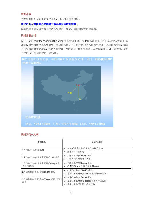
视频背景介绍iMC (Intelligent Management Center )智能管理平台,是iMC 智能管理中心的基础业务管理平台,在完成网络和用户基本资源统一管理的基础之上,提供融合的基础网络管理。
基础网络管理,涵盖了传统网管的主要功能,包括告警管理、性能管理、拓扑管理等。
本视频案例以M 公司为例,介绍了使用iMC 管理网络的一般步骤。
视频案例一览表 案例名称关键点说明 1.1准备工作-启动iMC z在H3C 部署监控代理中启动iMC 服务 z查看进程启动状态 1.2准备工作-在设备上配置SNMP 参数 z了解配置哪些SNMP 参数 z了解参数之间的对应关系 1.3准备工作-在设备上配置Syslog 参数(可选配置) z了解配置哪些Syslog 参数 z在iMC Syslog 管理中浏览Syslog 2.1添加网络资源-增加SNMP 模板 z在iMC 中增加SNMP 模板 z与在设备上所配置SNMP 参数的对应关系 2.2添加网络资源-增加Telnet 模板(可选配置)z在iMC 中增加Telnet 模板 z与在设备上所配置Telnet 参数的对应关系 z 在自动发现中如何引用该模板2.3添加网络资源-自动发现z通过自动发现中的网段方式向iMC中批量增加设备z自动发现结果展示z接入设备与核心设备的配置3.1规划网络-增加设备分组z增加设备分组的过程3.2规划网络-增加自定义分组视图z增加自定义分组视图的过程3.3规划网络-为各区域操作员分配权限z增加各区域的操作员z将某一区域的操作员与管理的设备分组和自定义分组进行关联3.4规划网络-拓扑调整z网络拓扑视图操作:增加视图、增加背景图以及创建子图z自定义视图操作:自动连接、查看链路信息、手工增加链路3.5规划网络-修改设备标签z修改设备标签3.6规划网络-第三方设备识别z增加设备厂商z增加设备系列z增加设备型号4.1维护网络-性能监视z增加监视z查看性能视图4.2维护网络-告警转发设置z邮件告警转发设置4.3维护网络-设备配置管理操作演示z设置文件传输方式z手工备份设备配置z导入设备软件z定制自动备份计划4.4维护网络-单台设备常用操作演示z拓扑定位z打开设备面板z修改系统组属性z更改基础性能监视项z环境监控z VLAN接口管理4.5维护网络-批量操作z批量配置Telnet参数z校验Telnet参数z批量保存设备配置5.1周期报表-增加及查看周期报表z增加周期报表z查看周期报表Copyright ©2009 杭州华三通信技术有限公司版权所有,保留一切权利。
Z CAM IPMAN S 无线视频流传输设备快速用户指南说明书

Z CAM Monitor (App Store)Z Camera (Google Play)Z CAM IPMAN S Wireless Video Streaming Device - Quick User Guide What is in the box?●Z CAM IPMAN S main unit x 1.●Wi-Fi antenna x 2.How to power up Z CAM IPMAN S?●Mount NP-F battery on to the rear socket of the main unit.●Press and hold the release button next to the socket to unmount the battery.●For external power supply, connect the DC plug to the power socket (6.2~18V) on the side.How to switch on Z CAM IPMAN S?●Ensure that power is connected.●Push power switch upward to ON position to switch on.●Push power switch downward to OFF position to switch off.How to feed video signal to the HDMI input of Z CAM IPMAN S?●Connect HDMI output of camera or other equipment to HDMI IN of the main unit.How to get video signal from the HDMI output of Z CAM IPMAN S?●Connect HDMI input of monitor or other equipment to HDMI OUT of the main unit.How to install WiFi antenna?●Align the bottom of the antenna and the antenna port on top of the main unit.●Screw in the antenna clockwise until it is fixed in position.●Both antennas need to be installed.How to switch the operating mode of Z CAM IPMAN S?●Mode selector on the side of the main unit set to Rx, status display will change to RX.●Mode selector on the side of the main unit set to M, status display will change to TX-P.●Mode selector on the side of the main unit set to Tx, status display will change to TX.How to use wireless video monitoring feature?●Camera HDMI output signal must be 1080p60 or below(1080i is not supported).●Connect camera HDMI output to HDMI IN of main unit,set to TX mode.●Set another main unit to RX mode, connect HDMI OUT to monitor input.●Press and hold the function button in the middle for two second until pairing icon shows up.●Release the function button and wait for auto pairing.●Channel number on both units should be the same once pairing is successful.●Once there is a camera HDMI signal output it will be streamed to the RX connected monitor.●Repeat above procedure to add RX main unit up to a maximum of four.How to use mobile devices for video monitoring?●Download and install “Z CAM Monitor” app on iOS devices.(use Z Camera app on Android devices)●Camera HDMI output signal must be 1080p60 or below(1080i not supported).●Connect camera HDMI output to HDMI IN of main unit,set to TX mode.●Note the SSID on the top left corner of main unit display.●Open “Z CAM Monitor” app, click the bottom right wireless hotspot icon, enter SSID and tap the arrow sign to connect.●Once there is a camera HDMI signal output it will be streamed to the“Z CAM Monitor”app.●Repeat above procedure to add mobile devices up to a maximum of four.How to connect to a wireless router?(* This feature is not yet supported on Android.)●Select M mode on the main unit.●Connect iOS device to main unit using USB-C to Lightning cable.●Turn on the main unit and iOS device, open the Z CAM Monitor app.●Tap the bottom right wireless network icon. Available wireless networks will be shown.●Select the wireless network, enter password and and tap the arrow sign to connect.●Connected WiFi SSID and IP address will be shown on the main unit display.Please visit for latest product information and user guide.Disclaimer: All product features and technical specifications stated are subjected to the sole interpretation and explanation of Shenzhen ImagineVision Technology Limited.。
HCiMC设备管理之大屏展示区域地图绘制典型配置

H3C iMC设备管理之大屏展示区域地图绘制典型配置案例一、组网需求:传统的网络管理软件,可以通过网络拓扑展现被管理设备的运行状态,H3C iMC (智能管理中心)除了支持丰富IP拓扑、二层拓扑、机房拓扑、虚拟网络拓扑外,从iMC PLAT 5.1(E0201L03)版本开始,还新增了大屏监视功能,在特定分辨率的大屏显示器/投影中,图形化展示用户关心的各类业务的实时运行状态,各类数据的多维度展示为客户的分析及运营决策提供支持。
用户可灵活配置业务部件的位置、大小,其中区域地图可自行定义,可根据客户的实际网络架构及节点分布,将关注的网络设备、拓扑布局在区域地图对应的位置,让网络管理人员能直观掌握各区域设备的运行状态。
二、配置步骤:1、绘制区域地图1.1、运行imc-tools工具,该工具在iMC PLAT安装包下的tools文件夹内,双击imc-tools.exe打开“大屏背景绘制工具”操作界面,如下图所示:(1)运行前imc-tools前,需要先在本机安装Java 6 或 7。
(2)只有iMC PLAT V5.2安装包下有imc_tool.exe工具,PLAT V5.1、PLAT V7安装包下面都没有(后续会在PLAT V7补丁合入)。
该工具绘制出来的区域地图和iMC PLAT版本没有配套关系,即使用V5.2安装包下的工具绘制出来的区域地图可以在iMC V5.1和iMC V7平台使用。
1.2、点击工具栏的“使用图片背景”菜单导入背景图片,并使用描点工具描点区域,如下图所示:使用描点工具对照背景图进行描点,完成描点后,删除背景图,如下图所示。
右击对应的Node区域,可修改对应区域的名称,例如上图所示。
1.3、点击工具栏的“发布工程”菜单发布工程文件,并保存,如下图所示:发布的工程文件名不能使用非ASCALL码,否则无法导入到iMC。
2、导入定制的区域地图模板到iMC2.1、定制的区域地图导入到iMC大屏监视框架,点击“导航栏”图标>>“大屏监视”>>“配置”按钮,如下图所示:选择“区域地图”图标,并拖拽到布局版,具体布局位置和大小根据实际情况调整,如上图所示。
iMC APM 使用APM监视MySQL应用配置举例

使用APM监视MySQL应用配置举例产品版本:iMC APM 7.3 (E0504)Copyright © 2017 新华三通信技术有限公司版权所有,保留一切权利。
非经本公司书面许可,任何单位和个人不得擅自摘抄、复制本文档内容的部分或全部,并不得以任何形式传播。
本文档中的信息可能变动,恕不另行通知。
目录1 特性介绍 (1)2 特性使用指南 (1)2.1 适用场合 (1)2.2 配置前提 (1)3 配置举例 (1)3.1 组网需求 (1)3.2 配置步骤 (2)3.2.1 增加MySQL监视 (2)3.2.2 配置MySQL监视全局阈值 (4)3.3 配置验证 (5)3.3.1 查看MySQL应用监控报表 (5)1 特性介绍MySQL是一个关系型数据库管理系统(RDBMS)。
APM可监控的MySQL版本包括MySQL 5.x。
本文将对APM监控MySQL 5.5.28的配置过程和监视报表进行介绍。
2 特性使用指南2.1 适用场合本文主要用于介绍APM在数据中心环境下MySQL应用的监视。
2.2 配置前提•MySQL配置、部署和启动正常。
•APM服务器安装和部署完成,并且可以和MySQL之间正常通信。
•只有在APM中配置了流量采集器,应用报表中流量相关的数据才会显示。
3 配置举例3.1 组网需求某公司数据中心有台MySQL数据库服务器,专为企业提供数据库管理服务,如图1所示。
服务器管理员现在要使用iMC APM对MySQL服务器进行监视,组网明细如表1所示。
图1 组网图表1 组网明细主机名IP 地址应用用途NMS 172.50.2.139 • Windows Server 2008 R2• iMC PLAT 7.3 (E0506)• iMC APM 7.3 (E0501)网管系统(集中式部署)Host 192.168.7.205• Windows Server 2012 •MySQL_5.5.28提供数据库管理服务3.2 配置步骤3.2.1 增加MySQL 监视(1) 登录iMC 控制台。
H3C-IMC安装指导

Copyright © 2007-2010 杭州华三通信技术有限公司及其许可者 版权所有,保留一切权利。 未经本公司书面许可,任何单位和个人不得擅自摘抄、复制本书内容的部分或全部,并不得以任何 形式传播。
H3C、
读者对象
本手册主要适用于如下工程师: z 网络规划人员 z 现场技术支持与维护人员 z 负责网络配置和维护的网络管理员
本书约定
1. 图形界面格式约定
格式
意义
<>
带尖括号“< >”表示按钮名,如“单击<确定>按钮”。
[]
带方括号“[ ]”表示窗口名、菜单名和数据表,如“弹出[新建用户]窗口”。
i
格式 /
如果您在使用过程中发现产品资料的任何问题,可以通过以下方式反馈: E-mail:info@ 感谢您的反馈,让我们做得更好!
ii
目录
1 概述 ................................................................................................................................................... 2-1 1.1 iMC组成介绍 ..................................................................................................................................... 2-1 1.2 iMC版本介绍 ..................................................................................................................................... 2-1
MINI 6 CHANNEL MULTI-FORMAT 视频交换器用户手册说明书

CONTENTS
1. BRIEF INTRODUCTION...............................................................................................................................2 1.1. Overview...................................................................................................................................................... 2 1.2. Main Features............................................................................................................................................. 2 2. INTERFACES................................................................................................................................................. 3 2.1. Rear Interfaces.......................
IMC智能管理中心操作手册v1

目录1 前提说明 (3)2 IMC系统配置 (3)2.1 系统登陆 (3)2。
2 SNMP模板配置 (4)2。
3 T ELNET模板配置 (5)2.4 报警服务器配置 (7)2。
4.1 Mail报警配置 (7)2。
5 设备分组配置 (8)2。
6 系统用户配置 (9)2。
6。
1 访问控制模板配置 (9)2。
6.2 操作员配置 (10)2.6。
3 在线操作员操作 (15)3 IMC资源配置 (15)3.1 新增设备配置 (16)3。
2 IMC性能配置及监控 (18)3.3 设备导入导出配置 (19)3.4 拓扑导入导出配置 (21)4 IMC业务配置 (22)4。
1 接入设备配置 (22)4。
2 服务配置管理配置 (25)4.3 接入时段策略管理配置 (28)4。
4 P ORTAL服务管理配置 (30)4。
4。
1 服务器配置 (31)4.4。
2 设备配置 (32)4.4.3 IP地址组配置 (34)4.4.4 启用Portal服务管理配置 (36)4。
5 设备配置管理 (36)4。
5.1 自动备份计划操作配置 (36)4。
5。
1.1 ............................................................................................................. 自动备份计划配置操作364.5。
1.2 自动备份计划立即备份操作 (39)4。
5.1。
3 .....................................................................................................................查看设备配置信息414。
5。
1。
4 ..................................................................................................................查看设备配置校验444.5。
iMC安装
iMC安装指导文档目录目录iMC安装指导文档 (1)1概述 (2)1.1安装部署 (2)1.2安装日志 (2)1.3安装环境 (2)1.4小结 (2)2数据库安装 (3)3iMC平台安装 (3)3.1Windows下集中式本地数据库安装 (3)3.2启动iMC服务 (10)3.3浏览器登陆 (12)4Linux下安装iMC平台 (13)4.1Linux下主服务器安装iMC (13)4.2Linux从服务器安装iMC (22)4.3Linux下卸载iMC平台 (28)5安装中遇到的问题 (30) Framework 2.0 SP2未安装 (30)1 概述1.1 安装部署iMC为了提高服务器的使用性能,采用了“安装+部署”的安装策略。
安装:是将iMC平台或业务组件拷贝到一台服务器上,并加载到智能监控代理中。
部署:是将iMC平台或业务组件在服务器上进行解压、创建数据库脚本等操作。
iMC支持集中式和分布式安装部署。
iMC集中式安装部署是将所有的业务组件和平台一起安装部署在同一台服务器上;iMC分布式安装部署是为实现负载均衡,将平台和业务组件安装在不同的服务器上,其中安装平台和必要组件的服务器称为主服务器,安装业务组件的服务器称为从服务器。
1.2 安装日志安装过程中产生的日志文件位于C:\Windows\iMC-Reserved\log,linux下位于/etc/iMC-Reserved/log。
1.3 安装环境iMC对硬件和软件的支持要求具体参考各版本自带官方说明文档,以符合客户的实际业务需求和现有设备资产条件。
本次安装说明文档专注于安装过程。
在Windows和Linux下分别支持SQL Server和Oracle数据库。
本次分别采用Windows Server 2012 x64中文版, SQL Server 2012,iMC V7.1 E0303标准版集中式本地数据库安装;和RHEL6.1 i386英文版, Oracle 11G R2, iMC V7.1 E0302专业版分布式本地数据库安装,和分布式远程安装。
iMC平台产品自定义性能监视指标功能的配置[技巧]
![iMC平台产品自定义性能监视指标功能的配置[技巧]](https://img.taocdn.com/s3/m/46f8805803768e9951e79b89680203d8cf2f6a70.png)
iMC平台产品自定义性能监视指标功能的配置[技巧] iMC平台产品自定义性能监视指标功能的配置一、组网需求:当iMC预定义的监视指标不满足现场网管需求时,iMC支持自定义性能监视指标。
比如要监视第三方设备的CPU,但该设备的CPU对应的MIB节点为私有MIB节点,在iMC中未定义,可以通过此功能实现对第三方设备的CPU监视。
二、组网图:无三、配置步骤:登录iMC界面,点击【资源】|【性能管理】|【全局指标设置】。
在该页面点击【增加自定义性能指标】进入设置界面。
图1 自定义监视设置界面参数说明如下:指标公式: 某些性能监视指标为多个OID的运算结果,这种情况下,需要通过Formula进行组合运算。
增加监视或测试时,iMC获取公式中OID的所有实例(例如设备的所有接口),实例的索引格式在Type中定义,实例的索引描述通过索引描述OID中设定的OID获取。
索引描述OID:通过设定的OID将实例的索引转换为便于识别的字符串形式,比如Ethernet1/0/1。
可以直接点击Select OID按钮,通过iMC MIB管理工具进行选择。
索引类型: 用来表示监控实例在MIB定义中的索引格式,支持多级。
[index1[0|2]:NAME:TYPE:LENGTH].[index2[0|2]:NAME:TYPE:LENGTH]index1、index2:仅在定义时作为标识,没有实际意义[0|2]:0表示索引属于非表节点对象,2表示索引属于表节点对象NAME:实际显示出来的监控实例名称TYPE:索引的数值类型,1为Integer;2为StringLENGTH:索引的长度,对于TYPE为Integer或单级索引,取0示例:[index1[2]:Interface:1:0][index1[2]:Frame:1:0].[index2[2]:Slot:1:0].[index3[2]:Memory:1:0]以自定义“接口接收速率测试指标”为例,配置步骤如下:1、定义公式。
PIVS-6-100 6mm手动推进视频探头系统说明书

Portable push camera system with a 6mm diameter tip and a long 100 foot insertion probe. The video camera head is flexible and is supplied with bright LED lighting. Ideal for pipelines, ducts, drains or sewer inspections.
The push camera head contains 12 adjustable LED lights, a flexible spring coiled joint to navigate around corners, and a Sapphire lens to resist scratching. This high resolution pipe inspection camera is designed to capture bright, crisp, color video of the inspection area. An optional 512Hz frequency sonde, located immediately behind the camera head, with the ability to remotely locate it (with the use of the optional locator). The monitor and additional controls are built into a compact, waterproof and lightweight hard plastic case making it easy to transport. The 7” TFT LCD color display presents a live color image with your thumb drive. An adjustable sun hood is included as a sun shield for outdoor inspections.
- 1、下载文档前请自行甄别文档内容的完整性,平台不提供额外的编辑、内容补充、找答案等附加服务。
- 2、"仅部分预览"的文档,不可在线预览部分如存在完整性等问题,可反馈申请退款(可完整预览的文档不适用该条件!)。
- 3、如文档侵犯您的权益,请联系客服反馈,我们会尽快为您处理(人工客服工作时间:9:00-18:30)。
查看方法
点击左侧的链接进入相关视频的介绍和下载页面。
下载并观看视频案例。
视频案例一览表
WSM组件简介WSM(Wireless Service Manager)结合智能管理平台(Intelligent Management Center,简称iMC)和智能配置中心(Intelligent Control Configuration,简称iCC),为WLAN 管理提供了一个完善的解决方案。
位置视图、分类视图、无线自定义视图、Rogue设备管理、策略模板管理、无线设备配置管理、配置向导、用户在线历史和无线业务报表等主要功能。
WSM案例名称关键点说明
01-AC+Fit AP无线网络配置案例z设置AC基本配置
z配置Radio策略
z配置无线逻辑接口
z配置服务策略
z批量配置Radio
z模拟用户登录并进行验证
02-Fat AP无线网络配置案例z配置BSS接口
z配置服务策略
z配置Radio参数
z确认创建的ESS信息
z模拟用户登录并进行验证
03-位置视图管理z增加位置视图
z将AP设备增加到位置视图中
z插入拓扑背景图,调整AP位置z查看AP的信号覆盖情况
z锁定AP位置,保存位置视图拓扑z查看指定AP的邻居拓扑
04-无线自定义视图管理z创建无线自定义视图
z查看无线自定义视图拓扑,并定位具体设备
05-无线报表生成与展示z Fat AP流量汇总报表生成展示z AP可用率汇总报表生成展示
z AP退服汇总报表生成展示
z移动用户在线趋势报表生成展示
06-无线设备拓扑管理z查看AC设备拓扑
z查看无线设备间的链路信息
z查看Fit AP的在线用户,并调整其在拓扑中的位置z查看移动用户的基本信息
z查看单个/多个Fit AP的物理拓扑
07- Fit AP分组管理z增加iMC操作员
z创建Fit AP分组,并指定可管理操作员z验证对Fit AP的分组授权是否成功
06-无线定位配置案例z采样用户设置
z确认位置视图中AP的参数设置z设置采样点采样
z移动用户定位
Copyright ©2009-2010 杭州华三通信技术有限公司版权所有,保留一切权利。
非经本公司书面许可,任何单位和个人不得擅自摘抄、复制本文档内容的部分或全部,并不得以任何形式传播。
本文档中的信息可能变动,恕不另行通知。
