Clear box 规格书
碳膜电阻(规格书)

第二条 2nd significant
0 1 2 3 4 5 6 7 8 9
倍数 Multiplier
0.01 0.1 1 10 100 1K 10K 100K 1M 10M
碳膜电阻:土黄色本体,涂四色环。
误差 Tolerance ±10%(K) ±5%( J)
±2%(G)
Page 7 of 15 CF
定格及尺寸specifications额定电力最高使用电压最高过负荷电压最高断续过负荷dimensionmmpowerrating70maximunworkingvoltagemaximunoverloadvoltagemaximuniintermittenceoverloadvoltage型号d005阻值范围resistncerange4632051803212004018w16w200v400v400v583202180228200404660052303212004014w12ws250v500v500v586005230327200405690053205222004512w1ws350v700v700v58900532052420045or050541151040052120050or060tb52581151040052520050or060or0701w2ws500v1000v1000vtb63721151045053020050or060or070581551055052020060or065tb63721551055052920060or0702w3ws500v1000v1000vtb7281155105053420060or0703w5ws500v1000v1000v9417510600538200700755w500v1000v1000v942451080053520070075standard151megspeciallow005high15cf项目item规格值specfications试验方法testmethodsjisc5202抵抗值dcresistance须在规定之r值的容许差内allowedunderratetolerance101mm101mm3502000抵抗温度特性tcrppm47k以下51k100k110k330k360k43m47m以上52测定条件25125testterms25125短时间过负载suorttimeoverload2005以内55定格电压25倍测试5秒permanentresistancechangeafter25timercwvseconds断续过负载intermittenceoverloadvoltage2005以内58定格电压秒关25秒反复10000resistancechangeafter25secondoff10000cyclestimesrc
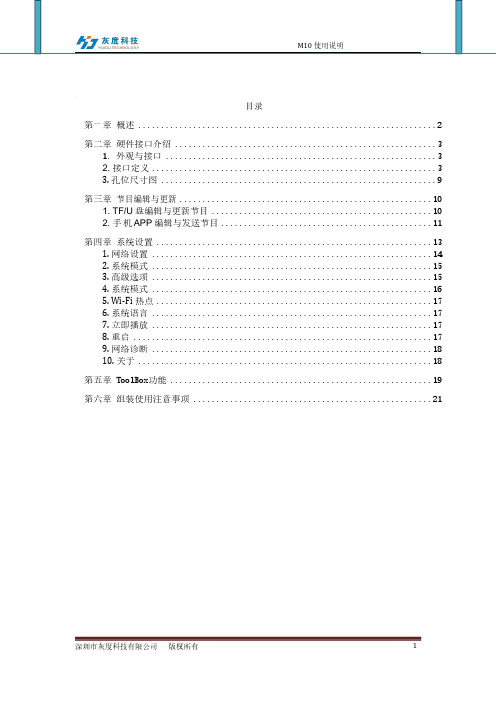
M10使用说明说明书
目录第一章概述 (2)第二章硬件接口介绍 (3)1. 外观与接口 (3)2. 接口定义 (3)3. 孔位尺寸图 (9)第三章节目编辑与更新 (10)1. TF/U 盘编辑与更新节目 (10)2. 手机APP 编辑与发送节目 (11)第四章系统设置 (13)1. 网络设置 (14)2. 系统模式 (15)3. 高级选项 (15)4. 系统模式 (16)5. Wi-Fi 热点 (17)6. 系统语言 (17)7. 立即播放 (17)8. 重启 (17)9. 网络诊断 (18)10. 关于 (18)第五章 ToolBox功能 (19)第六章组装使用注意事项 (21)第一章概述M10采用瑞芯微RK3188 四核芯片方案,使用Android4.4.4系统。
RK3188 采用ARM 四核A9 内核芯片、GPU 采用Mali-400 系列, 跑分最高达22000多分超强性能,支持主流音视频格式和图片的解码。
双路LVDS 接口,支持1080P 输出,支持HDMI 接口1080P 输出,支持2K 级的视频播放。
支持红外遥控器,Wi-Fi,RJ45 等丰富的接口,让产品变得更加通用,被广泛的应用到广告机、互动一体机、安防、医疗、交通、金融、工控等等智能控制领域。
由于其硬件平台化、Android 智能化的特点,在需要进行人机交互,网络设备交互时,都可以在智能终端主板上进行使用。
产品特点:➢高性能,RK3188芯片采用四核ARM Cortex A9 架构,采用了该芯片的RK3188 主板方案,对比市面常见的单核、双核、四核方案,在性能上有质的飞跃,能够播放各种格式高清视屏,能处理复杂的互动操作;➢高稳定性,M10在硬件、软件上,增加自己独有的技术来保证产品的稳定性,可以使最终产品达到7*24 小时无人值守;➢高集成度,M10集成了以太网、Wi-Fi、功放、TF 扩展卡、USB 扩展口、IR 遥控功能、HDMI、LVDS、背光控制、麦克风等功能,大大简化了整机设计;➢高扩展性,四个扩展USB 口,3路串口+1路可扩展调试串,一个I2C 接口,五个IO 扩展口能扩展更多的外设设备。
电缆常用中英文对照

一、 COLOR TYPE<颜色类〉Black〈黑色〉 Brown〈棕色〉 Yellow<黄色〉 Green〈绿色>White〈白色> Gray/Grey〈灰色〉 Red〈红色〉 Orange〈橙色>Blue<蓝色〉 Pink<粉红色> Purple/Violet<紫色〉Beige〈贝吉色> Ivory〈象牙色> Frost White〈霜白〉 Light Green〈浅绿色〉二、Month Type〈月份类>January 一月 February 二月 March 三月April 四月 May 五月 June 六月July 七月 August 八月 September 九月October 十月 November 十一月 December 十二月三、Week Type<星期类>Monday星期一 Tuesday星期二 Wednesday星期三Thursday星期四 Friday星期五 Saturday星期六Sunday星期日铜包铝镁英文全称:Copper clad aluminum magnesium wire四、Length Type<长度类〉1foot<英尺>=12inches<英寸〉=0.3048meter<米>1yard<码〉=3feet<英尺〉=0。
9144meter〈米〉1mile〈英里〉=1760yards<码〉=1.609kilometers〈千米〉1meter〈米〉=10dm<分米>=1。
0936yards〈码>=3。
2808<英尺>1centimeter〈厘米>=10mm<亳米〉=0。
3937inch<英寸>五、Cable Type〈电线类>Cable〈电缆线> Jacket〈外被〉 Conductor<导体/芯线〉 Braid<编织〉 Spiral〈缠绕〉Drain Wire<地线〉 Al-Foil/Mylar<铝箔/麦拉〉 Paper<包纸〉 P-P—Foamed〈发泡P。
1554J2GY,1554J2GYSL,1554J2GYCL,1554JGY,1554JPL, 规格书,Datasheet 资料

81.00 mm [3.189 in]
24.00 mm [0.945 in] M3 - 0.5 BRASS INSERTS 4X
n3.00 mm 4X
A
135.88 mm [5.350 in] 147.00 mm [5.787 in]
[0.118 in]
132.00 mm [5.197 in] Poured Silicone Gasket Loctite 5950 Material
8
7
6
5
4
3
2
1
160.00 mm [6.299 in]
D
A
60.00 mm [2.362 in] D
B
B
File #E65324 NEMA 4, 4X
90.00 mm [3.543 in]
A ASSEMBLY
C 154.88 mm [6.098 in]
SECTION A-A
n3.73ቤተ መጻሕፍቲ ባይዱmm 4X
147.32 mm [5.800 in] 121.46 mm [4.782 in]
NOTE
Purchased assembly includes box, lid, and 4 cover screws Recommended Cover screw torque -- 2.5 lbf-in (30 cN-m) Polycarbonate version is UL 508 approved Matl UL94 - V0 / 5VA @ 3mm
C
[0.147 in]
54.00 mm [2.126 in]
6.00 mm [0.236 in]
46.37 mm [1.826 in]
包装规格书通用版V1
B.变更履历 (History of Document)
■新增
□ 改版
□作废
Revision No.
版本号
Revision 变更内容
A0
初版
Reason 变更原因
---------
Sign. 签名
Date 日期
深圳欧菲光科技股份有限公司
SHENZHEN O-FILM TECH.CO.,LTD
C.内容说明(Assembly Explain):
深圳欧菲光科技股份有限公司
SHENZHEN O-FILM TECH.CO.,LTD
A.基本内容说明 (Specification Base Explain)
Model NO
Panel Size
”
Type
C-TP
Transport
Pannel Dimension
FPC Dimension
Version 1.0 NA
内容 Contents
备注 Remark
包装盒面积最大面从 80 cm 高度跌落两次(正反面各一 此项目仅为一般测试,若
次),产品不破损。
客户有特殊要求,我们将
No damage to the product when the biggest side of 针对不同厚度的产品进行
package drops about 2 times. from 80 cm height (each in 测试。 upper and bottom surface).
阻抗应介于 106~1011Ω 之间
MA
五、包装步骤(Package Process)
1、按《包装来料检验标准》检查tray是否有不良(包括破损,变形等等); 2、将清洁后的成品放置于 tray 内,以产品的侧边靠着包装的一边,产品正面朝下 平放,注意 FPC 的方向;
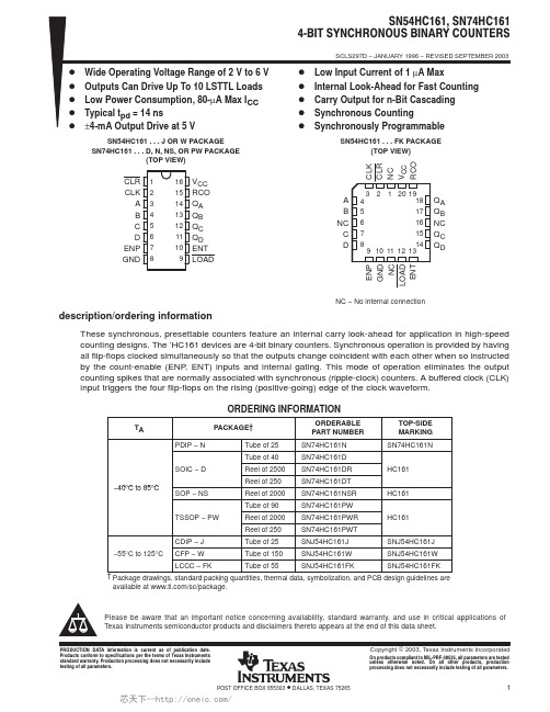
SN74HC161N,SN74HC161NSR,SN74HC161PWT,SN74HC161DRE4,SN74HC161DRG4,SN74HC161PWR, 规格书,Datasheet 资料
Addendum-Page 1PACKAGING INFORMATIONOrderable Device Status(1)Package Type PackageDrawingPins Package QtyEco Plan(2)Lead/Ball FinishMSL Peak Temp (3)Samples (Requires Login)5962-8407501VEA ACTIVE CDIP J 1625TBD A42N / A for Pkg Type 5962-8407501VFAACTIVE CFP W 1625TBD A42N / A for Pkg Type 84075012A ACTIVE LCCC FK 201TBD Call TI Call TI 8407501EA ACTIVE CDIP J 161TBD Call TI Call TI 8407501FA ACTIVE CFP W 161TBD Call TI Call TIJM38510/66302BEA ACTIVE CDIP J 161TBD A42N / A for Pkg Type JM38510/66302BFA ACTIVE CFP W 161TBD A42N / A for Pkg Type M38510/66302BEA ACTIVE CDIP J 161TBD A42N / A for Pkg Type M38510/66302BFA ACTIVE CFP W 161TBD A42N / A for Pkg Type SN54HC161J ACTIVE CDIP J 161TBDA42N / A for Pkg TypeSN74HC161D ACTIVE SOIC D 1640Green (RoHS & no Sb/Br)CU NIPDAU Level-1-260C-UNLIM SN74HC161DE4ACTIVE SOIC D 1640Green (RoHS & no Sb/Br)CU NIPDAU Level-1-260C-UNLIM SN74HC161DG4ACTIVE SOIC D 1640Green (RoHS & no Sb/Br)CU NIPDAU Level-1-260C-UNLIM SN74HC161DR ACTIVE SOIC D 162500Green (RoHS & no Sb/Br)CU NIPDAU Level-1-260C-UNLIM SN74HC161DRE4ACTIVE SOIC D 162500Green (RoHS & no Sb/Br)CU NIPDAU Level-1-260C-UNLIM SN74HC161DRG4ACTIVE SOIC D 162500Green (RoHS & no Sb/Br)CU NIPDAU Level-1-260C-UNLIM SN74HC161DT ACTIVE SOIC D 16250Green (RoHS & no Sb/Br)CU NIPDAU Level-1-260C-UNLIM SN74HC161DTE4ACTIVE SOIC D 16250Green (RoHS & no Sb/Br)CU NIPDAU Level-1-260C-UNLIM SN74HC161DTG4ACTIVE SOIC D 16250Green (RoHS & no Sb/Br)CU NIPDAU Level-1-260C-UNLIM SN74HC161N ACTIVE PDIP N 1625Pb-Free (RoHS)CU NIPDAU N / A for Pkg Type SN74HC161N3OBSOLETE PDIP N 16TBD Call TICall TISN74HC161NE4ACTIVEPDIPN1625Pb-Free (RoHS)CU NIPDAU N / A for Pkg Type芯天下--/Addendum-Page 2Orderable Device Status(1)Package Type PackageDrawingPins Package QtyEco Plan(2)Lead/Ball FinishMSL Peak Temp(3)Samples (Requires Login)SN74HC161NSR ACTIVE SO NS 162000Green (RoHS & no Sb/Br)CU NIPDAU Level-1-260C-UNLIM SN74HC161NSRE4ACTIVE SO NS 162000Green (RoHS & no Sb/Br)CU NIPDAU Level-1-260C-UNLIM SN74HC161NSRG4ACTIVE SO NS 162000Green (RoHS & no Sb/Br)CU NIPDAU Level-1-260C-UNLIM SN74HC161PW ACTIVE TSSOP PW 1690Green (RoHS & no Sb/Br)CU NIPDAU Level-1-260C-UNLIM SN74HC161PWE4ACTIVE TSSOP PW 1690Green (RoHS & no Sb/Br)CU NIPDAU Level-1-260C-UNLIM SN74HC161PWG4ACTIVE TSSOP PW 1690Green (RoHS & no Sb/Br)CU NIPDAU Level-1-260C-UNLIM SN74HC161PWR ACTIVE TSSOP PW 162000Green (RoHS & no Sb/Br)CU NIPDAU Level-1-260C-UNLIM SN74HC161PWRE4ACTIVE TSSOP PW 162000Green (RoHS & no Sb/Br)CU NIPDAU Level-1-260C-UNLIM SN74HC161PWRG4ACTIVE TSSOP PW 162000Green (RoHS & no Sb/Br)CU NIPDAU Level-1-260C-UNLIM SN74HC161PWT ACTIVE TSSOP PW 16250Green (RoHS & no Sb/Br)CU NIPDAU Level-1-260C-UNLIM SN74HC161PWTE4ACTIVE TSSOP PW 16250Green (RoHS & no Sb/Br)CU NIPDAU Level-1-260C-UNLIM SN74HC161PWTG4ACTIVE TSSOP PW 16250Green (RoHS & no Sb/Br)CU NIPDAU Level-1-260C-UNLIM SNJ54HC161FK ACTIVE LCCC FK 201TBD POST-PLATE N / A for Pkg TypeSNJ54HC161J ACTIVE CDIP J 161TBD A42N / A for Pkg Type SNJ54HC161WACTIVECFPW161TBDA42N / A for Pkg Type(1)The marketing status values are defined as follows:ACTIVE: Product device recommended for new designs.LIFEBUY: TI has announced that the device will be discontinued, and a lifetime-buy period is in effect.NRND: Not recommended for new designs. Device is in production to support existing customers, but TI does not recommend using this part in a new design.PREVIEW: Device has been announced but is not in production. Samples may or may not be available.OBSOLETE: TI has discontinued the production of the device.芯天下--/(2) Eco Plan - The planned eco-friendly classification: Pb-Free (RoHS), Pb-Free (RoHS Exempt), or Green (RoHS & no Sb/Br) - please check /productcontent for the latest availability information and additional product content details.TBD: The Pb-Free/Green conversion plan has not been defined.Pb-Free (RoHS): TI's terms "Lead-Free" or "Pb-Free" mean semiconductor products that are compatible with the current RoHS requirements for all 6 substances, including the requirement that lead not exceed 0.1% by weight in homogeneous materials. Where designed to be soldered at high temperatures, TI Pb-Free products are suitable for use in specified lead-free processes.Pb-Free (RoHS Exempt): This component has a RoHS exemption for either 1) lead-based flip-chip solder bumps used between the die and package, or 2) lead-based die adhesive used between the die and leadframe. The component is otherwise considered Pb-Free (RoHS compatible) as defined above.Green (RoHS & no Sb/Br): TI defines "Green" to mean Pb-Free (RoHS compatible), and free of Bromine (Br) and Antimony (Sb) based flame retardants (Br or Sb do not exceed 0.1% by weight in homogeneous material)(3) MSL, Peak Temp. -- The Moisture Sensitivity Level rating according to the JEDEC industry standard classifications, and peak solder temperature.Important Information and Disclaimer:The information provided on this page represents TI's knowledge and belief as of the date that it is provided. TI bases its knowledge and belief on information provided by third parties, and makes no representation or warranty as to the accuracy of such information. Efforts are underway to better integrate information from third parties. TI has taken and continues to take reasonable steps to provide representative and accurate information but may not have conducted destructive testing or chemical analysis on incoming materials and chemicals. TI and TI suppliers consider certain information to be proprietary, and thus CAS numbers and other limited information may not be available for release.In no event shall TI's liability arising out of such information exceed the total purchase price of the TI part(s) at issue in this document sold by TI to Customer on an annual basis.OTHER QUALIFIED VERSIONS OF SN54HC161, SN54HC161-SP, SN74HC161 :•Catalog: SN74HC161, SN54HC161•Military: SN54HC161•Space: SN54HC161-SPNOTE: Qualified Version Definitions:•Catalog - TI's standard catalog product•Military - QML certified for Military and Defense Applications•Space - Radiation tolerant, ceramic packaging and qualified for use in Space-based applicationAddendum-Page 3芯天下--/TAPE AND REEL INFORMATION*All dimensions are nominalDevicePackage Type Package Drawing Pins SPQReel Diameter (mm)Reel Width W1(mm)A0(mm)B0(mm)K0(mm)P1(mm)W (mm)Pin1Quadrant SN74HC161DR SOIC D 162500330.016.4 6.510.3 2.18.016.0Q1SN74HC161NSR SO NS 162000330.016.48.210.5 2.512.016.0Q1SN74HC161PWR TSSOP PW 162000330.012.4 6.9 5.6 1.68.012.0Q1SN74HC161PWTTSSOPPW16250330.012.46.95.61.68.012.0Q1*All dimensions are nominalDevice Package Type Package Drawing Pins SPQ Length(mm)Width(mm)Height(mm) SN74HC161DR SOIC D162500333.2345.928.6 SN74HC161NSR SO NS162000367.0367.038.0 SN74HC161PWR TSSOP PW162000367.0367.035.0SN74HC161PWT TSSOP PW16250367.0367.035.0IMPORTANT NOTICETexas Instruments Incorporated and its subsidiaries(TI)reserve the right to make corrections,enhancements,improvements and other changes to its semiconductor products and services per JESD46C and to discontinue any product or service per JESD48B.Buyers should obtain the latest relevant information before placing orders and should verify that such information is current and complete.All semiconductor products(also referred to herein as“components”)are sold subject to TI’s terms and conditions of sale supplied at the time of order acknowledgment.TI warrants performance of its components to the specifications applicable at the time of sale,in accordance with the warranty in TI’s terms and conditions of sale of semiconductor products.Testing and other quality control techniques are used to the extent TI deems necessary to support this warranty.Except where mandated by applicable law,testing of all parameters of each component is not necessarily performed.TI assumes no liability for applications assistance or the design of Buyers’products.Buyers are responsible for their products and applications using TI components.To minimize the risks associated with Buyers’products and applications,Buyers should provide adequate design and operating safeguards.TI does not warrant or represent that any license,either express or implied,is granted under any patent right,copyright,mask work right,or other intellectual property right relating to any combination,machine,or process in which TI components or services are rmation published by TI regarding third-party products or services does not constitute a license to use such products or services or a warranty or endorsement e of such information may require a license from a third party under the patents or other intellectual property of the third party,or a license from TI under the patents or other intellectual property of TI.Reproduction of significant portions of TI information in TI data books or data sheets is permissible only if reproduction is without alteration and is accompanied by all associated warranties,conditions,limitations,and notices.TI is not responsible or liable for such altered rmation of third parties may be subject to additional restrictions.Resale of TI components or services with statements different from or beyond the parameters stated by TI for that component or service voids all express and any implied warranties for the associated TI component or service and is an unfair and deceptive business practice. TI is not responsible or liable for any such statements.Buyer acknowledges and agrees that it is solely responsible for compliance with all legal,regulatory and safety-related requirements concerning its products,and any use of TI components in its applications,notwithstanding any applications-related information or support that may be provided by TI.Buyer represents and agrees that it has all the necessary expertise to create and implement safeguards which anticipate dangerous consequences of failures,monitor failures and their consequences,lessen the likelihood of failures that might cause harm and take appropriate remedial actions.Buyer will fully indemnify TI and its representatives against any damages arising out of the use of any TI components in safety-critical applications.In some cases,TI components may be promoted specifically to facilitate safety-related applications.With such components,TI’s goal is to help enable customers to design and create their own end-product solutions that meet applicable functional safety standards and requirements.Nonetheless,such components are subject to these terms.No TI components are authorized for use in FDA Class III(or similar life-critical medical equipment)unless authorized officers of the parties have executed a special agreement specifically governing such use.Only those TI components which TI has specifically designated as military grade or“enhanced plastic”are designed and intended for use in military/aerospace applications or environments.Buyer acknowledges and agrees that any military or aerospace use of TI components which have not been so designated is solely at the Buyer's risk,and that Buyer is solely responsible for compliance with all legal and regulatory requirements in connection with such use.TI has specifically designated certain components which meet ISO/TS16949requirements,mainly for automotive ponents which have not been so designated are neither designed nor intended for automotive use;and TI will not be responsible for any failure of such components to meet such requirements.Products ApplicationsAudio /audio Automotive and Transportation /automotiveAmplifiers Communications and Telecom /communicationsData Converters Computers and Peripherals /computersDLP®Products Consumer Electronics /consumer-appsDSP Energy and Lighting /energyClocks and Timers /clocks Industrial /industrialInterface Medical /medicalLogic Security /securityPower Mgmt Space,Avionics and Defense /space-avionics-defense Microcontrollers Video and Imaging /videoRFID OMAP Mobile Processors /omap TI E2E Community Wireless Connectivity /wirelessconnectivityMailing Address:Texas Instruments,Post Office Box655303,Dallas,Texas75265Copyright©2012,Texas Instruments Incorporated。
红光贴片LED-侧贴红光贴片LED灯珠规格书参数

承认书SPECIFICATION FOR APPROVAL 客户Customer:客户品号Customer P/N:鑫光硕品号Xgs Model:规格Specification :XGS-PB0802UE-02SMD 0805侧面红光普亮 20MA制作Prepared By:李忠审核Checked By:Customer Confirmation 客户确认采购部Pur Dept By品质部QA Dept By工程部Eng Dept By深圳市鑫光硕科技有限公司SHEN ZHEN XIN GUANG SHUO TECHNOLOGY CO.,LTD公司地址:广东省深圳市宝安区沙井万丰村前路31号8楼一厂地址:广东省深圳市龙岗区嶂背创业二路18-1号二厂地址:广东省东莞市石排镇庙边王村沙迳工业区Tel:Website :HData Sheet PN: XGS-PB0802UE-02 For:IF=20mAContents3.P ackage dimensions4.A bsolute maximum ratingoptical characteristics rangelabel pad dimensionsconditions10.Package tape specifications11.T ypical electro-optical characteristics curvestest items and conditions14.NotePart No.XGS-PB0802UE-02Emitted Color High Super Red Len's Color Water Clear Chip Material AlGaInP----◆Features:Compatible with automatic placementequipment Compatible with reflow solderprocessLow power consumption and wide viewing angleThis product doesn’t contain restriction Substance, comply ROHS standard.◆Applications:Automotive and TelecommunicationFlat backlight for LCD ,switch and symbol in telephone and faxGeneral use for indicators◆Package Dimensions:Unit:mmElectrodes: Ag Plating Tolerance±◆Absolute Maximum Rating (Ta=25℃)FP◆Electrical Optical Characteristics(Ta=25℃)Notes: of Luminous Intensity ±10%of Dominant Wavelength ±2nm3.Tolerance of Forward Voltage ±4.Luminous Intensity is measured by XGSLED’s equipment on bare chips3℃/sec.260℃ M ax. .210℃Pre-heating 120~160℃ 3℃/sec.-4℃/sec.60~120sec..◆ Soldering Pad Dimensions:◆ Soldering Conditions (Maximum allowable soldering conditions)Reflow soldering profile<Pb-free solder>Time• Reflow soldering should not be done more than two times. • Do not stress its resin while soldering.• After soldering,do not warp the circuit board.T e m p e r a t u r e225◆ Package Tape Specifications: ( 4000 pcs/Reel)Reel Lead No LEDs470225250603205 Reels in one Box 10 Boxes in one Carton◆ Typical Electro-Optical Characteristics Curves :Forward Current Vs Ambient Temperature5040302010200175 150 125107550 25 0 Forward Current Vs Relative Luminosity Ta=25℃2040608010010 20 30 40 50Ambient Temperature Ta (° C)Forward Current (mA)20015010050 Relative Luminosity VsAmbient TemperatureIf=15mA-50° -60°-70°-80°-90°-40°-30°-20°-10°0°10°20°30°40°50°60°70°80°90°0 020406080100Radiation AngleAmbient Temperature Ta (° C)R e l a t i v e L u m i n o s i t y (%)F o r w a r d C u r r e n t (m A )R e l a t i v e L u m i n o s i t y (%)◆Reliability(1)Test Items and Conditions(2)C riteria of judging the damage* Upper standard level Lower standard leve◆Cautions1、PackageWhen moisture is absorbed into the package it may vaporize and expand during soldering. There is apossibility that this can cause exfoliation of the contacts and damage to the optical characteristics of the LEDs. So the moisture proof package is used to keep moisture to a minimum in the package.2、StorageBefore opening the package: The LEDs should be kept at 5~30°C and 60%RH or less. The LEDs should be used within a year.After opening the package: The LED must be used within 24 hours, else should be kept at 5~30℃and 30% RH or less. The LEDs should be used within 7days after opening the package. If unused LEDs remain, they should be stored in moisture proof packages, recommended to return the LEDs to the original moisture proof bag and to reseal the moisture proof bag again.If the LEDs have exceeded the storage time, baking treatment should be performed more than 24hours at 60±5°C.3、Soldering IronEach terminal is to the tip of soldering iron temperature less than 300℃ for 3 seconds within once inless than the soldering iron capacity 25 two seconds and more internals, and do soldering of each terminal. Be careful because the damage of the product is often started at the time of the hand solder.4、RepairingRepairing should not be done after the LEDs have been soldered. When repairing is unavoidable, a double-head soldering iron should be used (as below figure). It should be confirmed beforehand whether thecharacteristics of the LEDs will or will not be damaged by repairing.5、The LED electrode sections are comprised of a gold plated. The gold surface may be affected by environments which contain corrosive gases and so on. Please avoid conditions which may cause the LED to corrode or discolor. This corrosion or discoloration may cause difficulty during soldering operations. It is recommended that the User use the LEDs as soon as possible.6、Please avoid rapid transitions in ambient temperature, especially in high humidity environmentswhere condensation can occur.◆Notes:1、Above specification may be changed without notice. We will reserve authority on material change for above specification.2 、 When using this product, please observe the absolute maximum ratings and the instructions for the specification sheets. We assume no responsibility for any damage resulting from use of the product which does not comply with the instructions included in the specification sheets.。
技术规格书(中英文)
技术规格书(中英⽂)NPC-National Petro Co.3600t Revolving/Engineering CraneTechnical Specification (Project Plan)Shanghai Zhenhua Port Machinery (Group) Co., Ltd.2005-12-10Table of Content1.1 General Description 总则1.1.1Consist of the Specification 本规格书组成The specification including general, hull structure, outfitting, machinery, electrical, refrigerating, air conditioning, ventilating, pipelaying, DP, and crane parts describes the 3600t CRANE PIPELAYING VESSEL based on scheme design.本规格书由船舶总体、舾装、轮机、电⽓、通风冷藏空调、动⼒定位、起重机及铺管设备估价等部分组成,表述3600 t全回转起重⼯程船的主要技术规格⽅案。
1.1.2Construction Explanation建造说明The BUILDER’s supply covers the item described in this specification, anything excluding from the scope of the specification will be supplied by the OWNER.本船的建造估价,所有规格书所规定的项⽬均由建造⽅提供。
超过规格书部分船东提供。
1.1.3Language and Measuring Unit⽂种与计量单位The drawings, instructions, instruments, display, caution sign and nameplate shall be written in English and kept down the foreign nameplate of the importation of machine and equipments. Metric system is used for designing and fabricating of hull, crane and equipment etc. unless otherwise specialized in specification or instruction.本船的图纸、使⽤说明书、仪表、显⽰、警⽰牌和铭牌等均以英⽂书写。
贴片MIC规格书

\\深圳鼎硕奇实业有限公司Specification of ElectretCondenser Microphone(RoHS Compliance&Halogen-Free)Customer Name :Customer Model:GoerTek Model : B4013AM423GoerTek CUSTOMER APPROVALDESIGNCHKDSTANDARDAPVDTel : + 86 0755-********Fax : + 86 0755-********Adress: 深圳宝安区固戍航空路银丰工业园B栋4楼Restricted1 Security warningThe information contained in this document is the exclusive property of GoerTek Inc. and should not be disclosed to any third party without the written consent of GoerTek Inc.2 Publication historyVersion Modified P/O No. Date Design Approval Description New Design1.0/2017.7.213 Symbols ShowSymbolsShowSignify Customer's Special Characteristic. Signify GoerTek Special Characteristic.C GContents1 Test Condition4 4 45 56 2 Electrical Characteristics3 Frequency Response Curve and Limits4 Measurement Circuit5 Test Setup Drawing6 Mechanical Characteristics6.1 Appearance Drawing 6.2 Weight6 67 Laser Marking8 Reliability Test7 8 8.1 Vibration Test 8.2 Drop Test8.3 Temperature Test 8.4 Damp Heat Test 8.5 Salt Spray Test8.6 Temperature Shock Test 8.7 ESD Shock Test 8.8 Tunble Test 8.9 Reflow Test8 8 8 8 8 8 8 8 8 9 Package9 9.1 Taping Specification 9.2 Reel Dimension9.3 The Content of Box(13'' reel) 9.4 Packing Explain9 10 10 11 10 Stock and Transportation 11 Land Pattern Recommendation11 12 11.1 Soldering Surface - Land Pattern 11.2 Metal Mask Pattern12 12 12 Recommend Soldering13 12.1 Soldering Machine Condition 12.2 The Pattern of the Nozzle 12.3 Reflow Profile13 13 14 13 Cautions when Using SMD MIC15 13.1 X-ray Inspection13.2 Board Wash Restrictions 13.3 Nozzle Restrictions15 15 15 14 Output Inspection Standard15PRODUCT SPECIFICATIONSType: Electret Condenser Microphone Number: B4013AM4231 Test Condition (Vs=2.0V , RL=2.2k Ω, L= 50 cm)StandardConditions (As IEC 60268-4) Temperature HumidityAir pressureEnvironment Conditions Basic Test Conditions+15℃~+35℃+20℃±2℃25%RH ~75%RH 86kPa ~106kPa 60%RH ~70%RH 86kPa ~106kPa2 Electrical CharacteristicsItemSensitivity Output Impedance DirectivityCurrent Consumption S/N RatioSymbol S Test Conditions f=1kHz, Pin=1Pa f=1kHz, Pin=1PaOmnidirectionalMin Standard Max -39 2.2k UnitdB0dB=1V/Pa -45-42Zout D(θ) I ΩdBμA dBdB V 500f=1kHz, Pin=1PaA-Weighted Curvef=1kHz, Pin=1PaVs=2.0-1.5VS/N(A) ΔS Vs 581.0Decreasing Voltage Characteristic Operating Voltage Range 310 3DistortionTHDf=1kHz, Pin=110dB%3 Frequency Response Curve and LimitsFrequency Response+15 +10+5 +5-5+5 -5+3 -3+3 +30 -5 -10-3-3-15 -20100 2005001k 1.2k 3k 5k 10k4 Measurement CircuitC1=10NF5 Test Setup DrawingPower AmplifierFree -field 1/2"MicrophoneSpeaker50cmAudio AnalyzerMICInput OutputPower&LoadRemote ControlTurn TableAnechoic Room6 Mechanical Characteristics6.1 Appearance Drawing (Unit: mm)7. Laser MarkingYWWY WWWeekYearLaser MarkECM LOT: YWW Y-PART: Year... ...Year 2008 2009 2010 2011 2012 2013 2014 2015 2016 Marking NO.A B C D E F G H I WW-PART: Week... ...fifty-secondWeek 1st 2nd 3rd4th 045th 056th 067th 078th08Marking NO.01 02 03 528 Reliability Test (20units of each test)To be no interference in operation after vibrations,10Hz to 55 Hz for 1 minute full amplitude 1.5mm,for 1 hours at three axises in state of standard packing,sensitivity to be within ±3dB from initial sensitivity.8.1 Vibration Test(The measurement to be done after 2 hours of conditioning at +15℃~+35℃, R.H 25%~75%)Microphone in test box or in representative mechanics shall demonstrate normalperformance and maintain sensitivity within +/- 3 dB of the 'initial sensitivity' after each of the following 1.5m drops onto concrete:1.Two times on each side(2×6)2.One drop from each edge(1×12)3.Two drops from each corner(2×8)8.2 Drop Testa) After exposure at +70°C for 96 hours,sensitivity to be within ±3dB from initial sensitivity.(The measurement to be done after 2 hours of conditioning at +15℃~+35℃, R.H 25%~75%) 8.3TemperatureTestb) After exposure at -40°C for 96 hours,sensitivity to be within ±3dB from initial sensitivity. (The measurement to be done after 2 hours of conditioning at +15℃~+35℃, R.H 25%~75%)Microphone shall demonstrate normal performance and maintain sensitivity within +/-3 dB of the 'initial sensitivity' after 2 cycles: +25 ℃/ +55℃, 95% RH with 1 hour dwell time in +25 ℃and 9 hours dwell time in+55℃,and then 9 hours dwell time in +25℃,3 hours change time.Dut power on.8.4Damp Heat Test(The measurement to be done after 2 hours of conditioning at +15℃~+35℃, R.H 25%~75%)8.5 Salt Spray TestMicrophone shall be pretreatment at 35 ℃for 2 hours,and then placed in 5% brine spray environment for 8 hours.To be no interference in appearance of the microphone.8.6 Temperature Cycle Test After exposure at -40 ℃for 60 minutes, at+70 ℃for 60 minutes(change time 20 seconds),24 cycles,sensitivity to be within ±3dB from initial sensitivity.(The measurement to be done after 2 hours of conditioning at +15℃~+35℃, R.H 25%~75%) 8.7 ESD Shock TestThe microphone under test must be discharged between each ESD exposure without ground.(contact:±6kV,air:±8kV)There is no interference in operation after 10 times exposure of each pole. 8.8Tumble TestMicrophone mounted on PCB in a test block, drop from 1 meter onto steel base, 200 drops.(The measurement to be done after 2 hours of conditioning at +15℃~+35℃, R.H 25%~75%)8.9 Reflow TestAdopt the reflow curve of item12.3,after two reflows,sensitivity to be within ±3dB .(The measurement to be done after 2 hours of conditioning at +15℃~+35℃, R.H 25%~75%)9 Package9.1 Taping SpecificationP0ØD0EP2B FWBA AP1 ØD110°10° B0TM0A0 N0K0A-A B-Bthe dimensions as follows:ITEM W E FØD0ØD1DIM(mm) 12.0±0.30 1.75±0.1010P0 5.50±0.05 1.50±0.10 1.55±0.10ITEM P0 A0B0P1DIM(mm) 4.00±0.10 40.00±0.208.00±0.10 4.20±0.05 4.20±0.05ITEM K0 T M0N0P2DIM(mm) 1.70±0.10 2.00±0.050.35±0.05 3.00±0.05 1.50±0.19.2 Reel Dimension7〃 reel for sample stage13〃 reel will be provided for the mass production stage The following is 13'' reel dimensions (unit:mm)12.4±0.2inner sideDETAIL AA1.9±0.4Ø21±0.4 Ø13±0.2Ø100±0.5120°9.3 The Content of Box(13'' reel)Separation PadPlastic Bag (20000PCS) (336mm*115mm*450mm)Packing (4000PCS) 5 pcs reelsPlastic Bag (20000PCS) (336mm*115mm*450mm) Inner Box (20000PCS) (340mm*135mm*355mmTwo Inner Box(40000PCS) Outer Box(40000PCS)(370mm*300mm*390mm)9.4 Packing Explain9.4.1 The label content of the reelthe content including:product type, Lot, customer P/N;and other essential information such asQuantity, Date etc.9.4.2 The RoHS labelRoHScompliance markxxxxxxxxxxxx10 Stock and Transportation10.1 Keep ECM in warehouse with less than 75% humidity and without sudden temperature change, acid air, any other harmful air or strong magnetic field.10.2 The ECM with normal pack can be transported by ordinary conveyances. Please protect products against moist, shock, sunburn and pressure during transportation.10.3 Storage Temperature Range: -40℃~+85℃10.4 Operating Temperature Range: -30℃~+70℃12 Recommend Soldering 12.1 Soldering Machine ConditionTemperature control Heater TypeSolder Type8 zones Hot Air Lead-free12.2 The Pattern of the Nozzledimension of nozzle:504external diameter: 1.5mm;inside diameter: 1.0mm;Pick up position:bottom center of microphone12.3 Reflow ProfileTemp. °CT p eakT 3T 21Tt3 t2 t1 Time. sect soakPb-free reflow profile requirements for soldering heat resistanceParameter Reference SpecificationAverage Temperature Gradient in Preheating Soak Time --- 2.5℃/s2-3 MinutesMax 60sMax 50sMax 30st soakt1t2Time Above 217℃Time Above 230℃Time Above 250℃t3T peak 255℃ (-0/+5℃) Peak Temperature In ReflowTemperature Gradient In Cooling Max -5℃/s---When SMD MIC is soldered on PCB, the reflow profile is set according to solder paste and the thickness of PCB etc.13 Cautions when Using SMD MIC13.1 X-ray InspectionThe microphone should not be subjected to X-ray inspection. If it is absolutely necessary to do inspection using X-ray, the setting conditions with the following conditions:Distance: >0.08meter;Current: <0.080mA;Time: <30s;Voltage: <80kV.13.2 Board Wash RestrictionsIt is very important not to wash the PCB after reflow process, or this coulddamage the microphone.13.3 Nozzle RestrictionsIt is very important not to pull a nozzle over the post hole of the microphone, or this could damage the microphone.14 Output Inspection StandardOutput inspection standard is excuted according to <<ISO2859-1:1999>>.。
TBOX规格书

前言首先非常欢迎您选用阿莫泰克TBOX系统(Telematics BOX)。
为了使您能够更好地了解选用我司产品,特编辑此版TBOX系统规格书(以下简称规格书),本规格书描述的TBOX产品主要为电动交通领域提供解决方案。
本规格书介绍了目前我司TBOX主流产品的功能、尺寸和系统布线。
TBOX 系统组成如下:● GPS/北斗定位单元;● 2G/3G/4G通讯单元;● MCU中央处理器;● CAN通讯单元;本TBOX系统是第二代实用型定位综合管理终端,安装便捷,隐蔽性强。
具备实时定位监控、新能源汽车及新能源BMS电池管理系统数据采集上报、信号盲区数据补报、不良驾驶事件报警、车辆信号状态采集及报警等实用功能。
实时掌握车辆实际运行情况,能有效帮助企业预判车辆性能,实时监控车辆及动力系统状态,同时也为车辆管理提供科学的手段和依据。
其中,通过驾驶行为分析功能,直观了解到司机的驾驶行为情况。
不良驾驶行为支持查看详情。
部分支持的行为项目如下:分路段限速、超速、严重超速、过长怠速、急刹车、急加速、超转行驶、停车立即熄火、低油量行驶、冷却系统异常、停车状态踩踏油门、长时间刹车、长时间踩离合、粘离合、发动机异常熄火、机油油温异常、猛踩油门、燃油温度过高、空档滑行、冷车启动、电瓶电压高、电瓶电压低、充电电压低、充电电压高……TBOX内部内置了BLE4.0蓝牙模块,蓝牙BLE技术可以全面取代目前汽车上普遍采用的PKE遥控总成,通过多个蓝牙模块的配合,可精确判断智能手机距离车辆的位置,在车内还是车外。
技术优势1,iBeacon功能,可以实现距离感知,iBeacon是苹果在2013年WWDC上推出一项基于蓝牙 4.0(Bluetooth LE | BLE | Bluetooth Smart)的精准微定位技术,当你的手持设备靠近一个Beacon基站时,设备就能够感应到Beacon信号,范围可以从几毫米到50米。
德国大陆公司,美国通用汽车公司类似方案的研究发现,(详见附件美国通用汽车公司BLE专利文稿)他们所采用的BLE方案都是通过RSSI值判断距离的方法来判定手机是在车内或者车外,由于不同品牌手机之间蓝牙信号强度的差异,因此,该方案无一例外的都要进行人工标定,其应用场景为,当用户第一次使用该功能,或者用户更换手机的时候,需要在距离车辆上的BLE天线的固定位置,例如坐在驾驶座上用手机APP点击标定按键或通过操作车内相应的设置功能进行标定,之后车辆的BLE传感器以此信号强度为基准,测算出手机与传感器之间的距离,这在用户感受上不会太好,如果用户频繁更换手机,如果用户没有及时重新标定手机信号强度,会造成距离判断误差很大,甚至会造成手机误锁进车内的风险。
lg液晶显示屏规格书
Product Specification
SPECIFICATION FOR APPROVAL
( ● ) Preliminary Specification ( ) Final Specification
Title
BUYER MODEL General
26.0” WXGA TFT LCD
ITEM
Page
1 2 3 4 5 6 6 8 10 11 14 15 17 21 24 25 25 25 25 26 26 26 27 27 27 28 28 28 28 2 / 35
LC260EXN
Product Specification
RECORD OF REVISIONS
Revision No.
0.1 0.2 0.3
Revision Date
Sep. 29, 2010 Oct. 15, 2010 Nov. 02, 2010
Page
15 29 30, 31
Description
Preliminary Specification (First Draft) Update the Power Sequence. Updated the Packing. Updated the LCM, Box & Pallet Label Updated the Drawing
Value Parameter LCD Circuit Power Input Voltage Driver ON/OFF Driver Control Voltage Brightness T-Con Option Selection Voltage Operating Temperature Storage Temperature Panel Front Temperature Operating Ambient Humidity Storage Humidity EXTVBR-B VLOGIC TOP TST TSUR HOP HST 0.0 -0.3 0 -20 10 10 +5.5 +4.0 +50 +60 +68 90 90 VDC VDC °C °C °C %RH 2,3 %RH 2,3 4 VBL VOFF / VON -0.3 -0.3 + 27.0 +5.5 VDC VDC 1 Symbol Min VLCD -0.3 Max +14.0 VDC Unit Note
HB-IP-8MX-WWW-PC 多透镜产品数据表说明书
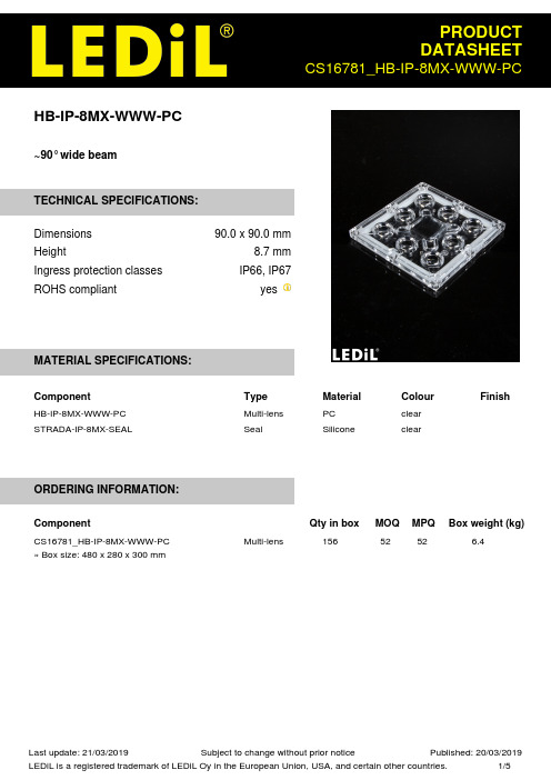
HB-IP-8MX-WWW-PC~90° wide beamTECHNICAL SPECIFICATIONS:Dimensions90.0 x 90.0 mmHeight8.7 mmIngress protection classes IP66, IP67ROHS compliant yesMATERIAL SPECIFICATIONS:Component Type Material Colour Finish HB-IP-8MX-WWW-PC Multi-lens PC clearSTRADA-IP-8MX-SEAL Seal Silicone clearORDERING INFORMATION:Component Qty in box MOQ MPQ Box weight (kg)Multi-lens 156 52 52 6.4CS16781_HB-IP-8MX-WWW-PC» Box size: 480 x 280 x 300 mmSee also our general installation guide: /installation_guidePHOTOMETRIC DATA (MEASURED):LED LUXEON 5050 Round LESFWHM / FWTM91.5° / 103.0°Efficiency94 %Peak intensity0.5 cd/lmLEDs/each optic1Light colour WhiteRequired components:PHOTOMETRIC DATA (SIMULATED):LED NFMW48xAFWHM / FWTM93.0° / 107.0°Efficiency90 %Peak intensity0.5 cd/lmLEDs/each optic1Light colour WhiteRequired components:GENERAL INFORMATION:NOTE: The typical beam angle will be changed by different color, chip size and chip position tolerance. The typical total beam angle is the full angle measured where the luminous intensity is half of the peak value.MATERIALS:As part of our continuous research and improvement processes, and to ensure the best possible quality and availability of our products, LEDiL reserves the right to change material grades without notice.PRODUCT DATA USER AGREEMENT AND DISCLAIMER:The measured data in the provided downloadable LEDiL Product Datasheets and Mechanical 2D-Drawings is rounded and provided as reference for planning. LEDiL Oy's optical specifications have been verified by conducting performance testing of the products in accordance with the company's quality system. The reported data are averaged results of multiple measurements with typical variation. LEDiL Oy reserves the right to without prior notification make changes and improvements to its products.LEDiL Oy assumes neither warranty, nor guarantee nor any other liability of any kind for the contents and correctness of the provided data. The provided data has been generated with highest diligence but the provided data may in reality not represent the complete possible variation range of all intrinsic parameters. Therefore, in certain cases a deviation from the provided data could occur.LEDiL Oy reserves the right to undertake technical changes of its products without further notification which could lead to changes in the provided data. LEDiL Oy assumes no liability of any kind for the possible deviation from any provided data or any other damage resulting from the usage of the provided data.The user agrees to this disclaimer and user agreement with the download or usage of the provided files.LEDiL OyJoensuunkatu 13FI-24240 SALOFinlandLEDiL Inc.228 West Page Street Suite DSycamore IL 60178USALedil Optics Technology (Shenzhen) Co., Ltd.# 405 , Block BCasic Motor Building Shenzhen 518057P.R.CHINALocal sales and technical support/where_to_buyShipping locations Salo, FinlandHong Kong, ChinaDistribution Partners /where_to_buyMouser ElectronicsAuthorized DistributorClick to View Pricing, Inventory, Delivery & Lifecycle Information:L edil:CS16781_HB-IP-8MX-WWW-PC。
封装规格书模板
Technical Specification Requirement2.5G 4PIN 1310nm DFB文件编号Document No. A000007319版本Version No.:A文件更改记录Document Change History目录1.PERFORMANCE SPECIFICATIONS(产品性能规格) (4)2.OUTLINE DIMENSION/IN MM(外框尺寸/单位:MM) (5)3.CRITERIAL COMPONENTS INFORMATION, LIKE CHIP ETC.(关键器件信息,如芯片等) (6)4.PROCESS REQUIREMENT(工艺需求) (8)5.RELIABILITY&RGA CRITERIA(可靠性&RGA 标准) (10)6.BOM清单 (10)1. Performance Specifications(产品性能规格)Table.2O‐Echaracteristics(Tc=25℃±2℃, Unless Other Wise Noted)Note:Pf = Light from the TOIf = Forward currentVf = Forward voltageVrP = Reversed bias for photo diode①:kink=(MAX(|MAXse-AVEse|,|MINse-AVEse|))/AVEse*100%Burn-in conditions:Burn-in current:100mA;TO case temperature:100℃;Duration:12HOURS Criterion condition:△Ith<1mA,△P<10%,△lm<10%2. Outline dimension/in mm(外框尺寸/单位:mm)3. Criterial components information, like CHIP etc.(关键器件信息,如芯片等) 3.1 LD CHIP information3.2 MPDCHIP informatio n4. Process requirement(工艺需求)4.1Die bonding diagram(贴片图)MPD 45°菱型贴装及LD贴装4.2Wire bonding diagram(绑线图)4.3CAP diagram(封帽图)4.4Process stage Request(工序需求)技术要求:固晶和共晶贴装4.4.1贴装顺序1)MPD载体,管座中心位置X=0±0.03mm、Y=-0.19±0.03mm,剪切力≥424gf2)MPD,管座中心位置X=0±0.03mm、Y=-0.03±0.03mm,MPD200剪切力≥132gf3)热沉,管座中心位置X=0.2±0.02mm、Z=1.30±0.02mm, θ角度≤±3°,剪切力≥297gf4)LD,X轴对中=0±0.01mm,Z轴=1.30±0.01mm,θ角度(发光条倾斜角度)≤±1°,剪切力≥107gfMPD载体胶量载体至少三面溢胶,并且至少一边可见胶长度大于该边的80%,高度不超过1/3。
电力型组合电阻柜(BOX)规格书

- 箱式保护外壳,内装选配德键 DR(平绕型线绕功率电阻器)系列或 DQ(波纹绕线功率电阻器)系列。 - 箱式(网格,屏蔽盖或固体底板)系列提供出色的保护和安全。 - 大型焊接框架的结构,提供强大的设计能力,易于功率电阻器在室内和 室外环境安装。 - 德键设计的 BOX 功率电阻箱系列提供无限组合方式,以满足客户的要求。
阻值范围(Ω)
5.5~20KΩ 5~40KΩ 4.5~40KΩ 4~80KΩ 3.5~120KΩ 3~160KΩ 2.5~200KΩ 2~240KΩ 1.5~280KΩ 1~320KΩ Version 2014
90 90 146 146 190 190 190 190
146 146
德键电子工业股份有限公司
TOKEN
BOX 电力型组合电阻柜 负载电阻箱
组合型电力负载电阻箱 (BQR) 300W - 4800W 尺寸
F
E
G
H
B C
D A
J
1
组合型电力负载电阻箱 (BQR) 尺寸图 功率
300W 600W 600W 1200W 1800W 2400W 3000W 3600W 4200W 4800W
尺寸(mm)
CASE A A B B C C D D D D A 345 345 450 450 450 450 560 560 560 560 B 90 90 152 152 300 300 250 250 250 250 C 76 76 100 100 100 100 195 195 195 195 D 325 325 428 428 428 428 535 535 535 535 E 45 45 30 30 74 74 27 27 27 27 F G 43 43 74 74 74 74 122 122 122 122 H I 8 8 10 10 10 10 10 10 10 10 J 268 268 355 355 355 355 420 420 420 420
ps08522ny系列规格书
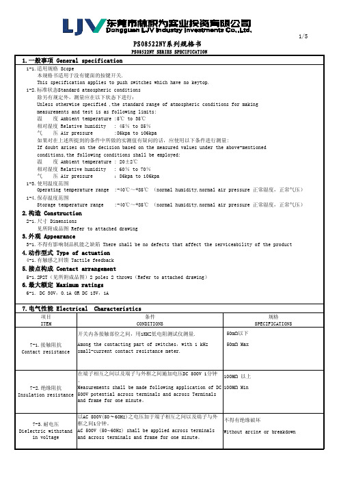
本规格书适用于没有键面的按键开关.This specification applies to push switches which have no keytop. 1-2.标准状态Standard atmospheric conditions 除另有规定外,测量应在以下状态下进行:Unless otherwise specified ,the standard range of atmospheric conditions for making measurements and test is as following limits:PS08522NY SERIES SPECIFICATION1.一般事项 General specification1-1.适用规格 Scope温 度 Ambient temperature : 20±2℃相对湿度 Relative humidity : 60% to 70% 气 压 Air pressure :86kpa to 106kpa 1-3.使用温度范围Operating temperature range :-40℃~+85℃ (normal humidity,normal air pressure 正常湿度,正常气压) 1-4.保存温度范围温 度 Ambient temperature :5℃ to 35℃ 相对湿度 Relative humidity : 45% to 85% 气 压 Air pressure :86kpa to 106kpa如果对在上述所提到的条件中所做的实测值有疑问的话,应使用以下条件进行测量:If doubt arises on the decision based on the measured values under the above-mentioned conditions,the following conditions shall be employed: Storage temperature range :-40℃~+85℃ (normal humidity,normal air pressure 正常湿度,正常气压)2.构造 Construction4.动作型式 Type of actuation4-1.有触感之回馈 Tactile feedback5.接点构成 Contact arrangement5-1.2P2T(见所附成品图)2 poles 2 throws(Refer to attached drawing)6.最大额定 Maximum ratings6-1. DC 30V,0.1A OR DC 13V,1A2-1.尺寸 Dimensions见所附成品图 Refer to attached drawing3.外观 Appearance3-1.不得有影响制品机能之缺陷 There shall be no defects that affect the serviceability of the product7-1.接触阻抗Contact resistance开关内各接触部位之间,用1KHZ低电阻测试仪测量.50m Ω以下Among the contacting part of switches,with 1 kHz small-current contact resistance meter.50m Ω Max7.电气性能 Electrical Characteristics项目条件规格ITEMCONDITIONSSPECIFICATIONS7-3.耐电压Dielectric withstand 以AC 500V(50∼60Hz)之电压加于端子相互之间以及端子与外框之间1分钟。
洛雷克Eco BLAcKBox系列产品说明书

LH010 Eco BLAcKBoX SeriesVIEW ON TABLET, SMARTPHONE, PC & MAC 24/7 RELIABLE RECORDINGAFFORDABLE PEACE OF MINDiPhone ®iPad ®REMoTE coNNEcTIVITY & coMPATIBILITY*SUPER-RESSERIES8cHANNELS 4 oR8cAMERAS 500 GB oR 1TB 600TVL RESoLUTIoN 90/66FT NIGHT VISIoNWATcH oVER YoUR WoRLDFROM ANYWHERE IN THE WORLDMoBILE SURVEILLANcEConnect and view your system on the go with your Tablet or Smartphone over a 3G/4G or WiFi network.†SIMPLE YET ADVANcEDRecord on a surveillance grade hard drive, designed for 24/7 operation providing weeks or even months of reliable recording.1SIMULTANEoUS MoNIToR VIEWING Connect to a TV, PC, or CCTV monitors with industry standard VGA & BNC inputs.EASY SYSTEM NAVIGATIoNIntuitive menu options with simple icons allow for fast and efficient DVR programming.•H.264 video compression. D1 capable1 •Real time recording @ (360x240)•Pentaplex operation - View, Record, Playback, Back Up & Remotely control the system simultaneously•24/7 100% Duty cycle hard drive pre-installed •PTZ camera (not included) supported via RS485 •Exclusive LOREX Easy Connect Internet Set-up Wizard 2 •Instant Mobile Viewing on compatible Smart phones & Tablets† •PC and Mac Compatible (Internet Explorer & Safari browsers)†•Free LOREX DDNS (Dynamic Domain Name Service) for advanced remote connectivity at all times•Instant email alerts with snap shot attachment•Accurate Time Stamps with NTP & Daylight Savings TimeDIGITAL VIDEo REcoRDER:LH010 Eco BLAcKBoX Series•Super Resolution with enhanced optics•BrightNight Viewing with enhanced lowlight image sensor•Night Vision up to 90/66ft (28/20m) away 3•Anti-glare feature ensures clear images under strong lighting conditions•Accurate colours with Lorex’s automatic light filtering technology• 3.6mm wide-angle lens captures a 78° Field of View (diagonal) 4•Vandal resistant design with cable pass through mounting bracket•Weatherproof housing for indoors & outdoor installation (IP66) 5•Versatile mounting options: ceiling, counter or wall mountableFEATURESTRUE coLoRSSee accurate colors with Lorex’s automatic light filtering technology.VANDAL RESISTANT DESIGNProtective cable pass-through bracket and metal housing.VIEW YOUR WORLD -IN SUPER RESOLUTION.CLEAR VIDEO DAY AND NIGHTVIEW WITH BRIGHT-NIGHTWEATHERPROOF HOUSINGA SUPER RESoLUTIoN PERSPEcTIVEView your world with improved detail, sharpness, and clarity day and night.Ambient Lighting Total Darkness90FT66FTANTI-GLAREcoLoR REPRoDUcTIoNTypicalCameraAccurate colors with InfraredFilter TechnologyTypicalCameraAnti-glareTechnologycoNNEcTIVITY Easy ConnectLorex Auto Port Forward WizardSupported Operating Systems 4/8/16 ch: Windows ™ XP , Vista, 74/8/16 ch: Mac OSX Snow Leopard 10.6 or above BrowsersInternet Explorer & Safari 6.0Email notification T ext with snapshotInstant Smart Phone Compatibility† Smart Phone & T ablet Compatibility: iPad ®, iPhone ®, BlackBerry (supported model numbers: 9000, 9700, 9800), Android (version 1.5 & above), Windows Mobile (6.0, 6.5), Symbian 3rd & 5th generation phones.DDNSFree Lorex DDNSSystem Configuration Full setup configuration over network PortsProgrammable by UserNetwork Protocol TCP/IP / DHCP / UDP / DDNS / PPPoE Network Interface 10/100-Base-TX, RJ-45 Network Speed Control 48Kb ~ 8MB/sec.GENERAL Power Consumption4/8/16 ch: Approx. 15 watts (HDD Pre-installed)Supply V oltage4/8/16 ch: 100V AC-240V AC, 12VDC , 2A, 50/60Hz Unit Dimensions 4/8/16 ch:11.81”/300mm x 8.66”/220mm x (W x D x H)1.97”/50mmUnit W eight (KGs) 4 & 8 ch: 1.32 kgs/2.9 Lbs16 ch: 1.51s kg/3.33 Lbs Operating temperature32° ~ 104° F / 0° ~ 40° C Humidity10 ~ 90% NCDVR:PRoDUcT SPEcIFIcATIoNSSYSTEM Operating System Linux (embedded)Pentaplex Simultaneous View, Record, Playback, Backup & Remote MonitoringNumber of Channels 4/8/16 ChannelInputs/outputs Video IN 4/8/16 x 1Vp-p, CVBS, 75ohms, BNC Video OUT 4/8 ch: 2 x BNC, 16 ch: 1 x BNC VGA OUT 4/8/16 ch: Y esAudio IN4/8 ch: 1 Line in(RCA), G.71116 ch: 2 Line in(RCA), G.711Audio OUT 4/8/16 ch: 1 line out(RCA), G.711USB Port 1 at the back for Mouse, 1 at the front for firmware upgrade &USB backupVideo Output Resolution 800x600, 1024x768, 1280x1024 PTZ control RS-485 Pelco D & P ProtocolDisplay Live Display 4 ch: 1,4 8 ch: 1, 4, 816 ch: 1, 4, 9, 16Live Display Speed 120 (4 ch)/ 240 (8 ch)/ 480 (16 ch) NTSC100 (4 ch)/ 200 (8 ch)/ 400 (16 ch) P ALOSD ON/OFFSystem Navigation USB Mouse, IR Remote ControllerMotion Area Setting Adjustable grid (10 x15) NTSC Adjustable grid (12 x15) P AL Sensitivity levels 8Firmware Upgrade Via USB device and Network User Authority By user groupTime Synchronization Auto time sync by NTP serverREcoRDINGVideo Compression H.264 Audio Compression G.711Recording Resolution 4/8 ch: NTSC: 360x240 (CIF), 720x240 (HD1), 720x480 (D1) 4/8 ch: P AL: 360x288 (CIF), 720x288 (HD1), 720x576 (D1)16 ch: NTSC: 360x240 (CIF), P AL: 360X288 (CIF)Recording Speed: 4 ch: 120/100 (NTSC/P AL) @ CIF , HD1, 60/50 (NTSC/P AL) @ D1 8 ch: 240/200 (NTSC/P AL) @ CIF , 120/100(NTSC/P AL) @ HDI, 60/50 (NTSC/P AL) @ D116 ch: 480/400 (NTSC/P AL) @ CIFRecording Resolution Setting Per camera for different resolutions (CIF/2CIF/D1). 16 ch: CIF only Recording Quality Control 3 levelsRecording ScheduleBy hour, by day , by recording mode, by motion, by channel Pre Recording Max. 10 Secs Post Recording Max. 5 Minutes Reliability W atch-Dog, Auto-recovery after power failure Covert Video Y esPLA YBAcKPlayback Channel 1~4 Adjustable(4 ch), 1~8 Adjustable (8 ch), 1~16Adjustable (16 ch)Playback Speed V ariable Max 16x Playback Players Backup Player Search By time & eventLog Search Up to 10,00,000 lines for motion detected, configurationchanges, connects/disconnects and video loss.Audio PlayY esSToRAGE & ARcHIVE Storage4/8/16 ch: Up to 1 HDD’s (SA T A) Maximum Capacity 4/8/16 ch: Up to 2TB Backup Media USB Flash Drive & HDDBackup File FormatH.264 file (A VI generator included)CAMERA (CVC7572PK4B):Image Sensor: 1/3” Color Image Sensor Video Format: NTSCEffective Pixels: H: 758 V: 488Resolution: 600 TV Lines Scan System: 2:1 Interlace Sync System: I nternal S/N Ratio: 46.8dB (AGC Off)Iris: AESAES Shutter Speed: 1/60 ~ 1/100,000 Sec.Min. Illumination: 0.1 Lux without IR LED0 Lux with IR LEDVideo Output: Composite 1.0Vpp @75 ohm Lens / Lens Type:3.6mm F1.2 / Fixed FOV (Diagonal): 78°T ermination: BNC Type IR LED Qty / Type: 24 pieces / 850nm Night Vision Range: 90ft (28m)/66ft (20m) Power Requirement: 12V DC ±10%Power Consumption:Max. 280mA (w/IR)Operating T emp. Range: 14° ~ 122°F / -10° ~ 50°C Operating Humidity Range: < 60% RH Environmental Rating: IP66W eight (including stand):0.6lbs / 0.3kgMoDEL coNFIGURATIoN PAcKAGE W x D x H - Inches & mm WEIGHT cUBE UPc code LH018511C4F8 CH DVR x 4 (600) TVL Cameras(CVC7572PK4B) x 500GB HDD Universal Retail Box435mm x 263mm x 313mm/17.3” x 10.38” x 12.32”6.5 kg/14.4 lbs0.036245m /1.28ft7-78597-18514-0LH08548 CH DVR x 4 (600) TVL Cameras(CVC7572PK4B) x 500GB HDD Retail English Giftbox 435mm x 263mm x 313mm/17.3” x 10.38” x 12.32”6.5 kg/14.4 lbs0.036245m /1.28ft7-78597-08540-2LH0181011C8F8 CH DVR x 8 (600) TVL Cameras(CVC7572PK4B) x 1TB HDDUniversal Retail Box 406mm x 431mm x 300mm/16” x 17” x 11.82”9.8 kg/21.65 lbs0.0526m /1.86ft7-78597-18118-0INCLUDES8 Ch DVR with pre-installed HDD, Remote Control, Power Adapter, Mouse, Ethernet Cable, CD, QSG, Instruction Manual, 4 or 8 x Cameras, 4 or 8 x Camera Stands, 4 or 8 x 60ft BNC/DC Extension Cables, 1 or 2 x 4 in 1 Camera Power Adaptors.© 2013 Lorex Technology Inc.As our product is subject to continuous improvement, Lorex Technology & subsidiaries reserve the right to modify product design, specifications &prices without notice and without incurring any obligation. E&OE.Lorex Technology Inc.250 Royal Crest CourtMarkham, Ontario, Canada L3R 3S12-02222013DVR Inputs & outputs901 Elkridge Landing Road, Suite 100Linthicum, Maryland 21090,USA.PRoDUcT INFoRMATIoN8 channel DVRDISCLAIMERS:1. Recording time may vary based on recording resolution & quality, lighting conditions and movement in the scene.2. Requires a high speed internet connection and a router (not included).3. IR Illumination range under ideal conditions. Actual range and clarity may vary depending on scene/object reflection and camera application. Measurements are calculated using ambient lighting and total darkness conditions. Picture automatically switches to B&W delivering better clarity in low light conditions.4. Not intended for submersion in water. Installation in a sheltered location recommended.† PC (Microsoft Windows™ 8/7/Vista/XP) compatible using Internet Explorer browser. Mac OSX Snow Leopard 10.6 or above using Safari browser.† Smartphone & Tablet Compatibility: iPad®, iPhone®, BlackBerry (supported model numbers: 9000, 9700, 9800), Android (version 1.5 & above), Windows Mobile (6.0, 6.5). Mobile phone data plan is required (not included). Router port forwarding required. For the latest compatibility list check as new models become available in the market.• BlackBox is used solely as a marketing term and does not imply that the product can survive fire or extreme conditions. Use product in accordance with the instructions provided.- Number of Channels/ Cameras/ Accessories/ HDD (hard disk drive) capacity may vary by model. Check your package label for specific content information.All trademarks belong to their respective owners. No claim is made to the exclusive right to use the trademarks listed, other than the trademarks owned by Lorex Technology Inc. We reserve the right to change models, configurations or specifications without notice or liability. Product may not be exactly as shown. Images are simulated.DVRDimensions:cVc7572PK4B cAMERA。
包装规格书Packaging Specification

Product Name :See list Model No : See list Author:N I L a d n i S Document Number : PKS120002 Document Revision : 1DCN NO:DCN201203059Change History:Approved by / DateRev.DetailsCreated By / DateIST TechBUBU MKT1 Preliminary Issue. 2012-03-16Description See the spreadsheet Supplier Distribution to:SupplierSupplierBU MarketingProduct ManagerProduct ManagerOCP PurchasingQC&SISC APOD ISTISC APOD ISTISC APOD IST zrtISC APOD IST zrtISC APOD IST zrtISC APOD IST zrtISC APOD IST zrtISC APOD ISTISC APOD ISTISC APOD IST zrtCreated byDescription See the spreadsheet Supplier zrtPacking Information:1. Pack product in blank bag and gift box with box label.Only for ACTPP2LED, the polybag should be sealed and apply polybag label.2. Pack the product into a outer carton with consistent qty on the spreadsheet, and applytwo shipper labels at the side of outer carton.3. Date code to be applied or visible at every level packaging.4. Barcodes must be printed as the spreadsheet & be scanned. The light marginindicator “>” isn’t required.5. Ensure the products &carton is securely taped and packed so that it will not bedamaged in shipment.6. The weight of a packed export carton / shipper must be under no circumstancesexceed 20kg. The shipper quantity must remain the same for all repeat orders.7. All products must be subject to the below tests:a) vibration test : IEC 60068-2-6b) drop test : Clipsal – WI0064 or IEC 68-2-31 but the dropping height follow thebelow.Note: If the product is delivered to China Distribution, please implement item 8, 9&10.8. Apply Warrany card.9. Apply Chinese description10. Apply the below information on the label of every level packaging:中国)有限公司总经销: 电气(中国地址: 北京市朝阳地址客户支持热线Packaging SpecificationPKS1200021e u s s I Product code See the spreadsheet Date created 2012-03-16Created by DescriptionSee the spreadsheetSupplierSPREADSHEET:n o t r a c r e t u ox o b t f i Gg a b y l o p Product code DescriptionUser manual qty dimension barcode qty dimension barcodeqtydimension barcode ACTPP2LED LED ModuleMS187421 70x111 4892552876242645x40x160 04892552876259 300335x240x22504892552876266ACTPP6ATGS24NSL Category 6A, ID-Tracer 24 Port Shielded Non-Shuttered Patch Panel, LoadedMS187411 n/a 1505x135x804892552876228 6525x260x30504892552876235ACTPP6S24NSL Category 6, ID-Tracer 24 Port Shielded Non-Shuttered Patch Panel, LoadedMS187411 n/a 1505x135x804892552876204 6525x260x30504892552876211ACTPP6U24NSLCategory 6, ID-Tracer 24 Port Unshielded Non-Shuttered Patch Panel, LoadedMS187411n/a1505x135x8048925528761816525x260x30504892552876198Created by Description See the spreadsheet SupplierPackaing condition:ACTPP6ATGS24NSL & ACTPP6S24NSLACTPP6U24NSLACTPP2LEDLabel:Polybag label Inner pack label Outer carton label Dimension 55X40mm 80X40mm 112x70mm)C553e n o t n aP(n e e r G+k c a l Br u o l oCMaterial White self adhesivePolybag labelCreated by Description See the spreadsheet SupplierInner pack labelOuter carton labelCreated by Description See the spreadsheet SupplierUser manual:Dimension: see the belowColour: BlackMaterial: 100gsm paperMS18742 (90mm x 90mm)MS18741 (Open size 286mm x 208mm)Created by Description See the spreadsheet SupplierWarranty Card:Dimension: 85mm x 85mmColour: BlackNote:Only apply a warranty card foreach product if it is delivered toChina Distribution Centre (DC).Please stamp batch code at theback of this card.Created by zrt Description See the spreadsheet SupplierGift box:Dimension: see the spreadsheet on the page4.Material: 250gsm + B9LED ModulePanelCreated by Description See the spreadsheet SupplierCarton:Dimension: see the spreadsheet on the page 4.Material: B三B, Brown Corrugate cardboard, 8-9mm Double Wall Printing on 4 sidesPackaging SpecificationPKS120002 1 e u s s I Product codeSee the spreadsheet Date created2012-03-16 Created by ZhangrentongDescription See the spreadsheet SupplierPallet: Dimension: 1200mm x 800mm x 150mm Loaded weight: minimum 500kg Loaded dimension: maximum. 1200mm x 800mm x 1300mm (Except HKIDC, the height can’t be over 1050mm) 4 way enty and comply with ISO Standard 3394。
鹰眼系列使用说明书

⑤将电源线插入 DC 口,并连接到汽车 12V DC 插座上。
⑥以上操作完成后,启动汽车电源,设备自动启动,当 LED 灯亮时,表示设备已经进入工 作状态。
12
3 安装后注意事项 ①在首次操作的前 30 秒内,请勿关闭设备电源,系统在初始化并寻找 GPS 信号。
如在此期间关闭电源,将导致问题。 ②注意:由于位置和环境的缘故,设备可能需要较长时间才能接收到 GPS 信号。 ③调节镜头角度。
请使用随机提供的电源线和指定的 12V DV 电源插头 (否则可能会导致损坏、着火或其他问题)
如果发现 G 撞击传感器的灵敏度比你设置的 还要敏感,请不要再使用,联系经销商
如果车辆因为事故造成电源线损坏请立即更换 (当使用中出现问题或闻到烟味,请不要使用,立即联系经销商)
6
以下指南使你能够正确使用 SD 卡
1
镜头 手动记录键 SD 存储卡槽
电源指示灯 灯亮表示电池能量足够工作
记录指示灯 灯亮表示正在记录 数据
2
DC 电源连接 视频输出(音频输出:可选) 数据输入
镜头外壳 固定支架
3
主机、SD 卡和读卡器
电源线
视频输出线
固定支架和黏帖片
用户手册 以上产品及附件如有丢失 和损坏,请及时联系当地 经销商或厂家。
23
安装两个镜头的情况
选择双镜头播放可同时出现前后记录画面。
可以把播放的录像内容存成照片格式。 将照片保存到任意文件夹中
24
项目
记录条件
记录
分辨率 1 通道
镜头
2 通道
G 传感器
A/V 格式
视频
音频
存储器
TV-OUT
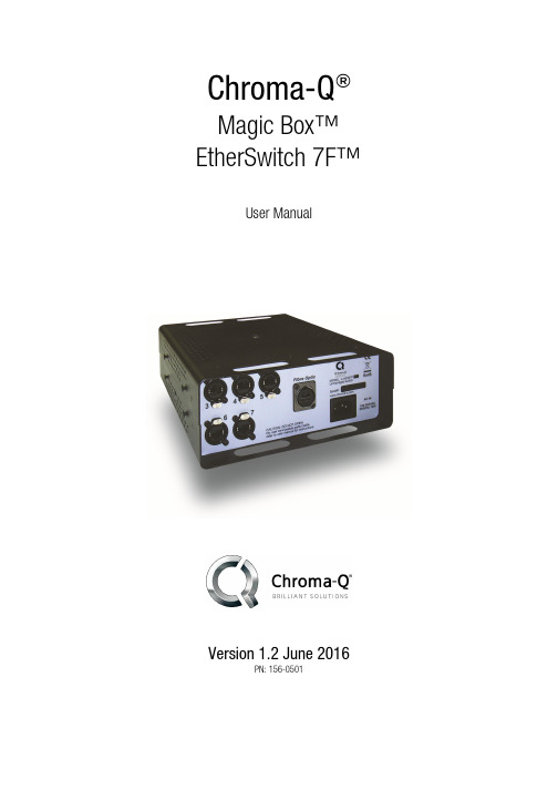
Chroma-Q Magic Box EtherSwitch 7F 用户手册说明书
Chroma-Q®Magic Box™ EtherSwitch 7F™User ManualVersion 1.2 June 2016PN: 156-0501Magic Box EtherSwitch 7 User Manual 1V1.1 September 2012Warranty StatementChroma-Q warrants to the original purchaser, with proof of purchase, that its delivered products shall be free from defects in material and workmanship under normal use for a period of 12 months from date of shipment.Chroma-Q will repair, or at its option, provide an equivalent item or replace, the defective product during the stated warranty period. This warranty applies only to the repair or replacement of the product and only when the product is properly handled, installed and maintained according to Chroma-Q instructions. This warranty excludes defects resulting from improper handling, storage, installation, acts of God, fire, vandalism or civil disturbances. Purchaser must notify Chroma-Q in writing within 14 days of noticing the defect. This warranty excludes field labour or service charges related to the repair or replacement of the product.The warranty contained herein shall not extend to any finished goods or spare parts from which any serial number has been removed or which have been damaged or rendered defective (a) as a result of normal wear and tear, willful or accidental damage, negligence, misuse or abuse; (b) due to water or moisture, lightning, windstorm, abnormal voltage, harmonic distortion, dust, dirt, corrosion or other external causes; (c) by operation outside the specifications contained in the user documentation; (d) by the use of spare parts not manufactured or sold by Chroma-Q or by the connection or integration of other equipment or software not approved by Chroma-Q unless the Customer provides acceptable proof to Chroma-Q that the defect or damage was not caused by the above; (e) by modification, repair or service by anyone other than Chroma-Q, who has not applied for and been approved by Chroma-Q to do such modification, repair or service unless the Customer provides acceptable proof to Chroma-Q that the defect or damage was not caused by the above; (f) due to procedures, deviating from procedures specified by Chroma-Q or (g) due to failure to store, install, test, commission, maintain, operate or use finished goods and spare parts in a safe and reasonable manner and in accordance with Chroma-Q’s instructions (h) by repair or replacement of engines without factory training.The warranty contained herein shall not apply to finished goods or spare parts which are sold “as is”, as “second-hand”, as used”, as “demo” or under similar qualifications or to Consumables (“Consumables” is defined as any part(s) of goods or part(s) for use with goods, which part(s) of goods or part(s) for use with goods are consumed during the operation of the goods and which part(s) of goods or part(s) for use with goods require replacement from time to time by a user such as, but not limited to, light bulbs).The warranty contained herein shall not apply, unless the total purchase price for the defective finished goods or spare parts has been paid by the due date for payment.The warranty contained herein applies only to the original purchaser and are not assignable or transferable to any subsequent purchaser or end-user.This warranty is subject to the shipment of the goods, within the warranty period, to theChromaQ warranty returns department, by the purchaser, at the purchasers expense. If no fault is found, ChromaQ will charge the purchaser for the subsequent return of the goods.Chroma-Q reserves the right to change the warranty period without prior notice and without incurring obligation and expressly disclaims all warranties not stated in this limited warranty. DisclaimerThe information contained herein is offered in good faith and is believed to be accurate. However, because conditions and methods of use of our products are beyond our control, this information should not be used in substitution for customer's tests to ensure that Chroma-Q products are safe, effective, and fully satisfactory for the intended end use. Suggestions of use shall not be taken as inducements to infringe any patent. Chroma-Q sole warranty is that the product will meet the sales specifications in effect at the time of shipment. Your exclusive remedy for breach of such warranty is limited to refund of purchase price or replacement of any product shown to be other than as warranted.Chroma-Q reserves the right to change or make alteration to devices and their functionality without notice due to our on going research and development.The Chroma-Q Magic Box EtherSwitch 7F system has been designed specifically for the lighting industry. Regular maintenance should be performed to ensure that the products perform well in the entertainment environment.If you experience any difficulties with any Chroma-Q products please contact your selling dealer. If your selling dealer is *********************************************.Ifthesellingdealerisunabletosatisfyyourservicingneeds,please contact the following, for full factory service:Outside North America: North America:Tel: +44 (0)1494 446000 Tel: 416-255-9494Fax: +44 (0)1494 461024 Fax: 416-255-3514****************************************For further information please visit the Chroma-Q website at .Chroma-Q is a trademark, for more information on this visit /trademarks.The rights and ownership of all trademarks are recognised.Magic Box EtherSwitch 7 User Manual 2 V1.1 September 2012Table of Contents1. Product Overview (4)2. Operation (4)2.1 Unpacking the units (4)2.2 Power (4)2.3 OpticalCon Fibre Optic and RJ45 Ethercon Ports (4)2.4 LED Indicators (5)2.5 Installation (5)3. Troubleshooting (5)4. Specification (6)4.1 Technical specification (6)4.2 Drawings (7)4. Maintenance (7)Magic Box EtherSwitch 7 User Manual 3 V1.1 September 2012Magic Box EtherSwitch 7 User Manual 4V1.1 September 20121. Product overviewThe EtherSwitch 7F is a heavy duty, high speed unmanaged network switch that supports simultaneous computer connections. Designed to satisfy the requirement of entertainment touring applications, the EtherSwitch 7F is equipped with one OpticalCon fibre optic connector supporting 1000Mbps, and seven shielded Ethercon (RJ45) ports supporting 10 / 100 / 1000 Mbps bandwidth in full-duplex mode. This stand-alone unit enables the concurrent use of various multimedia devices within a network without traffic restrictions.The unique Magic Box interlocking enclosure facilitates easy rack mounting when used in single units or pairs, and easy truss mounting via captive nut insert. Rack mounting brackets are available in single unit and dual unit versions, enabling you to customize your equipment rack or your installation by mixing and matching different Magic Box interface.2. Operation2.1 Unpacking the unitsThe EtherSwitch 7F package includes 1 EtherSwitch unit, a power cord and a Quick Start Guide. We recommend that you keep the original packaging in case items need to be returned.2.2 PowerPower for the EtherSwitch 7F is connected through a male IEC chassis connector with input rating of 100-240V AC, 50-60Hz. There is no power button and plugging into the power outlet will immediately power the unit on.2.3 OpticalCon Fibre Optic and RJ45 Ethercon PortsThe single OpticalCon fibre optic port at the rear panel supports 1000Mbps, and the 7 shielded RJ45 Gigabit Ethercon ports (2 x front panel; 5 x rear panel) support network speeds of 10Mbps / 100Mbps / 1000 Mbps which operate in half/full duplex transfer modes. The EtherSwitch 7F system utilises CAT5e cable to send and receive data in all IEEE 802.3 protocol, supports automatic MDI/MDIX crossover detection, and will automatically detect the settings of the external device immediately upon connection.Send and receive data (all IEEE 802.3 protocol) to and from an external source throughany of the seven shielded RJ45 Ethercon ports and one OpticalCon fibre optic port.OpticalCon Fibre Optic Port and RJ45 Ethercon Ports:Magic Box EtherSwitch 7 User Manual5V1.1 September 2012Front Panel: 2 Ethercon PortsRear Panel: 5 Ethercon Ports, 1 OpticalCon Fibre Optic Port2.4 LED Indicators1.The LED indicator for power at the front panel will light up (Green) when the EtherSwitch 7F is receiving power, otherwise, it is off.2.Cable diagnostic will start upon power up, which will determine if the Ethernet cables connected support 1000Mbps and a successful link is present. This process is indicated by the Speed LED corresponding to each of the 8 ports blinking (Green) sequentially.The initial port scan takes about 10 seconds. A detected cable fault or no link present will be indicated by the corresponding port’s Speed LED glowing (Amber) for 5 seconds after the initial port scan.A good cable connection will be indicated by the corresponding port’s Speed LED glowing (Green) for 5 seconds. The EtherSwitch 7F will then reset for normal operation.3.The Speed LED indicators (Top) at the front panel that corresponds to each port number will light up (Green) when a secure connection is present.The Activity LED (Bottom) will light up steady with a successful link and blink when reception or transmission of data is occurring at the port.4.The Speed LED indicator will light up green when the port is connected to a 1000Mbps Ethernet station, and amber when connected to a 100Mbps Ethernet device. The indicator will remain off when the port is connected to a 10Mbps Ethernet device.FActivity LED IndicatorsSpeed LED Indicators 34 52 17 6Magic Box EtherSwitch 7 User Manual 6V1.1 September 20122.5 InstallationUnique Magic Box interlocking enclosure facilitates easy rack mounting when used in pairs and easy truss mounting via captive nut insert. Rack mounting brackets are available in single unit and dual unit versions.Note: for truss mounting, we recommend the use of a ½"-13UNC x ¾" long bolt to avoid damage.3. TroubleshootingTroubleshooting is a process of elimination. First, rule out the other field factors (i.e. bad connections, faulty cables and power supplies). For technical advice and/or parts, please contact your selling dealer or the offices listed in this manual. Symptom Possible Cause Solution LED indicator for power is off. Power cord is not connected properly. There is no power at the source. Check power source, power cord andconnector.Speed LED lights amber upon cable diagnostic. Loose connection; damaged cable; damaged connector; no connection. Replace damaged cable. Check connector.Speed LED lights is off. No connection detected. Poor connection. Possible transmission fault at the source. Electronics fault in unit if it is connected to a 100/1000Mbps Ethernet device.Check connection/connectors. Check Ethernet device.Call selling dealer.4. Specification4.1 Technical specificationsProduct Code: CHES07FDimensions: 280mm x 220mm x 88mm 11" x 8.6" x 3.5" Weight: 3.5kg / 7.8lbsPower: 100-240V AC, 50-60Hz, 0.4A Power connector: IECEthernet Switch Type: Intelligent store & forward Ethernet Protocols: All IEEE 802.3RJ45/EtherCon Port: Shielded 10BaseT/ 100BaseTX/ 1000BaseT RJ45/EtherCon: Auto-negotiation RJ45/EtherCon MDI/MDIX: Auto-crossover RJ45/EtherCon TD and RD polarity: Auto-polarity OpticalCon Port:1000 Mbps MAC Addresses Supported: 8192 VLAN Supported: 4096 Jumbo Frame Support: up to 9.6K Buffer Memory: 144 KbytesMemory Bandwidth:16 Gbps for full wire speed on all portsForwarding Rate: 10 Mbps : 14,880pps100 Mbps : 148,81pps1000 Mbps : 1488,1ppsPort Connection: Link and Activity LED indicatorsPower: Power LEDMax Fiber Optic cable run: 550m / 1800ftColour: BlackApprovals : CISPR 22:2006/EN55022:2006, CISPR 24:1997/EN55024:1998, ICES-003:2004, FCC Part 15 Subpart B:2007, CSA C22. No. 166-M1983:R2008CAN/CSA-C22.2 No. 60950-1-07, UL 60950-1:2007Magic Box EtherSwitch 7 User Manual 7 V1.1 September 2012Magic Box EtherSwitch 7 User Manual 8V1.1 September 20124.2 Drawings5. MaintenanceWith care, the Chroma-Q Magic Box EtherSwitch 7F will require little maintenance. However, as the unit is likely to be used in a stage environment we recommend periodical internal inspection and cleaning of any resulting dust and cracked oil residue.Do not spray liquids on the front or rear panel. If the front enclosure requires cleaning, wipe with a mild detergent on a damp cloth.。
