广数G代码
广数铣床G代码指令

广数铣床G代码指令广数铣床G代码指令G00——定位(快速移动)G01——直线插补(切削进给)G02——顺时针圆弧/螺旋线插补G03——逆时针圆弧/螺旋线插补G04——暂停/准停G07.1——圆柱插补G10——可编程数据输入G15——取消极坐标指令方式G16——极坐标指令方式开始G17——XY平面选择G18——ZX平面选择G19——YZ平面选择G20——英制输入G21——公制输入G28——返回参考点G29——从参考点返回G30——返回第2,3,4参考点G31——跳跃机能G40——取消刀具半径补偿G41——刀具半径左补偿G42——刀具半径右补偿G43——刀具长度正向补偿G44——刀具长度负向补偿G49——取消刀具长度补偿G50——取消比例缩放G51——比例缩放开始G50.1——取消可编程镜像G51.1——设置可编程镜像G52——局部坐标系设定G53——选择机床坐标系G54.1——附加工件坐标系G54——工件坐标系1G55——工件坐标系2G56——工件坐标系3G57——工件坐标系4G58——工件坐标系5G59——工件坐标系6G65——宏指令G66——宏程序模态调用G67——宏程序模态调用取消G68——坐标旋转开始G69——坐标旋转取消G73——高速深孔加工循环G74——左旋攻丝循环G76——精镗循环G80——取消固定循环G81——钻孔循环(点钻循环)G82——钻孔循环(镗阶段孔循环)G83——深孔钻循环G84——攻丝循环G85——镗孔循环G86——镗削循环G87——背镗循环G88——镗孔循环G89——镗孔循环G90——绝对值编程G91——增量值编程G92——坐标系设定G94——每分钟进给G95——每转进给G98——固定循环中返回初始平面G99——固定循环中返回R平面G110——逆时针圆凹槽内粗铣G111——顺时针圆凹槽内粗铣G112——逆时针全圆内精铣G113——顺时针全圆内精铣G114——逆时针外圆精铣G115——顺时针外圆精铣G116——逆时针外圆粗铣G117——顺时针外圆粗铣G132——逆时针外矩形粗铣G133——顺时针外矩形粗铣G134——逆时针外矩形凹槽粗铣G135——顺时针矩形凹槽粗铣G136——逆时针矩形凹槽内精铣G137——顺时针矩形凹槽内精铣G138——逆时针矩形外精铣G139——顺时针矩形外精铣G140——顺时针矩形连续钻孔G141——逆时针矩形连续钻孔G142——顺时针弧形连续钻孔G143——逆时针弧形连续钻孔广数铣床G代码功能详解G00——定位(快速移动)格式:G00 X__Y__Z__功能:X轴、Y轴、Z轴同时从起点以各自的快速移动速度移动到终点。
数控编程G代码

目录
• G代码基础 • G代码指令详解 • G代码编程实例 • G代码优化与注意事项 • G代码的发展趋势与未来展望
01
G代码基础
G代码的定义与特点
01
G代码(也称为G-code)是一种数控编程语言,用于控制 数控机床(CNC机床)的运动和加工过程。
02
G代码具有高度的灵活性和通用性,可以在不同的数控机床上 使用,并且可以通过修改参数和程序来控制机床的各种运动和
G代码的编程原理要求程序员对机械加工、刀具、材料等有一定的了解,以确保加工过 程的准确性和安全性。
G代码的编程步骤
确定加工工艺
根据工件图纸和加工要求,确定加工 工艺和参数,如刀具、切削参数、加 工顺序等。
监控与调整
在加工过程中,需要实时监控机床的 运动状态和加工结果,根据需要进行 调整和优化。
01
详细描述
使用G代码编程,可以方便地控制数控机床 的刀具路径,实现简单零件的加工。例如, 使用G00指令快速定位到起始点,使用G01 指令进行直线插补,使用G02和G03指令进 行圆弧插补等。
复杂零件的G代码编程
总结词
适用于复杂形状的零件,如曲面、异形件等。
详细描述
对于复杂零件,需要使用更高级的G代码编程技巧。例如,使用G28指令自动返回参考 点,使用G21和G20指令设置单位为毫米或英寸,使用G28指令自动返回参考点等。此
G04-定时延时
总结词
该指令使刀具在设定的时间内暂停移动 ,实现延时效果。
VS
详细描述
G04指令用于定时延时,使刀具在设定的 时间范围内暂停移动,常用于等待冷却液 冷却、工件加工完成等操作,以提高加工 质量和效率。
03
广州数控指令代码大全

广州数控指令代码大全广州数控指令代码大全2011-01-31 02:13GSK980TA/D编程教材《一》编程的基本概念《二》常用G代码介绍《三》单一固定循环《四》复合型固定循环《五》用户宏程序《六》螺纹加工《七》T代码及刀补《八》F代码及G98、G99《九》S代码及G96、G97(注意:本教材仅供学习参考,实际操作编程时应以广数GSK980T车床数控系统使用手册为准)2007年9月《一》编程的基本概念:一个完整的车床加工程序一般用于在一次装夹中按工艺要求完成对工件的加工,数控程序包括程序号、程序段。
(一)程序号:相当于程序名称,系统通过程序号可从存储器中多个程序中识别所要处理的程序,程序号由字母O及4位数字组成。
(二)程序段:相当于一句程序语句,由若干个字段组成,最后是一个分号(;)录入时在键入EOB键后自动加上。
整个程序由若干个程序段构成,一个程序段用来完成刀具的一个或一组动作,或实现机床的一些功能。
(三)字段(或称为字):由称为“地址”的单个英语字母加若干位数字组成。
根据其功能可分成以下几种类型的字段:▲程序段号:由字母N及数字组成,位于程序段最前面,主要作用是使程序便于阅读,可以省略,但某些特殊程序段(如表示跳转指令的目标程序段)必须标明程序段号。
为了便于修改程序时插入新程序段,各句程序段号一般可间隔一些数字(如N0010、N0020、N0030)。
▲准备功能:即G代码,由字母G及二位数字组成,大多数G 代码用以指示刀具的运动。
(如G00、G01、G02)▲表示尺寸(坐标值)的字段:一般用在G代码字段的后面,为表示运动的G代码提供坐标数据,由一个字母与坐标值(整数或小数)组成。
字母包括:表示绝对坐标:X、Y、Z表示相对坐标:U、V、W表示园心坐标:I、 J、 K(车床实际使用的坐标只有X、Z,所以Y、V、J都用不着)▼表示进给量的字段:用字母F加进给量值组成,一般用在插补指令的程序段中,规定了插补运动的速度。
G代码一览表

G代码一览表G 代码是数控编程中用于控制机床运动和功能的指令代码。
在数控机床的加工过程中,正确理解和运用 G 代码至关重要。
下面为您详细列出常见的 G 代码及其功能。
G00:快速定位这个代码用于将刀具快速移动到指定的位置,其移动速度是机床设定的最快速度,通常不进行切削加工。
G01:直线插补它能让刀具沿着直线轨迹进行切削加工,需要指定移动的终点坐标和进给速度。
G02:顺时针圆弧插补用于指定顺时针方向的圆弧加工路径,需要给定圆弧的终点坐标、圆心坐标或者半径,以及切削进给速度。
G03:逆时针圆弧插补与 G02 相反,用于逆时针方向的圆弧加工。
G04:暂停在程序执行过程中,使用 G04 可以让刀具在指定的时间内暂停动作,常用于给加工留出足够的时间,如让切削液充分冷却工件等。
G17、G18、G19:平面选择G17 选择 XY 平面,G18 选择 XZ 平面,G19 选择 YZ 平面。
这决定了后续圆弧插补等指令所参考的平面。
G20、G21:单位设定G20 设定单位为英寸,G21 设定单位为毫米。
G28:返回参考点使刀具自动返回机床设定的参考点。
G30:返回第二、第三和第四参考点除了常见的第一参考点,机床还可以设定多个参考点,通过 G30 指令可以返回指定的参考点。
G40、G41、G42:刀具半径补偿G40 取消刀具半径补偿,G41 为左补偿,G42 为右补偿。
在进行轮廓加工时,根据刀具与工件的相对位置选择合适的补偿方式,以确保加工精度。
G43、G44、G49:刀具长度补偿G43 为正补偿,G44 为负补偿,G49 取消刀具长度补偿。
用于补偿刀具长度的差异,确保加工深度的准确性。
G50:坐标系设定可以设定工件坐标系的坐标原点和坐标轴的最大值、最小值。
G54 G59:工件坐标系选择预先设定多个工件坐标系,通过这些代码可以快速切换使用。
G70:精车循环用于进行精加工。
G71:外圆粗车循环适用于外圆的粗加工。
G72:端面粗车循环针对端面进行粗加工。
广数铣床代码

广数铣床代码G代码功能 G代功能码G00 定位 G57 选择工件坐标系4 G01 直线插补 G58 选择工件坐标系5 G02 圆弧插补/螺旋线G59 选择工件坐标系6插补CWG03 圆弧插补/螺旋线G60 单向定位插补CCWG04 暂停 G61 准确停止方式 G07.1 圆柱插补 G62 自动拐角倍率 G09 准确停止 G63 攻丝方式 G10 可编程数据输入 G64 切削方式 G11 可编程数据输入G65 宏程序单一调用方式取消G15 极坐标指令取消 G66 宏程序模态调用 G16 极坐标指令 G67 宏程序模态调用取消 G17 选择XpYp平面 G68 坐标系旋转/三维坐标系转换 G18 选择ZpXp平面 G69 坐标系旋转/三维坐标系转换取消 G19 选择YpZp平面 G73 高速深孔钻孔循环 G20 英寸输入 G74 左旋攻丝循环 G21 毫米输入 G76 精镗循环 G22 存储行程检测功G80 固定循环取消能有效G23 存储行程检测功G81 钻孔循环、锪镗循环能无效G27 返回参考点检测 G82 钻孔循环或反镗循环 G28 返回参考点 G83 深孔钻孔循环 G29 从参考点返回 G84 右旋攻丝循环 G30 返回第2,3,4G85 镗孔循环参考点G31 跳转功能 G86 镗孔循环 G33 螺纹切削 G87 反镗循环 G34 圆周孔循环G88 镗孔循环 G35 角度直线孔循环 G89 镗孔循环 G36 圆弧连续孔循环 G90 绝对值编程 G37 棋盘孔循环 G91 增量值编程 G40 刀具半径补偿取G92 设定工件坐标系消G41 左侧刀具半径补G92.1 工件坐标系预置偿G42 右侧刀具半径补G94 每分进给偿G43 正向刀具长度补G95 每转进给偿G44 负向刀具长度补G96 恒表面速度控制偿G45 刀具偏置值增加 G97 恒表面速度控制取消 G46 刀具偏置值减小 G98 固定循环返回到初始点 G47 2倍刀具偏置值 G99 固定循环返回到R点 G48 1/2倍刀具偏置G110 逆时针圆内凹槽初铣循值环 G49 刀具长度补偿取G111 顺时针圆内凹槽初铣循消环 G50 比例缩放取消 G112 逆时针全圆内精铣循环 G51 比例缩放有效G113 顺时针全圆内精铣循环 G50.1 可编程镜像取消 G114 逆时针全圆外精铣循环G51.1 可编程镜像有效 G115 顺时针全圆外精铣循环 G52 局部坐标系设定 G120 面铣循环 G53 选择机床坐标系 G134 逆时针矩形凹槽初铣循环 G54 选择工件坐标系G135 顺时针矩形凹槽初铣循1 环 G54.1 选择附加工件坐G136 逆时针矩形凹槽精铣循标系环 G55 选择工件坐标系G137 顺时针矩形凹槽精铣循2 环 G56 选择工件坐标系G138 逆时针矩形外精铣循环3G57 选择工件坐标系G139 顺时针矩形外精铣循环4G58 选择工件坐标系G140 顺时针矩形连续钻孔循5 环 G59 选择工件坐标系G141 逆时针矩形连续钻孔循6 环。
广州数控指令代码大全
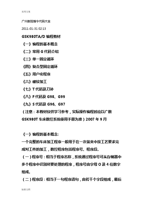
广州数控指令代码大全2011-01-31 02:13GSK980TA/D编程教材《一》编程的基本概念《二》常用G代码介绍《三》单一固定循环《四》复合型固定循环《五》用户宏程序《六》螺纹加工《七》T代码及刀补《八》F代码及G98、G99《九》S代码及G96、G97(注意:本教材仅供学习参考,实际操作编程时应以广数GSK980T车床数控系统使用手册为准)2007年9月《一》编程的基本概念:一个完整的车床加工程序一般用于在一次装夹中按工艺要求完成对工件的加工,数控程序包括程序号、程序段。
(一)程序号:相当于程序名称,系统通过程序号可从存储器中多个程序中识别所要处理的程序,程序号由字母O及4位数字组成。
(二)程序段:相当于一句程序语句,由若干个字段组成,最后是一个分号(;)录入时在键入EOB键后自动加上。
整个程序由若干个程序段构成,一个程序段用来完成刀具的一个或一组动作,或实现机床的一些功能。
(三)字段(或称为字):由称为“地址”的单个英语字母加若干位数字组成。
根据其功能可分成以下几种类型的字段:▲程序段号:由字母N及数字组成,位于程序段最前面,主要作用是使程序便于阅读,可以省略,但某些特殊程序段(如表示跳转指令的目标程序段)必须标明程序段号。
为了便于修改程序时插入新程序段,各句程序段号一般可间隔一些数字(如N0010、N0020、N0030)。
▲准备功能:即G代码,由字母G及二位数字组成,大多数G 代码用以指示刀具的运动。
(如G00、G01、G02)▲表示尺寸(坐标值)的字段:一般用在G代码字段的后面,为表示运动的G代码提供坐标数据,由一个字母与坐标值(整数或小数)组成。
字母包括:表示绝对坐标:X、Y、Z表示相对坐标:U、V、W表示园心坐标:I、J、K(车床实际使用的坐标只有X、Z,所以Y、V、J都用不着)▼表示进给量的字段:用字母F加进给量值组成,一般用在插补指令的程序段中,规定了插补运动的速度。
▼S代码:表示主轴速度的字段。
广州数控G代码
G80 固定循环取消
G81 固
定循环(钻孔/铅孔)
G82 固定循环(钻孔/计数式搪孔)
G83 固定循环(深钻孔)
G84 固定循环(攻牙)
G85 固定循环(搪孔)
G86 固定循环(搪孔)
M88 —— M97 没有
M98 调用子程序
M99 子程序结束 回答人的补充 2010-03-19 19:36 fanuc数控指令
G00快速定位,G01直线插补,G02顺时针插补,G03逆时针插补,G04暂停,G40取消刀补,G41左补,G42右补,G54-G59工件坐标系{车床、加工中心都一样}。G70精加工复合循环,G71外圆粗加工循环,G72端面粗加工循环,G73固定形状粗加工循环,G74端面钻孔循环,G75外圆切槽循环,G76外圆螺纹循环,M指令同加工中心差不多 。
G08 * 加速 G58
直线偏移XZ
G09 * 减速 G59 直线偏移YZ
G10-G16 * 不指定 G60 准确定位(精)
G17 XY平面选择 G61 准确定位(中)
G18 ZX平面选择 G62 准确定位(粗)
M71 刀套向下
M72 换刀臂60°
M73 主轴松刀
M74 换刀臂180°
M75 主轴夹刀
M76 换刀臂0°
M77 刀臂向上
M78 —— M80 没有
M81 工作台交换确认
M82 工作台上
M83 工作台下
M84 工作台伸出
M85 工作台缩回
M86 工作台门开
M87 工作台门关
G46 * 刀具偏置+/- G95 主轴每转进给
数控机床编程G代码

刀具位置偏置加2倍
00
刀具位置偏置减2倍
08
刀具长度补偿取消
比例缩放取消
11
比例缩放有效
14
选择工件坐标系3
可编程镜像取消 22
可编程镜像有效
局部坐标系设定 00
选择机床坐标系
选择工件坐标系1
14
选择附加工件坐标系
选择工件坐标系2
G57
选择工件坐标系4
G58
14
选择工件坐标系5
G59
选择工件坐标系6
G82
钻孔循环或反镗
G82
09
钻孔循环或反镗
G83
深孔钻循环
G84
攻丝循环
G85
镗孔循环
G86
镗孔循环
G87
背镗循环
G88
镗孔循环
G89 G90 G91 G92
G92.1 G94 G95 G96 G97 G98 G99
09
镗孔循环
绝对值编程
03
增量值编程
设坐标系最大主轴速度控制
00 工件坐标系预置
G60
00/01
单方向定位
G61
准确停止方式
G62
自动拐角方式
G63
15
攻丝方式
G64
切削方式
G65
00
宏程序调用
G66
宏程序模态调用
G67
12
宏程序模态调用取消
G68
坐标旋转有效
G69
16
坐G74
左旋攻丝循环
G76
精镗循环
G80
固循环取消/外操作功能取消
G81
钻、锪镗或外操作功能
G15
极坐标指令消除
广州数控车床指令代码大全

广州数控车床指令代码大全Hessen was revised in January 20211、 GSK980Ta功能列表代码组别意义格式G00快速定位G00X(U)_ Z (W) _G01直线插补G01X(U)_ Z (W) _ F_G02圆弧插补(顺时针方向CW)G02 X_Z_R_F或G02 X_Z_ I_K_FG03圆弧插补(逆时针方向CCW)G03 X_Z_R_F或G03 X_Z_ I_K_FG04暂停G04 P_;(单位:0.001秒)G04 X_;(单位:秒)G04 U_;(单位:秒)G28自动返回机械原点G28 X(U)_ Z (W) _G32切螺纹G32X(U)_ Z(W) _ F _(公制螺纹)G32X(U)_ Z(W) _ I _(英制螺纹)G50坐标系设定G50 X(x) Z(z)G70精加工循环G70 P(ns) Q(nf)G71外圆粗车循环G71U(△D)R(E)F(F)G71 P(NS)Q(NF)U(△U)W(△W) S(S)T(T)G72端面粗车循环G72W(△D)R(E)F(F)G72 P(NS)Q(NF)U(△U)W(△W)S(S)T(T)G73封闭切削循环G73 U(△I)W(△K) R(D)F(F)G73 P(NS)Q(NF)U(△U)W(△W)S(S)T(T)G74端面深孔加工循环G74 R(e)G74 X(U) Z(W) P(△i)Q(△k)R(△d)F(f)G75外圆、内圆切槽循环G75 R(e)G75 X(U) Z(W) P(△i)Q(△k)R(△d)F(f)G76复合型螺纹切削循环G76 P(m)(r)(a)Q(△dmin)R(d) G76 X(U) Z(W) R(i) P(k)Q(△d) F(L)G91外圆、内圆车削循环G90X(U)_Z(W)_R_F_G92螺纹切削循环G92X(U)_ Z(W) _ F _(公制螺纹)G92X(U)_ Z(W) _ I _(英制螺纹)G94端面车削循环G94 X(U)_Z(W)_F_G98每分进给G98G99每转进给G992、GSK980T M功能列表代码意义格式:M00程序暂停,按“循环起动”程序继续执行M01程序计划停止M02程序结束M03主轴正转M04主轴反转M05主轴停止M08冷却液开M09冷却液关M30程序结束并返回程序起点M98子程序调用M98 PxxxxnnnnM99子程序结束M99螺纹切削循环 G92指令格式:G92 X(U)_ Z(W)_ F_ J_ K_ L ;(公制直螺纹切削循环)G92 X(U)_ Z(W)_ I_ J_ K_ L ;(英制直螺纹切削循环)G92 X(U)_ Z(W)_ R_ F_ J_ K_ L ;(公制锥螺纹切削循环)G92 X(U)_ Z(W)_ R_ I_ J_ K_ L ;(英制锥螺纹切削循环)指令功能:从切削起点开始,进行径向(X 轴)进刀、轴向(Z 轴或 X、Z 轴同时)切削,实现等螺距的直螺纹、锥螺纹切削循环。
广数G 代码命令

G 代码命令代码组及其含义“模态代码”和“一般”代码“形式代码”的功能在它被执行后会继续维持,而“一般代码”仅仅在收到该命令时起作用。
定义移动的代码通常是“模态代码”,像直线、圆弧和循环代码。
反之,像原点返回代码就叫“一般代码”。
每一个代码都归属其各自的代码组。
在“模态代码”里,当前的代码会被加载的同组代码替换。
G代码组别解释G00 01 定位(快速移动)G01 直线切削G02 顺时针切圆弧G03 逆时针切圆弧)G04 暂停)G09 停于精确的位置G20 英制输入G21 公制输入G22 04 内部行程限位有效G23 内部行程限位无效G27 00 检查参考点返回G28 参考点返回G29 从参考点返回G30 回到第二参考点G32 01 切螺纹G40 07 取消刀尖半径偏置G41 刀尖半径偏置(左侧)G42 刀尖半径偏置(右侧)G50 00 修改工件坐标;设置主轴最大的RPMG52 设置局部坐标系G53 选择机床坐标系G70 00 精加工循环G71 内外径粗切循环G72 端面粗切循环G73 复合切削循环G74 Z 向步进钻削G75 X 向切槽G76 切螺纹循环G80 10 取消固定循环G83 钻孔循环G84 攻丝循环G85 正面镗孔循环G87 侧面钻孔循环G88 侧面攻丝循环G89 侧面镗孔循环G90 01 (内外直径)切削循环G92 切螺纹循环G94 端面切削循环G96 恒线速度控制G97 恒线速度控制取消G98 每分钟进给率G99 每转进给率还有M代码常用的是有MOO程序暂停MO1程序选者暂停MO2程序结束MO3主轴正转M08冷却开M09冷却关MO5主轴停MO4主轴反转M30程序结束并反回程序头M98调用子程序M99子程序结束。
数控编程广数GSKT

复习提问辅助指令都有哪些?新课引入辅助指令主要是用来对机床功能开关的,它们不能够移动刀架,刀具的移动才能够进行切屑运动,切屑指令是指G指令,今天我们就开始学习基本的G指令。
快速定位G00代码格式:G00 X(U) __Z(W) __;代码功能:X轴、Z轴同时从起点以各自的快速移动速度移动到终点,如图3-1所示。
两轴是以各自独立的速度移动,短轴先到达终点,长轴独立移动剩下的距离,其合成轨迹不一定是直线。
代码说明: G00为01组G代码的初值;X(U)、Z(W)可省略一个或全部,当省略一个时,表示该轴的起点和终点坐标值一致;同时省略表示终点和始点是同一位置,X与U、Z与W在同一程序段时X、Z有效,U、W无效。
运动轨迹图:X、Z 轴各自快速移动速度分别由系统数据参数、设定,实际的移动速度可通过机床面板的快速倍率键进行修调。
示例:刀具从A 点快速移动到B 点。
图3-2直线插补G01代码格式:G01 X(U)_ Z(W)_ F_;代码功能:运动轨迹为从起点到终点的一条直线。
轨迹如图3-3 所示。
代码说明: G01为模态G代码;X(U)、Z(W)可省略一个或全部,当省略一个时,表示该轴的起点和终点坐标值一致;同时省略表示终点和始点是同一位置。
F 代码值为X 轴方向和Z 轴方向的瞬时速度的向量合成速度,实际的切削进给速度为进给倍率与F 代码值的乘积;F 代码值执行后,此代码值一直保持,直至新的F 代码值被执行。
后述其它G 代码使用的F 代码字功能相同时,不再详述。
取值范围见表1-10。
注:G98 状态下,F 的最大值不超过数据参数NO027(切削进给上限速度)设置值。
运动轨迹图:示例:从直径Φ40 切削到Φ60 的程序代码,图3-4小结编程练习复习提问G01的格式是什么?新课引入G00用于快速定位,不能用于切屑,G01用于直线切屑,如锥度、断面、外圆加工,今天我们学习圆弧加工指令:G02、G03。
圆弧插补G02、G03代码格式: G02 /G03 X(U)__ Z(W)__ R__F__G02 /G03 X(U)__ Z(W)__ I__ K__F__代码功能:G02代码运动轨迹为从起点到终点的顺时针(后刀座坐标系) 圆弧从起点到终点的逆时针(前刀座坐标系)圆弧,轨迹如图3-5所示。
GSK广州数控车G代码一览表

G00 快速定位
G50 设置工件坐标系
G01 直线插补
G65 宏指令
G02 顺时针圆弧插补
G70 精加工循环
G03 逆时针圆弧插补
G71 轴向粗车循环
G04 暂停、准停
G72 径向粗车循环
G10 数据输输入方式
G74 轴向切槽循环
G20 英制单位选择
G75 径向切槽循环
G21 公制单位选择
G76 多重螺纹切削循环
G28 自动返回机械零点
G90 轴向切削循环
G30 回机床第 2 、 3 、 4 参考点
G92 螺纹切削循环
G32 等螺距螺纹切削
G94 径向切削循环
G33 Z 轴攻丝循环
G96 恒线速控制
G34 变螺距螺纹切削
G97 取消恒线速控制
G40 取消刀尖半径补偿
G98 每分进给
G41 刀尖半径左补偿
G99 每转进给
G42 刀尖半径右补偿
数控编程G代码大全
G代码功能G代码是数控程序中的指令。
一般都称为G指令。
代码名称-功能简述G00------快速定位G01------直线插补G02------顺时针方向圆弧插补G03------逆时针方向圆弧插补G04------定时暂停G05------通过中间点圆弧插补G06------抛物线插补G07------Z 样条曲线插补G08------进给加速G09------进给减速G10------数据设置G16------极坐标编程G17------加工XY平面G18------加工XZ平面G19------加工YZ平面G20------英制尺寸(法兰克系统)G21-----公制尺寸(法兰克系统)G22------半径尺寸编程方式G220-----系统操作界面上使用G23------直径尺寸编程方式G230-----系统操作界面上使用G24------子程序结束G25------跳转加工G26------循环加工G30------倍率注销G31------倍率定义G32------等螺距螺纹切削,英制G33------等螺距螺纹切削,公制G34------增螺距螺纹切削G35------减螺距螺纹切削G40------刀具补偿/刀具偏置注销G41------刀具补偿——左G42------刀具补偿——右G43------刀具偏置——正G44------刀具偏置——负G45------刀具偏置+/+G46------刀具偏置+/-G47------刀具偏置-/-G48------刀具偏置-/+G49------刀具偏置0/+G50------刀具偏置0/-G51------刀具偏置+/0G52------刀具偏置-/0G53------直线偏移,注销G54------直线偏移xG55------直线偏移yG56------直线偏移zG57------直线偏移xyG58------直线偏移xzG59------直线偏移yzG60------准确路径方式(精)G61------准确路径方式(中)G62------准确路径方式(粗)G63------攻螺纹G68------刀具偏置,内角G69------刀具偏置,外角G70------英制尺寸寸(这个是西门子的,法兰克的是G21)G71------公制尺寸毫米G74------回参考点(机床零点)G75------返回编程坐标零点G76------车螺纹复合循环G80------固定循环注销G81------外圆固定循环G331-----螺纹固定循环G90------绝对尺寸G91------相对尺寸G92------预制坐标G93------时间倒数,进给率G94------进给率,每分钟进给G95------进给率,每转进给G96------恒线速度控制G97------取消恒线速度控制功能详解快速定位格式:G00 X(U)__Z(W)__说明:(1)该指令使刀具按照点位控制方式快速移动到指定位置。
广数G代码

4.1.4数控车床的分类数控车床品种繁多,按数控系统功能和机械构成可分为简易数控车床(经济型数控车床)、多功能数控车床和数控车削中心。
(1)简易数控车床(经济型数控车床)是低档次数控车床,一般是用单板机或单片机进行控制,机械部分是在普通车床的基础上改进设计的。
(2)多功能数控车床也称全功能型数控车床,由专门的数控系统控制,具备数控车床的各种结构特点。
(3)数控车削中心在数控车床的基础上增加其他的附加坐标轴。
4.1.5数控车床(CJK6153)的主要技术规格。
床身最大工具回转直径:ф530mm。
滑板最大工件回转直径:ф280mm,机床顶尖距1000mm,刀架最大X向行程:260mm,刀架最大Z向行程:1000mm。
手动4级变频调速25~2000转/分。
4.1.6数控车床(CJK6153)的润滑与冷却该机床的润滑分床头箱的润格及其它部件的润滑两个部分。
有齿轮变速的床头箱均采用油润滑,由摆线泵进行强迫润滑,摆线泵吸油时,先通过精制过滤器,再进过磁性滤清器而后送到各润滑部件或经分油器对主轴轴承及所有其它运转零件进行强迫润滑和喷油润滑。
机床上其它部件的润滑,如尾架、道轨及丝杠螺母等均采用油润滑,采用间歇润滑泵对X轴、Z轴的各导轨润滑面及滚珠丝杠螺母、尾架套筒外圆等部位进行自动间歇式润滑。
在呈透明状态的油箱内,带有一个液位报警开关,当箱内油液低于规定值时,机床会发出润滑报警。
该机床冷却系统采用泵冷却。
冷却装置的日常维修主要是冷却水的补给更换及过滤器的清洗。
在冷却箱内未灌入冷却液前,严禁启动冷却泵,以免使冷却泵烧坏。
当冷却水减少时,应及时补给。
冷却水发生污染变质时,应全部更换,冷却液应注意选择防锈性能好的,以免机床生锈。
4.2数控车床的编程方法要学好数控车床的编程,必须了解数控车床的操作要点,现有教材大多没把数控车床的操作与编程作为一个整体来讲。
4.2.1设定数控车床的机床坐标系机床坐标系是机床固有的坐标系,是制造和调整机床的基础,也是设置工件坐标系的基础。
广数车床G代码全解
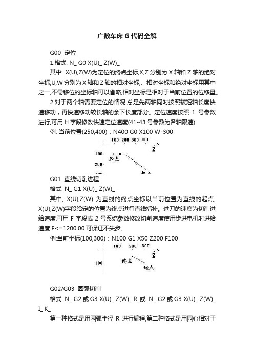
广数车床G代码全解G00 定位1.格式: N_ G0 X(U)_ Z(W)_其中: X(U),Z(W)为定位的终点坐标,X,Z分别为X轴和Z轴的绝对坐标,U,W分别为X轴和Z轴的相对坐标,、相对坐标和绝对坐标用其中之一,不需移位的坐标轴可以省略,相对坐标是相对于当前位置的位移量。
2.对于两个轴需要定位的情况,总是先两轴同时按照较短轴长度快速移动,再快速移动较长轴的余下长度部分。
定位速度按照1号参数进行,可用H字段修改快速定位速度(41-43号参数为各轴限速) 例: 当前位置(250,400):N400 G0 X100 W-300G01 直线切削进程格式: N_ G1 X(U)_ Z(W)_其中, X(U),Z(W) 为直线的终点坐标以当前位置为直线的起点, X(U),Z(W)字段给定的位置为终点进行直线插补。
进刀的速度为切削进给速度,可用F字段或2号系统参数修改切削速度使用步进电机时进给速度F<=1200.00可保证不失步。
例:当前坐标(100,300):N100 G1 X50 Z200 F100G02/G03 圆弧切削格式: N_ G2或G3 X(U)_ Z(W)_ R_或: N_ G2或G3 X(U)_ Z(W)_ I_ K_第一种格式是用园弧半径R进行编程,第二种格式是用园心相对于起点(起点即当前位置)位置(I,K)进行编程。
使用步进电机时进给速度F<=1000.00可保证不失步。
其中, X(U),Z(W) 为园弧终点的坐标;R 园弧的半径;I 园心相对于起点的坐标在X轴的分量, G11状态为直径编程,G10状态为半径编程;K 园心相对于起点的坐标在Z轴上的分量;园弧插补是按照切削速度进刀的。
G2为顺时针方向,G3为逆时针方向,如图示:园弧插补自动过象限,过象限时自动进行反向间隙补偿。
用R 编程时.若R>0,则为小于等于180度的园弧,若R<0则为大于等于180度的园弧。
广数G代码(Gcode)
广数G代码(G code)G code. TXT - you are two boats and you are really beautiful. - everyone who says they don't want to be in love has an impossible person in their heart. I love every unhappy but still smiling child. If there is one person, I am invisible and know that I am waiting for someoneNumerical control lathes can be divided into simple numerical control lathe (economical numerical control lathe),multi-function CNC lathe and CNC turning center according to the function and mechanical composition of numerical control system.(1) simple CNC lathe (economical nc lathe) is a low grade of numerical control lathe, is often done with a single machine or single chip microcomputer control, mechanical part is designed on the basis of the ordinary lathe to improve.(2) the multi-function CNC lathe is also called the all-purpose CNC lathe, which is controlled by a special numerical control system and has the characteristics of nc lathe.(3) the CNC turning center increases the additional coordinate axes on the basis of CNC lathe.Main technical specifications of CNC lathe (CJK6153).The diameter of rotary diameter: phi 530mm. Rotary diameter of the maximum workpiece of the skateboard: 2280mm, the machine tool with the maximum distance of 1000mm, the maximum X direction of the tool frame: 260mm, the maximum z-direction ofthe tool holder: 1000mm. Manual 4 frequency conversion speed control 25 ~ 2000 RPM.4.1.6 numerical control lathe (CJK6153) lubrication and coolingThe lubrication of the machine tool and the lubrication of other parts are two parts. Have the headstock gear adopt oil lubrication, forced by cycloid pump lubrication, cycloidal pump oil absorption, first by the refined filter, and then into a magnetic filter, and then sent to each component of the spindle bearing or effects of oil lubrication and all other moving parts to forced lubrication and oil lubrication. Machine tools in other parts of lubrication, such as tail frame, guide rails and the screw nut adopt oil lubrication, the interval lubrication pump is adopted to X axis and Z axis of the guide surface and the ball screw nut lubrication, tail sleeve cylindrical parts such as automatic intermittent lubrication. In the transparent state tank, with a liquid alarm switch, the machine will lubricate the alarm when the oil in the box is below the regulation value. The machine cooling system adopts pump cooling. The daily maintenance of the cooling unit is mainly the replacement of the cooling water and the cleaning of the filter. It is strictly forbidden to start the cooling pump before the cooling liquid is poured in the cooling box to avoid burning the cooling pump. When cooling water is reduced, supply should be timely. The cooling water should be replaced when the pollution is bad. The cooling liquid should be selected to prevent rust.4.2 programming method of CNC latheIn order to learn the programming of CNC lathe, we must understand the operation point of nc lathe. Most of the existing textbooks do not use CNC lathe operation and programming as a whole.4.2.1 machine coordinate system for CNC latheThe machine tool coordinate system is the inherent coordinate system of the machine tool, it is the foundation for making and adjusting the machine tool, and also the basis of setting the workpiece coordinate system. The machine tool coordinate system has been adjusted before the factory, generally not allowed to change arbitrarily. Reference point is also a fixed limit point on the machine tool, and its position is determined by mechanical block or stroke switch. The machine coordinate system is confirmed by returning the machine zero. Before the machine is turned on, CNC lathe should be familiar with the panel of CNC lathe. The form of the panel is closely related to the numerical control system. It is easy to turn on the CNC lathe. The lathe of the distribution system. When the power is turned on, it is easy to turn on the power supply. After the machine is turned on, the table is returned to the point of origin (or reference point, which has a fixed distance to the origin of the machine tool). The return zero (reference point) step of the CNC lathe is: the switch is in the "back zero" position. Press the manual axis in the direction key + X, + Z to zero indicator light. If the work is not done, the error compensation and backgap compensation will not be realized. Setting the machine tool origin is directly related to the G54 instruction in programming.4.2.Set the workpiece coordinate system of CNC latheThe workpiece coordinate system is the coordinate system used in programming, also called the programming coordinate system, which is artificially set. The establishment of workpiece coordinate system is an indispensable step in nc lathe machining. Different systems have different approaches.1. Establishment method of Siemens 802S system workpiece coordinate system(1) turn the knife to the base knife (e.g. 1 knife).(2) in the MDA state, input T1D0 to make the knife fill 0.(3) machine tool return reference point.(4) use the test method to determine the coordinate origin of the workpiece. The end face of the cutting test. Z doesn't move. If the point is the origin of Z direction, then the zero point of the parameter is placed in the G54 of the directory, and the Z of the point is the negative value of A, that is, Z = -a. If Z goes to the left of the end, then enter Z = - (A +) in G54, return the car. And I'm going to do the same thing with the outer circle. The Z direction is back, and the machine tool coordinates of X direction are recorded, the diameter of the machine is measured, and the radius R is obtained. In the G54 X, input X = -(A + R), return the car.2. The establishment method of the workpiece coordinate system of the GSK980T system(1) use manual method to test the end surface.(2) when the Z axis does not move, the axis is withdrawn along the X-axis and the spindle rotation is stopped. 3. Measuring the distance between the end plane and the zero point of the workpiece coordinate system. Then enter G50 Z in the input method and run the sentence. 4. In the same way, a manual way outside circle, in the case of the X axis fixed return along the Z axis, and stop the spindle rotation, measuring the workpiece diameter X, the entry mode input G50X, run the other can.3. The establishment method of GSK928TC workpiece coordinate system(1) the outer circle of the car, along the z-direction, measured the diameter, enter the diameter value by InputX, enter the car.(2) the end face of the vehicle, along the X direction, the distance between the end and the origin of the work piece, input the distance value by InputZ, and then enter the vehicle.4.2.3 determines the position of the base knife in the work coordinate systemAfter the workpiece coordinate system is determined, the position of the knife (reference knife) in the workpiececoordinate system can be determined by the G50 instruction.4.2.4 determines the location of other knives in the artifact coordinate systemProcessing a parts often need to several different cutting tools, due to the deviation of the tool setting and tool itself every knife to the cutting position, the position of the tip is not coincidence, as users don't need to consider when programming tool, the deviation between need to determine the position of other knife in the workpiece coordinate system, it needs to be through to the knife. Different systems have different approaches to dao.1. Method of Siemens 802S system(1) select a knife as the base knife, press the parameter key and the tool compensation button, then press the new tool button, input the reference knife number and the edge (complement). If the base knife is 1, choose 1 edge (complement), then the cutter is T1D1.(2) call to the knife window, use the base knife car outside circle, Z to return the knife, in the X axis zero deviation of the knife window (because it is the base knife), press the calculation key to confirm.(3) call each other cutter, determine the number of the knife and the edge of the knife, enter the diameter of the outside circle and the end of the car. Enter negative values for the depth of the steps. Calculate and determine.The wide range GSK980T system for the dao(1) use the benchmark tool to test the workpiece, and set the reference frame: test the end face X to return the knife, enter the input mode, press the program button. Enter G50 Z0, which is to use the end face as the z-base level. Then press the set key, set the offset number (the benchmark knife + 100), enter Z = 0, try to cut out the outer circle, Z to the back knife, measure the outer circle diameter, enter the input mode, press the program button. Enter G50X, then press the setting key, setting the partial number, the base knife offset number + 100, X =.(2) call each other cutter, outside circle, Z to return knife. If the diameter of the outer circle is measured, the measured value is set to the one offset, which is the value of the knife number + 100, such as the knife number 2, and the offset number is 202, where X =. Similarly, the steps of the car, X to the back of the knife, the depth of the steps, the input Z = - in the offset sign.3.The wide GSK928TC system for the dao method(1) use the base knife to try to cut the workpiece, use the input to establish the frame of the knife, the Z of the coordinate system is at the origin, generally located at the right end of the workpiece, which is the end of the test cut as Z to the zero.(2) call other knives, such as knife 2, to make a T20 call, then try to cut the outer circle Z to the back of the knife, measure the diameter, and then press the I key. The input. Cut the steps, X to the back, measure the depth of the steps, then press the K key, input - the knife patch is set.4.2.5 axis directionThe direction of the center of the center of the center to the center of the center is the positive direction. The axis perpendicular to the spindle axis in the horizontal plane is the X-axis, and the direction of the rotation center of the spindle is in the positive direction.4.2.6 diameter or radius programmingThe radial dimensions of the processed parts are indicated in the diameter of the drawing and the measurement of processing, so it is more convenient to use diameter size programming.4.2.7 general programming methods1. Determine the location of the first knifeThe g50x Z directive determines the position of the first knife, which requires the first blade to be moved to the position of X Z.2. Return reference pointsG26 (G28) : the X Z axis also returns the reference point, G27:the X axis returns reference point, G29: the z-axis returns reference points.3. Quick positioningG00 X Z quickly locates to the specified point.4. Linear interpolationG01 X Z F is used for outer circle and end surface. F is the feed rate, whose unit is mm/min (specified in G94 or G98) or mm/r (specified in G95 or G99).5. Arc interpolationG02 (03) X Z I K F is used for the car to be rounded or reversed. X Z is the endpoint of the arc, I K is the coordinate of the center relative to the starting point, F is the feed velocity.6. Screw cuttingG33 (32) X Z P (E) I K this instruction for thread cutting, X, Z for threaded end point coordinates, P for metric screw thread (0.25-100 - mm), E for inch screw thread (100-4 teeth per inch), for the refund of the I K. The spindle speed cannot be too high when the thread is cutting, generally N by P is less than 3000, N is the spindle speed (RPM), P is the metric thread guide (mm).7. Delay or pauseG04 X, X is the number of seconds to pause, which is generallyused to cut the slot and keep the bottom smooth.8. Spindle speed settingM03 (04) S is used for the main axis clockwise or counterclockwise, the spindle speed is S, and its unit is m/min (specified by G96) or r/min (specified by G97). The M05 indicates that the spindle stops.9. End of programM02 (end at this point) or M30 (return program first sentence after the end).4.2.8 cycleBecause of the commonly used bar materials and forging materials, the machining margin is larger, which is a simplified programming. The CNC lathe often has different forms of fixed cycle, which can be used for many cyclic cutting.1. Outer diameter and inner diameter cycleG90x Z R F is used for simple turning cycle of external diameter and internal diameter, X Z is the cyclic endpoint coordinates, and R represents the circular cone surface circulation. The value of the cone is the difference of the diameter of the cone, the starting point of the circle is determined by the previous procedure, and F is the feed speed.2. Threading cycle of threadG92 X Z P (E) I K R L, the instruction is used for thread cutting cycle, X, Z for threaded end point coordinates, P for metric screw thread (0.25-100 - mm), E for inch screw thread (100-4 teeth per inch), I K for the refund of, R represents the diameter of the thread starting point and end point (for processing taper thread), L said thread, starting point is determined by the other programs on thread cutting cycle. G92 instructions differ from G33 instructions to G92 multiple automatic cutting threads.Face turning cycleThe G94 X Z R F is used for the simple turning cycle of the end face, X Z is the cyclic endpoint coordinates, and R represents the cone loop. Its value is the size of the cone (Z deviation), and the starting point is determined by the previous program, F is the feed speed.4. Grooving cycleThe G75 X Z I K E F is used to cut the slot loop, X Z is the cyclic endpoint coordinates, and I is the input value per X axis,K is the number of retreats per X axis, E is the offset of Z axis, F is the speed of feed, and the Z is cut off.5. Circular coarse vehicle complex cycleThe G71 X I K L F is used for the outer round coarse vehiclecomplex cycle, which is to write out the shape of the outer circle when the program is programmed. The system starts from the blank to automatically take out the circular shape of the outer circle. The loop cutting, parallel to the Z axis X for circulation coordinates, I for each X amount of feed, K for each X amount of return, L to determine the number of processing procedure in the shape of the cylindrical, F feed speed, G71 instruction period immediately decided to cylindrical shape processing procedures section.6. The end face coarse vehicle complex cycleG72 Z I K L F is used for the end surface rough vehicle complex cycle, which is to write the end surface processing shape when programming, and the system starts automatically out of the end loop shape from the blank. The loop cutting, parallel to the X axis Z for circulation coordinates, I for each Z axis feed quantity, K for the amount of return for each of the Z axis, L to determine the number of end face processing in the shape of a program, F feed speed, G72 instruction period immediately decided to end processing procedures section shape.4.2.9 tool compensationWhen programming, think turning point is a point, but in fact in order to improve the tool life and workpiece surface quality and tool tip into a circular arc radius is often, in order to improve the machining precision of workpiece, round head dao program, need for the tool radius compensation. Most CNC lathes have the automatic tool radius compensation function (G41, G42). This kind of CNC lathe can be programmed directly according tothe contour dimension of the workpiece.4.2.10 absolute coordinates and incremental coordinatesX and Z are absolute coordinates, U and W are relative coordinates.4.2.11 public system and inch size settingThe system size sets the instruction G21, the British system size sets the G20, the machine is in the G21 state after the power is on the system.4.2.12 circular arc to reverse the judgmentThe CNC lathe is a machine tool with two coordinate axes. Only the X and Z axes should be considered by the right hand rule. The positive direction of the Y-axis is pointed to itself in the judgment, (i.e. the negative direction along the Y-axis), and the circular arc of the x-z plane can be correctly judged by standing in such position.CNC lathe programming of typical parts。
m代码g代码大全【超实用】
G代码(G-code,又称RS-274)是广泛使用的数控(numerical control)编程语言,有多个版本,主要在计算机辅助制造中用于控制自动机床。
G代码有时候也称为G编程语言。
而M代码定义为,辅助功能代码。
M代码起到机床的辅助控制作用。
那么G代码有哪些呢?M代码有哪些呢?一起来看看G代码内容G00 快速定位G01 直线插补G02 圆弧插补G03 圆弧插补G04 暂停G13 刀架选择:刀架AG14 刀架选择:刀架BG17 刀具半径补偿:X-Y平面G18 刀具半径补偿:Z-X平面G19 刀具半径补偿:Y-Z平面G20 原始位置指令G21 ATC原始位置指令G22 扭距跳过指令G24 ATC原始位置移动指令(不带直线插补)G25 节点位置移动指令(不带直线插补)G28 扭距极限指令取消G29 扭距极限指令G30 跳步循环G31 固定螺纹车削循环:轴向G32 固定螺纹车削循环:端面G33 固定螺纹车削循环G34 变螺距螺纹车削循环:增加螺距G35 变螺距螺纹车削循环:减少螺距G36 动力刀具轴-进给轴同步进给(正转) G37 动力刀具轴-进给轴同步进给(反转) G40 刀尖圆狐半径补偿: 取消G41 刀尖圆狐半径补偿: 左G42 刀尖圆狐半径补偿: 右G50 零点位移,主轴最高转速指令G52 六角刀架转位位置误差补偿G62 镜像指令G64 到位控制关G65 到位控制开G71 复合固定螺纹车削循环: 轴向G72 复合固定螺纹车削循环: 径向G73 轴向铣槽复合固定循环G74 径向铣槽复合固定循环G75 自动倒角G76 自动倒圆角G77 攻丝复合固定循环G78 反向螺纹攻丝循环G80 形状定义结束(LAP)G81 轴向形状定义开始(LAP)G82 径向形状定义开始(LAP)G83 坯材形状定义开始(LAP)G84 棒料车削循环中改变切削条件(LAP) G85 调用棒料粗车循环(LAP)G86 调用重复粗车循环(LAP)G87 调用精车循环(LAP)G90 绝对值编程G91 增量编程G94 每分进给模式(mm/min)G95 每转进给模式(mm/rev)G96 恒周速切削开G97 G96取消G100 刀架A或刀架B单独切削的优先指令G101 创成加工中直线插补G102 创成加工中圆弧插补(正面) (CW) G103 创成加工中圆弧插补(正面) (CCW) G107 主轴同步攻丝,右旋螺纹G108 主轴同步攻丝,左旋螺纹G110 刀架A恒周速切削G111 刀架B恒周速切削G112 圆弧螺纹车削CWG113 圆弧螺纹车削CCWG119 刀具半径补尝:C-X-Z平面G122 刀架A副主轴W轴指令(13)G123 刀架B副主轴W轴指令(G14)G124 卡盘A有效原点G125 卡盘B有效原点G126 锥度加工模式OFF指令G127 锥度加工模式ON指令G128 M/C加工模式OFF指令G129 M/C加工模式ON指令G132 创成加工中圆弧插补(侧面) (CW) G133 创成加工中圆弧插补(侧面) (CCW) G136 坐标反转结束或Y轴模式关G137 坐标反转开始G138 Y轴模式开G140 主轴加工模式的指定G141 副主轴加工模式的指定G142 自动脱模主轴加工模式的指定G143 自动脱模主轴和第3刀架加工模式的指定G144 W-轴控制OFF指令G145 W-轴控制ON指令G148 B-轴控制OFF指令G149 B-轴控制ON指令G152 可编程尾架定位(牵引尾架)G153 可编中心架G代码(牵引)G154 W-轴单向定位指令G155 精确轮廓描绘模式ON指令G156 精确轮廓描绘模式OFF指令G158 刀具轴方向刀具长度偏移量G159 刀具轴方向刀具长度偏移量(不带旋转位移偏移量) G160 取消刀具轴方向刀具长度偏移量G161 G代码宏功能MODING162 G代码宏功能MODING163 G代码宏功能MODING164 G代码宏功能MODING165 G代码宏功能MODING166 G代码宏功能MODING167 G代码宏功能MODING168 G代码宏功能MODING169 G代码宏功能MODING170 G代码宏功能MODING171 G代码宏功能CALLG178 同步攻丝循环(CW)G179 同步攻丝循环(CCW)G180 动力刀具复合固定循环: 取消G181 动力刀具复合固定循环: 钻孔G182 动力刀具复合固定循环: 镗孔G183 动力刀具复合固定循环: 深孔钻G184 动力刀具复合固定循环: 攻丝G185 动力刀具复合固定循环: 轴向螺纹车削G186 动力刀具复合固定循环: 端面螺纹车削G187 动力刀具复合固定循环: 轴向直螺纹车削G188 动力刀具复合固定循环: 经向直螺纹车削G189 动力刀具复合固定循环: 铰孔/镗孔G190 动力刀具复合固定循环: 键槽切削循环G191 动力刀具复合固定循环: 轴向键槽切削循环G205 G代码宏功能CALLG206 G代码宏功能CALLG207 G代码宏功能CALLG208 G代码宏功能CALLG209 G代码宏功能CALLG210 G代码宏功能CALLG211 G代码宏功能CALLG212 G代码宏功能CALLG213 G代码宏功能CALLG214 G代码宏功能CALLM代码内容M00 程序停止M01 任选停止M02 程序结束M03 工作主轴起动(正转)M04 工作主轴起动(反转)M05 主轴停止M06 刀具交换M08 冷却液开M09 冷却液关M10 主轴点动关M11 主轴点动开M12 动力刀具轴停止M13 动力刀具轴正转M14 动力刀具轴反转M15 C轴正向定位M16 C轴反向定位M17 机外测量数据通过RS232C传送请求M18 主轴定向取消M19 主轴定向M20 尾架干涉区或主轴干涉监视关(对面双主轴规格) M21 尾架干涉区或主轴干涉监视开(对面双主轴规格) M22 倒角关M23 倒角开M24 卡盘干涉区关,刀具干涉区关M25 卡盘干涉区开,刀具干涉区开M26 螺纹导程有效轴Z轴指定M27 螺纹导程有效轴X轴指定M28 刀具干涉检查功能关M29 刀具干涉检查功能开M30 程序结束M32 螺纹车削单面切削模式M33 螺纹车削时交叉切削模式M34 螺纹车削逆向单面切削模式M35 装料器夹持器Z向滑动后退M36 装料器夹持器Z向滑动前进M37 装料器臂后退M38 装料器臂前进到卸载位置M39 装料器臂前进到卡盘位置M40 主轴齿轮空档M41 主轴齿轮1档或底速线圈M42 主轴齿轮2档或高速线圈M43 主轴齿轮3档M44 主轴齿轮4档M48 主轴转速倍率无效取消M49 主轴转速倍率无效M50 附加吹气口1关M51 附加吹气口1开M54 分度卡盘自动分度M55 尾架后退M56 尾架前进M57 M63取消M58 卡盘底压M59 卡盘高压M60 M61取消M61 圆周速度恒定切削时,恒定旋转应答忽视M62 M64取消M63 主轴旋转M码应答忽视M64 主轴旋转之外的M码应答忽视M65 T码应答忽视M66 刀架回转位置自由M67 凸轮车削循环中同步运行模式取消M68 同步模式A运行开M69 同步模式B运行开M70 手动换到指令M72 ATC单元定位在接近位置M73 螺纹车削类型1M74 螺纹车削类型2M75 螺纹车削类型3M76 工件捕手后退M77 工件捕手前进M78 中心架松开M79 中心架夹紧M80 过切前进M81 过切后退M83 卡盘夹紧M84 卡盘松开M85 LAP粗车循环后不返回起始位置M86 刀架右回转指定M87 M86取消M88 吹气关M89 吹气开M90 关门M91 开门M92 棒料进给器后退M93 棒料进给器前进M94 装料器装料M95 装料器卸料M96 副轴用工件捕手后退M97 副轴用工件捕手前进M98 尾架低压M99 尾架高压M100 等待同步指令M101 外部M码M102 外部M码M103 外部M码M104 外部M码M105 外部M码M106 外部M码M107 外部M码M108 外部M码M109 取消M110M110 C轴连接M111 拾取轴自动零点设定M112 M-刀具轴在第三刀架上停止M113 M-刀具轴在第三刀架前进转M114 M-刀具轴在第三刀架向回转M115 卸料器打开M116 卸料器关闭M117 侧头前进M118 侧头后退M119 工件计数专用M120 无工件M121 固定中心架打开/关闭M122 固定中心架后退M123 固定中心架前进M124 STM超时检测开M125 STM超时检测关M126 附加送气口3关M127 附加送气口3开M128 尾架转动后退M129 尾架转动前进M130 卡盘故障检测空气关M131 卡盘故障检测送气输出关M132 卡盘故障检测关M133 卡盘故障检测开M134 负荷监视关M135 负荷监视开M136 复合固定循环形状指定M137 对刀器互锁解除开M138 对刀器互锁解除关M139 自学功能启动M140 攻丝循环动力刀具恒周速应答忽视M141 C轴夹紧指令选择M142 冷却液底压M143 冷却液高压M144 附加冷却液1关M145 附加冷却液1开M146 C轴松开M147 C轴夹紧M148 自动脱模主轴正转M149 自动脱模主轴反转M150 同步旋转关M151 同步旋转开M152 动力刀具轴互锁解除开M153 动力刀具轴互锁解除关M154 附加送气口2关(测量用吹气口) M155 附加送气口2开(测量用吹气口) M156 尾座互锁解除关M157 尾座互锁开M158 凸轮加工机-同步运行关M159 凸轮加工机-同步运行开M160 M161取消M161 进给倍率固定(100%)M162 M163取消M163 动力刀具主轴倍率固定(100%) M164 M165取消M165 进给保持和单程序段忽视M166 尾架进给/后退互锁解除关M167 尾架进给/后退互锁解除开M168 忽略动力刀具轴恒周速应答忽视M169 C轴没卡紧M172 车床内侧机械手互锁解除关M173 车床内侧机械手互锁解除开M174 附加冷却液2关M175 附加冷却液2开M176 Y轴松开M177 Y轴夹紧M178 尾架卡盘夹紧M179 尾架卡盘松开M180 机械手请求0M181 机械手请求1M182 机械手请求2M183 机械手请求3M184 卡盘互锁取消关M185 卡盘互锁取消开M188 尾架连接关(牵引可编程尾架规格)M189 尾架连接开(牵引可编程尾架规格)M190 尾架连接是可用G00移动M191 动力刀具主轴分度方向指定(顺时针)M192 动力刀具主轴分度方向指定(逆时针)M193 M194取消M194 螺纹车削相位核运行M195 M196取消M196 螺纹车削相位核对位移量有效M197 螺纹车削相位核对位移量清除M200 Z轴同步进给取消M201 Z轴同步进给G13M202 Z轴同步进给G14M203 刀架松开(数控刀架)M204 LR15M-ATC;循环时间缩短规格(刀库换刀门关)M205 LR15M-ATC;循环时间缩短规格(刀库换刀门开)M206 LR15M-ATC;循环时间缩短规格(后退位置防护罩开) M207 LR15M-ATC;循环时间缩短规格(后退位置防护罩关)M208 门互锁C,D开M209 门互锁C,D关M211 键槽切削循环:单向切削模式M212 M-刀具轴在第三刀架上停止或键槽切削循环:交叉切削模式M213 M-刀具轴在第三刀架上停止或键槽切削循环:进给量指定切削模式M214 M-刀具轴在第三刀架上停止或键槽切削循环:等分切削模式M215 负载监视G00忽略关M216 负载监视G00忽略开M218 附加吹气口关M219 附加吹气口开M220 平面车削关M221 平面车削旋转比(1:1)M222 平面车削旋转比(1:2)M223 平面车削旋转比(1:3)M224 平面车削旋转比(1:4)M225 平面车削旋转比(1:5)M226 平面车削旋转比(1:6)M227 LR15M-ATC;ATC操作完成等待指令M228 ATC下一个刀具返还指令M229 ATC动力刀具分度M230 外部M码M231 外部M码M232 外部M码M233 外部M码M234 外部M码M235 外部M码M236 外部M码M237 外部M码M238 平面车削动力主轴相位变更M239 副主轴模式主轴分度M240 动力刀具主轴:空档M241 动力刀具主轴:第1档M242 动力刀具主轴:第2档M243 排屑装置停止M244 排屑装置正转M246 副主轴卡盘互锁解除开M247 副主轴卡盘互锁解除关M248 副主轴卡盘夹紧M249 副主轴卡盘松开M250 工件推进器后退M251 工件推进器前进M252 激光尺数据写入M253 激光尺数据核对M254 程序停止M264 M265取消M265 脉冲手轮控制方式是取消快速进给M271 主轴低速开M272 主轴低速关M288 副主轴模式吹气关M289 副主轴模式吹气开M290 顶门关M291 顶门开M296 时间常数切换(用于少量切削标志) M297 时间常数切换(用于有效形状)。
广数g代码(WidenumberGcode)
广数g代码(Wide number G code)G code.Txt - you pedal two boats, you row really beautiful. Every man who says he doesn't want to be in love has an impossible man in his heart. I love every unhappy but still laughing child. (there is no one, see through me, invisible, know I'm waiting for someone). Classification of 4.1.4 CNC lathesCNC lathes vary in variety, according to CNC system functions and mechanical composition, can be divided into simple CNC lathe (economic CNC lathe), multi-function CNC lathe and CNC turning center.(1) simple numerical control lathe (economical CNC lathe) isa low grade CNC lathe. It is controlled by single board machine or single chip microcomputer. The mechanical part is improved on the basis of ordinary lathe.(2) multi function CNC lathe, also known as fully functional CNC lathe, is controlled by a special CNC system, and has various structural characteristics of CNC lathes.(3) CNC turning centers add additional coordinate axes on the basis of NC lathes.Main technical specifications of 4.1.5 CNC lathe (CJK6153).The maximum diameter: 530mm diameter rotary tool. Skateboard maximum workpiece diameter rotary: 280mm diameter, top machine from 1000mm, X to the maximum knife stroke: 260mm, maximum Z to knife stroke: 1000mm. Manual 4 stage variable frequencyspeed regulation, 25~2000 turn / minute.Lubrication and cooling of 4.1.6 numerical control lathe (CJK6153)The two part lubrication of the machine into the headstock rengar and other parts. The gear changing headstock is oil lubricated, forced lubrication by the cycloidal pump, and through the refining filter, when the cycloidal pump pumps oil,Then enter the magnetic filter, and then sent to the lubrication parts, or through the oil distributor on the spindle bearings and all other running parts forced lubrication and fuel injection lubrication. Other parts of the machine tool lubrication, such as tailstock, rail and screw nut are lubricated by oil, the use of intermittent lubrication pump automatic intermittent lubrication of X axis and Z axis of the guide rail and ball screw nut, lubricating the surface of tailstock sleeve and other parts of the outer circle. In the transparent tank, there is a liquid level alarm switch. When the oil in the tank is below the specified value, the machine will issue a lubrication alarm. The cooling system of the machine adopts pump cooling. The daily maintenance of cooling equipment is mainly cooling water supply, replacement and filter cleaning. The cooling pump is not allowed to start before the coolant is inserted into the cooling box, so as not to cause the cooling pump to burn out. When cooling water is reduced, supplies should be made in time. When cooling water is polluted, it should be replaced completely. The cooling liquid should be chosen to prevent rust.4.2 programming method of NC latheIn order to master the programming of NC lathe, it is necessary to understand the operation points of NC lathe. Most of the existing teaching materials do not regard the operation and programming of NC lathe as a whole.4.2.1 sets the machine tool coordinate system of NC latheThe coordinate system of machine tools is the inherent coordinate system of machine tools. It is the basis of manufacturing and adjusting machine tools, and also the basis of setting up the coordinate system of workpieces. The machine tool coordinate system has been adjusted before leaving the factory and is not allowed to change at will. The reference point is also a fixed limit point on the machine tool. Its position is determined by a mechanical block or a travel switch. Confirm the machine coordinate system by returning the machine zero.Back to the machine before the start of zero, CNC lathe boot before you should be familiar with CNC lathe panels. The form of panel is closely related to CNC system. CNC lathe boot difficult and easy?. For the production system of the lathe with pictures. Most of the boot is relatively simple, generally open the power supply, directly start the CNC system can be. After starting the machine, by returning zero, the worktable is returned to the original point of the machine (or reference point, which is a fixed point from the origin of the machine tool). The step of zero return of NC lathe is that the switch is placed back to zero. Press the manual shaft feed key +X, +Zto zero, the indicator light. After starting the machine, you must first return the zero (back to the test center), and if you do not do this work, then the pitch error compensation, backlash compensation and other functions will not be achieved. Setting the machine machine origin is directly related to the G54 instructions in the program.4.2.2 setting the workpiece coordinate system of NC latheThe workpiece coordinate system is the coordinate system used in programming, also known as the programming coordinate system. The coordinate system is artificially set. Setting up the workpiece coordinate system is an essential step before NC lathe machining. Different systems have different methods.1. establishment method of workpiece coordinate system of SIEMENS 802S system(1) turn the tool holder to the reference knife (such as cutter No. 1).(2) in the MDA state, enter T1D0, so that the knife complement is 0.(3) machine tool back reference point.(4) determine the origin of workpiece coordinates by trial cutting. The end face of the cutting specimen. Z the direction is still. If the point is the origin of the Z direction, the zero point under the parameter is offset in the G54 of the directory, and the Z of the point is input to the negative valueof the mechanical coordinate value A, or Z=-A.If Z is to the origin at the left end of the end, enter Z=- (A+) in the G54 and enter the carriage. Similarly, try cutting the outer circle and the X direction is not moving. Z direction retract, write down the machine coordinate A in X direction, measure the diameter, get the radius R, enter X=- (A+R) in the G54 of X, and return the car.Construction method of workpiece coordinate system of 2. wide number GSK980T system(1) test the end face by hand.(2) when the Z axis is not moving, return the knife along the X axis and stop the spindle rotation. 3. measuring the distance between the end face and the zero of the workpiece coordinate system Z. Then enter G50 Z in the input mode and run the sentence.4., the same way, manually use the car outside the circle, in the X axis is not moving, along the Z axis back, and stop spindle rotation, measuring workpiece diameter X, in the input mode input G50X, run the sentence can.Construction method of 3. wide number GSK928TC workpiece coordinate system(1) the outside of the car, along the Z to return the knife, measured diameter, press InputX enter diameter value, enter the car can.(2) the end of the car, along the X to return the knife,measuring the end of the workpiece coordinates and the origin of the distance between, and press InputZ enter the distance value, enter the car can.4.2.3 determines the position of the reference tool in the workpiece coordinate systemAfter the workpiece coordinate system has been determined, the position of the first cutter (reference knife) in the workpiece coordinate system can be determined by using the G50 instruction.4.2.4 determines where other knives are located in the workpiece coordinate systemA parts processing often requires several different cutting tools, cutting tool installation and the deviation of the tool itself, each knife to the cutting position, its tip position does not coincide, for users in programming without considering the deviation between the tool,The location of other knives in the workpiece coordinate system must be determined, which needs to be achieved by tool setting. Different systems have different tool setting methods.1., SIEMENS 802S system tool setting method(1) select a knife as the reference knife, press the parameter key and the tool compensation button, then press the new tool button, enter the reference knife's knife number and the knife edge (repair) number. For example, the standard knife is No.1, and the No. 1 knife edge is used (cutter), and the cutter is T1D1.(2) call the tool setting window, use the reference cutter, the outer circle and the Z to retract the knife, and enter 0 at the zero offset of the X axis of the tool window (because it is a reference knife), then press the calculation key to confirm it.(3) call each other tool, determine the cutter number and edge (patch) number, the input diameter of the outer circle and the end face of the vehicle. Enter the negative value of the step depth. Calculate and confirm.Tool setting method of 2. wide number GSK980T system(1) cutting the workpiece with the reference knife, setting the reference coordinate system: cutting the end face X, returning the knife, entering the input mode, pressing the program button. Enter G50 Z0, that is, the end face as Z to the base plane. Then press the settings button, set the offset number (reference knife +100), enter Z=0, try cutting the outer circle, Z to the knife, measure the diameter of the outer circle, enter the entry mode, press the program button. Enter G50X, and then press the settings button to set the offset number, the reference knife offset number +100, X=.(2) call each other tool, the outer circle of the car and the Z to return the knife. Measure the diameter of the outer circle and set the measured value to an offset number. The offset is +100. If the number is 2, the offset number is 202. Enter X= here. In the same way, the step of the car and the X retractthe knife to measure the depth of the step,Enter Z=- at the offset number.Tool setting method of 3. wide number GSK928TC system(1) cutting the workpiece with the reference cutter, and setting up the cutter coordinate system with input. The coordinate system is Z to the origin, which is usually located at the right end of the workpiece, that is to say, the cut end face is taken as Z zero.(2) call other knives, such as 2 knives, call with T20, and then try to cut the outer circle, Z, retract the knife, measure the diameter, and press the I key. Input. Try cutting the steps, X to the knife, measuring the depth of the step, and then press the K key, input -, the knife is set up.The direction of the 4.2.5 coordinate axisEither coordinate system specifies that the axis parallel to the spindle axis of the lathe is the Z axis, and the center of the center from the center of the chuck to the tailstock is in the positive direction. In the horizontal plane, the direction perpendicular to the axis of the lathe spindle is X axis, and the direction of the rotation center away from the main shaft is in the positive direction.4.2.6 diameter or radius dimensions are programmedThe radial dimension of the machined part is usually indicatedby the diameter value in the process of drawing and processing. Therefore, it is more convenient to program with diameter.4.2.7 general programming method1. make sure the location of the first knifeG50 X Z, this command determines the position of the first knife, at which point the first knife is moved to the workpiece coordinates of X Z.2. returns the reference pointG26 (G28): the X Z axis returns the reference point at the same time, the G27:X axis returns the reference point, and the G29:Z axis returns the reference point.3. fast positioningG00 X Z, quick to locate the specified point.4. linear interpolationG01 X Z F, this instruction is used for the outer circle and end face of car. F is the feed rate,其单位为mm / min (用g94或g98指定) 或mm / r (用g95或g99指定).5.圆弧插补g02 (03) x z in k f 该指令用于车顺圆或逆圆周.x z为圆弧终点坐标, in k为圆心相对于起点的坐标, f为进给速度.6.螺纹切削g33 (32) x z p (e) in k 该指令用于螺纹切削, x z为螺纹终点坐标, p为公制螺纹导程 (0.25-100mm), e为英制螺纹导程 (100 - 4牙 / 英寸), in k为退尾数据.螺纹切削时主轴转速不能太高, 一般n×p≤3000, n为主轴转速 (rpm), p为公制螺纹导程 (mm).7. 延时或暂停g04 x, x为暂停秒数, 该指令一般用于切槽, 可保持槽底光滑.8.主轴转速设定m03 (04) 该指令用于主轴顺时针或逆时针转, 主轴转速为s, 其单位为m / min (用g96指定) 或r / min (用g97指定).m05表示主轴停止.9.程序结束m02 (在此处结束) 或m30 (结束后返回程序首句).4.2.8 循环由于车削加工常用棒料和锻料作为毛坯, 加工余量较大, 为简化编程, 数控车床常具备不同形式的固定循环, 可进行多次循环切削.1. 外径、内径循环g90 x z r f 该指令用于外径、内径的简单车削循环, x z为循环终点坐标, r表示圆锥面循环.其值为圆锥体大小端差 (直径差), 循环起点由上句程序决定,F is the feed rate.2. thread turning cycleG92 X Z P (E) I K R L the instructions for thread turning cycle, X Z P as the end point coordinate thread, metric thread lead (0.25-100mm), E (100-4 inch thread lead tooth / inch) K, I back tail data, R said the starting point and end point thread diameter difference (used for machining taper thread), L said the thread number, thread turning cycle starting point determined by the procedure. The difference between the G92 instruction and the G33 instruction is that the G92 can automatically cut threads many times.3. end turning cycleG94 X Z R F. This instruction is used for the simple turning cycle of the end face. The X Z is the loop end point coordinate, and the R represents the cone cycle. Its value is the size of the cone, the end difference (Z to the difference), the starting point of the cycle is determined by the previous sentence procedure, and the F is the feed rate.4. groove cycleG75 X Z I K E F the instructions for cutting cycle, X Z cycle end point coordinates, I for the amount of feed each X axis,K axis X knife back every time, every time the E for the Z axis offset, F feed rate, Z said cut off.5., outer circle, rough car, compound cycleG71 X I K L F this instruction is used in the outer circle rough vehicle compound cycle, namely when programming writes the excircle processing shape, the system starts from the semifinished material to go out automatically the outer circle shape. The loop is parallel to the Z axis cutting, X circular end point coordinates, I for the amount of feed each X axis, K axis X knife back every time, L decided to program process of cylindrical shape quantity, F velocity, G71 program instruction segment immediately after the decision process of cylindrical shape of the ground.6. end rough vehicle combined cycleG72 Z I K L F this instruction is used in the end face rough vehicle compound cycle, namely when programming writes the end surface processing shape, the system starts from the semifinished material to go out automatically the end face cycle shape. The loop is parallel to the X axis cutting, Z circular end point coordinates, I for the amount of feed each Z axis, K axis Z knife back every time, L decided to end processing program segment shape quantity, F velocity, G72 program instruction segment immediately after the decisions end processing shape.4.2.9 tool compensationWhen programming, that the turning point is a point, but in fact in order to improve tool life and surface quality of the workpiece, tool nose often ground into a small circular arc radius, in order to improve the machining precision of the workpiece, preparation of round knife program, need to compensate for the tool radius. Most CNC lathes have automatic tool radius compensation (G41, G42), which can be programmed directly according to the outline dimensions of the workpiece.4.2.10 absolute coordinates and incremental coordinatesX and Z represent absolute coordinates, and U and W represent relative coordinates.4.2.11 metric and inch size settingThe metric size setting instruction G21, the grandfather size setting instruction G20, and the system is powered on, the machine is in the G21 state.The judgement of the arc of 4.2.12CNC lathe is a two coordinate machine tool, only the X axis and Z axis, the right hand rule should be based on the Y axis is also added to consider. When judging, let the positive direction of the Y axis point to itself, that is, to look in the negative direction of the Y axis. Standing in such a position, the clockwise and counterclockwise clockwise of the arc on the X-Z plane can be correctly judged.4.3. typical parts NC lathe programming example。
- 1、下载文档前请自行甄别文档内容的完整性,平台不提供额外的编辑、内容补充、找答案等附加服务。
- 2、"仅部分预览"的文档,不可在线预览部分如存在完整性等问题,可反馈申请退款(可完整预览的文档不适用该条件!)。
- 3、如文档侵犯您的权益,请联系客服反馈,我们会尽快为您处理(人工客服工作时间:9:00-18:30)。
广数G代码
代码功能
G00 快速定位
G01 直线插补
G02 顺时针圆弧插补
G03 逆时针圆弧插补
G04 暂停、准停
G05 三点圆弧插补
G6.2 顺时针椭圆插补
G6.3 逆时针椭圆插补
G7.2 顺时针抛物线插补
G7.3 逆时针抛物线插补
G10 数据输入方式有效
G11 取消数据输入方式
G20 英制单位选择
G21 公制单位选择
G28 自动返回机械零点
G30 回机床第2、3、4参考点G31 跳转插补
G32 等螺距螺纹切削
G33 Z 轴攻丝循环
G34 变螺距螺纹切削
G36 自动刀具补偿测量X
G37 自动刀具补偿测量Z
G40 取消刀尖半径补偿
G41 刀尖半径左补偿
G42 刀尖半径右补偿
G50 设置工件坐标系
G65 宏代码
G66 宏程序模态调用
G67 取消宏程序模态调用
G70 精加工循环
G71 轴向粗车循环
G72 径向粗车循环
G73 封闭切削循环
G74 轴向切槽循环
G75 径向切槽循环
G76 多重螺纹切削循环G90 轴向切削循环
G92 螺纹切削循环
G94 径向切削循环
G96 恒线速控制
G97 取消恒线速控制G98 每分进给
G99 每转进给。
