CS8182YDF8中文资料
V8A02解决方案用户手册V2.1

V8A02解决方案用户手册V2.1目录1. 文档说明 (6)1.1版本说明 (6)1.2专有名词 (6)2. 方案简介 (8)2.1方案概述 (8)2.2 功能特点 (8)2.2.1 支持DVI数据源输入 (8)2.2.2 支持宽屏等多种DVI输入分辨率 (8)2.2.3 发送卡超大带载 (8)2.2.4 功能强大的配套软件 (8)2.2.5 智能在线检测 (8)2.2.6 高刷新频率 (8)2.2.7 高灰度等级 (9)2.2.8 支持各种像素类型 (9)2.2.9 灵活支持各种模组 (9)2.2.10 多样的端口设置功能 (9)2.2.11箱体色度调整 (9)2.2.12 逐点校正功能 (9)2.2.13 集成测试功能 (9)2.2.14 联机配置数据 (9)2.2.15 智能维修 (10)2.2.16 环路备份功能 (10)2.2.17 在线升级固件安全可靠 (10)2.2.18 支持低电压输入 (10)2.2.19 配备指示灯及控制面板接口 (10)2.2.20 支持远距离传输 (10)2.2.21 支持音频传输及电源控制 (10)2.2.22 提供完整的二次开发接口 (10)2.2.24 支持内建PWM恒流 (10)2.2.25 支持低亮度高保真 (10)2.3产品清单 (11)3. 应用概述 (12)3.1 典型应用 (12)3.2 环路备份 (13)3.3 多发送卡 (14)4. 功能详解 (15)4.1 模组支持能力 (15)4.1.1 模组行、列数1~128以内任意 (16)4.1.2 模组数据类型 (16)4.1.3 模组内每扫描串移长度 (17)4.1.4 虚拟模组LED灯点位置多种排列方式 (17)4.2 箱体连接设置 (17)4.2.1 箱体内模组级联方式 (17)4.2.2 端口扩展 (18)4.2.3 端口对开 (19)4.2.4 端口逆序 (20)4.2.5 端口偏移 (20)4.2.6 箱体带载高度、宽度 (20)4.2.7 箱体显示起始的行、列位置 (21)4.2.8 箱体无信号输入时显示内容设置 (21)4.2.9 箱体级联数量 (21)4.2.10 箱体色度调整 (21)4.2.11 箱体逐点色度校正 (22)4.2.12 箱体测试功能 (22)4.3 屏体参数调节 (23)4.3.1 多个LED屏设置 (23)4.3.3 虚拟LED屏的实效果 (24)4.3.4 LED屏亮度调节 (25)4.3.5 LED屏对比度调节 (26)4.3.6 LED屏色温调节 (26)4.3.7 关闭LED屏显示 (27)4.3.8 锁定LED屏内容 (27)4.3.9 LED屏环境监控 (27)4.4 显示性能参数说明 (30)4.4.1 灰度等级 (30)4.4.2 刷新频率 (31)4.4.3 亮度效率 (31)4.4.4 最小OE (31)4.5 发送卡带载 (31)4.6 在线检测 (34)4.7 系统升级 (34)4.8 智能维修 (36)4.8.1 接收卡更换 (36)4.8.2模组替换 (37)5. 使用说明 (39)5.1 连接硬件 (39)5.1.1 发送卡安装方法 (39)5.1.2 接收卡安装方法 (39)5.1.3 多功能卡安装方法 (39)5.2 安装软件 (40)5.2.1 配置要求 (40)5.2.2 安装步骤 (40)5.3 系统设置 (40)5.3.1 显卡设置 (40)5.3.2系统设置 (43)6. 附录 (55)6.1 设备推荐型号 (55)6.1.1 DVI复制器 (55)6.2 选用线缆清单 (55)6.2.1 HDMI转DVI线缆 (55)6.2.2 音频线 (56)6.2.3 双绞线 (56)6.2.4 光纤 (56)1. 文档说明1.1版本说明版本日期说明V2.0 2013-01-09 升级自1.71版本V2.1 2013-07-15 新增接收卡产品1.2专有名词以下是本文中使用的专用术语及解释,便于读者更好的理解文章内容。●软件一系列按照特定顺序组织的计算机数据和指令的集合,本文中特指在计算机上运行的应用软件。
TP5128_Datasheet

非隔离降压型LED驱动器概述TP5128是一款专用于LED非隔离降压型恒流驱动集成电路,系统工作在谷底开关模式,转换效率高,EMI低,PF可调节至0.9,输出电流自动适应电感的感量变化和输出电压的变化,从而真正实现了恒流驱动LED。
TP5128内部集成500V功率的MOSFET,采用DIP8封装,输出高达360mA的电流,外围只需要很少的器件就可以达到优异的恒流输出。
TP5128内部集成了丰富的保护功能,包括过压保护,短路保护,逐周期电流保护,温度保护和软启动等。
TP5128采用智能热响应抑制技术,自动抑制LED灯的系统温升。
TP5128具有极低的启动电流和工作电流,可在全电压交流输入(85VAC-265VAC)范围内高效驱动LED。
管脚排列特点●内置500V功率MOSFET●无需辅助线圈供电,外围元件少●DIP8封装,输出电流可高达360mA●谷底开关,高效率,低EMI●PF 可调节至0.9●自动补偿电感的感量变化●自动适应输出电压变化●短路保护●温度保护●过压保护/开路保护●智能热响应抑制,自动抑制LED灯的系统温升●即开即亮启动技术●工作温度:- 40 ~ 100℃●封装:DIP8应用范围LED照明--非隔离降压型LED驱动器管脚描述极限参数电气参数(除非特别注明,TA=25℃)非隔离降压型LED 驱动器功能框图非隔离降压型LED 驱动器应用信息TP5128是非隔离降压型恒流驱动集成电路,内部集成高压500V 的MOSFET,采用DIP8封装,LED 电流可以输出高达360mA ,TP5128采用谷底开关模式,自适应电感感量和输出电压的变化,只需要很少的外围器件来实现恒流驱动 LED 。
芯片启动和供电TP5128工作电流小,由母线通过启动电阻直接给芯片供电。
采样电阻TP5128是一款专用于 LED非隔离降压型控制器,系统工作在谷底开关模式,只需要很少的外围器件即可实现高精度的恒流输出。
芯片逐周期的检测电感上的峰值电流,CS 端连接芯片内部,并与内部基准电压VREF 进行比较,当 CS 达到内部阈值时,系统会关掉内部功率管。
MHW8182A中文资料
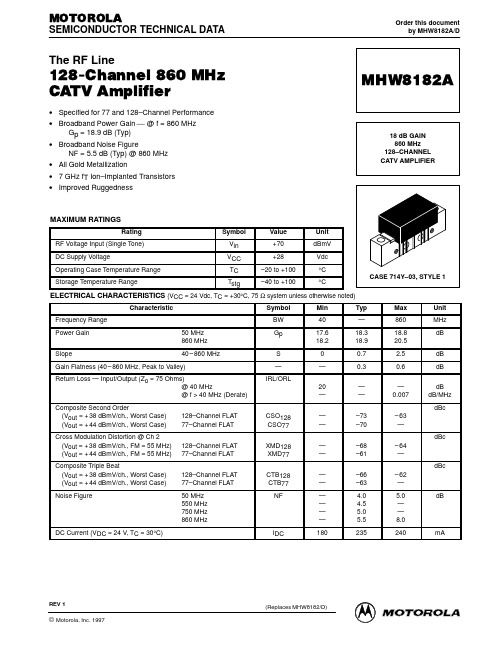
ELECTRICAL CHARACTERISTICS (VCC = 24 Vdc, TC = +30°C, 75 Ω system unless otherwise noted)
Characteristic Frequency Range Power Gain Slope 50 MHz 860 MHz 40 – 860 MHz Symbol BW Gp S — IRL/ORL 20 — CSO128 CSO77 XMD128 XMD77 CTB128 CTB77 NF — — — — — — — — — — 180 — — –73 –70 –68 –61 –66 –63 4.0 4.5 5.0 5.5 235 — 0.007 – 63 — dBc 128–Channel FLAT 77–Channel FLAT 128–Channel FLAT 77–Channel FLAT 50 MHz 550 MHz 750 MHz 860 MHz – 64 — dBc – 62 — 5.0 — — 8.0 240 dB dB dB/MHz dBc 128–Channel FLAT 77–Channel FLAT Min 40 17.6 18.2 0 — Typ — 18.3 18.9 0.7 0.3 Max 860 18.8 20.5 2.5 0.6 Unit MHz dB dB dB
DC Current (VDC = 24 V, TC = 30°C)
IDC
mA
REV 1
(Replaces MHW8182/D)
RF DEVICE DATA ©MOTOROLA Motorola, Inc. 1997
MHW8182A 1
元器件交易网
PACKAGE DIMENSIONS
GS8180S18资料

Functional Description
Because a Sigma RAM is a synchronous device, address, data Inputs, and read/ write control inputs are captured on the rising edge of the input clock. Write cycles are internally self-timed and initiated by the rising edge of the clock input. This feature eliminates complex off-chip write pulse generation required by asynchronous SRAMs and simplifies input signal timing.7 A(8M)
8 E3 MCL NC NC VDDQ VSS VDDQ VSS VDDQ NC VDDQ VSS VDDQ VSS VDDQ NC A A TDO
9 A NC MCL VSS VDDQ VSS VDDQ VSS VDDQ NC VDDQ VSS VDDQ VSS VDDQ VSS NC A
333 MHz 1.8 V VDD 1.8 V and 1.5 V I/
Features
• Observes the Sigma RAM pinout standard • 1.8 V +150/–100 mV core power supply • 1.5 V or 1.8 V I/O supply • Pipelined read operation • Fully coherent read and write pipelines • Echo Clock outputs track data output drivers • ZQ mode pin for user-selectable output drive strength • 2 user-programmable chip enable inputs for easy depth expansion • IEEE 1149.1 JTAG-compatible Boundary Scan • 209-bump, 14 mm x 22 mm, 1 mm bump pitch BGA package • Pin compatible with future 32M, 64M and 128M devices - 333 3.0 ns 1.5 ns
八路遥控(无线)开关
图 3. 晶振电路与复位电路
其次是控制端单片机上连接的开关部分,本次设计要求是八路无线远程开 关,所以我用了八个开关,因为要控制两片编码芯片,如果用一组 I/O 口控制起 来会非常麻烦,I/O 端口是 CPU 与外部设备、存储器的连接和数据交换的接口。 在 AT89C1 单片机上有 32 个 I/O 口,分为四组,分别是 P0,P1,P2 和 P3,每 组 I/O 口可以发送 8 位二进制数。所以这里我用到了两组 I/O 口 P1 和 P3。八个 开关分别连接单片机的 P1.0~P1.3 口以及 P3.4~P3.7 口,前四个开关控制的是 P1.0~P1.3 口,通过单片机传到 P2 的前四个口,以达到控制第一片 PT2262 编码 芯片的功能;后四个开关控制的是 P3.4~P3.7 口,通过单片机传到 P2 的后四个 口,以达到控制第二片 PT2262 编码芯片的功能;P1 口数据会传到第一片编码芯
1
对于本设计要求,需采用 315MHz 无线模块,实现 1km 范围内 8 路开关的 无线远程控制。 在电路设计好的基础上将原理图用相应软件画出来,并做出相应 的仿真,得出仿真结果。 二、方案论证 方案一: 第一种方案是采用实际单独硬件整合搭配后实现八路无线遥控的功能。其 中,需要把八个开关的闭合状态分别编码,用到 PT2262 芯片编码,在编码之后 需要通过无线发送装置发射出去,再由无线接收装置接收到信号后将信号传给 PT2272 芯片译码器,通过译码器将信号解码得到最终编码,传给被控制的部分 完成控制功能,实现了控制八个无线遥控开关的功能。 这种方法在控制少路开关时比较简单易行,因为 P2262 和 P2272 芯片的输 入端口只有 6 个,但是要控制八个端口的开关就需要两组 P2262 和 P2272 芯片, 这样组合后, 要完成八路控制功能就变得不好实现了。首先面临解决的问题是两 组芯片的选择问题, 其次就是当多路开关按下时, 无线口输出端的数据冲突问题, 最后还有无线接收端的数据冲突问题。 要解决这些问题,就需要用到多个门电路,555 延时芯片,编码器,译码器 和数据锁存器等元件,如果在实际中实现功能会比较麻烦,元件越多出现错误率 就越高。 既然在硬件方面难以实现八路无线遥控开关的功能,我便想到了用软件 的方式实现。既然想到用到了软件来实现,那就必然要用到单片机。于是便产生 了第二个方案。 方案二: 现在正是单片机盛行的时候,我们的很多家用电器其中都有用一块或者多块 单片机组成的不同功能的电路模块,单片机的使用,方便了电路的开发者,将原 本需要很大空间和时间搭建的电路图集成起来,只需往其中烧入程序,就能控制 整个电路。 而在实现本次课程设计中八路遥控开关控制电路中,也可以用到单片机,那 就变得简单易行了,而且这样的电路需要的单片机不会太复杂,利用我们所学的 80C51 单片机就能都够实现。 将每一个开关编好地址,再控制其地址就可以了;其中遥控部分采用常用的 315 兆赫兹频率发射器,通过 PT2262 芯片将其编码发射,接收端采用 PT2272 芯片接收译码,实现控制功能。 所以在选择方案是我选择了用单片机的方式实现。用软件程序代替硬件门电 路选择,延时,中断等功能。
最新BESC-8182新伺服控制器说明书汇总

B E S C-8182新伺服控制器说明书-………………………………………………概述 (2)-型伺服控制器外形 (2)-型伺服控制器结构 (2)主要的技术参数和性能指标 (3)选型定义 (3)………………………………………………………系统组成 (4)工作原理 (4)………………………………………………………控制功能 (5)本地控制功能 (5)报警功能 (5)指令信号丢失报警功能 (5)反馈信号丢失报警功能 (5)显示功能 (5)……………………………………………………安装 (7)接线 (7)指令信号 (7)变送器 (7)伺服阀 (8)位置输出 (8)信号丢失 (9)反馈丢失 (9)24V电源线 (9)机壳 (9)……………………………………………………………控制器跳线设定 (10)实际位置的调节 (10)…………………………………………………………概述B E SC -8182型伺服控制器主要适用于TRT 压差发电阀门控制、透平机静叶角度控制以及其它相关的电液执行机构的伺服控制。
控制器接收指令信号及反馈信号经过运算及功率放大后送出控制信号控制伺服阀,同时提供指令信号丢失、反馈信号丢失报警功能及4~20mA 阀位指示信号。
同时可通过控制器前面板的显示器显示其工作参数和工作状态,使调试和纠错工作更加简便。
BESC-8182型伺服控制器外形BESC-8182型伺服控制器外形尺寸图BESC-8182型伺服控制器结构控制器由标准工业机箱、主控制单元、输出接口板、输入指示板和前面板组成。
前面板装有:(1)控制器的电源开关,打开开关控制器即可进入工作状态;(2)本地给定调节电位器,在控制器处于本地模式下,可以通过该电位器调节伺服阀;(3)本地/远程切换开关,用于切换控制器的工作模式;(4)通讯接口用于对控制器参数进行修改和故障诊断;(5)端子排,用来连接控制器的信号线。
具体接线方法请参见后面有关章节的详细叙述;(6)数字显示器,用于显示控制148mm器的工作参数,根据显示模式选择可以显示远程给定信号(%)、本地给定信号(%)、阀位反馈信号(%)、伺服阀实际电流(mA)、设定信号与阀位反馈信号的偏差(%);(7)显示模式选择按钮和显示模式指示灯,用于选择数字显示器上显示的内容,按下与名称对应的按钮,相应的指示灯亮,此时数字显示器上显示相应的数值;(8)控制器状态指示灯,用于指示控制器目前的工作状态;主要的技术参数和性能指标●指令输入信号: 4~20mA(输入阻抗200 Ω)●反馈输入信号: 4~20mA(输入阻抗250 Ω)●输出电流: Ⅰ型:4mA~20mA(负载阻抗200 Ω) ,Ⅱ型:-60mA~60mA(可调)●阀位指示电流: 4~20mA(负载阻抗≤500 Ω)●调节分辨率:优于0.1%●显示分辨率:±1/2 LSB●线性度:优于0.1%●重复性:优于0.1%●工作电源: 24VDC±10%,0.6A●工作环境温度: 0℃~+40℃●外形及尺寸: 380×330×148mm●重量:约3.8Kg选型定义系统组成及工作原理系统组成控制器组成的伺服控制系统简图工作原理实际工作中,传感器ZE用来测量实际位置(或速度等)信号,并将其转换成对应的电信号送至BESC-8182伺服控制器作为反馈信号。
CS8182YDF8,CS8182YDF8G,CS8182DTG,CS8182YDFR8G,CS8182YDFR8G, 规格书,Datasheet 资料

ESD Capability (Human Body Model) (Machine Model)
45 −10 to +VIN
25 80
4.0 48
Control
• These are Pb−Free Devices
VIN
VOUT
Current Limit & SAT Sense
8 1
SO−8 DF SUFFIX CASE 751
1
5 D2PAK−5 DPS SUFFIX CASE 936AC
1 5
DPAK−5 DT SUFFIX CASE 175AA
−65 to +150
°C
Junction Temperature
+150
°C
Supply Voltage Range (Continuous)
−16 to 45
V
Peak Transient Voltage (VIN = 14 V, Load Dump Transient = 31 V)
Voltage Range (Adj, VOUT, VREF/ENABLE)
PIN CONNECTIONS AND
MARKING DIAGRAMS
1
8
VOUT GND
GND Adj
8182 ALYW
G
VIN GND
GND VREF/ENABLE
CS 8182 AWLYWWG
Tab GND
Pin 1. VIN 2. VOUT 3. GND
STAUBLI机器人CS8C 型控制器

CS8C型控制器电路手册D2*******A –06/09/2011说明书原本的翻译版CS8C © Stäubli 20112 / 58D2*******A CS8C目录1 -引言 (5)1.1.前言 (7)1.2.机器人工作单元参与者的定义 (8)2 -接线图 (9)2.1.术语表 (11)2.2.连接器和构件名称 (12)2.3.连接器针脚 (15)2.4.PSM (18)2.5.RPS (23)2.6.ARPS (24)2.7.逻辑电源 (25)2.8.电磁阀和信号 (27)2.9.松刹车 (28)2.9.1.手臂上的刹车释放 (28)2.9.2.TX远程刹车释放 (29)2.9.3.RX160远程刹车释放 (31)2.9.4.刹车 (33)2.10.马达 (34)2.11.编码器 (36)2.11.1.ASIC编码器C (36)2.11.2.ASIC编码器E (38)2.12.热传感器 (40)2.13.辅助系统 (41)2.14.计算机 (44)2.15.STARC (45)2.15.1.STARC 2 (45)2.15.2.STARC连接 (47)2.16.工作单元 (48)2.17.MCP (54)2.18.BIO (55)2.19.现场总线 (57)CS8C 3 / 58D2*******A4 / 58D2*******A CS8C章节 1 - 引言章节1 - 引言CS8C 5 / 58D2*******A6 / 58D2*******A CS8C章节 1 - 引言1.1.前言本手册中所包含的一切资料均属史陶比尔(STÄUBLI)所有,未经本公司事先书面许可,不得部分或全部复制。
本说明书中所包含的产品技术规格可以不预先通知而进行修改。
尽管本手册中的信息已经过多次核实确认,以保证其准确性,但史陶比尔(STÄUBLI)对本手册中的图示、图纸和技术规格的任何遗漏或错误不承担责任。
S-80828资料

Directions of the IC for taping specifications Product name (abbreviation) Package name (abbreviation) NP: SC-82AB MP: SOT-23-5 UP: SOT-89-3 Y: TO-92 Output type N: Nch open-drain (active low output) L: CMOS (active low output) Detection voltage rank
Hysteresis characteristics
5% typ.ຫໍສະໝຸດ Detection voltage
0.8 to 6.0 V (0.1 V step)
Nch open-drain active low and CMOS active low output SC-82AB Super-small plastic package TO-92 Plastic package SOT-89-3 Miniaturized power mold plastic package SOT-23-5 Very-small plastic package
High-precision detection voltage
±2.0%
Power monitor for microcomputers and reset
CPUs
Low operating voltage
0.7 to 5.0 V Products with detection voltage of 1.4‚uor less 0.95 to 10.0 V Products with a detection voltage of 1.5‚uor more
8122控制器
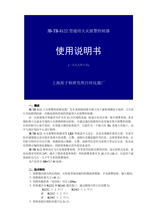
当火灾探测器通过回路总线LED灯点燃,液晶屏显示火警回路(或楼层)、部位(或房号),当有连续多个探测器报警时,显示屏除显示报警首地址外,重复显示后续报警地址和火警总数。按消音键,可切断火灾声响,但一旦控制器接收到新的火警信号时,系统则再次发出火警声响。
JB-TB-8122箱体设计为小容量报警系统,外型采用挂壁式薄型结构,适合挂壁式安装。备电电源采用单组24V,减少了箱体重量和体积,单机报警容量可从16点至126点,以适用于建筑面积为几百~几千平方米的报警场所。
本产品符合GB4717-93标准。
二、技术特性
⒈探测器回路为两总线制,可挂接带地址编码的烟温探测器、手动报警按钮、输入模块;
⒉探测器容量为2×63点;
⒊回路传输距离(双绞线)可达1500m;
⒋控制器具有RS232和RS485通信接口,通过跳线可将它们设置为:
RS232×1个口, RS485×1个口
或RS232×2个口
或RS485×2个口;
⒌系统连接区域机容量可达31台;
⒍采用双绞屏蔽线RS485通信距离可达1200m;
⒎RS232通信距离为17m;
⒊JB-TB-8122电源板
a) P1交流电源。
b) P2 6芯插头,为I/O板提供直流电源。
c) P3 2芯插头,为电池充电电源,红线接电池“+”极,黑线接电池“-”极。
六、运行和操作
⒈开机
拨好机箱地址,检查系统连线,合上电源开关,机器运行,手动联动和交流工作指示灯亮,液晶显示:
接着显示:
按“1”进入校时功能,按“2”进入下一步。
CT14
3C
NO
3号继电器常开触点
COM
3号继电器动触点
NC
网络化系统主机AXT8182使用说明书

1公共广播系列网络广播系统 AXT 8182网络广播中心AXT 8266网络点播终端欢迎惠顾。
您对本产品之选用显示了您的专业眼光。
使用前请认真阅读本说明书.性能特点● 功能非常齐备的公共广播系统。
● 全数字化传输。
以局域网为主要传输媒介,传输距离可达几十公里。
● 可利用现有局域网架设,具有施工快、节省投资的特点,并实现了多网合一。
● 突破传统公共广播只能下传和只能由机房集中控制的格局,具有强大的互动功能。
● 分区和分组可任意组合、随时重组而无须另行布线。
AXT8401ETHERNETAXT1488适宜于商厦、学校(如大学城)、楼群、机场、车站场、地铁站等场合使用的。
目录第一章系统和硬件篇 (4)1.1系统应用案例(以某学校为例) (4)1.1.1 示例系统结构图 (4)1.1.2示例系统特点介绍 (4)1.2网络广播中心系统介绍 (5)1.2.1 前面板 (5)1.2.2 后面板 (5)1.2.3 单机特点 (6)1.3网络广播终端系统介绍 (6)1.3.1 前面板 (6)1.3.2 后面板 (7)1.4最小系统 (7)1.4.1 最小系统结构图 (7)1.4.2 最小系统的主要特点 (7)1.4.3 最小系统的连接 (8)1.5典型系统 (9)1.5.1 典型系统的结构图 (9)1.5.2 典型系统的主要特点 (9)1.5.3 典型系统的连接 (9)第二章操作和设置篇 (10)2.1 系统启运过程 (10)2.2 查看系统工作状态 (11)2.3 对分区进行常用操作 (12)2.3.1 给分区播放节目、节目组 (12)2.3.2 在分区中插入钟声或主机的寻呼 (12)2.3.3 对分区监听或调节分区音量 (13)2.4 对分区进行其它操作 (13)2.4.1手动告警 (13)2.4.2手动控制主机的四路输出电源 (13)2.4.3试听各个节目源 (13)2.4.4给分区播放内置CD (14)2.4.5程控、手动选择 (14)2.4.6广播优先级排列 (14)2.5 综合参数设置 (15)2.6.1定时点操作 (16)2.6.2使用模拟键盘输入文字 (18)2.6.3保存或调用定时方案 (19)2.7.1模拟信号输入接口介绍 (20)2.7.2录音或节目制作 (20)2.7.3节目分类管理 (21)2.8 分区设置 (22)2.8.1 分区定义 (22)22.8.2 分组定义 (23)2.8.3 改变分组与分区的排列顺序 (23)2.9 扩展模块设置 (24)2.9.1 电话设置 (24)2.9.2 告警设置 (24)附录性能规格 (26)3第一章系统和硬件篇1.1系统应用案例(以某学校为例)1.1.1示例系统结构图1.1.2示例系统特点介绍具有本说明书封面所介绍的全部性能特点系统按预先编制的程序运行,可无人值守。
(2021年整理)adc0808中文资料

adc0808中文资料编辑整理:尊敬的读者朋友们:这里是精品文档编辑中心,本文档内容是由我和我的同事精心编辑整理后发布的,发布之前我们对文中内容进行仔细校对,但是难免会有疏漏的地方,但是任然希望(adc0808中文资料)的内容能够给您的工作和学习带来便利。
同时也真诚的希望收到您的建议和反馈,这将是我们进步的源泉,前进的动力。
本文可编辑可修改,如果觉得对您有帮助请收藏以便随时查阅,最后祝您生活愉快业绩进步,以下为adc0808中文资料的全部内容。
11.2。
4 典型的集成ADC芯片为了满足多种需要,目前国内外各半导体器件生产厂家设计并生产出了多种多样的ADC芯片。
仅美国AD公司的ADC产品就有几十个系列、近百种型号之多.从性能上讲,它们有的精度高、速度快,有的则价格低廉.从功能上讲,有的不仅具有A/D转换的基本功能,还包括内部放大器和三态输出锁存器;有的甚至还包括多路开关、采样保持器等,已发展为一个单片的小型数据采集系统。
尽管ADC芯片的品种、型号很多,其内部功能强弱、转换速度快慢、转换精度高低有很大差别,但从用户最关心的外特性看,无论哪种芯片,都必不可少地要包括以下四种基本信号引脚端:模拟信号输入端(单极性或双极性);数字量输出端(并行或串行);转换启动信号输入端;转换结束信号输出端。
除此之外,各种不同型号的芯片可能还会有一些其他各不相同的控制信号端.选用ADC芯片时,除了必须考虑各种技术要求外,通常还需了解芯片以下两方面的特性.(1)数字输出的方式是否有可控三态输出。
有可控三态输出的ADC 芯片允许输出线与微机系统的数据总线直接相连,并在转换结束后利用读数信号RD选通三态门,将转换结果送上总线。
没有可控三态输出(包括内部根本没有输出三态门和虽有三态门、但外部不可控两种情况)的ADC芯片则不允许数据输出线与系统的数据总线直接相连,而必须通过I/O接口与MPU交换信息。
(2)启动转换的控制方式是脉冲控制式还是电平控制式.对脉冲启动转换的ADC芯片,只要在其启动转换引脚上施加一个宽度符合芯片要求的脉冲信号,就能启动转换并自动完成。
8路8工作方式的无线遥控开关使用说明

8路8工作方式的学习型无线遥控开关使用说明书(2007版本)8路8种工作方式选择的无线遥控开关是我公司根据用户要求推出的一款人性化、理想化的实用无线控制装置。
学习功能方便用户更换遥控器,更方便用户软件更换输出端。
多种工作方式选择,更方便用户更换不同的工作方式,用于不同的场合和不同的用途。
本无线遥控开关不但适应本公司的加强型无线遥控发射器,而且兼容市场上的各种固定编码的无线遥控发射器。
不但适用于遥控发射器与接收板一对一操作,而且能够实现多路遥控器的组合控制。
对用户开放6种工作方式,使用户根据自己的需要来选择方式,不但扩大了应用范围,而且对临时更换用途提供了方便,增大了应用灵活性。
电路输出具有常闭、常开两种输出方式也方便了用户不同用途的选择。
6路无线遥控接收板的6路输出,均有状态指示灯指示工作状态,用户对其工作情况直观明了。
该无线遥控开关广泛应用到家庭中,工业控制中,对于学生学习自动化控制,启迪开发思路也是一个良好的教具。
一、8路8工作方式选择的无线遥控开关的控制分布图二、学习与设置:在无线遥控接收板未通电之前按下学习开关,接通电源,状态指示灯点亮,松开学习按键开关,状态指示灯保持点亮。
遥控器控制的顺序如上图所示的继电器顺序。
如果使用单码操作的遥控器,,当按下一个按键后,状态指示灯闪烁一次,表示此时第一路学习完毕,按下第二个按键后,状态指示灯闪烁两下表示第二路学习完毕,顺序学习完8路的遥控器操作,每路的学习均有状态指示灯闪烁对应的次数指示。
8路操作学习对码完毕,状态指示灯快速闪烁数次后,仍然保持点亮状态,此时已经进入工作方式的学习状态。
工作方式有下面功能表所示的8种方式。
用户选择一种方式后,根据方式编号找到前面学习遥控器的顺序所对应的操作按键,再次按下此按键,状态指示灯熄灭,方式学习完毕。
例如:上面使用单按键操作的遥控器来学习,8路控制按键分别适用1、2、3、4、5、6、7、8按键,学习的顺序也按自然数顺序,此时如果选用工作方式6,则按上面的学习顺序6所对应的按键6,再按一下即可。
AV9108-03CS8资料

Integrated CircuitSystems, Inc.AV9108CPU Frequency GeneratorBlock DiagramGeneral DescriptionThe A V9108 offers a tiny footprint solution for generating two simultaneous clocks. One clock, the REFCLK, is a fixed output frequency which is the same as the input reference crystal (or clock). The other clock, CLK1, can vary between 2 and 120MHz, with up to 16 selectable preprogrammed frequencies stored in internal ROM.The ICS9108 is ideal for use in a 3.3V system. It can generate a 66.66 MHz clock at 3.3V . In addition, the ICS9108 provides a symmetrical wave form with a worst case duty cycle of 45/55.The ICS9108 has very tight edge control between the CPU clock and 2XCPU clock outputs, with a worst case skew of 250ps.The device has advanced features which include on-chip loop filters, tristate outputs, and power-down capability. A mini-mum of external components - two decoupling capacitors and an optional ferrite bead - are all that are required for jitter-free operation. Standard versions for computer motherboard appli-cations are the A V9108-03, A V9108-05 and the ICS9108-10.Custom masked versions, with customized frequencies and features, are available in 6-8 weeks for a small NRE fee.Features• Runs up to 80 MHz at 3.3V • 50/50 typical duty cycle at 5V •±250ps absolute jitter• Generates frequencies from 2 to 140 MHz • 2 to 32 MHz input reference frequency • Up to 16 frequencies stored internally• Patented on-chip Phase Locked Loop with VCO for clockgeneration• Provides reference clock and synthesized clock • On-chip loop filter• Low power 0.8µ CMOS technology •8-pin or 14-pin DIP or SOIC packagePin ConfigurationPin Descriptions for AV9108-03, AV9108-05 and AV9108-10AV9108-05/-108-Pin DIP , SOICFS1 1 14 FS0FS2 2 13 REFCLK FS3 3 12 VDD AGND 4 11 CLK1GND 5 10 OE (CLK1)PD 6 9 OE (REFCLK)X1/ICLK 7 8 X2AV9108-03/-1114-Pin DIP, SOICAV9108Actual FrequenciesDecoding Table for AV9108-05, 14.318 inputDecoding Table for AV9108-03, 14.318 inputDecoding Table for AV9108-10, 14.318 inputDecoding Table for AV9108-11 (in MHz)Note: The dash number following ICS9108 must be included when ordering product since it specifies the frequency decoding table being ordered. Decoding options can be created by a simple metal mask change.AV9108Frequency Accuracy and Calculation The accuracy of the frequencies produced by the ICS9108 depends on the input frequency and the desired actual output frequency. The formula for calculating the exact frequency is as follows:AOutput Frequency = Input Frequency ×Bwhere A=2, 3, 4 ... 128, andB=2, 3, 4 ... 32.For example, to calculate the actual output frequency for a video monitor expecting a 44.900 MHz clock and using a 14.318 MHz input clock, the closest A/B ratio is 69/22, which gives an output of 44.906 MHz (within 0.02% of the target frequency). Generally, the ICS9108 can produce frequencies within 0.1% of the desired output.Allowable Input and Output Frequencies The input frequency should be between 2 and 32 MHz and the A/B ratio should not exceed 24. The output should fall in the range of 2-120 MHz.Output EnableThe Output Enable feature tristates the specified output clock pins. This places the selected output pins in a high impedance state to allow for system level diagnostic testing.Power-DownIf equipped, the power-down shuts off the specified PLL or entire chip to save current. A few milliseconds are required to reach full functioning speed from a power-down state.Frequency TransitionsA key ICS9108 feature is the ability to provide glitch-free frequency transitions across its output frequency range. The ICS9108 provides smooth transitions between any of the two groups of eight frequencies (when FS3=0 or FS3=1), so that the device willswitch glitch-free between 4-100 MHz and 2-50 MHz.AV9108Absolute Maximum RatingsAVDD, VDD referenced to GND . . . . . . . . . . . . . . . 7VOperating temperature under bias. . . . . . . . . . . . . . . . 0°C to +70°C Storage temperature . . . . . . . . . . . . . . . . . . . . . . . . . . -65°C to +150°CVoltage on I/O pins referenced to GND. . . . . . . . . . . GND -0.5V to VDD +0.5V Power dissipation . . . . . . . . . . . . . . . . . . . . . . . . . . . . 0.5 WattsStresses above those listed under Absolute Maximum Ratings may cause permanent damage to the device. This is a stress rating only and functional operation of the device at these or any other conditions above those indicated in the operational sections of the specifications is not implied. Exposure to absolute maximum rating conditions for extended periods may affect product reliability.Electrical Characteristics at 5V(Operating V DD = +4.5V to +5.5V; T A =0°C to 70°C unless otherwise stated)Note 1: Parameter is guaranteed by design and characterization. Not 100% tested in production.AV9108Electrical Characteristics at 3.3V(Operating V DD = +3.0V to +3.7V; T A =0°C to 70°C unless otherwise stated)Parameter is guaranteed by design and characterization.AV91088-Pin DIP Package14-Pin DIP PackageOrdering InformationAV9108-XXCN8, ICS9108-XXCN14Example:Lead Count=1, 2 or 3 digitsW=.3” SOIC or .6” DIP; None=Standard Width N=DIP (Plastic)Pattern Number (2 or 3 digit number for parts with ROM code patterns)Device Type (consists of 3 or 4 digit numbers)AV91088-Pin Plastic SOIC14-Pin SOIC PackageOrdering InformationICS9108-XXCS8, IS9108-XXCS14Example:Lead Count=1, 2 or 3 digitsW=.3” SOIC or .6” DIP; None=Standard WidthS=SOICDevice Type (consists of 3 or 4 digit numbers)AV9108。
迅迪电子 XD308H 宽输入电压范围降压型 DC DC 转换器规格书说明书
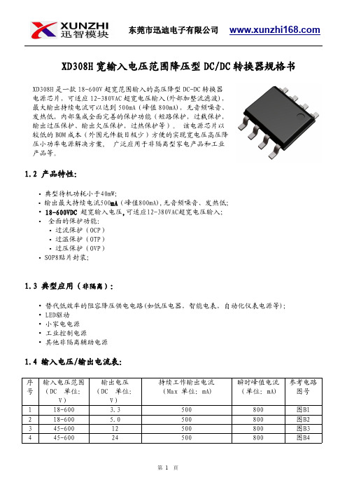
XD308H 宽输入电压范围降压型DC/DC 转换器规格书1.2产品特性:•典型待机功耗小于40mW;•输出最大持续电流500mA (峰值800mA),无音频噪音、发热低;•18-600VDC 超宽输入电压,可适应12-380VAC超宽电压输入;•全面的保护功能:•过流保护(OCP)•过温保护(OTP)•过压保护(OVP)•SOP8贴片封装;1.3典型应用(非隔离):•替代低效率的阻容降压供电电路(如低压电器,智能电表,自动化仪表电源等);•LED驱动•小家电电源•工业控制电源•其他非隔离辅助电源1.4输入电压/输出电流表:序号输入电压范围(DC 单位:V)输出电压(DC 单位:V)持续工作输出电流(Max 单位:mA)瞬时峰值电流(单位:mA)参考电路图号118-600 3.3500800图B1218-600 5.0500800图B2345-60012500800图B3445-60024500800图B4XD308H 是一款18-600V 超宽范围输入的高压降型DC-DC 转换器电源芯片,可适应12-380VAC 超宽电压输入(外部加整流滤波),最大输出持续电流可以达到500mA(峰值800mA),无音频噪音、发热低,内部集成全面完善的保护功能(短路保护,过载保护,输出过压保护、输出欠压保护,过热保护等)。
该电源芯片以较低的BOM 成本(外围元件数目极少)方便的实现宽电压高压降压小功率电源解决方案,广泛应用于非隔离型家电产品和工业产品等。
1.5封装参考:1.6引脚功能:编号名称描述备注1VCC/BP所有控制电路的电源。
外部旁路电容连接点2GND/S芯片参考地。
内部功率MOSFET的源极。
3FB反馈输入4CS电流检测5,6,7,8DRAIN内部功率MOSFET的漏极1.7功能框图:图11.8典型应用电路:1.9绝对最大额定值(备注1):1.10推荐的工作条件(备注2):参数数值单位工作环境温度-40to85°C1.11电气特性:=+25℃。
莫贾8口全光纤无管理交换机产品介绍说明书

EDS-G2008-ELP Series8-port entry-level unmanaged full Gigabit Ethernet switches with plastic housingFeatures and Benefits•Full Gigabit Ethernet ports•Compact size for easy installation•QoS supported to process critical data in heavy traffic•IP40-rated plastic housingCertificationsIntroductionThe EDS-G2008-ELP Series of industrial Ethernet switches have eight Gigabit Ethernet ports and a plastic housing,which are ideal for applications that require simple industrial Ethernet connections.Moreover,to provide greater versatility for use with applications from different industries,the EDS-G2008-ELP Series also allows users to enable or disable the Quality of Service(QoS)function,and broadcast storm protection(BSP)with DIP switches on the outer panel..The EDS-G2008-ELP Series has a12/24/48VDC single power input,DIN-rail mounting,and high-level EMI/EMC capabilities.In addition to its compact size,the EDS-G2008-ELP Series has passed a100%burn-in test to ensure it will function reliably after it has been deployed.The EDS-G2008-ELP Series has a standard operating temperature range of-10to60°C.SpecificationsEthernet Interface10/100/1000BaseT(X)Ports(RJ45connector)8Full/Half duplex modeAuto MDI/MDI-X connectionAuto negotiation speedStandards IEEE802.3for10BaseTIEEE802.3u for100BaseT(X)IEEE802.3ab for1000BaseT(X)IEEE802.3x for flow controlIEEE802.1p for Class of ServiceSwitch PropertiesProcessing Type Store and ForwardMAC Table Size4KPacket Buffer Size 1.5MbitsDIP Switch ConfigurationEthernet Interface Quality of Service(QoS),Broadcast Storm Protection(BSP)Power ParametersConnection1removable3-contact terminal block(s)Input Current0.33A(max.)Input Voltage12/24/48VDCOperating Voltage9.6to60VDCOverload Current Protection SupportedReverse Polarity Protection SupportedPhysical CharacteristicsDimensions36x81x65mm(1.42x3.19x2.56in) Installation DIN-rail mountingWall mounting(with optional kit)Housing PlasticWeight140g(0.31lb)Environmental LimitsAmbient Relative Humidity5to95%(non-condensing)Operating Temperature-10to60°C(14to140°F)Storage Temperature(package included)-40to85°C(-40to185°F)Standards and CertificationsSafety UL61010-2-201EN62368-1(LVD)EMC EN55032/35EN61000-6-2/-6-4EMI CISPR32,FCC Part15B Class AEMS IEC61000-4-2ESD:Contact:6kV;Air:8kVIEC61000-4-3RS:80MHz to1GHz:20V/mIEC61000-4-4EFT:Power:1kV;Signal:1kVIEC61000-4-5Surge:Power:1kV;Signal:1kVIEC61000-4-6CS:10VIEC61000-4-8PFMFShock IEC60068-2-27Vibration IEC60068-2-6Freefall IEC60068-2-32MTBFTime3,404,784hrsStandards Telcordia(Bellcore),GBWarrantyWarranty Period5yearsDetails See /warrantyPackage ContentsDevice1x EDS-G2008-ELP Series switch Documentation1x quick installation guide1x warranty cardDimensionsOrdering InformationModel Name 10/100/1000BaseT(X)Ports(RJ45Connector)Housing Operating Temp.EDS-G2008-ELP8Plastic-10to60°C Accessories(sold separately)Power SuppliesDR-452445W/2A DIN-rail24VDC power supply with universal85to264VAC or120to370VDC input,-10to50°C operating temperatureDR-75-2475W/3.2A DIN-rail24VDC power supply with universal85to264VAC or120to370VDC input,-10to60°C operating temperatureDR-120-24120W/2.5A DIN-rail24VDC power supply with universal88to132VAC or176to264VAC input byswitch,or248to370VDC input,-10to60°C operating temperatureMDR-40-24DIN-rail24VDC power supply with40W/1.7A,85to264VAC,or120to370VDC input,-20to70°Coperating temperatureMDR-60-24DIN-rail24VDC power supply with60W/2.5A,85to264VAC,or120to370VDC input,-20to70°Coperating temperatureWall-Mounting KitsWK-18Wall-mounting kit,1plate(18x120x8.5mm)Rack-Mounting KitsRK-4U19-inch rack-mounting kit©Moxa Inc.All rights reserved.Updated Feb01,2023.This document and any portion thereof may not be reproduced or used in any manner whatsoever without the express written permission of Moxa Inc.Product specifications subject to change without notice.Visit our website for the most up-to-date product information.。
SGL8022W 规格说明书Ver1.6
规格说明书SGL8022W单通道直流LED灯光控制触摸芯片版本V1.6希格玛保留不预先通知而修改此文件的权利。
目录1.概述 (3)2.特性 (3)3.封装及引脚说明 (5)4.封装尺寸图 (6)5.应用电路图 (7)6.电气参数 (8)7.BOM表 (9)1. 概述SGL8022W是一款用于LED灯光亮度调节及开关控制的单通道触摸芯片。
使用该芯片可以实现LED灯光的触摸开关控制和亮度调节。
具有如下功能特点和优势:¾灯光亮度可根据需要随意调节,选择范围宽,操作简单方便。
¾可在有介质(如玻璃、亚克力、塑料、陶瓷等)隔离保护的情况下实现触摸功能,安全性高。
¾应用电压范围宽,可在2.4~5.5V之间任意选择。
¾应用电路简单,外围器件少,加工方便,成本低。
¾抗电源干扰及手机干扰特性好。
EFT可以达到±2KV以上;近距离、多角度手机干扰情况下,触摸响应灵敏度及可靠性不受影响。
2. 特性TI触摸输入对应SO灯光控制输出。
共有四种功能可选,由OPT1和OPT2管脚上电前的输入状态来决定。
具体如下:1)OPT1=1,OPT2=1 对应:不带亮度记忆突明突暗的LED触摸无级调光功能2)OPT1=0,OPT2=1 对应:不带亮度记忆渐明渐暗的LED触摸无级调光功能3)OPT1=1,OPT2=0 对应:带亮度记忆渐明渐暗的LED触摸无级调光功能4)OPT1=0,OPT2=0 对应:LED三段触摸调光功能不带亮度记忆突明突暗的LED触摸无级调光功能如下:¾初始上电时,灯为关灭状态。
¾点击触摸(触摸持续时间小于550ms)时,可实现灯光的亮灭控制。
一次点击触摸,灯亮;再一次点击触摸,灯灭。
如此循环。
灯光点亮或关灭时,无亮度缓冲。
且灯光点亮的初始亮度固定为全亮度的90%。
¾长按触摸(触摸持续时间大于550ms)时,可实现灯光无级亮度调节。
XM-E28 DATASHEET-CN

LED驱动控制/键盘扫描专用集成电路XM-E281.概述XM-E28是一种带键盘扫描电路接口的LED驱动控制专用电路。
内部集成有MCU输入输出控制数字接口、数据锁存器、LED驱动、键盘扫描、辉度调节等电路。
本芯片性能稳定、质量可靠、抗干扰能力强,可适应于24小时长期连续工作的应用场合。
可兼容TM1628,CS1628,SM1628,AIP1628,FD628等芯片2.特性说明●显示模式:4位*13段或7位*10段●8级辉度控制●5V的条件下,位驱动电流可达到650mA●键盘扫描:10×2 (支持组合键)●串行接口(CLK,STB,DAT)●内置时钟振荡电路●内置上电复位电路●工作电压:3.3V~5V●采用COMS工艺●ESD HBM: >8KV(美标883模式)●SOP28封装3.管脚定义4. 管脚功能说明5. 主要电气参数极限参数(Ta = 25℃)电气特性(测试条件:Ta = 25℃,VCC =5V )时序特性(测试条件:Ta = 25℃,VCC =5V)*注:DIN和DOUT为芯片内部PAD位,通过封装合并成DI/O。
6.封装尺寸6.1.S OP28封装:7.典型应用电路7.1.D VD 面板7.2.驱动共阳数码管7.3.使用注意事项1.无用的KI接地,增加抗干扰2.推荐客户推挽输出,高阻输入,这样高速通信的波形会更好3.高速通信的时候去除通信口上的电容,减小通信口的上拉电阻4.建议通信速度100K以下5.强干扰环境下通信频率不宜过高,建议软件加入刷新功能6.驱动共阳数码管需要工作在7位模式7.4.电磁炉面板应用说明8.1.显示功能寄存器地址和显示模式该寄存器存储通过串行接口从外部器件传送到XM-E28的数据,地址分配如下:8.2. 键扫描和按键扫描数据寄存器按键扫描矩阵为10X2bit ,如下图所示:按键数据存储地址如下表所示,用读指令读取,从最低位开始读取:8.3. 指令说明指令用来设置显示模式和LED 驱动器的状态。
- 1、下载文档前请自行甄别文档内容的完整性,平台不提供额外的编辑、内容补充、找答案等附加服务。
- 2、"仅部分预览"的文档,不可在线预览部分如存在完整性等问题,可反馈申请退款(可完整预览的文档不适用该条件!)。
- 3、如文档侵犯您的权益,请联系客服反馈,我们会尽快为您处理(人工客服工作时间:9:00-18:30)。
CS8182Micropower 200 mALow Dropout Tracking Regulator/Line DriverThe CS8182 is a monolithic integrated low dropout tracking regulator designed to provide adjustable buffered output voltage that closely tracks (±10 mV) the reference input. The output delivers up to 200 mA while being able to be configured higher, lower or equal to the reference voltages.The output has been designed to operate over a wide range (2.8 V to45 V) while still maintaining excellent DC characteristics. The CS8182 is protected from reverse battery, short circuit and thermal runaway conditions. The device also can withstand 45 V load dump transients and −50 V reverse polarity input voltage transients. This makes it suitable for use in automotive environments.The V REF/ENABLE lead serves two purposes. It is used to provide the input voltage as a reference for the output and it also can be pulled low to place the device in sleep mode where it nominally draws less than 30 m A from the supply.Features•200 mA Source Capability•Output Tracks within ±10 mV Worst Case•Low Dropout (0.35 V Typ. @ 200 mA)•Low Quiescent Current•Thermal Shutdown•Short Circuit Protection•Wide Operating Range•Internally Fused Leads in SO−8 Package•For Automotive and Other Applications Requiring Site and Change ControlV OUTAdjV REF/ENABLEGNDV INFigure 1. Block DiagramDevice Package Shipping†ORDERING INFORMATION*CS8182YDF8SO−895 Units/Rail CS8182YDFR8SO−8CS8182YDPS5D2PAK 5−PIN2500 Tape & ReelCS8182YDPSR5*Consult your local sales representative for SO−8 with exposed pads package option.D2PAK 5−PIN750 Tape & Reel50 Units/Rail†For information on tape and reel specifications, including part orientation and tape sizes, please refer to our T ape and Reel Packaging Specifications Brochure, BRD8011/D.PACKAGE PIN DESCRIPTIONMAXIMUM RATINGSvalues (not normal operating conditions) and are not valid simultaneously. If these limits are exceeded, device functional operation is not implied, damage may occur and reliability may be affected.1.60 second maximum above 183°C.2.−5°C/+0°C allowable conditions.*Depending on thermal properties of substrate. R q JA = R q JC + R q CAELECTRICAL CHARACTERISTICS (V IN = 14 V; V REF/ENABLE > 2.75 V; −40°C < T J < +125°C; C OUT≥ 10 m F;0.1 W< C < 1.0 W @ 10 kHz, unless otherwise specified.)Regular OutputV/ENABLEOUTTYPICAL CHARACTERISTICS181614121086420Figure 2. Quiescent Current vs. Output Current20406080100120140160180200OUTPUT CURRENT (mA)Q U I E S C E N T C U R R E N T (m A )Figure 3. Quiescent Current vs. Input Voltage(Operating Mode)10.90.80.70.60.50.30.20.10051015202530354045V IN , INPUT VOLTAGE (V)Q U I E S C E N T C U R R E N T (m A )0.4Figure 4. Quiescent Current vs. Input Voltage(Sleep Mode)Figure 5. V OUT Reverse Current Figure 6. V OUT Reverse Current51015202530354045V IN , INPUT VOLTAGE (V)Q U I E S C E N T C U R R E N T(m A )510152025FORCED V OUT VOLTAGE (V)C U R R E N T I N T O V O U T (m A )510152025FORCED V OUT VOLTAGE (V)C U R R E N T I N T O V O U T (m A )303540CIRCUIT DESCRIPTIONENABLE FunctionBy pulling the V REF /ENABLE lead below 2.0 V typically,(see Figure 10 or Figure 11), the IC is disabled and enters a sleep state where the device draws less than 55 m A from supply. When the V REF /ENABLE lead is greater than 2.75 V ,V OUT tracks the V REF /ENABLE lead normally.Output VoltageThe output is capable of supplying 200 mA to the load while configured as a similar (Figure 7), lower (Figure 9), or higher (Figure 8) voltage as the reference lead. The Adj lead acts as the inverting terminal of the op amp and the V REF lead as the non−inverting.The device can also be configured as a high−side driver as displayed in Figure 12.Figure 7. Tracking Regulator at the Same VoltageLoads 5.0 VB+V OUT +V REFFigure 8. Tracking Regulator at Higher VoltagesLoads V REFB+Figure 9. Tracking Regulator at Lower VoltagesLoadsV REFB+V OUT +V REF (R2R1)R2)Figure 10. Tracking Regulator with ENABLE CircuitV REFB+Figure 11. Alternative ENABLE CircuitFigure 12. High−Side DriverMCUB+V OUT +B )*V SAT** C2 is required for stability.* C1 is required if the regulator is far from the power source filter.5.0 V 6.0 V−40 V To Load *** C3 is recommended for EMC susceptibility.APPLICATION NOTESV OUT Short to BatteryThe CS8182 will survive a short to battery when hooked up the conventional way as shown in Figure 13. No damage to the part will occur. The part also endures a short to battery when powered by an isolated supply at a lower voltage as inFigure 14. In this case the CS8182 supply input voltage is set at 7 V when a short to battery (14 V typical) occurs on V OUT which normally runs at 5 V . The current into the device (ammeter in Figure 14) will draw additional current as displayed in Figure 15.Automotive Battery typically 14 VFigure 13.Figure 14.LoadsAutomotive Battery typically 14 V** C2 is required for stability.Figure 15. VOUT Short to Battery2.01.81.61.41.21.00.60.40.26510152025V OUT VOLTAGE (V)C U R R E N T (m A )0.878911121314161718192122232426Switched ApplicationThe CS8182 has been designed for use in systems where the reference voltage on the V REF /ENABLE pin is continuously on. Typically, the current into the V REF /ENABLE pin will be less than 1.0 m A when the voltage on the V IN pin (usually the ignition line) has been switched out (V IN can be at high impedance or at ground.)Reference Figure 16.BATIgnition Figure 16.External CapacitorsThe output capacitor for the CS8182 is required for stability. Without it, the regulator output will oscillate. Actual size and type may vary depending upon the application load and temperature range. Capacitor effective series resistance (ESR) is also a factor in the IC stability. Worst−case is determined at the minimum ambient temperature and maximum load expected.The output capacitor can be increased in size to any desired value above the minimum. One possible purpose of this would be to maintain the output voltage during brief conditions of negative input transients that might be characteristic of a particular system.The capacitor must also be rated at all ambient temperatures expected in the system. To maintain regulator stability down to −40°C, a capacitor rated at that temperature must be used.More information on capacitor selection for SMART REGULA TOR®s is available in the SMART REGULA TOR application note, “Compensation for Linear Regulators,”document number SR003AN/D, available through our website at .Calculating Power Dissipation in a Single Output Linear RegulatorThe maximum power dissipation for a single output regulator (Figure 17) is:PD(max)+{V IN(max)*V OUT(min)}I OUT(max))V IN(max)I Q(1) where:V IN(max) is the maximum input voltage,V OUT(min) is the minimum output voltage,I OUT(max) is the maximum output current, for the application,andI Q is the quiescent current the regulator consumes at I OUT(max).Once the value of PD(max) is known, the maximum permissible value of R q JA can be calculated:R q JA+150°C*T AP D(2)The value of R q JA can then be compared with those in the package section of the data sheet. Those packages with R q JA’s less than the calculated value in equation 2 will keep the die temperature below 150°C.In some cases, none of the packages will be sufficient to dissipate the heat generated by the IC, and an external heat sink will be required.Figure 17. Single Output Regulator with KeyPerformance Parameters LabeledVHeatsinksA heatsink effectively increases the surface area of the package to improve the flow of heat away from the IC and into the surrounding air.Each material in the heat flow path between the IC and the outside environment will have a thermal resistance. Like series electrical resistances, these resistances are summed to determine the value of R q JA:R q JA+R q JC)R q CS)R q SA(3) where:R q JC = the junction−to−case thermal resistance,R q CS = the case−to−heatsink thermal resistance, andR q SA = the heatsink−to−ambient thermal resistance.R q JC appears in the package section of the data sheet. Like R q JA, it is a function of package type. R q CS and R q SA are functions of the package type, heatsink and the interface between them. These values appear in heat sink data sheets of heatsink manufacturers.SOIC−8 DF SUFFIX CASE 751−07 ISSUE ABNOTES:1.DIMENSIONING AND TOLERANCING PER ANSIY14.5M, 1982.2.CONTROLLING DIMENSION: MILLIMETER.3.DIMENSION A AND B DO NOT INCLUDE MOLDPROTRUSION.4.MAXIMUM MOLD PROTRUSION 0.15 (0.006) PERSIDE.5.DIMENSION D DOES NOT INCLUDE DAMBARPROTRUSION. ALLOWABLE DAMBARPROTRUSION SHALL BE 0.127 (0.005) TOTAL INEXCESS OF THE D DIMENSION AT MAXIMUMMATERIAL CONDITION.6.751−01 THRU 751−06 ARE OBSOLETE. NEWSTANDARD IS 751−07.DIMAMIN MAX MIN MAXINCHES4.805.000.1890.197MILLIMETERSB 3.80 4.000.1500.157C 1.35 1.750.0530.069D0.330.510.0130.020G 1.27 BSC0.050 BSCH0.100.250.0040.010J0.190.250.0070.010K0.40 1.270.0160.050M0 8 0 8N0.250.500.0100.020S 5.80 6.200.2280.244 YM0.25 (0.010)Z S X S____Figure 18. SOIC−8ǒmminchesǓSCALE 6:1SOLDERING FOOTPRINTD 2PAK−5DP SUFFIX CASE 936AC−01ISSUE ODIM MIN MAX MIN MAX MILLIMETERS INCHES A 0.3960.40610.0510.31B 0.3300.3408.388.64C 0.1700.180 4.31 4.57D 0.0260.0360.660.91E 0.0450.0551.14 1.40G 0.067 REF 1.70 REF H 0.5800.62014.7315.75K 0.0550.066 1.40 1.68L 0.0000.0100.000.25M 0.0980.1082.49 2.74N 0.0170.0230.430.58NOTES:1.DIMENSIONS AND TOLERANCING PER ANSI Y14.5M, 1982.2.CONTROLLING DIMENSION: INCH.3.PACKAGE OUTLINE EXCLUSIVE OF MOLD FLASH AND METAL BURR.4.PACKAGE OUTLINE INCLUSIVE OF PLATING THICKNESS.5.FOOT LENGTH MEASURED ATINTERCEPT POINT BETWEEN DATUM A AND LEAD SURFACE.P 0.0900.110 2.29 2.79R 0 8 S 0.0950.105 2.41 2.67U 0.30 REF 7.62 REF V 0.305 REF 7.75 REF W0.0100.25__0 8 __SMART REGULATOR is a registered trademark of Semiconductor Components Industries, LLC (SCILLC).ON Semiconductor and are registered trademarks of Semiconductor Components Industries, LLC (SCILLC). SCILLC reserves the right to make changes without further notice to any products herein. SCILLC makes no warranty, representation or guarantee regarding the suitability of its products for any particular purpose, nor does SCILLC assume any liability arising out of the application or use of any product or circuit, and specifically disclaims any and all liability, including without limitation special, consequential or incidental damages.“Typical” parameters which may be provided in SCILLC data sheets and/or specifications can and do vary in different applications and actual performance may vary over time. All operating parameters, including “Typicals” must be validated for each customer application by customer’s technical experts. SCILLC does not convey any license under its patent rights nor the rights of others. SCILLC products are not designed, intended, or authorized for use as components in systems intended for surgical implant into the body, or other applications intended to support or sustain life, or for any other application in which the failure of the SCILLC product could create a situation where personal injury or death may occur. Should Buyer purchase or use SCILLC products for any such unintended or unauthorized application, Buyer shall indemnify and hold SCILLC and its officers, employees, subsidiaries, affiliates, and distributors harmless against all claims, costs, damages, and expenses, and reasonable attorney fees arising out of, directly or indirectly, any claim of personal injury or death associated with such unintended or unauthorized use, even if such claim alleges that SCILLC was negligent regarding the design or manufacture of the part. SCILLC is an Equal Opportunity/Affirmative Action Employer. This literature is subject to all applicable copyright laws and is not for resale in any manner.PUBLICATION ORDERING INFORMATION。
