PAS-DAS软件安装使用说明
ICP DAS PISO-813 Series Classic Driver DLL软件手册说明书
T ABLE OF C ONTENTS1.INTRODUCTION (2)1.1O BTAINING THE D RIVER I NSTALLER P ACKAGE (3)1.2D RIVER I NSTALLING P ROCEDURE (4)1.3P N P D RIVER I NSTALLATION (6)2.DLL FUNCTION DESCRIPTIONS (8)2.1E RROR C ODE T ABLE (10)2.2A/D G AIN C ODE T ABLE (11)2.3T EST F UNCTIONS (12)PISO813_GetDllVersion (12)PISO813_ShortSub (12)PISO813_FloatSub (13)2.4D RIVER F UNCTIONS (14)PISO813_GetDriverVersion (14)PISO813_DriverInit (14)PISO813_DriverClose (15)PISO813_GetConfigAddressSpace (15)2.5D IGITAL I NPUT/O UTPUT F UNCTIONS (17)PISO813_OutputByte (17)PISO813_InputByte (17)PISO813_OutputWord (18)PISO813_InputWord (18)2.6A NALOG I NPUT F UNCTIONS (19)PISO813_SetChGain (19)PISO813_AD2F (20)PISO813_AD_Hex (21)PISO813_AD_Float (22)PISO813_Ads_Hex (23)PISO813_Ads_Float (24)3.DEMO PROGRAMS (25)3.1F OR M ICROSOFT W INDOWS (25)3.2F OR DOS (28)4.PROGRAMS ARCHITECTURE (29)5.PROBLEMS REPORT (30)1.IntroductionThe software is a collection of digital I/O, analog input subroutines for PISO-813 series card add-on cards for Windows 95/98/NT/2000 and 32-bit Windows XP/2003/Vista/7 applications. The application structure is presented in the following diagram.The subroutines in PISO813.DLL are easy understanding as its name standing for. It provides powerful, easy-to-use subroutine for developing your data acquisition application. Your program can call these DLL functions by VB, VC, Delphi, BCB, 2005 and C#.NET 2005 easily. To speed-up your developing process, some demonstration source program are provided.1.1Obtaining the Driver Installer PackagePIO-821 series card can be used on Linux and Windows 95/98/NT/2000 and 32-bit XP/2003/Vista/7 based systems, and the drivers are fully Plug and Play (PnP) compliant for easy installation.The driver installer package for the PISO-813 series can be found on the supplied CD-ROM, or can be obtained from the ICP DAS FTP web site. The location and addresses are indicated in the table below:CD:\\ NAPDOS\PCI\PISO-813\DLL_OCX\ftp:///pub/cd/iocard/pci/napdos/pci/piso-813/dll_ocx//pub/cd/iocard/pci/napdos/pci/piso-813/dll_ocx/Install the appropriate driver for your operating system, as follows:Name OSWin2K_XP_7 For Windows 2000 and 32- bit Windows XP/Vista/7Win98 For Windows 95/98/MEWinNT For Windows NT 4.01.2Driver Installing ProcedureBefore the driver installation, you must complete the hardware installation. For detailed information about the hardware installation, please refer to hardware user manual of PISO-813 series card.The hardware user manual is contained in:CD:\NAPDOS\PCI\PISO-813 \Manual\To install the PISO-813 series classic drivers, follow the procedure described below:1.3PnP Driver InstallationNote: Some operating system (such as Windows Vista/7) will find the new card and make it work automatically, so the Step2 to Step4 will be skipped.2.DLL Function DescriptionsAll of the functions provided for PISO-813 series card are listed below in Tables 2-1 to 2-4. This list of functions is expanded on in the text that follows. However, in order to make a clear and simplified description of the functions, the attributes of the input and output parameters for every function is indicated as [input] and [output] respectively, as shown in following table. Furthermore, the error code of all functions supported by PISO-813 is also listed in Section 2-1.Keyword Parameter must be set by the user beforecalling the function Data/value from this parameter is retrieved after calling the function[Input] Yes No [Output] No Yes[Input, Output] Yes YesTable2-2: Driver Functions Table of PISO813.DLLSection Function Definition2.4 Driver FunctionsWORD PISO813_DriverInit(void);viod PISO813_DriverClose(void);WORD PISO813_SearchCard(WORD *wBoards, DWORD dwPIOCardID);WORD PISO813_GetDriverVersion(WORD *wDriverVersion);WORD PISO813_GetConfigAddressSpace (WORD wBoardNo, DWORD*wAddrBase, WORD *wIrqNo, WORD *wSubVendor, WORD*wSubDevice, WORD *wSubAux, WORD *wSlotBus, WORd*wSlotDevice);Table2-3: DIO Functions Table of PISO813.DLLSection Function Definition2.5 Digital Input/Output Functionsvoid PISO813_OutputWord(DWORD wPortAddress, DWORD wOoutData);void PISO813_OutputByte(DWORD wPortAddr, WORD bOutputValue);DWORD PISO813_InputWord(DWORD wPortAddress);WORD PISO813_InputByte(DWORD wPortAddr);Table2-4: A/D Functions Table of PISO813.DLLSection Function Definition2.6 Analog Input FunctionsWORD PISO813_SetChGain(DWORD wAddrBase, WORD wChannel, WORDwGainCode);WORD PISO813_AD_Hex(DWORD wAddrBase,);WORD PISO813_Ads_Hex(DWORD wAddrBase, WORD *wBuffer, DWORDdwDataNo);float PISO813_AD_Float(DWORD wAddrBase, WORD wJump20v, WORDwBipolar);float PISO813_Ads_Float (DWORD wAddrBase, WORD wJump20v, WORDwBipolar, float *fBuffer, DWORD dwDataNo);float PISO813_AD2F(WORD whex, WORD wGainCode, WORD wJump20v,WORD wBipolar);2.1Error Code TableFor the most errors, it is recommended to check:1.Does the device driver installs successful?2.Does the card have plugged?3.Does the card conflicts with other device?4.Close other applications to free the system resources.5.Try to use another slot to plug the card.6.Restart your system to try again.Error Code Error ID Error String0 PISO813_NoError OK (No Error)1 PISO813_DriverOpenError Device driver can’t be opened2 PISO813_DriverNoOpen The PISO813_DriverInit() function must be called first3 PISO813_GetDriverVersionError Get driver version error4 PISO813_CallDriverError Call driver is error5 PISO813_FindBoardError Cannot find board6 PISO813_ExceedBoardNumber The board number exceeds the maximum board number (7).0xffff PISO813_TimeOutError Delay time out-100.0 PISO813_ADError2 A/D converter error2.2A/D Gain Code TableJP2: Bipolar Mode GAIN Control Code TableGAINInput RangeGAIN2 GAIN1 GAIN0 Gain Code JP1: 10 V JP1: 20 V1 ±5 V ±10 V 0 0 0 0x02 ±2.5 V ±5 V 0 0 1 0x1 4 ±1.25 V ±2.5 V 0 1 0 0x2 8 ±0.625 V ±1.25 V 0 1 1 0x3 16 Not Use ±0.625 V 1 0 0 0x4JP2: Unipolar Mode GAIN Control Code TableGAINInput RangeGAIN2 GAIN1 GAIN0 Gain Code JP1: 10 V JP1: 20 V1 0 ~ 10 V Not Use 0 0 0 02 0 ~ 5 V Not Use 0 0 1 1 4 0 ~ 2.5 V Not Use 0 1 0 2 8 0 ~ 1.25 V Not Use 0 1 13 16 0 ~ 0.625 V Not Use 1 0 0 42.3Test FunctionsPISO813_GetDllVersionTo get the version number of PISO813.DLL.Syntax:WORD PISO813_GetDllVersion(void);Parameters:NoneReturns:DLL version information.For example: If 200(hex) value is return, it means driver version is 2.00.PISO813_ShortSubTo perform the subtraction as nA - nB in short data type. This function is provided for testing DLL linkage purpose.PISO813_FloatSubTo perform the subtraction as fA - fB in float data type. This function is provided for testing DLL linkage purpose.2.4Driver FunctionsPISO813_GetDriverVersionThis subroutine will read the version number of PISO-813 driver.Syntax:WORD PISO813_GetDriverVersion(WORD *wDriverVersion);Parameters:wDriverVersion[Output] address of wDriverVersionReturns:PISO813_NoError OKPISO813_DriverNoOpen The PISO-813 driver no openPIDO813_GetDriverVersionError Read driver version errorPISO813_DriverInitThis subroutine will open the PISO-813 driver and allocate the resource for the device. This function must be called once before calling other PISO-813 functions.Syntax:WORD PISO813_DriverInit();Parameters:NoneReturns:PISO813_NoError OKPISO813_DriverNoOpen Open PISO-813 driver errorPISO813_DriverCloseW This subroutine will close the PISO-813 Driver and release the resource from the device. This function must be called once before exit the user's application.Syntax:void PISO813_DriverClose();Parameters:NoneReturns:NonePISO813_GetConfigAddressSpaceGet the I/O address of PISO-813 board n.Syntax:WORD PISO813_GetConfigAddressSpace (WORD wBoardNo,DWORD *wAddrBase,WORD *wIrqNo,WORD *wSubVendor,WORD *wSubDevice,WORD *wSubAux,WORD *wSlotBus,WORd *wSlotDevice);Parameters:wBoardNo[Input] PISO-813 board number.2.5Digital Input/Output FunctionsPISO813_OutputByteThis subroutine will send the 8 bits data to the desired I/O port.PISO813_InputByteThis subroutine will input the 8 bit data from the desired I/O port.Syntax:WORD PISO813_InputByte(DWORD wPortAddr);Parameters:wPortAddr[Input] I/O port addresses, please refer to function PISO813_GetConfigAddressSpace().Only the low WORD is valid.Returns:16 bits data with the leading 8 bits are all 0. (Only the low BYTE is valid.)PISO813_OutputWordThis subroutine will send the 16 bits data to the desired I/O port.PISO813_InputWordThis subroutine will input the 16 bit data from the desired I/O port.Syntax:WORD PISO813_InputWord(DWORD wPortAddr);Parameters:wPortAddr[Input] I/O port addresses, please refer to function PISO813_GetConfigAddressSpace().Only the low WORD is valid.Returns:16 bits data. Only the low WORD is valid.2.6Analog Input FunctionsPISO813_SetChGainThis subroutine wills setting the cannel number and Gain Code (Refer to Section 2.2) for the AD converter.PISO813_AD2FThis subroutine will convert the Hex value to floating value depending on Gain Code , Bipolar/Unipolar and 10 V/20 V.PISO813_AD_HexThis subroutine will perform an A/D conversion by polling. The A/D converter is 12 bits for PISO-813. Refer to PISO813_SetChGain().Syntax:WORD PISO813_AD_Hex(DWORD wBase);Parameters:wBase[Input] I/O port base addresses, please refer to PISO813_GetConfigAddressSpace().Returns:PISO813_TimeOutError A/D converter error (return 0xffff)Other value The Hex value of A/D conversion (0 to 0x0ffff)PISO813_AD_FloatThis subroutine will perform an A/D conversion by polling. The A/D converter is 12 bits for PISO-813. This subroutine will compute the result according to the configuration code (Section 2.2). Refer to PISO813_SetChGain().PISO813_Ads_HexThis subroutine will perform a number of A/D conversions by polling. This subroutine is very similar to PISO813_AD_Hex except that this subroutine will perform wCount of conversions instead of just one conversion. After A/D conversing, the A/D data are stored in a buffer in Hex format. The wBuf is the starting address of this data buffer. Refer to PISO813_SetChGain().PISO813_Ads_FloatThis subroutine will perform a number of A/D conversions by polling. This subroutine is very similar to PISO813_AD_Float except that this subroutine will perform wCount of conversions instead of just one conversion. Then the A/D data are stored in a data buffer in Float format. The fBuf is the starting address of this data buffer. Refer to PISO813_SetChGain().The list of demo programs:Config Demo: Get cards informationAD Float Demo: Get the AD floating value AD Hex Demo: Get the AD Hex valueBCB4 → for Borland C ++ Builder 4PISO813.H → Header files PISO813.LIB → Linkage library for BCB onlyDelphi4 → for Delphi 4PISO813.PAS → Declaration filesVC6 → for Visual C ++ 6 PISO813.H → Header files PISO813.LIB → Linkage library for VC onlyVB6 → for Visual Basic 6PISO813.BAS → Declaration files2005 → for 2005PISO813.vb →Visual Basic Source filesCSharp2005 → for C#.NET2005 PISO813.cs → Visual C# Source files3. Demo Programs3.1 For Microsoft WindowsICP DAS PISO-813 Series Classic Driver DLL contains a set of functions. It can be used in various application programs for PISO-813 series card. The API functions supports many development environments and programming languages, including Microsoft Visual C++,Visual Basic ,Borland Delphi ,Borland C Builder++,Microsoft Visual C#.NET ,Microsoft Visual .The demo programs of Windows OS for the PISO-813 series can be found on the supplied CD-ROM, or can be obtained from the ICP DAS FTP web site. The location and addresses are indicated in the table below: CD:\NAPDOS\PCI\PISO-813\DLL_OCX\Demo\Config Demo: Get cards informationFollowing figure is the result for the demo program. It can be applied to obtain the hardware information and function test of the PISO-813 board.AD Float Demo: Get the AD floating valueThis demo program provides the get the AD floating value.AD Hex Demo: Get the AD Hex value This demo program provides the get the AD Hex value.\TC\*.* → for Turbo C 2.xx or above \MSC\*.* → for MSC 5.xx or above\BC\*.* →for BC 3.xx or aboveThe list of demo programs:Dome1:Measure 32-channel A/I. Bipolar range: -10 V to +10VNote that all of the hardware control functions need to be provided and processed by user themselves.\TC\LIB\*.*→ for TC Library\TC\DEMO\*.* → for TC demo program \TC\DIAG\*.* → for TC diagnostic program\TC\LIB\Large\*.* → TC Large Model Library \TC\LIB\Huge\*.*→ TC Huge Model Library File \TC\LIB\Large\PIO.H → TC Declaration File\TC\LIB\Large\TCPIO_L.LIB → TC Large Model Library File \TC\LIB\Huge\PIO.H → TC Declaration File\TC\LIB\Huge\TCPIO_H.LIB → TC Huge Model Library File \MSC\LIB\Large\PIO.H → MSC Declaration File\MSC\LIB\Large\MSCPIO_L.LIB → MSC Large Model Library File \MSC\LIB\Huge\PIO.H → MSC Declaration File\MSC\LIB\Huge\MSCPIO_H.LIB → MSC Huge Model Library File \BC\LIB\Large\PIO.H → BC Declaration File\BC\LIB\Large\BCPIO_L.LIB → BC Large Model Library File \BC\LIB\Huge\PIO.H → BC Declaration File\BC\LIB\Huge\BCPIO_H.LIB → BC Huge Model Library File3.2 For DOSThe demo program is contained in: CD:\NAPDOS\PCI\PISO-813\DOS\PISO813\4. Programs ArchitectureHardware DevicesUser ’s Application.VXDs 、.SYSs (Device Driver)DLLsFunction Call into DLLsServices Call into Kernel-ModeDevice ControlDevelopment Toolkit5.Problems ReportTechnical support is available at no charge as described below. The best way to report problems is to send electronic mail to****************** or ************************ on the Internet.When reporting problems, please include the following information:1.Is the problem reproducible? If so, how?2.What kind and version of platform that you using? For example, Windows 98, Windows 2000 or32-bit Windows XP/2003/Vista/2008/7.3.What kinds of our products that you using? Please see the product’s manual.4.If a dialog box with an error message was displayed, please include the full test of the dialog box,including the text in the title bar.5.If the problem involves other programs or hardware devices, what devices or version of thefailing programs that you using?6.Other comments relative to this problem or any suggestions will be welcomed.After we had received your comments, we will take about two business days to test the problems that you said. And then reply as soon as possible to you. Please check that if we had received you comments? And please keeps contact with us.。
密码修改说明

一、在线监测软件有两级密码。
操作员密码为1111。
管理员密码为1211。
修改密码方法如下:
1.点击电脑左下角开始-所有程序-PAS-DAS-开发系统。
2.点击开发系统左侧扩展应用-用户管理-定义管理员/操作用户。
3.选择需要修改的用户双击-修改-输入密码。
4.在登陆/注销口令里输入新密码,在核实口令里输入新密码-确定。
二、U23分析仪有两级密码。
1级密码为111。
2级密码为222。
修改分析仪密码方法如下:
1.分析仪面板在测量模式时,按ENTER键进入菜单面板。
2.选择configuration,输入密码222。
3.在弹出界面分别选择 special Functions-codes/Language,进入此菜单后即可修
改密码。
SCS-900-1烟气监测系统操作维护手册

SCS-900-1烟气连续监测系统操作维护手册北京雪迪龙自动控制控制系统有限公司目录1.系统描述2.烟气分析系统3.气体预处理系统测量/校准4.操作规程5.维护5.1取样探头5.2采样管线5.3冷凝器5.4过滤器5.5取样泵5.6 ULTRAMAT23气体分析器5.7 D-R216测尘仪5.8变送器5.9 DAS数据采集处理系统6.熔断器操作表7.备件表1.系统描述1.1总体说明本系统用于烟气排放连续监测,适用于电厂,钢厂等行业。
系统组成见系统图。
监测参数如下:烟气:SO2、NO x、O2、粉尘浓度、流量、温度、压力(监测点位于入烟囱前的烟道上)。
测量参数(SO2,O2)同时可以为为脱硫系统(FGD)提供工艺控制参数及计算脱硫效率。
烟气监测(SO2、NOx、O2、粉尘浓度、流量、温度、压力)参数用于环保排放监测,其中气体组分(SO2、NOx、O2)采用一拖一方式。
即在入烟囱前的烟道上安装气体采样探头和采样管线,输送至分析机柜进行检测分析。
烟气其它参数(粉尘、流量、温度、压力)监测安装在烟道上直接测量,测量输出传到分析室电控柜进行数据采集。
烟气监测参数经过信号处理传输至分析室电控柜PLC2。
DAS(数据处理系统)计算机与电控柜PLC进行通讯(PC/PPI方式)采集到环保要求的数据。
通过PAS-DAS软件对这些数据进行计算处理(按HJ/T76标准),以实现环保数据的存储、打印、统计、传输的功能。
1.2气体监测烟气的气体分析(SO2、NOx、O2)采样方法采用直接抽取加热法。
气体分析器选用西门子公司生产的ULTRAMAT23多组分红外气体分析仪。
测量原理: SO2,NOx NRIR不分光红外法O2电化学法气体分析系统由采样探头、取样管线、样品预处理系统、气体分析器、分析仪表柜等组成。
1.3粉尘监测采用德国Durag公司D-R216粉尘监测仪。
测量原理:浊度法系统组成:由测量发射体,反射体,控制器及保护风机组成。
IBM SPSS Data Access Pack 安装说明说明书

4 IBM SPSS Data Access Pack Installation Instructions for UNIX Server
Chapter 2. Connect ODBC Installation Instructions
Location of ODBC Data Sources for Desktop Products
If your IBM SPSS product is a classic desktop application, where all data access and processing occurs on the end user’s desktop computer, then the ODBC data source has to be installed and configured on the end user’s desktop computer.
2 IBM SPSS Data Access Pack Installation Instructions for UNIX Server
• Working in local analysis mode. The ODBC data source has to be installed and configured on the end user’s desktop computer. This data source is created by the end user using the ODBC driver installed on his desktop computer, or it is imported from sources created by the administrator.
烟气连续监测系统 (CMES)
烟气连续监测系统 CMES(SCS-900)1.应用范围SCS-900 系统适用于以固体、液体为燃料或原料的火电厂锅炉、工业/民用锅炉以及工业炉窑、生活垃圾焚烧炉、危险物焚烧炉及以气体为燃料或原料的固定污染源烟CEMS。
2. 系统概述1 )系统主要特点整套系统采用 SDL 成熟的分析控制技术和取样预处理技术,根据现场的具体工况参数和技术要求,进行灵活优化的配置,充分满足用户的要求。
系统主要特点:--系统设计稳定可靠,维护成本低、维护量少。
系统数据可利用率达到 95%以上;--强大的自我诊断功能与主要仪器部件故障警报功能,及时反馈信息,便于操控;--采样系统具有反吹系统,防止烟气污染分析仪器部件;--防腐设计,保证系统长期可靠运行。
2)系统公用工程要求电源:240V AC 50Hz;功率:5K VA(单套,管线不超过 50 米);气源:压缩空气、(0.4-0.6)MPa 洁净、无油;压缩空气耗气量:小于 6m3/h (根据现场烟气实际粉尘含量而定);水源:无;其他:分析小屋内要求密闭、防尘、空调、照明等。
3) 环境要求温度(5-35)℃,相对湿度< 85%;大气压力(86-100)KPa;应用在户外需要特殊定制。
4 )系统测量参数系统测量参数、测量范围如下:SO 2 :(0-500-2500)×10-6;NO x :(0-500-2500)×10-6;O 2 : (0-5-25)%;颗粒物:(0-1000)mg/m3 ;流量: (0-40)m/s;温度: (0-300)℃;压力: (-10-10)kPa;准确度:SO 2 、NO x 、O 2 为-2.0%,颗粒物为±2.0%,流速为±5.0%。
以上测量范围为常规测量范围,实际的测量范围可根据用户的实际情况调整。
3 .系统组成及测量原理1) 烟气 SO 2 , NO x 分析系统测量原理:NRIR 不分光红外法。
1.2 SCS-900烟气连续监测系统使用说明书-2011.1
5.1 调试前的准备工作 ...................................................... 18 5.2 系统调试 .............................................................. 18
这本手册随成套系统供货。显然,这本手册不可能涵盖系统的所有细节。同时在系 统的安装、操作和维护过程中或者是系统使用时,也不可能描述出所有的可能情况。如 果您需要其他的信息,或者是遇到一些在本手册中没有提到的特殊问题时,请联系我们。
1.3 使用本手册的注释 本手册描述了如何对测量仪器安装,运行,控制和维护,特别重要的是警告和提示
3.2.1 系统主要特点 ....................................................... 5 3.2.2 系统公用工程要求 ................................................... 5 3.2.3 环境要求 ........................................................... 5 3.2.4 系统测量参数 ....................................................... 5 3.3 系统组成及测量原理 ..................................................... 6 3.3.1 烟气 SO2, NOx 分析系统 ............................................... 6 3.3.2 颗粒物分析系统 ..................................................... 6 3.3.3 烟气流量分析系统 ................................................... 6 3.3.4 O2 含量分析系统 ..................................................... 7 3.3.5 采集、处理和控制系统(DAS) ........................................ 7
安博士单机版使用手册

五.V3 for Windows Server的设置
• 双击打开桌面的V3Net for Windows Server 6.0图标,弹出下 面的界面
• 点击工具栏上的设置出现以下界面,如果没有特殊需求可直接在 右侧选择保护级别
• 需要自定义的用户要点击系统扫描/监控,在右侧选择要扫描和 监控的选项
安博士单机版使用手册
江西智通科技发展有限公司 庞晓明 2006.07
目录
一. 二. 三. 四. 五. 六. 七. V3 VirusBlock 2005的安装 V3 VirusBlock 2005的设置 V3 VirusBlock 2005的使用 V3 for Windows Server的安装 V3 for Windows Server的设置 V3 for Windows Server的使用 手动升级最新病毒库
• 运行智能升级 :安装结束后会弹出<升级向导 >窗口,在 窗口上点击“开始”按钮后产品将自动升级最新的病毒引 擎 • 在<升级向导 >窗口里点击“开始”按钮
点击开始以后会出现正在升级的界面,等待升级完成即可.
•
V3 VirusBlock 2005产品安装及智能升级结束后会弹 出<环境设置魔法师>窗口
•
选择要删除的项目后点击下一步>按钮
二.V3 VirusBlock 2005的设置
• 双击打开桌面的V3 VirusBlock 2005图标,弹出下面的界面
• 点击工具栏上的设置出现以下界面,如果没有特殊需求可直接在 右侧选择保护级别
• 需要自定义的用户要点击系统扫描/监控,在右侧选择要扫描和 监控的选项
<简易设置>的级别设定
• 保护级别 – 高 :完全切断病毒的入侵 (适 合对病毒的安全要求最高的用户) • 保护级别 – 一般 :切断大部分病毒的入侵 (适合对病毒的安全要求较高的一般用户) • 保护级别 – 低 : 切断普通病毒的入侵 (适 合对病毒的安全要求一般的用户) • 保护级别 – 用户自定义 : 用户可以按照 自己的需求设置病毒的扫描和治疗环境
BTEPS-DAS MS 软件说明书 V1.0

BTEPSBostex Enterprise Platform for Security SOFTWARE MANUAL软件操作手册Version 1.0对本手册所包含的所有信息,包括URL链接和其他网上资料,本公司有权未经通知,自行修改。
所举例引用的公司名称、组织机构、产品、人名以及事件,均与任何真实公司名称、组织机构、产品、人名和事件无关。
用户应遵守所有知识产权保护法律。
本手册任何部分在未经Ningbo Bostex Technology Co., Ltd书面同意的情况下,不得以任何形式(电子媒体、影印、记录或其他)再版、存储或引用手册中提到的所有其他产品,其知识产权均为其相关拥有者所具有。
© 2011 Ningbo Bostex Technology Co., Ltd版权所有目录1 软件安装 (1)1.1 计算机配置要求 (1)1.2 SQL 安装 (1)1.3 MSMQ 安装 (1)1.4 BTEPS 软件安装 (3)1.5 系统架构 (3)1.5.1 控制中心 (CC) (4)1.5.2 通讯服务器 (CS) (4)1.5.3 门禁系统 (DAS) (4)1.5.4 监控系统 (MS) (4)1.6 系统通讯 (5)1.7 运行软件 (5)2 系统管理 (5)2.1 设置自动登录 (6)2.2 系统设置 (6)2.2.1 设置用户自定义字段 (6)2.2.2 系统默认设置 (7)2.2.3 Wifi设置 (8)2.3 通讯服务器设置 (9)2.4 控制器设置 (9)2.4.1 添加控制器 (9)2.4.2 删除控制器 (11)2.4.3 控制器信息 (11)2.4.3.1 控制器名称 (12)2.4.3.2 设置报警优先等级 (12)2.4.3.3 设置安全密码 (12)2.4.3.4 停止收发数据 (12)2.4.3.5 修改控制器下的门名称 (12)2.4.4 控制器的连接方式 (12)2.4.5 控制器群组信息 (13)2.4.6 手动更新控制器信息 (13)2.5 区域设置 (14)2.5.1 添加区域 (14)2.5.2 删除区域 (15)2.5.3 添加门/控制器到区域 (16)2.5.4 删除区域中的门/楼层/控制器 (16)2.6 编辑门信息 (17)2.6.1 编辑门名称 (18)2.6.2 设置开门时间 (18)2.6.3 设置开门超时时间 (18)2.6.4 设置自动开门时区表 (18)2.6.5 设置密码取消时区表 (18)2.6.6 启用安全密码 (18)2.6.7 设置报警优先级 (18)2.6.8 设置工作模式 (18)2.6.9 修改所在区域 (19)2.6.10 启用反潜回 (19)2.7.1 编辑楼层名称 (19)2.7.2 设置开门时间 (19)2.7.3 设置自动开门时区表 (20)2.7.4 修改区域 (20)2.8 编辑设备 (20)2.8.1 添加设备 (20)2.8.2 编辑设备信息 (20)2.9 修改登陆密码 (21)2.10 设置操作员 (21)2.10.1 新增操作员 (21)2.10.2 删除操作员 (22)2.10.3 修改操作员权限 (23)2.11 离职管理 .............................................................................. 错误!未定义书签。
SCS-900C操作及故障处理方法
SCS-900C烟气连续监测系统操作及故障处理方法北京雪迪龙自动控制系统有限公司一、 CEMS系统组成及说明二、CEMS系统操作使用方法1、CEMS系统操作规程1.1 运行状态当按下“运行/维护”按钮时,系统处于运行状态,这时其它的操作按钮不起作用,系统将通过PLC控制自动运行,完成相应的流路切换、泵运行、吹扫等功能。
只有当系统正常运行时,DAS系统接受的测量数据为有效数据。
1.2 维护状态当分析柜控制按钮“自动/维护”关闭时,系统处于维护状态,操作人员对系统进行有关的维护测试。
这时“取样泵”“吹扫”按钮起作用。
2、MODEL1080气体分析仪菜单操作说明2.1 仪器的启动本仪器是智能仪器,接通电源,5分钟预热后一起已可进行一次零点标定,并处于测量状态,可正常使用。
仪器上电后屏幕显示如下:预热结束后一起进入测量屏幕显示如下:2.2 菜单操作说明2.3 测量状态2.4 标气状态2.5 量程设置其他设置为厂家调试时修改,用户如有需要请参阅MODEL1080使用说明书。
3、PAS-DAS监控软件操作说明3.1 启动3.2 用户选择3.3 主画面3.4 系统设置3.5 实时曲线3.6 历史数据3.7 报警窗口3.8 系统框图3.9 注意事项(1)仔细阅读完软件使用说明后并经过供方技术人员培训后,方可对本软件操作使用。
(2)厂家技术人员调试后,不要随意改变系统设置中的参数值。
(3)未经供方允许,不得改动软件的系统组态以及程序源代码。
三、日常维护本系统应由用户单位派专职人员定期维护,维护人员应每日巡检,记录。
日常维护内容如下:1、检查保护过滤器—如有变色,应更换保护过滤器并检查原因。
2、检查流量—如果流量低,请检查样气气路是否有堵塞现象。
3、制冷器—制冷器显示温度是否正常(制冷器温度应在1-7摄氏度变化)。
4、蠕动泵—蠕动泵是否正常工作。
5、储液灌—检查储液灌冷凝水积水情况。
6、运行状态—CEMS系统应处于自动运行状态,查看机柜内PLC等电器元件是否正常工作。
物理实验一:DAS软件操作
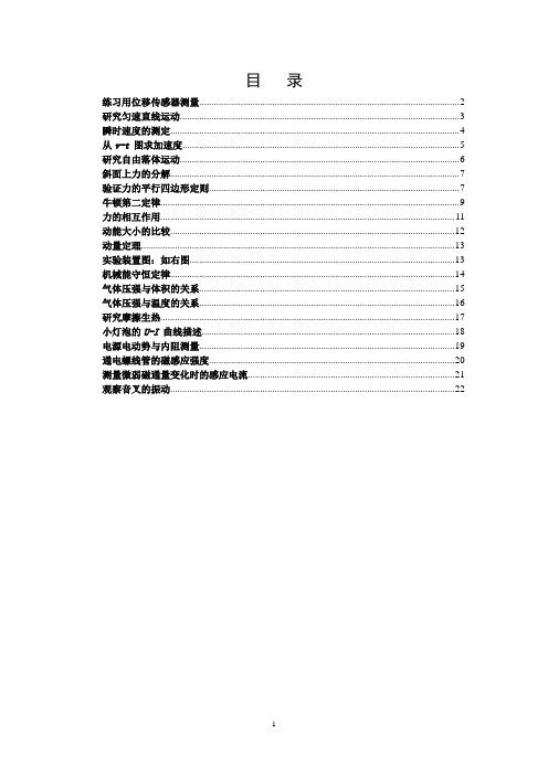
目录练习用位移传感器测量 (2)研究匀速直线运动 (3)瞬时速度的测定 (4)从v-t 图求加速度 (5)研究自由落体运动 (6)斜面上力的分解 (7)验证力的平行四边形定则 (7)牛顿第二定律 (9)力的相互作用 (11)动能大小的比较 (12)动量定理 (13)实验装置图:如右图 (13)机械能守恒定律 (14)气体压强与体积的关系 (15)气体压强与温度的关系 (16)研究摩擦生热 (17)小灯泡的U-I 曲线描述 (18)电源电动势与内阻测量 (19)通电螺线管的磁感应强度 (20)测量微弱磁通量变化时的感应电流 (20)观察音叉的振动 (21)练习用位移传感器测量►实验器材:数据采集器、计算机、位移传感器。
刻度米尺►实验操作(1)把刻度尺平放在实验台上;把位移传感器接收端放在刻度尺的一端,连接到数据采集器的2号口。
位移传感器的发射端置于刻度尺上某一适当位置(发射口与接收口相对)。
(2)双击图标,打开DAS程序,单击“新课改实验”,单击实验条目“练习使用DIS”,打开该软件。
点击,进入实验界面。
(3)打开发射端电源开关,点击“开始实验”,此时界面上会显示接受端和发射端的距离值。
(4)测位移。
点按数据采集器2号口置零按钮,为位移传感器“校零”,此时界面数据显示变为0.0cm。
(5)沿刻度尺移动发射端,界面上同时显示发生的位移值。
把位移传感器测得的值和利用导轨刻度尺上测出的值,填入下表1-1中进行比较,了解位移传感器的测量精度,采集多组数据后,关闭位移传感器发射端的电源。
表1-1(6)观察位移传感器的测量范围1)观察传感器可测量的最小(最大)距离。
打开发射端电源,如下图所示,把发射端沿轴线靠近(远离)接收端,当界面显示的数据不改变时,这就是可测量的最小(最大)距离。
这个距离可以从导轨的刻度尺上读出。
2)让发射端离接收端80cm,然后使发射端离开轴线向两侧偏离。
观察当偏离多远距离时,不能测量了。
雪迪龙烟气在线监测系统(CEMS)技术资料

选用的是电加热直接抽取法,由下列几个部件组成:
*采样头:ф35mm不锈钢管,伸进烟道1M处左右位置,样气通过此管进入采样器。 *碳化硅陶瓷过滤器:过滤精度为5-10μm,烟道中尘埃绝大部分被挡在过滤器之外 *电加热管:为防止在采样单元结水而建立的。电加热温度控制在180℃ 左右。 * 法兰对接:采样单元法兰与工艺管口法兰相对接,完成采样单元安装。 * 金属固定支架外壳:采样单元各部件有机地连接在一起,达到防雨防尘的目的。
SDL公司坚持用企业文化提升企业核心竞争力,使企业在发展中树立起良好的 社会形象。以“振兴分析仪器民族工业”为己任,一如既往的为顾客提供最合适气
体分 析解决方案。
公司在上海、武汉、广州、江西、香港等地设有办事处。
烟气连续监测系统
CEMS
中国烟气排放的有关法规
《火电厂大气污染物排放标准》
GB13223-96
数据采集、处理和控制系统
检测信号传输
监测
4. 数据采集、处理和控制系统 4.1 检测数据
气体浓度参数 尘埃浓度参数 气体流量参数 湿度参数 温度、压力参数
CEMS系统图
烟囱
分析室
样气预处理系统
分析柜
电控柜
CEMS系统图
环保局
组成
4.2 组成 ▪ 可编程逻辑控制器(PLC) ▪ 数据处理及控制子系统(DAS) DELL计算机 显示器 打印机 UPS
近似计算法:测量干氧和湿氧含量 干氧——由U23直接测量 湿氧——用氧化锆分析仪测量 计算公式: O2%(湿氧)
H2O %=100(1- ------------- )+0.8% O2 % (干氧)
特点
较高的测量精度,稳定性 流量计无活动部件,可以在较恶劣条件下使用 适用范围广,使用寿命与测量量程之比为100:1 介质温度适用范围广,从-40 ℃ ——400 ℃
CEMS系统检修、运行操作规程(试行)
CEMS系统检修、运行操作规程(试行)一、CEMS厂家规定要求1、本系统应由专职人员操作,操作人员在使用和维护本系统前先仔细阅读其使用手册;2、本系统中有危险电源盒热源,上电操作维护时应注意人身安全;3、本系统中烟气分析仪分析的气体含SO2、NOx、CO等对人体有害的气体,在仪表间操作维护时应注意保持通风良好,并保证系统排气管(至室外)畅通;4、要保持仪表室内的公用条件正常(照明、空调、通风风机等);5、系统在正常运行时应置于“自动”运行状态;6、要坚持定期巡检制度,并保证巡检记录完整;7、未经允许情况下严禁关断系统供电电源,测尘仪风机电源,在烟道测尘仪设备未拆离烟道时严禁断开;8、储液罐中的冷凝水具有腐蚀性,应定期排至安全泄放处;9、在非手动校准期间,仪表室内的标准气钢瓶总阀应处于关闭状态,并安全码放;10、系统中的至于烟道的设备严禁擅自调动和移动;11、DAS系统计算机应专用,严禁安装其他与本系统无关的软件。
二、CEMS系统设备启动准备1、保持仪器室的清洁和温度、湿度适宜;2、电源、气源、设备接地是否正常,排水、排气是否正常。
三、CEMS的启动操作1、依次启动采样探头,取样管路的加热设备,冷凝制冷器,使之达到规定的温度值;2、启动压缩空气气源,调节各环节压力达到规定值;3、采样气路吹扫15-30分钟之后;4、满足第1点、第2点和第3点时,启动烟气监测仪、流速、烟尘和其他仪表预热稳定运行30分钟;5、启动气体采样泵和排水泵;6、再启动数据采集处理系统(DAS系统)。
四、CEMS数据的检查1、全面检查CEMS数据报表,超标记录和运行记录,异常数据记录;2、检查异常数据与污染源治理设施运行工况是否相符;3、做DAS系统的日常维护,做CEMS历史数据的备份。
五、CEMS系统设备停用操作1、关闭数据采集器系统(DAS系统),停止无效的时间记录;2、采样预处理系统切换到吹扫状态,吹扫5-10分钟;3、依次关闭气体分析仪,冷凝器,压缩空气;4、最后关闭采样探头和烟气取样关管路的加热器。
技术文档5-PASS系统统计分析工作站安装及使用手册

医疗机构应用PASS系统统计分析工作站操作手册年月目录1. 安装 (3)1.1安装服务端 (3)1.1.1拷贝文件 (3)1.1.2附加统计分析库 (3)1.1.3配置服统计分析服务 (4)1.1.4安装与启动统计分析服务 (5)1.2安装客户端 (6)2.使用 (7)2.1服务端 (7)2.1.1启动统计分析服务程序 (7)2.2统计分析工作站使用 (7)2.2.1登录界面 (7)2.2.2统计范围设置界面 (8)2.2.3统计分析主界面 (8)2.2.4 PASS监测结果问题明细清单表 (9)2.2.5 PASS监测结果问题-审查类型统计表 (10)2.2.6PASS监测结果科室问题-审查类型统计表 (11)2.2.7PASS监测结果医生问题-审查类型统计表 (12)2.2.8 PASS监测结果问题-警示级别统计表 (12)2.2.9PASS监测结果科室问题-警示级别统计表 (13)2.2.10 PASS监测结果医生问题-警示级别统计表 (14)2.2.11 PASS监测结果药品-审查类型统计表 (15)2.2.12 PASS监测结果药品-警示级别统计表 (15)2.2.13 筛选界面 (16)2.2.14 用户管理 (17)加粗标识的部分,是需要特别注意的地方。
统计分析数据来源于PASS服务对医生工作站问题医嘱的采集,其中采集的数据随医嘱提交行为执行,数据保存在medicomsave数据库中,发生医嘱行为的次日就会对问题医嘱导入到ClinicStat数据库中,以便临床药师使用统计分析工作站对该院问题医嘱进行查询,以此为平台加强与医生的交流,减少或杜绝不合理用药现象的发生。
统计分析程序建议使用SQLServer数据库,如需要使用ORACLE数据库,则首先要运行产品光盘所在路径下的StaticServer\database目录里面的CreateClinicDB_oracle.sql文件,进行统计分析库及相关表的创建;下面的操作指南以SQLServer数据库类型为例进行介绍,除1.1.2附加统计分析库相关操作与ORACLE类型不同需运行上述脚本外,其它方法一致。
SPA RP-D 消火系统安装手册说明书

1 SPA DESIGN Fire Suppression manual for RP-D T hank you for purchasing one of our latest range of systems Homologated to the latest FIA standard 8865-2015. This manual covers the following systems RP-DIt is important that you read the following instructions carefully before attempting to install your fire suppression systems.T he performance of these systems could be affected if they are in any waymodified or tampered with and will void its homologation. Please ensure you only use genuine SPA parts should any part need replacing.Should you require assistance with this please call +44(0)1543 434580 or ********************.uk Pages 2-34 5-67-111213-14 15-1617IndexContentsSystem fitting instructionsElectrical installationEngine bay /cockpit nozzlelocationConnecting Copper pipeSystem picturesBottle dimensionsData sheetsInstallation Notes 1821 X SPA-EX-E-APS-B BOTTLE ONLY1 X SP278 BOTTLE PLINTH2 X SP279 BOLTED STRAPS2 X SP280 10MM COPPER PIPE PER METER1 X SP281 DEFLECTOR NOZZLE1 X SP282 BULKHEAD CONNECTOR ¼ BSP-M201 X SP283 10mm ¼ BSP COMPRESSION FITTING1 X SPA-eX-APS-B BOTTLE ONLY1 X SP278 BOTTLE PLINTH2 X SP279 BOLTED STRAPS1 X SP281 DEFLECTOR NOZZLE1 X SP288 ½ METER 12.7MM COPPER PIPE1 X SP282 BULKHEAD CONNECTOR ¼ BSP-M201 X SP287 EXTENSION PIPE1 X SP289 12.7MM ¼ BSP COMPRESSION FITTINGELECTRICAL KIT3 X SP005H HIRSCHMAN PLUG & LEADS1 X SP277 NEW FIA STANDARD POWER PACK HIRSCHMAN TYPE 1 x SP011 INTERNAL FIRE BUTTON1 X SP012 EXTERNAL FIRE BUTTON1 X SP017 E LOCATION STICKER LARGE1 X SP129 E LOCATION STICKER SMALLSYSTEM FITTING INSTRUCTIONSU npack all parts and check co mponents against check list on pages 2 & 3.Mount the engine bay system in or around the passenger footwell ideally in a transverse position pages 7-11Mount the cockpit system ideally as detailed on page s7-11 behind driver or passenger seat.The extinguisher label, detailing contents etc. should be visible, mount the plinth securely to the vehicle and secure the bottle with the straps provided.Mount the power pack in a clearly visible position.Switch with Shroud (SP011) to be fitted in the cockpit within easy reach of both driver and co-driver when sitting in normal driving position and wearing fastened seatbelts.External switch (SP012) to be fitted to outside of vehicle, close to master switch (to activate by marshals when required).Electrical system to be wired as shown on page 6.TEST POSITIONWith the switch in the test position, the power pack is not armed and draws no current until either the internal switch (SP011) or external switch (SP012) is pressed.To initiate the test routine, press either internal or external switch .Test all goodIf all the tests are good, the n the amber test lamp will light for 6 seconds and then go off. This means that the system has not been operated and the Co2 canister is still charged and all wiring continuity is good. Test failedIf one of the tests fails, the amber light will flash the fault indication for 12 seconds and go off.Fault IndicationIf the amber test lamp flashes one pulse at a time, this is error 1 = low batteryIf the amber test lamp flashes two pulses at a time, this is error 2 = Continuity Ohms too highIf there is a short in the wiring or if the firing button is not released, then the amber light will change from good (no flashing) to error (flashing error 3) after 6 seconds.If the amber test lamp flashes three pulses at a time , this is error 3 = short circuitWarning error 3 will continue to flash until the fault is removed – DO NOT switch system to armed if error 3 is flashing as this may operate the fire suppression systems, you must locate the fault in the wiring harness or switches.If no lights come on when you press the button, then there is no continuity. This can be due to a loom fault, a switch fault, an expended firing head, incorrect wiring, firing head not plugged in or a flat battery (check the battery by disconnecting the loom and momentarily switching to Armed position).ARMED POSTION With the switch in armed position, the power pack is providing full battery power to the output socket. If power pack switch and the battery volts are good, then the Red Armed LED will flash constantly. The Red LED only uses a very small amount of power; the battery should be replaced every 6 Test positionSystem armed position2 SYSTEM WIRINGSINGLE SYSTEM WIRING1.INSTALLATION DU SYSTEME D’EXTINCTION / FIRE EXTINGUISHER SYSTEM INSTALLATION101.INSTALLATION DANS L’HABITACLE / COCKPIT INSTALLATIONa)Emplacement et orientation du corpsLocation and orientation of bodyHorizontally mounted behind driver or passenger seatb)Emplacement et orientation des busesLocation and orientation of nozzlesLocated between driver and passenger seatc)Précaution à prendre lors de l’installation du systèmeSpecial care to take with the installation of the system Important do not obstruct the nozzle especially the space above itas the gas needs to reach the roof of the vehicle.E1-1) Installation dans l’habitacle (emplacement et orientation du corps)Cockpit installation (location and orientation of body) E1-2) Installation dans l’habitacle (emplacement et orientation des buses)Cockpit installation (location and orientation of nozzles)102.INSTALLATION DANS LE MOTEUR / ENGINE INSTALLATIONa)Emplacement et orientation du corpsLocation and orientation of body Horizontally mounted, behind driver or co-driver seat or in front ofdriver or co-driver seat.b)Emplacement et orientation des busesLocation and orientation of nozzlesMount off bulkhead central to engine.c)Précaution à prendre lors de l’installation du systèmeSpecial care to take with the installation of the systemEnsure all fittings are secure.E2-1) Installation dans le moteur (emplacement et orientation du corps)Engine installation (location and orientation of body) E2-2) Installation dans le moteur (emplacement et orientation des buses)Engine installation (location and orientation of nozzles)ENGINE NOZZLE LOCATIONNozzle locationBOTTLE LOCATION ENGINE Ideally m ount bottle in passenger footwell areaDEFLECTOR NOZZLE ORIENTATION ENGINE BAYRP-DNozzle locationIdeally m ount cockpit bottle either behind driver seat or passenger seatENG INE BAY NOZZLE CONNECTIONSSINGLE OUTLET RP-DThe engine bay Nozzle comes preassembled.1.Measure length of pipe required, cut to size using pipe cutter or hacksaw, deburr pipe.2.Push one end of pipe into 10mm fitting on bottle.3.Make 21mm hole in bulkhead.4.Insert bulkhead Fitting into hole from engine bay side5.Keep Deflector nozzle in position as shown on page 86.Turn M20 nut onto bulkhead Fitting until tight against bulkhead7.Screw ¼ BSP compression fitting into bulkhead connector until tight8.Place Compression nut and then olive onto 10mm pipe9.Insert pipe into compression fitting and tighten using two spannersCONNECTING COPPER PIPE – COMPRESSION FITTINGSOnce the pipes have been cut square – make sure all components are clean; you can use steel wool for this.Place the first nut over one of the sections of pipe.Next, place the olive over the pipe and push it along a little. Some olives have a right and wrong way round. If this is the case, they will have a different size chamfer on each side.The longest one goes against the middle of the joint.Place the fitting over the pipe and push it home. Line up the nut and hand-tighten.Using two spanners, hold the body of the fitting still with one, whilst tightening the nut with the other. It is important to tighten this nut by the right amount. If it is not fully tightened, the joint could leak.If the nut is over tightened, the olive and pipe can become distorted and the connection will leak. As a guide, the nut will usually require one complete revolution in addition to the hand-tightening. As the spanner is turned, you will feel some obvious resistance as the olive is pushed against the pipe. At this point, it will only need a little additional tightening to become watertight.This routine is to be applied to all compression fittings where pipework is connected.SYSTEM IMAGESCOCKPIT SYSTEMRP-DENGINE BAY SYSTEMS114 RP-D15 BOTTLE DIMENSIONS ALUMINIUM BOTTLEBOTTLE DIMENSIONS CARBON BOTTLEData sheetsEXTREMEComposition Dodecafluoro-2-methylpentan-3-one,(CF3CF2C(O)CF(CF3)2)Ozone depletion NoneOperating temperature -40 to + 85 CFreeze point -108 CCritical temperature 168.7 CPhysiological properties no observed adverse effect level and lowest observed adverse effect level for cardiac sensitization (halocarbons) and oxygen depletion (Inert gas)INSTALLATION NOTESWhen removing straps on the cockpit systems andsingle outlet systems for the engine it may be necessaryto rotate the charge cylinder for ease of fitments.Remove the four Allen bolts from the bracket and put ina safe place. Fig 1Gently lift the charge cylinder out of the bracket androtate to the left, it will rotate around the fitting asshown in Fig 2 & 3.You may now adjust the straps or remove the bottlefrom the mounting plinth Fig 3. Please remember toreplace the top mounting bracket and Allen boltsNozzle installation, install the bulkhead fitting as shownon page 11, apply a small amount of Loctite 243 orequivalent threadlocking medium strength adhesive toprevent vibration Fig 4.Now rotate the nozzle into the correct position as shownon page 8 or 9 and allow threadlocking adhesive to cureas shown in Fig 5fig 1fig 2fig 3fig 4fig 5。
Sundance Spas 设备系统安装说明书

3
Connecting Pipes Between Spa and Equipment
3
Electrical Installation Instructions
5
Power Supply Requirements
7
Use of External Heater
8
External Electric Heater
11
Connecting the Spa Light
11
Connecting the Temperature Sensor
12
Remote Freeze Protection Sensor
12
Start Up
13
Testing the Installation
14
Important Notices
Sundance® Spas
SPA PMENT
SYSTEM
Installation Instructions
P/N 6530-456 Rev. A
Contents
Important Notices
1
Important Safety Instructions
2
Where to Place the Equipment System
7. The electrical circuit supplied for the spa must include a suitable ground fault circuit interrupter (GFCI) as required by NEC Article 68042.
8. READ AND FOLLOW THE OWNER OPERATING INSTRUCTIONS PROVIDED BEFORE USING THE SPA.
固定污染源烟气排放连续监测系统 运营管理操作规程

固定污染源烟气排放连续监测系统运营管理操作规程第一章总则1.为加强本公司运营人员对固定污染源烟气排放连续监测系统在现场的设备管理、工艺管理和气态污染物排放的实施准确性,保证固定污染源烟气排放连续监测系统的正常运行,达到相关环保法律法规的要求,实现向上级主管部门、环保部门等监管部门的数据传输,实时准确的反应固定污染源的排污状况,保护环境的目的,特制订本规程。
2.本单位所负责的的固定污染源连续监测系统的运行、维护及各故障处理除应符合本规程外,还应严格执行和符合国家相关标准和各行业标准。
第二章运行管理1运行管理要求1.1负责设备运行的人员必须熟悉所负责运营的固定污染源烟气排放连续监测系统的测量原理、工艺流程、维护制度、操作规范以及设备的运行要求、运行环境和各技术性能指标;1.2操作人员必须了解本单位系统的电气控制原理、各仪表测量原理、气路流程原理,熟悉和掌握本单位设备常见故障现象及维护方法、设备操作使用说明书等文件;1.3各分析小屋及设备需配备必须的操作使用说明书、安全操作规程、电气控制原理图、巡检记录表格、维护/维修记录表格、常用备品备件更换记录表格等文件,并置放于明显部位;1.4负责运营管理的操作人员应严格按照设备使用说明书的要求按时、按期的对所主管的运营设备进行巡视检查各现场一次仪表的运行状态、分析小屋内气体预处理装置的运行状态、校准/排水的运行状态,并做好相应记录;1.5各运营操作人员要严格按照设备的使用说明说或操作维护手册进行相关工作,并做好相关表格记录,保证数据的准确性,设备运行的可靠性;1.6操作人人如在巡检或维护中,发现设备运行不正常,应及时处理,并做好记录,如短时间内无法恢复设备的正常运行,应及时上报上级主管部门,必要时,以书面要求向上级主管部门申请暂停设备运营并申请相关备用设备,以保证现场的正常运行;1.7操作人员应保证负责范围内设备分析小屋内卫生状态良好,仪表柜表面没有积灰,各气路管道内部干净,无附着物,各过滤器滤芯内部无明显结垢,排水容器内无冷凝水溢出;1.8根据不同设备的要求,要定期检查、更换各易损易耗件及各气路管路,并做好相应的记录。
DAS 软件 说明书

第 2 页,共 41 页
更新日期:9/18/2007
DAS 软件用户手册
非房室模型的统计矩分析.....................................................................14 药物相互作用分析与复方药效模拟..........................................................15 权重配方法介绍 ...............................................................................26 药物相互作用反映曲面分析 ..................................................................35 临床 EC50 计算 ...............................................................................39
第 3 页,共 41 页
DAS 软件用户手册
(正在编写中,不断更新,请经常上网下载)
技术支持: 201203 上海 浦东 张江,郑青山 教授 021-51323006,13817078595ຫໍສະໝຸດ Email: drugchina@
升级与购买: 查询网站 联系人:刘红霞 老师 电话:021-51323006,15921008232 传真:021-51322750 Email: drugchina@
PAS-DAS软件用户手册
用户使用手册(V2.0)
北京雪迪龙科技股份有限公司
I
目录
1 简介 ............................................................................................................................................................. 1 1.1 定义 ................................................................................................................................................. 1 1.2 参考文献.........................................................................................................................................1 1.3 系统结构.........................................................................................................................................2
II
5.5 实时曲线.......................................................................................................................................22 5.6 历史数据.......................................................................................................................................22 5.7 报警信息........................................................................................................................................25 5.8 系统框图........................................................................................................................................25 5.9 数据审核........................................................................................................................................26 5.10 数据转发......................................................................................................................................26 6 技术支持 .................................................................................................................................................. 27
WordiFixSCADA软件教程-2024鲜版(1)

DA软件教程•软件介绍与安装•基本功能与操作•高级功能与扩展•案例分析与实践操作目录•故障诊断与维护保养•总结与展望软件介绍与安装01CATALOGUEWordiFixSCADA是一款功能强大的工业自动化监控和数据采集(SCADA)软件。
它提供了丰富的功能和工具,用于监控、控制和优化工业过程。
WordiFixSCADA支持多种通信协议和设备接口,可以与各种工业设备和系统无缝集成。
010203 WordiFixSCADA软件概述01操作系统Windows 7及以上版本,64位系统。
02处理器Intel 或AMD 多核处理器,2.0 GHz 或更高。
03内存至少4GB RAM ,推荐8GB 或更多。
04硬盘空间至少10GB 可用硬盘空间。
05显示器分辨率为1280x768或更高。
06兼容性WordiFixSCADA 与大多数工业设备和系统兼容,包括PLC 、传感器、执行器等。
系统需求与兼容性0102031. 下载WordiFixSCADA 安装程序,并解压缩到本地目录。
2. 运行安装程序,按照提示进行安装。
3. 在安装过程中,选择安装目录和组件。
•安装完成后,启动WordiFixSCADA软件。
注意事项在安装之前,请确保您的计算机满足系统需求。
关闭所有正在运行的程序,以避免安装过程中的冲突。
如果您已经安装了旧版本的WordiFixSCADA,请先卸载旧版本再安装新版本。
常见问题及解决方法1. 问题无法安装WordiFixSCADA软件。
解决方法检查您的计算机是否满足系统需求,并尝试以管理员身份运行安装程序。
2. 问题安装完成后无法启动WordiFixSCADA软件。
解决方法检查您的计算机是否有足够的内存和硬盘空间,并尝试重新安装软件。
3. 问题无法与工业设备通信。
解决方法检查设备连接和通信协议设置是否正确,并确保设备与WordiFixSCADA软件兼容。
基本功能与操作02CATALOGUE显示系统运行状态、实时数据、报警信息等。
电力调度自动化系统中PAS软件的应用

电力调度自动化系统中PAS软件的应用摘要:随着信息技术的快速发展以及电网规模的不断扩大,原来的以人工管理和电话通信为主要手段的电网调度工作方式己经无法适应当前的业务需求,采用分布式网络通信技术以及计算机软件技术为核心的电网调度自动化系统己经成为当前电力系统日常管理工作的重要方式。
本文首先概述了电力调度自动化系统的作用,接着着重分析电力调度自动化系统中PAS软件的应用关键词:电力调度;自动化系统;PAS软件引言电网调度自动化系统对于电力系统电力基础设施的安全稳定运行有着重要意义,能够以自动化的工作方式对变电站系统进行远程管理,为电力系统各级调度中心提供更为详实的电网运行以及变电站运行实时数据,为电网调度人员提供工作参考依据,是未来电网调度工作的重要发展趋势。
随着电网在运行和管理需求方面的层级提升,电网结构趋于复杂化、多层次化发展,要保证电力生产更加安全有序,诸多电力企业通过安装PAS高级应用软件来维护电网的稳定安全运行。
1、电网调度自动化系统的功能按照目前国内外电力系统的电网调度自动化系统的功能设置,在典型的电网调度自动化系统中一般需要包括电网运行数据的采集和处理、电网运行的安全监控与管理操作、事件信息的自动化记录处理、异常与故障的自动化报警和应对、人际交互以及现场RTU管理功能等方面。
(1)电网调度自动化系统首先需要能够实现电网运行状态的数据采集功能,例如主变状态信息采集、模拟量、状态量、脉冲量和相关保护信息的自动采集,这部分功能通常直接通过SCADA系统的功能体系来实现。
同时在数据采集基础上,在电网调度自动化系统中还需要实现这些数据采集结果的简单统计运算、可靠性检查以及安全阈值检查等基本功能,例如负荷情况、主变负荷、电压功率情况以及故障信息等方面的基本分析功能。
(2)安全监控与管理操作是指在电网调度自动化系统中能够对电网运行的安全状态信息进行自动监控,这些安全状态通过SCADA中的数据采集功能来实现,在其中集成数据展示、异常报警以及事故处理信息的自动化记录,并且能够在画面中以多种形式记录下电网主变负荷信息、开关状态信息、接地装置信息等,包括正常信息和异常信息两个方面。
