SGF系列双筒高压过滤器(新型)
常用的油滤芯型号有哪些

常⽤的油滤芯型号有哪些常⽤的油滤芯型号有哪些?关于这个问题的答案,有点难以回答,不是⼩编不知道油滤芯型号有哪些,⽽是油滤芯型号太多了,即便是只说常⽤的,也还是太多了!因此,请允许我们想⼀个折中的办法:下⾯艾达以黎明液压油滤芯为例,为⼤家说⼀说常⽤的油滤芯型号吧。
1、QYL型回油过滤器滤芯型号:QYLX-63×*Q2、QYLX-100×*Q2、QYLX-160×*Q2、QYLX-250×*Q2、QYLX-400×*Q2(*分别代表3,5,10,20,30)2、GU-H系列⾃封式压⼒管路过滤器滤芯型号:GX-10×*、GX-25×*、GX-40×*、GX-63×*、GX-100×*、GX-160×*、GX-250x*、GX-400×*、GX-630×*(*分别代表3,5,10,20,30,40)3、ISV系列管路吸油过滤器滤芯型号:IX-40×*、IX-63×*、IX-100×*、IX-160×*、IX-250×*、IX-400×*、IX-630×*、IX-800×*、IX-1000×*(*分别代表80,100,180)4、ZU-A,QU-A,WU-A系列回油过滤器滤芯型号:TZX2-10×*、TZX2-25×*、TZX2-40×*、TZX2-63×*、TZX2-100×*、TZX2-160×*、TZX2-250×*、TZX2-400×*、TZX2-630×*、TZX2-800×*、TZX2-1000×*(*分别代表1,3,5,10,20,30)5、XU-A系列回油过滤器滤芯型号:TXX-25×* TXX-40×* TXX-63×* TXX-100×* TXX-160X* TXX-250×* TXX-400×* TXX-630×*(*分别代表30,50)6、TFB系列吸油过滤器滤芯型号:TFBX-45×*、TFBX-70×*(*分别代表10,20,30,80)7、XNL系列箱内回油过滤器滤芯型号:NLX-25×*、NLX-40×*、NLX-63×*、NLX-100×*、NLX-160×*、NLX-250×*、NLX-400×*、NLX-630×*、NLX-800×*、NLX-1000×*(*分别代表3,5,10,20,30)8、旋装式管路过滤器滤芯型号:SPX-06×10、SPX-06×25、SPX-08×10、SPX-08×25、SPX-10×10、SPX-10×25、SPAX-10×109、SRFA系列双筒微型直回式回油过滤器滤芯型号:SFAX-25×*、SFAX-40×*、SFAX-63×*、SFAX-100×*、SFAX-160×*、SFAX-250×*、SFAX-400×*、SFAX-630×*、SFAX-800×*(*分别代表1,3,5,10,20,30)10、SRFB系列双筒直回式回油过滤器滤芯型号:SFBX-25×*、SFBX-40×*、SFBX-63×*、SFBX-100×*、SFBX-160×*、SFBX-250×*、SFBX-400×*、SFBX-630×*、SFBX-800×*、SFBX-1000×*、SFBX-1300×*(*分别代表1,3,5,10,20,30)11、SRLF系列双筒回油管路过滤器滤芯型号:SFX-60×*、SFX-110×*、SFX-160×*、SFX-240×*、SFX-330×*、SFX-500×*、SFX-660×*、SFX-850×*、SFX-950×*、SFX-1300×*(*分别代表1,3,5,10,20,30,40)12、SXU-A系列双筒回油过滤器滤芯型号:STXX-25×*、STXX-40×*、STXX-63×*、STXX-100×*、STXX-160×*、STXX-250×*、STXX-400×*(*分别代表30,50)13、SGF系列双筒⾼压过滤器滤芯型号:PLFX-30×*(*分别代表3,5,10,20)14、XU-A系列回油过滤器滤芯型号:TXX-25×*、TXX-40×*、TXX-63×*、TXX-100×*、TXX-160X*、TXX-250×*、TXX-400×*、TXX-630×*(*分别代表30,50)15、RFA系列微型直回式回油过滤器滤芯型号:FAX-25×*、FAX-40×*、FAX-63×*、FAX-160×*、FAX-250×*、FAX-400×*、FAX-630×*、FAX-800×*、FAX-1000×*(*分别代表1,3,5,10,20,30)16、RFB系列直回⾃封式磁性回油过滤器滤芯型号:FBX-25×*、FBX-40×*、FBX-63×*、FBX-100×*、FBX-160×*、FBX-250×*、FBX-400×*、FBX-630×*、FBX-800×*、FBX-1000×*、FBX-1300×*(*分别代表1,3,5,10,20,30)当然,上列油滤芯型号全部都是黎明滤芯,⽽且只是部分滤芯型号,如需了解更多油滤芯型号信息,欢迎随时来电咨询。
各种过滤器样本(南通飞特尔)

YQXP II 型过滤器
YQXC I 型复合式在线手动清洗过滤器
注意事项 YQX 型在线式手动清洗过滤器可水平或垂直安装,安装时应注意外壳上箭头方向必须与水流方向一致。
订货须知 (1)、本公司生产的 ZJS 系列过滤器,公称压力等级为 0.6、1.0、1.6、2.5、4.0、6.3MPa,采用化工部 HG20592 标准,用户
过滤器是工业生产中不可缺少的管道设备,安装在管道上能除去流体中的固体杂质,使机器设备(包括压缩机、泵等),仪表 正常工作和运转,达到稳定工艺过程,保障安全生产的作用。另外对提高产品质量也有十分重要的意义。
本公司生产的普通过滤器具有结构紧凑、过滤能力大、压损小,适用范围广、维护方便、价格低廉等优点。 公司新近推出的智能过滤器系列产品,除具有普通过滤器的所有功能外,同时还具有提供更换、清洗滤网信息的樗和远程声光 报警功能,它的基本原理是利用流经过滤器流体入口与出口的压力差,使智能器内压差式信息发生动作,在智能器一端的红圆柱便 冒出或发生报警信息,表示滤网被阻塞需要更换或清洗。它克服了当今普通过滤器因无法及时指示滤网的阻塞程度而造成断流、烧 泵或误判滤网阻塞白白浪费入力、物力等弊端,是一种理想的更新换代产品。若将它串联地安装在泵的入口或系统管线的其它部位, 既可处长泵和其它设备的使用寿命,又能保证整个系统安全。
规格型号与技术参数
正向流锥形式临时过滤器
反向流锥形式临时过滤器
在线式手动清洗过滤器 产品简介
YQX 系列在线式手动清洗过滤器适用于各种供水系统、工艺管路及工业循环水系统,特别是 24 小时连续运行的不停机系统, 确保系 统的安全可靠运行,是一种简洁高效的过滤器,广泛应用于石油、化工、冶金、环保、采矿、制药、食品、造纸等领域。
H 400 450 500 550 600 650 750 1020 1240 1310
中国华电集团公司火力发电工程设计导则(B版)
中国华电集团公司火力发电工程设计导则(B版)中国华电集团公司2015年6月北京中国华电集团公司火力发电工程设计导则(B版)编制单位:华电技术经济研究院批准部门:中国华电集团公司中国华电集团公司前言《中国华电集团公司火力发电工程设计导则(A版)》(以下简称“导则(A 版)”)自2005年7月颁布后已执行十余年。
近年来随着国家火电项目产业政策的变化,新的《大中型火力发电厂设计规范》(GB50660-2011)、《火电厂大气污染物排放标准》(GB13223-2011)、《煤电节能减排升级与改造行动计划(2014—2020年)》等陆续印发,电力行业新技术、新设备不断发展,集团公司的火电工程建设目标也转变为建设“安全优质、高效环保、指标先进、竞争力强”的电厂,2015年又提出了更高的“三同领先”要求,为积极响应这些变化和要求,更好的指导火电项目开展初步设计及优化工作,在总结导则(A版)实施经验教训的基础上,集团公司于2013年3月启动对导则(A版)进行修编。
2013年10月完成导则修编的征求意见稿,2013年11月集团公司有关部门及二级机构进行了内部评审,2014年2月委托电力规划设计总院进行了全面的评审,至2015年5月全面完成了《中国华电集团公司火力发电工程设计导则(B版)》(以下简称“导则(B版)”)的修编工作。
本导则共分21章。
主要技术内容有:总则,厂址选择,总体规划,机组选型,主厂房区域布置,运煤系统,锅炉设备及系统,除灰渣系统,烟气脱硫系统,烟气脱硝系统,汽轮机设备及系统,水处理系统,信息系统,仪表与控制,电气设备及系统,水工设施及系统,辅助及附属设施,建筑与结构,采暖通风,环境保护,劳动安全职业卫生。
本导则由中国华电集团公司火电产业部归口管理,由华电技术经济研究院负责具体内容解释。
执行过程中如有意见或建议,请及时反馈华电技术经济研究院,以便今后修订时参考。
目录1 总则............................................................................................................................... - 1 -2 厂址选择................................................................................................................................. -3 -2.1 基本规定........................................................................................................................ - 3 -2.2 厂址自然条件................................................................................................................ - 4 -2.3 建厂资源条件................................................................................................................ - 7 -2.4 国家及地方环境保护政策.......................................................................................... - 10 -2.5 发电厂选址其他要求.................................................................................................. - 11 -3 总体规划............................................................................................................................... - 12 -3.1 基本规定...................................................................................................................... - 12 -3.2 厂区外部规划.............................................................................................................. - 13 -3.3 厂区规划及总平面布置.............................................................................................. - 13 -4 机组选型............................................................................................................................. - 16 -4.1 机组参数...................................................................................................................... - 16 -4.2 机组选型...................................................................................................................... - 18 -4.3 主机容量匹配.............................................................................................................. - 20 -5 主厂房区域布置................................................................................................................... - 21 -5.1 基本规定...................................................................................................................... - 21 -5.2 汽机房及除氧间布置.................................................................................................. - 21 -5.3 煤仓间布置.................................................................................................................. - 22 -5.4 锅炉布置...................................................................................................................... - 23 -5.5 集中控制室和电子设备间布置.................................................................................. - 23 -5.6 烟气脱硫设施布置...................................................................................................... - 24 -5.7 烟气脱硝设施布置...................................................................................................... - 24 -5.8 维护检修...................................................................................................................... - 25 -6 运煤系统............................................................................................................................... - 26 -6.1 基本规定...................................................................................................................... - 26 -6.2 卸煤设施...................................................................................................................... - 26 -6.3 贮煤场及其设备.......................................................................................................... - 28 -6.4 带式输送机系统.......................................................................................................... - 30 -6.5 筛碎设备...................................................................................................................... - 31 -6.6 混煤设施...................................................................................................................... - 32 -6.7 循环流化床锅炉运煤系统.......................................................................................... - 32 -6.8 运煤系统辅助设施...................................................................................................... - 32 -6.9 入厂煤入炉煤计量及采制化设施.............................................................................. - 33 -7 锅炉设备及系统..................................................................................................................... - 38 -7.1 锅炉设备...................................................................................................................... - 38 -7.2 煤粉制备...................................................................................................................... - 39 -7.3 烟风系统...................................................................................................................... - 42 -7.4 点火、助燃油系统及锅炉辅助系统.......................................................................... - 43 -7.5 启动锅炉...................................................................................................................... - 44 -7.6 循环流化床锅炉系统.................................................................................................. - 44 -7.7 进口配套产品和阀门.................................................................................................. - 44 -8 除灰渣系统............................................................................................................................. - 46 -8.1 基本规定...................................................................................................................... - 46 -8.2 除渣系统...................................................................................................................... - 46 -8.3 除灰系统...................................................................................................................... - 48 -8.4 干灰分选系统.............................................................................................................. - 49 -8.5 石子煤处理系统.......................................................................................................... - 50 -8.6 循环流化床锅炉除灰渣系统...................................................................................... - 50 -8.7 厂外干灰渣输送系统.................................................................................................. - 50 -8.8 除灰渣系统辅助检修设施和防护设施...................................................................... - 51 -8.9 除尘设备...................................................................................................................... - 51 -9 烟气脱硫系统....................................................................................................................... - 54 -9.1 基本规定...................................................................................................................... - 54 -9.2 吸收剂制备系统.......................................................................................................... - 55 -9.3 二氧化硫吸收系统...................................................................................................... - 57 -9.4烟气系统....................................................................................................................... - 58 -9.5 脱硫副产品处置系统.................................................................................................. - 59 -9.6 脱硫系统设备进口范围.............................................................................................. - 60 -10 烟气脱硝系统....................................................................................................................... - 61 -10.1 基本规定.................................................................................................................... - 61 -10.2 选择性催化还原烟气脱硝(SCR)工艺 ................................................................ - 62 -10.3 选择性非催化还原烟气脱硝(SNCR)工艺.......................................................... - 66 -11 汽轮机设备及系统............................................................................................................... - 67 -11.1 汽轮机设备................................................................................................................ - 67 -11.2 主蒸汽、再热及旁路系统........................................................................................ - 67 -11.3 给水及除氧系统........................................................................................................ - 68 -11.4 凝结水系统................................................................................................................ - 71 -11.5 辅机冷却水系统........................................................................................................ - 71 -11.6 供热式机组的辅助系统和设备 ................................................................................ - 72 -11.7 进口配套产品和阀门................................................................................................ - 72 -12 水处理系统........................................................................................................................... - 74 -12.1 基本规定.................................................................................................................... - 74 -12.2 锅炉补给水处理........................................................................................................ - 75 -12.3 汽轮机组凝结水精处理............................................................................................ - 81 -12.4 热力系统的化学加药................................................................................................ - 82 -12.5 热力系统的水汽取样及监测.................................................................................... - 83 -12.6 冷却水处理................................................................................................................ - 83 -12.7 热网补给水及生产回水处理.................................................................................... - 84 -12.8 制氢和供氢................................................................................................................ - 85 -12.9 废水处理及回用........................................................................................................ - 86 -13 信息系统............................................................................................................................... - 88 -13.1 基本规定.................................................................................................................... - 88 -13.2 信息系统总体规划.................................................................................................... - 88 -13.3 厂级监控信息系统.................................................................................................... - 89 -13.4 管理信息系统............................................................................................................ - 89 -13.5 视频监视系统............................................................................................................ - 91 -13.6 视频会议系统.......................................................................................................... - 91 -13.7 门禁管理系统............................................................................................................ - 92 -13.8 培训仿真机................................................................................................................ - 92 -13.9 信息安全.................................................................................................................... - 92 -14 仪表与控制........................................................................................................................... - 94 -14.1 基本规定.................................................................................................................... - 94 -14.2 自动化水平................................................................................................................ - 94 -14.3 控制方式.................................................................................................................... - 95 -14.4 集中控制室和电子设备间...................................................................................... - 95 -14.5 检测与仪表.............................................................................................................. - 96 -14.6 报警............................................................................................................................ - 97 -14.7 机组保护.................................................................................................................... - 97 -14.8 开关量控制................................................................................................................ - 98 -14.9 模拟量控制................................................................................................................ - 99 -14.10 机组控制系统.......................................................................................................... - 99 -14.11 辅助车间控制系统................................................................................................ - 102 -14.12 仪表与控制系统选型............................................................................................ - 103 -14.13 控制电源和气源.................................................................................................... - 103 -14.14 仪表与控制系统进口范围.................................................................................... - 104 -15 电气设备及系统................................................................................................................. - 105 -15.1 发电机与主变压器.................................................................................................. - 105 -15.2 电气主接线.............................................................................................................. - 106 -15.3 主要电气设备选择.................................................................................................. - 108 -15.4 厂用电系统.............................................................................................................. - 110 -15.5 电气设备布置.......................................................................................................... - 113 -15.6 直流系统及交流不间断电源.................................................................................. - 115 -15.7 励磁系统................................................................................................................ - 116 -15.8 电气监控及继电保护系统...................................................................................... - 116 -15.9 照明系统................................................................................................................ - 117 -16 水工设施及系统................................................................................................................. - 119 -16.1 水务管理.................................................................................................................. - 119 -16.2 供水系统.................................................................................................................. - 121 -16.3 取排水建筑物.......................................................................................................... - 122 -16.4 空冷系统.................................................................................................................. - 124 -16.5 湿式冷却塔.............................................................................................................. - 126 -16.6 给水和废水排放...................................................................................................... - 126 -16.7 贮灰场...................................................................................................................... - 127 -16.8水工专业试验........................................................................................................... - 128 -17 辅助及附属设施................................................................................................................. - 130 -17.1 基本规定.................................................................................................................. - 130 -17.2 辅助生产系统.......................................................................................................... - 130 -17.3 辅助建筑.................................................................................................................. - 131 -17.4 附属建筑.................................................................................................................. - 132 -17.5 辅助及附属建筑物建筑装修标准.......................................................................... - 134 -18 建筑与结构....................................................................................................................... - 136 -18.1 基本规定.................................................................................................................. - 136 -18.2 建筑设计.................................................................................................................. - 137 -18.3 主厂房结构.............................................................................................................. - 139 -18.4 地基与基础.............................................................................................................. - 140 -18.5 直接空冷构筑物...................................................................................................... - 141 -18.6 烟囱及烟道结构...................................................................................................... - 142 -18.7 运煤建(构)筑物.................................................................................................. - 142 -18.8 主厂房及集中控制室建筑装修标准...................................................................... - 143 -19 采暖、通风和空气调节................................................................................................... - 146 -19.1 基本规定.................................................................................................................. - 146 -19.2 主厂房采暖、通风.................................................................................................. - 146 -19.3 主厂房空气调节系统.............................................................................................. - 147 -19.4 制冷站...................................................................................................................... - 148 -19.5 采暖加热站.............................................................................................................. - 149 -19.6 厂区管道.................................................................................................................. - 149 -19.7 运煤系统采暖通风除尘.......................................................................................... - 149 -19.8 厂外取水和灰场建(构)筑物采暖通风空调 ...................................................... - 150 -19.9 脱硫、脱硝建筑通风空调除尘.............................................................................. - 150 -20 环境保护和水土保持......................................................................................................... - 152 -20.1 基本规定.................................................................................................................. - 152 -20.2 大气污染防治.......................................................................................................... - 152 -20.3废水利用及排放....................................................................................................... - 153 -20.4 厂区噪声污染防治.................................................................................................. - 154 -20.5 灰渣污染防治和综合利用...................................................................................... - 154 -20.6 清洁生产和总量控制.............................................................................................. - 154 -20.7 水土保持.................................................................................................................. - 155 -20.8 环境保护管理和监测.............................................................................................. - 156 -21 消防、劳动安全与职业卫生............................................................................................. - 157 -21.1 消防...................................................................................................................... - 157 -21.2 劳动安全.................................................................................................................. - 157 -21.3 职业卫生.................................................................................................................. - 158 -1 总则1.0.1 本导则适用于中国华电集团公司系统(以下简称:集团公司)及其全资、控股公司投资新建或扩建的国内燃煤火力发电工程,由集团公司投资建设、采用中国设计标准的境外燃煤火电工程可参照执行。
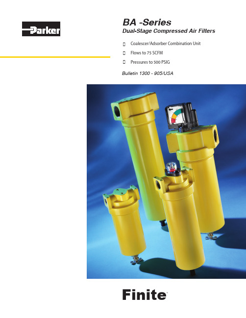
Finite BA-Series 双阶段压缩空气过滤器说明书
2
How it works
Port 1
Air In
4.65”
Port 2
Clean Air Out
Compressed air enters port #1 of the housing and is directed down
by means of a non-bypassing separation device. The second stage’s
BA-Series filters may also be used in applications requiring compressed air to be free of odor or taste bearing hydrocarbons. Food/beverage applications would be typical where compressed air comes in contact with the product. The BA-Series can also be used as a prefilter for critical needs such as zero air generators, membrane filters and many others!
Note: This product does not
element into the bowl where it is
remove toxic gases from the air
removed either manually, or by an
stream. A carbon monoxide moni-
Replacement elements are supplied in convenient repair kits which include one coalescing element, two activated carbon adsorber elements, and replacement seals. Two adsorber elements are supplied because the stage one coalescer will routinely outlive the extremely sensitive second stage adsorber element.
GRAF Optimax-XXL过滤器外装安装和维护说明书

Optimax XXL Filter externalItem no. 340096DN300 (12”) connection kit (USA)Item no. 340098DN400 (16”) connection kit (USA)Item no. 340100The points described in these in-structions must be observed under all circumstances. All warranty rights are invalidated in the event of non-observance. Separate in-stallation instructions are enclosed in the transportation packaging for all additional articles purchased from GRAF.Missing instructions must be re-quested from us immediately. The tank must be checked for any damage prior to insertion into the trench under all circumstances. Missing instructions can be down-loaded on or can be requested from GRAF.Contents1.GENERAL INFORMATION 9 1.1 Safety9 1.2 Identification obligation 9 2.INSTALLATION CONDITIONS 9 2.1 Optimax XXL Filter external 9 3.TRANSPORT AND STORAGE 10 3.1 Transport 10 3.2 Storage 10 4.TECHNICAL DATA10 5.INSTALLATION AND ASSEMBLY 11 5.1 Preparing the filter and piping11 5.2 Insertion and establishing connections 11 5.3 Connecting the filter cleaning unit 11 6.START-UP AND MAINTENANCE 12 6.1 Start-up12 6.2 Maintenance 12 6.3Cleaning121.1.1 SafetyThe relevant accident prevention regulations according to BGV C22 must be observed during all work. Particularly when walking on the tanks, a 2nd person is required to secure the tank.The relevant regulations and standards must additionally be taken into consideration during installation, assembly, servicing, repair, etc. Relevant notes can be found in the corresponding sections of these in-structions.During all work on the system or parts of the system, the entire system must always be rendered inopera-ble and secured to prevent unauthorised reactivation.GRAF offers an extensive range of accessories, all of which are designed to match each other and whichcan be extended to form complete systems. The use of other accessories may lead to impediments to the system's functional capability, therefore invalidating liability for resulting damage.1.2 Identification obligationAll service water pipes and outlets must be identified in writing with the words "Not drinking water" or inthe form of images (DIN 1988 Part 2, Para. 3.3.2.), this is to avoid inadvertent connection to or with the drinking water mains even after a number of years. Mix-ups, e.g. by children, may still occur even in the case of correct identification. All service water extraction points must therefore be installed with valves that have child-proof locks.2.2.1 Optimax XXL Filter externalThe GRAF Optimax XXL Filter external is designed for filtering rainwater within rainwater harvesting sys-tems. The low-maintenance, self-cleaning filter technology is patented and has a water yield of over 95%. Contaminants are automatically routed to the sewer via the sieve surface. The filter fabric can be cleaned using the filter cleaning unit incorporate within the product, without the need to disassemble the Optimax XXL Filter.∙The Optimax XXL Filter external is designed for installation in a pilot shaft or a cistern∙Direct installation in the ground without protection is not permitted∙Ensure that the inflow pipe is long enough to slow down the inflowing water.∙The roof area for connection to DN 300 (12”) = 3.000 m² (32.300 ft2), DN 400 (16”) = 6.000 m² (65.000 ft2)∙The height difference between inlet and outlet is 45 mm (1,7”)∙The mesh width of the stainless steel sieve insert is 0.35 mm (0,01”)∙Larger filter designs are available upon request.3.3.1 TransportThe filters must be secured to prevent shifting and falling during transport. If the filters are secured for transport using tension belts, make sure that the filters remain undamaged.Stress caused by impacts must be avoided. The filters must in no event be rolled or dragged across the ground.3.2 StorageIf the filters require intermediate storage, this must be done on suitable level ground. During storage, damage caused by environmental or external factors must be avoided.4.DescriptionDN 300 (12”)connectionDN 400 (16”) connectionMax. roof area3.000 m² (32.300 ft 2) 6.000 m² (65.000 ft 2) Max. throughflow 100 l/sec (27 US gal./sec)*200 l/sec (53 US gal./sec)*Water yield over 95%over 95%Sprayer through flow 80 l/min (21 US gal./min)80 l/min (21 US gal./min)Length 1225 mm (44,3”) 1225 mm (44,3”) Width 675 mm (26,5”) 675 mm (26,5”) Height770 mm (30,7”) 770 mm (30,7”) Height offset/inlet and outlet45 mm (1,7”) 45 mm (1,7”) Inlet connection DN 300 (12”) DN 400 (16”) Sewer connection DN 300 (12”) DN 400 (16”) ● Filtered water connection DN 300 (12”)DN 400 (16”)❍ Cleaning unit connection1"1"*Dimensioning according to DIN 1986 for horizontal pipelines for a max. partial pipe filling of 0,7 at 1,5%slope5.5.1 Preparing the filter and pipingThe Optimax XXL Filter external is designed for installation in a pilot shaft or a cistern. Direct installation in the ground without protection is not permitted.Application example (simplified representation):Important:The surface upon which the filter is installed must be completely level in order to ensure optimal function.A suitable lubricant must be used to connect the piping. The positions of the relevant connections can be found in "Technical data" on page 3.Before assembly, the filter's stainless steel pipe fittings must be sealed using the silicone supplied. Before putting into operation the provided sealing tape is to be fixed on the inner frame between the case and cover of the filter. Thus the connection between filter cover and case is leak proof after the screwing.5.2 Insertion and establishing connectionsThe filter is inserted into the prepared shaft and is connected to the corresponding pipes. Make sure that all pipes are laid with an incline of at least 1% in the flow direction, without sagging.Important:DIN 1986 must be observed, i.e. ∅ inlet = ∅ outlet (No cross-section constriction)!5.3 Connecting the filter cleaning unitTo connect the filter cleaning unit included within the Optimax XXL Filter, the pressure pipe is connected to the filter's 1" thread connection. Lay a 1" pipe (on-site) from the filter's thread connection via an empty pipe to the supply point, and connect this to the existing pressure pipe outlet.Important:In order to ensure an optimal cleaning performance, please set the jet angle of the flat jet cone nozzles on the sieve surface according to the throughflow.∙The optimal throughflow is approx. 20 l/min (5 US gal./min) per cleaning nozzle∙The minimum required pressure for the filter cleaning unit is 2.5 bar (36 psi)5 / 5Otto Graf GmbH – Carl-Zeiss-Str. 2-6 – DE-79331 Teningen – Tel.: +49 7641 589-0 – Fax: +49 7641 589-50 GRAF Distribution S.A.R.L – 45, route d´Ernolsheim – FR-67120 Dachstein Gare – Tél.:+33 388 49-7310 – Fax: +33 388 49-3280 6.6.1 Start-upBefore start-up, the sieve surface must be cleaned thoroughly using a brush and a fat-dissolving cleaning agent. Alternatively, it may also be cleaned using a fat-dissolving cleaning agent and a strong jet of water (high-pressure cleaner 40°C (104° F) - max. 60°C (140° F)). Dirt that entered the filter housing during assembly must be removed. 6.2 MaintenanceThe entire system must be checked for tightness, cleanliness and stability at least once every three months. The filter insert must be cleaned approx. every three months (or more often depending on the amount of dirt). 6.3 CleaningIf the filter fabric becomes clogged due to a large amount of dirt, and cleaning is no longer possible using the filter cleaning unit, the sieve insert is to be disassembled and cleaned as described below. To disassemble and clean the filter insert: ∙Remove the filter insert -Remove the cover of the pilot shaft/cistern-Remove the connection of the filter cleaning unit -Remove the cover of the filter housing -Pull the sieve insert upwards to remove it∙Clean the filter fabric -Scrub the sieve surface thoroughly using a brush and a fat-dissolving cleaning agent-Clean with a strong jet of water (high-pressure cleaner 40°C (104° F) - max. 60°C (140° F))-Remove all dirt from the filter insert∙Insert the filter insert -Insert the sieve insert in the filter housing-Check the surrounding seal for proper positioning -Fit the cover on the filter housing -Connect the filter cleaning unit-Fit the cover back on the pilot shaft/cisternImportant:Avoid damaging the filter insert (DO NOT use wire brushes).。
黎明液压 SGF系列双筒高压过滤器样本

m and the filter equipped with indica-
( )
MOUNTING SIZE
H1 D A L L1 L4 H
2-DN
6-M
2-d1 B2 B1 P2 B4 B3
B6
L2
B7
L3
B5
B3
4-d
P1
B
Unit:mm H SGF-H30 * SGF-H60 * SGF-H110 * SGF-H160 * SGF-H240 * SGF-H330 * SGF-H500 * SGF-H660 * 180 196 265 251 309 330 423 497 H1 106 106 106 129 129 152 152 152 B 242 242 242 278 278 377 377 377 B1 136 136 136 172 172 230 230 230 B2 106 106 106 142 142 190 190 190 B3 32 32 32 45 45 57 57 57 B4 36 36 36 48 48 66ቤተ መጻሕፍቲ ባይዱ66 66 B5 28 28 28 29 29 41 41 41 B6 30 30 30 30 30 48 48 48 B7 15 15 15 15 15 20 20 20 A 120 120 120 140 140 210 210 210 L 246 246 246 296 296 414 414 414 L1 210 210 210 260 260 380 380 380 L2 104 104 104 110 110 160 160 160 L3 46 46 46 52 52 85 85 85 L4 134 134 134 140 140 200 200 200 D 73 73 73 102 102 146 146 146 DN 20 20 20 32 32 50 50 50 1 d 28 28 28 40 40 60 60 60 d 17.5 17.5 17.5 17.5 17.5 26 26 26 M M12 M12 M12 M12 M12 M20 M20 M20
PAF系列

PAF 系列PAF高压过滤器PAF High Pressure Filter 性能参数Specifications产品结构形式:管路型安装方式:T型,顶部4个螺纹孔吊装流动方向:在同一水平线,一边进口到另一边出口。
工作压力:最大420bar工作温度:-30℃ ~ +110℃接口形式:BSPP/M 螺纹 ,SAE62法兰密封材料:丁晴橡胶/氟橡胶。
滤材:玻纤:2、5、10、20μm滤纸:10、25μm金属网:40μm滤芯爆破压差:20 bar旁通阀开启压差:6 bar其它压差可按要求定制发讯装置发讯压差:5bar,目视-目/电式其它压差可按要求定制工作介质相容性适用于矿物油、人工合成油其它介质请咨询公司技术部门Type of construction : Inline filterMounting method : VerticalFlow direction: Inlet to outlet: side connection,at the same level, on opposite sidesOperating pressure: Max. 420 barOperating temperature : -30℃ to +110℃Connection ports: BSPP/Metric,Flanges SAE62 Seal material: NBR,Viton, EPDM on request Filtration media:glass fibre:2、5、10、20μmcellulose: 10μm,25μmmesh:40μm.Element collapse rating: 20 barBypass setting:Opening pressure 6 barother settings on request.Pressure indicator options: 5 bar- visual - visual /electrical,other settings on request.Fluid compatibility:Suitable for mineral oils, syntheticFor use with water, please contact our company.产品液压符号Hydraulic symbol到系统To system压力过滤器Pressure filter5051PAF高压过滤器PAF High Pressure Filter过滤器 The Completed Filter订货代码 Ordering Code 过滤器型号 Filter typePAF 0500 F 010 N 压差发讯器 IndicatorsN:无 No, V:目视 visual 5bar, E:目/电式 visual / electrical 5bar流量 Flow rate (L/min)0030, 0060,0110, 0160, 0240, 0330,0500,0660滤芯材料 Element material P: 滤纸 Celullose (βx=2) F: 玻纤 Glass fiber(βx≥200) W: 金属网 Wire mesh过滤精度 Filtration rating(μm)(F): 002, 005, 010, 020 (P): 010, 025 (W):040密封材料 SealsN: 丁晴橡胶 NBR, V: 氟橡胶 Viton 接口形式/尺寸 Port type/Size形式/尺寸 Type/Size流量Flow Rate B(BSPP 管螺纹 thread )M(公制螺纹 Metric thread) F(法兰 Flange)00300060011001600240033005000660B08B12M27M18B16M33F25F32B08=G 1/2 , B12=G 3/4 , B16=G1F25=SAE62-1” , F32=SAE62-1 1/4”M18=M18x1.5, M27=M27x2, M33=M33x2F32 V52PAF高压过滤器PAF High Pressure Filter滤芯代码 The Replacement Element滤芯型号 Element typePAE 0500 F 010 N过滤器主要性能参数 Filter Specification过滤器Filter PAF0030PAF0060PAF0110PAF0160PAF0240PAF0330PAF0500PAF0660接口Ports螺纹 Thread G 1/2 , M18x1.5螺纹 Thread G 3/4 , M27x2螺纹 Thread G1 , M33x2, 法兰 Flange SAE62 - 1"法兰 Flange SAE62 - 11/4"滤芯 Element PAE0030PAE0060PAE0110PAE0160PAE0240PAE0330PAE0500PAE0660流量Flow(L/min)3060110160240330500660重量Weight(Kg)3.24.25.76.79.215.820.324.8压降曲线 Pressure Drop Curves过滤器的压降是壳体的压降加上清洁滤芯的压降。
SUPER JET FILTER ES-300 Ver.2 强力金属过滤桶 ES-300 Ver.2

的连接处漏出,所以请一定使用喉箍固定橡胶管。由于温度,湿度和紫外线等因素的影响,橡胶管会随着时 间的推移而劣化。为了防止漏水,如果发现有劣化的迹象,请更换另售的橡胶管。使用附属的同口径透明软 管也可以。为了产品的美观,这里使用了黑色橡胶管。 ⑥把水泵安装在桶盖上。 ※每个水泵中的垫片的数量是不同的。拆开时请确认好数量,并按照原数量复原。如果数量不同,有发生噪音, 磨耗的可能,也是缩短产品寿命的原因。敬请注意。
网眼较密的网兜中再使用。
安装方法
水泵
过滤桶的安装与启动
桶盖
金属桶O形圈
金属滤网
无烟碳(带网兜)
ᶃ
出 水
水泵低于水面 30cm以上。
ᶄ
吸 水
ᶃ
※进出水管插入透明软管。 定夹固定。 (用于吸水口和水泵出水口处)
金属桶
※ 滤材如果换成生物轻 石,则最多可以装3-。
用漏电保护器。 ○当手需要伸进鱼缸时候,请先切断电源,否则有触电的危险。 ○水泵不防尘不防水。如果在高温高湿的场所使用,有可能有触电或短路的危险。 ○虽然本品 50Hz/60Hz 通用,但是请确保在正常的电源电压下使用本品。如果使用错误,则会引起火灾、触电、故障等事故的发生。 ○请不要粗暴的使用电线,以致电线损伤。否则会引起火灾、漏电、触电等事故的发生。 ○请一定不要在电源线中增加开关、一定不要改造水泵。否则会引起故障或重大事故的发生。 ○本品仅能用于室内。 ○触摸金属锋利的部位有可能引起划伤、玻璃管也有破裂危险。所以使用时,请不要让孩子碰触本品。
168 12S Series高压滤网说明书

BOX 4: Seals
Symbol Description
V
Fluorocarbon (FKM)
E1
Ethylene Propylene (EPR)
P
Perfluorocarbon (FFKM)
Note:
1.Recomended for DI Water applications
BOX 5: Indicator
Efficiency
Efficiency %
PSID
100
2QH
55QQH
80
1000
200 100
10QH
99.9 60
99.5 99.0
40
20QH
20
95.0
20
20QH
Capacity
2
50.0
0
0
5
10
15
0
4
8
12 16 20
Grams
Micron Size (c)
Multipass tests run @ 15 gpm to 100 psid terminal - 5mg/L BUGL
DOUBLE LENGTH: 11.80 (299.72)
PORT SIZES PER REQUIREMENTS (BOTH SIDES)
APPLY PST PIPE SEALANT #567 TO THREADS LUBRICATE O-RING TORQUE BOWL TO 75 ± 10 FT-LBS
10QH 05QH
2QH
55QQH
80
6
1000
99.9
5
10QH
60 4
200
排屑器样本介绍
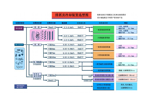
链板排屑器链板式排屑器主要用于收集和输送各种材质的卷状、团状、条状、块状切屑。
广泛应用于各类数控机床、加工中心和柔性生产线,它在机床领域中使用最广泛的一种排屑装置,该设备起到改善操作环境,减轻劳动强度,提高整机自动化程度的作用。
产品性能、特点:1.本产品采用沈阳机床专利技术——复合链板、刮板排屑结构,可自动清理积存在排屑器主体内切屑;2.链板采用优质不锈钢板铰接,表面冲压凸点,细小切屑不易粘附;3.主要零部件均经过耐磨及耐腐蚀处理;4.排屑器传动轴设有摩擦片离合器可实现过载保护,碟型弹簧、双螺纹锁进结构可保证排屑器具有较大的输出扭矩。
技术支持:1.排屑器的外形尺寸非常重要,它不仅要保证与机床有机联接,还要充分考虑排屑器内部结构制造,切屑的流动方向和所受阻力,以保证排屑器具有较大的承载能力和较高的可靠性。
排屑器入口有效容屑深度尺寸E:在机床允许的范围内,尽可能大一些,排屑器排屑通道高度尺寸F:要大于E+(50~100);排屑出口C尺寸:一般选择要大于300 ~400;大型排屑器可以选择更大。
排屑器与水箱联接的极限组合尺寸B3>20mm2.建议各主机技术部在机床总体设计时,根据用户的使用需求,尽可能的考虑机床切屑、冷却液的排出量,综合机床总体布局,较合理的确定排屑器的外形尺寸和电机功率、冷却泵参数及排屑量;3.表中的各种参数,可作为参考,由于链板排屑器的制造所受约束条件较少,设计者可在上表的“主机设计给定”处,根据机床需要进行变换,其中β角度可选择常用角度,必要时,可选择00,即直排式;4.链板排屑器一般都具有排水装置,在机床总图布置时,请注明冷却水的过滤路径和冷却循环的出口压力及流量参数;5.请注明排屑器的属性,如:电源的电压、频率;是否具有CE防护要求等;6.在排屑器方案设计时,可通知我们共同研究、操作。
刮板排屑器及磁性刮板排屑器刮板排屑装置主要用于短屑及碎屑的连续输送,不受切屑材质限制的优点。
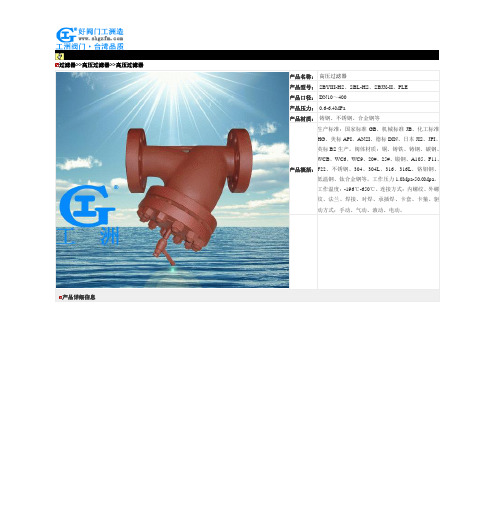
高压过滤器-SBYIII-HS、SBL-HS、SBJX-II、PLE高压过滤器
过滤器>>高压过滤器>>高压过滤器产品详细信息过滤器系列价格供用户或设计院工程项目做预算一、阀门的选型步骤1.明确阀门在设备或装置中的用途,确定阀门的工作条件:适用介质、工作压力、工作温度等等。
2.确定与阀门连接管道的公称通径和连接方式:法兰、螺纹、焊接等。
3.确定操作阀门的方式:手动、电动、电磁、气动或液动、电气联动或电液联动等。
4.根据管线输送的介质、工作压力、工作温度确定所选阀门的壳体和内件的材料:灰铸铁、可锻铸铁、球墨铸铁、碳素钢、合金钢、不锈耐酸钢、铜合金等。
5.确定阀门的型式:闸阀、截止阀、球阀、蝶阀、节流阀、安全阀、减压阀、蒸汽疏水阀、等。
6.确定阀门的参数:对于自动阀门,根据不同需要先确定允许流阻、排放能力、背压等,再确定管道的公称通径和阀座孔的直径。
7.确定所选用阀门的几何参数:结构长度、法兰连接形式及尺寸、开启和关闭后阀门高度方向的尺寸、连接的螺栓孔尺寸和数量、整个阀门外型尺寸等。
8.利用现有的资料:阀门产品目录、阀门产品样本等选型适当的阀门产品。
二、阀门的选型依据1.所选用阀门的用途、使用工况条件和操纵控制方式。
2.工作介质的性质:工作压力、工作温度、腐蚀性能,是否含有固体颗粒,介质是否有毒,是否是易燃、易爆介质,介质的黏度等等。
3.对阀门流体特性的要求:流阻、排放能力、流量特性、密封等级等等。
4.安装尺寸和外形尺寸要求:公称通径、与管道的连接方式和连接尺寸、外形尺寸或重量限制等。
⑤对阀门产品的可靠性、使用寿命和电动装置的防爆性能等的附加要求。
(在选定参数时应注意:如果阀门要用于控制目的,必须确定如下额外参数:操作方法、最大和最小流量要求、正常流动的压力降、关闭时的压力降、阀门的最大和最小进口压力。
)根据上述选型阀门的依据和步骤,合理、正确地选型阀门时还必须对各种类型阀门的内部结构进行详细了解,以便能对优先选用的阀门做出正确的抉择。
管道的最终控制是阀门。
黎明滤芯型号大全

国产化滤芯黎明液压滤芯:LH0060D3BN/HC、LH0060D5BN/HC、LH0060D10BN/HC、LH0060D20BN/HC,LH0110D3BN/HC、LH0110D5BN/HC、LH0110D10BN/HC、LH0110D20BN/HC,LH0160D3BN/HC、LH0160D5BN/HC、LH0160D10BN/HC、LH0160D20BN/HC,LH0240D3BN/HC、LH0240D5BN/HC、LH0240D10BN/HC、LH0240D20BN/HC,LH0330D3BN/HC、LH0330D5BN/HC、LH0330D10BN/HC、LH0330D20BN/HC,LH0500D3BN/HC、LH0500D5BN/HC、LH0500D10BN/HC、LH0500D20BN/HC,LH0660D3BN/HC、LH0660D5BN/HC、LH0660D10BN/HC、LH0660D20BN/HC,LH0060R1BN/HC、LH0060R3BN/HC、LH0060R5BN/HC、LH0060R10BN/HC、LH0060R20BN/HC、LH0060R30BN/HC,LH0110R1BN/HC、LH0110R3BN/HC、LH0110R5BN/HC、LH0110R10BN/HC、LH0110R20BN/HC、LH0110R30BN/HC,LH0160R1BN/HC、LH0160R3BN/HC、LH0160R5BN/HC、LH0160R10BN/HC、LH0160R20BN/HC、LH0160R30BN/HC,LH0240R1BN/HC、LH0240R3BN/HC、LH0240R5BN/HC、LH0240R10BN/HC、LH0240R20BN/HC、LH0240R30BN/HC,LH0330R1BN/HC、LH0330R3BN/HC、LH0330R5BN/HC、LH0330R10BN/HC、LH0330R20BN/HC、LH0330R30BN/HC,LH0500R1BN/HC、LH0500R3BN/HC、LH0500R5BN/HC、LH0500R10BN/HC、LH0500R20BN/HC、LH0500R30BN/HC,LH0660R1BN/HC、LH0660R3BN/HC、LH0660R5BN/HC、LH0660R10BN/HC、LH0660R20BN/HC、LH0660R30BN/HC,LH0850R1BN/HC、LH0850R3BN/HC、LH0850R5BN/HC、LH0850R10BN/HC、LH0850R20BN/HC、LH0850R30BN/HC,LH0950R1BN/HC、LH0950R3BN/HC、LH0950R5BN/HC、LH0950R10BN/HC、LH0950R20BN/HC、LH0950R30BN/HC,LH1300R1BN/HC、LH1300R3BN/HC、LH1300R5BN/HC、LH1300R10BN/HC、LH1300R20BN/HC、LH1300R30BN/HC
液压油滤油机
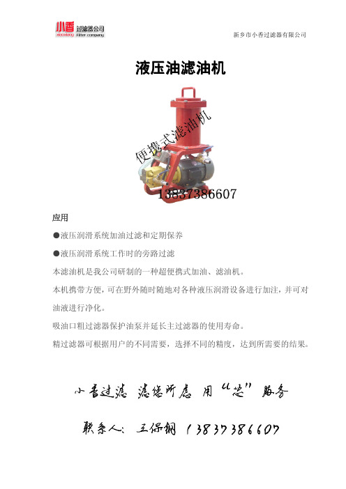
滤油机液压油滤油机液压油应用●液压润滑系统加油过滤和定期保养●液压润滑系统工作时的旁路过滤本滤油机是我公司研制的一种超便携式加油、滤油机。
本机携带方便,可在野外随时随地对各种液压润滑设备进行加注,并可对油液进行净化。
吸油口粗过滤器保护油泵并延长主过滤器的使用寿命。
精过滤器可根据用户的不同需要,选择不同的精度,达到所需要的结果。
外形尺寸:系统原理图:技术参数:注:*为精过滤器的精度,如003为3微米**为所适用的介质,省略:一般液压油;BH:水—乙二醇V:膦酸酯液压液**适应介质粘度≤160cSt定做各种滤油机滤芯新乡市小香过滤器有限公司一、公司简介新乡市小香过滤器有限公司,是一家集科研、生产.销售、服务为一体的大型股份制企业,坐落于豫北地区最大的滤芯、滤清器生产基地新乡市经济技术开发区,占地面积300亩,是新乡市人民政府规划定点的过滤与分离行业专业园区。
我公司主要从事液压油过滤与分离技术研究,并与各大设计研究院以及大专院校建立了兄弟般的全面合作关系,专业生产液压油过滤器、滤芯、滤油机、除尘净化滤芯、滤清器、检测设备及液压元件等,产品达上万种。
公司已全面通过ISO9001:2002国际质量管理体系认证。
经过多年的努力,凭借公司过硬的质量和良好的信誉,公司已在国内与众多生产厂家建立了长期、稳定的供货关系,这些行业涵盖了炼钢、炼铁、工程机械、彩管、舰船制造业、坦克、装甲车、纺织、冰箱、空调、汽车制造、摩托车制造、发电、煤矿、石化、制药、重型机械、卷烟、化肥等众多的行业。
目前我们已与中国最大的造纸企业—玖龙纸业、中国最大的风能电力系统公司—维斯塔斯风力系统(中国)有限公司、斯凯孚集团的合资子公司中国SKF铁路轴承有限公司、三一重工集团有限公司、天钢、柳钢、湖南涟钢、安阳钢铁、九江发电厂,龙潭发电厂,天津国电、航空部国营第134厂、中国船舶重工集团公司、长春新大石油集团、神华集团等建立了牢固的业务关系,对钢铁行业的过滤系统、过滤器及滤芯有充分的了解和完善的技术资料。
黎明滤芯型号

GX-100×*GX-160×*GX-250x*GX-400×*GX-630×*(*分别代表3,5,10,20,30,40)ISV系列管路吸油过滤器滤芯型号:IX-40×*IX-63×*IX-100×*IX-160×*IX-250×*IX-400×*IX-630×*IX-800×*IX-1000×*(*分别代表80,100,180)ZU-A,QU-A,WU-A系列回油过滤器滤芯型号:TZX2-10×*TZX2-25×10TZX2-40×10、TZX2-63×10、TZX2-100×10TZX2-160×*TZX2-250×*TZX2-400×*TZX2-630×*TZX2-800×*TZX2-1000×*(*分别代表1,3,5,10,20,30)XU-A系列回油过滤器滤芯型号:TXX-25×*TXX-40×*TXX-63×*TXX-100×*TXX-160X*TXX-250×*TXX-400×*TXX-630×*(*分别代表30,50)GP系列磁性回油过滤器滤芯型号:GP300×*Q2GP400×*Q2GP500×*Q2GP600×*Q2(*分别代表3,5,10,20,30)WY系列磁性回油过滤器滤芯型号:WY300×*Q2WY400×*Q2WY500×*Q2WY600×*Q2WY700×*Q2WY800×*Q2(*分别代表3,5,10,20,30)TF系列箱外自封式吸油过滤器滤芯型号:TFX-25×*TFX-40×*TFX-63×*TFX-100×* TFX-160×*TFX-250×*TFX-400×*TFX-630×*TFX-800×*TFX-1000×*TFX-1300×*(*分别代表80,100,180)自封式磁性吸油过滤器滤芯型号:FX-510X*FX-515X*FX-520X*(*分别代表80,100,180)ZL12-122自封式磁性吸油过滤器滤芯型号:ZL12X-122/*ZL12BX-122/*(*分别代表10,25,80)QYL型回油过滤器滤芯型号:QYLX-63×*Q2QYLX-100×*Q2QYLX-160×*Q2 QYLX-250×*Q2QYLX-400×*Q2(*分别代表3,5,10,20,30)TFB系列吸油过滤器滤芯型号:TFBX-45×*TFBX-70×*(*分别代表10,20,30,80)XNL系列箱内回油过滤器滤芯型号:NLX-25×*NLX-40×*NLX-63×*NLX-100×* NLX-160×NLX-250×*NLX-400×*NLX-630×*NLX-800×*NLX-1000×*(*分别代表3,5,10,20,30)旋装式管路过滤器滤芯型号:SPX-06×10,SPX-06X25,SPX-08×10、SPX-08×25、SPX-10×10、SPX-10×25、SPAX-10×10HX-10×*Q HX-10×*W HX-25×*HX-25×*Q HX-25×*W HX-63×*HX-63×*Q HX-63×*WHX-100×*HX-100×*Q HX-100×*W HX-160×*HX-160×*Q HX-160×*W HX-250×*HX-250×*Q HX-250×*W HX-400×*HX-400×*Q HX-400×*W HX-630×*HX-630×*QHX-630×*W HX-800×*HX-800×*Q HX-800×*W HBX-10×*HBX-25×*HBX-40×*HBX-63×*HBX-110×*HBX-160×*HBX-250×*HBX-400×*HBX-630×*HDX-10×*HDX-25×*HDX-40×*HDX-63×*HDX-100×*HDX-160×*HDX-250×*HDX-400×*HDX-630×*(*分别代表1,3,5,10,20,30,40)XU-A系列回油过滤器滤芯型号:TXX-25×*TXX-40×*TXX-63×*TXX-100×*TXX-160X*TXX-250×*TXX-400×*TXX-630×*(*分别代表30,50)RFA系列微型直回式回油过滤器滤芯型号:FAX-25×*FAX-40×*FAX-63×*FAX-160×*FAX-250×*FAX-400×*FAX-630×*FAX-800×*FAX-1000×*(*分别代表1,3,5,10,20,30)RFB系列直回自封式磁性回油过滤器滤芯型号:FBX-25×*FBX-40×*FBX-63×* FBX-100×*FBX-160×*FBX-250×*FBX-400×*FBX-630×*FBX-800×*FBX-1000×*FBX-1300×*(*分别代表1,3,5,10,20,30)SRFA系列双筒微型直回式回油过滤器滤芯型号:SFAX-25×*SFAX-40×*SFAX-63×* SFAX-100×*SFAX-160×*SFAX-250×*SFAX-400×*SFAX-630×*SFAX-800×*(*分别代表1,3,5,10,20,30)SRFB系列双筒直回式回油过滤器滤芯型号:SFBX-25×*SFBX-40×*SFBX-63×* SFBX-100×*SFBX-160×*SFBX-250×*SFBX-400×*SFBX-630×*SFBX-800×*SFBX-1000×*SFBX-1300×*(*分别代表1,3,5,10,20,30)SRLF系列双筒回油管路过滤器滤芯型号:SFX-60×*SFX-110×*SFX-160×*SFX-240×*SFX-330×*SFX-500×*SFX-660×*SFX-850×*SFX-950×*SFX-1300×*(*分别代表1,3,5,10,20,30,40)SZU-A,SQU-A,SWU-A,SXU-A系列双筒回油过滤器滤芯型号:STZX2-25×* STZX2-40×*STZX2-63×*STZX2-100×*STZX2-160×*STZX2-250×*STZX2-400×*(*分别代表1,3,5,10,20,30,40)SXU-A系列双筒回油过滤器滤芯型号:STXX-25×*STXX-40×*STXX-63×*STXX-100×*STXX-160×*STXX-250×*STXX-400×*(*分别代表30,50)SGF系列双筒高压过滤器滤芯型号:PLFX-30×*(*分别代表3,5,10,20)。
XU-A、B两系列线隙式过滤器---克瑞斯过滤提供参考

XU-A25×※-P XU-A25×※BP SDRLF-A1300×※PXU-A40×※-P XU-A40×※BP SDRLF-A2600×※PXU-A63×※-P XU-A63×※BP SDRLF-A3900×※PXU-A100×※-P XU-A100×※BP SDRLF-A6500×※PXU-A160×※-P XU-A160×※BP SDRLF-A7800×※PXU-A250×※-P XU-A250×※BP SDRLF-A9100×※PXU-A400×※-P XU-A400×※BPXU-A630×※-P XU-A630×※BPSRFB(SPZU)双筒回油过滤器10~30μCWU 磁性过滤器SRFA(SLHN)双筒回油过滤器10~30μ克瑞斯过滤技术CWU-10×100B SRFA-25×※LY/C SRFB-25×※FY/CCWU-A25×60SRFA-40×※LY/C SRFB-40×※FY/CCGQ系列强磁管路过滤器SRFA-63×※LY/C SRFB-63×※FY/CCGQ-6SRFA-100×※LY/C SRFB-100×※FY/CCGQ-8SRFA-160×※LY/C SRFB-160×※FY/CCGQ-10SRFA-250×※LY/C SRFB-250×※FY/CCGQ-12SRFA-400×※LY/C SRFB-400×※FY/CCGQ-15SRFA-630×※LY/C SRFB-630×※FY/CCGQ-20SRFA-800×※LY/C SRFB-800×※FY/CCGQ-25SRFA-1000×※LY/C SRFB-1000×※FY/CCGQ-32新乡克瑞斯提供参考!!SRFB-1300×※FY/CCGQ-40SZU 双筒管路过滤器10~30μvCGQ-50SZU-A25×※PSRLF双筒回油过滤器10~30μSXU 双筒管路过滤器30~50μSZU-A40×※PSRLF-60×※F-P SXU-A25×※P SZU-A63×※PSRLF-110×※F-P SXU-A40×※P SZU-A100×※PSRLF-160×※F-P SXU-A63×※P SZU-A160×※PSRLF-240×※F-P SXU-A100×※P SZU-A250×※PSRLF-330×※F-P SXU-A160×※P SZU-A400×※PSQU-A400×※P SLLF双筒润滑过滤器80~120μSMF 双筒高压过滤器SGF双筒高压过滤器10~20μSLLF-32×※P SMF-D30×※CSGF-H30×※C SLLF-40×※P SMF-D100×※CSGF-H60×※C SLLF-50×※P C型系列空气过滤器SGF-H110×※C SLLF-65×※PSGF-H160×※C SLLF-80×※PSGF-H240×※C SLLF-100×※PSGF-H330×※C SLLF-150×※PSGF-H500×※C SLLF-200×※PSGF-H660×※C咨询0373*******XU-A25×※-P XU-A25×※BP SDRLF-A1300×※P XU-A40×※-P XU-A40×※BP SDRLF-A2600×※P XU-A63×※-P XU-A63×※BP SDRLF-A3900×※P XU-A100×※-P XU-A100×※BP SDRLF-A6500×※P XU-A160×※-P XU-A160×※BP SDRLF-A7800×※P XU-A250×※-P XU-A250×※BP SDRLF-A9100×※P XU-A400×※-P XU-A400×※BPXU-A630×※-P XU-A630×※BPCWU 磁性过滤器SRFA(SLHN)双筒回油过滤器10~30μSRFB(SPZU)双筒回油过滤器10~30μCWU-10×100B SRFA-25×※LY/C SRFB-25×※FY/CCWU-A25×60SRFA-40×※LY/C SRFB-40×※FY/CCGQ系列强磁管路过滤器SRFA-63×※LY/C SRFB-63×※FY/CCGQ-6SRFA-100×※LY/C SRFB-100×※FY/CCGQ-8SRFA-160×※LY/C SRFB-160×※FY/CCGQ-10SRFA-250×※LY/C SRFB-250×※FY/CCGQ-12SRFA-400×※LY/C SRFB-400×※FY/CCGQ-15SRFA-630×※LY/C SRFB-630×※FY/CCGQ-20SRFA-800×※LY/C SRFB-800×※FY/CCGQ-25SRFA-1000×※LY/C SRFB-1000×※FY/CCGQ-32SRFB-1300×※FY/CCGQ-40克瑞斯过滤技术提供参考!!SZU 双筒管路过滤器10~30μvCGQ-50SZU-A25×※PSRLF双筒回油过滤器10~30μSXU 双筒管路过滤器30~50μSZU-A40×※PSRLF-60×※F-P SXU-A25×※P SZU-A63×※PSRLF-110×※F-P SXU-A40×※P SZU-A100×※PSRLF-160×※F-P SXU-A63×※P SZU-A160×※PSRLF-240×※F-P SXU-A100×※P SZU-A250×※PSRLF-330×※F-P SXU-A160×※P SZU-A400×※PSQU-A400×※P SLLF双筒润滑过滤器80~120μSMF 双筒高压过滤器SGF双筒高压过滤器10~20μSLLF-32×※P SMF-D30×※CSGF-H30×※C SLLF-40×※P SMF-D100×※CSGF-H60×※C SLLF-50×※P C型系列空气过滤器SGF-H110×※C SLLF-65×※PSGF-H160×※C SLLF-80×※PSGF-H240×※C SLLF-100×※PSGF-H330×※C SLLF-150×※PSGF-H500×※C SLLF-200×※PSGF-H660×※C。
FGG系列过滤器操作手册说明书

OPERATION MANUALSMC Filter (FGG series)FGG □□-20-※A-□SMC CorporationINDEX● Safety Instruction ・・・・・・・・・・・・・P2、3 ● Construction ・・・・・・・・・・・・・・・・P4 ● Specification ・・・・・・・・・・・・・・・・P5 ● Installation / Piping ・・・・・・・・・・・・P5 ● Operation ・・・・・・・・・・・・・・・・・P5● Replacement of the element ・・・・・・P6、7Select optionSelect elementElement lengthFGG Series/ Safety InstructionBe sure to read before handling.These safety instructions are intended to prevent a hazardous situation and/or damage to human and equipment by using FGG series properly.Incorrect handling lead to cause fluid leakage or displacement Of the cover which result in unexpected accident..Compatibility of the equipment shall be judged by system designers with knowledge and experience.Cautions shall be followed to avoid element damageand ensure the performance and maintainability.Operating condition rangeDesign and installationWarning① Operating pressure・Do not use pressure exceeding specified range. ② Operating temperature・Do not use where temperature exceeding specified range.③ Operating fluid・Do not use this for gases.・Do not use with corrosive fluid.・Do not use fluid which swell or deteriorates packing, “O” ring or element. ④ Operating environment・Do not use in corrosive environment.・Do not use where exposed to vibration or impact.Caution on operationWarning① Do not loosen V band while pressure is applied.② Install V band correctly to specified position. (See page 7)③ Replace deteriorated or swollen “O” ring.Replace “O” ring in one year after starting use, or fluid leakage occurs.(See page 4 Table 1 :“O” ring for replacement) ④ When supplying pressure for starting the pump,open the relief port to discharge air.⑤ Do not use V band which is deformed or thread is grounded.(See page 4 table 1 : V band for replacement)Warning① Design the system which operating conditionsincluding operating pressure, operating temp., operating fluid, and operating environment shall be appropriate safe operation. ② Pressure drop (ΔP)・Set the flow so that the initial pressure drop is 0.02MPa or less. ③ Space to install・Reserve maintenance space for installation and piping. ④ Flusing・Flush piping line with air before the first usage. ⑤ Prepare air discharge circuit upon necessity.⑥ For high temp. type, protection against burning shall be prepared.⑦ Prepare drain or the circuit to discharge fluid upon necessity.⑧ Use the filter with circuit in which changing loadof the pressure and the flow is small.FGG Series/Safety InstructionBe sure to read before handling.These safety instructions are intended to prevent a hazardous situation and/or damage to human and equipment by using FGG series properly.Maintenance Piping and operation Caution① Foreign matters shall be discharged from drainoutlet.② Replacement of the elementWhen it is the time for replacement of the element,replace with a new element immediately.・The life of element-・ When pressure drop reaches 0.1MPa, replace theelement referring the procedure in this manual.Incorrect handling causes the damage of equipmentand device, and the operation failure.(See Page 6,7 : Replacement of element)③ Cleaning of equipmentWhen replacing the element, clean “O” ting, packingseat surface, the joint part of V band, and thread forsealing properly.④ Surface temp.Confirm that the surface temp. is 40oC or lower whenreplacing the element. For high temp. use, attentionshould be taken to avoid burning.Caution① Ensure the direction of IN/OUT for piping.②Arrange piping so that air discharging work isavailable.③Check each port size for selecting valves andfitting suitable for operating conditions. Flushpiping line with air before operation to check anyproblem including fluid leakage.④Fix the feet to the ground firmly using foundationbolt(M12).⑤ The piping of INLET and OUTLET shall be fixedfirmly to the mounting frame using the saddle sothat load including vibration or weight is notapplied to the piping.⑥ When supplying pressure for starting the pump,ensure opening/closing of piping and connectingparts are completely sealed. If fluid leakage ispresent, stop operation immediately. Investigatethe cause, and replace “O” ring to a new one.Then, tighten the fitting and perform anycorrective action for fluid leakage before restartingoperation.⑦ When supplying pressure for starting the pump,open the relief port(hexagon plug) to discharge air.Release the air(loosen the hex. plug) at the sametime supplying the fluid to substitute air in theproduct by fluid. When air is discharged, close therelief port(tighten the hex. plug) before startingoperation.1. ConstructionFig. 1 Description of parts and functionsTable 1. Description and function of partsNo Description Part number Material Function① Hex. Plug AG-10SSUS304 Plug to release air in the housingJIS B2401-1A-P11 NBR ② “O” ring JIS B2401-4D-P11 FKM “O”ring to seal the cover and hex. plug ③ Wing nut M10×1.5 Class 1SUS304 ④ Washer M10 SUS304 Fix the element retainer⑤ Element retainer- SUS304 Fix the element⑥ Spring AN-3S SUS316WPA Stabilizes the element seal ⑦ Element holder L-27SSUS316 Seals the element ⑧ Element guide U-8S、U-9S、U-10SSUS304 Guides the element ⑨ Tension bolt - SUS304 Shaft fix the element⑩ Element - - Assemble elements into this ⑪ JointJ-4S SUS316 Seal the space between elementAL-25S NBR ⑫ “O” ring AL-22SFKM “O”ring used to seal the sealing part of the cover and the case⑬ V band CY-27S SUS304/SWCH Engage the cover and the case and settle Them⑭ Cover - SUS304 The lid of the product ⑮ Case - SUS304 Main body of the case⑯ Foot- SS400 Support the body(Fix to the ground)⑰ Description on label BH-73S Tetlon ⑱Caution labelBH-77STetlonCautionWhen becomes dirty,replace with anew one(Port size : R2pump.(Port size : G1/8replacing the element.(Port size : R3/4) E N T2. Specifications3. Installation / Piping1)Installation・Fix the feet to the ground firmly using foundation bolt(M12).・Install and arrange piping at the place with enough space for maintenance.2)Piping・Check connect port size to use valves and fitting suitable for operating conditions.・Arrange the piping so that pressure in the product can be released.※Confirm cautions on page 2 and 3 for use.4. Operation1)Operation・Mount V band to specified position. Confirm connecting parts and seal do not leak before start operation.・When starting operation, open upper relief port(loosen hex. plug) to discharge air.2)Replacing the element・Replace the element when pressure drop become lower than specification value.For the replacement of the element, see Replacement of the element on page 6.※Confirm cautions on page 2 and 3 for use.2①Remove the wing nut and the washer.Caution②Remove the element retainer.③Remove the element mount bracket(a part integrating the element holder and the spring).④Take out parts in order of the element, then, joint(element guide).※Caution3① To recycle the micro mesh element and sintered element, eliminate any dust between the end plate and the packing completely.②Mount the element guide if it is removed.③Insert parts in order of the element, joint , element, then, element mount bracket so that they are concentric.Caution④When 2 to 3 elements are placed on top of the other, a set in which the element and joint are prepared can be mounted to the element⑤Assemble the element mount bracket.⑥Mount the element retainer carefully.(1)×Fig. (b)①Mount V band to the collar of the cover and the case correctly. [Refer Fig. (a), (b)Warning②Hit the circumference of V band lightly with plastic hammer for secure mounting.③Mount T bracket to the latch correctly. [See Fig. (c)]④Tighten the clamping nut to specified nut(position from whereinsert the clamping position check pin. [See Fig.(c)]⑤When tightening nut can not be tightened to specified position(position where clamping position check pin can be inserted), replace V band and O ring to new ones. (See table 1).CautionWarningURL Akihabara UDX 15F,4-14-1, Sotokanda, Chiyoda-ku, Tokyo 101-0021,JAPANPhone: +81 3 5207 8249 Fax: +81 3 5298 5362Specifications are subject to change without prior notice and any obligation the part of 2008 SMC Corporation All Rights Reserved。
富士工业-FGE系列过滤器-使用说明书

工業用过滤器FGE 系列FGES□-□-□A-□ FGEL□-□-□A-□滤芯长度连接口径可选项滤芯分类SL安全注意事项・・・・・・・・・・・・・・・・・・・・・・・・・・・・・・・・・・ 3 FGES・L个别注意事项 ・・・・・・・・・・・・・・・・・・・・・・・・・・・・・・ 5 各部分的名称及功能 ・・・・・・・・・・・・・・・・・・・・・・・・・・・・・・・ 7 产品规格・・・・・・・・・・・・・・・・・・・・・・・・・・・・・・・・・・・・・8 安装・配管・・・・・・・・・・・・・・・・・・・・・・・・・・・・・・・・・・・8 操作 ・・・・・・・・・・・・・・・・・・・・・・・・・・・・・・・・・・・・・・ 9 滤芯更换方法・・・・・・・・・・・・・・・・・・・・・・・・・・・・・・・・・・ 10安全注意事项此处所示的注意事项是为了确保您能安全正确地使用本产品,预先防止对您和他人造成危害和损失而制定的。
这些注意事项,按照危害和损伤的大小及紧急程度分为「注意」「警告」「危险」三个等级。
无论哪项都是与安全相关的重要内容,所以除了遵守国际规格(ISO/IEC)、日本工业规格(JIS) ※1)以及其他安全法规 ※2)外,这些内容也请务必遵守。
※1) ISO 4414: Pneumatic fluid power -- General rules relating to systemsISO 4413: Hydraulic fluid power -- General rules relating to systemsIEC 60204-1: Safety of machinery -- Electrical equipment of machines (Part 1: General requirements) ISO 10218-1992: Manipulating industrial robots-SafetyJIS B 8370: 空气压系统通则JIS B 8361: 油压系统通则JIS B 9960-1: 机械类的安全性、机械的电气装置(第1部: 一般要求事项)JIS B 8433-1993: 产业用操作机器人-安全性等※2) 劳动安全卫生法等注意 误操作时,有人员受伤的风险,以及物品破损的风险。警告 误操作时,有人员受到重大伤害甚至死亡的风险。
黎明液压- SMF系列双筒中压过滤器
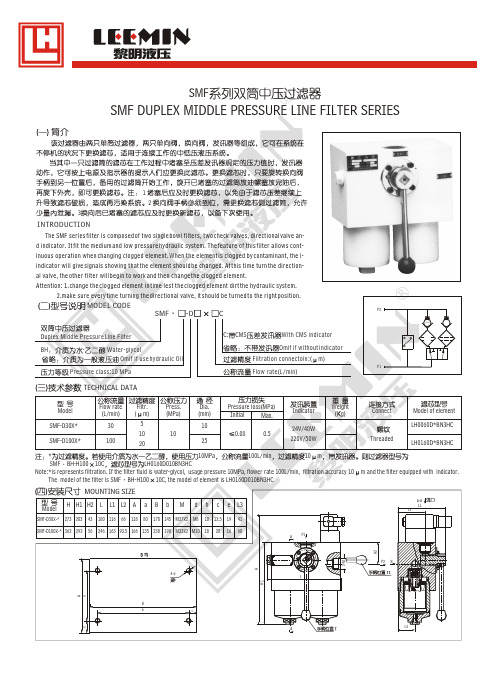
10 12.5 19 20 16
SMF-D100X-* 362 292
246 163 93.5 166 135 230 190 M33X2 M10 18
H2
2-M
P2
B
A a
B b
c
H1
4-d h
H
L
AБайду номын сангаас
L3
e
* 10MPa 100L/min 10 m SMF BH-H100 10C LH0160D010BN3HC Note:*is represents filtration. If the filter fluid is water-glycol, usage pressure 10MPa, flower rate 100L/min, filtration accuracy 10 The model of the filter is SMF BH-H100 10C, the model of element is LH0160D010BN3HC
m and the filter equipped with indicator.
MOUNTING SIZE
Model
SMF-D30X-*
H H1 H2 L
273 203 43 56
L1 L2 A
66 118
a
80
B
b
M
d
h
c
e
L3
41 60
A
P1
L2
A-A L1
180 116
170 145 M27X2 M8
SMF
SMF DUPLEX MIDDLE PRESSURE LINE FILTER SERIES
1 2 3
SGT6-5000F型燃气轮机压气机滤网压差高的原因及应对措施
SGT6-5000F型燃气轮机压气机滤网压差高的原因及应对措施发布时间:2022-09-13T03:58:08.223Z 来源:《当代电力文化》2022年第9期作者:巩凤祥刘剑[导读] 燃气轮机是发电厂供电的重要设备,其压气机做功性能的好坏,直接关系着发电厂供电效率的高低。
巩凤祥刘剑青岛华丰伟业电力科技工程有限公司山东青岛 266100摘要:燃气轮机是发电厂供电的重要设备,其压气机做功性能的好坏,直接关系着发电厂供电效率的高低。
影响压气机做功性能的主要因素之一,是吸入空气的质量与温度等特征,这是因为空气中还有杂质常常会造成压气机滤网压差高,从而对压气机做功性能造成影响。
本文以SGT6-5000F型燃气轮机为例,对压气机滤网压差高的原因进行分析,并针对性地提出应对措施,用来预防和解决压气机滤网压差高的问题,从而确保燃气轮机在发电厂供电工作中发挥应有的作用。
关键词:压气机系统;滤网;压差高;应对策略;SGT6-5000F型燃气轮机引言燃气轮机是发电厂供电的重要设备,其压气机做功性能的好坏,直接关系着发电厂供电效率。
压气机进气系统吸入空气的质量与温湿度,是影响压气机做功性能的主要因素之一,这是因为空气中的灰尘、颗粒物等杂质常常会附着在滤网上面堵塞滤网,影响空气的吸入,从而造成压气机滤网压差升高,致使压气机做功性能降低。
1.SGT6-5000F型燃气轮机压气机系统介绍西门子公司出产的SGT6-5000F型燃气轮机,是由一个13级的高效率轴流式压气机、一个由16个燃烧器组成的环形燃烧系统、一个4级透平转子组成。
轴流式压气机转子和透平转子由中空的扭矩管连接,双轴承支撑,冷端驱动。
燃机压气机进气系统包括进气口滤清器室、进风道和消音器系统、脉冲进气口过滤系统、滤清器等,其具体组成如下:1)进气口滤清器室(1)过滤系统由防雨罩、防鸟窗、自清洁过滤器系统等组成。
(2)进气脉冲过滤器由垂直的脉冲过滤模块构成。
过滤元件为自清洁型,通过一个脉冲系统,在过滤元件内部发岀瞬间脉冲气流,撞掉堆积在过滤元件上的灰尘和污垢,并将其吹离过滤元件。
- 1、下载文档前请自行甄别文档内容的完整性,平台不提供额外的编辑、内容补充、找答案等附加服务。
- 2、"仅部分预览"的文档,不可在线预览部分如存在完整性等问题,可反馈申请退款(可完整预览的文档不适用该条件!)。
- 3、如文档侵犯您的权益,请联系客服反馈,我们会尽快为您处理(人工客服工作时间:9:00-18:30)。
be changed in time until the pressure reaches to 0.6Mpa, the by-pass valve will
( )
MODEL CODE
67
SGF -H Press. (MPa) Dia. (mm) 20 20 20 32 32 32 50 50 50
INTRODUCTION
15
TECHNICAL DATA
Flow rate (L/min) 30 60 110 160 240 330 500 660 10 20 3 5
Model
Filtr. ( m)
Pressure loss(MPa) Initial Max.
SGF-H30 * SGF-H60 *
H
4
新乡市小香过滤器有限公司
( ) MOUNTING SIZE
H1 D A L L1 L4
91
2-DN 6-M
01
L5 B2 B4 B1 P2 B3 B6 P1 B5 B3 B
13 15
67
2-d1 4-d L3 L2
4
Unit:mm H SGF-H30 * SGF-H60 * SGF-H110 * SGF-H160 * SGF-H240 * SGF-H330 * SGF-H500 * SGF-H660 * 180 196 265 251 309 330 423 497 H1 106 106 106 129 129 152 152 152 B 242 242 242 278 278 377 377 377 B1 136 136 136 172 172 230 230 230 B2 106 106 106 142 142 190 190 190 B3 32 32 32 45 45 57 57 57 B4 36 36 36 48 48 66 66 66 B5 28 28 28 29 29 41 41 41 B6 30 30 30 30 30 48 48 48 A 120 120 120 140 140 210 210 210 L 246 246 246 296 296 414 414 414 L1 210 210 210 260 260 380 380 380 L2 104 104 104 110 110 160 160 160 L3 46 46 46 52 52 85 85 85 L4 134 134 134 140 140 200 200 200 L5 44 44 44 44 44 60 60 60 D 73 73 73 102 102 146 146 146 DN 20 20 20 32 32 50 50 50 1 d 28 28 28 40 40 60 60 60 d 17.5 17.5 17.5 17.5 17.5 26 26 26 M M12 M12 M12 M12 M12 M20 M20 M20
SGF-H110 * SGF-H160 * SGF-H240 * SGF-H330 * SGF-H500 * SGF-H660 *
* 32MPa 160L/min 10 m SGF BH-H160 10C LH0160D010BN3HC Note:*is represents filtration. If the filter fluid is water-glycol, usage pressure 32MPa flower rate 160L/min filtration accuracy 10 tor. The model of the filter is SGF BH-H160 10C, the model of element is LH0160D010BN3HC
Water-glycol Omif if use hydraulic oil
Duplex high pressure line filter
01
P2
Indicator (V) 12 24 0.08 0.5 36 220 1.5 0.25 Flange (A) 2.5 2 Weight (Kg) Connect Model of element PLFX-30 * LH0060D*BN3HC LH0110D*BN3HC LH0160D*BN3HC LH0240D*BN3HC LH0330D*BN3HC LH0500D*BN3HC LH0660D*BN3HC m and the filter equipped with indica-
91
C: CMS : F: With CMS indicator Omit if without indicator Flanged connection Filtrati/min)
P1
BH: :
Pressure class:32MPa
13
新乡市小香过滤器有限公司
SGF
SGF DUPLEX HIGH PRESSURE LINE FILTER SERIES
0.5MPa
0.6MPa
The SGF series filter is composed of two single bowl filters, check valve, di-
rectional valve and indicator. It should be installed at outlet of the high-pressure line. The feature of this filter allows continuous operation even during replacing element, which is clogged by contaminant. When the pressure of the contaminant clogged element reaches to 0.5Mpa, the indicator gives signals showing that the element should be changed. At this time, turn the directional valve, let the other filter work, and change the clogged element. If the element can't open automatically to keep the system safety.
