ADS教程第11章
集智(ADS)桌面云管理系统-说明书

桌面云管理系统-说明书目录前言.................................................................................................... 错误!未定义书签。
第一章:软件概述 .. (4)1、软件说明 (4)2、系统结构 (4)3、系统特点 (4)4、主要功能 (4)5、应用领域 (5)6、术语解释 .................................................................................. 错误!未定义书签。
第二章:系统安装说明 . (5)1、系统安装环境 (5)2、网络环境要求 ........................................................................... 错误!未定义书签。
3、安装流程图............................................................................... 错误!未定义书签。
第三章:服务器安装............................................................................. 错误!未定义书签。
1、快速安装指南 ........................................................................... 错误!未定义书签。
2、安装服务器操作系统................................................................. 错误!未定义书签。
3、ADS 服务端安装与配置 ............................................................ 错误!未定义书签。
ADS新手使用教程

ADS使用例程前言:ADS是一个开发ARM很好的环境,同样周立功单片机()推出的EasyARM2104实验套件也是学习ARM相当超值的入门工具。
由于配套实验书上对于如何做第一个实验方面给出的指导具体步骤不够清晰,新手一般都要摸索一阵子,所以本人写了如下一个ADS的使用例程,演示一个最简单的程序的运行范例。
另外,ADS是一个功能很强大的ARM开发软件,本人的水平也依然停留在初学的层次上,很多深层次的使用问题,设置参数问题需要大家一起仔细阅读英文的pdf使用说明,这里只是希望这篇文档能起到抛砖引玉的作用,把大家领进门。
花了3天时间写出的本文,肯定存在不少错误,加上本人也是新手,所以如果发现文中有错误希望大家指出。
我的e-mail:masashinakayama@注意:本例程要用程序控制周立功EasyARM2104上的LED1,完成该LED1亮暗闪烁。
首先我们假设ADS已经安装完毕(因为涉及版权问题,周公的配套光盘不含ADS软件。
请初学者各显神通,获得该软件)。
本例程使用的是ADS1.2 。
EesyJTAG驱动已经安装。
没安装的请仔细阅读周公配套光盘easyarm_drive\readme.txt安装过程。
EasyARM实验板上JP8 LED1跳线已经短接。
其余跳线设置正确。
(1)建立一个新的项目运行ADS的CodeWarrior IDE,点击File->New,弹出New对话框(如图1)图1 ADS新建工程对话框选择要建立的项目模板,初学者建议选择ARM Executable Image,建立一个ARM指令的项目。
ARM Executable Image 由ARM指令代码生成ELF格式的映像文件Thumb ARM Interworking Image 由ARM指令和Thumb指令混合代码生成ELF格式的映像文件Thumb Execuable Image 由Thumb指令代码生成的ELF格式的映像文件其余选项请参考ADS使用手册在Location项中设置项目的存放目录,并在Project name 项中输入新建项目的名称(本例取名ex_led),然后确定。
ADS安装与操作说明解读

59
单击OK。显示的响应带通滤波器。
显示参数的选择
60
仿真模拟的结果
61
标记功能(查看图中某点的数据时)
选择跟踪功能图标。
单击插入一个新的标志图标。
放置跟踪标志。显示标记的值。
62
标记结果
63
谢谢各位!
56
模拟状态的现实窗口
57
空白的DDS显示窗口
58
绘制滤波器响应
从调色板中选择并放置矩形图,显示属性窗口。
选择参数S(2,1)正向电压增益。
点击> >添加与> >。 复杂的数据窗口显示。 确保选择db。 单击OK。选择独立变量窗口显示。 选择频率。 单击OK。 选择参数S(1,1)输入反射系数和重复步骤3至步骤7。
窗口图标。将显
2)输入单元名的过滤器。
3)单击OK(确定),该示意图创建。
4)进入原理图设计窗口。
37
原理图窗口
38
绘制原理图
1)从组件面板列表中选择TLines微带。 2 )选择并放置MLIN组件(微带线)
3 )选择并放置两个MCFIL组件。
4 )选择并放置MSUB组件 (介质基板的参数属性, 也就是微带板参数)。
7)放置两个组件 (Term1和Term2) 8)连接Term1 MLIN(TL1) 和Term2 MLIN(TL2)。 9)单击插入接地的图标,同样放置两个。 10)连接 (Term1和Term2)分别与地面组件。下图 显示了完整的带通滤波器的设计。
51
完整的原理图
52
选择安放控制器
从组件面板选择Simulation-S_Param列表。
(完整)ADS2011教程

ADS 2011 Workshop Labs – version 1ADS 2011 实验练习本实验是针对已经熟悉ADS2009 及早先版本的用户所设计,主要目的是帮助客户熟悉ADS2011的新版本。
实验一: ADS 2011基础重要提示:这个实验的实验环境是ADS2011,面向对ADS2009或者以前版本有一定经验的用户。
1. 工程文件从project文件转换为Workspace文件a. 启动ADS2011:可以通过桌面快捷方式或者开始菜单中的命令启动软件,关闭弹出的“开始使用”对话框。
(可以在以后的时间里学习里面内容)b. 在ADS主窗口,单击菜单栏下:【File】—>【Convert Project to Workspace】c. 弹出提示框:选择需要转换文件的路径:/examples /Training /Conversion_Sample(软件安装目录下),选择待转换的工程文件WORKSHOP_prj。
这个文件是ADS自带的一个工程文件,它是用来演示怎么把Project文件转换为Workspace文件的。
d. 选中WORKSHOP_prj后,出现转换向导界面,查看转换向导信息,然后点击下一步。
e. 为Workspace文件取名,如:lab_1_wrk。
不要使用已经存在的文件名,否则会提醒你重新给Workspace文件命名。
定义Workspace文件所在的路径。
注意:不要在examples路径下建立_wrk文件,可以选在users/default或者其他路径。
点击下一步……Copyright 2011 Agilent TechnologiesLab: ADS 2011 Workshopf. Libraries(元件库):去除DSP元件库前的复选框,这里不需要其他的元件库。
当然,可以加入一些其他的元件库到这个Workspace中。
在“.prj”文件转换为“.wrk”过程中,会产生一个服务于“.wrk”的元件库。
ADS2011微带天线教程
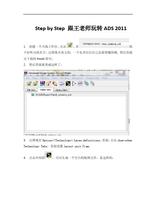
Step by Step 跟王老师玩转ADS 20111.创建一个天线工作区,点击,在取个好听点的名字,记得要全英文的,一个礼拜以后自己还看得懂的哦,然后直接点下面的Finish即可;2.然后界面就变成这样了:3.记得现在Option-》Technology->Layer definitions,里面,点击show other Technology Tabs,里面设置layout unit为mm。
4.点击中间的,可以生成一个空白的版图文件,是这样的:;5.点击上面的Opinions->Preferences,选择最后面对Units/Scale,里面设置各种量纲单位,把长度单位设置为mm;6.把贴片天线画上去,点击右上方的,在版图上随便画出一个矩形,然后双击这个矩形,可以修改其坐标和长宽,改成:这样就创建了一个宽30mm,高25mm的矩形天线雏形;你可以尝试修改这些坐标和尺寸看看有什么变化。
7.我们还需要告诉ADS软件,我们是在怎么样的介质基板上做天线的,在【Options】> 【Technology】>【Material definitions】从数据库选择FR_4,并做修改8.天线的材料可以用Cu,是在上面【Material definitions】的Conductors 里面添加的9.打开[EM]->【Simulation Setup】,Substrate 和 Ports 选项后各有一个黄色的警示图标里面可以看到哪些部分还没做设置,上面我们只设置了基板的材料,但是基板几何结构参数还没设置,比如基板厚度,层数等。
10.选择默认的基板名称Substrate1,这时打开设计窗口。
11.这是一个默认图层的3D基板View,这个基板有一个导电层,一个介质层,还有默认的边界条件。
新建基板都是从这一步开始的。
查看右侧的信息栏,它告诉你怎样进行选择、添加、删除项目。
12.接下来将引导你设置叠层,映射导电层及过孔,使用元件库工艺材料:a. 点击设置窗口中的带状线图形,带状线轮廓被选中,相应的右侧显示带状线的属性。
ADS教程
Hello World!入门范例下面以一个通过44B0的UART0输出字符串“Hello World!”的小程序为例简单讲解一下ADS的初步使用。
本范例的阅读对象是初学者,并假设初学者已经安装ADS1.2(ARM Developer Suite)软件。
首先通过“开始”->“程序”->“ARM Developer Suite V1.2”->“Codewarrior for ARM Developer Suite”打开Codewarrior,Codewarrior是Metrowerks公司为ARM公司所开发的IDE。
图1,新建工程ADS为用户提供了7个模板,分别是:ARM Executable Image:用于由ARM指令的代码生成一个ELF格式的可执行映象文件;ARM Object Library:用于由ARM指令的代码生成一个armar格式的目标文件库;Empty Projec t:用于创建一个不包含任何库或者源文件的工程;Makefile Importer Wizard:用于将VC的nmake或者GNU make文件转入到Code Warrior IDE工程文件;Thumb ARM Executable Imag e:用于由ARM指令和Thumb指令的混合代码生成一个可执行的ELF格式的映象文件;Thumb Executable image:用于由Thumb指令创建一个可执行的ELF格式的映象文件;Thumb Object Library:用于由Thumb指令的代码生成一个armar格式的目标文件库。
一般情况下均选择“ARM Executabel Image”,然后在“Project name:”栏输入工程名称,在“Location:”栏指定路径,本例子的工程名称为“Hello”,点击确定后“Hello”工程建立。
图2,设置工程路径和工程名工程建立以后将生成一个空的工程管理窗口,如下图所示:图3,工程管理窗口接下来就是向工程内添加和建立目标文件了,由于44B0学习评估板具有较多的资源,故其启动文件也较为复杂,所以一般都是直接打包使用,因此在添加启动文件之前请先将“44B0EVB”文件夹复制到“Hello”工程目录下,然后通过工程管理窗口进行启动文件的添加,如下图所示:图4,建立Group先通过点击右键选择“Create Group”,建立一个“44B0X”文件夹,然后再右键选择“Add Files…”来添加启动文件,如下图所示:图5,添加启动文件图6,添加文件到Target在添加文件的过程中你可能已经发现了CodeWarrior IDE为用户建立了三个Target,分别是“DebugRel”、“Realse”、“Debug”,这三个Target分别表示三种调试方式。
ADS2011教程

ADS 2011 实验练习本实验是针对已经熟悉ADS2009 及早先版本的用户所设计,主要目的是帮助客户熟悉ADS2011的新版本。
Copyright 2011 Agilent Technologies实验一: ADS 2011基础重要提示: 这个实验的实验环境是ADS2011,面向对ADS2009或者以前版本有一定经验的用户。
1. 工程文件从project 文件转换为Workspace 文件a. 启动ADS2011:可以通过桌面快捷方式或者开始菜单中的命令启动软件,关闭弹出的“开始使用”对话框。
(可以在以后的时间里学习里面内容)b. 在ADS 主窗口,单击菜单栏下:【File 】—>【Convert Project to Workspace 】c. 弹出提示框:选择需要转换文件的路径:/examples /Training /Conversion_Sample (软件安装目录下),选择待转换的工程文件WORKSHOP_prj 。
这个文件是ADS 自带的一个工程文件,它是用来演示怎么把Project 文件转换为Workspace 文件的。
d. 选中WORKSHOP_prj 后,出现转换向导界面,查看转换向导信息,然后点击下一步。
e. 为Workspace 文件取名,如:lab_1_wrk 。
不要使用已经存在的文件名,否则会提醒你重新给Workspace 文件命名。
定义Workspace 文件所在的路径。
注意:不要在examples 路径下建立_wrk文件,可以选在users/default 或者其他路径。
点击下一步……Lab : ADS 2011 WorkshopCopyright 2011 Agilent Technologiesf.Libraries (元件库): 去除DSP 元件库前的复选框,这里不需要其他的元件库。
当然,可以加入一些其他的元件库到这个Workspace 中。
在 “.prj”文件转换为 “.wrk ”过程中,会产生一个服务于 “.wrk ”的元件库。
ADS中文教程
目录:1、电路模拟基础2、系统模拟基础3、DC模拟和电路模型4、AC模拟和调整5、S参数模拟和优化6、滤波器:瞬态,设计指导,momentum(无源电路的2.5D模拟工具),DAC7、谐波平衡模拟8、电路包络模拟9、最终电路/系统模拟本教程是设计一个用于1900MHz GSM的RF接收系统,包含的部件主要有:1、 200MHz由集总参数元件构成的低通滤波器2、 1900MHz由微带线构成的带通滤波器3、 1900MHz的功放4、把1900MHz变到200MHz的混频器5、其他小部件在完成这个系统的过程中,就可以掌握目录所示的内容。
Xplay2003年9月第一章电路模拟基础 (3)概要 (3)目标 (3)目录 (3)开始 (3)『1』运行ADS (3)『2』建立新项目 (4)『3』检查你的新项目内的文件 (5)『4』建立一个低通滤波器设计 (5)『5』设置S参数模拟 (6)『6』开始模拟并显示数据 (7)『7』储存数据窗口 (9)『8』调整滤波器电路 (10)第二章系统模拟基础 (12)概要 (12)目标 (12)目录 (12)开始 (13)『1』建立一个新的系统项目和原理图 (13)『2』建立一个由行为模型构成的RF接收系统 (13)『3』设置一个带频率转换的S参数模拟 (14)『4』画出S21数据 (16)『5』提高增益,再模拟,绘制出另一条曲线 (16)『6』设置一个RF源和一个带相位噪声的本振LO (17)『7』设置一个谐波噪声控制器 (18)『8』设置谐波模拟 (20)『9』模拟并画出响应:pnmx和V out (21)第一章电路模拟基础概要这一章包括基础界面、ADS文件、原理图、模拟、和数据显示等内容。
另外还有一个简单的例子。
目标建立一个新的项目和原理图设计设置并执行S参数模拟显示模拟数据和储存在模拟过程中调整电路参数使用例子文件和节点名称执行一个谐波平衡模拟在数据显示区写一个等式目录『1』运行ADS『2』建立新项目『3』检查你的新项目内的文件『4』建立一个低通滤波器设计『5』设置S参数模拟『6』开始模拟并显示数据『7』储存数据窗口『8』调整滤波器电路『9』模拟一个RFIC的谐波平衡『10』增加一个线标签(节点名称),模拟,显示数据开始『1』运行ADS很简单,在开始菜单选择图标,运行后界面如下:『2』建立新项目a.在主窗口,点击图标:View Startup Directory。
ARM开发环境

第11章ARM开发环境ADS 1.2
11.1 ADS 1.2简介
ARM ADS全称为ARM Developer Suite,是ARM公司推出的新一代ARM集成开发工具。
现在ADS的最新版本是1.2,它取代了早期的1.1和1.0,除了可以安装在windows NT4、windows 2000、windows 98和windows95操作系统下,还支持windows ME和windows XP 操作系统。
ADS由命令行开发工具、ARM实时库、GUI开发环境(Code Warrior和AXD)、实用程序和支持软件组成。
有了这些部件,用户就可以为ARM系列的RISC处理器编写和调试自己开发的应用程序了。
下面介绍ADS的各个组成部分。
11.1.1 命令行开发工具
这些工具完成将源代码编译、链接成可执行代码的功能。
ADS提供以下命令行开发工具。
1.armcc
armcc是ARM C编译器。
这个编译器通过Plum Hall C V alidation Suite为ARSI C的一致性测试。
armcc用于将用ANSIC编写的程序编译成32位ARM指令代码。
因为armcc是我们最常用的编译器,下面对其进行详细的介绍。
在命令控制台环境下,输入命令:
armcc-help
《ARM嵌入式系统开发典型模块》免费样章。
ADS教程

用ESC结束放置元件和仿真控件命令。并使用图标 调整这些元件的参数如下图所示:
图十三、调整后的电路参数
5
a.双击齿轮状S参数控件标记,打开S参数控件配置窗口,把Step-size改成0.5GHz,选择ok。
图十四、修改仿真控件的步长
b.在上面的窗口点击display标签,会显示所有可以显示在原理图中所有的仿真控件控制量。
6.开始模拟并显示数据………………………………………………………… 7
7.储存数据窗口………………………………………………………………… 9
8.调整滤波器电路………………………………………………………………10
9.模拟一个RFIC的谐波平衡………………………………………………… 12
10.增加一个线标签(节点名称),模拟,显示数据……………………………16
图九、元件库示意图
d.从该选项左边面板中选择电容图标 。然后,在电路图设计窗口放置电容并用 键把电容旋转成竖直状态(见图十)。
e.然后用类似的方法在电路图设计窗口放入电感,利用快捷键 ,把电容器的一端接地。利用快捷键 ,用线把他们连起来。
图十、放置电容图十一、放置电感并把元件连接起来
f.在元件库列表窗口选择Simulation-S_Param项,在该项面板中选择S-parameter模拟控制器(象个齿轮)和端口Term放到图上。
实验一、
概
该实验包括用户基础界面,ADS文件的创建过程包括建立原理图、仿真控件、仿真、和数据显示等部分的内容。该实验还包括调谐与谐波平衡法仿真的一个简单例子。
目
建立一个新的项目和原理图设计
设置并执行S参数模拟
显示模拟数据和储存
在模拟过程中调整电路参数
(完整)ADS使用指南
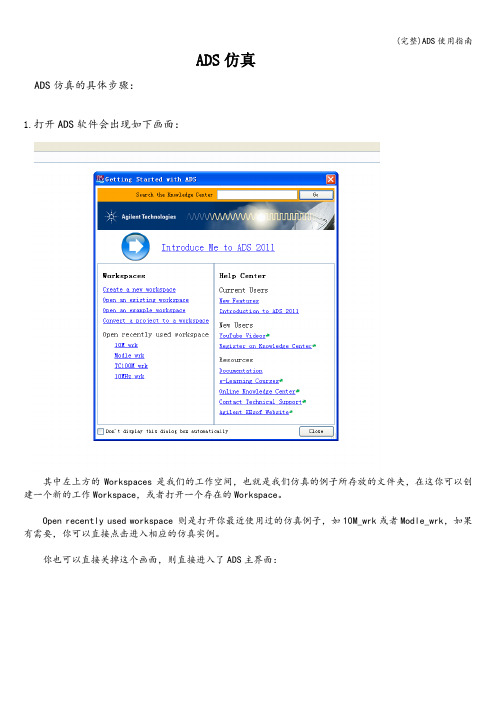
ADS仿真ADS仿真的具体步骤:1.打开ADS软件会出现如下画面:其中左上方的Workspaces是我们的工作空间,也就是我们仿真的例子所存放的文件夹,在这你可以创建一个新的工作Workspace,或者打开一个存在的Workspace。
Open recently used workspace 则是打开你最近使用过的仿真例子,如10M_wrk或者Modle_wrk,如果有需要,你可以直接点击进入相应的仿真实例。
你也可以直接关掉这个画面,则直接进入了ADS主界面:在这你可以通过菜单栏的File-——〉new-——〉workspace 来新建一个仿真实例等效于工具栏中的也可以选择File———〉open---〉workspace 来打开一个存在的仿真实例等效于工具栏中的2.建立一个ADS仿真实例通过File—-->new-—-〉workspace来新建一个仿真实例并命名为Newworkspace_wrk如下图所示:然后完成出现如下界面:这时已经出现了Newworkspace_wrk文件夹.接下来我们就可以在这个文件夹下建立相应的ADS仿真原理图(即Schematic)了。
通过File——>new—-〉Schematic或者直接点击工具栏的则出现如下窗口:其中被选中的cell_1是默认的Schematic名称,我们可以将它更改成10M.这时会产生一个新的窗口:这就是我们建立仿真原理图和执行仿真的窗口。
在此窗口的Lumped-Components目录下我们可以选取原理图所需要的电阻,电容以及电感.在Sources-Freq Domain目录下则可以选中我们需要的直流电压源V_DC.在Passive-RF Circuit目录下选择晶振XTAL2。
在元器件放置到原理图中通常位置都不是我们想要的,因此要对其做相应的调整,选中一个元器件并单击工具栏中的Rotate By Increment 按钮将它顺时针选中90°,也可以使用快捷方式Ctrl+R。
《ADS教程》PPT课件

连线时点右键放 置电源“Power”
更改网络标号
精选课件ppt
37
地的网络标号连接
连线时点右键放 置地“Ground”
更改网络标号
双击地的符号可
更改其网络标号
精选课件ppt
38
8总线绘制
添加总线快捷按钮
方法:点击添加总线 快捷按钮,进入绘制 总线状态,在起始点 点击左键,松开左键 并拖动鼠标,需要拐 弯的地方再点击左键, 在结束点双击左键确 定总线
精选课件ppt
32
PCB的设计内容 后面再进行学习
精选课件ppt
33
7网络标号连接
• 相同网络标号的节点及连线在电气上是连 接的。在PCB当中会要求进行连接。
• 在连线时点击右键,选择右键菜单中的 “Off-page” ,即进入放置“Off-page”状态, 再点击右键,可对“Off-page”进行旋转和 镜像操作,点击左键,即完成放置。
精选课件ppt
15
常用元件—NPN三极管
• 2N3904为TO-92直插式封装, MMBT3904LT1为SOT23贴片式封装。
精选课件ppt
SOT23
TO-9162
常用元件—PNP三极管
• 2N3906为TO-92直插式封装, MMBT3906LT1为SOT23贴片式封装。
精选课件ppt
SOT23
• 放置后出来网络标号设置对话框,在其中 设置网络标号名
精选课件ppt
34
放置“Off-page”
连线时点右键放 置“Off-page”
放置“Off-page” 时点右键作旋转
输入网络标号
精选课件ppt
35
完成效果
网络标号相同,
(完整)ADS2011教程

ADS 2011 Workshop Labs – version 1ADS 2011 实验练习本实验是针对已经熟悉ADS2009 及早先版本的用户所设计,主要目的是帮助客户熟悉ADS2011的新版本。
实验一: ADS 2011基础重要提示:这个实验的实验环境是ADS2011,面向对ADS2009或者以前版本有一定经验的用户。
1. 工程文件从project文件转换为Workspace文件a. 启动ADS2011:可以通过桌面快捷方式或者开始菜单中的命令启动软件,关闭弹出的“开始使用”对话框。
(可以在以后的时间里学习里面内容)b. 在ADS主窗口,单击菜单栏下:【File】—>【Convert Project to Workspace】c. 弹出提示框:选择需要转换文件的路径:/examples /Training /Conversion_Sample(软件安装目录下),选择待转换的工程文件WORKSHOP_prj。
这个文件是ADS自带的一个工程文件,它是用来演示怎么把Project文件转换为Workspace文件的。
d. 选中WORKSHOP_prj后,出现转换向导界面,查看转换向导信息,然后点击下一步。
e. 为Workspace文件取名,如:lab_1_wrk。
不要使用已经存在的文件名,否则会提醒你重新给Workspace文件命名。
定义Workspace文件所在的路径。
注意:不要在examples路径下建立_wrk文件,可以选在users/default或者其他路径。
点击下一步……Copyright 2011 Agilent TechnologiesLab: ADS 2011 Workshopf. Libraries(元件库):去除DSP元件库前的复选框,这里不需要其他的元件库。
当然,可以加入一些其他的元件库到这个Workspace中。
在“.prj”文件转换为“.wrk”过程中,会产生一个服务于“.wrk”的元件库。
ADS使用详解

因为I/O 模式控制寄存器和I/O 数据控制寄存器都是32位的 控制寄存器,所以从0x3ff5000 开始的连续四个地址空间存放的 是I/O 模式控制寄存器的值,I/O 数据控制寄存器的内容是从地 址0x3FF5008 开始的连续四个地址空间存放的内容。IODATA 中 的初始值为0x E7FF0010,因为用的是小端模式,所以读数据的 时候注意高地址中存放的是高字节,低地址存放的是低字节。
传感器
SD卡 放音 录音 电位器 扬声器 网口 网口 USB Device
键 盘
SST39V F800
多功能扩展 口
DA输出
中断 USB Host
扬声器
PS2
由ARM指令的代码 生成一个ELF 格式 的可执行映象文件 创建一个不包含 任何库或者源文 件的工程 将VC的nmake或G NUmake文件转入 到Code Warrior IDE 工程文件 由ARM和Thumb的 指令混合代码生 成一可执行的ELF 格式的映象文件
ARM from ELF设置
Output file name
参照上图进行输出文件名称和路径的设置,须带 上扩展名.bin 或者.hex。当工程文件是从别处copy 过来的时候请记得对该路径进行重新设置,不然将出现 警告提示。 到此为止已经完成基本设置,接下来可以进行编译 和链接。
Remove Object Code操作
Байду номын сангаас
选择调试目标
进入AXD 后通过Option->Configure Target…选 择调试目标。由于当前采用“ARMulator”进行软件仿 真,故选择ARMUL,如下图所示:
查看存储器内容
在程序运行前,可以先查看两个宏变量IOPMOD 和 IOPDATA 的当前值。方法是:从Processor Views 菜 单中选择“Memory”选项。
ADS 入门教程 教程Basics of using ADS

1This chapter covers the user interface basics for file handling, schematic capture, simulation, and data display. In addition, tuning and the use of ADS example files is also covered.Lab 1: Basics of using ADSLab 1: Basics of using ADS1-2OBJECTIVES• Examine the Main window commands and icons • Create a new project and schematic design • Setup and perform an S-parameter simulation • Display the simulation data on a plot and save files • Tune the circuit to refine the response• Look through the Examples and do a Harmonic Balance simulationPROCEDURE1. Start the system (instructor will give you instructions)a. Typically, on a PC, you will use standard method for starting a program or on UNIX, you would type: hpads.Main window (PC version)Lab 1: Basics of using ADS1-3NOTE on Interface Differences between UNIX and PC:: The user interface for the PC and UNIX are the same. The only difference is the appearance and some minor features: For example, UNIX has tear-off menus; the PC version has a Toolbar that can be detached from the window. Otherwise, all the functions and commands are the same for both platforms.2. Examine the Main Window a. Click the File command.These commands are for controlling and handling projects (directories)and designs (files) which are schematics and layouts.Click on any command with ellipses (…) and examine the dialog. Then click the Cancel button as necessary to return.This step is only to show you the menus. Later on, you will be using these commands which are superior to using UNIX commands or PC file managers for ADS.b. Click the View command.These commands are specifically used forchanging and viewing directories. Click on any of the commands to see how they work.c. Click the Options command.These are used to setup global elements for the user interface and for macro recordings.For now, click Preferences… and a dialogbox will appear (shown here).Lab 1: Basics of using ADS1-4d. In the Preference dialog, be sure the Add ProjectExtension box is checked. This means that all projects(directories) you create in ADS will automatically be appended with the extension _prj so that you will recognize them.For this lab, no other preferences should be set.Click OK when finished.e. Click Options > Advanced Design System Setup…When you first install ADS or when your ADS system is updated, you will also see this dialog box. It is used to define which type ofschematic elements and library elements are the default, depending upon the licenses you have. For this lab, be sure the settings look like the picture here – if they do, select Cancel . If not, check with the instructor.f. In the Main window, click the Window command.At this time, most of these commands will not beavailable (inactive) because you have not yet created a project and no other windows are opened. After you create a project, these commands will be available.g. The final Main window command is the Helpcommand. Click Help > Topics and Index and a new window will open. ADS has Help topics and on-line manuals. Spend a few moments looking through the topics and then click Close All.Lab 1: Basics of using ADS1-53. Create a new ProjectFor this step you will use the icons on the Main window. Typically, clicking the correct icon means you have one less mouse click to execute than using the menu commands.In addition, you can identify what an icon does by placing the cursor on the icon. This is called balloon help and is one of the preferences you can turn off or on.a. Try moving the mouse cursor slowly into the bottom of each icon on the Main window. You will see the balloon help and learn the icon names.b. In the Main window, click the icon: View Startup Directory. This will put you in the starting directory for ADS.c. Click: File > New Project .d. When the dialog box appears, give the project a name by typing: lab1.Notice that the length unit is a setting for items such as microstrip lines and also used for layout. For this lab use the default value (mil). Notice that the Browse button allows you to create project directories anywhere you like. Click OKto continue.Create a New ProjectView Startup DirectoryLab 1: Basics of using ADS1-64. Examine the project File Browser and Project HierarchyThe Main window File Browser area should now show that you are in the lab1 project directory. Notice that the sub-directories (data, networks, etc.) were created automatically. Also, the schematic icon is now activated (no longer gray).a. In the main window, double click on the networks directory. The file browser now shows you are in that directory which is empty (no schematics exist).b. To return, double click on the two dots (..) next to the arrow and you will go up one directory.5. Create a Schematic low-pass filter designa. In the Main window, click the New SchematicWindow icon . This is the same as selecting the menucommand : Window > New Schematic Window . Immediately, the Schematic window will appear. If your preferences are set to create an initial schematic, you will have two schematics now opened – close oneof them.Component Palette and scroll barMessages, X-Y location or cursor,and other information.Lab 1: Basics of using ADS1-7b. Save the schematic design: notice the top line (window border)shows the project name (lab1_prj) and the name of the schematic (untitled) with an incremental number (1, 2, 3, …) of the schematic window you have open. To name the schematic, click File > Save As and type in a name such as lpf or low_pass and click Save. This will save it in the networks directory of the lab1 project.c. Examine the commands and icons. Click on the small arrow on theComponent Palette list to see the palette choices. Also, move the Scroll Bar down and up to see how it works.d. In the Lumped Components palette, click on the capacitor “C ” and click the rotate icon as needed to get the correct orientation. Then click to insert the capacitor as shown on the schematic. Next, insert another capacitor.Lab 1: Basics of using ADS1-8e.Continue creating the low-pass filter as shown by inserting theinductor. Then insert grounds and wire the componentstogether. This will give you practice with schematic capture. Youcan try using the copy, move and other icons or commands.f.After the circuit is built, edit the value of C2 = 3 pico-farads. Todo this, click on the component and then click the icon: EditComponent Parameters (same as double clicking the capacitorsymbol). When the dialog box appears – change the value to 3.0, click Apply and OK.g.Next, select the Simulation- S_Param paletteto insert the S-parameter simulation controler(gear icon) and the terminations (Term).ing Component History: After the circuit is built, try deleting acapacitor and then reinserting it by typing in the capital letter C in the Component History window and press Enter. Next, edit the valuedirectly on the schematic by highlighting the value and typing over with the new value (3.0). Verify that it has changed by looking at the value inthe edit dialog box.Simulation ControllerLab 1: Basics of using ADS1-96. Setup and Run the Simulationa. To setup the simulation, double click on the S-parameter simulation controller on the schematic. When the dialog box appears, change the step size to 0.5 GHz and click Apply . Notice how it updates the value on the screen as it reads the entries. The OK button does the same thing and also dismisses the dialog box.b. Click the Display tab and you will see that the Start, Stop and Step values have been checked to be displayed on the simulationcontroller. You will use the display tab for setting other controllers to display the desired settings during this class.c. Click the OK button to dismiss the dialog box.d. Setup the Simulation dataset. The default dataset name is the same as the schematic (lpf ). But you can give the dataset (a file) a name. To do this, click Simulate >Simulation Setup . When the dialog box appears, type in the name like s_data . Then click Apply . In general, the default dataset name is the same name as the schematic design but you can control it using this method.DEFINITION of a DATASET: A dataset is a file that may contain matrices, results calculated fromequations, node voltages, etc. It has the extension .ds which means dataset (results of a simulation). It is important to remember that all datasets are onlly written into the project data directory but the data display windows (.dds files - which means datadisplay server) are not in the data directory, they areunder the project directory.Lab 1: Basics of using ADS1-10e. Click the Simulate icon (gear) to start the simulationprocess. This is the same as clicking Simulate in the setup dialog. When you simulate, the resulting data is always written into the current dataset you have setup.i. Next, look for the Status window to appear and you should see amessage similar to the one here, describing the results of the simulation.SP1 refers to the s-parameter simulation controller and its settings. If no errors occurred, the message tells you the simulation is finished and that the dataset has been written into the data directory in the project you are in (here it is lab1_prj).j. Close the Status window after you see the message. You can always get the status window back using the command: Window > Restore Status . The simulation status information can be restored using the Window command in the status window and then selecting thesimulation from the list.1-117. Display the simulation results (Data Display window)a. Open a data display window from either the Main window or the schematic window by clicking the Data Display icon.b. When the Data Display window opens, the name of the dataset will appear in the list.c. To create the plot, click on the Rectangular Plot icon and move the cursor (with ghost plot) into the window and click. When the next dialog box appears, select the S21 data and click the Add button.d. The next dialog will prompt you to specify the type of data to display. Select dB and click OK . The plot should show a reasonable low pass filter response.e. Put a marker on the trace:Click the menu command:Data Display WindowDataset NamePlots, lists, equations, etc.1-12Marker > New . Select the trace and click to insert the marker. Move the marker using the cursor or the keyboard arrow keys. Also, move the marker text by selecting it and positioning it as desired. Try deleting the marker or putting another marker on the trace.8. Save the Data Display and Schematica. In the Data Display window, notice that it is labeled Untitled . To save this data display window with a name, click File > Save As and type in the name: lab1 and click Save . This means that it will saved as a .dds (data display server) file in the lab1 project directory and it will have access to all data (.ds files or datasets) in the data directory.b. Close the data display and reopen it: After saving lab1.dds, close it by clicking the X in the window corner. Then reopen it as follows: click the data display icon to open the window. Click the File > Open icon and select lab1.dds in the dialog and click Open and it will reappear with your S21 plot. Also, noitce that the default dataset is s_data from yourprevious simulation.NOTE: Use these icons toview the plot as desired.9. Tune the filter circuitThis step introduces the ADS tuning feature that allows you to alter the parameter value(s) of components and see the simulation results. In this step, you first select the components and then select the tuning feature. If you select the tuning feature first,you must select the component parameters and not the components.a. First, in the filter schematic, select (click) the capacitor and inductor to be tuned as shown. Hold down the SHIFT or Ctrl key to select multiple components: C1 and L1.b. Position the data display and the schematic so that you can see them both on the screen. If necessary, size the windows and use the View All command or icon.c. Click the command Simulate > Tuning Immediately, the status (simulation) window will appear along with the tune control dialog box (shown here). Go ahead using the default settings and tune the filter as you watch the data traces appear.View All1-14d. Change the tuning range: In the Tune Control dialog, click the Details button and watch the dialog change from brief to the deatiled. Type in a larger range such as 6 and then tune the filter again. You should be able to see a greater response.e. Continue tuning and when you are satisfied with the results , click the Update button to have the C and L values updated on the schematic. If you click the Component button you will notice that it allows you to add other parameters to the tuning. The Brief button returns to the smaller (brief) Tune Control dialog. When you are satisified with the tuned response, simply click the Cancel button and the plot will contain the final tuned trace such as the one here.f.Save the data display and the schematic.Change theranges here.Change simulation1-1510. Using TemplatesTemplates make it easy to include the required simulation controllers, ports,and other items used in the simulation. In addition, you can create your own templates or customize the existing ones.a. From the Main window, click the Schematic icon and another schematic window will open.b. In the new schematic, click: File >Insert Template and insert the S_Params template.c. Modify the template in some way -for example, change the simulation controller values and then click:File > Save As Template . When the next dialog appears, type in a name for the template:my_template .d. Open a new schematic window (from the Main window) and insert your template in the same way (File > Insert Template). Now you know how to create your own template.e. Click: File > Close Design (do not save the schematic) and close the window.At this point you have stepped though the basics of using Advanced Design System.The following steps will show you the basics of using the Examples directory.1-16About the Examples DirectoryAll of the examples can be examined, including the results of the simulations.However, because the example files should remain unchanged, copy them into your own directory to simulate or modify them.11. Open the Example Directory: RFIC, amplifier_prj, HBtest.dsn a. In the Main window, click on the View Examples Directory icon. You will be prompted to confirm you are changing directories. Afterward,select the RFIC directory and open the amplifier_prj directory.b. Immediately, two schematics windows will open: Readme and aschematic design (ACPRtest). This is how all example files open with some documentation and a particular example.c. In the schematic, click the File > Open icon and you will see other RFIC amplifier designs. Now, open the HBtest.dsn.1-17d. This is the top-level hierarchy of the HBtest.dsn. This is where the simulation is setup and controlled. To see the amplifier the sub-circuit click on the symbol (shown here) and then click the icon: Push into Hierarchy .e.You can go back to the upper level by clicking the reverse arroLower level schematic shows transistor level circuit with model assignments and port connectors.Click here to return to upper level design.1-18f. After you return to the upper level, examine theHarmonic Balance controller by double clicking on it or by selecting it and clicking the edit icon.As you can see, the Harmonic Balance controller has many tabs for setting up the type of simulation that you want.The purpose of this step is only to get you acquainted with the simulation controller. Look through the tabs and Cancel when you are done.g. To see the data from this simulation, click on the icon: New DataDisplay . When the window opens, click on File > Open . Then select the HBtest data display and click Open . This is how you can open yourown saved data display files and access the data in the datasets.1-19The data display window will appear. Examine the data and notice that “Vout” in the equation is a named node point on the schematic. When finished, close the display and schematic window. Later on, you will be setting up these same simulations.12. Delete the lab1 project directoryBecause you are in another directory (Examples directory), you can use the Main window command File > Delete Project to delete the lab1 project.You must be in a different project to delete another project.This lab exercise ends here.EXTRA EXERCISE : If you finish the lab early, spend more time examining the Examples directory designs or try using the Layout window. Or, go back and trybuilding a better low pass filter.。
ADS教程第11章
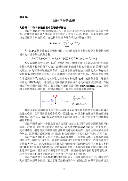
附录B :谐波平衡仿真器大信号AC 和S-参数仿真中的谐波平衡法谐波平衡法是一种频域分析方法,用在对非线性电路和系统的失真进行仿真。
这种方法假设输入激励由相关的稳态正弦信号组成。
因此,结果能被表达成稳态正弦信号和的形式,它包括除谐波和混合项之外的输入频率。
0()()k Njw t k k v t real v e ==∑k v 是k*ω频率处的复振幅和相位。
电路仿真器把非线性微分方程变换为频域中的一组非线性代数方程。
*((()))((()))*()()k k k k k m k j F q v t F f v t V H j I ωωω++=()k F 表示傅立叶变换中的th k 项频谱分量。
谐波平衡仿真器必须同时求解出非线性代数方程中的所有k v 值。
必须求解的非线性方程的个数按N 的因子的形式增加,N 与标准时域模拟器有关。
这意味着谐波平衡法中矩阵的大小和存储容量随着N 的变大增加很快。
为了在时域中对非线性器件求值,仍然需要采用傅立叶逆变换将k v 变换为()v t ,在这之前应先对非线性 q()和f()函数求值。
这表示标准的SPICE-类型、非线性电流和载荷波形在每个迭代点被变换到频域,在频域方程中用到它们的谱值。
很多谐波平衡仿真器用到New-Raphson 方法,派生物(非线性电阻和电容)必须在时域中计算并且需要被变换到频域。
时域求解中应用谐波平衡法的主要优点是对线性器件的任意频响比较容易迅速地模拟。
它不再需要集总参数元件的近似值。
时域卷积被比较容易的频域相乘代替,这对RF 、微波和毫米波频率来说特别重要,它们经常需要用频域数据描述其特性。
谐波平衡法的另一个优点是能直接提供稳态结果,而不必要等到瞬态信号的结束。
对高Q 值电路这是费时的等待。
输入激励的频率ω可以被任意扩展并且是不对称的,但是谐波平衡法仍然能比较快速的得到结果。
复杂性和求解成本不会增加,这是因为低频调谐(长时期)和高频调谐(非常小的时间步)共同存在。
ADS中文教程

目录:1、电路模拟基础2、系统模拟基础3、DC模拟和电路模型4、AC模拟和调整5、S参数模拟和优化6、滤波器:瞬态,设计指导,momentum(无源电路的2.5D模拟工具),DAC7、谐波平衡模拟8、电路包络模拟9、最终电路/系统模拟本教程是设计一个用于1900MHz GSM的RF接收系统,包含的部件主要有:1、 200MHz由集总参数元件构成的低通滤波器2、 1900MHz由微带线构成的带通滤波器3、 1900MHz的功放4、把1900MHz变到200MHz的混频器5、其他小部件在完成这个系统的过程中,就可以掌握目录所示的内容。
Xplay2003年9月第一章电路模拟基础 (3)概要 (3)目标 (3)目录 (3)开始 (3)『1』运行ADS (3)『2』建立新项目 (4)『3』检查你的新项目内的文件 (5)『4』建立一个低通滤波器设计 (5)『5』设置S参数模拟 (6)『6』开始模拟并显示数据 (7)『7』储存数据窗口 (9)『8』调整滤波器电路 (10)第二章系统模拟基础 (12)概要 (12)目标 (12)目录 (12)开始 (13)『1』建立一个新的系统项目和原理图 (13)『2』建立一个由行为模型构成的RF接收系统 (13)『3』设置一个带频率转换的S参数模拟 (14)『4』画出S21数据 (16)『5』提高增益,再模拟,绘制出另一条曲线 (16)『6』设置一个RF源和一个带相位噪声的本振LO (17)『7』设置一个谐波噪声控制器 (18)『8』设置谐波模拟 (20)『9』模拟并画出响应:pnmx和V out (21)第一章电路模拟基础概要这一章包括基础界面、ADS文件、原理图、模拟、和数据显示等内容。
另外还有一个简单的例子。
目标建立一个新的项目和原理图设计设置并执行S参数模拟显示模拟数据和储存在模拟过程中调整电路参数使用例子文件和节点名称执行一个谐波平衡模拟在数据显示区写一个等式目录『1』运行ADS『2』建立新项目『3』检查你的新项目内的文件『4』建立一个低通滤波器设计『5』设置S参数模拟『6』开始模拟并显示数据『7』储存数据窗口『8』调整滤波器电路『9』模拟一个RFIC的谐波平衡『10』增加一个线标签(节点名称),模拟,显示数据开始『1』运行ADS很简单,在开始菜单选择图标,运行后界面如下:『2』建立新项目a.在主窗口,点击图标:View Startup Directory。
ADS软件学习 基础教程

ADS软件学习目录一、ADS软件简介 (3)1.1 为谁服务 (3)1.2 提出问题 (3)二、ADS软件主要模块及功能 (4)2.1主要模块 .................................................................................... 错误!未定义书签。
三、输入输出文件特性(不全) (6)四、ADS中如何启动新项目并系统建模 (7)4.1 启动ADS软件 (7)4.2 创建新项目 (7)4.3 系统建模 (9)4.3.1 打开原理图窗口(Schematic window) (9)4.3.2 查找元器件 (10)4.3.3 绘制原理图 (12)4.3.4 仿真模拟 (13)基于Advaced Design System(简称ADS)软件资料的学习进行如下总结:对ADS 软件用途、模块简介、各模块的功能进行描述,本文主要针对在原理图模块中进行电子电路的仿真过程的描述。
一、ADS软件简介1.1 为谁服务先进设计系统(Advanced Design System),简称ADS,是安捷伦科技有限公司(Agilent)为适应竞争形势,为了高效的进行产品研发生产,而设计开发的一款EDA软件。
软件迅速成为工业设计领域EDA软件的佼佼者,因其强大的功能、丰富的模板支持和高效准确的仿真能力(尤其在射频微波领域),而得到了广大IC设计工作者的支持。
ADS是高频设计的工业领袖。
它支持系统和射频设计师开发所有类型的射频设计,从简单到最复杂,从射频∕微波模块到用于通信和航空航天∕国防的MMIC。
1.2 提出问题通过从频域和时域电路仿真到电磁场仿真的全套仿真技术,ADS让设计师全面表征和优化设计。
单一的集成设计环境提供系统和电路仿真器,以及电路图捕获、布局和验证能力——因此不需要在设计中停下来更换设计工具。
ADS是强大的电子设计自动化软件系统。
它为蜂窝和便携电话、寻呼机、无线网络,以及雷达和卫星通信系统这类产品的设计师提供完全的设计集成。
ADS2017快速入门中文教程.pdf

使用函数
你可以利用等式对仿真中产生的数据的进行操作。这些等式使用基于 AEL, Application Extension 语言的函数很有创造性。
选择File>Archive Project,然后利用对话框定位并存档项目。
第二章: 使用 ADS 的设计
ADS 使用设计来存储你达到你设计目标而生成的原理图和布局图信息。 一个设计可以由单个的原理图或布局图组成,或者它可以由许多作为单个设计包含的 内部子网络的原理图和布局图组成。项目中的所有设计都可以直接从主窗口或从一个设计 窗口内显示和打开。在一个设计窗口中你可以:
被提示去保存你对它所做的任何修改。 使用下面的方法可以打开一个项目: 1. 选择File>Open Project,然后使用对话框定位并打开项目。 2. 使用主窗口上的File Browser栏定位项目并双击来打开它。
共享项目 使用主窗口可以重新使用和共享项目而不需要手动包括所有组成项目的个体部分。 1. 添加链接来创建一个分级项目 选择File>Include/Remove Projects,然后使用对话框定位并链接到这个项目。 2. 创建拷贝来复制一个项目 选择File>Copy Project,然后使用对话框定位并拷贝这个项目。 3. 存档/不存档来转移一个简洁的项目存档文件
制 RF 信号的快速、完整的分析。
LSSP 仿真控制器 执行大信号 S 参数分析来描述非线性行为。附随的 P2D 仿
真器可以加快随后的分析。 XDB 仿真控制器
寻找一个用户定义的增益压缩点,在那一点上实际功率曲 线偏离理想线性功率曲线。 瞬态仿真控制器
完全在时域中利用一个简化的模型解决非线性电路来说明 分布式元件的频率响应。
- 1、下载文档前请自行甄别文档内容的完整性,平台不提供额外的编辑、内容补充、找答案等附加服务。
- 2、"仅部分预览"的文档,不可在线预览部分如存在完整性等问题,可反馈申请退款(可完整预览的文档不适用该条件!)。
- 3、如文档侵犯您的权益,请联系客服反馈,我们会尽快为您处理(人工客服工作时间:9:00-18:30)。
附录B :谐波平衡仿真器大信号AC 和S-参数仿真中的谐波平衡法谐波平衡法是一种频域分析方法,用在对非线性电路和系统的失真进行仿真。
这种方法假设输入激励由相关的稳态正弦信号组成。
因此,结果能被表达成稳态正弦信号和的形式,它包括除谐波和混合项之外的输入频率。
0()()k Njw t k k v t real v e ==∑k v 是k*ω频率处的复振幅和相位。
电路仿真器把非线性微分方程变换为频域中的一组非线性代数方程。
*((()))((()))*()()k k k k k m k j F q v t F f v t V H j I ωωω++=()k F 表示傅立叶变换中的th k 项频谱分量。
谐波平衡仿真器必须同时求解出非线性代数方程中的所有k v 值。
必须求解的非线性方程的个数按N 的因子的形式增加,N 与标准时域模拟器有关。
这意味着谐波平衡法中矩阵的大小和存储容量随着N 的变大增加很快。
为了在时域中对非线性器件求值,仍然需要采用傅立叶逆变换将k v 变换为()v t ,在这之前应先对非线性 q()和f()函数求值。
这表示标准的SPICE-类型、非线性电流和载荷波形在每个迭代点被变换到频域,在频域方程中用到它们的谱值。
很多谐波平衡仿真器用到New-Raphson 方法,派生物(非线性电阻和电容)必须在时域中计算并且需要被变换到频域。
时域求解中应用谐波平衡法的主要优点是对线性器件的任意频响比较容易迅速地模拟。
它不再需要集总参数元件的近似值。
时域卷积被比较容易的频域相乘代替,这对RF 、微波和毫米波频率来说特别重要,它们经常需要用频域数据描述其特性。
谐波平衡法的另一个优点是能直接提供稳态结果,而不必要等到瞬态信号的结束。
对高Q 值电路这是费时的等待。
输入激励的频率ω可以被任意扩展并且是不对称的,但是谐波平衡法仍然能比较快速的得到结果。
复杂性和求解成本不会增加,这是因为低频调谐(长时期)和高频调谐(非常小的时间步)共同存在。
谐波平衡法的限制是信号必须具有准周期性,且能被表示成一系列离散频率和的形式。
随着N 值变大,需要的内部存储空间数量变的很大,内部矩阵的大小随着2N 增加,这意味着在仿真任意的持续时间长的调制信号和具有很多不同的LO 和RF 频率系统的时候,它的效率将变低。
仿真高频电路的瞬态响应实际上是不可能的,因为波形必需是准周期性的。
频谱必需由离散的稳态的谱组成。
对于当今计算机的实际限制是对中等尺寸电路的64位调频。
谐波平衡法对于仿真模拟RF 和微波问题是一种通常的选择方法,因为它们大多需要在频域中处理。
适合于这类分析的器件和电路包括:在具有正弦曲线大信号驱动下的功率放大器、频率乘法器、混频器和调制器。
从高频电路和系统仿真中可以看出,谐波平衡法同时域卷积的瞬态分析法相比还有许多优点:●设计者通常关心的是系统的稳态状况。
很多高频电路含有大的时间常数,为了达到稳态,通常的瞬态方法需要将很多低频正弦曲线在多个周期内合成。
如果采用谐波平衡法,可以直接得到稳态谱响应。
●应用的电压源具有典型的多频声正弦曲线,它有很窄或是很宽的剩余频带。
通常情况下,当前最高频率的响应比最低频率的响应幅度大很多倍。
瞬态分析法需要对最高频率正弦曲线的大量周期进行合成。
在很多实际情况中,是不允许花费这么多时间的。
●在高频下,很多线性模型在频域中能被很好的表示。
在时域中通过卷积法对这类元件的仿真将在精度、因果关系或稳定度上产生问题。
元件面板列表提供了谐波平衡仿真的种类:Simulation-HB——一通用谐波平衡仿真Simulation-LSSP——大信号S—参数仿真Simulation-XDB——用于寻找增益—压缩点在Simulation-HB面板中的Harmonic Balance Simulation 组件,用它能够得到频域中的电压和电流。
用这个组件可以得到以下结果:●测定电路中电压或电流的谱成分,通过扩展,可以计算三阶截距(TOI或IP3 ),总谐波失真(THD),互调失真成份(在多频响激励中)。
●功率放大器满载轮廓分析。
●非线性噪声分析。
在Simulation-LSSB面板中,非线性LSSP Simulation 组件使计算非线性电路的大信号S—参数变得容易,例如在使用功率放大器和混频器的场合中。
在后面的情况中,大信号S—参数通过“across frequency”进行计算,即由RF输入得到IF输出。
为了写出仿真结果,需要用到基于文件的放大器(例如放大器P2D组件,在System&Mixers面板中),在Simulation-LSSP面板中用P2D来进行分析。
用这个文件能提高随后的仿真速度。
在Simulation-XDB面板中,XDB Simulation组件可以自动确定放大器或混频器的X dB增益压缩点。
模拟器从一个小的输入值向上扫描,在得到满足要求的增益压缩点时停止。
以上提到的组件都有可选择的种类●Small—signal mode(在LSSP simulator 中不可用)小信号/大信号分析法,当RF输入可被作为小信号扰动,同时大信号LO组件可用完全谐波平衡分析方式计算时,能提高混频器的仿真速度。
小信号/大信号分析法能用在许多涉及大信号和小信号调谐的特定场合中。
●Nonlinear Noise 用来进行非线性点噪声或扫描噪声仿真,并且可以计算带噪声的两端口参数。
●Oscillator—Analysis 用来分析振荡器,包括相位噪声。
谐波平衡仿真操作谐波平衡仿真使的电路的多频声仿真成为可能,它列出了互调频率变化。
这包括谐波间的频率变化。
不但电路自身产生谐波,每个信号源(激励)也产生谐波或小信号边带。
激励由与源有关的直到12次非谐波组成。
考虑到实际情况,系统中总的频率个数由于考虑到实际存储容量,交换空间和仿真速度而受到限制。
谐波平衡法是一种迭代方法。
它是基于以下假设,对一个给定的正弦激励,存在一个能用有限的傅立叶级数表示且满足精度要求的稳态解。
因此,电路的节点电压对所有频率成分呈现出一系列的幅度和相位。
从节点流入线性元件包括所有的分布参数元件的电流直接以频域线性分析的方法计算,从节点流入非线性器件的电流在时域中计算。
从节点中流出的所有电流在频域可以表示出来,根据Kirchhoff’s电流定律(KCL),在所有的节点上电流总合为0。
第一次迭代得到这样结果可能性是非常小的。
因此,误差函数用来表示所有节点上的计算电流之和。
误差函数是检测遵守KCL的数量标准,根据这个标准调整电压的幅度和相位。
如果方法收敛(即误差函数能得到一个很小的值),则所求电压的幅度和相位接近稳态值。
Krylov 子空间求解器现代谐波平衡仿真器依靠New —Raphson 方法求解非线性系统的代数方程,它来源于大信号频域电路仿真问题。
每次New —Raphson 迭代都需要将与非线性系统方程联系的Jacobian 矩阵进行反变换,如果矩阵采用直接的方法计算,所需要的空间以2()O H 增加,H 是谐波个数。
因此,Jacobian 的因式分解当H=500时所需要的RAM 空间是H=10时的2500倍。
一种可替代的方法是采用Krylov 子空间迭代法,例如GMRES (generalized minimum residual )。
这种方法不需要对Jacobian 矩阵J 直接存储,仅需要以J*V 的方式运行矩阵—矢量乘积,其中V 是任意矢量。
此时需要的存储空间变为()O H ,而不是上面谐波平衡法中的2()O H 。
对大的谐波平衡问题,Krylov 求解器可节省大量的存储空间。
类似的讨论说明可得到更高的计算速度。
大信号S —参数仿真基础小信号S —参数,它是基于线性电路的小信号仿真,而大信号S —参数是基于非线性电路的谐波平衡仿真。
由于谐波平衡法是大信号仿真方法,因此它的求解包括非线性作用的影响,例如压缩。
这表示大信号S —参数能随着功率电平的改变而改变,由于这个原因,大信号S —参数也被称作依赖于功率的S —参数。
类似小信号S —参数,大信号S —参数的定义也是采用反射波和入射波之比。
i ij jB S A =入射波和反射波定义如下: 2*j oj V Z I A R -= 2*i oi i i oi B R =其中:i V 和j V 是傅立叶系数,表示在端口i 和j 的基频电压;i I 和j I 是傅立叶系数,表示在端口i 和j 的基频电流;0i Z 和0j Z 是端口i 和j 的参考阻抗;oi R 和oj R 是0i Z 和0j Z 的实部。
这个定义是小信号S —参数的一般定义形式,其中V 和I 是傅立叶系数而不是矢量。
对于线性电路,定义简化为对小信号的定义。
为了计算两端口的大信号S—参数,仿真器需要进行以下操作。
1.在端口2连接一个与参考阻抗共轭的阻抗,在端口1用户给定一个功率电平为P1的信号,采用一个阻抗值与端口参考阻抗共轭的源。
用谐波平衡法计算端口1,2 的电流和电压值,由此计算S11和S21。
2.在端口1连接一个与参考阻抗共轭的阻抗,在端口2施加一个功率电平为2211p S P的信号,采用一个阻抗值与端口2的参考阻抗值共轭的源,用谐波平衡法计算端口1,2 的电流和电压值,由此计算S12和S22。
非线性噪声仿真基础谐波平衡仿真的结果是数据集的输出,并用来确定非线性噪声仿真的周期工作点。
周期工作点是电路在基波、谐波和混频情况下的稳态电压和电流。
每个上部和下部的噪声边带被每个大信号频谱分量模拟。
因此,噪声频率被模拟的个数是谐波频率的两倍,需要存储稀疏矩阵的空间变为4倍(除非选中Krylov项)。
所以,非线性噪声仿真所需要的存储空间是正常谐波平衡仿真的4倍。
对Maximum order设定比较低的参数值可以限制所需的计算空间。
在噪声仿真中如果存储空间不够用,在输入中去除大信号调频项,并用一个Term元件代替,也可以在谐波平衡仿真组件中减少调谐个数,噪声数据的仿真结果不会有很大的变化。
如果需要噪声数据,给电路添加端口。
另外,因为用到噪声数据的单边带定义,必须由参数Input frequency指定正确的输入边带频率。
此输入频率可同感兴趣的点噪声频率混频。
如果没有输入指定频率,则它被假设和点噪声频率相同。
这种情况下,输入和输出频率是相同的,放大器就是一个典型的例子。
输入频率是指进入混频器RF端口的频率。
对混频器来说,输入频率由本地振荡器频率和噪声频率组成的方程决定。
这些值之间采用和或差的形式取决于发生的是上变换还是下变换。
如果在上边带或是下边带中没有找到满足指定输入频率的值,将会产生一个警告并且采用最近的边带。
如果需要带噪声的两口参数,例如opt S 、n R 或是min NF ,选择Calculate noisytwo –port parameters 。
