how to use fastener
洁净的Honda CBR1000RR RA S1 S2迅速变速器手把说明书
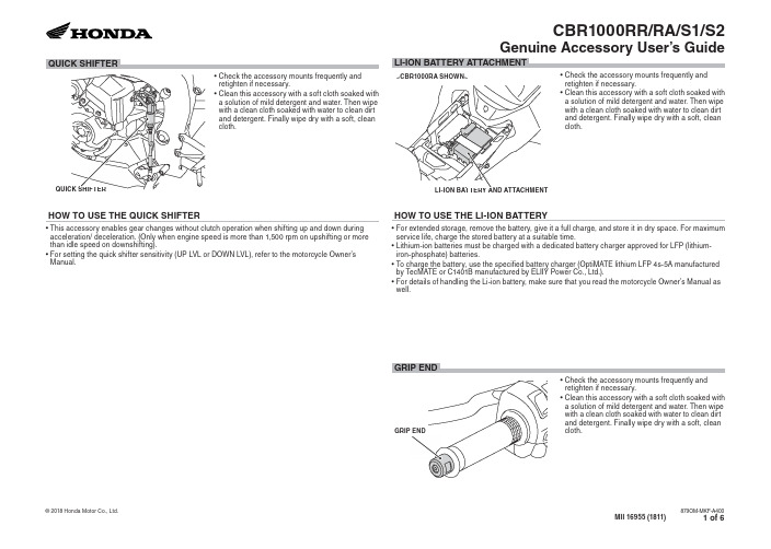
LI-ION BATTERY AND ATTACHMENT
HOW TO USE THE LI-ION BATTERY
• Check the accessory mounts frequently and retighten if necessary.
• Clean this accessory with a soft cloth soaked with a solution of mild detergent and water or a cleaner.
• Clean this accessory with a soft cloth soaked with a solution of mild detergent and water. Then wipe with a clean cloth soaked with water to clean dirt and detergent. Finally wipe dry with a soft, clean cloth.
• Clean this accessory with a soft cloth soaked with a solution of mild detergent and water. Then wipe with a clean cloth soaked with water to clean dirt and detergent. Finally wipe dry with a soft, clean cloth.
Cherry Aerospace G704B 紧固件工具说明书

TM-G704B Rev.: C DCR# 16-0431 DATE: 06/02/16 Federal Identification Code: 11815 © 2016 Cherry Aerospace1224 E. Warner Ave, Santa Ana, Ca 92705 Tel: 1-714-545-5511Original InstructionsG704BCOMPACT CHERRYMAX®POWER TOOLLOCTITE® is a registered trademark of Henkel Corporation DEXRON® is a registered trademark of GM Corporation. PARKER® is a trademark of Parker Hannifin Corporation THE G704B TOOLTABLE OF CONTENTSDescription (3)Technical Specifications (3)Putting the Tool in Service (3)General Operation Safety Warnings (4)Operating Instructions (5)Pulling Head Selection for Blind Fasteners (5)Pulling Head Selection for Cherry Rivetless Nutplate Products (6)Pulling Head Extensions Available (6)Riveter Repair and Maintenance (7)Tools and Service Kits Needed (7)Service Procedure (8)Head Cylinder Subassembly (8)Handle Subassembly (8)Air Valve Subassembly (8)Component List and Other Accessories (9)Cross Section View (10)Top Assembly (G704B) – Exploded View (11)Head Cylinder Subassembly (704B35) - Exploded View (12)Power Handle Subassembly (704-086) - Exploded View (13)Priming the Hydraulic System (14)RecommendedHydraulic Fluids (14)FluidHandling Safety (14)BleedingInstructions (15)Troubleshooting Guide (15)Declaration of Conformity (16)Seller warrants the goods conform to applicable specifications and drawings and will be manufactured and inspected according to generally accepted practices of companies manufacturing industrial or aerospace fasteners. In the event of any breach of the foregoing warranty, Buyer’s sole remedy shall be to return defective goods (after receiving authorization from Seller) for replacement or refund of the purchase price, at the Seller’s option. Seller agrees to any freight costs in connection with the return of any defective goods, but any costs relating to removal of the defective or nonconforming goods or installation of replacement goods shall be Buyer’s responsibility. SELLER’S WARRANTY DOES NOT APPLY WHEN ANY PHYSICAL OR CHEMICAL CHANGE IN THE FORM OF THE PRODUCT IS MADE BY BUYER.THE FOREGOING EXPRESS WARRANTY AND REMEDY ARE EXCLUSIVE AND ARE IN LIEU OF ALL OTHER WARRANTIES AND REMEDIES; ANY IMPLIED WARRANTY AS TO QUALITY, FITNESS FOR PURPOSE, OR MERCHANTABILITY IS HEREBY SPECIFICALLY DISCLAIMED AND EXCLUDED BY SELLER. THIS WARRANTY IS VOID IF SELLER IS NOT NOTIFIED IN WRITING OF ANY REJECTION OF THE GOODS WITHIN ONE (1) YEAR AFTER INITIAL USE BY BUYER OF ANY POWER RIVETER OR NINETY (90) DAYS AFTER INITIAL USE OF ANY OTHER PRODUCT.Seller shall not be liable under any circumstances for incidental, special or consequential damages arising in whole or in part from any breach by Seller, AND SUCH INCIDENTAL, SPECIAL, OR CONSEQUENTIAL DAMAGES ARE HEREBY EXPRESSLY EXCLUDED.For more information please contact our Technical Services Department at Tel. 714-850-6022WARRANTYDESCRIPTIONThe Cherry® G704B riveter is a compact but powerful riveter designed for highproductivity, reliable installation of the most popular sizes of aircraft blind fasteners.TECHNICAL SPECIFICATIONSCherry® Aerospace (CHERRY®) policy is one of continuous development. Specifications shown in this document may be subject to change which may be introduced after publication. For the latest information always consult CHERRY®. AIR PRESSURE 90 to 110 PSI (6.2 to 7.6 bar) STROKE ½ inch (11.1 mm)MIN. PULLING-FORCE: 3,100lbs@90psi(*************)WEIGHT 4.25 lbs. (2.25 kg) CYCLE TIME One Second Approximately NOISE LEVEL 71 dB (A)VIBRATION Less than 2.5 m/s 2AIR CONSUMPTION 3.9 CFM (110.5 liters/M) at 20 Cycles/MinutePUTTING THE TOOL IN SERVICEThe tool must be used with an air pressure regulator. Even if your shop air pressure is below the maximum recommended range, pressure spikes in your air-lines could cause serious damage to the tool or cause safety concerns. Tools equipped with an in-line Air Pressure Regulator (P1505) may be attached to any shopair-line.Tools NOT equipped with an in-line Air Pressure Regulator (P1505) MUST be connected to a dedicated regulated air-line.GENERAL OPERATION and SAFETY WARNINGS∙ Wear proper PPE(Personal Protection equipment)when operating, servicing or repairing thistool∙ Read Manual; operators must be trained in safety and correct tool operation∙ Service and repairs shall be performed only by trained personnel.∙ Do not pull rivet in the air or directed at any person.∙ Do not use the tool with a damaged or missing stem deflector∙ Rotate the Stem Deflector facing away from the operator or critical aircraft structure; use a Stem Catcher if possible.∙ Do not pound on the rear of the tool head to force rivets into holes.∙ Make sure that the air muffler is not obstructed and is directed away from people.∙ Do not exceed the recommended air pressure.To ensure safety, use the pre-set air pressure regulator P/N P1505.∙ Make sure to disconnect from the air supply before service or repair.∙ Wash thoroughly after handling hydraulic fluid.∙ Unauthorized modifications, including using substitute components will void warranty and shall be at the customer's entire responsibility.∙ Do not use any substitutions as they will impact the tool safety and reliability life.OPERATING INSTRUCTIONSBefore using the tool:CAUTION∙ Read the tool manual instructions; before first using the tool.∙ Read and comply to all safety instructions given in this document in addition to the general safety rules applicable ∙ Make sure the tool is connected to an air source operating within the recommended pressure range∙ Before installing the permanent fasteners, make sure that the structure is properly clamped with temporary fasteners∙ Make sure that the correct pulling head is selected for the fastener to be installed and that the tool is in good working conditionInstalling Fasteners: Place the fastener into the prepared hole then place the pulling head over its stem and depress the trigger.PULLING HEAD SELECTION FOR BLIND FASTENERS∙ The lists given below are for reference only; for more up to date and detailed information, please check on the CherryAerospace webpage as following: Installation Tooling Manuals (links to current tool manuals) and Product Expert (interactive database for tool recommendations)Fastener Type Part Number PH to useType Adapter Rivet Diameters Max. Grip 1CherryMAX ®Bulb (CR3XXX)Cherry SST (CR6XXX)H701B-456 Straight NONE -4, -5 & -62All H747-4565NONE -4, -5 & -62 All H753A-4565Right AngleNONE-4, -5 & -62AllH781-456, H781A-456 Offset NONE -4, -5 & -62 All H782 NONE -4, -5 & -62All CherryMAX ®AB (CR4XXX)H701B-456Straight NONE -4, -5 & -62 -041 H747-4565NONE -4, -5 & -62,3-041H753A-4565Right AngleNONE -4, -5 & -62,3-04 H781-456, H781A-456Offset NONE-4, -5 & -62,3-041H782 NONE -4, -5 & -62,3 -041MaxiBolt ®S(CR7XXXS)H701B-456 Straight NONE -4 & -5 only AllH747-4565NONE -4 & -5 only All H753A-4565Right Angle NONE -4 & -5 only All H781-456, H781A-456 OffsetNONE -4 & -5 only AllH782 NONE -4 & -5 only AllMBC L/C(Lock Creator)H701B-456 Straight NONE -4, -5 & -6 -041H747-4565 NONE -4, -5 & -6 -041H753A-4565Right Angle NONE -4, -5 & -6 -04 H781-456, H781A-456 Offset NONE -4, -5 & -6 -041H782NONE -4, -5 & -6 -041MBC(No Lock Creator)H746-4MBC (0R 5MBC, 6MBC) Straight None-4, -5 OR -6-041 CherryLock “A”(CR2X7X)H747-3AStraightNONE -3 ONLY -041H955-3 (or -4, -5, -6)NONE-3, -4, -5 OR -63-041H886-3 (or -4, -5, -6) Right Angle NONE-3, -4, -5 & -63-04 MS 4(CR9XXX) NPR (CCR264, CCR274)SPR (CR1122) Tacking Rivet(CCR284, CCR294)H747-3NPR, H902-3NPRStraightNONE -3 DIA. ONLY -041H902-4NPR NONE -4 DIA. ONLY -041H9015-3C (or -4C, -5C, -6C) 704A9 -3, -4, -5 & -6 -041H9040-4C (or -5C, -6C , -8C)704A6-4, -5, -6 & -8-041Notes:1 On the first trigger; Longer grips may require a second activation of the trigger .2Nominal and oversized diameters. 3Alloy Steel and Monel only; no -6 diameter (3/16) Aluminum. 4Serrated stems only. 5This tool may be set-up to install other types and sizes of fasteners; see Tool Manual for details.PULLING HEAD SELECTION FOR RIVETLESS NUTPLATE PRODUCTSStructuresInstallationPulling HeadRemoval ToolFor use with these RNPproductsALUMINUM H704-223NP -CNP06C3 H704-249NP R721-3-30CNP01C3CNP03C08, CNP03C3CNP05C3CNP14C3CNP15CM4, CNP15CM5 H704-273NP -CNP56C3 H704-280NP R721-3-60CNP11C08CNP11C3H704-295NP -CNP20C3 H704-311NP R721-4-30CNP03C4CNP14C4CNP15CM6CNP16C3H704-343NP R721-4-60CNP02C4CNP11C4CNP16C3H704-358NP R721-5-12CNP20C4H704-223NP -CNP06C3 H704-295NP -CNP20C3COMPOSITE H704-275NPC R721-275CNP53C3H704-290NPC -CNP63C3 H704-305NPC -CNP51C3 H704-320NPC -CNP61C3 H704-368NPC -CNP51C4PULLING HEAD EXTENSIONS AVAILABLEExtension P/N Extends Pulling Head by Removal Tool704A12-2 2" Extension for straight pulling heads704A12-4 4" Extension for straight pulling heads704A12-6 6" Extension for straight pulling heads704A12-12 12" Extension for straight pulling heads753B21 2-3/16" Extension for H753A-456 and H886RIVETER REPAIR AND MAINTENANCEThis riveter has been manufactured to give maximum service with minimum care.In order to keep the tools in optimum operating condition, it is advisable to set-up a Preventive Maintenance check list including, at a minimum, the following:∙ Visually inspect the tool to make sure it is in good working condition and there are no fluid leaks ∙Make sure the tool is bled regularly (page 15)∙ Check the service sticker due date; service the tools on a regular basis.Should repair or service be necessary, follow the instructions given below.CAUTION∙ Read the tool manual instructions; it is advised that repair is conducted only by properly trained personnel.∙ Make sure the air is disconnected.∙ Protect the sealing surfaces to avoid damage.Tools and Service Kits Needed∙ Make sure that the proper service kit (ordered separately ) and tools are available. o SERVICE KIT: G704KS –(contains Springs, Seals, O-Rings and Back-up Rings o TOOLS: G701/G704KT – tool kit and a Needle Nose Pair of Pliers700A61700B65P1178 837B700 836B700 700A77701A67700A60SERVICE PROCEDURETools Needed:700B65 (Packing Plug Wrench), 700A61 (Piston Rod Wrench), 700A62 (Power Cylinder Tool), 700A60 (Seal Guide), 9/64” Hex Key, A Bent HookDisassembly Instructions:∙ Remove the Pulling Head (if any installed) then remove the Head Cylinder (1) by unthreading the four Cap Screws (18) HEAD SUBASSEMBLYTools Needed:701A67 (Seal Guide), 1-3/8 Standard Wrench, 1/8” and 9/64” Hex KeysDisassembly Instructions:∙ Remove end cap (12) and push the head piston (7) out carefully.∙ O-rings (5, 8) and Back-up Ring (6) can be removed and replaced using a bent hook.Re-assembly Instructions – Use the 701A67 Guide over the Piston threads to protect the seals.∙ Replace all O-Rings and Backup rings then re-assemble by reversing the directions given above.POWER HANDLE SUBASSEMBLYTools Needed:700B65 (Packing Plug Wrench), 700A61 (Piston Rod Wrench), 700A62 (Power Cylinder Tool), 700A60 (Seal Guide), 9/64” Hex Key, A Bent HookDisassembly Instructions:∙ Remove the Head Cylinder (1) and set it aside∙ Drain all the fluid, then turn up-side down and remove the bottom covers (38 through 42);∙ Push the power piston all the way down and unthread the locknut (37) and then remove the air piston (36) by using wrench 700B65; hold the top of the piston with tool 700A61 to prevent it from turning. Push piston out when completely unthreaded ∙ Remove packing plug (33) with the help of wrench 700B65.∙ Tap the power cylinder (25) from the top (use tool 700A62); when loosened, it will fall through the bottom of the handle.∙ Remove all the seals and inspect all components for wear. Replace all seals and worn components Assembly Instructions:∙ The re-assembly sequence is the opposite of disassembly; to prevent damage to piston threads; suggested tightening torque for the locknut (37) between 50 and 59 in.-lb. (5.65 and 6.67 N-m).∙ After service, the riveter must be primed and bled (page 14)AIR VALVE SUBASSEMBLYTools Needed:P1178 (Valve Extractor), 836B700 (Spring Installation Tool), 837B700 (Valve Sleeve Removal Tool), Needle Nose Pliers Disassembly Instructions:∙ Remove retaining ring (54) and muffler (53).∙ Pull out the valve plug (52) and the Valve Spool (47) with the help of extractor P1178;∙ Dislodge and pull the spring (45) out using needle-nose pliers∙ In the unlikely event that you want to pull the Valve Sleeve (44), use the tool 837B700 (internal expansion collet).Assembly Instructions:∙ Replace all O-Rings and apply an O-ring lubricant (Parker® silicone lube or equivalent).∙ To re-assemble, reverse the procedure given above; snap the Spring (45) into its groove with the help of tool 836B700G704B – COMPONENT LIST AND OTHER ACCESSORIES*Do not use third party or substitute components, as it may cause significant damage to the tool.Also recommended but not included with the riveter:P/N Description ment700A77 Air Bleeder 1 For Regular Up-Keep Of The Hydraulic SystemP1505 In-Line Press. Regulator 1 To Prevent Air Spikes, If Regulated Air Is Not Available670A20 Canvas Bag 1 For FOD Control (To Contain Spent Pins) RIVAC 220-03 Vacuum Stem Collector 1 Use This Instead Of 670A20 For FOD Control*Reference Cross Section Drawing G704BG704B – CROSS SECTIONG704BTOP ASSEMBLY ITEM P/N DESCRIPTION QTY.assy. 11 704B35 Head16 P832 O-ring 117 700A22 Gasket 118 P27 Soc. hd. cap screw 4assy. 119 704-086 Handle704B35HEAD CYLINDER ASSEMBLY704-086ASSEMBLYHANDLEPOWERPRIMING THE HYDRAULIC SYSTEM RECOMMENDED HYDRAULIC FLUIDThe riveter is supplied with Dexron® III ATF type “A”.COMPATIBLE ALTERNATE FLUIDS∙Automatic Transmission Fluids: DEXRON IV, MERCON, Allison C4 or equivalent.∙Hydraulic Fluids: Hyspin® VG32 , Aeroshell fluid 4CAUTION∙DO NOT MIX DIFFERENT TYPES OF HYDRAULIC OILS AND TRANSMISSION; HYDRAULIC AND TRANSMISSION FLUIDS ARE NOT COMPATIBLE DIFFERENT TYPES OF FLUIDS MAY NOT BE COMPATIBLE WITH EACH OTHER.∙PHYSICAL PROPERTIES AND MATERIAL SAFETY DATA SHEETS FOR DIFFERENT FLUIDS MAY DIFFER FROM THEONE GIVEN BELOW, BUT THE SAFETY INFORMATION STILL APPLIES; CHECK WITH THE FLUID MANUFACTURER FOR ADDITIONAL MSDS AND SPECIFIC PROPERTIES.FLUID HANDLING SAFETYENVIRONMENTAL∙Waste Disposal in accordance with the applicable regulations∙Soak up spills with diatomaceous earth or other inert materials.∙Keep from drains, sewers and water courses.∙Filter and recycle used fluid; otherwise store and dispose ofaccording to the applicable regulations.HANDLING∙Eye protection is required.∙Protective gloves, chemically resistant boots and apron arerecommended.FIRST AID∙Flush eyes thoroughly with water.∙If irritation develops, consult a physician.∙To prevent inhalation, use in well-ventilated area.∙Short term exposure should pose no adverse health effects.∙If inhalation occurs, remove the affected person from thecontaminated area and apply artificial respiration if needed.∙DO NOT INDUCE VOMITING.∙Seek medical attention immediately.In case of skin contamination:∙Wash thoroughly with soap and water as soon as possible.∙Brief skin contact requires no immediate attention.∙If irritation develops, consult a physician.COMBUSTIBILITY∙It is slightly combustible when heated above flash point.∙It will release flammable vapors which can burn in open or beexplosive in confined spaces if exposed to source of ignition.∙Do not store near open flames or other sources of ignition.∙In case of fire, use only suitable extinguishing media:CO2, dry powder, foam or water fog.∙CAUTION: DO NOT USE WATER JETS.Specific gravity:0.863Weight per gallon: 7.18 lbs.Open flash point:>200°C (392°F)PRIMING THE TOOLAfter service, the riveter must be primed with hydraulic fluid before re-assembling the head cylinder.What is needed: 1/8” and 9/64” Hex Keys; 700A77 Bleed BottleBefore priming, push power piston (29) all the way down.∙Fill the handle subassembly (19) with hydraulic fluid to about 1/8” below the top.∙Make sure that the O-Ring (16) and Gasket (17) are in place and assemble the Head Cylinder (1) by tightening the cap screws (18) evenly, one at a time.∙Bleed the system per instructions below.BLEEDING INSTRUCTIONSThis operation should be done when priming a serviced tool and as part of regular tool maintenance inorder to replenish the hydraulic fluid and remove the air bubbles from the hydraulic fluid.What is needed:, an 1/8” Hex Key; 700A77 Bleed Bottle∙Remove the side Screw (10) and attach the Bleeder Bottle 700A77 upside down (see on the right).∙Cycle several times, changing the position of the tool every few cycles; make sure the empty part of the bleed bottle is always the highest part of the tool; note if there are air bubbles coming throughthe bleed bottle. Continue cycling the tool until no more air bubbles are released into the bottle.∙When done, re-assemble the Screw (10) and Stat-O-Seal (9)TROUBLESHOOTING GUIDEPROBLEM POSSIBLE CAUSE LIKELY SOLUTIONPiston (7) does not move after depressing Trigger 1. No air supply is connected2. Faulty trigger (20)3. Faulty power piston( 27-29)4. Valve Spring (45) not correctly installed1. Make sure the riveter is connected to an airsource.2. Remove and replace trigger assembly.3. Service the Handle Subassembly (19).4. Service the Air Valve; make sure the Spring isproperly engaged in its grooveShort piston stroke orlow pulling forceAir bubbles in the hydraulic fluid Bleed per instructions aboveHead piston (7) is slow or it seizes 1. Possible Head Cylinder (1) damage.2. Dirty/Clogged air muffler (53)1. Service the Head Cylinder2. Clean muffler thoroughly with solvent andback-blow with compressed air; replace ifnecessary.Fluid leakage at the Head Cylinder (1) 1. Leaks around the gasket (17)2. Leaks at the front or back of head cylinder (1)1. Tighten screws (18) until no more leaks areobserved; if it still leaks, the gasket andO-Ring (16,17) must be replaced.2. Replace O-Rings (3) and Backup ring (4)Fluid leakage at theside hole of the handleWorn Packing Plug Seals (31,32) Service Handle (19)Air leakage at the air valve 1. Broken or dislodged valve spring (45)2. Worn or damaged Valve Spool seals (46,51)Service the Air valve (43 through 54)Slow / Sluggish cycle Muffler(53) or Spool (47) are clogged up Service the Air valve (43 through 54)Declaration of ConformityWe, Cherry AerospaceLocated at 1224 East Warner Avenue, Santa Ana, CA 92705-0157, USA,In accordance with the provisions ofMachine Directive 2006/42/ECHereby declare under our sole responsibility that:Equipment: Pneumatic Hydraulic Hand RiveterModel Number: G704BSerial Number: _____________________ Date: ______________Is in conformity with the applicable requirements of the following standards:EN ISO 12100:2010 Safety of Machinery; General Principles; Risk Assessment and ReductionISO/TR 14121-1&2:2007 S afety of Machinery, Risk assessmentEN 792-1:2000 + A1:2008 Safety requirements; Assembly power tools for non-threaded mechanical fasteners ISO 8662-11 Hand-held portable power tools -- Measurement of vibrations at the handleISO 3744 Acoustics – Determination of sound power levels of noise sourcesISO 4413:2010. Hydraulic fluid power - General Rules of safetyISO 4414:2010. Pneumatic fluid power - General Rules of safetySigned by: ________________________________Cris Cobzaru,Sr. Technical Services / Installation Tooling EngineerMaster of Science in Mechanical EngineeringThe Technical documentation for the machinery is available from: Name: Karl-Heinz BeckersPosition: CE Representative and Western Europe Sales ManagerE-mail:************************Location: GermanyMobile Phone +49 171 31 88020Or e-mail Cherry Technical Services at: ***************************16。
格瑞普莱特 工具和射钉对照表说明书

Grip-Rite ®, the leader in fasteners, is committed to making your collated fastener purchase simple and easy. Use this c ross-reference guide to quickly identify which tools are compatible with each type of Grip-Rite collated fastener, and vice versa (which Grip-Rite collated fasteners will fit your tools).*Model numbers change often as new or updated tools are introduced. Please use the icon system when possible or call 800 676-7777 for assistance.APPLICATION F FEATURE THE ICON MATCHING SYSTEMAND MODELS ARE L ISTED WITH EACH TYPE OF GRIP-RITE COLLATE D FASTENERSPACKAGING CLEARLY SHOWCASE THE FASTENER ICONFASTENER CATEGORIES AND TYPES OF COLLATION FRAMING21° Plastic StripRound Head NailsGrip-Rite: GRTFR83ROOFINGSIDING/FENCING15° COILR OOFING NAILS0° COILS HEET NAILS15° PLASTIC S HEET NAILS15° WIRE W ELD NAILSLASER WELDED PLASTIC CAPS AND STAPLESGrip-Rite: GRTCR175, GRTRN45Bostitch: RN45, RN45B, RN46, RN46-1, BRN175ADeWalt: DW45RN, DCN45RN Duo-Fast: DRN-45, RN-175H itachi/Metabo HPT:NV45AB2, NV45A M akita:AN451, AN453, AN454Milwaukee: 7120-21, 7220-20, 7220-80 Max: CN445R, CN445R2, CN450R, CN445R3 P aslode:R-175C, 3175/44RCUPorter-Cable: 134R, RN175, RN175A, RN175C R idgid:R175RNESenco: SNC40R, SCN200R,ROOFPRO 450, ROOFPRO 455XPGrip-Rite: GRC58, GRC58A Pneu Tools: RC-58, RC-58II Senco: BC58Grip-Rite: GRTCS250ZDuo-Fast: DF225C, 502950 Pneu Tools: CN65ZThe list of tools for each fastener is not exclusive. Refer to tool manuals for fastener size compatibility.Grip-Rite is a trademark of PrimeSource Building Products, Inc.O ther product and company names listed may be trademarks of their respective owners.Grip-Rite: GRTCS250Bostitch: N63CP, N63CP-1, N66C, N66C-1DeWalt: DW66C-1Hitachi/Metabo HPT: NV65AH,N V75AG, NV50A1, NV65AH2, NV65ANMakita: AN611Max: CN565D, CN565S, CN890S Senco: SCN49, SCN55S, SCN56Grip-Rite: GRTCS250Bostitch: N50C, N55C, N65CP, N65CP-2, N66C-1 DeWalt: DW66C-1Hitachi/Metabo HPT: NV65AB, NV65AE, NV65AH, NV75AG, NV50A1, NV65AH2, NV65AN M akita: AN611Max: CN55, CN550S, CN565S, CN665, CN890II , CN665D, CN565S3Senco: SCN45, SCN49, SCN55S, SCN56Tool/FastenerCompatibility GuideFRAMINGJOIST HANGER33° PAPER T APE JOIST H ANGER NAILS33° PLASTIC STRIP JOIST HANGER NAILS28° PLASTIC STRIP CLIPPED HEAD NAILSThe list of tools for each fastener is not exclusive. Refer to tool manuals for fastener size compatibility.Grip-Rite is a trademark of PrimeSource Building Products, Inc.O ther product and company names listed may be trademarks of their respective owners.Bostitch:DeWalt:Duo-Fast:H NV65ANMakita:M ax:CN890F2Paslode:P orter-Cable:S enco:Grip-Rite: GR150, GR250, GRSB150, GRSB250Bostitch: MCN150, MCN250 DeWalt: DWMC150Hitachi/Metabo HPT: NR65AK, NR65AK(S),NR38AKM Max: SN438JPaslode: 5250/65S PP, 5250S PP, F250S-PP, PF150S-PPPneu Tools: RN150, RN250, RNS150, RNS250Senco: HN150, HN250, JoistPro 150/250Grip-Rite: GR150, GR250 Bostitch: MCN150, MCN250 Pneu Tools: RN150, RN250 Senco: HN150, HN250Milwaukee: 7110-20Max: SN883CH/34, SN890CH/34, SNH890CH2/34P aslode: 5300, 900420, IMPULSE 35,CF325XP, PF250S, PF350S, 513000, F350S POWER MASTER PLUSPorter-Cable: FC350, FC350A, FC350B Ridgid: R350CHA, R350CHE S enco:FRAMEPRO 601/651,FRAMEPRO 701XP/751XP, SN901XP, SN951XPBostitch: D eWalt:Duo-Fast:C N-350B,H NR90AEPR, NR83A3, NR83A3(S), NR83A5, NR83A5(S), NR90AES, NR90AES1, NR90A5 Husky: DPFR2190Makita: AN922, AN923, AN8300, AN924 M ax: GS683RH-EX, SN80, SN883RH2, SN890RHMilwaukee: 274-22, 7200-20Paslode: 5325/SRH, 5350/SRH-20, F350-21 P orter-Cable: FR350BRidgid: R350RHA, R350RHE, R350RHF S enco:FRAMEPRO 502, FRAMEPRO 650, SN60, SN65, SN902XP, GT90FRHDuo-Fast: NSPM-325FFINISHFLOORINGCONCRETE15-1/2 GAUGE FLOORING STAPLES1/2" Crown“L” HARDWOOD FLOORING CLEATSCONCRETE T-NAILS16 GAUGE STRAIGHT FINISH NAILSBostitch:DA1564KD eWalt:D uo-Fast:NT65MA4Makita: M ax:P R idgid:Ryobi:Senco: P orter-Cable: PIN100 R idgid: R138HPASenco: FINISHPRO 10, FINISHPRO 11, SHP10Bostitch: Max:Grip-Rite: GR200FSB ostitch: MIIIFSDuo-Fast: FLOOR MASTER 200-SGrip-Rite: GR200LCNBostitch: MFN200, MFN201 Porter-Cable: FCN200Senco: SHF10, SHF15, SHF50Bostitch: MIII812CNCT Porta-Nails: 460ASpotnails: MT9764, XT8664 Grex: 2564 Senco: GT40CPP aslode:Senco: FUSION F-16A Milwaukee: 2742-21CTGrip-Rite: GRTFN250D eWalt:D51257K, DWFP71917, DCN660D1 D uo-Fast:SURE SHOT 764 Hitachi/Metabo HPT: NT65GS Makita: AF601 Max: NF565/16Milwaukee: 2741-21CT, 2741-20, 7145-21 Paslode: 902000, T250S-F16, 916000, 515500 Porter-Cable: FN250CRidgid: R250SFE, R250SFF Ryobi: YN250FSD, P325S enco:FUSION F-16S, FINISHPRO 32, FINISHPRO 16XPThe list of tools for each fastener is not exclusive. Refer to tool manuals for fastener size compatibility.TACKER STAPLESSTAPLES“A11” STYLE T ACKER STAPLES3/8" Crown“54”-STYLET ACKER STAPLES3/8" Crown“50”-STYLETACKER STAPLES1/2" Crown“A19”-STYLE TACKER STAPLES3/8" Crown“STCR”-STYLE TACKER STAPLES7/16" Crown“SHCR”-STYLE T ACKER STAPLES7/16" CrownDuo-Fast: N3804AB3 Makita: Max: Milwaukee:P orter-Cable:NS150BRidgid: Ryobi:Senco: Bostitch: SX150, SB2N1Grip-Rite: GRR11C Rapid: 54Grip-Rite: GR50BLD uo-Fast:HT-550, SURESHOT 5020Grip-Rite: GRR19 Rapid: A19, R19Bostitch: H2BGrip-Rite: GRSTCR5019B ostitch: H30-8, PC2K, PC4000, T6-8 Rapid: 31Grip-Rite: GRR11Arrow: T-50, HT-50, HT-55Bostitch: PHT150C, TR100, TR200, TRE500Duo-Fast: SLAPSHOT R apid:A11, R11Senco: PC0705, 85000, 85060Bostitch: S4Duo-Fast: M akita:Max:DeWalt: Makita: M ax:Porter-Cable: Senco: 800-676-7777 。
Fastener
E ±0.13 5.56 5.56 5.56 8.74 9.53
T ±0.13 1.5 1.5 1.5 2 3
Min. Dist. Hole C/L To Edge 4.2 4.4 4.4 6.4 7.1
M2 x 0.4 M2.5 x 0.45 M3 x 0.5 M4 x 0.7 M5 x 0.8
(1) Types KF2 and KFS2 are designed for unplated thru-hole applications. When used in plated thru-hole applications, a tolerance of +.005” -.001” / +0.13mm -0.03mm should be used. However, performance values may be reduced and knurl may damage plating. We recommend using Type KPS6 for plated thru-hole applications.
E
A
T
All dimensions are in inches.
Thread Size
UNIFIED
Type Carbon Steel KF2 KF2 KF2 KF2 KF2 Stainless Steel KFS2 KFS2 KFS2 KFS2 KFS2
Thread Code 256 440 632 832 032
TYPE KF2 AND KFS2 Broaching Nuts . . . . . . . . . . . . . . . . . . . . . . . . . Page 3 TYPE KFE AND KFSE Broaching Standoffs . . . . . . . . . . . . . . . . . . . . . . Page 4 TYPE KFB3 Flare-mounted Standoffs . . . . . . . . . . . . . . . . . . . Page 4 TYPE KFH Broaching Studs . . . . . . . . . . . . . . . . . . . . . . . . . Page 5 TYPE PFK Board-mount Panel Fastener Assemblies . . . . . . . . Page 5 TYPE KSSB Broaching, SNAP-TOP® Standoffs . . . . . . . . . . . . . Page 6 TYPE KPS6 Self-expanding FOILGARD® Fasteners . . . . . . . . . . Page 7 TYPE SOSG AND SOAG Self-clinching Grounding Standoffs . . . . . . . . . . . Page 10 Other Fasteners For Use With PC Boards . . . . . . . . Page 12
3M Dual Lock 可重复使用快速连接 SJ3461 产品描述说明书
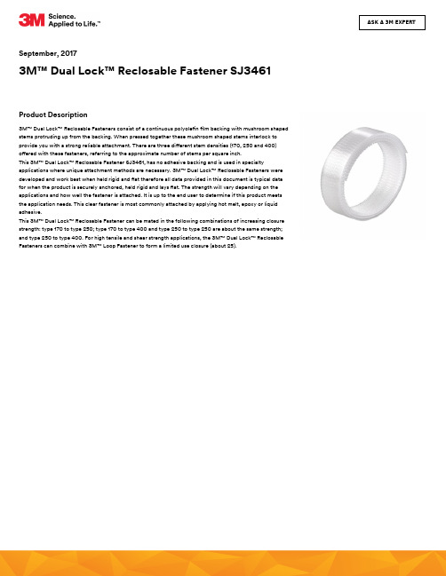
ASK A 3M EXPERTSeptember, 20173M™ Dual Lock™ Reclosable Fastener SJ3461Product Description3M™ Dual Lock™ Reclosable Fasteners consist of a continuous polyole n lm backing with mushroom shapedstems protruding up from the backing. When pressed together these mushroom shaped stems interlock toprovide you with a strong reliable attachment. There are three di erent stem densities (170, 250 and 400)o ered with these fasteners, referring to the approximate number of stems per square inch.This 3M™ Dual Lock™ Reclosable Fastener SJ3461, has no adhesive backing and is used in specialtyapplications where unique attachment methods are necessary. 3M™ Dual Lock™ Reclosable Fasteners weredeveloped and work best when held rigid and at therefore all data provided in this document is typical datafor when the product is securely anchored, held rigid and lays at. The strength will vary depending on theapplications and how well the fastener is attached. It is up to the end user to determine if this product meetsthe application needs. This clear fastener is most commonly attached by applying hot melt, epoxy or liquidadhesive.This 3M™ Dual Lock™ Reclosable Fastener can be mated in the following combinations of increasing closurestrength: type 170 to type 250; type 170 to type 400 and type 250 to type 250 are about the same strength;and type 250 to type 400. For high tensile and shear strength applications, the 3M™ Dual Lock™ ReclosableFasteners can combine with 3M™ Loop Fastener to form a limited use closure (about 25).General InformationThis product is used for alternative attachment methods it requires a unique attachment method and, based on how this product is used, the heat resistance, tensile and shear strength can vary. This product does not have adhesive backing, so there is no release liner.Product Family: Plain backed for hot melt, liquid adhesive or other forms of attachment.These are typical values which were gathered from testing the PSA backed materials. Similar values can be expected when the Dual Lock is held securely in a rigid fashion, however the data may vary depending on the attachment method used.Technical Information NoteThe following technical information and data should be considered representative or typical only and should not be used for speci cation purposes.Typical Physical PropertiesProperty ValuesDual Lock Color ClearThickness Tolerance± 10 %Stems62 Stems/cm²400 Stems/in²Material Polyole n blendThickness Test Condition2.57 mm101 mil Unmated3.86 mm152 mil EngagedProperty: ThicknessTypical Performance CharacteristicsStatic Tensile Test Condition10,000 min Room Temperature10,000 min38°C (100°F)/100% R.H.10,000 min104°C (220°F)/100%R.H.Property: Static Tensilenotes: All combinations hold minimum 1000 grams/in² for indicated time and temperatureStatic Shear Test Condition10,000 min Room Temperature10,000 min38°C (100°F )/100% R.H.10,000 min104°C (220°F)/100%R.H.Property: Static Shearnotes: All combinations hold minimum 750 grams/in² for indicated time and temperatureDynamic Tensile (Engage)Substrate9 N/cm²13 lb/in²Type 170 to 25014.5 N/cm²21 lb/in²Type 170 to 40015 N/cm²22 lb/in²Type 250 to 250 22 N/cm²31 lb/in²Type 250 to 400 Property: Dynamic Tensile (Engage)Dynamic Tensile (Disengage)Substrate19 N/cm²27 lb/in²Type 170 to 250 30 N/cm²43 lb/in²Type 170 to 400 30 N/cm²43 lb/in²Type 250 to 250 42 N/cm²60 lb/in²Type 250 to 400 Property: Dynamic Tensile (Disengage)Dynamic Shear Substrate9.8 N/cm²14 lb/in²Type 170 to 25014.5 N/cm²21 lb/in²Type 170 to 40015 N/cm²22 lb/in²Type 250 to 250 41.3 N/cm²59 lb/in²Type 250 to 400 Property: Dynamic Shearnotes: 1" x 1" overlap; Rigid to Rigid substratesCleavage Strength Substrate21 N/cm width12 lb/in width Type 170 to 250 42 N/cm width24 lb/in width Type 170 to 400 42 N/cm width24 lb/in width Type 250 to 250 63 N/cm width35 lb/in width Type 250 to 400Property: Cleavage Strengthnotes: Rigid to Rigid, 2.25in longCycle Life Substrate1000Type 170 to 2501000Type 170 to 4001000Type 250 to 2501000Type 250 to 400Property: Cycle Lifenotes: Number of closures before losing 50% of original strengthFamily GroupNoteThe following technical information and data is intended as a guideline to assist customers in selecting 3M™ Dual Lock™ Reclosable Fasteners for further evaluation. This technical information is not product release speci cations or standards.All of these tests were performed on 3M™ Dual Lock™ Reclosable Fasteners which was well anchored, held rigid and laid at. Flexible applications can expect di erent results.Note: Unless stated di erently, the typical system performance and product properties were obtained using speci c test methods under controlled laboratoryconditions of 72°F ± 5°F and 50% ± 10% relative humidity. The user is responsible for evaluating 3M™Dual Lock™ Reclosable Fasteners under expected use conditions to ensure suitable performance for the intended application.Design ConsiderationsThe following information is intended to assist the designer considering the use of 3M™ Dual Lock™ Reclosable Fasteners. Product performance depends upon a number of factors, including the 3M™ Dual Lock™ Reclosable Fastener selected, themanner in which reclosable fastener is attached, and the time and environment in which it is expected to perform.Because many of these factors are uniquely within the user’s knowledge and control, it is required that the user evaluate 3M products to determine whether it is t for a particular purpose and suitable for the users substrates, method of application and desired end use.It is suggested that 4 square inches of 3M™ Dual Lock™ Reclosable Fasteners per 1 pound of static load be used as a starting point when determining how much 3M™ Dual Lock™ Reclosable Fasteners to use on any particular application. The amounts may be adjusted up or down depending on the needs of the speci c applications.Typical Environmental Performance Chemical and Environmental ExposureTo Chemicals: The polyole n backing stems and mushroom top should resist attack by most common solvents and alkaline solutions.To Environmental Exposure: Temperatures between -20°F (-29°C) and and 220°F (104°C) should have minimal e ect on closure strength. To maintain performance when exposed for extended periods to sunlight or ultraviolet radiation these products should be placed between two opaque or UV resistant surfaces. Speci c testing under the expected environmental conditions is recommended.To Water or Humidity: Closure strength should not be a ected by prolonged exposure to water or humidity.Storage and Shelf LifeStore under normal conditions of 70°F (21°C) and 50% R.H.To obtain best performance, use this product within 24 months from date of manufacture.SJ3460SJ3461Thickness (mm) Test Condition: Unmated2.572.57Thickness (mm) Test Condition: Engaged 3.86 3.86MaterialPolyole n blend Polyole n blendReferencesISO StatementTechnical InformationProduct UseWarranty, Limited Remedy, and Disclaimer Limitation of LiabilityIndustrial Adhesives and Tapes Division 3M CenterSt. Paul, MN 55144-1000800-362-3550 Please recycle.© 3M 2018. All Rights Reserved.The brands listed above are trademarks of 3M.1. Product PageUrl: https:///3M/en_US/company-us/all-3m-products/~/3M-Dual-Lock-Reclosable-Fastener-SJ3461?N=5002385+3293242291&rt=rud2. Safety Data SheetUrl: https:///3M/en_US/company-us/SDS-search/results/?gsaAction=msdsSRA&msdsLocale=en_US&co=ptn&q=SJ3461This Industrial Adhesives and Tapes Division product was manufactured under a 3M quality system registered to ISO 9001 and ISO/TS 16949 standardsThe technical information, guidance, and other statements contained in this document or otherwise provided by 3M are based upon records, tests, or experience that 3M believes to be reliable, but the accuracy, completeness, and representative nature of such information is not guaranteed. Such information is intended for people with knowledge and technical skills su cient to assess and apply their own informed judgment to the information. No license under any 3M or third party intellectual property rights is granted or implied with this information.Many factors beyond 3M’s control and uniquely within user’s knowledge and control can a ect the use and performance of a 3M product in a particular application. As a result, customer is solely responsible for evaluating the product and determining whether it is appropriate and suitable for customer’s application, including conducting a workplace hazard assessment and reviewing all applicable regulations and standards (e.g., OSHA, ANSI, etc.). Failure to properly evaluate, select, and use a 3M product and appropriate safety products, or to meet all applicable safety regulations, may result in injury, sickness, death, and/or harm to property.Unless a di erent warranty is speci cally stated on the applicable 3M product packaging or product literature (in which case such warranty governs), 3M warrants that each 3M product meets the applicable 3M product speci cation at the time 3M ships the product. 3M MAKES NO OTHER WARRANTIES OR CONDITIONS, EXPRESS OR IMPLIED, INCLUDING, BUT NOT LIMITED TO, ANY IMPLIED WARRANTY OR CONDITION OF MERCHANTABILITY, FITNESS FOR A PARTICULAR PURPOSE, OR ARISING OUT OF A COURSE OF DEALING, CUSTOM, OR USAGE OF TRADE. If a 3M product does not conform to this warranty, then the sole and exclusive remedy is, at 3M’s option, replacement of the 3M product or refund of the purchase price.Except for the limited remedy stated above, and except to the extent prohibited by law, 3M will not be liable for any loss or damage arising from or related to the 3M product, whether direct, indirect, special, incidental, or consequential (including, but not limited to, lost pro ts or business opportunity), regardless of the legal or equitable theory asserted, including, but not limited to, warranty, contract, negligence, or strict liability.。
3M Dual Lock 重组可重复锁定快速连接SJ3550产品说明说明书

ASK A 3M EXPERTJune, 20143M™ Dual Lock™ Reclosable Fastener SJ3550Product Description3M™ Dual Lock™ Reclosable Fasteners are positive locking, hidden fasteners designed for use in a variety ofattachment solutions. They consist of continuous strips of polyole n stems with a mushroom shaped topprotruding up from the backing. When snapped together the mushroom shaped caps interlock producing astrong reliable Fastener.The standard Dual Lock fasteners are available in three di erent stem densities (170, 250 and 400) referring tothe approximate number of stems per square inch. (26, 39, 62 stems per square centimeter) By inter-lockingdi erent stem density combinations you can create the strength that suits your application; more total stemsgive higher strength. The Dual Lock Reclosable fasteners can be mated in the following combinations ofincreasing closure strength: Type 170 to Type 250, Type 170 to Type 400, Type 250 to Type 250 and Type250 to Type 400. We do not recommend using the Type 170 to 170 because it does not have enough strengthfor a good connection. We do not recommend using the Type 400 to 400 because it is too strong and maycause stems and heads to rip out rendering the fastener no longer reclosable.The Dual Lock Low Pro le has one stem density of approximately 705 stems per square inch and theyinterlock to themselves. The low pro le products are not intended to mate to the standard size Dual Lock.There are a variety of pressure sensitive adhesives available with Dual Lock to cover most application needs.The pressure sensitive adhesive makes the Dual Lock easy to use, simply remove the liner, place the Dual Lockand apply rm consistent pressure to assure good contact with the substrate you are adhering. We also o ernon-adhesive backed Dual Lock for applications where the PSA does not meet your needs.Product Features•Easy Alignment: Dual Lock fasteners engage in any direction or position. The mushroom stems slide intoposition until they are engaged by snapping together applying rm pressure, this eliminates concerns aboutmisalignment or spontaneous engagement.•Positive Locking: Dual Lock fasteners engage/fasten with an audible snap and detectable movement assuringcomplete and secure closure.•Reclosability: Dual Lock fasteners can be opened and closed for multiple closure applications (high cyclelife).•Blind Attachment: Dual Lock fasteners can be attached on the backside of substrate (i.e. trim piece) where itwill not interrupt the show surface.•Rattle-Free: Dual Lock fasteners will not rattle loose.•Ease of Assembly: Dual Lock fasteners can be used to attach components before they enter the nalassembly plant, reducing the number of parts and the assembly time. No tools are required.•Adjustable Strength: By selecting di erent combinations of the various stem densities of the Dual Lock thefastener can be designed to meet the strength needs of the designer.•Product Forms: Dual Lock fasteners come in a variety of forms: Backed with Pressure Sensitive adhesive,Non-woven, Rigid backed, Die Cut Shapes, and low pro le.•Attachment Methods: The wide varieties of Dual Lock fasteners allow a design engineer exibility to be ableuse and attach Dual Lock to just about any substrate or application. Peel and stick pressure sensitive adhesivebacked is quick and easy yet strong and secure. Non-woven backed can be used with a variety of adhesivechoices such as hot melt, liquid, epoxies, sealants, etc. We have parts that can be attached with a screw orrivet; rigid and plain backed for developing your own special device.General InformationPressure Senstive Adhesive backed productProduct Family: Acrylic PSA VHB conformable type backing for medium to high surface energy attachmentTechnical Information NoteThe following technical information and data should be considered representative or typical only and should not be used for speci cation purposes.Typical Physical PropertiesProperty Values Dual Lock Color Black Adhesive Color White Thickness3.51 mm 138 mil Engaged to itself or to one of the same family 5.74 mm 226 mil Stems 39 Stems/cm²250 Stems/in²Liner Material Silicone treated Polyole n with Red printing Liner Thickness 0.1 mm 4 mil Liner ColorClearTypical Performance CharacteristicsPropertyValues Temperature Resistance93 °C200 °FDynamic Tensile (Engage)Substrate 9 N/cm²13 lb/in²Type 170 to 25014.5 N/cm²21 lb/in²Type 170 to 40015.2 N/cm²22 lb/in²Type 250 to 25021.4 N/cm²31 lb/in²Type 250 to 40018.5 N/cm²27 lb/in²Low Pro le to Low Pro leProperty: Dynamic Tensile (Engage)Table continued on next pageDynamic Tensile (Disengage)Substrate 18.5 N/cm²27 lb/in²Type 170 to 25029.6 N/cm²43 lb/in²Type 170 to 40029.6 N/cm²43 lb/in²Type 250 to 250Dynamic Tensile (Disengage)Substrate41.4 N/cm²60 lb/in²Type 250 to 400 Property: Dynamic Tensile (Disengage)Dynamic Shear Substrate9.8 N/cm²14 lb/in²Type 170 to 25014.5 N/cm²21 lb/in²Type 170 to 40015 N/cm²22 lb/in²Type 250 to 250 41.3 N/cm²59 lb/in²Type 250 to 400 Property: Dynamic ShearCleavage Strength Substrate21 N/cm width12 lb/in width Type 170 to 250 35 N/cm width20 lb/in width Type 170 to 400 42 N/cm width24 lb/in width Type 250 to 250 56 N/cm width32 lb/in width Type 250 to 400 Property: Cleavage Strengthnotes: Rigid backed from Rigid backedT-Peel Adhesion Substrate1.2 N/cm width0.7 lb/in width Type 170 to 2502.5 N/cm width 1.4 lb/in width Type 170 to 4003.3 N/cm width 1.9 lb/in width Type 250 to 250 2.6 N/cm width 1.5 lb/in width Type 250 to 400Property: T-Peel Adhesionnotes: Flexible from Flexible90° Peel Adhesion Substrate3.2 N/cm width 1.8 lb/in width Type 170 to 250 5.4 N/cm width 3.1 lb/in width Type 170 to 400 8.1 N/cm width4.1 lb/in width Type 250 to 250 8.1 N/cm width 4.6 lb/in width Type 250 to 400Property: 90° Peel Adhesionnotes: Flexible from RigidCycle Life Substrate1000Type 170 to 2501000Type 170 to 4001000Type 250 to 2501000Type 250 to 400Property: Cycle Lifenotes: Number of closures before losing 50% of original strengthNoteThe following technical information and data is intended as a guideline to assist customers in selecting 3M™ Reclosable Fasteners for further evaluation. This technical information is not product release speci cations or standards. Unless stated di erently, the typical system performance and product properties were obtained using speci c test methods under controlled laboratory conditions of 72°F± 5°F and 50% ± 10% relative humidity. The user is responsible for evaluating 3M reclosable fasteners under expected use conditions to ensure suitable performance for the intended application.These are typical values which were gathered from testing the PSA backed materials. Similar values can be expected when the Dual Lock is held securely in a rigid fashion.Tests were run at 12 inches per minuteProduct Performance:Additional Informationnotes: This guide should assist you in determining which product will adhere best to your substrate for.Family GroupReferencesISO StatementTechnical InformationDesign Considerations• As a general rule, four square inches of fastener area per pound of static tensile or shear load to be supported is suggested as a starting point for evaluation. More or less area may be needed depending on speci c conditions or end use applications. Type 250 Dual Lock Reclosable fasteners less than 0.75" (19 mm) width should not be engaged to other type 250 Dual Lock Reclosable fastener as low disengagement values may occur.• Whenever possible design one side of the Dual Lock reclosable fasteners to be larger than the mating side. This will allow for variability or mismatch in Dual lock alignment positions, and ensure 100% fastening area contact. Another approach would be to design two rectangular shaped fastener pieces so that they can be engaged in a cross web/perpendicular pattern (crossed).• Dual Lock strength is proportional to the fastening contact area, and the number of stems in combination used. More stems and more Dual Lock used gives you more strength, less stems combined and using less Dual Lock will give you less strength.• Dual Lock disengagement strength/performance is strongest in direct tensile. Peel/cleavage mode is where it is most easily removed.• Final product performance depends upon a combination of factors: the substrate and its surface characteristics, the fastener selected, the application method and conditions, the time and environmental conditions required for the application. Because these factors are unique to each application, the user must evaluate Dual Lock and do any testing required to determine Dual Lock’s suitability for the user’s desired end use.Storage and Shelf LifeTo obtain best performance, use this product within 24 months from date of manufacture.SJ3550SJ3551SJ3552Thickness (mm) 3.513.513.51Liner MaterialSilicone treated Polyole n with Red printing Silicone treated Polyole n with Red printing Silicone treated Polyole n with Red printing Liner Thickness (mm)0.10.10.1Liner ColorClearClearClear1. Product PageUrl: https:///3M/en_US/company-us/all-3m-products/~/3M-Dual-Lock-Reclosable-Fastener-SJ3550?N=5002385+3293242274&rt=rud 2. Safety Data SheetUrl: https:///3M/en_US/company-us/SDS-search/results/?gsaAction=msdsSRA&msdsLocale=en_US&co=ptn&q=SJ3550This Industrial Adhesives and Tapes Division product was manufactured under a 3M quality system registered to ISO 9001 standards.The technical information, recommendations and other statements contained in this document are based upon tests or experience that 3M believes are reliable, but the accuracy or completeness of such information is not guaranteed.Product UseWarranty, Limited Remedy, and Disclaimer Limitation of LiabilityIndustrial Adhesives and Tapes Division 3M CenterSt. Paul, MN 55144-1000800-362-3550 Please recycle.© 3M 2018. All Rights Reserved.The brands listed above are trademarks of 3M.Many factors beyond 3M’s control and uniquely within user’s knowledge and control can a ect the use and performance of a 3M product in a particular application. Given the variety of factors that can a ect the use and performance of a 3M product, user is solely responsible for evaluating the 3M product and determining whether it is t for a particular purpose and suitable for user’s method of application.Unless an additional warranty is speci cally stated on the applicable 3M product packaging or product literature, 3M warrants that each 3M product meets the applicable 3M product speci cation at the time 3M ships the product. 3M MAKES NO OTHER WARRANTIES OR CONDITIONS, EXPRESS OR IMPLIED, INCLUDING, BUT NOT LIMITED TO, ANY IMPLIED WARRANTY OR CONDITION OF MERCHANTABILITY OR FITNESS FOR A PARTICULAR PURPOSE OR ANY IMPLIED WARRANTY OR CONDITION ARISING OUT OF A COURSE OF DEALING, CUSTOM OR USAGE OF TRADE. If the 3M product does not conform to this warranty, then the sole and exclusive remedy is, at 3M’s option, replacement of the 3M product or refund of the purchase price.Except where prohibited by law, 3M will not be liable for any loss or damage arising from the 3M product, whether direct, indirect, special, incidental or consequential, regardless of the legal theory asserted, including warranty, contract, negligence or strict liability.。
密尔沃基 M12 FIR38LR 3 8英寸延长臂棘轮 使用说明书
PERSONAL SAFETY
•Keep handles and grasping surfaces dry, clean
•Stay alert, watch what you are doing and use common sense when operating a power tool. Do not use a power tool while you are tired or under
tools allow you to become complacent and ignore tool safety principles. A careless action can cause severe injury within a fraction of a second.
POWER TOOL USE AND CARE
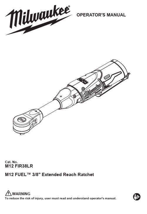
OPERATOR'S MANUAL
Cat. No.
M12 FIR38LR M12 FUEL™ 3/8" Extended Reach Ratchet
WARNING
To reduce the risk of injury, user must read and understand operator's manual.
battery packs. Use of any other battery packs may
•Prevent unintentional starting. Ensure the switch is in the off-position before connecting to power source and/or battery pack, picking up or carrying the tool. switch or energising power tools that have the switch on invil and grease. Slippery handles and grasping surfaces do not allow for safe handling and control of the tool in unexpected situations.
第三章 紧固件FASTENERS
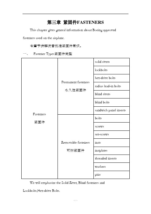
第三章紧固件FASTENERS This chapter gives general information about Boeing approved fasteners used on the airplane.本章节讲解波音批准紧固件常识。
一、Fastener Types紧固件类型We will emphasize the Solid Rivet, Blind fasteners and Lockbolts,Hex-drive Bolts.我们将着重了解固杆铆钉,盲紧固件,锁螺栓,Hi-Lok。
1.Solid Rivets固杆铆钉(1)Most of the fasteners used on this airplane are solid-shank rivetsmade from specified aluminum alloys. Solid rivets are permanentfasteners that are used where rivets must have sufficient shearstrength and where complete hole-filling is important.飞机上应用的紧固件大部分是铝合金制的固杆铆钉。
作为一种永久性紧固件,必须有足够的剪切强度并且能完全塞满铆钉孔。
(2)You can use softer alloy rivets as alternative fasteners for the usualrivets in some locations.A larger number of fasteners or a largerdiameter of fastener can be necessary to get the same structuralstrength. Make sure the material edge margin and fastener spacingare correct when you use softer alloy rivets as alternative fasteners.在一些位置可以使用软合金的铆钉替代一般铆钉,有必要使用大量的紧固件或者大直径紧固件以达到同等结构强度,并保证紧固件的边距和间距正确。
防振产品指南说明书

APPLICATION GUIDE Updated: Friday, July 16th 2021 A Guide To Anti-Vibration Products for FastenersContentsWhat we testedWashersAdhesivesNylon locking patchesMethodologyPerformance criteriaResultsSplit washersNordlock washersLoctite 248 adhesive (withLoctite 7088 primer)Loctite 2760 adhesiveNylok-treated T-nutsZinc-plated fastenersPerformance comparisonchartRecommendationsIndustrial machines are often affected by vibration, which can loosen the threaded fasteners that hold joints together. To keep your machine’s joints tightly fitted together in such conditions, you need something that will prevent your fasteners from coming loose.So what’s the best solution? After testing six ways to protect fasteners from vibration, we found Nordlock washers and Loctite products to be the most effective.Keep reading to find out what products we tested, how we evaluated them, and how to find the right anti-vibration solution for you.What we testedWashers, adhesives, and locking patches are some of the most common ways to keep fasteners tight. We tested six of these products in search of the best anti-vibration solution:WashersSplit washersNordlock washersAdhesivesLoctite 248 with Loctite 7088 primerLoctite 2760Nylon locking patchesNylock-treated T-nutsZinc-plated fasteners with locking patchesMethodologyTo evaluate each solution, we conducted an accelerated vibration test. This means we subjected our test jig to vibrations with significantly higher frequency and amplitude than in standard operational environments. Any solution that performs well in our accelerated environment will be sure to meet the demands of real application scenarios!Performance criteriaWe want to make it easy for you to build the right products, so we put a lot of thought into which components we offer on our machine design platform. Fasteners are no exception. Here’s what we looked for with each solution:Rate at which the fasteners loosenedTotal number of loose fasteners (observed after the vibration test)How easy it was to useHow well it integrated with Vention’s other componentsResultsSplit washersVention First ReleaseThe split washer works in two ways: first, its spring shape helps maintain the fastener’s preload. Second, the sharp edge of the split washer digs into the parent material to prevent the fastener from unscrewing.This second function only works when the parent material is softer than the split washer, which is made of spring steel. For this reason, split washers won’t be effective in any application that uses steel as the joint’s parent material. You don’t have to worry about this with Vention joints, though. Our joints are made of 6061-T6 aluminum alloy, which is softer than any split washer.Split washer test results: Out of 66 fasteners, 4 came completely loose during the test, and an additional 22 fasteners were under spec post-test (but were not yet turning freely).Split washer conclusions: Split washers are a good anti-vibration method for Vention joints. The washers are able to dig into the parent material, build up a burr, and resist further loosening.Nordlock washersVention First ReleaseThe Nordlock washer is a two-piece wedge style washer. Each half of the washer has two serrated surfaces: fine serrations on the outside, and larger wedge-shaped serrations on the inside. The fine serrations dig into the parent material when the fastener is torqued. This prevents the washers from slipping against the bolt or joint’s surface.The broadly serrated inner surfaces prevent the fastener from unscrewing. Because of the wedges, any attempt to loosen the fastener will increase its preload before the washer is able to ratchet to the next set of wedges. Nordlock washers are an excellent choice of anti-vibration method.Nordlock washer test results: Out of 20 fasteners, none came completely loose during the test, and 14 fasteners were under spec post-test. Fourteen might seem like a lot, but it’s somewhat of a false positive; we believe the slight decrease in torque was caused by initial settling of the washers (the two parts of each washer fell into place better after the test began).Nordlock washer conclusions: The only drawback to these washers is that if your application features a counterbore, the fastener heads will protrude from it. Other than that, Nordlock washers are an excellent choice of anti-vibration method with extremely high vibration endurance.Loctite 248 adhesive (with Loctite 7088 primer)Vention First ReleaseLoctite, one of the most common anti-vibration methods, is an anaerobic adhesive that works by gluing the male and female threads together. It’s available in many different strengths, from light to permanent. Loctite 248 is a medium-strength adhesive that comes in a convenient stick format. The manufacturer recommends using it with the Loctite 7088 primer.Loctite 248 adhesive + primer results (9-hour curing period): Out of 25 fasteners, 7 came loose during the test (although none were completely loose), and 6 were under spec post-test.Loctite 248 adhesive + primer conclusions: Loctite 248 is better than nothing, but it’s not as good as the other methods we tested. Plus, cleaning the threads, applying the primer and glue, and waiting for it to dry was inconvenient.Loctite 2760 adhesiveVention First ReleaseLoctite 2760 is a liquid anaerobic adhesive with a high locking strength. The adhesive cures in the threads between the fastener and T-nut to create a glued connection between them. Loctite 2760 cures fully in 24 hours without the use of an activator, but we prepared this test on a Friday and ran it on the following Monday night, which gave it a full 72 hours of cure time.Overall, Loctite 2760 performed very well, with only 2 fasteners coming loose during the test and an additional 6 found under spec post-test. Loctite 2760 is the best product so far in terms of the total number of fasteners under spec (in our post-test observations).Loctite 2760 adhesive (72-hour curing period): Out of 30 fasteners, 2 came loose during the test (although none were completely loose), and 6 were under spec post-test.Loctite 2760 adhesive conclusions: Loctite 2760 had the best overall performance out of any method we tested. However, that might not be enough to justify the time it takes to clean the fasteners and apply it, given that Nordlock washers are almost as good and much more convenient.Nylok-treated T-nutsVention First ReleaseThese specialty T-nuts are just standard Vention T-nuts with locking patches applied to the threads. We tested two types: some with half of the thread treated, and others with the full thread treatment.Unfortunately, neither type performed well. The Nylok patch adds so much resistance when installing a fastener that the T-nut twists and misaligns with the extrusion T-slot. To fix the misalignment problem, we had to tighten and loosen the fastener while wiggling the T-nut into position.There are two problems here. First, all this wiggling means you might wear out the Nylok patch before you can even run a test. Second, it’s way too easy to get the T-nut misaligned. If you don’t carefully check and fix these misalignments before starting your application, the vibrations will cause the T-nut to realign itself. When it finally pops into the correct location, the bolt will lose all pre-tensioning.Nylok-treated T-nut test results: Out of 20 fasteners (10 half-treated and 10 full-treated), 14 came completely loose during the test, and all 20 were under spec post-test.Nylok-treated T-nut conclusions: Overall, Nylok-treated T-nuts are a poor choice of anti-vibration method. With 100% of the sample fasteners under spec post-test, need we say more?Zinc-plated fastenersVention First ReleaseTo measure the performance of zinc-plated fasteners, we had to conduct two tests: one of bare zinc-plated fasteners, and one with a locking patch on the zinc-plated fasteners. This allowed us to isolate the two variables (the first being the change in surface treatment from black-oxide to zinc, and the secondbeing whether or not there was a locking patch).Both types of zinc plated fasteners performed extremely poorly in the vibration testing. This is likely due to the reduction in friction coefficient caused by the zinc plating.These locking patches behaved similarly to those used in the Nylok-treated T-nuts. They were likewise difficult to install, and the locking patch caused the T-nut to rotate. Even with a full locking patch, the zinc-plated fasteners failed to match the performance of the standard black oxide baseline. It should be noted that the plain black zinc test had to be stopped 5 minutes early because the jig became too loose to continue the test.Bare zinc-plated fastener test results: Out of 31 fasteners, 18 came completely loose during the test, and 20 were under spec post-test.Zinc-plated fastener with full locking patch test results: Out of 36 fasteners, 11 came completely loose during the test, and 25 were under spec post-test. Zinc-plated fastener conclusions: Overall, zinc-plated fasteners are a poor choice of anti-vibration method—even with the locking patch, their performance was worse than the black oxide baseline.Performance comparison chartVention First ReleaseThe chart shows the performance of each product tested relative to plain black zinc fasteners. The number above the bar represents the performance factor. For example, the standard black oxide fasteners used by Vention are 4.9 times better performing than plain black zinc. Likewise, Loctite 2760 or Nordlock could be used to achieve performance factors of 50 and 94 times better than plain black zinc for high vibration environments. RecommendationsWe found that the most effective anti-vibration solutions are anaerobic adhesives and mechanical washers.Overall, Nordlock washers were extremely effective. They’re as easy to install as any standard washer—and easier to install than the next-best contender, the Loctite 2760 adhesive. The drawback of Nordlock washers is that the fastener heads protrude above the part surface when installed in counterbores.If you can’t use Nordlock washers—because your application includes counterbores, and fastener head protrusion is unacceptable—adhesives are a great alternative. Out of the two glues we tested, Loctite 2760 was easiest to use (because it did not require any primer) and performed best. Just remember that fasteners used with Loctite 2760 must be free of contaminants.The bottom line: Nordlock washers and Loctite 2760 adhesive are our top picks, each with some advantages over the other depending on application.。
我要看拉链的作文英语
我要看拉链的作文英语英文回答:A zipper is a type of mechanical fastener that consists of two rows of interlocking teeth, one row on each side of a fabric tape. The teeth are typically made of metal or plastic, and they are designed to mesh together when the zipper is closed. Zippers are used to open and close clothing, bags, and other items, and they come in a variety of sizes and styles.The first zipper was invented in 1893 by Whitcomb Judson, an American engineer. However, Judson's zipper was not very practical, and it was not until 1913 that Gideon Sundback, a Swedish-born American engineer, invented the modern zipper. Sundback's zipper was much more reliable than Judson's, and it quickly became the standard type of zipper used around the world.Zippers are made up of several different components,including:Teeth: The teeth are the interlocking parts of the zipper that hold it together. Teeth can be made of metal or plastic, and they come in a variety of shapes and sizes.Slider: The slider is the part of the zipper that moves up and down to open and close it. Sliders can be made of metal or plastic, and they may have different features, such as a pull tab or a lock.Tape: The tape is the fabric material that the teeth are attached to. Tapes can be made of a variety of materials, such as cotton, polyester, or nylon.Zippers are used in a wide variety of applications, including:Clothing: Zippers are used to open and close clothing items, such as jackets, pants, and dresses.Bags: Zippers are used to open and close bags, such asbackpacks, suitcases, and purses.Other items: Zippers are also used in a variety ofother items, such as tents, sleeping bags, and furniture.Zippers are a versatile and convenient type of fastener, and they are used in a wide range of applications. They are easy to use and they can be used to open and close items quickly and easily.中文回答:拉链是一种由两排相互交错的齿组成的机械紧固件,每排齿位于织带的两侧。
材料力学本科生专业英语6--fasteners-王向峰

钉牢,系牢
Resilient
紧固件
Resilience
螺丝
Slot
螺栓
Slotted nut
螺帽
Jam
轴,柄
Clampຫໍສະໝຸດ 垫片Dissimilar
可去掉的
Sheet metal
拆开,使分离
Blind
开口销
Recess
装配,组装
Panel
装配(名词)
Hexagonal
拆卸,拆开
Knurl
焊接
Knurling
➢ the top threads for the self-locking nut are manufactured at
a reduced pitch diameter
• 自锁螺母顶部螺纹用减少的节圆直径被制造 顶部螺纹的节圆直径减少
自锁螺母
➢ 意为:... 使用减小顶部螺纹节圆直径的自锁螺母
During assembly, they clamp(夹紧)the threads of the bolt and produce greater frictional forces than an ordinary nut does.
off.
➢ a door rattle ( rattlen. 喋喋不休的人;格格声) ➢ a wheel coming off
车轮脱落
Such possibilities must be taken into account in the selection of the type of fastener for the specific application.
➢ literally adv. 1. 照字义地,照着原文;逐字地 2. 实际地,实在地,确实地,准确地,不加夸张地 ➢ the total product 整个产品
COOLER CART操作手册说明书
Operator’s ManualSave for future referenceDate PurchasedCode: (ex: 10859)Serial:(ex: U1060512345)For use with machines having Code Numbers:10808, 11068, 11849Register your machine: /registerAuthorized Service and Distributor Locator: /locatorSAFETYPage Installation.......................................................................................................................Section A Technical Specifications.......................................................................................................A-1 Safety Precautions...............................................................................................................A-2 Unpacking.....................................................................................................................A-2Filling Coolant Reservoir...............................................................................................A-2Coolant Connections.....................................................................................................A-3Input Power Connection................................................................................................A-4 Assembly of Precision Tig....................................................................................................A-4 Fastener Quick Reference............................................................................................A-5Connection of Tig Torches............................................................................................A-5 ________________________________________________________________________________ Operation.........................................................................................................................Section B Safety Precautions...............................................................................................................B-1 General Description......................................................................................................B-1Recommended Processes............................................................................................B-1Recommended Equipment............................................................................................B-1Turning the System On.................................................................................................B-2Cooling Efficiency..........................................................................................................B-2 ________________________________________________________________________________ Maintenance....................................................................................................Section D Safety Precautions................................................................................................D-1 Routine ...........................................................................................................D-1Periodic...........................................................................................................D-1Pump...............................................................................................................D-1Pump Motor....................................................................................................D-1Heat Exchanger..............................................................................................D-1Reservoir Coolant Level..................................................................................D-2Coolant Treatment Recommendation......................................................D-2,D-3Pump Inlet Filter..............................................................................................D-3Procedure.......................................................................................................D-3Additional Service Notes.................................................................................D-4 ________________________________________________________________________Troubleshooting..............................................................................................Section E Safety Precautions.................................................................................................E-1 How to Use Troubleshooting Guide.......................................................................E-1 Troubleshooting Guide..........................................................................................E-2 ________________________________________________________________________Diagrams..........................................................................................................Section F Wiring Diagram......................................................................................................F-1 Flow Diagram.........................................................................................................F-2 Dimension Print......................................................................................................F-3 ________________________________________________________________________Parts List.................................................................................................................P-402 ________________________________________________________________________Save the instruction manual and service directory sup-plied with the Under-Cooler cart for parts orders and future maintenance service.FILLING COOLANT RESERVOIR(See Section A-1 for recommended coolant.)To avoid freeze damage and water leakage in ship-ment, the Under-Cooler cart is delivered empty with no coolant in the system. To fill the unit, locate the plastic reservoir fill cap at the front middle of the cool-er drawer.Clean tap water, distilled water, de-ionized water, a 50/50 mix of pure ethylene glycol and water can be added into the coolant reservoir. The reservoir fill hole mates with most coolant containers but, to avoid spillage of coolant, a funnel should be placed into the reservoir hole when filling.NOTE: Pure solutions and mixtures of, or materials (i.e. towels) wetted with ethylene glycol are toxic to humans and animals. They must not be haphazardly discarded, especially by pouring liquids down the drain. Contact the local EPA office for responsible dis-posal methods or for recycling information.For best results when using the Under-Cooler cart with Lincoln torches, use distilled or de-ionized water,although if not available, tap water can be used. If pro-tection from freezing is desired, use a 50% water and 50% pure ethylene glycol mixture and should be ordered from a local welding distributor.When using the Under-Cooler cart, DO NOT USE OIL BASED COOLANTS OR COOLANTS THAT CONTAIN RUST INHIBITORS OR LEAK STOP-PERS.When adding coolant to the Under-Cooler cart,UNPLUG THE COOLER BEF ORE F ILLING THE COOLANT RESERVOIR:-----------------------------------------------------------------------ADDING COOLANT:Carefully add 2 gallons (7.6 liters) of coolant through a funnel into the coolant reservoir fill hole.AVOID SPILLING COOLANT INTO THE DRAWER OR ONTO THE PUMP MOTOR.If you have hose to make replacement hose assem-blies but need to order the fittings and hardware, seebelow for the correct part numbers to mate with theUnder-Cooler cart and the Precision TIG Machine.Then follow the given instructions.(2) T15007-2 Connector Nuts(2) T15008 Nipples for 3/16" I.D. hose(2) S10888-35 Hose ClampsRemove the connector nut from the INLET hose bymaking a straight cut 1/4"-1/2" (6-12mm) away fromthe end of the nipple located inside of the hose. Takethe nipple and the connector nut ordered above andinsert the nipple into the connector nut so that thethreaded end of the connector nut points away fromthe barbed end of the nipple. Twist the barbed end ofthe nipple into the hose until the shoulder of the nippleis flush with the end of the hose. Secure the hose ontothe nipple with the hose clamp to insure that the con-nection is watertight. No water can leak from the con-nection if it is properly attached. Repeat the procedurefor the OUTLET hose. When complete, follow the con-nection procedure detailed above for connecting thehoses to the cooler drawer fittings.*The connector and nipple listed fit tightly onto 5/32"(4.0mm) to 3/16" (4.8mm) inner diameter hose, but ifclamped tightly to the hose, can fit up to a .25(6.4mm) inner diameter hose.NOTE: Hoses have been provided with this productand any replacement hoses, purchased or made,should not deviate from their length. To replace the-ses hoses from Lincoln Electric ORDER (1) S18453-IN19 (HOT)AND (1) S18453-20 (COLD). Hoses toolong may be pinched when replacing the gas bottlesand hoses too short may be damaged opening thecooler drawer.COOLANTCOOLING EFFICIENCYThe high cooling efficiency of the Under-Cooler cart offers a cooler, more comfortable weld than conven-tional air-cooled procedures as well as leading com-petitors water cooled systems.The Under-Cooler cart effectively removes the heat of the arc away from the torch handle and places it into the exiting air flow at the back of the Cooler. Ambient air temperature affects the coolant temperature of the cooler.Unlike other water coolers that depend on bulky reser-voir size, the high efficiency components of the Under-Cooler cart allows the reservoir size to be small. The result is a lightweight unit, in a drawer with additional storage space for welding accessories.Service the pumpʼs inlet strainer:a. Place absorbent towels underneath pump head toprevent stray coolant from wetting coolerʼs electrical components.b. Hold pump head to apply counter torque when loos-ening strainers 7/8 acorn nut. Do not confuse with 3/4 acorn nut. Remove nut and slide inlet strainer down and out from pump head. See figure 3A.c. Inspect strainer for damage or excessive clogging:• Replace or Gently rinse strainer under running water to thoroughly clean itd. Use a mirror to inspect inside of pump for contami-nation. If hardened debris is present and interferes with filter seating, carefully remove it with dental pick without scratching inside of the pump. Use care not to drop debris into pump.e. Reinstall strainer and acorn nut, tighten to 75 in-lbs.(8.5N-m) of torque. Hold pump head to apply counter-torque when loosening strainers 7/8 acorn nut.f. Wipe dry all areas wetted by coolant. Dispose of towels in an environmentally responsible manner. Add coolant:• Add 2 Gal. ( 7.6 ltrs.) of coolant, either the recom-mendations off the water cooled accessory or if none, see the design specification summary listed in this manual.ADDITIONAL SERVICE NOTES:• Always use a back-up wrench on pump head when loosening or tightening pump fittings.• Never run the pump dry. Always use a recommend-ed coolant, otherwise pump damage may result.• F lush coolant from system and replace with fresh, recommended coolant at least once a year. More frequent flushing may be necessary, depending upon the userʼs particular system or its usage, especially if it is prone to clogging from biological growth in the coolant.This Troubleshooting Guide is provided to help you locate and repair possible machine malfunctions.Simply follow the three-step procedure listed below.Step 1.LOCATE PROBLEM (SYMPTOM).Look under the column labeled “PROBLEM (SYMP-TOMS)”. This column describes possible symptoms that the machine may exhibit. Find the listing that best describes the symptom that the machine is exhibiting.Step 2.POSSIBLE CAUSE.The second column labeled “POSSIBLE CAUSE” lists the obvious external possibilities that may contributeto the machine symptom.Step 3.RECOMMENDED COURSE OF ACTIONThis column provides a course of action for the Possible Cause, generally it states to contact your local Lincoln Authorized Field Service Facility.If you do not understand or are unable to perform the Recommended Course of Action safely, contact your local Lincoln Authorized Field Service Facility.HOW TO USE TROUBLESHOOTING GUIDEService and Repair should only be performed by Lincoln Electric Factory Trained Personnel.Unauthorized repairs performed on this equipment may result in danger to the technician and machine operator and will invalidate your factory warranty. For your safety and to avoid Electrical Shock, please observe all safety notes and precautions detailed throughout this manual.__________________________________________________________________________V 5 1 1JapaneseChineseKoreanArabicLEIA E COMPREENDA AS INSTRUÇÕES DO FABRICANTE PARA ESTE EQUIPAMENTO E AS PARTES DE USO, E SIGA AS PRÁTICAS DE SEGURANÇA DO EMPREGADOR.JapaneseChineseKoreanArabicREAD AND UNDERSTAND THE MANUFACTURER’S INSTRUCTION FOR THIS EQUIPMENT AND THE CONSUMABLES TO BE USED AND FOLLOW YOUR EMPLOYER’S SAFETY PRACTICES.SE RECOMIENDA LEER Y ENTENDER LAS INSTRUCCIONES DEL FABRICANTE PARA EL USO DE ESTE EQUIPO Y LOS CONSUMIBLES QUE VA A UTILIZAR, SIGA LAS MEDIDAS DE SEGURIDAD DE SU SUPERVISOR.LISEZ ET COMPRENEZ LES INSTRUCTIONS DU FABRICANT EN CE QUI REGARDE CET EQUIPMENT ET LES PRODUITS A ETRE EMPLOYES ET SUIVEZ LES PROCEDURES DE SECURITE DE VOTRE EMPLOYEUR.LESEN SIE UND BEFOLGEN SIE DIE BETRIEBSANLEITUNG DER ANLAGE UND DEN ELEKTRODENEINSATZ DES HER-STELLERS. DIE UNFALLVERHÜTUNGSVORSCHRIFTEN DES ARBEITGEBERS SIND EBENFALLS ZU BEACHTEN.。
拧紧基础知识讲解

“Snug”
Torque“
事宜扭矩
Residual Torque Measured Dynamically残余扭矩的动态测量
Capture Angle 2° - 4°角度
Angle, q
工件连接基础知识
Hard Joint - 30° or less - high torque rate
硬连接——30°或更小——高转矩率
扭矩测量
“标记法 Back-to-the-Mark”
准确度
:高
方便性/速度 : 低
Mark then loosen Bolt. Tighten Back to Original Position标记后柠松螺栓,再拧紧回初始位置。
Truly Checks Dynamic Tightening Torque切切实实的检查动态
Control
峰顶扭矩测量应用在用扭力工具进行紧固件安装中----这是统计过程控制最恰当最精确的测量方法。
静态扭矩
- Torque Value That Exist Without Producing Rotation in a Fastener - Used Only as an Indication of a Minimum Torque
紧固件和 驱动类型
Operator Ergonomics
(Reaction, Tool Weight, Arm Position, Frequency)
人机工程学 的应用(反 应,工具重 量,力臂位 置,频率)
拧紧工具选择综述
螺栓连接的可靠性影响因素很多:
Reliable bolted joints are dependent on many factors:
汽车发动机飞轮寿命检测手册说明书
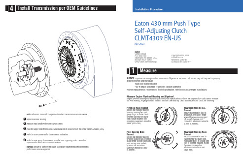
Measure Engine Flywheel Housing and FlywheelEngine flywheel housing and flywheel must meet these specifications or there will be premature clutch wear. Remove old Pilot Bearing. All gauge contact surfaces must be clean and dry. Use a dial indicator and check the following:Flywheel Face RunoutSecure dial indicator base to flywheel housing face. Put gauge finger in contact with flywheel face near the outer edge. Rotate flywheel onerevolution. Maximum runout is 0.008" (0.20 mm).Pilot Bearing Bore RunoutSecure dial indicator base to flywheel housing face. Position gauge finger so that it contacts pilot bearing bore. Rotate flywheel one revolution. Maximum runout is 0.005" (0.13 mm).Flywheel Housing I.D. RunoutSecure dial indicator base to crankshaft. Put gauge finger against flywheel housing pilot I.D. Rotate flywheel onerevolution. Maximum runout is 0.008" (0.20 mm).Flywheel Housing Face RunoutSecure dial indicator base to flywheel near the outer edge. Put gauge finger in contact with face of flywheel housing. Rotate flywheel one revolution. Maximum runout is 0.008" (0.20 mm).Installation ProcedureEaton 430 mm Push Type Self-Adjusting Clutch CLMT4309 EN-USJuly 2023EatonVehicle Group P.O. Box 4103Kalamazoo, MI 49003 USA 800-826-HELP (4357)/roadrangerCopyright Eaton, 2016.Printed in USAReference MaterialsCLSM200 and CLSL1511NOTICE: Ensure to perform the clutch calibration requirements or transmission performance will be degraded.Note: Reference Endurant 12-Speed Automated Transmission Service Manual .NOTICE: Flywheel machining is not recommended. If flywheel is machined clutch cover may not fully seat or properlyattach to flywheel and may cause:-Fault Code 250 to set Active-"CC" in display and unable to complete a Clutch CalibrationFlywheel replacement is recommended if out of specification, refer to OEM and/or engine manufacture.Alignment Shaft.CAUTION: Install Driven Disc following orientation instructions on disk toward flywheel. Do not remove 4 stand-off bolts.NOTICE: Shipping straps are flexible, movedirectly across from each other, at approximately 3 and 9 o’clock.NOTICE: Do not install the alignmentpins into the center threaded hole of the 3-threaded hole groups.Special Tools•Clutch Installation Tool Kit (RR2000CL)•6 ounce (170 gram) hammer•3/8 inch (9.525 mm) brass pin punch (Starrett® B248E Pin Punch, Brass Drive 3/8" or equivalent)•Service Manual - Endurant: HD TRSM0950 or XD TRSM0960Shaft into the pilot bearing.12 positions (refer to cap screw callout image below). Torque finger tight plus 1/2 rotation clockwise.NOTICE: Ensure clutch cover is fully seated into pilot lip on the flywheel rim at the 6 o'clock position.cover.30 N•m (23 lb-ft.).30 N•m (23 lb-ft.).57-67 N•m (42-50 lb-ft.).57-67 N•mto ensure Clutch Cover is fully seated to flywheel.pin punch and lightly tap the 4 the flywheel.CAUTION: Reference cap screw callout image for proper torque sequence used in steps 6 through 9. Failure to follow the torque CAUTION:replacement.Special InstructionsInstall Clutch Alignment Shaft (RR1087TR) onto a clutch jack. Refer to clutch jack manufacturer guidelines for proper installation instructions.WARNING: Clutch weighs approximately 125 lbs. Failure to properly secure the Clutch Alignment Shaft to the clutch jack may result in component damage, severe injury or death.CAUTION : Use only M10 x 1.5 x 80mm, minimum class 10.9, flange type fasteners for the Clutch Cover cap screws. Refer to OEM. Failure to use the correct fastener may result in component damage and/or severe injury.manual Endurant: HD TRSM0950 or XD TRSM0960.。
3M SJ3531 Hook and Loop Fastener 产品说明说明书
ASK A 3M EXPERTApril, 20143M™ Loop Fastener SJ3531Product Description3M™ Hook and Loop Fasteners o er advanced closure alternatives to zippers, screws, snaps, hooks andmore. They o er greater design exibility, faster product assembly, smoother and cleaner exterior surfacesand improved product performance in many applications. 3M hook and loop fasteners consist of hooks andloops which engage to form a quick fastening attachment. Simply pull the strips apart by hand to disengage.Product FeaturesThe woven nylon hook has exible, self-supporting inverted j-hooks protruding up from the backing withapproximately 300 hooks per square inch (46 hooks/square cm). The woven nylon loop has thousands of soft,pliable napped loops protruding above the backing, providing for thousands of openings and closings (cycles).Both the hook and loop are preshrunk to insure maximum dimensional stability and atness. Standard colorsavailable are black, white and beige, with several custom colors available with extended delivery times andadditional costs.SJ3531 utilizes general purpose rubber based pressure sensitive adhesive. Adheres well to low surface energysurfaces. Low heat resistance. The adhesive on the back is the stickiest of all other adhesives.Commonly paired with 3M™ Hook Fastener SJ3530, this loop fastener can also engage with other 3M™ HookFasteners.Technical Information NoteThe following technical information and data should be considered representative or typical only and should not be used for speci cation purposes. Typical Physical PropertiesThickness Test Condition3.2 mm125 mil Unmated without liner0.33 mm140 mil Mated without linerProperty: Thicknessnotes: Using 1/2" pressure foot with 34 gram weightProperty ValuesMaterial Loop- Woven NylonBacking General Purpose rubber based PSALiner PolypropyleneLiner Thickness0.08 mm 3 milLiner Color WhiteWeight0.066 g/cm²0.015 oz/in²Typical Performance CharacteristicsProperty Values Substrate NotesDynamic Tensile7.6 N/cm²11 lb/in²Nylon Hook to NylonLoopRun at 12 inches per minuteDynamic Shear15.2 N/cm²22 lb/in²Nylon Hook to NylonLoopRun at 12 inches per minuteCleavage Strength13.1 g/cm width7.5 lb/in width Nylon Hook to NylonLoopT-Peel Adhesion 3.5 g/cm width 2 lb/in width Nylon Hook to NylonLoopRun at 12 inches per minute90° Peel Adhesion 3.9 g/cm width 2.2 lb/in width Nylon Hook to NylonLoopRun at 12 inches per minuteCycle Life5000Nylon Hook to NylonLoop Number of closures before losing 50% of original strengthTypical Performance Characteristics (continued)Product Performance:Additional Informationnotes: This guide should assist you in determining which product will adhere best to your substrate for.Handling/Application InformationDirections for UseAttachment TechniquesThe following information is intended to assist the designer considering the use of 3M hook and loop fasteners. System product performance depends upon a number of factors, including the fastener (material, adhesive and area), application method, surface characteristics (material, texture and cleanliness), environmental conditions (moisture, ultraviolet and temperature exposure) and the time it is expected to support a given load. Because many of these factors are uniquely within the user’s knowledge and control, it is required that the user evaluate 3M products to determine whether they are t for a particular purpose and are suitable for the user’s substrates, method of application and desired end use.Rounding the corners, slightly recessing the product into the substrate, or providing raised edges around the Reclosable fastener can reduce the possibility of edge lifting and improve the overall appearance of the fastener on the nished product. Mechanically securing the corners of the fastener with rivets, staples, screws, etc. may also reduce the possibility of edge lifting, but may reduce the closure performance.The two most common techniques for attaching these 3M hook and loop fasteners to various surfaces are summarized below.Pressure Sensitive Adhesive Attachment: The use of pressure sensitive adhesives eliminates or reduces the need for sewing, solvent activation, dielectric or ultrasonic bonding or bulk adhesive bonding. This can result in simplicity, improved safety and lower installation costs. Pressure sensitive adhesive products can be applied manually or automatically using a variety of equipment choices. Contact your 3M Sales Representative to discuss automated equipment options.Surface Preparation: Highly textured surfaces may reduce the ultimate adhesion levels and care should be given to minimize the surface texture or roughness. Adhesive backed fasteners should be applied to surfaces that are clean, dry and free of oil, grease, dust, mold release agents or surface contaminants that could reduce the adhesion. It is recommended to remove any surface contaminants that may reduce adhesion by using a method suited for the type and quantity of surface contaminants present. Isopropal alcohol is a good general use solvent for cleaning contaminants from surfaces for example.In exceptional cases, especially when removing silicone mold release agents or on rough, porous surfaces, it may be necessary to lightly abrade the surface, use an adhesion promoter, or surface sealer to optimize the adhesive bond to the substrate. The selection of abrasion, priming or sealing methods will depend upon the substrates and the environmental conditions the product will be exposed to during use.Attachment Procedure: To obtain optimum bond to any surface, both the fasteners and the target surfaces should have equilibrated for a minimum of one hour at temperatures between 68°F (20°C) to 100°F (38°C) before application. The liner protecting the adhesive is removed and preferably without touching the adhesive, the fastener is applied to the substrate. Exposure of the adhesive to ambient conditions without the protective liner, before applying to the surface, should be minimized as initial adhesive tack may decrease. Flexible materials should be lying on a hard at surface so as to permit uniform adhesive contact with the surface. Use of a rubber hand roller, press platen or similar device is recommended to ensure full adhesive contact or wet- out with the substrate surface. Approximately 4.5 pounds of force per square inch, (310 grams per square centimeter) is recommended to increase adhesive contact, improving bond strength. For all adhesive applications, it is important to ensure that the edges are rolled down to reduce the chance of edge lifting.Plain backedThe plain backed 3M hook and loop fasteners are most commonly sewn into their applications. Liquid or hot melt adhesives and staples are other forms of attachment that can be utilized.Sewing: Although the selvedge edge was initially developed for stitching on, customers often nd that they get better anchorage when stitching through the 3M hook and loop portions of the fastener – this may be application dependant. The type of thread and stitch type is also best determined based on individual application, however, the fastener should be stitched on all edges for the best seam strength. Typically, special machine adjustmentsare not necessary when using our 3M hook and loop fastenersStorage and Shelf LifeShelf Life when stored in original packaging at 72°F (22°C) and 50% RH is 18 months.Family GroupReferencesISO Statement Technical Information SJ3401SJ3522SJ3523SJ3526N SJ3527N SJ3402SJ3531SJ3571SJ3572SJ3532N SJ3533N SJ3530Thickness (mm)Test Condition: Unmatedwithout liner2 2.4 3.2 2.4 3.22 3.2 3.2 2.4 2.03 3.05 2.4Thickness (mm)Test Condition: Matedwithout liner3.10.330.330.330.33 3.10.330.330.33 3.3 3.30.33Material Loop-WovenNylon Hook-WovenNylonLoop-WovenNylonHook-WovenNylonLoop-WovenNylonHook-WovenNylonLoop-WovenNylonLoop-WovenNylonHook-WovenNylonHook-WovenNylonLoop-WovenNylonHook-WovenNylonBacking NoAdhesive Sewon Plasticizerresistant acrylicPSAPlasticizerresistant acrylicPSAHighPerformance rubberbased PSAHighPerformance rubberbased PSANoAdhesiveSewonGeneralPurposerubberbasedPSAHighPerformanceAcrylicPSAHighPerformanceAcrylicPSARubberbased PSARubberbased PSAGeneralPurposerubberbasedPSALiner None Nonprintedpolyolen lm Nonprintedpolyolen lmPolyethylene withredprintingPolyethylene withredprintingNone PolypropylenePolyolen withembossed 3MlogoPolyolen withembossed 3MlogoWhitePolypropyleneWhitePolypropylenePolypropyleneLiner Thickness (mm)0.0890.0890.080.080.080.10.10.080.080.08Liner Color Clear Clear White White White Clear Clear White1. Product PageUrl: https:///3M/en_US/company-us/all-3m-products/~/3M-Loop-Fastener-SJ3531?N=5002385+3293241229&rt=rud2. Safety Data SheetUrl: https:///3M/en_US/company-us/SDS-search/results/?gsaAction=msdsSRA&msdsLocale=en_US&co=ptn&q=SJ3531This Industrial Adhesives and Tapes Division product was manufactured under a 3M quality system registered to ISO 9001: 2000 and ISO/TS 16949:2002 standards.The technical information, recommendations and other statements contained in this document are based upon tests or experience that 3M believes are reliable, but the accuracy or completeness of such information is not guaranteed.Product UseWarranty, Limited Remedy, and Disclaimer Limitation of LiabilityIndustrial Adhesives and Tapes Division 3M CenterSt. Paul, MN 55144-1000800-362-3550 Please recycle.© 3M 2018. All Rights Reserved.The brands listed above are trademarks of 3M.Many factors beyond 3M’s control and uniquely within user’s knowledge and control can a ect the use and performance of a 3M product in a particular application. Given the variety of factors that can a ect the use and performance of a 3M product, user is solely responsible for evaluating the 3M product and determining whether it is t for a particular purpose and suitable for user’s method of application.Unless an additional warranty is speci cally stated on the applicable 3M product packaging or product literature, 3M warrants that each 3M product meets the applicable 3M product speci cation at the time 3M ships the product. 3M MAKES NO OTHER WARRANTIES OR CONDITIONS, EXPRESS OR IMPLIED, INCLUDING, BUT NOT LIMITED TO, ANY IMPLIED WARRANTY OR CONDITION OF MERCHANTABILITY OR FITNESS FOR A PARTICULAR PURPOSE OR ANY IMPLIED WARRANTY OR CONDITION ARISING OUT OF A COURSE OF DEALING, CUSTOM OR USAGE OF TRADE. If the 3M product does not conform to this warranty, then the sole and exclusive remedy is, at 3M’s option, replacement of the 3M product or refund of the purchase price.Except where prohibited by law, 3M will not be liable for any loss or damage arising from the 3M product, whether direct, indirect, special, incidental or consequential, regardless of the legal theory asserted, including warranty, contract, negligence or strict liability.。
Ferno-Washington, Inc. 445型号通用头部固定器用户手册说明书
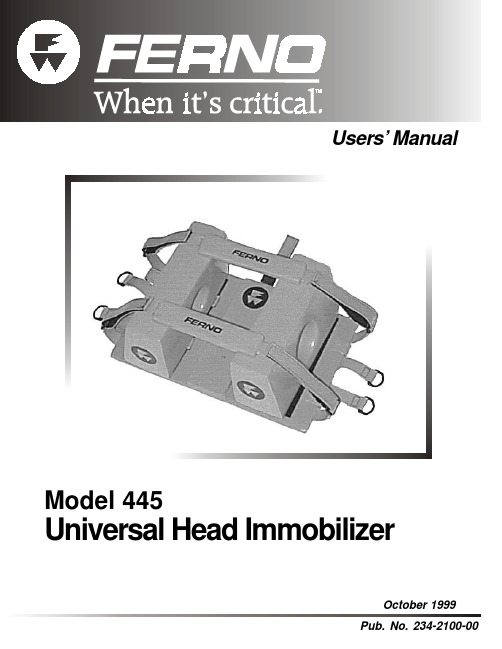
Users’ ManualUsers’ Manual Model 445 Universal Head ImmobilizerDisclaimerThis manual contains general instructions for the use, operationand care of this product. The instructions are not all-inclusive.Safe and proper use of this product is solely at the discretion ofthe user. Safety information is included as a service to the user.All other safety measures taken by the user should be withinand under consideration of applicable regulations. It isrecommended that training on the proper use of this productbe provided before using this product in an actual situation.Retain this manual for future reference. Include it with the productin the event of transfer to new users. Additional free copies areavailable upon request from Customer Service.Proprietary NoticeThe information disclosed in this manual is the property of Ferno-Washington, Inc., Wilmington, Ohio, USA. Ferno-Washington,Inc. reserves all patent rights, proprietary design rights,manufacturing rights, reproduction use rights, and sales userights thereto, and to any article disclosed therein except to theextent those rights are expressly granted to others or where notapplicable to vendor proprietary parts.Ferno-Washington, Inc.70 Weil WayWilmington, OH 45177-9371 U.S.A.T elephone...............800.733.3766Fax..........................937.382.1191Model 445 Universal Head Immobilizer Users’ ManualTABLE OF CONTENTSPageSection 1 - Safety Information (4)Section 2 - Learning About the Head Immobilizer (5)Section 3 - Operator Skills and Training (6)Section 4 - Using the Head Immobilizer (6)Section 5 - Maintaining the Head Immobilizer (10)Section 6 - Repair Parts (11)Section 7 - Limited Warranty (12)Section 8 - Customer Service (12)Training Record (13)Maintenance Record (14)IllustrationsComponents (5)Figure 1 - Retention Straps Threaded Through Cervical Device Slots (7)Figure 2 - Retention Straps Wrapped Under the Backboard (7)Figure 3 - Attaching the Top Retention Strap (7)Figure 4 - Sliding the Base Plate Under the Patient’s Head (8)Figure 5 - Positioning the Support Pads for Use on a Backboard (8)Figure 6 - Using the Angled Side of the Support Padswhen Patient is on a Scoop Stretcher (9)Figure 7 - Fastening the Forehead Strap (9)Figure 8 - Preparing for Storage (9)Users’ Manual Model 445 Universal Head ImmobilizerModel 445 Universal Head Immobilizer Users’ Manual Fastening Strips (2)Top Retention Strap “D” Rings (8)Side Retention Straps (2)Users’ Manual Model 445 Universal Head ImmobilizerModel 445 Universal Head ImmobilizerUsers’ ManualUsers’ Manual Model 445 Universal Head Immobilizer4.4Attaching the Head Immobilizerto a Scoop TM Stretcher1.Separate the head immobilizer components,and unfasten the retention straps.2.Transfer the patient onto the Scoop stretcherusing approved EMS transfer procedures.Read and follow all instructions in the Scoop Stretcher Users’ Manual.3.Slide the head immobilizer base plate underthe patient’s head and onto the Scoop stretcher head panels (Figure 4). This maneuver requires a minimum of two operators. One operator must support the patient’s head and neck while the other operator applies the base plate.4.Wrap the side retention straps under thehead panels of the Scoop stretcher and secure them to the fastening strips on the base plate.5.Loop the top retention strap around theScoop stretcher’s main frame tube; then thread the top retention strap through the plastic buckle and secure it to the fastening strip on the strap itself.4.5Securing the Patientin the Head Immobilizer1.Position the patient on the backboard orScoop stretcher so that his/her head is in the middle of the base plate.2.Secure the patient onto the backboard orScoop stretcher with the restraints provided with the equipment.3.If the patient is on a backboard, place thestraight side of the support pads against each side of the patient’s head (Figure 5).The end of each pad should touch the patient’s shoulders.Note: The support pads may be secured at an angle on the base plate in cases when the patient’s neck is twisted or angulated.Figure 4 - Sliding the Base PlateUnder the Patient’s HeadFigure 5 - Positioning the Support Padsfor Use on a BackboardModel 445 Universal Head ImmobilizerUsers’ Manual4.6Storing the Head ImmobilizerClean and disinfect the head immobilizer before storing (See Maintaining the Head Immobilizer ,page 10).To reassemble the components, loop the retention straps under the base plate and secure them to the fastening strip.Place the support pads on their sides on the base plate.Place the forehead/chin straps on the support pads and secure the ends in the “D” rings (Figure 8).Note: The head immobilizer base plate can also be stored attached to a backboard.4.If the patient is on a Scoop stretcher, placethe angled side of the support pads against the patient’s head (Figure 6). The end of each pad should touch the patient’s shoulders.When possible, align the holes in the support pads with the patient’s ears. This helps the patient hear the operator and allows the operator to check the patient’s ears.5.Center a forehead/chin strap on the patient’sforehead, with the fastening strips facing up.6.Loop each end of the forehead/chin strapthrough a “D” ring. Tighten as needed and secure the ends to the fastening strips on the forehead/chin strap (Figure 7).7.Follow local EMS protocols to determine theuse and placement of the second forehead/chin strap.Figure 6 - Using the Angled Side of the Padswhen Patient is on a Scoop StretcherFigure 8 - Preparing for Storage Figure 7 - Fastening the Forehead StrapUsers’ Manual Model 445 Universal Head ImmobilizerSECTION 7 - LIMITED WARRANTYLimited Warranty SummaryFerno-Washington, Inc. (Ferno), warrants the products we manufacture to be free from defects in material and workmanship for one year except as follows:(A) Soft goods (webbing, vinyl, fabric, foam, etc.) are warranted for 90 days.This limited warranty applies when you use and care for the product properly. If the product is not used and cared for properly, the warranty is void. The warranty period begins the day the product is shipped from Ferno or the day you receive it if you have proof of the delivery date. Shipping charges are not covered by the limited warranty. We are not liable for shipping damages or damages sustained through using the product.Limited Warranty ObligationIf a product or part is proven to be defective, Ferno will repair or replace it. At our option, we will refund the product’s purchase price. The purchaser accepts these terms in lieu of all damages.This is a summary of the limited warranty. The actual terms and conditions of the limited warranty, and the limitations of liability and disclaimers, are available upon request by calling 800.733.3766 or 937.382.1451.SECTION 8 - CUSTOMER SERVICECustomer service and product support areimportant aspects of each Ferno product.For assistance with the Model 445 UniversalHead Immobilizer, contact Ferno CustomerService.Ferno-Washington, Inc.70 Weil WayWilmington, OH 45177-9371 U.S.A.Telephone...........800.733.3766Fax......................937.382.1191TRAINING RECORDDate Name Training MethodMAINTENANCE RECORDDate Maintenance Performed ByNOTES。
3M Dual Lock 双向锁定快捷夹带用户指南说明书

3Dual Lock ™Reclosable Fasteners with Acrylic Foam Tape Summary Most substrates are best prepared by cleaning with a 50:50 mixture of isopropyl alcohol (IPA)and water *prior to applying 3M™Dual Lock™Reclosable Fasteners.Exceptions to this general procedure that may require additional surface preparation include:•Heavy Oils: A degreaser or solvent-based cleaner may be required to remove heavy oil or grease from a surface and should be followed by cleaning with IPA/water.•Abrasion: Abrading a surface, followed by cleaning with IPA/water, can remove heavy dirt or oxidation and can increase surface area to improve adhesion.•Adhesion Promoters: Priming a surface can significantly improve initial and ultimate adhesion to many materials such as plastics and paints.•Porous Surfaces: Most porous and fibered materials such as wood, particleboard, concrete,etc. need to be sealed to provide a unified surface.•Unique Materials: Special surface preparation may be needed for glass and glass-like materials, copper and copper containing metals and plastics or rubber that contain components that migrate (e.g. plasticizers).*Note: These cleaner solutions contain greater than 250 g/l of volatile organic compounds (VOC). Please consult your local Air Quality Regulations to be sure the cleaner is compliant. When using solvents, extinguish all ignition sources,including pilot lights, and follow the manufacturer’s precautions and directions for use. Be sure to follow all government regulations and the manufacturer’s precautions and directions for use when using solvents or other cleaning methods.GeneralProcedure •The Dual Lock reclosable fasteners and substrates should have equilibrated for a minimum of one hour at temperatures of 68°to 80°F (20°to 27°C) before application.•To obtain optimum adhesion, thebonding surfaces must be well unified(see porous surfaces above), clean anddry. Typical surface cleaning solventsare IPA/water mixture (rubbing alcohol)or heptane.*(Steps A and B.)•Application Procedure: Bond strengthis dependent upon the amount ofadhesive-to-surface contact developed.Firm application pressure develops betteradhesive contact and helps improve bondstrength. (Steps C and D.)Application Guide3M™Dual Lock™Reclosable Fasteners with Acrylic Foam TapeGeneral Procedure (continued)•3M™Dual Lock™Reclosable Fastener Application Procedure:°For small pieces: The liner is removed from the Dual Lock reclosable fastener adhesive. Without touching the adhesive, the Dual Lock reclosable fastener is applied to the surface using light finger pressure. The Dual Lock reclosablefastener must then be rolled down with a rubber-covered hand roller, beingcareful not to crush the Dual Lock reclosable fastener stems. It is suggested to roll down the Dual Lock reclosable fastener at least once in each direction witha 4.5 lb. to 10 lb. roller to insure 100% adhesive contact, especially around theperimeter of the part.°For long strips: The liner is removed from the Dual Lock reclosable fastener adhesive. Without touching the adhesive, the Dual Lock reclosable fastener is aligned on the substrate surface. One end of the Dual Lock reclosable fastener strip is pressed down (tabbed) to the substrate while holding the other end of the strip under light tension. The Dual Lock reclosable fastener strip is thenslowly rolled down the entire length of the strip from the tabbed end with arubber covered hand roller, taking care not to trap air bubbles under theadhesive and not to crush the Dual Lock reclosable fastener stems. It issuggested to roll down the reclosable fastener at least once in each direction with a 4.5 lb. to 10 lb. roller to insure 100% adhesive contact, especially around the perimeter of the part.•Evaluate Application Procedure: A Clear Test Panel (Glass, Acrylic, or Polycarbonate) can be used to evaluate and improve application procedure. Using the above procedure, apply the Dual Lock reclosable fastener to a Clear Test Panel. After Dual Lock reclosable fastener has been applied, examine the back side of the panel for adhesive wet out (contact area). It is important to adjust application procedure and roll down to insure almost 100% contact, especially around the perimeter of the parts.•The pressure-sensitive adhesive bonds to the substrate on contact and parts can be handled immediately. Adhesive bond strength increases with time, pressure and temperature. A minimum of twenty four hours dwell time is recommended before applying a load or disengaging assembled parts.°After application, the bondstrength will increase as theadhesive flows onto thesurface. At room temperature,approximately 50% of theultimate strength will beachieved after 20 minutes,90% after 24 hours and 100%after 72 hours. In some cases,bond strength can beincreased and ultimate bondstrength can be achieved more quickly by exposure of the bond to elevatedtemperatures (e.g. 150°F [66°C] for 1 hour).Application Guide3M™Dual Lock™Reclosable Fasteners with Acrylic Foam TapeHeavy Oils On surfaces with a light oily film, or other light contamination, the 50:50 IPA/water solution is usually adequate. Where heavy oils or grease are present, a “degreasing” solvent such as 3M™Prep Solvent 70,3M™Citrus Base Cleaner, mineral spirits, naphtha or similar solvents are suggested to cut the oil. Thisshould always be followed with an IPA/water cleaning to help ensure that any residue or film is removed.*Abrasion Abrading a surface can serve several functions:•Remove heavy levels of dirt or oxide from metals or paints (e.g. galvanized steel).•Create additional surface area that can increase adhesion.•Smooth a surface to obtain more flatness, allowing improved contact area.Abrasion often helps adhesion to paints and plastics. When abrading, it is important for tapes to have afinely abraded surface. Very small scratches in the surface, generated with circular motion rather thanstraight-line motion, are most desirable. A surface with many micro-scratches in it can have up to 40%additional available surface area, translating to higher ultimate strength and greater initial adhesion.Scotch-Brite®Hand Pads (such as 7447 Maroon or Heavy Duty Green) are good for achieving the rightlevel of abrasion. Tools such as a power palm sander will assist on large jobs. Avoid grinding a surfacewith coarse abrasive materials, since they may create too rough of a texture for the adhesive toadequately flow into the surface. Always clean the surface with the IPA/water solution or additionalmethods previously described, and be certain that all loose particles are removed prior to bonding.Adhesion Promoters Priming a surface can significantly improve initial and ultimate adhesion to many materials such as plastics and paints because of their low surface energy or the additives they may contain. A primer creates a new surface for 3M™Dual Lock™Reclosable Fasteners to adhere to and can also create a layer that may impede the migration of additives that may be present in a material. If needed for LSE and difficult to bond to substrates, lightly abrading a surface with Scotch-Brite®Hand Pad prior to applying the adhesion promoter can sometimes improve its bond performance to the substrate. It is important for the user to determine the suitability of the Dual Lock reclosable fastener, the adhesion promoter and the application process. Consult Technical Data Sheet on individual promoters for suggested application procedure.Porous Surfaces Rough, porous or fibered materials such as wood, particleboard, cement, etc., have an open surface and require sealing to provide a unified surface for tape bonding. Common sealing materials would include paint, varnish or other hard surface coatings. Fast drying 3M™Rubber & Vinyl 80 Spray Adhesive can also be used to unify the surface and improve the tape bond.Unique Surfaces Glass, stone, ceramic or other siliceous materials are hydrophilic (water-loving) by nature. Normally, the hydrophilic nature makes pressure sensitive adhesive bond durability susceptible to change under high humidity or exposure to moisture. In basic terms, water vapor can undercut the tape bond and interfere with the normal adhesion forces. Silane coupling agents, added to the IPA/water cleaning solution, can help reduce the “water-loving” tendency of these surfaces and enhance the tape bond in high moisture environments.Copper, brass, and bronze are prone to oxidation even after the Dual Lock reclosable fastener is applied. To prevent a weakening of the bond, a lacquer or varnish should be applied to these surfaces. Be sure to test the tape bond to the sealer on a metal surface to verify good adhesion.Flexible PVC (vinyl) contains plasticizers that can migrate into the tape and affect adhesion. The Dual Lock reclosable fasteners with Multi-Purpose 1 or 2 Acrylic Adhesives are formulated to be resistant to plasticizer migration, or 3M™Adhesive Promoter 2262AT can serve as a barrier to migration. Rubber materials (e.g. EPDM, neoprene) can have low surface energy and may also contain plasticizers and oils. These require the use of an adhesion promoter for stable bond strength. Test for compatibility with flexible PVC and rubber materials by aging bonded samples for a week at 150°F (66°C) and check for softening of the adhesive, discoloration or reduction in bond strength.*Note: These cleaner solutions contain greater than 250 g/l of volatile organic compounds (VOC). Please consult your local Air Quality Regulations to be sure the cleaner is compliant. When using solvents, extinguish all ignition sources, including pilot lights, and follow the manufacturer’s precautions and directions for use. Be sure to follow all government regulations and the manufacturer’s precautions and directions for use when using solvents or other cleaning methods.Application Guide3M™Dual Lock™Reclosable Fasteners with Acrylic Foam TapeSuggested Primers The table below offers suggested primers and alternative methods that commonly require primers, adhesion promoters or other surface treatments for successful use with 3M™DualLock™Reclosable Fasteners. This list is not intended to be fully comprehensive, but maybe useful for many applications.It is very important for the user to determine the suitabilityof the Dual Lock reclosable fasteners, primer and application process and compliance withlocal Air Quality Regulations.P - Primary ChoiceX - Other Possibilities3M™Adhesion Promoter 2262AT is not a preferred OEM recommendation for exterior applications.Solvent-based adhesion promoter use limited in California as required by Air Quality Management Directive.4298UV and K520UV are premixed with UV dye.*Note:These primers contain greater than 250 g/l of volatile organic compounds (VOC). Solvent based adhesion promoter use limited in California as required by Air Quality Management Directive. Please consult your local Air Quality Regulations to be sure these primers are compliant.(a)3M™Adhesion Promoter 2262AT contains 57 g/l VOC less water and less exempt solvent.(b)See supplier information.Application Guide3M ™Dual Lock ™Reclosable Fasteners with Acrylic Foam Tape Sources Hand held J-Roller:Rockler Woodworking and HardwarePhone: (800) 279-4441Specify #Run an Evaluation Because 3M cannot anticipate all of the different possible surfaces and contaminantsthat may exist, it is imperative that the user conduct an evaluation to determine the suitability of 3M™Dual Lock™Reclosable Fasteners, surface preparationsprocedures, and any other processes that may have an influence on the tape or the bonded parts. Likewise, where there are any changes in plastic or paint formulation,or suppliers of these materials, it is advisable to run evaluations to ensure that the change has not influenced the compatibility of the surface with Dual Lock reclosable fasteners.Primer Sourceand Description •3M™Primer 94,3M™Adhesion Promoter 111 and 3M™Silane Glass Treatment AP 115 are available through distributors that carry 3M™DualLock™Reclosable Fasteners.•3M™Adhesion Promoter 2262AT is ready-to-use, pre-diluted (ten partsAcetone/one part 2262) version of 3M™Scotch-Grip™Plastic Adhesive 1099.•3M™Adhesion Promoters are available from Customer Service at (317) 290-1600.•Silane Coupling Agent is also available premixed in a 91:9 IPA/water solution or as a concentrate. A 0.5 wt. % level of silane *adhesion promoter diluted in a 91:9 IPA/water cleaning solution has been found to be sufficient.Suggested Sources for Silane Coupling Agents:Custom-Pak Products, Inc.(262) 251-6180available premixed in IPA/water Lancaster Synthesis, Inc.(603) 889-3306available 100% concentrated *Note: Be sure to read and follow silane and solvent manufacturer’s precautionsand directions for use for proper handling and storage information.Application Guide3M ™Dual Lock ™Reclosable Fasteners with Acrylic Foam Tape 3M warrants for 24months from the date of manufacture that 3M ™Dual Lock ™Reclosable Fastenerswith Acrylic Foam Tape will be free of defects in material and manufacture. 3M MAKES NO OTHER WARRANTIES, EXPRESS OR IMPLIED, INCLUDING BUT NOT LIMITED TO, ANY IMPLIEDWARRANTY OF MERCHANTABILITY OR FITNESS FOR A PARTICULAR PURPOSE. This limited warranty does not cover damage resulting from the use or inability to use 3M ™Dual Lock ™Reclosable Fasteners with Acrylic Foam Tape due to misuse, workmanship in application, or application or storage not in accordance with 3M recommended procedures.Limited Warranty If the 3M ™Dual Lock ™Reclosable Fasteners with Acrylic Foam Tape is proved to be defective within the warranty period stated above. THE EXCLUSIVE REMEDY , A T 3M ’S OPTION, SHALL BE TO REFUND THE PURCHASE PRICE OF OR TO REPAIR OR REPLACE THE DEFECTIVE 3M ™DUALLOCK ™RECLOSABLE FASTENERS WITH ACRYLIC FOAM TAPE. 3M shall not otherwise be liable for loss or damages, whether direct, indirect, special, incidental, or consequential, regardless of the legal theory asserted, including negligence, warranty, or strict liability.Limitation of Remedies and Liability All statements, technical information and recommendations contained in this document are based upontests or experience that 3M believes are reliable. However, many factors beyond 3M ’s control can affect the use and performance of a 3M product in a particular application, including the conditions underwhich the product is used and the time and environmental conditions in which the product is expected to perform. Since these factors are uniquely within the user ’s knowledge and control, it is essential that the user evaluate the 3M product to determine whether it is fit for a particular purpose and suitable for the user ’s method of application.Product Use This Industrial Adhesives and T apes Division product was manufactured under a 3M quality system registered to ISO9001:2000 standards.Scotch-Brite is a registered trademark of 3M Company.3M, Dual Lock and Scotch-Grip are trademarks of 3M Company.Santoprene is a trademark of Monsanto Corporation.Printed in U.S.A.©3M 200870-0709-4029-4(2/08)Recycled Paper 40% pre-consumer10% post-consumer 3Industrial Adhesives and Tapes Division3M Center, Building 21-1W-10, 900 Bush Avenue St. Paul, MN 55144-1000800-362-3550 • 877-369-2923 (fax)/industrial。
Ryobi EX26 电锯用户手册说明书

- 1、下载文档前请自行甄别文档内容的完整性,平台不提供额外的编辑、内容补充、找答案等附加服务。
- 2、"仅部分预览"的文档,不可在线预览部分如存在完整性等问题,可反馈申请退款(可完整预览的文档不适用该条件!)。
- 3、如文档侵犯您的权益,请联系客服反馈,我们会尽快为您处理(人工客服工作时间:9:00-18:30)。
E
17
二、 紧固件基本知识
管螺纹的分类
E
18
二、 紧固件基本知识
3.2 管螺纹的特征代号
E
19
二、 紧固件基本知识
4. 螺纹配合等级 4.1 螺纹配合是旋合螺纹之间松或紧的大小,配合的等级是作用在内外螺纹上偏差 和公差的规定组合。 • 公制螺纹,外螺纹有三种螺纹等级:4h、6h和6g,内螺纹有三种螺纹等级:5H 、6 H、7H。H和h的基本偏差为零。G的基本偏差为正值,e、f和g的基本偏差 为负值。如图所示: 4.1.1 H是内螺纹常用的公差带位置,一般不用作表面镀层,或用极薄的磷化层。G 位置基本偏差用于特殊场合,如较厚的镀层,一般很少用。 4.1.2 g常用来镀6-9um的薄镀层,如产品图纸要求是6h的螺栓,其镀前螺纹采用6g的 公差带。 4.1.3 螺纹配合最好组合成 H/g、H/h或G/h,对于螺栓、螺母等精制紧固件螺纹,标 准推荐采用6H/6g的配合。
E
10
二、 紧固件基本知识
2.3 非螺纹密封的管螺纹(又称圆柱管螺纹)(GB7307与ISO 228/1相同) 螺纹代号G,牙形角55°,基本牙形为圆顶圆底。 精度等级:内螺纹标准级和D级,外螺纹A、B级。
特点:用于管件联接的三角螺纹,α=55° 螺纹面间没有间隙,密封性好,适用于压强在1.6MPa以下的联接
E
2
一、 790-GTP-0005 简介 /Brief
•紧固力矩/ TIGHTENING TORQUE :碳钢,不锈钢,铜制螺钉 •Steel, Stainless steel, brass screws •锁固/ LOCKING:螺纹锁固胶使用方法。 •How to apply locking fluid. •垫片/Washer:垫圈的使用方法。 •How to use washer. •螺钉/Screw:使用范围。 •Using scope. •检查/ INSPECTION
铝件,铜件及钢性复合件连接垫片使用 Washers in screw joints with aluminium, copper and rigid laminate
脆性或易碎性件连接垫片使用 Washers in screw joints with brittle materials
E
4
二、 紧固件基本知识
E
3
一、 790-GTP-0005 简介 /Brief
长圆孔连接垫片使用 Washers for oblong holes
钢件连接垫片使用 Washers in screw joints with steel 铝件,铜件及钢性复合件连接垫片使用 Washers in screw joints with aluminum, copper and rigid laminate
M20×1.5-6H 细牙螺纹标记必须标明螺距1.5
粗牙螺纹螺栓或螺钉:M20×20-6g 20螺栓或螺钉的长度 细牙螺纹螺栓或螺钉:M20×1.5×20-6g 6H、6g表示螺纹精度等级,大写精度等级代号表示内螺纹,小写精度等 级代号表示外螺纹
E
8
二、 紧固件基本知识
2.2 美标统一螺纹(又称60°英制螺纹) 螺纹代号UNC、UNF、UNEF、UN、UNS,牙形角60°,基本牙形为平顶。 精度等级:内螺纹1B~3B,外螺纹1A~3A。
E
6
二、 紧固件基本知识
2. 几种常用的螺纹
2.1 普通螺纹(又称米制或公制螺纹) 螺纹代号M,牙形角60°,基本牙形为平顶,分粗牙、细牙。 精度等级:内螺纹4~8级,外螺纹3~9级。
E
7
二、 紧固件基本知识
粗牙:常用。螺纹的直径 和螺距的比例适中、强度 好; 细牙:自锁性能更好。常 用于承受冲击、振动及变 载荷、或空心、薄壁零件 上或轴向尺寸受限制的场 合及用于微调机构 细牙的缺点:牙小,相同 载荷下磨损快,易脱扣 标记示例: 粗牙螺纹螺母: 细牙螺纹螺母: M20-6H 粗牙普通螺纹标记一般不标明螺距
E
21
二、 紧固件基本知识
5. 螺纹联接零件常用材料和机械性能等级 5.1 目前市场上标准件主要有碳钢、不锈钢、铜三种材料 5.1.1 碳钢 以碳的含量区分为低碳钢,中碳钢和高碳钢以及合金钢。 5.1.1.1 低碳钢: C%≤0.25% 通常称为A3(Q235A)钢。主要用于4.8级螺栓及4级 螺母、小螺丝等无硬度要求的产品。 5.1.1.2 中碳钢0.25%<C%≤0.45% 通常称为35号、45号钢,主要用于8级螺母、8.8 级螺栓及8.8级内六角产品。 5.1.1.3 高碳钢: C%>0.45%。目前市场上基本没使用 5.1.1.4 合金钢:在普碳钢中加入合金元素,增加钢材的一些特殊性能:如35、 40CrMo。 5.1.2 不锈钢 性能等级:45,50,60,70,80 奥氏体(18%Cr、8%Ni)耐热性好,耐腐蚀性好,可焊性好。A1,A2,A4 马氏体( 13%Cr )耐腐蚀性较差,强度高,耐磨性好。C1,C2,C4 铁素体 F1。 5.1.3 铜 常用材料为黄铜、锌铜合金。市场上主要用H62、H65、H68铜做标准件。
E
15
二、 紧固件基本知识
3. 管螺纹综述 3.1 管螺纹的分类
•
按单位制划分,管螺纹分为英寸制管螺纹和米制管螺纹 两大类。其中,英寸制管螺纹按牙型又可分为55°管螺 纹和60°管螺纹两种。55°管螺纹也称惠氏管螺纹,是 使用最早的管螺纹,由英国人发明,在欧洲及英联邦国 家占主导地位。60°管螺纹也称为布氏管螺纹,由美国 人发明,在北美洲及美国领先的行业占主导地位。这两 种管螺纹仍是目前影响较大、应用最广的管螺纹。米制 管螺纹是德国、俄罗斯和我国利用米制普通螺纹的牙型 ,制定了各自的米制锥螺纹国家标准。但这种米制密封 管螺纹目前没有被世界上的多数国家接受。因此,应用 受到限制。只能用在不与外界直接发生关系的局部连接 上。目前还不能随意采用。
标记示例: 11/2 ″左旋内螺纹 11/2 ″A级外螺纹 11/2 ″B级外螺纹 内外螺纹装配 G11/2-LH(右旋不标) G11/2A G11/2B G11/2 /G11/2A
E
12
二、 紧固件基本知识
2.4 用螺纹密封的管螺纹(GB 7306与ISO7/1相同) 螺纹代号R、Rc、Rp,牙形角55°,基本牙形为圆顶圆底,锥度1:16
•紧固件:螺纹连接 •Fastener: Thread joints •特点:构造简单,拆装方便,工作可靠,标准件,应用广 •Character: Simple structure, dismounting easily, working credibly
E
5
二、 紧固件基本知识
1. • • • • • • • • 螺纹的分类 / Type of thread 按牙形:三角形螺纹、矩形螺纹、梯形螺纹、锯齿形螺纹、管螺纹 Shape of thread: triangular thread, rectangular thread, trapezoidal thread, saw-tooth thread, gas thread 按母体形状:圆柱螺纹、圆锥螺纹 Shape of stick:cylindrical thread, taper thread 按线数:单头螺纹和多头螺纹 按旋入方向:左旋螺纹和右旋螺纹 按特点:米制普通螺纹、用螺纹密封的管螺纹、非螺纹密封的管螺纹 、60°圆锥管螺纹、米制锥螺纹 按用途:联接螺纹和传动螺纹
E
11
二、 紧固件基本知识
非螺纹密封的管螺纹(又称圆柱管螺纹) 行内人通常用分来称呼螺纹尺寸,一吋等于8分,1/4吋就是2分,如此类推 公制螺纹用螺距来表示,美英制螺纹用每英寸内的螺纹牙数来表示 公制螺纹用公制单位,美英制螺纹用英制单位 外螺纹中径公差有A、B之分。A级的精度比B 级高。内螺纹由于无公差等 级之分,所以,也就无公差等级标记。
ELeabharlann 16二、 紧固件基本知识
3. 管螺纹综述 3.1 管螺纹的分类
•
管螺纹按密封性又可分为密封管螺纹和非密封管螺纹。 密封管螺纹靠螺纹自身密封。一般密封管螺纹也可填加 密封介质,以进一步提高螺纹密封性。但干密封管螺纹 完全凭自身的密封性实现密封。密封管螺纹的螺纹副有 “锥/锥”配合和“柱/锥”配合两种。非密封管螺纹不具备 密封功能,只用于管路连接。其螺纹副只有“柱/柱”配 合一种。
特点:螺纹均布在锥度为1:16的管上,α=55°或60 ° 螺纹面间没有间隙,不用填料,靠牙变形,密封性好,适用于高温、高压的联接
E
13
二、 紧固件基本知识
用螺纹密封的管螺纹有圆柱内螺纹和圆锥外螺纹、圆锥内螺纹和圆锥外螺纹 两种连接形式。压力在5×10⁵Pa以下时,用前一种连接已足够紧密,后一种 连接通常只在高温及高压下采用。 2.4.1 用螺纹密封的管螺纹内螺纹有圆锥、圆柱两种形式。外螺纹只有圆锥 一种形式。牙型如下:锥度1:16,牙形角55°,旧螺纹标准示例:ZG3/8; 2.4.2 标记示例: 圆锥内螺纹 圆柱内螺纹 圆锥外螺纹 当螺纹为左旋螺纹时 Rc Rp R Rc 3/8 3/8 3/8 3/8-LH(LH表示左旋螺纹)
E
9
二、 紧固件基本知识
q UNC 粗牙系列的统一螺纹 q UNF 细牙系列的统一螺纹 q UNEF 超细牙系列的统一螺纹 q UN 恒定螺距系列的统一螺纹 美国标准 ANSIB1.1 (牙底是平的或随意 倒圆的)的内、外螺纹 q UNS 特殊系列的统一螺纹 标记示例: 粗牙螺纹: 5/16-18 UNC-2A 数18,精度等级为2的外螺纹 细牙螺纹: 5/16-24 UNF-2B 等级为2的内螺纹 粗牙普通螺纹,大径5/16"(7.9375mm),每英寸牙 细牙普通螺纹,大径5/16",每英寸牙数24,精度 标准牙型
E
14
二、 紧固件基本知识
2.5 60°圆锥管螺纹 螺纹代号NPT、NPTF,牙形角60°,基本牙形为平顶,锥度1:16 NPT 一般用途的锥管螺纹 美国标准 ANSIB1.20.1 牙型角为60°的 英制管螺纹 NPTF 干密封标准型锥管螺纹 美国标准 ANSIB1.20.3 Ⅰ型