JumpMind Metl 用户指南
Justinmind教程06
固定位置效果
教程小楼一夜听春语
在我们实际工作中,经常会遇到屏幕中的某一部分需要固定位置(问这个问题的人也比较多),不能随着页面的滑动改变位置。
比如:导航菜单。
那么这个效果如何在Justinmind中实现呢?
其实很简单,我们只需要把滑动的部分放入动态面板中,就可以达到目的。
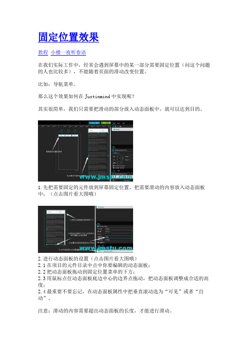
1.先把需要固定的元件放到屏幕固定位置,把需要滑动的内容放入动态面板中;(点击图片看大图哦)
2.进行动态面板的设置(点击图片看大图哦)
2.1在项目的元件目录中点中你要编辑的动态面板;
2.2把动态面板拖动到固定位置菜单的下方;
2.3用鼠标点住动态面板底边中心的边界点拖动,把动态面板调整成合适的高度;
2.4最重要不要忘记,在动态面板属性中把垂直滚动选为“可见”或者“自动”。
注意:滑动的内容需要超出动态面板的长度,才能进行滑动。
这时候进行预览,就会实现想要的效果了。
Presidium Diamond Mate 用户手册 (Chinese Version)说明书

目录(Chinese Version)I. 关于本手册 pg 19 II. 关于Presidium Diamond Mate pg 20 III. 重要说明 pg 221. 开始使用 Presidium Diamond Mate pg 232. 在 Presidium Diamond Mate上执行检测 pg 27 3. 在 Presidium Diamond Mate上读取检测结果 pg 29 4. 维护 Presidium Diamond Mate pg 30I. 关于本手册感谢您购买 Presidium Diamond Mate(简称“PDMT”或“检测仪”)。
本手册旨在帮助您设置检测仪,并且将介绍关于如何正确地使用检测仪及按照要求对其进行护理的所有知识。
请仔细阅读这些说明,将其放在方便之处以便将来参考。
本手册可同时用于 PDMT-A 与 PDMT-C。
II. 关于 Presidium Diamond MatePresidium Diamond Mate 是一种袖珍仪器,可根据导特性即刻鉴别钻石的真伪。
它是以澳大利亚新南威尔士大学 Julian Goldsmid 教授的发明为基础的。
钻石具有优异的导热性,与其他任何天然或人造仿品都不同,因此并不容易复制。
和市面上所有热敏检测仪一样,Presidium Diamond Mate 不能分辨天然钻石和莫桑石。
Presidium Diamond Mate 经过周密广泛的实验室测试,在正确使用的条件下可为受测宝石给出明确而可靠的读数。
但是建议您执行可资旁证的其他检测。
Presidium Diamond Mate 的特点如下:• 可伸缩的热电探针头,确保探针头和宝石之间的压力保持恒定• 业内最细的探针头 (0.6mm),可用于检测小至0.02ct 的宝石• 金属报警蜂鸣器,确保在检测时探针头与宝石保持接触• 可连续检测,无须等待• 清晰易读的 LED 显示屏• 低电量指示灯• 电池消耗量很低包装物品:• Presidium Diamond Mate 检测仪• 保护性便携袋• 3 节 AAA 充电电池*• AC 适配器/充电器(120/230 伏)*• 快速指南• QR码卡* 仅限于 PDMT-C1可伸缩的探针头2电源指示 LED3显示面板4适配器插口5电池匣6锯齿状金属部件7打开/关闭 (ON/OFF) 开关8探针保护帽III. 重要说明• 保持检测仪干燥。
MJ-SERIES PulSE METER 产品说明书

MJT (cold water) and MJHT (hot water) meters do not have a sensor, and they totalize only.
Internals Engineered thermoplastic
Magnet Alnico
Accuracy
+/- 1.5% of reading
Pulse Output Sensor Max Current Max Voltage
MJE/MJHE Hall-ef fect
20 mA 24 Vdc
Inlet Strainer. Clean the strainer yearly, or as required, depending on water condition. Pull out the strainer or backflush the meter to loosen trapped particulates.
SPECIFICATIONS*
MJ-Series meters use the internationally-accepted multi-jet principle. A gear train drives the register totalizer dials. For pulse output, one of the pointers is replaced by a magnet arm, which is detected by an encapsulated sensor attached to the outside of the lens.
魅玛轻型迷你PTZ控制器RM-LP5用户手册说明书

Mini PTZ Controller RM-LP5User ManualParameters & Specs Communication & Control Interface Camera Control or Operation Control Signal FormatPower Supply and ConsumptionPhysical & Others Description of Button & Knob FunctionInterface Function and Connection Diagram Upgrade Interface RS422/RS485 Interface RS232 Interface LAN Interface12V DC Power InterfaceSystem Menu Operation Instructions System Menu Function Explanation Keyboard System Menu System Setting Comm Setting Ethernet SettingPassword SettingSystem Menu Guide Products DimensionsContent2 2 2 2223 7 7788910 10 10 10 11 11 12 12 13④⑤⑪⑮①This Rotation Knob which was to adjustment the Camera Exposure Parameter or Red Gain Value, Turn Right Rotation was to changed the valued Increased, Turn Left Rotation was changed the Valued Decreased.②This Rotation Knob which was to adjustment the Camera Exposure Parameter or Blue Gain Value, Turn Right Rotation was to changed the valued Increased, Turn Left Rotation was changed the Valued Decreased.③This Rotation Knob which was to adjustment the Camera Exposure Parameter, Turn Right Rotation was to changed the valued Increased, Turn Left Rotation was changed the Valued Decreased.④LED Display, Real-time display of items and parameter values of adjusted by " knob ①".⑤LED Display, Real-time display of items and parameter values of adjusted by " knob ②".⑥LED Display, Real-time display of items and parameter values of adjusted by " knob ③".⑦Zoom Bridge KeyIt is used to control the camera to Zoom In/Out, for example, press the TELE end of the bridge key, the camera will Zoom in the TELE direction object, When you Press with more Large Pressure, then the Zoom Speed changed more Faster.⑧ Focus Function ZoonWhen the Backlight of [AUTO]Button is Light up, it means that the current focusing mode is the automatic; When the Backlight of [AUTO] Button is Light Off, it means that Current Focus Mode is changed to Manual. User can Press this button to switch the mode.[OPT key] is used to trigger the single focus of the camera.At the same time, the camera enters the one-shot auto focus mode.⑨PTZ Speed Adjustment KnobThis knob is used to adjust the speed of Camera Pan, Tlit and Zoom, with a total of 7 gears.The Current Gear will be display at Led Display. The Gear Value is more small then the pan/tilt rotation speed or the zoom speed of the camera controlled by the keyboard will be more Slowly.⑩ 2-Aixs JoystickThe joystick supports control camera to Up/Down, Left and Right movement. When the camera or keyboard menu is opened, the joystick is used to control the menu cursor Up/Down,Left/Right movement and modify parameters.⑪ Channel Button Zone[ CAM1 ] to [ CAM5 ] are shortcut keys for camera channels, which can be Freely switched and selected according to your need. When you select any camera channel, the backlight of the corresponding camera channel will be light up in green, and all the parameters and settings of the keyboard will be changed to the current Channel.Note: The communication parameters (address ID, protocol, baud rate, IP address, port number, etc.) of each channel can be set individually.Support mixed use of multiple protocols through different channel.⑫ Presets Function Zone●[ Number Keys ]SETING PRESETS :Long Press and hold the number key for 2 seconds (such as [Number key 1], when the screen displays "Set Preset 1” means that preset 1 has been saved) CALL PRESETS :Short press the preset number to be call Presets, (for example, [Number key 1],when you press the [Number key 1]the screen displays "Show Preset 1", it means that preset 1 has been call).●[ RESET Key ]TO BE CLEAR THE PRESET SETTINGPress[RESET key]+[Number key]to clear the preset position setting. After pressing the [RESET key], the green backlight starts to flash, Then press the preset number that needs to be cleared, (for example,[RESET]+ [Number key 1], at this time, the green Backlight of button of the [RESET key]stops flashing, and at the same time, “Reset Preset 1” is displayed on the screen, which means that preset 1 has been cleared.⑬ FOCUS KnobThis Knobs is using to adjustment camera’s focal length, Rotation right direction is adjustment focus length near, Rotation Left direction is adjustment focus length Far; (When User using this function, the keyboard’s Focus mode will be changed to Manual, It wasn’t available on AUTO Mode).⑭ Function Key Zone●[Menu Key]This key is to Turn ON/OFF Camera Menu, Long Press with 3secs will turn on Keyboard system Menu.●[AE MODE Key]This key is used to change the automatic exposure mode of the camera. Each time is pressed, the camera changes to different exposure mode. Under in difference of exposure mode, the corresponding functions of Knob 1, Knob 2 and Knob 3 are different. It is shown in real time on the display at the right of the knob.● [ WB MODE Key ]This Key is used to changed the White Balance of the camera. Each Time is pressed, the camera will be changed to different WB Mode.Under in difference ofWB mode, the corresponding functions of Knob 1, Knob 2 are different.The specific functions of the knobs are shown in Table 2:●[ Fn Keys ]This key is reserved for adding custom functions.The factory default state is: short press this key to send the command to enter theSub-menu of the camera, long press this key for 3 seconds to back Home Position of Camera.⑮ LED DISPLAYIt is used to display the current status information & Setting information of the keyboard in real time (including IP address, Port number, serial port address, communication protocol, Baud Rate and other information) and keyboard menu,the brightness of the display can be set through the keyboard menu.White Balance ModeKnob 1Knob 2AutoNOT USED NOT USED Manual Red GainBlue GainTable 2The interface is for upgrade of Hardware of keyboard by Laptop. Using Micro USB Cable direct connection with PC, And Upgrade by our upgrade tools software.This Interface is using to Connection with Camera by RS422 or RS485,detail connection diagram as follows pictures:③ RS232 InterfaceThis Interface is using to connection with Camera through RS232, detailThe LAN Interface is using for connection with Network switch or others.Network PTZ Camera, detail connection diagram as follows:●This interface is the Power supply interface, you can direct connection it with Power adapter; please don’t using non-original Power adapter.⑤ DC Power Supply Interface● Connect with multiple cameras by LAN interface detail connection diagram as follows:(When connecting multiple cameras, you need to set the IP of each camera separately1.Long Press [ MENU ] with 3secs will turn on Keyboard system Menu;2.The joystick swings up and down: control the system menu cursor to move up and down / change the parameters of the current menu item;3.The Joystick swings Right: enter the current menu item / save and exit the current menu item;4.The Joystick swings Left: Exist current Menu item/ No Saved and Exit current Menu item;5.Press [ MENU ]to exist System Menu;6.Press the number keys[0]~[9]: input numerical value (only valid for menu items that need to input numerical value). example IP Address or Port number setting.7.When the current value is number input, the green backlight of [CAM1]~[CAM5] is Light on, and at this time [CAM1]~[CAM5] Corresponds to the numbers 6~0 on the silk screen above the buttons.SYSTEM MENU 1.Long Press [ MENU ] with 3 secs will turn on Keyboard system Menu.2.The joystick swings up and down to control the menu cursor to move up and down SYSTEM SETTING The joystick swings up and down the Cursor to [ System Setting ], then Movement right to enter System Setting menu.● [ Language ]The Joystick swings up/down to [Language], then Movement right to enter setting. The Joystick swing up/down can changed the current Parameters setting, Swing the joystick to the right to save the current parameters and exit the language settingstate. The following menus operate setting is same.Optional Language: Chinese, English; other languages can be customized and developed according to customer needs.● [ LED Display Brigtness ]Change the brightness of the LED display: Low, Normal, High.● [ Automatically Standby ]Set the keyboard to automatically enter standby mode without any operation within a limited time.Select-able: Off, 1 minute, 2 minutes, 5 minutes, 10 minutes, 20 minutes, 30 minutes, 60 minutes.● [ Itself IP ]To setting Keyboard itself IP Address / Port Number, default IP is 192.168.1.88, default Port 52381.System Menu Operation & Explanation 1. System Setting 2. COMM Setting 3. Ethernet Setting 4. Password Setting1. Language : English2. LED Display Brigtness: Normal3. Automatically Standby: Off4. Itself IP: 192.168.001.0885. Itself Port: 523816. Factory default Setting7. About Keyboard●[ Factory default Setting ]To change the Keyboard restore to Factory default setting.● [ About Keyboard ]To review the relevant information of the keyboard, including: keyboard model, Firmware version, factory S/N and other information.●[ Address ]To set the serial communication address of the corresponding channel.If the current communication protocol is VISCA, the communication address can be selected from 1~7. If the current communication protocol is PELCO-D/P,The communication address can be selected from 1~255.●[ Baud Rate ]To set the serial communication Baud Rate of the corresponding channel.Available in: 2400, 4800, 9600, 19200, 38400bps.●[ Protocol ]To set the Serial communication Protocol of the corresponding channel ( Including Serial Communication Protocol and Internet Communication Protocol).Available in: VISCA, PELCO P/D, UDP .ETHERNET SETTINGTo move the cursor to [ Ethernet Setting ], then Movement right to enter Ethernet Setting:●[ Channel ]The available channels CAM1~5 correspond to the buttons [CAM1]~[CAM5].●[ Cam IP ]To set the Cam IP of the corresponding channel, which can be directly input through the number keys. When the number of input digits reaches 3, the cursor will automatically Jump to the next entry.●[ Port ]To set the UDP Port of the corresponding channel, it depend for the UDP Port 1. Channel: CAM1 2. Cam IP: 192.168.1.1623. Port: 52381PASSWORD SETTINGTo move the cursor to [ Password Setting ], then Movement right to enter Password :●[ Using Password ]How to Using the Password Function:To changed the Password setting is Enable;When the password function is Enable, a password is required to enter the menu.The default password is: 8888●[ Modify Password ]The user can change the password by himself. If the password is not changed, the password is the default password.Warning: Please use this function with caution. If the product cannot be used normally due to the password set by the customer, the manufacturer does not assume any responsibility.1. Using Password: Enabled2. Modify PasswordSYSTEM MENU GUIDE nguage: Chinese, EnglishProducts Dimensions The size for Mini Pro PTZ Controller is as below:(Unit of length: mm)。
Jump IDS V3.0JSH用户手册

西安交大捷普网络科技有限公司
3
http:.//
捷普 IDS JSH 用户手册
3.3.4. 路由相关配置.......................................................................................... 22 3.4. 检查配置(show running)................................................................................. 23 3.5. 测试网络连通性.......................................................................................................23 3.6. 添加远程配置主机访问.......................................................................................... 24 3.6.1. 添加信任主机命令.................................................................................. 24 3.6.2. 删除信任主机(no login)命令.......................................................... 24 3.7. 配置保存及重启.......................................................................................................25 4. 配置实例................................................................................................................................... 25 步骤一 配置 IDS 接口 IP 地址........................................................................................... 26 步骤二 配置网络路由.............................................................................................................26 步骤三 检查网络连通性.........................................................................................................26 步骤四 配置内部网络规则组................................................................................................ 26 步骤五 配置远程信任主机.....................................................................................................26 第二部分 附录............................................................................................................................... 27 附录一、名词解释...................................................................................................................27 附录二、TCP 和 UDP 端口................................................................................................... 29 附录三、IP 地址划分............................................................................................................. 34
Mindjet MindManager 15用户使用手册

MindManager 15用户使用手册Windows版本文件编号 1.0MindManager 15用户使用手册MindManager介绍 (1)MindManager 15新特性 (2)一、简介 (5)1.1 思维导图是什么? (6)1.2 Mindjet MindManager是什么? (6)1.3 特点 (6)1.4 四要素 (6)二、安装 (6)三、程序启动和退出 (10)四、界面介绍 (10)五、新建、打开、关闭导图 (10)5.1 新建导图 (11)5.2 打开现有导图 (12)5.3 保存导图 (12)5.4 导出导图 (12)5.5 关闭导图 (12)六、创建导图 (13)6.1 创建新图标 (13)6.1.1 中心主题 (13)6.1.2 重要主题 (13)6.1.3 插入子主题 (14)6.1.4 编辑主题 (14)6.1.5 插入同层级主题 (14)6.1.6 移动主题 (15)6.1.7 删除主题 (15)6.1.8 收集信息 (15)6.2 标记导图 (16)6.2.1 导图标记 (16)6.2.2 任务信息 (16)6.2.3 更多任务信息 (17)6.2.4 追踪进度 (17)6.2.5 连续追踪进度 (18)6.2.6 跟踪决策 (19)6.2.7 编号 (19)6.2.8 创建关联 (20)6.2.9 更新导图标记 (21)6.2.10 超链接 (22)6.2.11 备注 (23)6.2.12 边框 (23)6.2.13 电子表格 (24)6.3 导图样式 (25)七、卸载 (27)八、常用快捷键 (28)九、常见问题 (33)MindManager介绍欢迎使用Mindjet MindManager随时随地进行头脑风暴、组织管理项目,使用可视化框架让您和您的团队实时追踪项目重心、任务、时间状态。
头脑风暴、组织与创造捕捉灵感,管理会议,制定战略性规划,组织一切,MindManager可以为您提供所有您需要的工具,轻松实现。
WalkCheck操作手册

4.3 验收辅助检查 ........................................................................................................................ - 23 -
4.4 数据交互 ................................................................................................................................ - 32 -
4.1.2 打开工程 ....................................................................................................................... - 10 4.1.3 保存工程 ........................................................................................................................- 11 4.2 数据质量检查 ........................................................................................................................ - 11 -
4.5 系统维护设置 ......................................................................................................................... - 38 4.5.1 检查项设置 ..................................................................................................................... - 39 4.5.1.1 增加检查项 ........................................................................................................................... - 39 4.5.1.2 编辑检查项 ........................................................................................................................... - 41 -
DreamMapper 手机应用用户指南说明书

DreamMapperMobile App User GuideApril 26, 2017Table of ContentsSleep Screen (1)How to navigate (2)Changing Data Categories (5)See Additional Details for the Day and Category (6)View a Report (6)Other Menu Choices (7)Feed Screen (7)Learn Screen (7)Apnea tab (7)Equipment tab (7)Troubleshooting tab (7)Goals Screen (7)Coaching Screen (8)Reminders Screen (8)Settings Screen (8)Account (8)Equipment (8)Contact Preferences (8)Help Screen (9)FAQ tab (9)Support tab (9)About tab (9)Welcome!Welcome to DreamMapper1. Here are a few tips to familiarize you with this exciting app.Sleep ScreenWhen you first log on to DreamMapper the “Sleep” screen is displayed and it defaults to the current date. Data is presented in one of three categories: AHI, Usage, and Mask Fit. Usage is the default category. The graph below shows the values for the selected category for a 7-day period including the displayed day. The graph highlights the currently-selected day on the graph in dark blue.1 DreamMapper is the next generation of the SleepMapper app from PhilipsHow to navigateChanging the Date: Tap the chevronsTo go backward or forward in time, tap the chevrons (“<”, “>”) located beside the date. As you change the date, the highlighted bar in the graph and the details at the bottom of the screen reflects the selected date.Changing the Date: Interacting with the graphThe graph responds to your touch, so that you can easily see your data for a different day or even a different week.When a specific day of the graph is tapped, the focus of the currently selected Category will change to the tapped day.Swipe left-to-right on the graph to see the preceding week, or right-to-left to see the following week. The displayed date range confirms the new time period that’s being presented by the graph.Changing Data CategoriesTo change the category and graph: tap the desired categoryThe selected Category will always be in bold, and the default is Usage. To view your AHI or Mask Fit information for a different category tap on the label or value for the category. The pointer at the top of the graph section confirms your selection.See Additional Details for the Day and CategoryThe bottom portion of the Sleep screen shows additional details pertaining to the Category you currently have selected in context of that day.View a ReportTo view a summary report showing Usage, AHI, and Mask Fit.To view the report, click on the more options icon: . Tap on the Generate Report option. Select an End Date and a Day Span for the report then tap the Generate Report button. The report displays on-screen. You can scroll the report vertically, and you can tap on the PDF icon to create a PDF file.Other Menu ChoicesTo navigate to the other menu items tap the menu iconTo see the Menu in the mobile apps tap the icon located in the top-left corner of the screen. When tapped, a menu appears revealing other areas of the application: Feed, Learn, Goals, Coaching, Reminders, Settings, and Help.Feed ScreenThe Feed section displays notifications that have been sent to your account: Reminders, Alerts, and Recommendations. All are ordered by date.Learn ScreenThe Learn section contains links to other helpful information related to Sleep apnea, Equipment Usage, and Troubleshooting.Apnea tabThis page contains links to several videos addressing the causes and treatment of sleep apnea. Equipment tabThis page contains links to videos and online guides related to the use of therapy equipment and DreamMapper.Troubleshooting tabThis page contains links to videos on the subjects of Mask Issues, Device Pressure Issues, Equipment Issues, and Side Effects.Goals ScreenThe Goals screen displays several categories of monthly and personal goals:∙Days with 4+ hours of use in a month∙Consecutive days with use∙Consecutive days with 4+ hours of use∙Consecutive days with >75% Mask FitTap on the “>” symbol to the right of each category to view its definition and to set your personal goals.Coaching ScreenThis section contains links to mini-questionnaires and videos pertaining to Motivation, Heart Risk, and your Feelings about sleep apnea and sleep therapy.Tap on the “>” symbol to the right of a topic to view its mini-questionnaire or video. Reminders ScreenThe Reminders screen is where you set the time intervals at which you will be reminded to clean your mask, humidifier, tubing, and device filters. You can also schedule follow-up reminders. The reminders you schedule here will appear on the Feed screen.To “turn on” a reminder, tap and slide its button. The button changes to this:Next, select a time interval for the reminder from its drop-down list:For the Follow-up Reminder, select or enter a date in the space provided.Settings ScreenThe Settings screen contains information related to your Account, Equipment, and Contact Preferences. AccountFrom here you can change your Username and Password, or any of the account information by tapping on them. You can also log out of DreamMapper.EquipmentThe options in this section allow you to identify your mask and therapy device. You can assign up to two therapy devices. To assign a device, tap on the “>” symbol adjacent to Therapy Device. In the Primary and optional Secondary sections, tap on the “>” symbols adjacent to the Serial Number, Model, and choose to turn on or off Using Bluetooth (device dependent). Enter the serial number as shown on the device. When finished, tap Save. The device Model name appears on the screen. You can then tap and slide the button if you want to connect your phone to the device Using Bluetooth.Contact PreferencesUse the options in this section to specify how DreamMapper should contact you with important information about your therapy data. By default, E-mail is turned on and Text Messages is turned off. Note: Texting is available only for select wireless carriers in the USA.Help ScreenThe Help section contains general information about DreamMapper, terminology definitions regarding sleep apnea and sleep therapy, and Philips contact information.FAQ tabSome of this information may be new or unfamiliar to you. In the FAQ section you will find definitions for all the fields displayed within DreamMapper.Support tabIf you still have difficulty using DreamMapper, use the contact information displayed here for help. We want you to love DreamMapper as much as we do.About tabThis section provides DreamMapper’s Intended Use, applicable Cautions, Warnings, Password Policy, and Philips contact information.9Product SupportPhone: 1 (855) 699-6276 or 1 (724) 387-5036 E-mail: *******************************Australian sponsor details:Philips Electronics Australia Ltd. 65 Epping Road, North Ryde, NSW 2113 Australia1130610 R03 RPM 4/26/2017 English。
DEMO9S12PFAME 快速入门指南 Rev. 1.0说明书

DEMO9S12PFAMEQuick Start GuideRev. 1.00. IntroductionThis quick start guide will walk you through setting up your demo board, connecting it to the PC, and launching the provided example. For more information, please read the demo board’s user’s manual.1. Run the Factory Programmed Example (Standalone Mode)1. Ensure that the light sensor “ENA” jumper is inserted.2. Ensure that all of the “LED ENA” jumpers are inserted.3. Ensure that the two push-button “ENA” jumpers are inserted.4. Ensure that the “RS-232/LIN SEL” jumper selects the “RS-232” position.5. Ensure that the “POWER SEL” jumper selects the “UNREG” position.6. Power on the Demonstration Board through the 12 V DC plug-in power supply.7. The green “POWER” LED on the board should turn on.8. Press the “PP0” push-button. Rotate the potentiometer. Its value will be shown on the LEDs.9. Press the "PP1" push-button. The output of the light sensor will be displayed on the LEDs.10. The value of the potentiometer or the light sensor is also sent to the RS-232 port(baud rate = 9600, data bits = 8, parity = N, stop bits = 1).2. Host ModeThe same example above can be run from the host PC. To do this, the CodeWarrior Development Tools and the SofTec Microsystems Additional Components must be installed first.Install CodeWarrior Development StudioTo install the CodeWarrior Development Studio Special Edition, insert the CodeWarrior CD-ROM into your computer’s CD-ROM drive. A startup window will automatically appear. Follow the on-screen instructions.Install SofTec Microsystems Additional ComponentsThe SofTec Microsystems “System Software” CD-ROM contains other required components to your hard drive. These components include:SofTec Microsystems DLL for DEMO9S12PFAME support;Examples;Demonstration Board’s user’s manual;Demonstration Board’s schematic;Additional documentation.To install the required components, do the following:1. Insert the SofTec Microsystems “System Software” CD-ROM into your computer’s CD-ROM drive. A startupwindow will automatically appear.2. Choose “Install Instrument Software” from the main menu.3. Click on the “Copy SofTec Microsystems DLL to \CodeWarrior for HCS12 V4.7\Prog\gdi” option. An Explorerwindow will open. Copy the “SofTec_BDM12.dll” file to your PC in the “\CodeWarrior for HCS12V4.7\Prog\gdi” folder, relative to the CodeWarrior installation path.4. Click on the “Copy examples for CodeWarrior for HCS12 V.4.7” option. An Explorer window will open. Copythe “DEMO9S12PFAME” folder to your PC, in a location of your choice. These are the examples specific for the demonstration board, and will be used later in the step-by-step tutorial.Note: to install the Additional Components on Windows 2000 or Windows XP, you must log in asAdministrator.First Connection with the PCNote: before to connect the board to the PC, it is important that you install the required system software asdescribed in the previous section.The Evaluation Board connects to a host PC through a USB port. Connection steps are listed below in therecommended flow order:1.Install all the required system software as described in the previous section. 2.Make sure the “POWER SEL” jumper is in the “USB” position. 3.Insert one end of the USB cable into a free USB port. 4.Insert the other end of the USB cable into the USB connector on the Demonstration Board. 5. The first time the Demonstration Board is connected to the PC, Windows recognizes the instrument and starts the“Found New Hardware Wizard” procedure, asking you to specify the driver to use for the instrument. Follow the wizard steps, choosing to install the software automatically when requested.The Evaluation Board’s USB driver is now installed on your system.Step-By-Step Tutorial1. Make sure that the “POWER SEL” jumper selects the “USB” position.2. Ensure that the Demonstration Board is connected to the PC (via the USB cable) and that the board is powered.3. Start CodeWarrior by selecting it in the Windows Start menu.4.From the CodeWarrior main menu, choose “File > Open” and choose the“DEMO9S12PFAME\C\Demo\Demo.mcp” file. This is the board example you copied from the SofTecMicrosystems “System Software” CD-ROM.5. Click “Open”. The Project window will open.6. The C code of this example is contained in the “main.c” file. Double click on it to open it.7. From the main menu, choose “Project > Debug”. This will compile the source code, generate an executable fileand download it to the demo board.8. A new debugger environment will open. From the main menu, choose “Run > Start/Continue”. The programwill be executed in real-time.9. From the main menu, choose “Run > Halt”. The program execution will stop. The next instruction to beexecuted is highlighted in the Source window.10. From the main menu, choose “Run > Single Step”. The instruction highlighted in the Source window will beexecuted, and the program execution will be stopped immediately after.11. From the main menu, choose “Run > Start/Continue”. The application will restart from where it was previouslystopped.TrademarksSMH Technologies is the licensee of the SofTec Microsystems trademark.Freescale™ and the Freescale logo are trademarks of Freescale Semiconductor, Inc.Copyright © 2008 SMH Technologies DC10008Microsoft and Windows are trademarks or registered trademarks of Microsoft Corporation.PC is a registered trademark of International Business Machines Corporation.Other products and company names listed are trademarks or trade names of their respective companies.。
小凡模拟器教程

现在新手学cisco的,基本都在用Dynamips和PT ,但是很多新手不会使用Dynamips,或许你看了这篇文章之后,至少会对Dynamips有点认识,应该基本都会用了。
Now,Follow Me 。
看图说话:按照图中用数字标出的序号来解释该区域:区域1:这里是选择路由器和交换机的个数的,这个地球人应该都知道吧。
区域2:这里可以选择一些不需要Cisco IOS的模拟设备。
如:FrameRelay交换机ATM交换机。
区域3:这里是选择设备类型的,以上都是Dynamips目前所支持的设备类型。
区域4:这里是选择设备类型、IOS存放路径、idle-pc值、NPE类型、虚拟内存(表示虚拟设备的RAM所占的内存大小,因为dynamips在模拟时候需要将主机的物理内存模拟成模拟设备的RAM)、寄存器。
区域5:这里是配置分布式的dynamips的设置区域区域6:这里是设置可以和主机(就是你的物理机)通信的。
区域7:可以直接读取真实设备里的NVRAM里的配置文件(.ini格式)区域8:输入目录是指生成的bat文件保存路径,自己建立哦。
下面根据拓扑来介绍:根据这个拓扑,需要模拟出3个路由器和1个交换机。
下面我们用DynamipsGUI 来配置脚本文件。
(Ps:DynamipsGUI和Dynamipsee都是可视化的写Dynamips的脚本程序。
不是模拟器!!真正的模拟器是Dynamips 。
)下面模拟上面的拓扑全过程:1.打开DynamipsGUI。
然后在[区域1]那里选择3个路由器和1个交换机。
并且选择[桥接到PC](桥接到PC的作用就是用物理机telnet到模拟出来的设备,然后就可以对设备进行配置),在这里路由器我用的IOS是7200的,交换机用的是3640的(IOS网上很多,可以自己去找。
),所以总的来说我只需要2个IOS文件既可,所以在设备类型这里我只需要勾选7200和3640这2个复选框既可。
如图:2.接着就是在[区域2]那里选择设备的类型和IOS文件路径,选择好之后,需要计算idle值,点击[计算idle]按钮(idle-pc只是为了解决在开启模拟设备的时候不至于你的物理机CPU占有率达到100%,所以这个值很重要)3.点击[计算idle]按钮之后,会弹出一个提示,选择确定即可:4.接着就会弹出一个窗口。
Multimeter用户指南说明书

Press SELECT to switch between resistance,AC/DC voltage, continuity buzzer and diode measurement modes. Press and hold to exit “sleep” mode. 2HOLDPress HOLD to enter and exit hold mode (except under auto scan mode).Press and hold the HOLD button, the meter6 seconds later, at this time, is displayed. If the Meter enters “sleep” mode with hold mode, the meter will still be in the hold mode when it is turned on. 3MAX/MINThe MAX/MIN mode stores minimum (MIN) and maximum (MAX) input values (except under auto scan mode). Manual ranging comes when you select this function. Press MAX/MINbutton MAX MIN MAX/MIN and vice versa.Under hold mode and max/min mode, should exit hold mode first then press and hold MAX/MIN more than 1 second to exit(BACKLIGHT & LED)Press once to turn the display backlight and test lead LED on and press again to turn the display backlight and test lead light off. It will automatically turn off after a minute. 5. AUTO POWER OFFTo preserve battery life, the Meter automatically goes into a “sleep” mode if you do not press any button for around 10 minutes. The Meter can be activated by pressing any button, then it returns to the display for the function selected previously Measurement OperationBefore measurement, pull down and twist the red cover counter-clockwise to expose the input terminal.When all the measurement has been completed, twist the red coverclockwise toFigure 31. AC / DC Voltage Auto MeasurementWarningTo avoid damage to the Meter, never input greater than 300V voltage.To measure Voltage, connect the Meter as follows:Set the switch to VAuto measuremeng mode is the default. This mode can measure AC voltage and DC voltage.Connect the test leads with the object being measured. The measured value shows on thedisplay.When voltage measurement has been completed, disconnect the connection from the test leads and the circuit under test, and remove the testing leads from the input terminal of the meter.Note: The threshold voltage of AC voltage is around 400mV2.DC Voltage MeasurementWarningTo avoid harm to the Meter, never input highermeasurements.Disconnect circuit power and discharge all high voltage capacitors before testing current, resistance, diodes or continuity.Replace the battery as soon as the battery indicator appears. With a low battery, the Meter might produce false readings that can lead to electric shock and personal injury. The internal circuit of the Meter shall not be altered at will; doing so will damage the Meter and may cause personal injury.Soft cloth and mild detergent should be used to clean the surface of the Meter whenservicing. No abrasive and solvent should be used to prevent the surface of the Meter from corrosion, damage and accident.Do not use or store the Meter in anenvironment of high temperature, humidity, explosives, flammable mateirals and strong magnetic field. The performance of the Meter may deteriorate after dampened.Conforms to Standards of European The Meter Structure (see figure 1)1. Front Housing2. Functional buttons3. Switch4. LCD Display5. Input TerminalsDisplay Symbols (see figure 2)Figure 21. Auto scan mode2. High voltage indicator3. Data hold4. Negative reading5. Autorange mode6.AC voltage 7.DC voltage 8.Low batteryWarning: To avoid false readings, which could lead to possible electric shock orpersonal injury, replace the battery as soon as the battery indicator appears. 9. Minimum reading 10. Maximum reading 11. Capacitance 12 Diode test13. Continuity buzzer 14. mv/V : Volts 15.Ohm. (resistance) k : kilohm; M : Megaohm. Button function and auto power off 1. SELECT72-9390 Pen Type Meter Operating ManualOverviewThis Operating Manual covers information on safety and cautions. Please read the relevant information carefully and observe all the Warnings and Notes strictly.WarningTo avoid electric shock or personal injury, read the "Safety Information" and "Rules for Safe Operation" carefully before using the Meter.The Tenma 72-9390 (hereafter referred to as “the Meter”) are 3000 counts pen type digits millimeters.The Meter uses large scale of integrated circuit with professional multimeter IC as its core and has full range overload protection.The Meter measures or tests the following: AC/DC voltage Resistance Diode Continuity CapacitanceUnpacking InspectionOpen the package case and remove the Meter. Check the following items carefully to see any missing or damaged part: Item Description Qty1English OperatingManual1 piece2 Test Lead 1 pair In the event you find any missing parts or damage, please contact your dealer immediately.Safety InformationThis Meter complies with standards EN61010: in pollution degree 2, over voltage category (CATIII 300V) and double insulation.CAT.III: Distribution level, fixed installation, with smaller transient over voltages than CAT. IVUse the Meter only as specified in thisoperating manual, otherwise the protection provided by the Meter may be impaired. In this manual, a Warning identifiesconditions and actions that pose hazards to the user, or may damage the Meter or the equipment under test.A Note identifies the information that user should pay attention on.Instructions for Safe OperationWarningTo avoid possible electric shock or personal injury, and to avoid possible damage to the Meter or to the equipment under test, adhere to the following rules:Before using the Meter inspect the case. Do not use the Meter if it is damaged or the case (or part of the case) is removed. Look for cracks or missing plastic. Pay attention to the insulation around the connectors.Inspect the test leads for damaged insulation or exposed metal. Check the test leads for continuity. Replace damaged test leads with identical type and electrical specifications before using the Meter.When using the test leads, keep your fingers behind the finger guards.Do not apply more than the rated voltage, as marked on the Meter, between the terminals or between any terminal and grounding. When the Meter is being used on voltage over 60V DC or 30V AC, special care should be taken for there is danger of electric shock. Use the proper function, and range for yourthan 300V voltage although it is possible to measure higher voltage.Set the switch to VPress SELECT to select DC voltage measurement modeConnect the test leads with the object being measured. The measured value shows on the display.When voltage measurement has been completed, disconnect the connection between the testing leads and the circuitunder test, and remove the testing leads from the input terminal of the meter. 3.AC Voltage MeasurementWarningTo avoid damage to the Meter, never input higher than 300 V.Set the switch to “V ”Press SELECT to select AC voltage measurement modeConnect the test leads across with the object being measured. The measured value shows on the display.When voltage measurement has been completed, disconnect the testing leads from the circuit under test, and remove the testing leads from the input terminal of the meter.Note:The threshold voltage of AC voltage is around 400mV. 5.Auto measurementWarningTo avoid damages to the Meter or to the devices under test, disconnect circuit power and discharge all the high-voltage capacitors before measurement.Set the switch toAuto measurement mode is the default , in which the meter can measure Resistance, Diode, Continuity and Capacitance automatically.·For berst accuracy, remove the component being measured from the circuit before measurement.1234When voltage measurement has been completed, disconnect the testing leads from the circuit under test. Note:Under auto measurement mode, when input Resistance: <15or >10M Capacitance: <400pF or >1mF Will get an irresponsible value. 6.Resistance MeasurementWarningTo avoid damages to the Meter or to the devices under test, disconnect circuit power and discharge all the high-voltage capacitors before measuring resistance.To measure resistance, do the following:Set the rotary switch to .Press SELECT to select measurement modeConnect the test leads with the object being measured.When resistance measurement has been completed, disconnect the testing leads from the circuit under test, and remove the testing leads from the input terminals of the Meter 7. Continuity TestWarningTo avoid damages to the Meter or to the devices under test, disconnect circuit powerand discharge all the high-voltage capacitors before continuity test.To measure resistance, do the following:Set the rotary switch to.Press SELECT to select measurement modeConnect the test leads with the object being measured.The buzzer sounds continuously if the resistance of a circuit under test is 30, it indicates the circuit is in good connection. Note:When continuity measurement has been completed, disconnect the testing leads from the circuit under test, and remove the testing leads from the input terminals of the Meter 8. Diodes TestWarningTo avoid damages to the Meter or to the devices under test, disconnect circuit power and discharge all the high-voltage capacitorsbefore measuring diodes.To measure diode, do the following:Set the rotary switch to.Press SELECT to select measurement modeFor better accuracy, separate the component being measured from the circuit before measurement.When diodes measurement has been completed, d disconnect the testing leads from the circuit under test, and remove the testing leads from the input terminals of the Meter9. Capacitance MeasurementWarningTo avoid damage to the Meter or to the equipment under test, disconnect circuit power and discharge all high-voltagecapacitors before measuring capacitance. Use the DC Voltage function to confirm thatthe capacitor is discharged.To measure capacitance, connect the Meteras follows:Set the rotary switch to.567Press SELECT to select measurement modeFor better accuracy, it better separate the object being measured from the circuit before measurement.When diodes measurement has been completed, disconnect the testing leads from the circuit under test, and remove the testing leads from the input terminals of the Meter General SpecificationsMaximum voltage between red Terminals and Grounding: 300Vrms.Maximum Display: 3000. Updates 4 times/second Temperature:Operating: 0~40 (32~104);Storage: -10~50( 14~122).Relative Humidity: 75% @ 0~30;50% @ 31~40Altitude: Operating: 2000m;Storage: 10000m.Battery Type: 3V Li-MnO2 Button cell Battery Deficiency: Display “”.Dimensions(HxWxL): 20.18x26.5x181.5mm Weight: Approx.90g (battery included). Accuracy SpecificationsAccuracy: ±a% reading + b digits guaranteed for 1 year.Operating temperature 18 ~ 28.Relative humidity <75%.Under range is 3MDisplays approximate forward voltage drop.1.Under auto scan mode the max range is 300F2. There is a residual reading when the circuit is open. To measure a small value ofcapacitance, subtract it to ensure accuracy. Maintenance (see figure 4)This section provides basic maintenance information and battery replacement instruction.SCR EWBATTERYFigure 4WarningDo not attempt to repair or service your Meter unless you are qualified to do so and have the relevant calibration, performance test, and service information. To avoid electrical shock or damage to the Meter, do not get water inside the case. A. General ServicePeriodically wipe the case with a damp cloth and mild detergent. Do not use abrasives or solvents.Clean the terminals using a cotton swab with mild detergent or contact cleaner, as dirt or moisture in the terminals can affect readings. Turn the Meter off when it is not use and take out the battery when not using for a long time.Do not store the Meter in a place of humidity, high temperature, explosive, inflammable and strong magnetic field. B. Replacing the BatteryWarningTo avoid false readings, which could lead to possible electric shock or personal injury, replace the battery as soon as the battery indicator appears. To replace the battery:1. Turn the Meter off . Disconnect theconnection between the testing leads and the circuit under test, and remove the testing leads away from the input terminals of the Meter.2. Remove the screw from battery compartment and separate the battery compartment from the case bottom.3. Remove the battery from the battery compartment.4. Replace the battery with a new 3V battery5. Rejoin the case bottom and the battery compartment, and reinstall the screw===END===。
奔跑中的蜘蛛人的开发者指南说明书
*P70899A0112*Turn overP70899A©2022 Pearson Education Ltd.Q:1/1Instructions • Use black ink or ball-point pen.• Fill in the boxes at the top of this page with your name,centre number and candidate number.• Answer all questions.• Answer the questions in the spaces provided– there may be more space than you need.Information • The total mark for this paper is 51.• The marks for each question are shown in brackets– use this as a guide as to how much time to spend on each question.• The question labelled with an asterisk (*) is the one where the quality of yourwritten communication will be assessed– y ou should take particular care on this question with your spelling,punctuation and grammar, as well as the use of specialist terminology.• The marks available for spelling, punctuation and grammar are clearly indicated.Advice • Read each question carefully before you start to answer it.• Try to answer every question.• Check your answers if you have time at the end.*P70899A0212*2Answer ALL questions. Write your answers in the spaces provided.Question 1: Beliefs and Teachings of Islam1 (a) Outline three ways the oneness of Allah is reflected in worship.(3)................................................................................................................................................................................................................................................................................................................................................................................................................................................................................................................................................................................................................................................................................................................................................................................................................................................................................................................................................................................................................................................................................................................................................................................................................................................................................................................................................................................................................................................................................................................................................................................................................................................................................................................................................................................................................................................................................................................................................................................................................................................................................................................................................................................................................................................................................................ (b ) Explain two ways the 99 beautiful names of Allah show Allah’s relationship to humanity.(4)................................................................................................................................................................................................................................................................................................................................................................................................................................................................................................................................................................................................................................................................................................................................................................................................................................................................................................................................................................................................................................................................................................................................................................................................................................................................................................................................................................................................................................................................................................................................................................................................................................................................................................................................................................................................................................................................................................................................................................................................................................................................................................................................................................................................................................................................................................................................................................................................................................................................................................................................................................................................................................................................................................................................................................................................................................................................................................................................................................................................................................................................................................................................................................................................................................................................................................................................................................................................................................................*P70899A0312*Turn over3(c) Explain two ways justice is outlined in the Qur’an. In your answer you must refer to a source of wisdom and authority.(5)........................................................................................................................................................................................................................................................................................................................................................................................................................................................................................................................................................................................................................................................................................................................................................................................................................................................................................................................................................................................................................................................................................................................................................................................................................................................................................................................................................................................................................................................................................................................................................................................................................................................................................................................................................................................................................................................................................................................................................................................................................................................................................................................................................................................................................................................................................................................................................................................................................................................................................................................................................................................................................................................................................................................................................................................................................................................................................................................................................................................................................................................................................................................................................................................................................................................................................................................................................................................................................................................................................................................................................................................................................................................................................................................................................................................................................................................................................................................................................................................................................*P70899A0412*4In this question, 3 of the marks awarded will be for your spelling, punctuation and grammar and your use of specialist terminology.*(d) “Muslims cannot follow the teachings on shirk and have good relations with other religions.”Evaluate this statement considering arguments for and against. In your response you should: • refer to the Qur’an • reach a justified conclusion.(15)................................................................................................................................................................................................................................................................................................................................................................................................................................................................................................................................................................................................................................................................................................................................................................................................................................................................................................................................................................................................................................................................................................................................................................................................................................................................................................................................................................................................................................................................................................................................................................................................................................................................................................................................................................................................................................................................................................................................................................................................................................................................................................................................................................................................................................................................................................................................................................................................................................................................................................................................................................................................................................................................................................................................................................................................................................................................................................................................................................................................................................................................................................................................................................................................................................................................................................................................................................................................................................................................................................................................................................................................................................................................................................................................................................................................................................................................................................................................................................................................................................................................................................................................................................................................................................................................................................................................................................................................................................................................................................................................................................................................................................................................................................................................................................................................................................................................................................................................................................................................................................................................................................................................................................................................................................................................................................................................................................................................................................................................................................................................................................................................................................................................................................................................................*P70899A0512*Turn over5................................................................................................................................................................................................................................................................................................................................................................................................................................................................................................................................................................................................................................................................................................................................................................................................................................................................................................................................................................................................................................................................................................................................................. ................................................................................................................................................................................................................................................................................................................................................................................................................................................................................................................................................................................................................................................................................................................................................................................................................................................................................................................................................................................................................................................................................................................................................................................................................................................................................................................................................................................................................................................................................................................................................................................................................................................................................................................................................................................................................................................................................................................................................................................................................................................................................................................................................................................................................................................................................................................................................................................................................................................................................................................................................................................................................................................................................................................................................................................................................................................................................................................................................................................................................................................................................................................................................................................................................................................................................................................................................................................................................................................................................................................................................................................................................................................................................................................................................................................................................................................................................................................................................................................................................................................................................................................................................................................................................................................................................................................................................................................................................................................................................................................................................................................................................................................................................................................................................................................................................................................................................................................................................................................................................................................................................................................................................................................................................................................................................................................................................................................................................................................................................................................................................................................................................................................................................................................................................(Total for Question 1 = 27 marks)*P70899A0612*6Question 2: Lives of Prophets and Others2 (a) Outline three events of the life of Ismail in the Qur’an.(3)................................................................................................................................................................................................................................................................................................................................................................................................................................................................................................................................................................................................................................................................................................................................................................................................................................................................................................................................................................................................................................................................................................................................................................................................................................................................................................................................................................................................................................................................................................................................................................................................................................................................................................................................................................................................................................................................................................................................................................................................................................................................................................................................................................................................................................................................................................ (b ) Explain two events in the life of Maryam in the Qur’an.(4)................................................................................................................................................................................................................................................................................................................................................................................................................................................................................................................................................................................................................................................................................................................................................................................................................................................................................................................................................................................................................................................................................................................................................................................................................................................................................................................................................................................................................................................................................................................................................................................................................................................................................................................................................................................................................................................................................................................................................................................................................................................................................................................................................................................................................................................................................................................................................................................................................................................................................................................................................................................................................................................................................................................................................................................................................................................................................................................................................................................................................................................................................................................................................................................................................................................................................................................................................................................................................................................。
维护提醒器 Minder 用户指南说明书

MaintenanceIf the engine oil life is less than 15%, you will see the Maintenance Minder messages appear on the driver information interface every time you set the power mode to ON. The messages notify you when to change the engine oil, or when to bring yourvehicle to a dealer for indicated maintenance services.uu Maintenance Minder TM u To Use Maintenance Minder TMMaintenance To Use Maintenance Minder TMMaintenance items, which should be serviced at the same time that you replace theengine oil, appear on the driver information interface.You can view them on the engine oil life screen at any time.1.Set the power mode to ON.2.Press the (home) button.3.Roll the left selector wheel until is displayed.4.Press the left selector wheel to go to the Maintenance Minder screen. The engineoil life appears on the driver information interface along with maintenance itemsdue soon.■Displaying the Maintenance Minder Information1Displaying the Maintenance Minder InformationBased on the engine operating conditions, theremaining engine oil life is calculated and displayedas a percentage.There is a list of maintenance main and sub items youcan view on the driver information interface.2Maintenance Service Items P.654Displayed Engine OilLife (%)Calculated Engine OilLife (%)100100 to 919090 to 818080 to 717070 to 616060 to 515050 to 414040 to 313030 to 212020 to 161515 to 111010 to 65 5 to 100(home) ButtonEngine Oil LifeMain Item Sub Item Left Selector Wheeluu Maintenance Minder TM u To Use Maintenance Minder TMMaintenance1.Set the power mode to ON.2.Roll the right selector wheel until the Maintenance Minder screen is displayed.The engine oil life appears on the driver information interface along with maintenance items due soon.Main ItemSub ItemRight Selector Wheeluu Maintenance Minder TM u To Use Maintenance Minder TMMaintenance*1:Models with A-type meter *2:Models with B-type meter■Maintenance Minder Messages on the Driver Information InterfaceOil Life DisplayExplanationInformationWhen you select theMaintenance Minder screen, it displays codes formaintenance items due at the next engine oil change, along with the percentage ofengine oil life remaining.-15 %The remaining engine oil life is 15 to 6 percent.Press the (home) button to switch to another display.Roll the right selector wheel to switch to another display.The engine oil is approachingthe end of its service life, and the maintenance items should be inspected and serviced soon.*1*2*1*2uu Maintenance Minder TM u To Use Maintenance Minder TMMaintenance*1:Models with A-type meter *2:Models with B-type meterThe system message indicator () comes on along with the Maintenance MinderOil Life DisplayExplanation Information5 %The remaining engine oil life is 5 to 1 percent.Press the (home) button to switch to another display.Roll the right selector wheel to switch to another display.The engine oil has almostreached the end of its service life, and the maintenance items should be inspected and serviced as soon as possible.Negative DistanceThe engine oil life has passed its service life, and a negative distance appears after driving over 10 miles (U.S. models) or 10 km (Canadian models). The negative distance on the display blinks.Press the (home) button to switch to another display.Roll the right selector wheel to switch to another display.The engine oil life has passed.The maintenance items must be inspected and serviced immediately.*1*2*1*2uu Maintenance Minder TM u To Use Maintenance Minder TMMaintenance*1:Models with A-type meter ■Maintenance Service ItemsMaintenance Minder MessageSystem Message Sub ItemsMain Item *1*2uu Maintenance Minder TM u To Use Maintenance Minder TMMaintenance1Maintenance Service Items•Adjust the valves during services A, B, 1, 2, or 3 ifthey are noisy.*1:If a Maintenance Minder message does not appear more than 12 months after the display is reset,change the engine oil every year.#:See information on maintenance and emissions warranty in the first column on page 763.CODE Maintenance Main ItemsA ●Replace engine oil *1B●Replace engine oil *1 and oil filter ●Inspect front and rear brakes●Check expiration date for temporary tire repair kit bottle (if equipped)●Inspect these items:•Tie rod ends, steering gearbox, and boots •Suspension components •Driveshaft boots•Brake hoses and lines (including ABS/VSA ®)•All fluid levels and condition of fluids •Exhaust system #•Fuel lines and connections #*2:If you drive in dusty conditions, replace the air cleaner element every 15,000 miles (24,000 km).*3:If you drive primarily in urban areas that have high concentrations of soot in the air from industry andfrom diesel-powered vehicles, replace the dust and pollen filter every 15,000 miles (24,000 km).*4:Driving in mountainous areas at very low vehicle speeds results in higher transmission temperatures.This requires transmission fluid changes more frequently than recommended by the Maintenance Minder. If you regularly drive your vehicle under these conditions, have the transmission fluid changed every 25,000 miles (40,000 km).*5:Driving in mountainous areas at very low vehicle speeds results in higher transmission temperatures.This requires transmission fluid changes more frequently than recommended by the Maintenance Minder. If you regularly drive your vehicle under these conditions, have the transmission fluid changed every 37,500 miles (60,000 km).*6:If a Maintenance Minder message does not appear more than 36 months after the display for item 7 isreset, change the brake fluid every 3 years.CODE Maintenance Sub Items1●Rotate tires2●Replace air cleaner element *2●Replace dust and pollen filter *3●Inspect drive belt3●Replace transmission fluid *4,*54●Replace spark plugs ●Inspect valve clearance 5●Replace engine coolant 7●Replace brake fluid *6uu Maintenance Minder TM u To Use Maintenance Minder TMMaintenance1Maintenance Service Items•Adjust the valves during services A, 0, 9, 1, 2, or 3if they are noisy.*1:If a Maintenance Minder message does not appear more than 12 months after the display is reset,change the engine oil every year.*2:If you drive in dusty conditions, replace the air cleaner element every 24,000 km (15,000 miles).*3:If you drive primarily in urban areas that have high concentrations of soot in the air from industry andfrom diesel-powered vehicles, replace the dust and pollen filter every 24,000 km (15,000 miles).*4:Driving in mountainous areas at very low vehicle speeds results in higher transmission temperatures.This requires transmission fluid changes more frequently than recommended by the MaintenanceMinder. If you regularly drive your vehicle under these conditions, have the transmission fluid changedevery 40,000 km (25,000 miles).*5:Driving in mountainous areas at very low vehicle speeds results in higher transmission temperatures.This requires transmission fluid changes more frequently than recommended by the MaintenanceMinder. If you regularly drive your vehicle under these conditions, have the transmission fluid changedevery 60,000 km (37,500 miles).*6:If a Maintenance Minder message does not appear more than 36 months after the display for item 7 isreset, change the brake fluid every 3 years.#:See information on maintenance and emissions warranty in the first column on page 765.CODE Maintenance Main ItemsA●Replace engine oil*10●Replace engine oil*1 and oil filterCODE Maintenance Sub Items1●Rotate tires2●Replace air cleaner element*2●Replace dust and pollen filter*3●Inspect drive belt3●Replace transmission fluid*4,*54●Replace spark plugs●Inspect valve clearance5●Replace engine coolant7●Replace brake fluid*69●Service front and rear brakes●Inspect these items:•Tie rod ends, steering gearbox, and boots•Suspension components•Driveshaft boots•Brake hoses and lines (including ABS/VSA®)•All fluid levels and condition of fluids•Exhaust system#•Fuel lines and connections#uu Maintenance Minder TM u To Use Maintenance Minder TMMaintenanceReset the maintenance minder information display if you have performed the maintenance service.1.Set the power mode to ON.2.Press the (home) button.3.Roll the left selector wheel until is displayed.4.Press the left selector wheel to go to the Maintenance Minder screen.5.Press and hold the left selector wheel for about 10 seconds to enter the reset mode.6.Roll the left selector wheel to select a maintenance item to reset, or to selectAll due items (You can also selectCancel to end the process).7.Press the left selector wheel to reset the selected item.■Resetting the Display1Resetting the DisplayNOTICEFailure to reset the Maintenance Minder TM display after a maintenance service results in the system showing incorrect maintenance intervals, which can lead to serious mechanical problems.The dealer will reset the Maintenance Minder TM display after completing the required maintenance service. If someone other than a dealer performs maintenance service, reset the Maintenance Minder TM display yourself.You can also reset the Maintenance Minder TM display using the audio/information screen.2Customized Features P.383Models with 9-in. Color TouchscreenLeft Selector Wheel (home) Buttonuu Maintenance Minder TM u To Use Maintenance Minder TMMaintenance 1.Set the power mode to ON.2.Roll the right selector wheel until the Maintenance Minder screen is displayed.3.Press and hold the right selector wheel for about 10 seconds to enter the resetmode.4.Roll the right selector wheel to select a maintenance item to reset, or to select Alldue items (You can also select Cancel to end the process).5.Press the right selector wheel to reset the selected item.6.Repeat from step 3 for other items you wish to reset.Right Selector Wheel。
瑞士工程精细的跳动引擎器说明书

CONGRATULATIONS:You have purchased a carefully Swiss engineered, top quality product. Your engine starter is designed to give you the quality and convenience you expect in a jump starter. We have taken numerous measures in quality control and in our manufacturing processes to ensure that our product arrives in top condition, and that it will perform to your satisfaction.IMPORTANT NOTE : BEFORE FIRST USE CHARGE THE JUMP STARTER WITH THE SUPPLIED CHARGER FOR AT LEAST 12 HOURS.1 - IMPORTANT SAFETY INSTRUCTIONS1. Wear goggles during each use.2. Use of an attachment not recommended or sold by the jump starter’s manufacturer, mayresult in a risk of damage to the unit, or injury to personnel.3. When using the charger or charging cable, pull on the plug and never on the wire whendisconnecting.4. Do not recharge the jump starter with a damaged plug or cord. Replace the broken partimmediately (see point 2).5. The jump starter can be used under any weather condition (rain, snow, hot or coldweather).6. Do not submerge in water.7. Never bring the red and the black clamp into contact or allow them to contact the samepiece of metal to avoid any short-circuit.8. Do not operate in an explosive environment and / or with flammables such as gasoline,gas etc.9. Do not try to repair the jump starter yourself when defective, but have it repaired alwaysby your distributor (otherwise warranty will not be given).10. Never leave the jump starter too long without recharging it. Severe damages caused bythis are probably not repairable.IMPORTANT: When the engine starter is not in use, recharge it every 3 months with the supplied accessories. However i t’s recommended to always keep it con nected to the automatic charger.2 - TECHNICAL SPECIFICATIONS1. Type of battery: sealed, non-spillable, lead acid battery with solid electrolyte (AGM)according the I.A.T.A standards.2. Automatic charger with smart circuit which allows leaving the unit in charge continuouslywithout damage.3. 12V exit (cigar lighter socket), protected with an automatic reset breaker of 20A, to beconnected to all sorts of 12V accessories or to charge the jump starter (Caution: 24V exit for the 24V model)4. Fully isolated clamps and copper cables (super flexible).5. Test button and leds, or digital or analogue display, to check the charge of the batteryfrom 25% to 100%. For a complete test, press test button for 10 seconds.6. Surge protection.3 - SAFETY FEATURES1. To avoid any short-circuit and to protect the clamps, which have a positive (=red) andnegative (=black) current, clamps must always be stored in the specially designed holders when not in use.2. The cable holders on the case are to store the cables.3. Thanks to its 12V sealed, non-spillable lead acid battery, the jump starter may be usedand stored in any position and is state of the art technology.4. If you have a 12/24V unit, make always sure that the switch commutator is on “OFF” orthat the connector is unplugged (depending on model) when not in use (before and after use), in this case it is normal that no voltage appears or that the LED’s don’t light up. If you keep it in charge, put the commutator in 12V position, or plug the connector in the 12V socket.4 - CHARGE LEVELVersion with control lights (LED’s) 12V, 12/24 and 24V:1. Check power level of the jump starter by pressing the test switch for 10 seconds, if youhave a 12/24V unit first plug the connector in the suitable socket (if it is unplugged the L ED’s will not light up). When 4 leds come on (3 red and one green) your jump starter is ready for use. When 3 Leds or less come on, the jump starter needs to be immediately recharged according to the directions mentioned in the section 5.2. Press test button for 10 seconds. If all 5 L ED’s stay on, your jump starter is fully charged(the fifth led goes out when you disconnect the unit from the charger).Version with digital or analogic display 12V, 12/24V and 24V :1. Check power level of the jump starter by pressing the test switch for 10 seconds, if youhave a 12/24V unit choose the suitable voltage with the switch commutator. If the voltage is lower than 12V (or 24V), the jump starter needs to be immediately recharged according to the directions mentioned in the section 5.2. Check power level of the jump starter by pressing the test switch for 10 seconds. If thevoltage is between 12.2V and 13.2V (or Hi) or between 24.4V and 26.4V (or Hi), the jump starter is ready for use.5 - WAYS TO RECHARGE THE JUMP STARTER1. With the supplied automatic charger, plugged in a 230V outlet (other voltages alsoavailable depending on your country). If you use a 12/24V unit, switch the commutator on 12V position or plug the connector in the 12V socket (depending on model) for charging. Caution, do not choose the 24V position while charging. Check that the charger 12V-4A or 24V-2A is on by pressing the switch on the right.2. While driving by using the supplied charging cable connected to the cigar lighter socket ofthe vehicle. (The vehicle should be started before plugging the cable in the cigar lighter socket). Charging will take 4 to 5 hours.3. Once the vehicle is started, leave the clamps connected to the vehicle for 3 to 5 minutesso that the dynamo of your vehicle can recharge the jump starter.CAUTION, for trucks, once started, disconnect IMMEDIATELY the clamps from the battery. Danger of explosion.Charging times depending on model and charger:12V appliance with automatic charger LESA.5A 0.6A 28H maxi.12V appliance with automatic charger LESA.6A 1.5A 12H maxi.12V, 12/24V appliance with 2 batteries and automatic charger LESA.6A 1.5A 22H maxi.12V, 12/24V appliance with 2 batteries and automatic charger 12V-4A 08H maxi.24V appliance with 2 batteries and automatic charger 24V-2A 16H maxi. When the red light of the charger is extinguished or becomes green (LESA.5A, LESA.6A), or when all L ED’s are flashing (12V-4A, 24V-2A) the battery is fully charged.These data are noncontractual and can be subjected to changes, please for more information take contact with your retailer.When the Jump starter is not in use, always keep it connected to the supplied automatic charger!6 - OPERATING INSTRUCTIONSUSED AS AN EMERGENCY JUMP STARTER:1. Always shield eyes.2. If you have a 12/24V unit, make sure that the switch commutator is on “OFF” or that theconnector is unplugged (depending on model).3. Connect the positive (red) clamp to the positive terminal.4. Connect the negative (black) clamp to the negative terminal of the engine or to the frameof the vehicle (ground). Make sure cables are not in the path of moving belts or fans, etc.5. If you have a 12/24V unit, choose the voltage with the switch commutator or with theconnector 12V or 24V. Stay clear of battery and engine starter while jump-starting and make sure that it cannot fall in the engine of the vehicle.6. Once started, put the switch commutator on “OFF” or unplug the connector (12/24V unit),and disconnect the black (negative) clamp first.7. Then disconnect the red (positive) clamp.8. Store immediately both clamps in their respective placing.9. Put the jump starter in charge with the supplied automatic charger.IMPORTANT: Should the vehicle refuse to start within 10 seconds, have the jump starter cool down for 3 minutes before attempting to start the vehicle again. Otherwisesevere damage to the unit may occur. (Start attempts always need to be veryshort).NOTE: A defective battery may refuse to accept the current from the jump starter. This may be the reason that the vehicle refuses to start.USED AS MEMORY SAVER FOR VEHICLES:The jump starter can be an essential tool for all those who replace automobile batteries. Most vehicles have some type of electronic component with memory, such as radios, phones, clocks, computers, etc. However memories can be saved, if the supplied charging cable is plugged from the jump starter to the cigar lighter outlet on the vehicle. Like this, valuable information will not get lost.IMPORTANT: For some car models ignition must be switched on, using ignition key. MULTI PURPOSE POWER SUPPLY:The jump starter is also suitable as a portable power source for all 12Vdc accessories equipped with a male cigar lighter plug. The 12V outlet has an automatic overload protectionof 20A (Caution: 24V exit for the 24V model). When the jump starter is used with an inverter,it can operate appliances normally powered by 230V (optional).USED AS PORTABLE WELDING MACHINE:The jumpstarter 12/24V can also be used for indoors or outdoors welding without being plugged. It makes it possible to weld in 24V during 12 to 15 minutes (based on a fully charged unit) with the welding gun delivered in option, provided with tubular wire.Caution: do always use a helmet and safety goggles for all work of welding1. Check the charge level of the jumpstarter, it must be fully charged before use.2. Select the 24V voltage.3. Connect the welding gun in the socket on the unit.4. Connect the negative clamp to the ground.5. Regulate the welding speed with the variator according to your comfort, and start weldingby pressing the trigger of the gun.6. Once the welding work achieved, unplug the gun and recharge imperatively the unit withthe supplied automatic charger and put the commutator in 12V position, or plug theconnector in the 12V socket.7. Welding amperage 160A and decreasing.WARRANTYThe warranty on the jump starter depends on the conditions granted by your retailer. The manufacturer shall have no liability whatsoever at any time for any personal injury or property damage or for any special, indirect or consequential damages at any time for any kind howsoever arising.Please dispose of packaging for the product in a responsible manner. It is suitable forrecycling. Help to protect the environment, take the packaging to the local amenity tipand place into the appropriate recycling bin.Never dispose of electrical equipment or batteries in with your domestic waste. If yoursupplier offers a disposal facility, please use it or alternatively use your local amenitytip and dispose in a correct manner. This will allow recycling of raw materials and helpprotect the environment.TROUBLE SHOOTINGGENERAL QUESTIONS & ANSWERSMADE IN SWITZERLAND。
奥米加通用桌面数字面板表计说明书

Universal Benchtop Digital Panel MetersSingle Channel Models with Embedded Ethernet Connectivity OptionMDS8PT SeriesU U niversal Inputs U E asy-to-Use and Configure U O ptional Embedded Internet U B uilt Around OMEGA’s New PLATINUM Meter U H igh Quality U 5-Year Warranty U H igh Accuracy ±0.5°C U T otally Programmable Color Display U O ptional Alarm Relays or Analog OutputMDS8PT shown smaller than actual size.The OMEGA ® MDS8PT is a 1⁄8 DIN size (96 x 48 mm) digital panel meter in a benchtop plastic enclosure featuring the Pt Series color-changing display.The Pt Series meters feature 4 or 6 digit LED displays that can be programmed to change color between GREEN , AMBER , and RED at any set-point or alarm point. Other options include isolated programmable analog output, serial communications, Modbus ® and Ethernet.The universal temperature and process instrument handles 10 common types of thermocouples, thermistors, multiple RTD’s, and several process (DC) voltage and current ranges.SpecificationsSINGLE-CHANNEL UNIvERSAL INPUTSAccuracy: See table for details Resolution: 1°/0.1°; 10 µV processTemperature Stability: RTD: 0.04°C/°CThermocouple @ 25°C (77°F):0.05°C/°C (cold junction compensation) Process: 50 ppm/°C CMRR: 120 dBA/D Conversion: 24-bit sigma delta Digital Filter: ProgrammableDisplay: 4 or 6 digit, 9-segment LED, 21 mm (0.83") GREEN , AMBER , and RED programmable colors for process variable, set point and temperature units Input Types: Thermocouple, RTD,thermistor, analog voltage, analog currentThermocouple Type (ITS 90): J, K, T, E, R, S, B, C, N, LRTD Input (ITS 90): 100/500/1000Ω Pt sensor, 2-, 3- or 4-wire; 0.00385 or 0.00392 curveThermistor Input: 2252Ω, 5K Ω, 10K Ωvoltage Input: -100 to 100 mV , -1 to 1 V , -10 to 10 VdcCurrent Input: 4 to 20 mA, 0 to 24 mA scalableConfiguration: Differential Polarity: BipolarSingle channel shown with dual alarm,ethernet, and isolated analog.Step Response: 0.7 s for 99.9%Decimal Selection: None, 0.1 for temperature; none, 0.1, 0.01 or 0.001 for processSet-Point Adjustment: -9999 to 9999 countsSpan Adjustment: 0.001 to 9999 countsOffset Adjustment: -9999 to +9999NETWORk AND COMMUNICATIONSEthernet: Standards Compliance IEEE 802.3 10/100Supported Protocols: TCP/IP , ARP , HTTPGETRS232/RS485: Selectable from menu; both ASCII andModbus protocol selectablefrom menu; programmable 1200 to 115.2 Kb; complete programmable setup capability; program to transmit current display, alarm status, min/max, actual measured input value and statusConnection: USB connector on front panel; optional alarm 1 and 2 (programmable)Optional Alarm 1 and 2(Programmable)Type: Form “C” SPDT relaysOperation: High/low, above/below, limited output to 30 Vrms, 60 Vdc max, band, latch/unlatch, normally open/normally closed and process/deviation; front panel configurationsOptional Analog Output (Programmable):Isolated, retransmission 0 to 10 Vdc or 0 to 20 mA, 500 Ω max (output 1 only). Accuracy is ± 1% of FS when following conditions are satisfied.1)Input is not scaled below 1%of input FS2)Analog output is not scaled below 3% of output FSGeneralPower: 90 to 240 Vac, 50 to 60 HzNote: Power cords for 120 Vac operation are available. See “Accessories.”9-segment LED。
Micro Focus Silk Central 17.5 用户指南说明书

Micro FocusThe Lawn22-30 Old Bath RoadNewbury, Berkshire RG14 1QNUKCopyright © Micro Focus 2004-2016. All rights reserved.MICRO FOCUS, the Micro Focus logo and Silk Central are trademarks or registeredtrademarks of Micro Focus IP Development Limited or its subsidiaries or affiliatedcompanies in the United States, United Kingdom and other countries.All other marks are the property of their respective owners.2016-11-09ii内容Silk Central 17.5 (9)Silk Central 17.5 的新增功能 (10)移动设备测试 (10)库树中的键盘和多选支持 (11)技术更新 (12)Microsoft SQL Server 2016 支持 (12)NUnit 3.x 支持 (12)BIRT Report Designer 4.6 (12)开始 (13)安装和许可 Silk Central (13)Silk Central 的概念 (13)工作流 (13)需求 (14)测试 (14)执行计划 (15)用户界面 (15)UI 教程 (15)仪表板 (18)浏览器设置 (21)登录和注销 (21)快速启动任务 (22)配置所需的资产 - 快速启动任务 (22)定义需求 - 快速开始任务 (23)设计测试 - 快速开始任务 (24)执行计划和执行测试 - 快速开始任务 (25)跟踪和分析测试结果 - 快速启动任务 (31)需求 (32)配置需求设置和集成 (32)需求属性 (32)需求管理工具 (36)筛选器 (50)更改通知 (53)管理需求 (54)创建需求 (54)编辑需求 (55)将需求标记为过时 (55)恢复过时的需求 (56)永久删除过时的需求 (56)需求报告 (56)覆盖率 (58)标记 (59)配置需求属性 (61)替换需求属性 (61)查找需求属性 (61)需求属性页面 (62)需求附件 (63)将测试与需求关联 (65)从网格视图将测试分配到需求 (65)将测试手动分配到需求 (65)在测试树中查找已分配的测试 (65)内容 | 3删除测试分配 (66)从需求详细信息视图生成测试 (66)“已分配的测试”页面 (66)需求导入 (68)从 Word 文件中导入需求 (68)从 Word 文件更新需求 (68)Word 需求文件 (68)从 Excel 文件导入需求 (69)从 Excel 文件更新需求 (70)Excel 需求和映射文件 (70)需求视图 (71)需求树 (71)需求工具栏功能 (72)需求文档视图 (73)需求历史记录 (74)测试 (76)配置测试设置和集成 (76)管理产品、组件、版本和内部版本 (76)源代码管理配置文件 (84)步骤属性 (97)属性 (98)用于数据驱动测试的数据源 (100)筛选器 (103)更改通知 (106)构建测试资产 (108)测试容器 (108)测试文件夹 (109)测试包 (110)管理测试 (113)手动测试 (113)关键字驱动的测试 (119)JUnit 测试 (129)NUnit 测试 (131)MST est 测试 (131)ProcessExecutor 测试 (132)Windows 脚本编制/Windows 脚本主机测试 (133).NET Explorer 测试 (138)Silk Performer 测试 (138)Silk T est Workbench 测试 (140)Silk T est Classic 测试 (141)SilkT estPartner 测试 (143)编辑测试 (144)打印测试 (144)测试运行页面 (144)测试问题页面 (145)版本 (146)配置测试属性 (148)测试属性 (148)测试属性 (149)测试参数 (150)测试附件 (154)数据驱动测试 (155)成功条件 (157)执行测试的试运行 (158)库 (158)创建库 (159)4 | 内容管理关键字库和库属性 (159)使库可供项目访问 (159)管理库中的关键字 (159)使用 Java 构建关键字驱动的库 (162)键盘功能(库) (163)管理共享对象 (163)版本 (168)将需求与测试关联 (170)将需求分配到测试 (170)对已分配的需求排序 (170)查找已分配的需求 (170)删除需求分配 (171)测试已分配的需求页面 (171)测试报告 (171)状态报告 (171)进度报告 (172)手动测试报告 (172)基线比较报告 (172)测试运行比较报告 (173)已分配的执行计划 (173)查看已分配的执行 (173)测试视图 (173)使用测试树 (173)测试工具栏功能 (178)测试文档视图 (179)在网格视图使用测试 (180)执行计划 (184)手动执行计划 (184)演练 (184)测试选择 (188)测试分配 (195)手动测试 (201)配置测试 (211)创建配置套件 (211)从执行计划中创建配置套件 (211)将参数添加到配置 (211)从配置中删除参数 (212)将关键字分配到配置 (212)从配置中删除关键字 (213)将手动测试人员添加到配置 (213)从配置中删除测试人员分配 (213)将移动设备分配到配置 (213)配置套件配置页面 (214)配置页面 (214)管理执行计划、文件夹和配置套件 (215)创建执行计划 (215)在网格视图中创建执行计划 (216)测试状态计算 (216)执行计划参数 (216)安装和清理测试 (218)配置部署环境 (219)配置执行依赖关系 (224)已分配的测试 (226)计划 (229)执行分配至执行计划的测试 (233)屏幕捕获 (234)内容 | 5视频捕获 (235)自动删除结果和结果文件 (235)执行计划视图 (236)使用执行计划树 (236)执行计划工具栏功能 (239)执行计划属性页面 (240)执行计划文档视图 (241)当前运行页面 (241)使用 Silk Performer 项目 (243)下载 Silk Performer 项目 (243)打开Silk Performer 项目 (243)执行有人值守的 Silk Performer 测试 (244)编辑 Silk Performer 测试属性 (244)分析 Silk Performer 测试结果 (245)下载 Silk Performer 测试结果包 (245)上载 Silk Performer 测试结果 (245)Silk Test Classic 测试 (246)Silk T est Classic 测试的自动执行 (246)数据驱动 Silk Test Classic 测试用例的自动执行 (246)指定测试中的代理 (AUT) (246)Silk Test Classic 超时设置 (246)Silk T est Classic 日志 (247)问题跟踪和结果分析 (248)分析测试运行 (248)分析手动测试结果 (248)分析自动测试结果 (248)比较多次测试运行的测试结果 (248)更改测试运行的状态 (249)查看测试运行详细信息 (249)删除测试运行结果 (249)删除执行计划的运行和结果文件 (250)执行计划运行结果 (250)测试运行结果 (251)查看数据驱动测试的执行活动 (252)执行运行页面 (253)跟踪 (255)活动 (255)项目概述报告 (261)Silk Central、基于风险的测试和质量目标 (261)问题 (265)创建新问题 (265)以文档视图查看问题统计信息 (265)问题文档视图 (266)以详细信息视图查看问题统计信息 (266)问题页面 (266)分配现有问题 (266)更新问题状态 (267)删除问题(问题引用) (267)Issue Manager (267)报告 (316)报告数据集市 (316)报告区域 (330)代码分析 (345)默认报告 (364)管理 (384)6 | 内容用户角色和权限 (384)用户角色 (384)权限定义 (386)用户帐户和组 (390)维护用户帐户 (390)管理组 (392)执行环境 (394)管理位置 (394)设置执行服务器 (396)云集成 (400)管理设备提供程序 (403)管理报告模板 (403)使用 BIRT 管理自定义报告模板 (404)调整现有报告模板 (405)设置和编辑报告权限与关联 (406)下载报告模板 (406)上载报告模板 (407)更新报告来源 (407)删除报告模板 (407)报告模板页面 (408)审核日志 (408)访问和查看审核日志 (409)审核日志页面 (409)服务器日志文件 (409)下载服务器日志文件 (409)分析服务器日志文件 (410)删除服务器日志文件 (410)日志文件管理 (411)前端服务器日志页面 (412)应用程序服务器日志页面 (412)执行服务器日志页面 (413)集成任务管理工具 (414)在 Silk Central 中集成 VersionOne (415)管理产品、组件、版本和内部版本 (415)管理内部版本 (415)管理组件 (417)管理平台 (418)管理产品 (420)管理版本 (422)维护值列表 (423)添加值列表 (423)编辑值列表 (424)编辑单个值 (424)激活和停用值列表 (424)激活和停用个别值 (424)对值列表中的值排序 (425)删除值列表 (425)删除单个值 (425)值列表配置页面 (425)配置全局计划 (426)添加全局计划 (426)编辑全局计划 (427)激活和停用全局计划 (427)删除全局计划 (427)计划排除 (427)计划确定运行 (428)内容 | 7计划配置页面 (428)时区 (428)管理项目 (429)使用项目 (429)内部版本信息 (435)比较项目与基线 (436)选择项目 (437)项目列表 (437)切换到最近访问的项目 (437)项目设置 (438)项目模板 (491)集成 (491)代码分析工具集成 (492)问题跟踪配置文件集成 (492)需求管理工具 (503)源代码管理配置文件集成 (516)测试自动化工具 (528)通过 SSL 与外部系统通信 (549)8 | 内容Silk Central 17.5Silk Central 是一款功能强大且全面的软件测试管理工具。
木联能软件操作指南

木联能软件操作指南本操作指南旨在帮助用户熟悉和使用木联能软件。
以下是软件的基本操作流程和功能说明。
2. 软件界面安装完成后,打开木联能软件,将会进入软件的主界面。
主界面包括以下几个主要区域:- 导航栏:位于界面顶部,包括各个主要功能模块的菜单按钮,用户可以通过点击这些按钮切换不同的功能页面。
导航栏:位于界面顶部,包括各个主要功能模块的菜单按钮,用户可以通过点击这些按钮切换不同的功能页面。
- 设备列表:位于界面左侧,显示用户已经连接的设备列表。
设备列表:位于界面左侧,显示用户已经连接的设备列表。
- 主要内容区域:位于界面右侧,显示当前选中功能模块的内容。
主要内容区域:位于界面右侧,显示当前选中功能模块的内容。
3. 连接设备在开始使用木联能软件之前,用户需要将设备连接到计算机上。
连接设备的步骤如下:1. 使用数据线将设备与计算机连接。
2. 在软件界面的设备列表中,点击“连接设备”按钮。
3. 在弹出的设备连接对话框中,选择要连接的设备,并点击“连接”按钮。
连接成功后,用户可以在设备列表中看到已连接的设备,并开始操作设备。
4. 功能模块操作木联能软件提供多个功能模块,包括但不限于:- 设备设置:用于设置设备的各项参数和配置。
设备设置:用于设置设备的各项参数和配置。
- 固件升级:用于升级设备的固件版本,提供更好的功能和性能。
固件升级:用于升级设备的固件版本,提供更好的功能和性能。
- 文件传输:用于在设备和计算机之间进行文件传输。
文件传输:用于在设备和计算机之间进行文件传输。
- 应用管理:用于管理设备上的应用程序,包括安装、卸载、更新等操作。
应用管理:用于管理设备上的应用程序,包括安装、卸载、更新等操作。
用户可以根据自己的需求,点击导航栏上的对应功能按钮,进入相应的功能模块进行操作。
5. 退出软件在使用完木联能软件后,用户可以点击界面右上角的关闭按钮退出软件。
请注意,在退出前确保保存好所有操作,以免数据丢失。
jumper平板使用说明

jumper平板使用说明
1、首先将jumper平板电脑充电,将数据线充电器连接好,进行充分充电,充电完成后,按jumper平板电脑侧边或底边的开机键进行开机(具体按键位置以不同平板电脑的型号为准)。
2、jumper平板电脑可以根据使用习惯变换使用的角度,主要分为四种使用模式:平板模式,便携模式,绘画模式,笔记本模式。
相应模式需要配备键盘,笔记本保护套,手写笔等。
笔记本根据不同型号可以选择额外购买自己喜欢图案的保护套,屏幕是否需要保护膜需要根据个人的使用习惯进行选择。
有些屏幕不适合屏幕保护膜,但是需要在使用过程中格外注意屏幕,避免划痕,油渍。
3、连接无线网络,尝试点击设置,进行个性化设置自己的平板电脑。
根据提示,逐一更改屏幕的显示,亮度,是否休眠等。
一般屏幕会有返回的字样,可以触屏点击返回,有些机型会额外在屏幕外框设置返回键或home键,类似于手机,设置完成可以返回。
4、jumper平板电脑整体系统操作类似于笔记本,所以可以很好的运用在工作,学习,娱乐方面。
可以进行收发邮件,编辑文档,拍照,视频,录音,远程聊天,看电影,听音乐,学习课程,玩游戏等。
相应的程序需要触摸屏幕进入,多窗口运行会减慢平板的运行速度,需要注意关闭程序,减少后台运行。
JumpMind Metl 用户指南
变更记录注:对该文件内容增加、删除或修改均需填写此修订记录,详细记载变更信息,以保证其可追溯性。
参考资料:/metl/user-guide-2.0.4.r.63.html阅读指南:1.【】需要详细解释的内容;2.【】需要特别注意的内容;目录21. 前言本用户指南介绍了Metl,一个简洁的基于Web的系统集成平台,可以通过Web 服务实现几种不同风格的数据集成,包括基于文件的提取/转换/加载(ETL),消息传递和远程过程调用。
本指南适用于要安装软件、配置集成和管理其操作的用户、开发人员和管理员。
感谢开源社区的所有成员,他们的反馈和贡献帮助我们构建更好的软件和文档。
该版本的指南是在2017-05-11生成的。
2. 介绍Metl是一个简洁的基于Web的集成平台,允许通过Web服务进行几种不同风格的数据集成,包括:消息传递,基于文件的提取/转换/加载(ETL)和远程过程调用。
Metl旨在解决相对简单的日常系统整合任务,而无需自定义编码、使用重型的基础架构或需要高成本的花费。
它可以部署在云端或内部数据中心,并且被设计为允许开发人员通过编写自己的组件来扩展以满足他们自己的需求的架构,这些组件可以被现有的Metl基础架构所包含和利用。
2.1. 概览2.1. 用例本指南提到的一些样例:∙平面文件数据集成(Flat File Data Integrations)∙RDBMS数据集成(RDBMS Data Integrations)∙Pub / Sub(基于队列)数据集成(Pub / Sub (Queue based) Data Integrations)∙基于API /服务的数据集成(API / Service Based Data Integrations)2.2. 为什么选择Metl?∙系统集成可以在几个小时内进行配置并开始运行,与之相对的是那些需要在几天或几周内进行硬编码的解决方案∙Metl易于安装。
只需下载.war文件并运行∙Metl是基于网络(B/S)的,没有需要安装在客户端桌面的工具模块。
MicroTiles显示墙与JumpStart服务器连接指南

Before You Begin• Turn the display wall and master ECU on.• Make sure that the MicroTiles display wall that you are connecting to has 1 to 6 ECUs with a single master ECU.• Select a location that has accessible power for the JumpStart server and the display wall. • Select a location for the server that has unrestricted airfl ow so that the maximum temperature of 35° C (95° F) is not exceeded. • If you mount the server into a rack, avoid uneven mechanical loading. (Optional Rail Kit: P/N: 128-100102-xx)Kit Contents• JumpStart server • Accessory box:• Product registration card• JumpStart Quick Setup Guide • JumpStart software CD• JumpStart Operation Manual • Keyboard • Mouse• AC power cord• 6 x Mini DisplayPort to DVI-D cable adapter • 4 x DVI to VGA adapter• 4 x DVI to Component adapter • 4 x DVI to HDMI adapter❸ Connect to the Display Wall with theMicroTiles Connection WizardIf the JumpStart server is successfully connected to a MicroTiles wall, the Micro-Tiles Connection Wizard appears.1. If the MicroTiles Connection Wizard does not appear, disconnect one of outputsand connect it to a computer monitor. Complete steps 2 to 8 and then discon-nect the computer monitor and reconnect the connector to the JumpStart server. 2. Click Next.Configure an Ethernet Connection1. Enter the master ECU IP address in the IP Address fi eld.To identify the master ECU IP address, press and hold the Powerbutton on the master ECU for 10 seconds. On your display wall, the IP address is called Pair Remote Control .2. Enter the master ECU port to which the JumpStart server is connected in thePort fi eld.3. Click Test . If an error message appears, make sure that your master ECU and display wall are powered on and that your JumpStart server is connected properly. 4. Click Next .❶ Unpack the Server and Accessories1. Remove and set aside the accessories box from the JumpStart box.2. Pull the JumpStart server up and out of the box with the handles on the uppercorners of the server. 3. Unpack the keyboard and the mouse from the accessories box.❷ Connect the JumpStart ServerTurn your ECUs and display wall on.When you turn the ECUs on for the fi rst time, they perform a negotiation phase to determine which one will be the master ECU. During the negotiation process, the LED lights of all ECUs fl ash green. When negotiation is complete, only the LED light on the right side of the back panel of the master ECU fl ashes green. 4. Connect the smaller end of each of the Mini DisplayPort-to-DVI-D adaptor cablesto the port on the back panel of the JumpStart server.Port Description1DVI 2Mini Display Port5. Connect the DVI extension cable (not supplied) to the DVI output port.6. Connect the extension cable to a display device in any order.7. Connect the keyboard and the mouse to the USB 2.0 ports on the back panelof the JumpStart server.If you are connecting the server directly to the master ECU with an Ethernet cable, the server and master ECU IP addresses must be the same network. For assistance adding the JumpStart server to a network, see your network administrator.continued...8. Connect one end of a CAT5 Ethernet cable (not provided) to an Ethernet porton the server.9. Connect the other end of the CAT5 Ethernet cable to an Ethernet port on therouter that is connected to the master ECU, or directly into the master ECU. 10. Connect the server to a power supply using the supplied AC power cord.11. Press the power button on the front panel of the server.Q u i c k -S t a r t G u i d e f o r I n s t a l l a t i o n w i t h M i c r o T i l e s3. Select Ethernet or Serial and then move to the Confi gure an Ethernet Connec-tion or Configure a Serial Connection procedures.Confi gure a Serial Connection1. Enter the serial port to which the master ECU is connected in the Serial Portfield.2. Enter the baud rate of the master ECU serial port in the Baud Rate fi eld.3. Click Test .If an error message appears, make sure that your master ECU and display wallare turned on and that your JumpStart server is connected properly. 4. Click Next .Update the FirmwareTo work with JumpStart, your ECUs and MicroTiles need the latest version of thefi rmware. If you need to upgrade your fi rmware, a link appears on the MicroTiles web interface. For more information, see the MicroTiles User Manual (P/N: 020-100329-XX) on (click Products > Christie MicroTiles > Downloads > User Manuals ).Adobe Flash is required to view the MicroTiles web interface. To download this free application, visit the Adobe Flash Player web site.1. Click the link.2. Select Confi guration > Firmware Upgrade > ECUs and MicroTiles .If DHCP is EnabledTo work with JumpStart, your ECU must be networked and DHCP must be disabled.If you have DHCP enabled, a link appears on the MicroTiles web interface. For more information, see the MicroTiles User Manual (P/N: 020-100329-XX) on (click Products > Christie MicroTiles > Downloads > User Manuals ). Adobe Flash is required to view the MicroTiles web interface. To download this free application, visit the Adobe Flash Player web site.1. Click the link.2. Select Confi guration > Ethernet .3. From the DHCP list, select Disabled , and then click Apply .Automatically Confi gure MicroTiles Resolution1. Select Automatically confi gure MicroTiles resolution (server will restart) -Recommended.If the Automatic confi guration fails, select Manually confi gure MicroTiles resolu-tion and move to the Manually Confi gure MicroTiles Resolution procedure.2. Click Next .The extended display identifi cation data (EDID) values are set on each ECU toachieve the optimal canvas resolution supported by the server. Any subarrays that you have defi ned are also reset.F o r t h e m o s t c u r r e n t t e c h n i c a l d o c u m e n t a t i o n , v i s i t w w w .c h r i s t i e d i g i t a l .c o mManually Confi gure MicroTiles ResolutionComplete this procedure if the automatic MicroTiles resolution confi guration fails.1. Click Click here to access the Web UI .2. Select Canvas Management > Layout > Subarray Confi guration .3. Click Auto Subarray .4. Select Source Management > Customize EDID .5. Adjust the Horizontal Size , Vertical Size , and Frame Rate settings to matchyour display wall. When you adjust these settings, the Bandwidth is updated dynamically. Christie recommends that the bandwidth should not exceed 150 MHz.Click Apply .For more information, see the MicroTiles User Manual (P/N: 020-100329-XX)on (click Products > Christie MicroTiles > Down-loads > User Manuals ).C o r p o r a t e o f fi c e sU S A – C y p r e s s p h : 714-236-8610C a n a d a – K i t c h e n e rp h : 519-744-8005W o r l d w i d e o f fi c e sU n i t e d K i n g d o m p h : +44 118 977 8000F r a n c ep h : +33 (0) 1 41 21 00 36G e r m a n yp h : +49 2161 664540E a s t e r n E u r o p ep h : +36 (0) 1 47 48 100M i d d l e E a s tp h : +971 (0) 4 299 7575S p a i np h : +3491 633 9990S i n g a p o r ep h : +65 6877-8737B e i j i n gp h : +86 10 6561 0240S h a n g h a ip h : +86 21 6278 7708J a p a np h : 81-3-3599-7481S o u t h K o r e a p h : +82 2 702 1601020-100918-02Page 1Page 2Page 3Page 4Page 5Page 6Page 7Page 8Page 9Page 10Page 11020-100918-02 Rev. 1 (05/13)020-100918-02 Rev. 1 (05/13)020-100918-02 Rev. 1 (05/13)020-100918-02 Rev. 1 (05/13)020-100918-02 Rev. 1 (05/13)020-100918-02 Rev. 1 (05/13)020-100918-02 Rev. 1 (05/13)020-100918-02 Rev. 1 (05/13)020-100918-02 Rev. 1 (05/13)020-100918-02 Rev. 1 (05/13)020-100918-02 Rev. 1 (05/13)020-100918-02 Rev. 1 (05/13)020-100918-02 Rev. 1 (05/13)COPYRIGHT AND TRADEMARKS© 2013 Christie Digital Systems USA, Inc. - All rights reserved.All brand names and product names are trademarks, registered trademarks or trade names of their respective holders.REGULATORYThe product has been tested and found to comply with the limits for a Class A digital device, pursuant to Part 15 of the FCC Rules. These limits are designed to provide reasonable protec-tion against harmful interference when the product is operated in a commercial environment. The product generates, uses, and can radiate radio frequency energy and, if not installed and used in accordance with the instruction manual, may cause harmful interference to radio communications. Operation of the product in a residential area is likely to cause harmfulinterference in which case the user will be required to correct the interference at the user’s own expense.This Class A digital apparatus complies with Canadian ICES-3 (A) / NMB-3 (A).Cet appareil numérique de la classe A est conforme à la norme ICES-3 (A) / NMB-3 (A) du Canada.GENERALEvery effort has been made to ensure accuracy, however in some cases changes in the products or availability could occur which may not be refl ected in this document. Christie reserves the right to make changes to specifi cations at any time without notice. Performance specifi cations are typical, but may vary depending on conditions beyond Christie’s control such as maintenance of the product in proper working conditions. Performance specifi cations are based on information available at the time of printing. Christie makes no warranty of any kind with regard to this material, including, but not limited to, implied warranties of fi tness for a particular purpose. Christie will not be liable for errors contained herein or for incidental or consequential damages in connection with the performance or use of this material.The product is designed and manufactured with high-quality materials and components that can be recycled and reused. This symbol means that electrical and electronic equipment, at their end-of-life, should be disposed of separately from regular waste. Please dispose of the product appropriately and according to local regulations. In the European Union, there are separate collection systems for used electrical and electronic products. Please help us to conserve the environment we live in!Arrange Your Displays1. Click Nextto display the Microsoft Windows Desktop Display Settings window.Arrange Your Displays continued 2. If the display wall image is arranged correctly, click Cancel to return to theMicroTiles Connection Wizard.3. If the image is not arranged correctly, move the icons so they match the layoutof your MicroTiles wall.4. Click OK .5. Click Next .Full Screen Applications1. Click Open the AMD Control Panel if you are using multiple ECUs and wantto show full-screen applications or use the Christie Interactivity Kit across the entire canvas.2. Click AMD Eyefi nity Multi-Display > Create Eyefi nity Group .3. Select a display in the list.4. Click Continue .5. Select a layout for the display group and then click Continue .6. Click Arrange and then select the screens in the order that they should ap-pear.7. Click Done.❹ Install the JumpStart Client SoftwareThe JumpStart client software is installed on the JumpStart server. You can also install it on another computer (optional).1. Insert the installation CD into the computer on which you want to run Jump-Start.2. Click Install Products .3. Click Install JumpStart Client .4. Read and accept the license agreement.5. Click Install .6. When the installation is complete, click Finish .❺ Run the JumpStart Client SoftwareOn the server or the computer where the JumpStart client is installed, click Start >All Programs > Christie > JumpStart .❻ Connect a JumpStart Client to a Server1. Click Start > All Programs > Christie > JumpStart .2. Click the File tab and then click Manage .3. Click Add .4. Enter a descriptive name for the JumpStart server in the Name fi eld.5. Enter the IP address or host name of the server in the Address fi eld.6. Click OK .7. To close the Manage Servers dialog box, click OK .8. Click the File tab and then click Select to select a JumpStart server.❼ Create a Scenario1. Click the File tab and then click New . A new, empty scenario grid appears onthe JumpStart canvas.2. Expand a list in the left pane.• Videos • Pictures• Applications • Input Channels • Color Windows • Text Windows • Commands3. Click and drag content windows from the lists in the left panel to the canvas inthe right panel.4. Add additional windows to the canvas.You can have more than 60 windows on your canvas, but you cannot exceed 60 when you save or activate the scenario 5. Click Save .6. Enter a name for the scenario in the Scenario Name fi eld.7. Click OK .❽ Add ContentJumpStart can display windows with videos, pictures, applications, input channels,and color and text content. For videos, pictures, applications, and input channels, you need to add the source content to JumpStart before you can add them to a scenario. The items you can add to a scenario are shown in the panels to the left of the canvas.Videos and Pictures: You typically store content on the hard drive of the Jump-Start server. You can store content on a remote hard drive, but the device must be connected when playing scenarios.1. Transfer fi les onto the JumpStart server with a USB fl ash drive, portable harddrive, or network share. Once you have content on the JumpStart server hard drive or another accessible drive, you can add that content to JumpStart. 2. Click the appropriate panel in the left pane and then click Add .Applications: Any applications that you add to JumpStart must be installed on the JumpStart server.1. Click the Applications panel in the left pane and then click Add .2. Specify which applications are Removed (not visible to JumpStart) and Added(visible to JumpStart). Color and Text Boxes: Create customized color and text boxes to show in ascenario. Click the appropriate panel and click Add . Any fonts that are used in text windows must be installed on the JumpStart server.Input Channels: To view the input channels that you have attached to the Jump-Start server, click the Input Channels panel.❾ Change Schedule and Run ScenarioYou use the schedule to defi ne when and how frequently content appears in ascenario. You can also use the schedule pane to change the order in which content is displayed (which windows are on top and which are underneath).To run a scenario on your display wall, click Activate on the Home or File ribbons.GENERAL WARRANTY STATEMENTSFor complete information about Christie’s limited warranty, please contact your Christie dealer. In addition to the other limitations that may be specifi ed in Christie’s limited warranty, the warranty does not cover:a. Damage occurring during shipment, in either direction.b. Damage caused by misuse, improper power source, accident, fi re, fl ood, lightning, earthquake or other natural disaster.c. Damage caused by improper installation/alignment, or by product modifi cation, if by other than a Christie authorized repair service provider.d. Problems caused by combination of the equipment with non-Christie equipment, such as distribution systems, cameras, video tape recorders, etc., or use of the equipment with any non-Christie interface device.e. Failure due to normal wear and tear.f. Warranty does not cover image retention.PREVENTATIVE MAINTENANCEPreventative maintenance is an important part of the continued and proper operation of your product. Please see the Service Manual for specifi c maintenance items as they relate to your product. Failure to perform maintenance as required, and in accordance with the maintenance schedule specifi ed by Christie, will void the warranty.Page 12Page 13Page 14Page 15Page 16Page 17Page 18Page 19020-100918-02 Rev. 1 (05/13)020-100918-02 Rev. 1 (05/13)020-100918-02 Rev. 1 (05/13)020-100918-02 Rev. 1 (05/13)020-100918-02 Rev. 1 (05/13)020-100918-02 Rev. 1 (05/13)020-100918-02 Rev. 1 (05/13)020-100918-02 Rev. 1 (05/13)020-100918-02 Rev. 1 (05/13)。
- 1、下载文档前请自行甄别文档内容的完整性,平台不提供额外的编辑、内容补充、找答案等附加服务。
- 2、"仅部分预览"的文档,不可在线预览部分如存在完整性等问题,可反馈申请退款(可完整预览的文档不适用该条件!)。
- 3、如文档侵犯您的权益,请联系客服反馈,我们会尽快为您处理(人工客服工作时间:9:00-18:30)。
变更记录注:对该文件内容增加、删除或修改均需填写此修订记录,详细记载变更信息,以保证其可追溯性。
参考资料:/metl/user-guide-2.0.4.r.63.html阅读指南:1.【】需要详细解释的内容;2.【】需要特别注意的内容;目录21. 前言本用户指南介绍了Metl,一个简洁的基于Web的系统集成平台,可以通过Web 服务实现几种不同风格的数据集成,包括基于文件的提取/转换/加载(ETL),消息传递和远程过程调用。
本指南适用于要安装软件、配置集成和管理其操作的用户、开发人员和管理员。
感谢开源社区的所有成员,他们的反馈和贡献帮助我们构建更好的软件和文档。
该版本的指南是在2017-05-11生成的。
2. 介绍Metl是一个简洁的基于Web的集成平台,允许通过Web服务进行几种不同风格的数据集成,包括:消息传递,基于文件的提取/转换/加载(ETL)和远程过程调用。
Metl旨在解决相对简单的日常系统整合任务,而无需自定义编码、使用重型的基础架构或需要高成本的花费。
它可以部署在云端或内部数据中心,并且被设计为允许开发人员通过编写自己的组件来扩展以满足他们自己的需求的架构,这些组件可以被现有的Metl基础架构所包含和利用。
2.1. 概览2.1. 用例本指南提到的一些样例:∙平面文件数据集成(Flat File Data Integrations)∙RDBMS数据集成(RDBMS Data Integrations)∙Pub / Sub(基于队列)数据集成(Pub / Sub (Queue based) Data Integrations)∙基于API /服务的数据集成(API / Service Based Data Integrations)2.2. 为什么选择Metl?∙系统集成可以在几个小时内进行配置并开始运行,与之相对的是那些需要在几天或几周内进行硬编码的解决方案∙Metl易于安装。
只需下载.war文件并运行∙Metl是基于网络(B/S)的,没有需要安装在客户端桌面的工具模块。
可以在本地部署,也可以在数据中心或云端部署∙Metl不需要重量级的基础设施。
任何windows或linux操作系统架构都可以安装∙Metl是开源的,没有黑盒部分。
如果需要请下载源码去编写自己的组件∙Metl已被证明能够在大型集成方案中使用∙Metl是免费的整个工具集是根据GPL许可证开源的∙Metl被JumpMind,Inc.支持,可以为任何需求提供专业的支持和服务2.1. 系统要求Metl是以Java语言编写的,需要Java运行时环境(JRE)标准版(SE)或Java开发工具包(JDK)标准版(SE)。
支持大多数主要操作系统和数据库。
最低操作系统要求是:∙Java SE - 运行时环境或开发套件版本8或更高版本∙内存- 1(GB)可用∙磁盘- 256(MB)可用Metl可从Web控制台进行访问,Web控制台需要以下受支持的Web浏览器之一:∙Google Chrome 23或更新版本∙Internet Explorer 8或更新版本∙Mozilla Firefox 17或更新版本∙Safari 6或更新版本2.1. 许可METL是根据GNU通用公共许可证(GPL)3.0版许可的免费软件。
有关许根据一个或多个贡献者许可协议授权给JumpMind作为版权所有者。
METL 和METL徽标是JumpMind的商标。
3. 正文3.1. 安装Metl作为Web应用程序存档(war)文件提供。
可以以两种不同的方式部署.war 文件。
∙使用Metl的嵌入式Jetty服务器独立部署∙部署到现有的servlet容器(即Tomcat,JBoss,Websphere,Oracle Application Server等)3.1.1. 使用Metl的嵌入式Jetty服务器独立部署运行Metl的最简单方法是使用其内部Jetty容器独立运行它。
为了独立运行Metl,只需从命令行运行以下命令即可。
必须安装Java 8运行时环境,并添加了java的运行路径。
java -jar metl.war在上面显示的最简单的形式中,Metl将根据登录用户的主目录(即/users/myusername/.metl 基于linux的系统)和(c:/users/myusername/.metl 基于Windows的系统)选择配置目录。
并且在这种形式下,metl将使用基于文件的H2数据库作为Metl数据存储。
3.1.2. 部署到现有的servlet容器为了将Metl部署到现有的servlet容器,只需将metl.war文件复制到应用程序服务器的deploy目录即可。
3.1.3. 指定Metl配置目录可以通过指定系统属性org.jumpmind.metl.ui.init.config.dir来设置默认配置目录。
java -Dorg.jumpmind.metl.ui.init.config.dir=/opt/metl -jar metl.war3.1.4. 应用程序属性文件(metl.properties)如果在配置目录此文件不存在,Metl将在其配置目录中创建一个默认属性文件。
属性文件命名为metl.properties,并具有以下内容:db.driver=org.h2.Driverdb.url=jdbc:h2:./metl-devexecution.retention.time.ms=3600000execution.retention.time.ms.cancelled=60000log.to.console.enabled=truelog.to.file.enabled=truetable.prefix=METL#log.file=为metl替换一个另外的数据库资源用于配置流程和存储运行时数据就是简单的在metl.properties文件中指定jdbc驱动程序和url地址:db.driver=net.sourceforge.jtds.jdbc.Driverdb.url=jdbc:jtds:sqlserver://myserver:1433/mydatabase er=myuseriddb.password=mypassword默认情况下,Metl使用DBCP数据库连接池。
除上述之外,所有DBCP配置设置都可以在metl.properties文件中设置,包括:db.validation.query=db.pool.initial.size=db.pool.max.active=db.pool.max.idle=db.pool.min.idle=lis=lis=db.test.on.borrow=db.test.on.return=db.test.while.idle=3.1.5. 安装Metl服务Metl可以安装为linux / unix或windows服务。
要安装Metl作为服务,请从命令行运行以下命令。
java -Dorg.jumpmind.metl.ui.init.config.dir = / opt / metl -jar metl.war install默认情况下,Metl将以服务名称为“metl”的服务进行安装。
名为metl_service.conf的服务配置文件将被写入配置目录,可用于进一步配置Metl服务。
3.1.6. 启动Metl服务要启动Metl服务,请从命令行运行以下命令java -Dorg.jumpmind.metl.ui.init.config.dir = / opt / metl -jar metl.war start或者,使用操作系统工具启动和停止服务。
如:在linux上输入:service metl start对于Windows,请使用本地服务控制面板启动Metl服务。
3.1.7. 停止Metl服务要停止Metl服务,请从命令行运行以下命令:java -Dorg.jumpmind.metl.ui.init.config.dir = / opt / metl -jar metl.war stop或者,使用操作系统工具启动和停止服务。
如:在linux上输入:service metl stop对于Windows,请使用本地服务控制面板停止Metl服务。
3.1.8. 卸载Metl服务要卸载Metl服务,请从命令行运行以下命令:java -Dorg.jumpmind.metl.ui.init.config.dir = / opt / metl -jar metl.war uninstall3.2. 管理模块主界面一旦Metl已经启动,它可以通过Web浏览器进行访问,如下所示:http://myservername:myport/metl如果Metl在本地计算机上的默认端口(42000)上运行,该URL将如下所示:http://localhost:42000/metl3.2.1. 界面说明3.2.2. 功能说明导航菜单提供了各个主要功能的操作入口菜单栏分为五个主要领域:∙设计 - 设计并开发集成项目∙部署 - 部署并运行代理(代理:一种流程的执行部署方案)∙管理 - 管理特定的代理,包括查看代理的执行历史等。
∙资源 - 浏览本平台实例配置的资源∙系统–系统管理,包括定义系统用户,管理日志记录级别等。
除了这五大导航菜单之外,导航还允许:∙帮助- 访问此帮助文档∙注销–注销当前用户于系统之外3.3. 设计主界面3.3.1. 界面说明设计主界面用于设计并开发集成项目。
主要设计界面如下图所示。
3.3.2. 功能说明设计菜单主界面分为两个主要面板,导航窗格和内容/编辑器窗格。
下面显示的导航窗格允许遍历项目,流程,模型和资源。
当平台首次安装时,它将安装预置一个包含示例流程、模型和资源的示例项目。
这些示例用户可以立即运行。
另外,这些示例流程引用了文档中描述的各种组件,以便让用户更好地了解各个组件的工作原理。
内容/编辑器窗格是设计编辑流程、资源和模型的地方。
下面的截图显示正在编辑的数据库资源。
3.4. 项目项目就是将有逻辑相关性的系统集成方案组合在了一起。
通常,项目的边界应等同于一组部署在一起的待集成的系统(如:一套需要相互集成的几个系统的组合)。
这意味着各个有相互依赖的流程必须部署在同一个项目的范围及上下文(配置的资源、模型、部署参数)中。
例如:如果两个流程互相有依赖,并且有紧密地耦合关系,改变其中一个就需要对另一个进行配置的改变,那么这些流程应该在放在同一个项目内。
项目这个层次的概念是被版本化的(参见项目版本),它内部的流程及其相关资源和模型的配置内容可以导入/导出(参见导入/导出)。
3.4.1. 界面说明可以通过菜单添加一个新项目。