德诺迈斯智能网关基础介绍V1.0
No.D-※S-OMK0010-H 实体状自动开关说明书

No.D-※S-OMK0010-HSolid State Auto SwitchD-M9#A#Safety Instructions 2 Model Indication and How to Order 8 Summary of Product parts 10 Definition and terminology 10 Mounting and Installation 11 Installation 11 Circuit diagram 12 Troubleshooting 13 Specification 17 Specifications 17 Dimensions 18Safety InstructionsThese safety instructions are intended to prevent hazardous situations and/or equipment damage. These instructions indicate the level of potential hazard with the labels of "Caution", "Warning" or "Danger". They are all important notes for safety and must be followed in addition to International Standards (ISO/IEC)*1), and other safety regulations.*1) ISO 4414: Pneumatic fluid power -- General rules relating to systems.ISO 4413: Hydraulic fluid power -- General rules relating to systems.IEC 60204-1: Safety of machinery -- Electrical equipment of machines. (Part 1: General requirements)ISO 10218: Manipulating industrial robots -Safety.etc.Warning1. The compatibility of the product is the responsibility of the person who designs theequipment or decides its specifications.Since the product specified here is used under various operating conditions, its compatibility withspecific equipment must be decided by the person who designs the equipment or decides itsspecifications based on necessary analysis and test results.The expected performance and safety assurance of the equipment will be the responsibility of the person who has determined its compatibility with the product.This person should also continuously review all specifications of the product referring to its latest catalog information, with a view to giving due consideration to any possibility of equipment failure whenconfiguring the equipment.2. Only personnel with appropriate training should operate machinery and equipment.The product specified here may become unsafe if handled incorrectly.The assembly, operation and maintenance of machines or equipment including our products must be performed by an operator who is appropriately trained and experienced.3. Do not service or attempt to remove product and machinery/equipment until safety isconfirmed.1. The inspection and maintenance of machinery/equipment should only be performed after measures toprevent falling or runaway of the driven objects have been confirmed.2. When the product is to be removed, confirm that the safety measures as mentioned above areimplemented and the power from any appropriate source is cut, and read and understand the specific product precautions of all relevant products carefully.3. Before machinery/equipment is restarted, take measures to prevent unexpected operation and malfunction.4. Contact SMC beforehand and take special consideration of safety measures if theproduct is to be used in any of the following conditions.1. Conditions and environments outside of the given specifications, or use outdoors or in a placeexposed to direct sunlight.2. Installation on equipment in conjunction with atomic energy, railways, air navigation, space, shipping,vehicles, military, medical treatment, combustion and recreation, or equipment in contact with food and beverages, emergency stop circuits, clutch and brake circuits in press applications, safety equipment or other applications unsuitable for the standard specifications described in the product catalog.3. An application which could have negative effects on people, property, or animals requiring specialsafety analysis.4. Use in an interlock circuit, which requires the provision of double interlock for possible failure by usinga mechanical protective function, and periodical checks to confirm proper operation.Safety InstructionsCaution1.The product is provided for use in manufacturing industries.The product herein described is basically provided for peaceful use in manufacturing industries.If considering using the product in other industries, consult SMC beforehand and exchangespecifications or a contract if necessary.If anything is unclear, contact your nearest sales branch.Limited warranty and Disclaimer/Compliance Requirements The product used is subject to the following "Limited warranty and Disclaimer" and "Compliance Requirements".Read and accept them before using the product.Limited warranty and Disclaimer1. The warranty period of the product is 1 year in service or 1.5 years after the product isdelivered, whichever is first.∗2)Also, the product may have specified durability, running distance or replacement parts.Please consult your nearest sales branch.2. For any failure or damage reported within the warranty period which is clearly ourresponsibility, a replacement product or necessary parts will be provided.This limited warranty applies only to our product independently, and not to any otherdamage incurred due to the failure of the product.3. Prior to using SMC products, please read and understand the warranty terms anddisclaimers noted in the specified catalog for the particular products.∗2) Vacuum pads are excluded from this 1 year warranty.A vacuum pad is a consumable part, so it is warranted for a year after it is delivered.Also, even within the warranty period, the wear of a product due to the use of thevacuum pad or failure due to the deterioration of rubber material are not covered by the limited warranty.Compliance Requirements1. The use of SMC products with production equipment for the manufacture of weapons ofmass destruction (WMD) or any other weapon is strictly prohibited.2. The exports of SMC products or technology from one country to another are governed bythe relevant security laws and regulation of the countries involved in the transaction. Prior to the shipment of a SMC product to another country, assure that all local rules governingthat export are known and followed.■NOTE○Follow the instructions given below when designing, selecting and handling your Auto switch.•The instructions on design and selection (installation, wiring, environment of use, adjustment, operation, maintenance and etc.) described below must also be followed.•Do not place two or more actuators close together.When using more than two Auto switches mounted parallel with each other, keep 40 mm or more between actuator tubes to prevent influence (malfunction) due to magnetic interference. (Keep the allowable displacement for each Auto switch if specified)•Detection of a piston by Auto switch mounted in the middle part of a cylinder stroke depends on the speed of the piston. Satisfy the conditional equation below.Where the maximum detectable piston speed = V (mm/s)V (mm/s) =Travel of auto switch (mm)X1000 Change over time of load (ms)•Reserve a space for maintenance.Remember to leave space for maintenance when installing the product.•Product handling∗Installation•Follow the specified tightening torque. (0.05 to 0.10 N•m)Excessive tightening torque can break the mounting screws, mounting bracket or Auto switch.Insufficient tightening torque can displace the Auto switch from the original position.(Refer to the installation manual)•Connect frame-ground terminal (FG terminal) to the ground when using a switching power supply. •Do not drop, hit or apply excessive shock (larger than 1000 m/s2) to the Auto switch.Otherwise it can result in damage to the Auto switch causing failure or malfunction.∗Wiring•Do not pull the lead wires.Especially never lift actuator equipped with Auto switch by holding the lead wires.It can result in damage to inside of Auto switch causing malfunction.•Do not bend or apply tensile stress to lead wires repeatedly.Wiring with repetitive bending stress or tensile stress can cause peel of a sheath.If the lead wire can move, fix it near the body of the Auto switch.A bend radius of about 40 to 80 mm is recommended. Contact us for the details.•Connect wires and cables correctly.Miswiring can break the Auto switch depending on the miswired circuit.•Do not connect wires while the power is on.Otherwise it can break the circuit inside the Auto switch causing malfunction.•Do not lay wires or cables with power cable or high-voltage cable in the same wiring route.Lay the wires to the Auto switch to a wire duct or in a protective tube other than those for power cables orhigh-voltage cables to prevent contamination with noise or induced surge voltage from power lines or high-voltage lines.•Verify the insulation of wiring.Poor insulation (interference with other circuit, poor insulation between terminals and etc.) can introduce excess voltage or current to the Auto switch causing damage.•Keep wiring as short as possible to prevent contamination from noise and induced surge voltage.Do not use a cable longer than 100 m.∗Environment•Never use the product for a corrosive gas or liquid.It can cause failure or malfunction.•Do not use the product in a place where strong magnetic field exists.It can cause a malfunction of the Auto switch, or demagnetization of a magnet inside actuator.•Do not use the Auto switch in an environment where the Auto switch is always splashed with water drips.It can cause poor insulation or malfunction due to swelling of a resin filled inside the Auto switch.•Do not use the product in an atmosphere containing oils or chemicals.Use of the Auto switch in an atmosphere containing various oils or chemicals such as coolant or detergent can result in giving bad influence (poor insulation, malfunction die to swelling of a resin filled inside the Auto switch, or hardening of lead wires) even if in a short operating period.•Do not use the product in an atmosphere where steel dusts accumulate or magnetic bodies are gathered closely.When an amount of steel chips or steel dusts such as sputters of welding accumulate around an actuator equipped with Auto switch, or magnetic bodies (those attracted by magnet) are gathered closely to the actuator, they can weaken a magnet inside the actuator causing inoperativeness of the Auto switch.•Do not use the product in an environment where heat cycle exists.Heat cycles other than ordinary change of the temperature can affect the inside of Auto switch.•Do not use the Auto switch nearby a place where electric surges are generated.Internal circuit elements of Auto switch can deteriorate or break when equipment generating a large surge (electromagnetic lifter, high frequency induction furnace, motor, etc.) is located near the Auto switch. Provide surge preventives, and avoid interference.•Do not use a load generating surge voltage.Use Auto switch equipped with surge absorber when a surge-generating load such as a relay or solenoid valve is driven directly.•Do not use in environments subject to radiation stress.It is not designed to withstand radiation, which may cause damage to the internal circuit elements of the auto switch.∗Adjustment and Operation•Adjust an Auto switch in the middle of operating area and then fix it.Adjust the position of Auto switch in a way that a piston stops at about the middle of operating area (where switch is in ON status).Mounting the Auto switch close to the end of operating area can cause instability of operation.Air grippers and rotary actuators have their own setting method. Follow their instructions.•Turn the power on after connecting a load.Otherwise it can cause excess current causing instantaneous breakage of the Auto switch.∗Maintenance•Perform maintenance and check regularly.Otherwise safety is not assured due to an unexpected malfunction or incorrect operation.•Do not touch terminals or printed circuit board inside the switch while the power is on.Otherwise it can cause in malfunction or damage to AUTO switch.∗Others•Contact SMC for water-proof capability, endurance of wire bending or use at welding shop. •Contact SMC when there is a problem of switch’s ON/OFF positions (hysteresis).D-Output typeSymbol SpecificationN 3-wire, NPNP 3-wire, PNPB 2-wireElectric entrySymbol SpecificationNIL In lineV Perpendicular•D-M9BA/M9NA/M9PA•D-M9BAV/M9NAV/M9PAV■InstallationWhen mounting the Auto switch to actuator it should be done with clamp for actuator.“How to mount” depends on actuator type and tube I.D. Please refer the actuator catalogue.When the Auto switch is mounted newly, please prepare the clamp for actuator after confirms that the actuator built in magnet.•Proper tightening torqueUse a watchmaker driver whose grip diameter is 5 to 6 mm when tightening the mounting screw.M2.5 mount screw tightening torque range shall be 0.05 to 0.10 N•m (0.5 to 1.0 kgf•cm)•Setting the detecting positionSet the actuator at the stroke end. Set the switch in the area to where the auto switch red lamp light.(Detecting actuator end)Based on A and B dimensions in the actuator catalogue, set the switch.For actual installation works, perform adjustment with checking the operating conditions of the Auto switch.Air grippers and rotary actuators have their own setting method. Follow their instructions.■C ircuit diagram•D-M9NA(V) •D-M9PA(V)•D-M9BA(V) (Sink input mode) •D-M9BA(V) (Source input mode)∗: The number marked on each lead wire color shows the pin number of pre-wired connector.When the auto switch falls in operation failure, identify the trouble with the following flow chart.A failure of the auto switch might depend on operating environment (application etc.) and needs to be given a measure by contacting to us separately.ReferenceNo.Problem Possible cause Investigation method Countermeasure5 Output staysOFFDisplay staysOFFAbnormal powersourceCheck the source voltage.(Zero or very low)Set the source voltage to specified voltage.(Refer to "Specifications (power voltageand load voltage)" on page 17.) Wiring failureVoltage applied to switch(load voltage).Correct wiring.(Refer to "Circuit diagram" on page 12.) Incorrect setting(mounting)positionCheck if detection is made close to theoperation range limit.Correct the position.(Center of operation range) Set positiondisplacementLoose set bracket or set screw.Fix at the right position with right torque.Tightening torque: 0.05 to 0.10 N•m Stop positiondisplacement ofthe pistonCheck if the stroke stop position isInconsistent.Stabilize stop position.(Correction of displacement/cushion)Decrease ofDetectedmagnetic field(demagnetization)Presence of magnetic field generatingsource around the cylinder.(Electric welding machine conductor/Strong magnet)Use the shield between magnetic fieldgenerating source and cylinder.Influence of magnetic field of adjacentcylinder (20 mm or less).Keeps cylinder away (40 mm or more).Use magnetic shielding.Presence of magnetic material (chip) piledup on the cylinder.Remove piled up magnetic material.Lead wiredisconnectedPresence of repeated bending stress toone point of the lead wire.(Bend radius/Tensile force to lead wire)Correct wiring.(Correct tensile force/increase bendradius)6 Output staysOFFDisplay isnormalNot match withload specification(2-wire type)Check if load specification satisfy theformula below.Load ON voltage< Load voltage –(Switch internal voltage drop x n)n: Number of switch connected in serialChange to 3-wire type or reed Autoswitch.Reduce the number of switch connectedin serial.Wiring failure(Output line)(3-wire type)Connect condition(connector contact pin / crimp terminal).Correct wiring.(Re-wiring the connecting part)Disconnection oflead wire (black)(3-wire type)Presence of repeated bending stress toone point of the lead wire.(Bend radius / Tensile force to lead wire)Correct wiring.(Correct tensile force/increase bendradius)ReferenceNo.Problem Possible cause Investigation method Countermeasure7 Unstableoperation(Chattering)Incorrect setting(mounting)positionCheck if detection is made around the limitof operation range.Correct the position.(center of the operation range.) Set positiondisplacementLoose set bracket or set screw.Fix at the right position with right torque.Tightening torque: 0.05 to 0.10 N•m Wiring failureCondition of connecting part(connector contact pin/crimp terminal).Correct wiring.(Re-wiring of connecting part) Lead wiredisconnectionPresence of repeated bending stress toone point of the lead wire.(Bend radius/Tensile force to lead wire)Correct wiring.(Correct tensile force/increase bendradius)Malfunction due toturbulencemagnetic fieldPresence of magnetic field generatingsource around the cylinder.(Cylinder, electric welding machineconductor, motor, magnet etc.)Use the shield between magnetic fieldgenerating source and cylinder.Keep the cylinder away from magneticfield generating source.Multiple pointoperationMalfunction due toturbulencemagnetic fieldInfluence of the magnetic field of adjacentcylinder.Use magnetic shield between Cylinders.Load does notoperateDetect theintermediateposition of thestrokeCheck if piston speed satisfy the formulabelow.Load operation time [s]< Switch operation time [mm]/piston speed [mm/s]Reduce the piston speed until the formulais satisfied■SpecificationsSwitch part no. D-M9NA D-M9NAV D-M9PA D-M9PAV D-M9BA D-M9BAV Lead wire orientation In linePerpendicularIn linePerpendicularIn linePerpendicular Wiring 3-wire2-wire Output NPNPNP-Applicable load IC circuit/Relay/PLC 24 VDC Relay/PLCPower supply voltage 5/12/24 VDC (4.5 to 28 VDC)- Current consumption 10 mA or less-Load voltage 28 VDC or less-24 VDC (10 to 28 VDC)Load current 40 mA or less2.5 to 40 mA Internal voltage drop 0.8 V or less at load current of 10 mA (2 V or less at load current of 40 mA)4 V or less Current leakage 100 µA or less at 24 VDC 0.8 mA or lessIndication light Operating position: The red LED lights up.Optimum operating position: The green LED lights up.StandardCE/UKCA marked•Oilproof heavy-duty lead wire specificationsSwitch part no. D-M9NA#D-M9NAV#D-M9PA#D-M9PAV#D-M9BA#D-M9BAV#S h e a t hOutside diameter (mm) 2.6I n s u l a t o r Wires3-wire (Brown, Blue, Black)2-wire (Brown, Blue)Outside diameter (mm) 0.88 C o n d u c t o rCross section (mm 2) 0.13 Wire diameter (mm)0.05Minimum bending radius (mm)(Reference value)17■Dimensions•D-M9BA/M9NA/M9PA•D-M9BAV/M9NAV/M9PAVA: Modify the contents.B: Limited warranty and Disclaimer are added.C: Contents revised in several places.[August 2016]D: Contents revised in several places.[August 2018]E: Contents revised in several places. [June 2019]F: Contents revised in several places. [April 2020]G: Modified errors in text. [October 2020]H: Contents are added. [July 2022]4-14-1, Sotokanda, Chiyoda-ku, Tokyo 101-0021 JAPANTel: + 81 3 5207 8249 Fax: +81 3 5298 5362URL https://。
MODAQO-M 安装使用说明书

始终安全第一!在开关设备安装使用前请仔细阅读本手册●开关设备只能安装于适合电气设备工作的户内场所。
●确保由专职电气人员来进行安装、操作和维护。
●有关开关设备的一切操作,都要遵守手册中的相关规定。
●要特别注意手册中的有关注意事项。
●不要超出设备在正常工作条件下的负载。
●手册应放在所有与安装、操作、维护有关的人员能方便拿到的地方。
●若对本手册有疑问,我们很乐意提供进一步的资讯。
目录1. 公司介绍 (3)2. 产品概述 (3)2.1 到货后检验 (4)2.2 设备的装运 (5)2.3 库存 (6)2.4 仓储 (6)2.5 安装 (6)2.6 电缆连接 (8)2.7 清理 (10)2.8 综合调试 (10)3. 操作使用 (11)3.1 概述 (11)3.2 进线单元ACB的操作 (12)3.3 抽屉单元的操作 (13)4. 维护及保养 (14)4.1 设备维修 (14)4.2 设备保养 (15)5. 质量保证 (16)5.1 质保期 (16)5.2 质量保证内容 (16)5.3 本质量保证不适用的情况 (16)6. 不可抗力 (17)7. 索赔须知 (17)8. 工程技术服务 (17)9. 安装注意事项 (17)1.公司介绍镇江默勒电器有限公司是1993年由大全集团有限公司和德国默勒集团成功合作创建的中德合资企业。
十几年来,镇江默勒电器有限公司按照现代企业管理制度,秉承大全集团独具特色的管理理念,结合德国先进的管理模式,实行中外双方共同管理,保持了高速与稳定的发展态势,多年来公司卓越的品质与优质的服务赢得了客户的赞誉与信赖。
公司采用德国默勒公司的专有技术和国外先进加工设备,设计制造国际一流的低压配电系统。
主要产品包括:MODAN6000模数化配电系统、ID2000低压配电柜、MCC马达控制中心、ID配电箱,以及自主研发的MODAQO-M低压智能配电系统,所有产品均通过德国和国内权威机构的型式试验,达到国际先进水平,已广泛运用于电站、石化、电子、水处理、工矿、机场、学校、商业建筑、市政工程等行业。
德诺迈斯智能家居系统说明DYNAMAX

德诺迈斯智能家居系统说明一、公司简介About usDynamax成立于2003年,集研发、设计、生产及销售于一体。
经过10年的发展,在全球已经建立6大直属办事处、3大研发中心、2大生产基地及多个“产学研”合作项目。
拥有优秀的国际化团队,香港产品设计团队、IT行业海外资深产品经理、国内外联合研发团队、国际化营销服务团队,营销网络覆盖全球。
德诺迈斯智能家居专注绿色节能产品的不断创新,为万千家庭提供能源管理、家庭安全、家庭智能化控制、家庭娱乐等解决方案。
以为用户提供创意生活用品为使命,打造节能、便利、安全、轻松的智慧生活方式。
德诺迈斯智能家居品牌,它拥有以下5个特点:Smart 智慧智能化控制实现家庭生活DIY,享受智慧生活方式;Simple简易产品无线简易安装,用户交互友好,操作流畅;Scalable开放兼容以智能网关为核心,拓展多种智能产品及行业的应用;Saving绿色节能能源管理,绿色节能Security安全家庭安全,用户隐私保护,权限管理6大直属办事处:香港、台湾、德国、澳大利亚、印尼、马来西亚3大研发中心:在深圳、厦门、印尼分别设有软硬件研发中心2大生产基地:在深圳和印尼雅加达拥有生产基地“产学研”合作项目:与华南理工大学、厦门大学、华侨大学、深职院等学术研发机构合作。
二、品牌故事我的智慧生活方式My smart lifestyle每个人都是生活的梦想家,因为拥有梦想,生活充满了无限可能。
德诺迈斯主张用创意驱动生活,让生活可以随心所愿,充满乐趣。
为弘扬品牌的核心价值和文化,小V成为了德诺迈斯品牌的传递者。
小V象征着生活中万千人群的你、我、他,他是未来智慧生活的梦想家和引领者。
“小V生活”象征着一种智慧的生活方式,但他更是一种生活的态度。
他告诉我们:只要我们执着于生活梦想的追求,生活将充满无限的创造力和想象力……三、小V生活录(将产品应用嵌入场景,像讲故事一样说明产品给用户带来的价值)一个阳光灿烂的早晨早上7:00闹钟准时响起,卧室的窗帘自动拉开,电视机的天气播报开启;今日温度20℃,阳光洒满房间,好一个阳光灿烂的早晨!小V伸了个懒腰,揉揉惺忪的睡眼,从暖暖的被窝中爬起。
德米斯自动门控制使用说明书
德米斯自动门控制使用说明书德米斯自动门控制使用说明书1. 基本概述德米斯自动门控制是一款高效、安全、智能的自动门控制系统,能够自动感应人员进入或离开,并自动打开或关闭门。
本说明书将介绍系统的安装、操作和维护等相关内容。
2. 安装步骤2.1 安装前准备确保门控制系统的电源线能够接通到电源插座,同时确保自动门能够正常开关,无卡滞或其他问题。
2.2 安装传感器根据安装位置要求,将传感器固定在合适的高度和角度,并将其连接到控制箱上的接口端。
2.3 安装控制箱将控制箱固定在合适的位置,并将其与传感器、电源和自动门等设备进行连接。
确保连接接头稳固可靠。
2.4 系统测试完成安装后,进行系统测试。
通过测试按钮或其他手动操作方式,检查自动门的打开和关闭是否正常。
确保传感器能够准确感应进入或离开的人员,并能够自动响应打开或关闭门。
3. 操作指南3.1 手动模式系统默认处于自动模式,但可以通过手动模式进行操作。
在手动模式下,自动门将不会随着人员的进入或离开而自动打开或关闭。
操作者可以通过控制箱上的开关手动控制门的打开和关闭。
3.2 自动模式在自动模式下,当有人员进入传感器范围时,自动门将自动打开;当人员离开传感器范围时,自动门将自动关闭。
自动门的开关速度和延迟时间可以在控制箱上进行调节。
4. 维护保养4.1 定期检查定期检查自动门控制系统的传感器、控制箱和电源等设备是否存在故障,如有问题及时进行维修或更换。
4.2 清洁保养经常清洁传感器和自动门,确保其表面无尘、无污渍,以保证传感器的准确性和自动门的正常运行。
4.3 系统更新根据需要,及时更新系统软件和固件,以获得最新的安全和功能更新。
注意事项:- 请使用专用的电源线,并确保其接线正确,以避免损坏设备或产生安全隐患。
- 在操作控制箱时,请注意电源的开关状态,确保安全操作。
- 在进行维护或更换部件时,请先切断电源,并在操作过程中注意安全。
以上就是德米斯自动门控制使用说明书的基本内容。
智能照明控制系统(KNX)讲解
目录1智能照明控制系统 (2)1.1系统概述 (2)1.2需求分析 (2)1.3设计原则 (2)1.4设计要点 (3)1.5系统设计 (4)1.5.1KNX总线拓朴结构 (4)1.5.2系统结构 (5)1.5.3系统功能 (6)1.6方案设计 (6)1.6.1剧院大厅 (6)1.6.2展示区域 (7)1.6.3剧院观众席 (7)1.6.4公共区域 (8)1.6.5后台休息区 (9)1.6.6泛光照明 (9)1.6.7地下车库照明 (9)1.7与第三方接口 (10)1.8主要设备参数 (10)1.8.1监控管理软件 (10)1.8.22、4、8、12路16A开关控制器 (11)1.8.3窗帘控制模块 (12)1.8.4触摸屏 (12)1.8.5存在感应器带耦合器光感红外 (12)1.8.64路通用输入/输出接口 (13)1.8.7带LCD温控智能控制面板 (13)1.8.8智能面板带耦合器 (14)1.9施耐德电气介绍(仅供参考) (14)1.9.1施耐德电气集团简介 (14)1.9.2施耐德电气ISC ECS (16)1智能照明控制系统1.1系统概述珠海歌剧院设计一套智能灯光控制系统,采用Schneider KNX全数字分布式控制系统,对区域内各类照明等电气设备进行自动化和集中控制管理,实现能源监测,不仅可有效管理楼宇的电气设备,提供灵活多变的使用功能和效果,还可以维护并延长灯具及电气设备的使用寿命,达到安全、节能、人性化、智能化的效果,并能在今后的使用中方便地根据用户的需求进行扩展。
1.2需求分析根据歌剧院设计规划和使用要求,配置智能照明控制系统的功能分析如下:1.3设计原则根据现行国家规范和项目技术文件的要求,我们在对珠海歌剧院项目KNX 智能照明控制系统的设计中遵循以下的原则:先进性:采用代表当今世界先进技术水平的成熟稳定的系统设备,并建立一个可扩展的平台,充分保护前期工程投资和后续扩展,使系统具有先进性。
Endress+Hauser SmarTec S LD132HE0操作手册说明书
BA 212C/07/en/01.00Nr.51502192Software version 1.00or later Supplement to BA 207C/07/enHART®Field Communication with SmarTec S CLD 132Operating InstructionsEndress HauserThe Power ofKnow HowQuality made by Endress+HauserISO 9001SmarTec S CLD132HART Table of contentsLD132HE0.CHP Table of contents1General information (2)1.1Symbols used (2)2Safety (3)2.1Intended use (3)2.2General safety instructions (3)3Installation (4)3.1System equipment (4)3.2Electrical connection (4)4Start-up (5)4.1Setting of device address (5)5HART®communication (6)5.1Operation via hand-held terminal (6)5.2Operation via Commuwin II (7)6Operating menu (8)7Accessories (10)8Technical data (11)9Index (12)Endress+Hauser11General informationThese operating instructions were designed specifically for the use with transmitters of the SmarTec S CLD132family.They contain the specific information on instruments with the HART®interface(H ighway A ddressableR emote T ransducer).Please refer to the corresponding standard operating instructions for information on installation and general transmitter operation: BA 207C/07/en.1.1Symbols usedWarning:This symbol alerts to hazards which may cause serious injuries as well as damage to the equipment if ignored.Note:This symbol indicates important items of information.Ignoring this information may result inmalfunction.General information SmarTec S CLD132HART 2Endress+Hauser2Safety2.1Intended useOperation via HART ®interfaceThe HART ®interface allows the operation via the hand-held terminal DXR 275or via a HART ®interface (Commubox)using the operating program Commuwin II.2.2General safety instructionsWarning:•The notes and warnings in theseoperating instructions must be strictly adhered to!•The notes and warningscontained in the standardoperating instructions (207C/07/en)must be strictly adheredto!LD132HE2.CHPSmarTec S CLD 132HART SafetyEndress+Hauser 33Installation3.1System equipmentA complete system equipment comprises the following components:•Transmitter SmarTec S CLD 132•Hand-held terminal DXR 275or•HART ®interface Commubox FXA 191with PC based operating program Commuwin II.3.2Electrical connectionThe HART ®hand-held terminal DXR 275and the HART ®interface Commubox FXA 191are connected via the current output 1of the transmitter.Connect the hand-held terminal and theinterface over a resistance of minimum 250Ωin the current output 1circuit.Note:Simultaneous operation ofCommuwin II and HART ®hand-held terminal is only possible,if –one device is set as primary master,the other device is set as secondary master,–none of the masters is having continuouscommunication.Fig.3.1Connection of HART ®hand-held terminal DXR 275or HART ®interface Commubox FXA 191Installation SmarTec S CLD 132HART4Endress+Hauser4Start-up4.1Setting of device addressAll HART®instruments are factory set to device address0.This address can be changed due to a multiple network HART®communication(multi-drop operation).The device address can be set via•the field operation or•the hand-held terminal DXR275or •the operating program Commuwin II with universal DD.Note:•Valid device address range: 0..15.•Each address may only be assigned once in a network.•If a device address≠0is selected,the current output1is automatically set to4mA and the instrument automatically switches to multi-drop operation.•The HART®communicationonly operates via current output1.Fig.4.1Front membraneSmarTec S CLD132LD132HE4.CHP SmarTec S CLD132HART Start-upEndress+Hauser55HART ®communication5.1Operation via hand-held terminalThe HART ®hand-held terminal is operated via pushbuttons.The instrument functions are selected at different menu levels.Operating procedure•Switch on the hand-held terminal:–Transmitter not connected:➜The HART ®main menu appears.This menu level appears for any HART ®programming,independent of theinstrument type.Refer to the operating instructions “Communicator DXR 275".–Transmitter is connected:➜The program goes directly to“Online ”menu level.The “Online ”menu level is used to display the current data measured,such as pH value,conductivity,temperature etc.,and also allows to access the operating matrix via the “matrix group selection ”line (Fig.5.1).All function groups and functions accessible through HART ®are displayed in this matrix in a systematic arrangement.•The function group is selected using “matrix group selection ”(e.g.Setup 2)and then the desired function,e.g.“Selection temperature ”.All settings or numeric values relating to the function are immediately displayed.•Enter numeric value or change setting as required.•Press function key “F2"to call up ”SEND".Press the F2key to transfer all the values entered and the settings changed to the measuring system.Press the HOME function key “F3"to return to the ”Online"menu level.Here you can read the current values measured by the transmit-ter with the new settings.Fig.5.1Operation of thehand-held terminal DXR 275HART ®communicationSmarTec S CLD 132HART6Endress+Hauser5.2Operation via Commuwin IIThe transmitter SmarTec S CLD132can be operated using the operating program Commuwin muwin II is a graphical operating program with different communication muwin IIis accessed via the HART®interface Commubox FXA191.Parameter settingis performed either via the operating matrix or the graphical user interface.The operating structure is shown on the following pages.Note:•Refer to the operating instructionsBA124F/00/en for furtherinformation on the operation ofCommuwin II.•Remote calibration via the HART®iinterface is not possible.•All operating fields are accessiblevia off-line parameter setting,if access code MRS“yes”isselected in matrix position VH92.If there is no compatibility withthe actual device status(e.g.noaccess code for MRS),error code03is displayed after finishing thedownload.The transmitter thendoes not return to the normaloperating status.In this case,repeat the download with correctdata or reset theinstrument.LD132HE5.CHPSmarTec S CLD132HART HART®communicationEndress+Hauser76Operating menuOperating menu SmarTec S CLD 132F u n c t i o n g r o u p S E T U P 1AF u n c t i o n g r o u p S E T U P 2BRF u n c t i o n g r o u p R E L A Y(o n l y w i t h M R S )F u n c t i o n g ro upM EA S U R I N G R A N G E S W I T C H I N G (M R S )MF u n c t i o n g r o u pO U T P U TO M a t r i x p o s i t i o n :V =v e r t i c a l H =h o r i z o n t a l e .g .V H 14=v e r t i c a l 1,h o r i z o n t a l 4Operating menuSmarTec S CLD 132HART8Endress+HauserF u n c t i o n g r o u pS E R V I C ESEF u n c t i o n g r o u p A L P H A T A B L ETF u n c t i o n g r o u pE +H S E R V I C EF u n c t i o n g r o u p A L A R MFF u n c t i o n g r o u pC H E C KPF u n c t i o n g r o u pC O N C E N T R A T I O NKLD132HD6.CHPSmarTec S CLD 132HARTOperating menuEndress+Hauser97Accessories•HART hand-held terminal DXR 275The hand-held terminal communicates with any HART compatible unit via a 4...20mA line.For detail information,orders and programming refer to the E+H salesagency in your area (see back page of these operating instructions for addresses).•Commuwin IICommuwin II is a graphical PC basedoperating program for intelligent measuring instruments.Refer to the E+H System Information SI 018F/00/en for further information on Commuwin II.A gratis update of theCommuwin II device description is available via internet .•Commubox FXA 191The Commubox serves as the required unit between the HART ®interface and the serial PC interface.For detail information,orders and programming refer to the E+H salesagency in your area (see back page of these operating instructions foraddresses).Accessories SmarTec S CLD 132HART10Endress+Hauser8TechnicaldataLD132HE8.CHPSmarTec S CLD 132HARTTechnical data Endress+Hauser 119IndexA Accessories (10)CCommubox FXA191 (10)Commuwin II.....................4,7,10 DDevice address (5)Display and user interface (11)EElectrical connection (4)Electrical data (11)GGeneral information (2)General safety instructions (3)HHART communication.................6-7 HART hand-held terminal DXR275...4,6,10 HART modem Commubox FXA191.. (4)Hazards..............................2I Installation (4)Intended use (3)OOperating menu.....................8-9 Operation via Commuwin II.. (7)Operation via hand-held terminal (6)S Safety (3)Safety instructions (3)Signal output (11)Start-up (5)Symbols (2)System equipment (4)TTechnical data.......................11 Index SmarTec S CLD132HART 12E+H ConductaEuropeAustria❑Endress+Hauser Ges.m.b.H.WienT el.++43 (1)88056-0,Fax(1)88056-35 BelarusBelorgsintezMinskT el.++375(172)263166,Fax(172)263111 Belgium/Luxembourg❑Endress+Hauser S.A./N.V.BrusselsT el.++32 (2)2480600,Fax(2)2480553 BulgariaINTERTECH-AUTOMA TIONSofiaT el.++359(2)664869,Fax(2)9631389 Croatia❑Endress+Hauser GmbH+Co.ZagrebT el.++385(1)6637785,Fax(1)6637823 CyprusI+G Electrical Services Co.Ltd.NicosiaT el.++357(2)484788,Fax(2)484690 Czech Republic❑Endress+Hauser GmbH+Co.PrahaT el.++420(26)6784200,Fax(26)6784179 Denmark❑Endress+Hauser A/SSøborgT el.++45 (70)131132,Fax(70)132133 EstoniaElvi-AquaT artuT el.++372(7)422726,Fax(7)422727 Finland❑Endress+Hauser OyEspooT el.++358(9)8596155,Fax(9)8596055 France❑Endress+HauserHuningueT el.++33 (3)89696768,Fax(3)89694802 Germany❑Endress+Hauser Meßtechnik GmbH+Co. Weil am RheinT el.++49 (7621)97501,Fax(7621)975555 Great Britain❑Endress+Hauser Ltd.ManchesterT el.++44 (161)2865000,Fax(161)9981841GreeceI& G Building Services Automation S.A. AthensT el.++30 (1)9241500,Fax(1)9221714 HungaryMile Ipari-ElektroBudapestT el.++36 (1)2615535,Fax(1)2615535 IcelandVatnshreinsun HFReykjavikT el.++354(5)619616,Fax(5)619617 IrelandFlomeaco Company Ltd.KildareT el.++353(45)868615,Fax(45)868182 Italy❑Endress+Hauser Italia S.p.A.Cernusco s/N MilanoT el.++39 (02)92106421,Fax(02)92107153LatviaRaita Ltd.RigaT el.++371(7)312897,Fax(7)312894 LithuaniaAgava Ltd.KaunasT el.++370(7)202410,Fax(7)207414Netherlands❑Endress+Hauser B.V.NaardenT el.++31(35)6958611,Fax(35)6958825Norway❑Endress+Hauser A/ST ranbyT el.++47(32)859850,Fax(32)859851Poland❑Endress+Hauser Polska Sp.z o.o.WarszawyT el.++48(22)7201090,Fax(22)7201085PortugalT ecnisis-T ecnica de Sistemas IndustriaisLinda-a-VelhaT el.++351(1)4172637,Fax(1)4185278RomaniaRomconseng SRLBucharestT el.++40(1)4101634,Fax(1)4101634Russia❑Endress+Hauser Moscow OfficeMoscowT el.++7 (095)1587564,Fax(095)1589871Slovak RepublicT ranscom T echnik s.r.o.BratislavaT el.++421(74)4888684,Fax(74)4887112Slovenia❑Endress+Hauser D.O.O.LjubljanaT el.++386(61)1592217,Fax(61)1592298Spain❑Endress+Hauser S.A.BarcelonaT el.++34(93)4803366,Fax(93)4733839Sweden❑Endress+Hauser ABSollentunaT el.++46(8)55511600,Fax(8)55511600Switzerland❑Endress+Hauser AGReinach/BL1T el.++41(61)7157575,Fax(61)7111650TurkeyIntek Endüstriyel Ölcüve Kontrol SistemleriIstanbulT el.++90(212)2751355,Fax(212)2662775UkraineIndustria UkraïnaKievT el.++380(44)26881,Fax(44)26908YugoslaviaMeris d.o.o.BeogradT el.++381(11)4446164,Fax(11)4441966AfricaEgyptAnasiaHeliopolis/CairoT el.++20(2)417900,Fax(2)417900MoroccoOussama S.A.CasablancaT el.++212(2)241338,Fax(2)402657NigeriaJ F T echnical Invest.Nig.Ltd.LagosT el.++234(1)62234546,Fax(1)62234548South Africa❑Endress+Hauser Pty.Ltd.SandtonT el.++27(11)4441386,Fax(11)4441977TunisiaControle,Maintenance et RegulationT unisT el.++216(1)793077,Fax(1)788595AmericaArgentina❑Endress+Hauser Argentina S.A.Buenos AiresT el.++54(1)145227970,Fax(1)145227909BoliviaT ritec S.R.L.CochabambaT el.++591(42)56993,Fax(42)50981Brazil❑Samson Endress+Hauser Ltda.Sao PauloT el.++55 (11)50313455,Fax(11)50313067Canada❑Endress+Hauser Ltd.Burlington,OntarioT el.++1 (905)6819292,Fax(905)6819444ChileEndress+Hauser Chile S.A.Renato Sanchez3533Santiago de ChileT el.++56 (2)2088608,Fax(2)2088608ColombiaColsein Ltd.Bogota D.C.T el.++57 (1)2367659,Fax(1)6107868Costa RicaEURO-TEC S.A.San JoseT el.++506(2)961542,Fax(2)961542EcuadorInsetec Cia.Ltda.QuitoT el.++593(2)269148,Fax(02)461833GuatemalaACISA Automatizacion Y Control Industrial S.A.Ciudad de Guatemala,C.A.T el.++502(3)345985,Fax(2)327431Mexico❑Endress+Hauser I.I.Mexico CityT el.++52 (5)568965,Fax(5)568418ParaguayIncoel S.R.L.AsuncionT el.++595(21)213989,Fax(21)226583UruguayCircular S.A.MontevideoT el.++598(2)925785,Fax(2)929151USA❑Endress+Hauser Inc.Greenwood,IndianaT el.++1 (317)5357138,Fax(317)5358489VenezuelaH.Z.Instrumentos C.A.CaracasT el.++58 (2)9440966,Fax(2)9444554AsiaChina❑Endress+Hauser ShanghaiInstrumentation Co.Ltd.ShanghaiT el.++86 (21)54902300,Fax(21)54902303❑Endress+Hauser Beijing OfficeBeijingT el.++86 (10)68344058,Fax(10)68344068❑Endress+Hauser(H.K.)Ltd.Hong KongT el.++852(2)5283120,Fax(2)8654171India❑Endress+Hauser India Branch OfficeMumbaiT el.++91 (22)8521458,Fax(22)8521927IndonesiaPT Grama BazitaJakartaT el.++62 (21)7975083,Fax(21)7975089Japan❑Sakura Endress Co.,Ltd.T okyoT el.++81 (422)540611,Fax(422)550275Malaysia❑Endress+Hauser(M)Sdn.Bhd.Petaling Jaya,Selangor Darul EhsanT el.++60 (3)7334848,Fax(3)7338800PakistanSpeedy AutomationKarachiT el.++92 (21)7722953,Fax(21)7736884Papua New GuineaSBS Electrical Pty LimitedPort MoresbyT el.++675 (3)251188,Fax(3)259556PhilippinesBrenton Industries Inc.Makati Metro ManilaT el.++63 (2)6388041,Fax(2)6388042Singapore❑Endress+Hauser(S.E.A.)Pte.,Ltd.SingaporeT el.++65(5)668222,Fax(2)666848South Korea❑Endress+Hauser(Korea)Co.,Ltd.SeoulT el.++82 (2)6587200,Fax(2)6592838TaiwanKingjarl CorporationT aipei R.O.C.T el.++886 (2)27183938,Fax(2)27134190Thailand❑Endress+Hauser Ltd.BangkokT el.66(2)996781120,Fax(2)9967810VietnamT an Viet Bao Co.Ltd.Ho Chi Minh CityT el.++84 (8)8335225,Fax(8)8335227IranP A TSA Co.No.20,19th Street,Bucharest AvenueArgentine SquareT ehranP.O.Box15875-5583T el.++98 (21)8746748,Fax(21)8747761IsraelInstrumetrics Industrial Control Ltd.T el-AvivT el.++972 (3)6480205,Fax(3)6471992JordanA.P.Parpas Engineering S.A.AmmanT el.++962 (6)4643246,Fax(6)4645707Kingdom of Saudi ArabiaAnasiaJeddahT el.++966 (2)6710014,Fax(2)6725929LebanonNabil IbrahimJbeilT el.++961 (3)254052,Fax(9)548038Sultanate of OmanMustafa&Jawad Science&Industry Co.L.L.C.RuwiT el.++968 (60)2009,Fax(60)7066United Arab EmiratesDescon T rading EST.DubaiT el.++971 (4)653651,Fax(4)653264YemenY emen Company for Ghee and Soap IndustryT aizT el.++976 (4)230664,Fax(4)212338Australia+New ZealandAustraliaALSTOM Australia Ltd.SydneyT el.++61 (2)97224777,Fax(2)97224888New ZealandEMC Industrial InstrumentationAucklandT el.++64 (9)4155110,Fax(9)4155115All other countries❑Endress+Hauser GmbH+Co.Instruments InternationalD-Weil am RheinGermanyT el.++49 (7621)97502,Fax(7621)975345BA212C/07/en/01.00Printed in Germany/ CV5/DT。
智能工业网关使用说明书

智能工业网关使用说明书1、概述工业级无线路由器,是许昌初心智能电气科技有限公司基于3G/4G/5G网络需求研发的性能优异的无线通信产品。
它主要应用于行业用户的数据传输业务,支持数据透明传输,图像传输,设备监控以及无线路由上网等功能。
2、主要功能采用高性能的32位处理器,可以高速处理协议和大量数据带看门狗设计,保证系统稳定支持多种WAN连接方式,包括静态IP、DHCP、PPPOE。
支持3G/UMTS/4G/LTE上传数据。
支持LAN转4G传输通讯数据传输,WAN转wifi传输,Wifi转4G传输,WAN转wifi/LAN传输支持VPNclient客户端功能(PPTP,L2TP)。
WIFI支持802.11b/g/n/ac,支持WIFIAP、APClient、中继器、中继桥接和WDS等多种工作模式(可选)。
WIFI支持WEP,WPA,WPA2等多种加密方式,MAC地址过滤等功能。
支持本地和远程在线升级3、产品介绍DC 6~35V宽范围供电带看门狗设计,保证系统稳定VPN支持客户端,支持的模式为PPTP和L2TP4G网络支持WCDMA/EVDO/TD-SCDMA,TD-LTE/FDD-LTE网络,多网多模10/100M隔离以太网口LAN\WAN150M无线WIFI接口无线安全模式支持WPA,WPA-PSK,WPA2,WPA2-PSK等多种模式可选支持多种WAN连接方式,包括静态IP、DHCP、PPPOE装置参数配置采用web网页端配置方式,省去上位机配置软件开发,适配性好。
全金属机箱,高效能工业设计,导轨式、卧式兼容设计,安装维护简单方便。
4、技术参数基本参数4G参数接口参数项目内容WAN接口1个10/100/1000M以太网口(RJ45插座),自适应MDI/MDIX,内置1.5KV 电磁隔离保护LAN接口1个10/100/1000M以太网口(RJ45插座),自适应MDI/MDIX,内置1.5KV 电磁隔离保护RS485 1个RS485串口,内置15KV ESD 保护天线接口蜂窝:1个标准SMA 阴头天线接口,特性阻抗50欧WIFI:1个标准SMA 阳头天线接口,特性阻抗50欧SIM/UIM卡接标准的抽屉式用户卡接口,支持1.8V/3V SIM/UIM卡,内置15KV ESD 保护口电源接口2芯端子电源插座,内置电源反相保护RST复位按钮通过此按钮,可将设备复位5、外观尺寸项目内容外壳金属外壳,保护等级IP30外形尺寸100x 100 x 30mm (不包括天线和安装件)固定方式导轨式、壁挂式6、产品及接线说明。
Endress+Hauser FXA30B 低功耗无线传感网关商品介绍说明书

Low-power cellular sensor gateway for wireless drop-in networking to remotely monitor industrial environments and control systemsApplicationBattery-powered remote cellular monitoring of connected 4 to 20 mA analog as well as digital field devices via mobile communications.•Remote monitoring and visualization of any process variable measured in the field regardless of location•Especially great for controlling the inventory in typical 3-times-a-day measuring •Flexible for battery use on remote places or powered by DC •Configuration of measuring and transmission cycles•Four 4 to 20 mA input channels, one digital input for wake up special condition •HART read-only input (FXA30B)•Modbus RS485 input for up to 4 slaves (FXA30B)Your benefits•Simple configuration of Fieldgate via Machine-to-Machine communication service from Endress+Hauser•Specially useful for remote locations due to a long-lasting battery•External, configurable power outputs eliminate the need for sensor power supplies •Weatherproof enclosure with wide temperature range makes it ideal for use in all environements•Configurable read and uplink intervals•LTE (USA, Canada and Mexico only) or 3G penta band cellular module for global communication•Optional available with bundled cellular serviceProducts Solutions ServicesTechnical Information Connect Sensor FXA30,FXA30BFieldgateTI01356S/00/EN/01.1771372862Connect Sensor FXA30, FXA30B2Endress+HauserTable of contentsImportant document information (3)Symbols for certain types of information (3)Terms and abbreviations (4)Registered trademarks .......................5Function and system design ...................5Use cases .................................6Point to point remote monitoring ..................6Up to 4 × point to point remote monitoring (7)Input (8)Analog ....................................8Digital . (8)Output ...................................9Digital output ................................9Power output .. (9)Power supply .............................10Power options (10)Installation (11)Mounting ..................................11Antenna . (12)Environment ..............................13Mechanical construction ....................14Dimensions ................................14Weight ...................................14Materials . (14)Operability (15)Operating concept (15)Certifications .............................16RF exposure statement .........................16FCC certifications and regulatory information ..........16UL/cUL conformity ...........................16Product marking .............................16Ordering information (17)Connect Sensor FXA30.........................17Connect Sensor FXA30B ........................18XD87DC – FXA30 Data communication service (18)Accessories ...............................19Supplementary documentation ...............20Standard documentation (20)Connect Sensor FXA30, FXA30BImportant document informationEndress+Hauser3Connect Sensor FXA30, FXA30BTerms and abbreviations4Endress+HauserConnect Sensor FXA30, FXA30BEndress+Hauser 5Registered trademarksDIGI ©Digi, Digi International, and the Digi logo are trademarks or registered trademarks in the United States and other countries worldwide of Digi International Inc.HART®Registered trademark of the HART Communication Foundation, Austin, USA Modbus ©Registered trademark of SCHNEIDER AUTOMATION, INC.Internet Explorer 11Registered trademark of the MICROSOFT CORPORATION.Firefox®Registered trademark of of the Mozilla Foundation Chrome™Registered trademark of Google Inc.All other trademarks mentioned in this document are the property of their respective owners.Function and system designConnect Sensor FXA30/FXA30B is a low-power cellular sensor gateway for wireless drop-in networking to remotely monitor industrial environments and control systems, such as inventorylevel, flow, pressure as well as any other process variable. To power Connect Sensor FXA30/FXA30B,use either the internal battery or an external power source, such as solar panels, for setups with no power or limited power. Connect Sensor FXA30/FXA30B includes an external input/output (I/O)interface inside a waterproof enclosure for connecting sensors. The sensors gather information (sensor readings) from their environment, and Connect Sensor FXA30/FXA30B reports thatinformation to SupplyCare Hosting using a lowbandwidth cellular connection.Make sure there is adequate cellular network coverage where you plan to install the gatewaybefore purchasing cellular service.Connect Sensor FXA30, FXA30B6Endress+HauserUse casesPoint to point remote monitoringConnect Sensor FXA30/FXA30B (battery and/or mains powered) can connect 1 sensor toSupplyCare Hosting using 4 to 20 mA analogue communication or HART protocol (FXA30B only).1Sensor2Connect Sensor FXA30/FXA30B 3Battery and/or mains power 4Antenna5SupplyCare HostingConnect Sensor FXA30, FXA30BEndress+Hauser 7Up to 4 × point to point remote monitoringConnect Sensor FXA30/FXA30B (battery and/or mains powered) can connect up to 4 sensors to SupplyCare Hosting using 4× 4 to 20 mA analogue communication or 1× HART protocol (FXA30B only) and up to 3× 4 to 20 mA analouge lines.1Sensor2Connect Sensor FXA30/FXA30B 3Battery and/or mains power 4Antenna5SupplyCare HostingConnect Sensor FXA30, FXA30B8Endress+HauserInputAnalogCurrent loopConnect Sensor FXA30/FXA30B can monitor a current input from 4 to 20 mA from up to 4 devices.Current range: 4 to 22 mA (Current loop input)HART (read only) - Connect Sensor FXA30BConnect Sensor FXA30B supports wired HART protocol only on analog current loop 1.When a sensor that supports HART protocol is enabled on analog current loop 1,Connect Sensor FXA30B reports on the HART protocol and the current loop. If a HART sensor isconnected to analog current loop 2, 3, or 4, Connect Sensor FXA30B reports on the current loop only.Modbus RS-485 - Connect Sensor FXA30BConnect Sensor FXA30B can monitor up to 4 Modbus-enabled external sensors.Biasing and termination are needed when a Modbus sensor is connected on a long wiring harness and the sensor does not provide its own termination and biasing. Termination is only applied at the two ends of the 485 bus (not in the middle), and bias typically is applied only once on the whole bus.For detailed information about implementing Modbus over a serial line, refer to the Modbus documentation at .DigitalWhen configuring the digital I/O pin as a digital input, it allows the following modes of operation:Input modeConnect Sensor FXA30/FXA30B gets the digital input value at scheduled sensor readings. You can configure it to send an alarm report for specific input values or when an input value changes. You can also configure Connect Sensor FXA30/FXA30B to wake from sleep mode when an input value changes (rising edge or falling edge wake).Input Range:–0 to 0.6 V DC logic low –2.2 to 30 V DClogic highMax. input voltage 30 V DCPulse counterConnected to a mechanical meter, Connect Sensor FXA30/FXA30B counts pulses duringConnect Sensor FXA30/FXA30B sleep cycles and reports them to SupplyCare Hosting during normal reporting intervals.Max. pulse count frequency 2 kHzConnect Sensor FXA30, FXA30BEndress+Hauser 9OutputDigital outputWhen configuring the digital I/O pin as a digital output, it is an open collector output with an optional pull-up resistor. A self-resetting fuse limits the maximum collector current to 750 mA.Power outputConnect Sensor FXA30/FXA30B can power up to 4 sensors using the analog, digital, or serial power outputs.•The sensor power output voltage is 24 V DC•The maximum output current for each sensor power output connector is 200 mA.When using continuous monitoring, the combined maximum output current for ALL sensors is 200 mA.Connect Sensor FXA30, FXA30B10Endress+HauserPower supplyPower optionsPower the Connect Sensor FXA30/FXA30BWhile Connect Sensor FXA30/FXA30B has an internal battery for power, you can use an external power source, such as solar panels or other DC sources. For an external power source, use theexternal power input to power the Connect Sensor FXA30/FXA30B device.•When Connect Sensor FXA30/FXA30B is connected to an external power source, theexternal power source becomes the primary power source and the internal battery becomes a backup power source.If the external power source is unable to power Connect Sensor FXA30/FXA30B (such as when it has an unacceptable voltage range), it automatically switches to the internal battery as the power source.•The external power inputs accept a DC range of 8 to 30 V DCPower the sensorsThe Connect Sensor FXA30/FXA30B can power sensors connected to the analog, digital, or serial power outputs. In order to configure the Connect Sensor FXA30/FXA30B power options the cloudinterface on the Field Information Server is to be used.If you have a Modbus-enabled device that must get power from theConnect Sensor FXA30B,the Modbus device must be wired to the serial power output.Note the following:•The sensor power output voltage is 24 V DC•The maximum output current for each sensor power output connector is 200 mAInstallationMounting Wall mountinge Mounting kit Connect Sensor FXA30/FXA30B and fix the 4 brackets with the suppliedscrews on backside of the housing.1BacksideThe Mounting kit Connect Sensor FXA30/FXA30B can be ordered as accessory via Ordercode : 713369752.Only to be fastened at stable materials (e.g. metal, brick, concrete) using suitable fasteningmaterial (to be supplied by customer).Endress+Hauser1112Endress+HauserAntennaConnect Sensor FXA30/FXA30B require an external antenna for wireless communication via UMTS (2G/3G) or LTE (North America).If Connect Sensor FXA30/FXA30B is mounted inside a cabinet, the antenna must be mounted outside the cabinet.Suitable antennas are available as an accessory → 19.In areas with weak UMTS (2G/3G) or LTE (North America) reception, it is advisable to first check the communication before securing the antenna permanently.3Connection: SMA connection1UMTS (2G/3G) or LTE network2Antenna for Connect Sensor FXA30/FXA30B 3SMA connection4Connect Sensor FXA30/FXA30B 5Control cabinetEnvironmentEnvironmental Operating temperature–35 to +70 °C (–31 to 158 °F)Storage temperature–40 to +85 °C (–40 to 185 °F)Relative humidity90% (Non-condensing after 90%)Ingress Protection (IP) rating IP66Endress+Hauser1314Endress+HauserMechanical construction4Dimensions in mm (in)WeightMaterialsOperabilityOperating concept Connect Sensor FXA30/FXA30B is a communication gateway that will exclusively work togetherwith SupplyCare Hosting from Endress+Hauser. It is not a stand alone Gateway solution andtherefore the purchase of SupplyCare Hosting visualization has to be foreseen.Configuration and management•Endress+Hauser Field Information Server (FIS)•Local USB to Serial CLI ProtocolProtocol TCPSIM Slots1, standard sizeHardware enhancementsAditional to the features of the Connect Sensor FXA30 the Connect Sensor FXA30B is equipped withthe following functions:•HART protocol (Read only)•Modbus protocol (RS485 serial)Data storage•Standard-Firmware:In case of problems with the uplink mobile connection, the Connect Sensor FXA30B can store themeasured data of up to 63k data points.•Continuous Monitoring Firmware:Connect Sensor FXA30B can store 5 minutes of measured data (resolution 1 second) before andafter an alarm event.Endress+Hauser15CertificationsThe following certifications apply to the Connect Sensor FXA30/FXA30B device.RF exposure statement In order to comply with RF exposure limits established in the ANSI C95.1 standards, ensure usersmaintain a distance from the product of no less than 200 mm (7.87 in).FCC certifications and regulatory information Radio frequency interface (RFI) (FCC 15.105)This device has been tested and found to comply with the limits for Class B digital devices pursuant to Part 15 Subpart B, of the FCC rules. These limits are designed to provide reasonable protection against frequency energy, and if not installed and used in accordance with the instruction manual, may cause harmful interference to radio communications. However, there is no guarantee that interference will not occur in a particular installation. If this equipment does cause harmful interference to radio or television reception, which can be determined by turning the equipment off and on, you are encouraged to attempt to correct the interference with one or more of the following measures:•Reorient or relocate the receiving antenna.•Increase the separation between the equipment and receiver.•Connect the equipment to an outlet on a different circuit from the receiver.•Consult the dealer or an experienced radio/TV technician for help.Labeling requirements (FCC 15.19)This device complies with Part 15 of FCC rules. Operation is subject to the following two conditions: (1) this device may not cause harmful interference, and (2) this device must accept any interference received, including interference that may cause undesired operation.If the FCC ID is not visible when the unit is installed inside another device, then the outside of the device into which the module is installed must also display a label referring to the enclosed module FCC ID.Modifications (FCC 15.21)Changes or modifications to this equipment not expressly approved by Digi may void the user’s authority to operate this equipment.CE certifications (Europe only)Connect Sensor FXA30/FXA30B complies with European union CE marking requirements.UL/cUL conformity Conformity to UL / cUL standards in the United States and Canada is in accordance with thefollowing:Product marking The device must include the markings described in the following table.16Endress+HauserEndress+Hauser 17Ordering informationDetailed ordering information is available from the following sources:•In the Product Configurator on the Endress+Hauser website: -> Click "Corporate"-> Select your country -> Click "Products" -> Select the product using the filters and search field ->Open product page -> The "Configure" button to the right of the product image opens the Product Configurator.•From your Endress+Hauser Sales Center:Product Configurator - the tool for individual product configuration •Up-to-the-minute configuration data•Depending on the device: Direct input of measuring point-specific information such as measuring range or operating language •Automatic verification of exclusion criteria•Automatic creation of the order code and its breakdown in PDF or Excel output format •Ability to order directly in the Endress+Hauser Online ShopConnect Sensor FXA30Connect Sensor FXA30 is an unstructured product and each one of its options contains the included properties:Order No. explained - what is included?Connect Sensor FXA30B Connect Sensor FXA30B is an structured product and can be ordered via Product Configurator→ 17XD87DC – FXA30 Data communication service Cellular Data Communication Service Agreement for Connect Sensor FXA30/FXA30B is a service level agreement to provide the data communication via cellular network forConnect Sensor FXA30/FXA30B fieldgates.With the new Fieldgate Connect Sensor FXA30/FXA30B we support the process of Inventory Control to gather data from the E+H measuring devices and forwarding it to SupplyCare Hosting.The XD87DC – Connect Sensor FXA30/FXA30B Data communication service is the contract setup of the data communication for the Connect Sensor FXA30/FXA30B.XD87DC – Cell. Data Communication (12 months)For order options A and B, the monthly use of data is set to 1 MB of data (Order options A and B), enough to cover the following Use Cases:•3 measurements + 1 uplink (per day)•3 measurements + 3 uplinks (per day)•24 measurements + 3 uplinks (per day)For customers that need more frequent uplinks than the mentioned above the Y option can be used on request.Before ordering a bundled data communication service or if there are any doubts on thecoverage or the cellular network footprint, please always check before ordering by sending an email to: ***********************.com18Endress+HauserAccessoriesEndress+Hauser19Supplementary documentationThe following document types are available:In the Download Area of the Endress+Hauser Internet site: /downloads*71372862*71372862。
智能家居基础培训资料

智能家居基础培训资料智能家居基础培训资料随着科技的发展和人们生活水平的提高,智能家居逐渐成为了现代家居生活的新趋势。
本文旨在为读者提供一份全面的智能家居基础培训资料,帮助大家了解智能家居的基本概念、组成、发展和应用,从而更好地适应这一新的生活方式。
一、智能家居的基本概念智能家居是指通过先进的网络通信技术、自动化控制技术和智能传感器技术等,将家庭生活中的各种设备进行有机集成,实现设备的远程监控、自动化控制和智能化管理,为居民提供更加舒适、便捷、安全的生活环境。
二、智能家居的组成智能家居主要由以下几个部分组成:1、智能网关:智能网关是智能家居的大脑,负责连接和控制家庭中的各种智能设备。
2、智能设备:包括智能灯具、智能插座、智能摄像头、智能窗帘、智能空调等,这些设备通过互联网连接至智能网关,实现远程控制和自动化控制。
3、智能传感器:包括温度传感器、湿度传感器、光线传感器、空气质量传感器等,这些传感器可以监测环境参数,为智能设备提供参考依据。
4、移动应用:通过移动设备(手机、平板等)上的智能家居应用,可以远程控制家庭中的智能设备,实现随时随地的家居管理。
5、自动化系统:根据预设的规则,智能家居可以实现设备的自动化控制,例如根据温度自动调节空调、根据时间自动开关灯等。
三、智能家居的发展历程智能家居的发展可以分为以下三个阶段:1、萌芽期:20世纪90年代至21世纪初,这一时期主要是各种智能设备的研发和试点应用。
2、成长阶段:21世纪初至2010年左右,随着网络技术和通信技术的发展,各种智能家居产品和系统开始出现,但尚未形成完整的产业链。
3、快速发展阶段:2010年至今,随着移动互联网技术的发展和普及,智能家居市场迎来了爆发性增长,各种智能家居产品层出不穷,形成了多样化的智能家居生态系统。
四、智能家居的应用智能家居的应用非常广泛,可以涵盖以下领域:1、能源管理:通过智能家居系统,可以实现对家庭能源的有效管理,包括电力、燃气和水资源的节能管理。
MXconfig Series 工业网络配置工具说明说明书
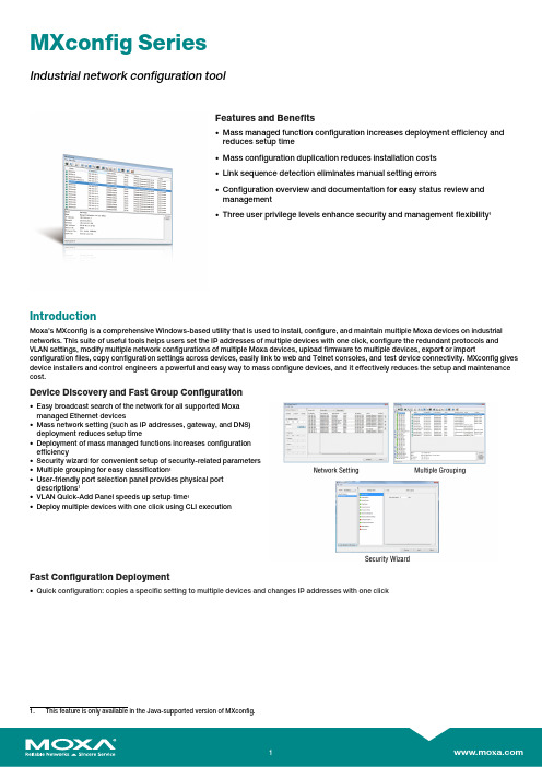
MXconfig SeriesIndustrial network configuration toolFeatures and Benefits•Mass managed function configuration increases deployment efficiency andreduces setup time•Mass configuration duplication reduces installation costs•Link sequence detection eliminates manual setting errors•Configuration overview and documentation for easy status review andmanagement•Three user privilege levels enhance security and management flexibility1IntroductionMoxa’s MXconfig is a comprehensive Windows-based utility that is used to install,configure,and maintain multiple Moxa devices on industrial networks.This suite of useful tools helps users set the IP addresses of multiple devices with one click,configure the redundant protocols and VLAN settings,modify multiple network configurations of multiple Moxa devices,upload firmware to multiple devices,export or import configuration files,copy configuration settings across devices,easily link to web and Telnet consoles,and test device connectivity.MXconfig gives device installers and control engineers a powerful and easy way to mass configure devices,and it effectively reduces the setup and maintenance cost.Device Discovery and Fast Group Configuration•Easy broadcast search of the network for all supported Moxamanaged Ethernet devices•Mass network setting(such as IP addresses,gateway,and DNS)deployment reduces setup time•Deployment of mass managed functions increases configurationefficiency•Security wizard for convenient setup of security-related parameters•Multiple grouping for easy classification1•User-friendly port selection panel provides physical portdescriptions1•VLAN Quick-Add Panel speeds up setup time1•Deploy multiple devices with one click using CLI executionFast Configuration Deployment•Quick configuration:copies a specific setting to multiple devices and changes IP addresses with one clickLink Sequence Detection•Link sequence detection eliminates manual configuration errorsand avoids disconnections,especially when configuringredundancy protocols,VLAN settings,or firmware upgrades for anetwork in a daisy-chain topology (line topology).•Link Sequence IP setting (LSIP)prioritizes devices and configuresIP addresses by link sequence to enhance deployment efficiency,especially in a daisy-chain topology (linetopology).Unlock Devices and User Privileges•Mass device unlocking and password file export for quick unlocks.•Three user privilege levels to enhance management flexibility and security:Admin,Supervisor,and Operator.2Configuration Overview and Documentation•Useful mass status overview and configuration check for eachmanaged function.•Generate reports on each managed function for multiple devices inthe network.2•Export multiple configuration files with flexible filenames and import multiple configuration files to multiple devices.•Export device list for easy backup,and import device list for quick searching2SpecificationsHardware RequirementsRAM2GB Hardware Disk Space10GB OSWindows 7(32/64-bit),Windows 10(32-64-bit),Windows Server 2012(32/64-bit)CPU 2GHz or faster dual-core CPUSupported DevicesAWK Products MXconfig Java Version:AWK-1121Series(v1.4or higher)AWK-1127Series(v1.4or higher)AWK-1131A Series(v1.11or higher)AWK-1137C Series(v1.3or higher)AWK-3121Series(v1.10or higher)AWK-3121-SSC-RTG Series(v1.4or higher)AWK-3121-M12-RTG Series(v1.4or higher)AWK-3131Series(v1.2or higher)AWK-3131-M12-RCC Series(v1.0or higher)AWK-3131A Series(v1.3or higher)AWK-3131A-RTG Series(v1.8or higher)AWK-4121Series(v1.10or higher)AWK-4131Series(v1.2or higher)AWK-4131A Series(v1.3or higher)AWK-5222Series(v1.7or higher)AWK-5232Series(v1.3or higher)AWK-6222Series(v1.7or higher)AWK-6232Series(v1.3or higher)EDR Products MXconfig Java Version:EDR-810Series(v3.2or higher)EDR-G902Series(v4.2or higher)EDR-G903Series(v4.2or higher)MXconfig Non-Java Version:EDR-810Series(v3.2or higher)EDR-G902Series(v4.2or higher)EDR-G903Series(v4.2or higher)EDR-G9010Series(v1.0or higher)EDS Products MXconfig Java Version:EDS-405A/408A Series(v3.1or higher)EDS-405A/408A-EIP Series(v3.1or higher)EDS-405A/408A-PN Series(v3.1or higher)EDS-405A-PTP Series(v3.3or higher)EDS-505A/508A/516A Series(v3.1or higher)EDS-510A Series(v3.1or higher)EDS-518A Series(v3.1or higher)EDS-510E/518E Series(v4.0or higher)EDS-528E Series(v5.0or higher)EDS-G508E/G512E/G516E Series(v4.0or higher)EDS-G512E-8PoE Series(v4.0or higher)EDS-608/611/616/619Series(v3.1or higher)EDS-728Series(v3.1or higher)EDS-828Series(v3.1or higher)EDS-G509Series(v3.1or higher)EDS-P510Series(v3.1or higher)EDS-P510A-8PoE Series(v3.1or higher)EDS-P506A-4PoE Series(v3.1or higher)EDS-P506E-4PoE Series(v5.5or higher)MXconfig Non-Java Version:EDS-405A/408A Series(v3.1or higher)EDS-405A/408A-EIP Series(v3.1or higher)EDS-405A/408A-PN Series(v3.1or higher)EDS-405A-PTP Series(v3.3or higher)EDS-505A/508A/516A Series(v3.1or higher)EDS-510A Series(v3.1or higher)EDS-518A Series(v3.1or higher)EDS-510E/518E Series(v4.0or higher)EDS-528E Series(v5.0or higher)EDS-G508E/G512E/G516E Series(v4.0or higher)EDS-G512E-8PoE Series(v4.0or higher)EDS-608/611/616/619Series(v3.1or higher)EDS-728Series(v3.1or higher)EDS-828Series(v3.1or higher)EDS-G509Series(v3.1or higher)EDS-P510Series(v3.1or higher)EDS-P510A-8PoE Series(v3.1or higher)EDS-P506A-4PoE Series(v3.1or higher)EDS-P506E-4PoE Series(v5.5or higher)ICS Products MXconfig Java Version:ICS-G7526/G7528Series(v3.1or higher)ICS-G7826/G7828Series(v3.1or higher)ICS-G7748/G7750/G7752Series(v3.1or higher)ICS-G7848/G7850/G7852Series(v3.1or higher)ICS-G7526A/G7528A Series(v4.0or higher)ICS-G7826A/G7828A Series(v4.0or higher)ICS-G7748A/G7750A/G7752A Series(v4.0or higher)ICS-G7848A/G7850A/G7852A Series(v4.0or higher)MXconfig Non-Java Version:ICS-G7826/G7828Series(v3.1or higher)ICS-G7748/G7750/G7752Series(v3.1or higher)ICS-G7848/G7850/G7852Series(v3.1or higher)ICS-G7526A/G7528A Series(v4.0or higher)ICS-G7826A/G7828A Series(v4.0or higher)ICS-G7748A/G7750A/G7752A Series(v4.0or higher)ICS-G7848A/G7850A/G7852A Series(v4.0or higher) IEX Products MXconfig Java Version:IEX-402Series(v1.0or higher)IEX-408E Series(v4.0or higher)MXconfig Non-Java Version:IEX-402Series(v1.0or higher)IEX-408E Series(v4.0or higher)IKS Products MXconfig Java Version:IKS-6726/6728Series(v3.1or higher)IKS-G6524Series(v3.1or higher)IKS-G6824Series(v3.1or higher)IKS-6728-8PoE Series(v3.1or higher)IKS-6726A/6728A Series(v4.0or higher)IKS-G6524A Series(v4.0or higher)IKS-G6824A Series(v4.0or higher)IKS-6728A-8PoE Series(v4.0or higher)MXconfig Non-Java Version:IKS-6726/6728Series(v3.1or higher)IKS-G6524Series(v3.1or higher)IKS-G6824Series(v3.1or higher)IKS-6728-8PoE Series(v3.1or higher)IKS-6726A/6728A Series(v4.0or higher)IKS-G6524A Series(v4.0or higher)IKS-G6824A Series(v4.0or higher)IKS-6728A-8PoE Series(v4.0or higher)ioLogik Products MXconfig Java Version:ioLogik E1200Series(v3.2or higher)ioThinx Products MXconfig Java Version:ioThinx4510Series(v1.3or higher)MDS Products MXconfig Java Version:MDS-G4012Series(v1.1or higher)MDS-G4020Series(v1.1or higher)MDS-G4028Series(v1.1or higher)MXconfig Non-Java Version:MDS-G4012Series(v1.1or higher)MDS-G4020Series(v1.1or higher)MDS-G4028Series(v1.1or higher)MDS-G4012-L3Series(v2.0or higher)MDS-G4020-L3Series(v2.0or higher)MDS-G4028-L3Series(v2.0or higher)MGate Products MXconfig Java Version:MGate MB3170/MB3270Series(v4.2or higher)MGate MB3180Series(v2.2or higher)MGate MB3280Series(v4.1or higher)MGate MB3480Series(v3.2or higher)MGate MB3660Series(v2.5or higher)MGate EIP3270Series(v2.0or higher)MGate5101-PBM-MN Series(v2.2or higher)MGate5102-PBM-PN Series(v2.3or higher)MGate5103Series(v2.2or higher)MGate5105-MB-EIP Series(v4.3or higher)MGate5108Series(v2.4or higher)MGate5208Series(v2.4or higher)MGate5109Series(v2.3or higher)MGate5111Series(v1.3or higher)MGate5114Series(v1.3or higher)MGate5118Series(v2.2or higher)MGate5217Series(v1.0or higher)NPort Products MXconfig Java Version:NPort S8000Series(v1.3or higher)NPort S9000Series(v1.0or higher)NPort5110Series(v3.8or higher)NPort5130/5150Series(v3.8or higher)NPort5000AI-M12Series(v1.4or higher)NPort5200Series(v2.10or higher)NPort5400Series(v3.13or higher)NPort5600Series(v3.9or higher)NPort5100A Series(v1.5or higher)NPort5200A Series(v1.5or higher)NPort5610-8-DT/5610-8-DT-J/5650-8-DT/5650I-8-DT/5650-8-DT-J Series(v2.6orhigher)NPort5610-8-DTL/5650-8-DTL/5650I-8-DTL Series(v1.5or higher)NPort IA5000Series(v1.6or higher)NPort IA5150A/IA5150AI/IA5250A/IA5250AI Series(v1.4or higher)NPort IA5450A/IA5450AI Series(v1.6or higher)NPort6000Series(v1.21or higher)PT Products MXconfig Java Version:PT-7528Series(v3.1or higher)PT-7710Series(v3.1or higher)PT-7728Series(v3.1or higher)PT-7828/7828-PTP Series(v3.1or higher)PT-G7509Series(v3.1or higher)PT-508/510Series(v3.1or higher)PT-G7728Series(v5.4or higher)PT-G7828Series(v5.4or higher)MXconfig Non-Java Version:PT-7528Series(v3.1or higher)PT-7710Series(v3.1or higher)PT-7728Series(v3.1or higher)PT-7828/7828-PTP Series(v3.1or higher)PT-G7509Series(v3.1or higher)PT-508/510Series(v3.1or higher)PT-G7728Series(v5.4or higher)PT-G7828Series(v5.4or higher)SDS Products MXconfig Non-Java Version:SDS-3008Series(v2.1or higher)SDS-3016Series(v2.1or higher)TAP Products MXconfig Java Version:TAP-213Series(v1.2or higher)TAP-323Series(v1.8or higher)TN Products MXconfig Java Version:TN-4500A Series(v3.5or higher)TN-5508/5510Series(v3.1or higher)TN-5516/5518Series(v3.1or higher)TN-5916Series(v1.2or higher)MXconfig Non-Java Version:TN-4500A Series(v3.5or higher)TN-4908Series(v1.0or higher)TN-5508/5510Series(v3.1or higher)TN-5516/5518Series(v3.1or higher)TN-5916Series(v1.2or higher)VPort Products MXconfig Java Version:VPort26A-1MP Series(v1.2or higher)VPort36-1MP Series(v1.1or higher)VPort P06-1MP-M12Series(v2.2or higher)WAC Products MXconfig Java Version:WAC-1001Series(v2.1or higher)WAC-2004Series(v1.6or higher)©Moxa Inc.All rights reserved.Updated Jan04,2022.This document and any portion thereof may not be reproduced or used in any manner whatsoever without the express written permission of Moxa Inc.Product specifications subject to change without notice.Visit our website for the most up-to-date product information.。
KNX IP 路由器使用手册说明书

K-BUS ®KNX IP 路由器KNX IP Router_V1.3BNIPR-00/00.1KNX/EIB 住宅和楼宇智能控制系统使用手册目录第一章概述------------------------------------------------------------------------------------------------------------------------------------------------1 1.1.功能概述------------------------------------------------------------------------------------------------------------------------------------------1 1.2.通道------------------------------------------------------------------------------------------------------------------------------------------------2 1.3.路由------------------------------------------------------------------------------------------------------------------------------------------------2 1.4.KNX IP路由器-----------------------------------------------------------------------------------------------------------------------------------3第二章技术参数&尺寸图和操作指示--------------------------------------------------------------------------------------------------------------3 2.1.技术参数------------------------------------------------------------------------------------------------------------------------------------------3 2.2.尺寸图(单位:mm)---------------------------------------------------------------------------------------------------------------------------4 2.3.指示和操作功能---------------------------------------------------------------------------------------------------------------------------------5第三章项目设计和应用--------------------------------------------------------------------------------------------------------------------------------6 3.1.操作模式------------------------------------------------------------------------------------------------------------------------------------------63.1.1.LED指示------------------------------------------------------------------------------------------------------------------------------------63.1.2.功能按钮------------------------------------------------------------------------------------------------------------------------------------63.1.3.编程按钮和LED--------------------------------------------------------------------------------------------------------------------------6 3.2.IP路由应用---------------------------------------------------------------------------------------------------------------------------------------73.2.1.IP网络中的KNX报文------------------------------------------------------------------------------------------------------------------73.2.2.IP路由器在网络安装中------------------------------------------------------------------------------------------------------------------73.2.3.IP路由器作为域耦合器使用-----------------------------------------------------------------------------------------------------------83.2.4.IP路由器使用在混合系统中-----------------------------------------------------------------------------------------------------------83.2.5.IP路由器作为线耦合器使用-----------------------------------------------------------------------------------------------------------9第四章ETS中系统参数设置说明-------------------------------------------------------------------------------------------------------------------104.1.物理地址配置----------------------------------------------------------------------------------------------------------------------------------10 4.2.参数界面“General”-----------------------------------------------------------------------------------------------------------------------11 4.3.参数界面“IP configuration”-------------------------------------------------------------------------------------------------------------12 4.4.参数界面“KNX Multicasting Address”----------------------------------------------------------------------------------------------13 4.5.参数界面“Main Line”---------------------------------------------------------------------------------------------------------------------14 4.6.参数界面“Sub Line”----------------------------------------------------------------------------------------------------------------------15第五章网页配置----------------------------------------------------------------------------------------------------------------------------------------17 5.1.访问网页端的方式----------------------------------------------------------------------------------------------------------------------------175.1.1.通过windows网络访问---------------------------------------------------------------------------------------------------------------175.1.2.通过IP地址访问------------------------------------------------------------------------------------------------------------------------185.1.3.通过MAC地址访问--------------------------------------------------------------------------------------------------------------------18 5.2.设备信息-----------------------------------------------------------------------------------------------------------------------------------------19 5.3.KNX-----------------------------------------------------------------------------------------------------------------------------------------------19 5.4.Update--------------------------------------------------------------------------------------------------------------------------------------------20 5.5.IP tunneling地址分配------------------------------------------------------------------------------------------------------------------------23第六章出厂状态----------------------------------------------------------------------------------------------------------------------------------------25第一章概述IP路由器可用作线耦合器或骨干耦合器。
工业物联网智能网关参数说明

2020
谢谢观赏
工业物联网智能网关
我们自主研发的SP-WG200BN网关,采用业内工业级高性能嵌入式结构,针对智能制造、智能家居、智慧农场、工 业控制、工厂设备等领域,将数据的采集与传输做了专业的一体化设计。使用此网关时,用户无需关心具体细节,只需 简单设置即可实现以太网、WIFI、RS232、RS485、RF433、IO等设备之间的数据交换。网关自带输入输出、AD采集和 温度测量等功能,用户发送简单指令即可方便采集设备的开关信号、计数信号、模拟量信号,也可以控制设备的输出状 态。
数据传输拓扑图
本网关支持MQTT协议,可选择使用有 线、WiFi或者NB-IoT接入MQTT服务 器。网关根据配置好的上传周期,定 时将设备的传输状态、计数、AD采集 值、温度等数据打包成JSON格式上传 到 M Q T T 服 务 器 。 还 支 持 使 用 AT 指 令 发布主图。
工业网关-产品细节说明
从一定意义上来讲NB-IoT也不例外。从出世以来,关 于NB-IoT的讨论,从来都没有间断过。
经过几年的发展,数据证明,NB-IoT的发展态势迅猛, 质疑声渐小。
NB-IoT具有大连接、广覆盖、低功耗等特点,迎合了 70%以上的物联网场景的需求。
物联网网关应用
在数字经济大发展的大背景下,过去3 年,NB-IoT实现跨越式发展,已在多 个行业实现规模化落地。目前,NBIoT已深入40多个行业,诞生了包括水 表、电表等4个千万级应用,近10个包 括智能家电、门锁在内的百万级应用, 以及层出不穷的新兴行业应用。
工业物联网 智能网关
RS485/无线/RS232/IO信号数据采集
讯鹏科技
2020.07.17
工业物联网智能网关介绍
随着智能城市、大数据时代的来临,无线通信将实现万物连接。很多企业预计未来全球物联网连接数将是千亿级的 时代。已经出现了大量物与物的联接, 然而这些联接大多通过蓝牙、Wi-Fi等短距通信技术承载,但非运营商移动网络。 为了满足不同物联网业务需求,根据物联网业务特征和移动通信网络特点,3GPP根据窄带业务应用场景开展了增强移动 通信网络功能的技术研究以适应蓬勃发展的物联网业务需求。
1.0 Smart Home Controller 快速安装手册说明书
Smart Home ControllerQuick Installation ManualTable of contents1.Introduction (4)1.1.Safety instructions (4)1.2.Intended use (4)1.3.About this document (4)1.3.1.How to start (4)1.3.2.Troubleshooting (4)1.3.3.Feedback (4)2.Installation (5)2.1.Smart Home Controller Installation (5)2.2.MRF xComfort Network Installation (5)3.Quick setup (7)3.1.Connect to the Web Admin Console (7)3.2.Import Data Points (8)3.3.Adjust available Devices (8)3.4.Create Users (10)3.5.Set Time Zone (11)3.6.Activate the Smart Home Controller (12)3.7.Create Zones and assign available Devices (13)3.8.Enable and setup needed Functions (14)3.9.Download and connect the App (IOS) (15)3.10.IOS App: Start the Temperature Control (16)3.11.IOS App: Create Light Scenes (17)4.Troubleshooting (18)4.1.LED Indicators on the Smart Home Controller Box (18)4.2.How to restore the default admin password (18)4.3.How to restore the SHC network settings (19)4.4.Ways to recover the SHC (19)4.5.Ways to connect to the SHC Web Admin Console (19)4.5.1.Directly via a browser and IP address (19)4.5.2.Via Bonjour (MAC) (19)4.5.3.Via UPnP (Windows) (20)4.5.4.Via MRF (20)4.6.Default admin password? (20)Appendix A Feedback form (21)1. Introduction1.1. Safety instructionsThis document contains important warnings and safety instructions which must be observed and followed by users. Failure to follow these warnings and safety instructions will put the fault-free operation of the Smart Home Controller at risk.1.2. Intended usexComfort products are designed for use in private homes and similar, fixed electrical installation systems. Applicable standards can be found in the CE declarations of conformity included in the mounting instructions supplied with each product.1.3. About this documentThis manual is intended for trained Installers only and describes the installation and configuration of the Smart Home Controller. Following this manual will ensure a successful installation1.3.1. How to startIf you are new to the System, start with the chapter “How things work” in the Smart Home Controller Reference Manual to understand the Smart Home Controller concept and basics. Important is to know how this system works based on Zones and the way functionality is provided. This will directly affect the way the User can control his home.If you are already familiar with the system, start directly with chapter 2 Installation and 3 Quick setup.1.3.2. TroubleshootingIn case of problems check chapter 4 Troubleshooting.1.3.3. FeedbackPlease feel free to support us with any suggestions or feedback. Please use the feedback form in appendix A.2. InstallationFollow the instructions in this chapter to install the Smart Home Controller and setup the xComfort network.Installation steps:• Smart Home Controller Installation• MRF xComfort network Installation2.1. Smart Home Controller InstallationFind an appropriate location for the Smart Home Controller. This location must be dry and free of other electric equipment that could disturb the working of the Controller. Keep in mind that the SHC does have an internal antenna for the xComfort RF network.ATTENTION! Find an appropriate location for the SHC. The SHC does have aninternal antenna for the xComfort RF module. Avoid disturbance from other equipment like WiFi routers. Minimum distance > 0,5m.Installation steps:1. Use the mounting holes in the SHC to screw the SHC to the wall.2. Connect the SHC to your home network using a network cable.3. Connect the power adapter to the SHC and switch on the power.2.2. MRF xComfort Network InstallationUse the MRF xComfort Network Configuration Tool to create and setup the xComfort Network and create a Datapoint file so that the SHC recognizes all the xComfort Devices in the network.ATTENTION! Use MRF tool version or higher: Eaton RF-System V2.19.Installation steps:1. Make a plan of all the functionality in Zones needed.2. Open the MRF Tool and create the MRF project.3. Scan the network for xComfort Devices.4. Configure the Device Settings if needed.Checklist:Door (Switch) Actuator: Function: Off / On with switch off delay. Shutter Actuator: Runtime. Dimming Actuator: Dimming time, Dimming limits. Binary Inputs: Mode 2, Cyclic sending.Analog Inputs: 0 – 10V, Cyclic sending.Temperature Sensors: Send Temperature value, Cyclic sending. By default the Climate Function expects within every hour a temperature value. Set cyclic sendingvalue to 55 minutes.5. Connect all xComfort Devices to the Smart Home Controller. See Figure 1: MRF Projectexample.ATTENTION! To maintain the correct status of the Actuators it is important toconnect all xComfort Actuators directly to the Smart Home Controller or an ECI. Find detailed information in the Smart Home Controller Reference Manual.6. Specify a clear name for each Device.7. Scan reception quality of all devices. Calculate and check all connections.8. Load the configuration into the devices.9. Create datapoint-file for the SHC and select Transmission: download by RF.10. Save project.Figure 1: MRF Project example3. Quick setupFollow the instructions in this chapter to do a quick setup of the Smart Home Controller with a basic configuration. Find additional information and configurations in the Smart Home Controller Reference Manual.Setup steps:Connect to the SHC Web Admin ConsoleImport Data PointsAdjust available DevicesCreate UsersSet Time ZoneActivate the Smart Home ControllerCreate Zones and assign available DevicesEnable and setup needed FunctionsDownload and connect the App (IOS)IOS App Function settings3.1. Connect to the Web Admin ConsoleConnect to the Web Admin Console via MRF.Steps:1. Open MRF and load the project2. Right click on the SHC and select: IP-Address3. Click on the link: Address4. The browser opens with the login page:5. Login with:- Username: admin- Password: admin6. The Web Admin Console is available3.2. Import Data PointsDuring the Installation the Data Points are already uploaded to the Smart Home Controller via MRF. If not, check chapter 2.2 MRF xComfort Network Installation.Admin Console navigation: 1. System -> DatapointsSetup steps:1. The default Internal RF Interface indicates the new datapoints:2. Click: Import Data Points3. Please wait until the popup shows the process is ready:ATTENTION! Do not interrupt this step.4. Click: OK5. Status indicates:3.3. Adjust available DevicesChange the name and purpose of imported devices if needed. Specify always the unit and ratio for Impulse Counters and Analog Inputs.Web Admin Console navigation: 1. System -> DevicesSteps:1. Select one Device of the available Devices on the left. Example:2. Change the Device parameters on the right. Example:3. Click: Save4. Repeat previous steps for each Device5. If finished, Click:6. Please wait until the popup shows the process is ready:ATTENTION! Do not interrupt this step.7. Click: OK3.4. Create UsersWeb Admin Console navigation: 1. System -> UsersFirst: Change always the default admin password!Steps to change the admin password:1. Click for User admin the Change Password Icon:2. Change and remember the password:3. Click: Ok4. Change the language if needed (Used for the Admin Console)Add at least one Advanced User:1. Specify User credentials:2. Click: Add3. The new User is shown in the list of UsersCheck options: Advanced and: RemoteAdd at least one normal User to control the system:1. Specify User credentials:2. Click: Add3. The new User is shown in the list of UsersIf needed check option: Remote3.5. Set Time ZoneWeb Admin Console navigation: 1. System -> Time Zone Steps:1. Check Time Zone Settings:2. Change settings if needed. Normally: Country and: City3. Click: Save3.6. Activate the Smart Home ControllerActivate the SHC for remote access and new software updates.Admin Console navigation: 1. System -> Remote AccessSteps:1. Check if there is Internet Access:2. Click: Activate:3. Read and Accept the Terms And Conditions: Accept4. Please wait until the popup disappears:5. Enable: Global Remote Access6. Refresh the page to check the connection status:7. Please make a note of the received Remote Access ID to connect remotely3.7. Create Zones and assign available DevicesAs defined by the Customer create the Zones and add the Devices to these Zones. Create general Zones if needed.Web Admin Console navigation: 2. ZonesSteps:1. Click: New2. Define a Zone name:3. Click: OK4. Select one or more Available Devices on the right side (Hold shift or ctrl):5. Click to add the selected Devices to the Zone:6. Added Devices are shown in the left screen:7. Repeat all steps for each Zone3.8. Enable and setup needed FunctionsEnable the Functions required by the Customer in each Zone.Web Admin Console navigation: 3. FunctionsSteps:1. Select the Zone (Per default the Functions are disabled):2. Enable the required Functions for this Zone (Function properties appears):3. Adjust specific properties if needed4. Repeat all steps for each Zone3.9. Download and connect the App (IOS)This example is based on the iPhone.Figure 2: Download AppOpen the App Store: Search for: EatonInstall and open the AppFigure 3: Connect to Smart Home ControllerClick: ConnectSelect your controllerLogin as advanced User3.10. IOS App: Start the Temperature ControlSelect the Climate Function:Figure 4: Start the Temperature ControlSelect a predefined mode Click: Edit Select: HeatingAnd: CloseThe question mark indicates that no temperature value has been received yet. For additional information see the Smart Home Controller Reference Guide. Start the Temperature Control in every Zone with a Climate Function via the “edit” button.3.11. IOS App: Create Light ScenesTo create a Light Scene, select the Status & Control Function to set the preferred light settings.Figure 5: Create a Light Scene 1Select Status & Control Set preferred LightsSelect Scene FunctionAnd click: EditClick:Figure 6: Create a Light Scene 2Define a Scene nameAnd click: OKCheck light settings And return to Zone Button created4. TroubleshootingFind in this chapter information and instructions to solve problems. Consult also the latest FAQ to find answers to questions.4.1. LED Indicators on the Smart Home Controller BoxPower LED:o Green: Power ON, the System is operational.o Orange: The System is booting.Network Connection LED:o Green: Remote Server Connection.o Orange: Internet connection. The SHC is not activated yet.o Red: No Internet connection. Check your internet connection via a PC or laptop.RF Traffic LED:o Blinking Green: RF traffic.System Message LED:o Green: There are no new messages in the Mailbox.o Yellow: New Warning Message in the Mailbox.o Red: New Error Messages in the Mailbox.Battery Status LEDo Green: All batteries are OK.o Yellow: At least one battery is weak. Consider to replace batteries.o Red: At least one battery one battery is very weak or empty. Replace batteries.4.2. How to restore the default admin passwordThis symbol indicates the recovery button on the Smart Home Controller Box.Use a small pin to access this button.Press the button on the Smart Home Controller for 15 seconds (power LED flashes green and will finally change to orange), system will reboot. Wait until the LED is green. Also the network settings will be set to DHCP.4.3. How to restore the SHC network settingsThis symbol indicates the recovery button on the Smart Home Controller Box.Use a small pin to access this button.Press the button on the Smart Home Controller for 15 seconds (power LED flashes green and will finally change to orange), system will reboot. Wait until the LED is green. Also the admin password is set to default.4.4. Ways to recover the SHCThe Smart Home Controller can be recovered in the following ways:•Power Off the System by removing the power plug for 1 minute and reconnect.•Reboot the Smart Home Controller via the Web Admin Console.•Set the Smart Home Controller back to factory settings. Reconfigure everything.•Reset internal RF Module password and datapoint list. Use MRF to reprogram. Admin Console navigation: 1. System -> Firmware4.5. Ways to connect to the SHC Web Admin Console4.5.1. Directly via a browser and IP address1. Open a browser2. Open the login page: http://<SHC IP address>:3. Login with:- Username: admin- Password: admin4. The Web Admin Console is available4.5.2. Via Bonjour (MAC)1. Open: Safari2. Click the Bookmark icon:3. Select Bonjour:4. Double click Bookmark: Smart Home Controller5. The browser opens with the login page4.5.3. Via UPnP (Windows)1. Open My Network Places:2. Double click link: Smart Home Controller3. The browser opens with the login page4.5.4. Via MRF1. Open MRF and right-click on the SHC:2. Select Check IP-Address3. Click on the Address4. The browser opens with the login page4.6. Default admin password?The default password for admin is admin. Please change this password directly after the setup.4.7. Diagnostics Status bar: Indicators and colorsIn the top bar the following status indicators are shown:Network status:o Green: Connected to the Remote Servero Yellow: Connected to Interneto Red: No Internet connectionBattery status battery powered Devices:o Green: All batteries are goodo Yellow: One or more batteries are weako Red: One or more batteries are emptyRF Interface status:o Green: All configured Interfaces are upo Red: One or more Interfaces are downNew Messages available:o Green: No new messages after the last checko Yellow: New Warning messageso Red: New Error messagesQuick Installation ManualPage 21 of 21 Appendix A Feedback formUse this feedback form below to send us your comments. We read all feedback carefully, but please note that we cannot respond to the comments you submit.Please send your feedback to your local sales contact.Name: ……………………………………………..Email Address: ……………………………………………..Used Smartphone, Tablet and browsers:iPhone App iOS Version:…………………………………………… iPad App iOS Version:…………………………………………… Andoid Phone App Android Version:………………………………………. Andoid Pad App Android Version:………………………………………. Safari Browser Version:………………………………………………….Google Chrome BrowserVersion:…………………………………………………. Mozilla Firefox Browser Version:…………………………………………………. Internet Explorer Browser Version:…………………………………………………. Other: ……………………………………………..Feedback Type:Bug Report Language-Specific Bug/IssueDesign/Ease of Use Missing/New FunctionalityConnectivity/Remote Server ConfigurabilitySmall description of the installation and building:Comments:。
MOXA OnCell G3101 G3201系列多频谐波GSM GPRS IP网关功能与优势说明书

OnCell G3101/G3201SeriesCompact quad-band GSM/GPRS IP gatewaysFeatures and Benefits•Universal quad-band GSM/GPRS850/900/1800/1900MHz•Desktop or DIN-rail installation•Connect Ethernet and serial devices•Centralized private IP management software with OnCell Central Manager•Choice of configuration methods,including web console,serial console,andTelnetCertificationsIntroductionThe OnCell G3111/G3151/G3211/G3251are cellular IP gateways that can conveniently and transparently connect up to two devices to a cellular network,allowing you to connect serial devices to your existing Ethernet with only basic configuration.To ensure zero data loss and on-demand cellular communication,OnCell devices are integrated with the GuaranLink function.The G3111/G3151/G3211/G3251cellular IP gateways are compact,and can be placed on a desk or mounted on a DIN rail.The products come with a12to48VDC power input and have2kV EFT/surge protection to allow the use of different types of field power sources.The serial ports are also protected by15kV ESD line protection to keep your system safe from unexpected electrical discharges.SpecificationsCellular InterfaceCellular Standards GSM,GPRSBand Options Quad-band GSM/GPRS850MHz/900MHz/1800MHz/1900MHzGPRS Data Rates85.6kbps DL,43kbps ULGPRS Multi-Slot Class10GPRS Terminal Device Class Class BGPRS Coding Schemes CS1to CS4Cellular Antenna Connectors1SMA femaleNo.of SIMs1SIM Control Voltage3VEthernet Interface10/100BaseT(X)Ports(RJ45connector)1Total Port Count1Ethernet Software FeaturesManagement ARP,DDNS,DHCP/BOOTP,DNS Relay,HTTP,SMTP,SNMPv1/v2c/v3,TCP/IP,Telnet,UDP,Web Console,Wireless Search Utility,Serial Console,Telnet Console,RemoteSMS Control,OnCell Central Manager,GuaranLinkRouting NAT,Port forwarding,WAN IP FilteringSecurity HTTPS/SSL,SSHTime Management SNTPFirewallFilter ICMPSerial InterfaceSerial Standards OnCell G3211/G3111:RS-232OnCell G3151/G3251:RS-232/422/485Data Bits5,6,7,8Stop Bits1,1.5,2Parity None,Even,Odd,Space,MarkFlow Control RTS/CTS,XON/XOFFBaudrate50bps to921.6kbpsSerial SignalsRS-232TxD,RxD,RTS,CTS,DTR,DSR,DCD,GNDRS-422Tx+,Tx-,Rx+,Rx-,GNDRS-485-2w Data+,Data-,GNDRS-485-4w Tx+,Tx-,Rx+,Rx-,GNDOperation ModesStandards Ethernet Modem modeReal COM modeRFC2217modeTCP Client modeTCP Server modeUDP modeSMS TunnelReverse Real COMPower ParametersInput Voltage12to48VDCPower Connector Power jackInput Current0.9A@12VDC,0.23A@48VDCPhysical CharacteristicsHousing AluminumIP Rating IP30Dimensions77x111x26mm(3.03x4.37x1.02in)Weight OnCell G3151/G3111:170g(0.38lb)OnCell G3211/G3251:190g(0.42lb)Environmental LimitsOperating Temperature-30to55°C(-22to131°F)Storage Temperature(package included)-40to75°C(-40to167°F)Ambient Relative Humidity5to95%(non-condensing)Standards and CertificationsSafety UL60950-1EMC EN55032/24EMI CISPR32,FCC Part15B Class AEMS IEC61000-4-2ESD:Contact:8kV;Air:15kVIEC61000-4-3RS:80MHz to1GHz:10V/mIEC61000-4-4EFT:Power:4kV;Signal:2kVIEC61000-4-5Surge:Power:1kV;Signal:1kVIEC61000-4-6CS:10VIEC61000-4-8PFMFRadio Frequency FCC Part22H,FCC Part24E,EN301489-1,EN301489-7,EN301511,PTCRB(OnCellG3151only)MTBFTime1,483,420hrsStandards Telcordia SR332WarrantyWarranty Period5yearsDetails See /warrantyPackage ContentsDevice1x OnCell G3101/G3201Series IP gateway1Installation Kit1x DIN-rail kit1x rubber standAntenna1x GSM/GPRSPower Supply DC power supply(screw-on type)Documentation1x quick installation guide1x warranty card1.An activated SIM card(not included)must be provided by a third party Cellular Service Provider.DimensionsOrdering InformationModel Name Cellular Standard GPRS Band Operating Temp.No.of Serial Ports Serial StandardsOnCell G3111GSM/GPRS 850/900/1800/1900MHz-30to55°C1RS-232OnCell G3151GSM/GPRS 850/900/1800/1900MHz-30to55°C1RS-232/422/485OnCell G3211GSM/GPRS 850/900/1800/1900MHz-30to55°C2RS-232OnCell G3251GSM/GPRS 850/900/1800/1900MHz-30to55°C2RS-232/422/485Accessories(sold separately)Wireless Antenna CablesA-CRF-SMSF-R3-100Cellular magnetic-base SMA connector with1-meter RF cable©Moxa Inc.All rights reserved.Updated Aug29,2019.This document and any portion thereof may not be reproduced or used in any manner whatsoever without the express written permission of Moxa Inc.Product specifications subject to change without notice.Visit our website for the most up-to-date product information.。
零海拔 FXS网关使用说明V1.0说明书

FXS网关使用说明V1.0深圳市零海拔科技有限公司Marketing@Support@2010-6-7目录1.概要 (1)1.1. 简介 (1)1.2. 协议 (1)1.3. 硬件特性 (2)1.4. 软件特性 (2)1.5. 产品包装清单 (2)1.6. 产品外观 (3)2.连接说明 (5)2.1. 接口说明: (5)2.2. 显示灯说明: (7)2.3. 连接图: (8)3.开始配置 (10)3.1. 出厂设置参数 (10)3.2. 电话操作的星号命令 (11)3.3. 呼叫 (12)3.3.1. 拔打电话本号码 (12)3.4. 登陆到网关 (12)3.4.1. 获取IP (12)3.4.2. 打开浏览器输入IP (12)3.5. 配置网关 (14)3.5.1. 用户选项 (14)3.5.2.网络配置 (18)3.5.3.呼叫设置 (20)3.5.3.1. H.323 终端配置 (20)3.5.3.2. 直连模式 (21)3.5.3.3. 关守模式 (21)3.5.3.4. 加密 (25)3.5.3.5. H.323高级设置 (25)3.5.3.6. SIP协议 (27)3.5.3.7. 防火墙穿越 (36)3.5.4. 话机设置 (39)3.5.5. 保存改动: (40)3.5.6. 放弃改动: (40)4.电话本 (41)5.工具 (42)5.1. 在线升级 (42)5.2. 更改密码 (42)5.3. 恢复出厂设置 (43)5.4. 重启系统 (43)6.拨号规则 (43)6.1. 基本规则语法: (44)6.2. 带号码位数限制的拨号规则 (45)7.了解更多 (45) FXS系列网关说明书1.概要1.1. 简介FXS系列网关是零海拔科技开发的高性能宽带网关,用于将模拟电话连接到VOIP网络电话系统或VOIP服务提供商。
FXS系列网关内置H.323与SIP协议,高可靠的线路检测功能最高限度地防止线路挂死。
智能3路开关套装用户指南 HS210 KIT 1910012319 REV1.0.0说明书
User GuideSmart Wi-Fi Light Switch, 3-Way KitHS210 KIT1910012319 REV1.0.0ContentsAbout This Guide (1)Introduction (2)Appearance (3)Set Up Y our Smart 3-Way Switch Kit (4)Main Pages (6)Configure Your Smart 3-Way Switch Kit (7)Create Scenes (9)Connect to Amazon Alexa or Google Home (10)Authentication (11)About This GuideThis guide provides a brief introduction to Smart 3-Way Switch Kit and the Kasa app, as well as regulatory information.Please note that features of Smart 3-Way Switch Kit may vary slightly depending on the model and software version you have, and on your location, language and internet service provider. All images, parameters and descriptions documented in this guide are used for demonstration only.ConventionsMore Info• Specifications can be found on the product page at .• Our T echnical Support and troubleshooting information can be found at /support.12Introduction 3-Way Switching, where a light is controlled from two switch locations, is common in hallways, stairs, and living rooms. 3-Way Switch wiring can be complex, but TP-Link’s Smart 3-Way Switch Kit makes it an easy smart home upgrade and provides control from anywhere, scheduling, and much more. The Kit includes 2 smart switches specially designed for 3-way switch wiring. The free Kasa app provides step-by-step instructions for wiring your switches and connecting them to your home Wi-Fi network.• No Extra Hardware Required - Convenient smart swtiches with no extra hardware required• Control Y our Lights From Anywhere - Control all of your home lighting using the Kasa app• Hands-free Experience - Control your lights by voice commands through support from Amazon Alexa and Google Assistant• Scheduling - Program lights to turn off and on at set times throughout the day or nightPhone not included;Works with iOS and Android3AppearanceSmart 3-Way Switch Kit has two LEDs that changes color according to its status, a RESTART button and a RESET button. See the explanation below:Press and hold (about 5 seconds) until the Wi-Fi status LED blinks amber and green alternately to initiate App-Config mode.Press and hold (about 10 seconds) until the Wi-Fi status LED blinks amber rapidly to factory reset the Smart Switch.Press to reboot the Smart Switch.White Lit up when the light is switched OFF to show the Smart Switch location in the dark.Blinking Amber and Green App-Config mode initiated.Green Lit up for about 30 seconds when connected to the Wi-Fi network, then turns off.Blinking Amber Res etting.RedNo Wi-Fi connection.4Follow the steps below to set up your Smart 3-Way Switch Kit via Kasa for Mobile app.1. Download and install Kasa app Go to Google Play or the Apple App Store or scan the QR code below to download the Kasa app on your Android or iOS smartphoneor tablet. 2. Log in or sign up with TP-Link ID Open the app. Use your TP-Link ID to log in. If you don’t have a TP-Link ID, tap Create Account and the Kasa app will guide youthrough the rest. 3. Remove old switches Find the circuit breaker and turn off the power. Remove your old switches but do notdisconnect the wires.5Follow the steps below to set up your Smart 3-Way Switch Kit via Kasa for Mobile app.4. Wire your new smart switch kit Follow the Kasa app instructions to wire your smart switch kit with the 3-Way wiring method. Then install and secure both switches afterthe wiring. 5. Set up and pair both switches With your smart switch kit secured, set up your first switch and then pair your secondone. Make sure they control the same light. 6. Complete and enjoy Y our smart switch kit is all set up and saved in your device list. Y ou can now enjoy using it.Main PagesAfter you successfully set up your Smart 3-Way Switch Kit, you will see the home page of the Kasa app. Here you can view the working status of all devices that you've added to Kasa and manage them. T ap on a smart switch to check the current status and runtime of your smart switch kit.Device StatusHome Page67On Device Status page, you can set Schedule, preset Away Mode, set Timer and change the settings of your smart switch kit.Set Schedule T ap to set a schedule for your smart switchkit to simplify your daily routine by creatingautomatic On/Off action.Preset Away Mode Tap to preset the Away Mode and yoursmart switch kit will be randomly turned on /off during this time.8On Device Status page, you can set Schedule, Away Mode, Timer and change the settings of your smart switch kit.Set Timer T ap to set the time to turn your smart switchkit on or off after specific times. Device Settings Tap to view and change the settings ofyour smart switch kit.Create ScenesA scene is a preset group of smart devices that can be programmed, customized and activated simultaneously at the touch of a button from your smartphone or tablet, allowing you to easily set your mood, activity or fit any special occasion. This page allows you to preset how your smart homedevices should act automatically at special occasions.9Connect to Amazon Alexa or Google HomeConnect your Smart 3-Way Switch Kit to Amazon Alexa or Google Home to enjoy a full hands-free experience - control your lights by voice commands. Follow a method below to connect your Smart 3-Way Switch Kit to Amazon Alexa or Google Home.Method 1:Launch Kasa app and go to Add Device > WORKS WITH KASA > Amazon Alexa / Google Assistant for detailed instructions.Method 2:Visit FAQs on the TP-Link official website for detailed instructions:Google Assistant:/us/faq-1534.htmlAmazon Alexa:10AuthenticationCOPYRIGHT & TRADEMARKSSpecifications are subject to change without notice. is a registered trademark of TP-Link T echnologies Co., Ltd. Other brands and product names are trademarks or registered trademarks of their respective holders.No part of the specifications may be reproduced in any form or by any means or used to make any derivative such as translation, transformation, or adaptation without permission from TP-Link T echnologies Co., Ltd. Copyright © 2018 TP-Link T echnologies Co., Ltd. All rights reserved.FCC compliance information statementProduct Name: Smart Wi-Fi Light Switch, 3-Way KitModel Number: HS210 KITResponsible party:TP-Link USA Corporation, d/b/a TP-Link North America, Inc.Address: 145 South State College Blvd. Suite 400, Brea, CA 92821Website: /us/T el: +1 626 333 0234Fax: +1 909 527 6803E-mail: *********************This equipment has been tested and found to comply with the limits for a Class B digital device, pursuant to part 15 of the FCC Rules. These limits are designed to provide reasonable protection against harmful interference in a residential installation. This equipment generates, uses and can radiate radio frequency energy and, if not installed and used in accordance with the instructions, may cause harmful interference to radio communications. However, there is no guarantee that interference will not occur in a particular installation. If this equipment does cause harmful interference to radio or television reception, which can be determined by turning the equipment off and on, the user is encouraged to try to correct the interference by one or more of the following measures:• Increase the separation between the equipment and receiver.• Connect the equipment into an outlet on a circuit different from that to which the receiver is connected.• Consult the dealer or an experienced radio/ TV technician for help.This device complies with part 15 of the FCC Rules. Operation is subject to the following two conditions:1. This device may not cause harmful interference.2. This device must accept any interference received, including interference that may cause undesired operation.Any changes or modifications not expressly approved by the party responsible for compliance could void the user’s authority to operate the equipment.Note: The manufacturer is not responsible for any radio or TV interference caused by unauthorized modifications to this equipment. Such modifications could void the user’s authority to operate the equipment.FCC RF Radiation Exposure StatementThis equipment complies with FCC RF radiation exposure limits set forth for an uncontrolled environment. This device and its antenna must not be co-located or operating in conjunction with any other antenna or transmitter.“T o comply with FCC RF exposure compliance requirements, this grant is applicable to only Mobile Configurations. The antennas used for this transmitter must be installed to provide a separation distance of at least 20 cm from all persons and must not be co-located or operating in conjunction with any other antenna or transmitter.”We, TP-Link USA Corporation, has determined that the equipment shown as above has been shown to comply with the applicable technical standards, FCC part 15. There is no unauthorized change is made in the equipment and the equipment is properly maintained and operated.Issue Date: 2018.1.5Canadian Compliance StatementThis device complies with Industry Canada license-exempt RSSs. Operation is subject to the following two conditions:1. This device may not cause interference, and2. This device must accept any interference, including interference that may cause undesired operation of the device.Le présent appareil est conforme aux CNR d’Industrie Canada applicables aux appareils radio exempts de licence. L’exploitation est autorisée aux deux conditions suivantes :1. l’appareil ne doit pas produire de brouillage;2. l’utilisateur de l’appareil doit accepter tout brouillage radioélectrique subi, meme si le brouillage est susceptible d’en compromettre le fonctionnement.Radiation Exposure Statement:This equipment complies with IC radiation exposure limits set forth for an uncontrolled environment. This equipment should be installed and operated with minimum distance 20cm between the radiator & your body.Déclaration d’exposition aux radiations:Cet équipement est conforme aux limites d’exposition aux rayonnements IC établies pour un environnement non contrôlé. Cet équipement doit être installé et utilisé avec un minimum de 20 cm de distance entre la source de rayonnement et votre corps.Industry Canada StatementCAN ICES-3 (B)/NMB-3(B)NCC Notice注意!依據 低功率電波輻射性電機管理辦法第十二條 經型式認證合格之低功率射頻電機,非經許可,公司、商號或使用者均不得擅自變更頻率、加大功率或變更原設計之特性或功能。
smartfittings网关指南说明书
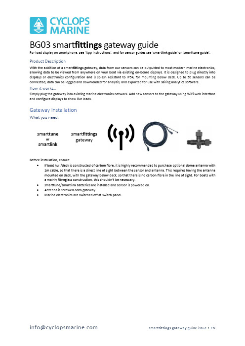
BG03 smart fittings gateway guideFor load display on smartphone , see ‘App Instructions’, and for sensor guides see ‘smart link guide’ or ‘smart tune guide’.Product DescriptionWith the addition of a smart fittings gateway, data from our sensors can be outputted to most modern marine electronics, allowing data to be viewed from anywhere on your boat via existing on-board displays. It is designed to plug directly into displays or electronics configuration and is splash resistant to IP54, for mounting below deck. Up to 50 sensors can be connected, data can be logged and downloaded for analysis, and exported for use with sailing analytics software.How it works…Simply plug the gateway into existing marine electronics network. Add new sensors to the gateway using WiFi web interface and configure displays to show live loads.Gateway InstallationWhat you need:smart tuneorsmart linksmart fittings gatewayBefore installation, ensure:• If boat hull/deck is constructed of carbon fibre, it is highly recommended to purchase optional dome antenna with1m cable, so that there is a direct line of sight between the sensor and antenna. This requires having the antenna mounted on deck, with the gateway below deck, so that there is no carbon fibre in the line of sight. For boats with a mainly fibreglass construction, this shouldn’t be necessary.• smart tune /smart link batteries are installed and sensor is powered on. • Antenna is screwed onto gateway.• Marine electronics are switched off at switch panel.NMEA2000 electronics1.Find NMEA2000 CANbus/backbone closest to load sensors. For example, for a forestay smart tune, the backbone closestto the forward bulkhead is optimal. It is important to find the right location to allow for the strongest, uninterrupted signal from the sensors. If necessary, a NMEA2000 drop cable can be added in to reach this position (not supplied).Typical locations for backbones include:a.Behind displaysb.Mast basec.Near speed & depth sensors2.Connect supplied T-connector + drop cable to gateway M12 connector (larger of the two) and backbone.3.Power on marine electronics.NMEA0183 electronics (includes NKE products)1.Find nearest installed marine electronics device to wireless load sensors with NMEA0183 input. Consult manufacturerdocumentation for more information.2.Connected supplied cable to gateway M8 Connector (smaller of two) and to NMEA0183 input using below wiringarrangement:3.Power on marine electronics.Gateway Web InterfaceThe web interface can be used to view live load data, add, modify or remove sensors, download log files and change general settings. Viewing the web interface requires connection to gateway WiFi, or to an existing WiFi network that the gateway has been programmed to connect to.Connect to Gateway WiFi Network1. After installation, ensure marine electronics (including gateway) are powered on.2. Using smartphone/tablet/laptop, connect to gateway WiFi, as shown on label (left).IMPORTANT: While connected to Gateway Wi-Fi, the below message (or similar) may appear. Always select ‘Keep tryingWi-Fi’, otherwise connection to web interface will not work.Access web interfaceThe web interface can be accessed using a web browser such as Chrome or Safari, at 192.168.4.1PLEASE NOTE: Your retailer may have pre-configured your gateway to listen for your load sensor.Serial num ber: BG03-12345 W iFi Net w ork: cyclop s12345W iFi Passw ord:sadgnlnr W eb in t erface URL: 192.168.4.1NMEA2000 COM PATIBLESMART FITTINGS GATEW AYc y c l o p s m a r i n e .c o mSensors page explainedS e n s o r l i s t S e l e c t ’N e w S e n s o r ’ t o a d d a s e n s o rE n t e r d a t a k e y p r o v i d e d w i t h s e n s o r h e r e‘U n i t s ’ c h a n g e s w h a t u n i t s t h e l o a d i s o u t p u t t o t h e d i s p l a y s i n .‘P r e c i s i o n ’ c h a n g e s t h e n u m b e r o f s i g n i f i c a n t f i g u r e s t h e l o a d i s s h o w n i n .e .g . ‘0.00X ’ c o u n t s i n m u l t i p l e s of 0.001C h a n g e d e s i g n a t i o n o f s e n s o r f o r B &G a n d S a i l m o n , e .g . F o r e s t a y , B a c k s t a y e t c (l i s t o f 64 n a m e s )S e l e c t f r o m 8 G a r m i n c h a n n e l s . S e n s o r n a m e (a b o v e ) w i l l s h o w o n d i s p l a y (f i r s t 10 c h a r a c t e r s o n l y )I f u s i n g N M E A 0183 o u t p u t , c h o o s e t y p e o f o u t p u t m e s s a g e .O n l y c h a n g e t h i s i f u s i n g w i r e d l o a d s e n s o r c o n n e c t e d t o g a t e w a yD o n ’t f o r g e t t o s e l e c t ‘A d d ’/’C h a n g e ’ w h e n f i n i s h e d !Sensors page – Configuring for NMEA0183NKE electronicsIf NKE is selected as the message type, a drop-down menu will show to choose a dynamic channel. Each sensor will require its own channel. The name displayed will be the first 10 characters of the sensor name.PLEASE NOTE: This functionality has only been verified using the NKE Multigraphic display. Consult your local marine electrician for assistance if unsure.Standard NMEA0183 (extra for experts only)If standard NMEA0183 is selected, it is possible to send a message with the load data mimicking a varie ty of different ‘talkers’ (device types) and as using the format of different variables i.e. Air Temperature, Transducer. Only one sensor can be broadcast via standard NMEA0183. Consult your local marine electrician for assistance in setting this up with your instruments.All sensors added on the ‘Sensors’ page will appear here. If a sensor is not powered on or in range, the last detected load value will show in grey.Log Page explainedN a m e o f s e l e c t e d l o g f i l e –a n e w f i l e i s c r e a t e d e a c h t i m e g a t e w a y i s p o w e r e d o nA p r e v i e w o f t h e t i m e s t a m p e d d a t a w i l l a p p e a r h e r e .T h e s i z e o f t h e f i l e w i l l a p p e a r h e r e .Alters function of M8 connector –can also output for legacyNMEA2000 converter lead, and function as wired sensor inputNMEA0183 speedSelect visible WiFi network from list or enter name here to connectEnter WiFi network password hereNOTE: once the gateway is connected to a WiFi network,its own network will be disabled.Reset the gateway internal clock here (battery powered)Reset the gateway to Factory Settings (all configurations and data will be lost)SafetyPlease read all instructions before installing smart fittings gateway. Consult a professional before undertaking installation if at all unsure.Technical DataWireless 2.4 GHz and 5.0 GHz IEEE 802.11ac wireless, Bluetooth 5.0, BLEDimensions 114 x 63 x 28mmMass 118gHousing Material Flame Retardant ABS (Black) IP54 ratedClock Battery life 10 years。
SenseCAP M2 Multi 平台网关与 SenseCAP 传感器快速入门指南说明书

Quick Start for SenseCAP M2Multi Platform Gateway&SenseCAP SensorsThis tutorial will guide you to connect the SenseCAP LoRaWAN®Sensors to SenseCAP M2Multi Platform Gateways.T ableofContents1.Gateway Network Configuration (1)1.1Connect to Ethernet Cable (1)1.2Connect to WIFI via Luci (2)1.3Connect with Cellular(for4G version) (7)1.4POE connection (8)1.5Checking the Gateway Connection Status (9)2.Bind the gateway (10)3.Connect the SenseCAP Sensors (12)4.SenseCAP Portal and Mate APP (14)4.1Gateway Info (14)4.2Sensor data (15)1.Gateway Network ConfigurationConnect the antenna and power adaptor to the gateway.The power LED will show in red,and in about15s,the indicator on the top will flash green,indicating that the gateway is booting.There are two ways to connect to the Internet.Choose the one that works for you.1.1Connect to Ethernet CableConnect the Ethernet cable to the Ethernet port,and the indicator on the top will show solid green if the gateway is successfully connected to the internet.1.2Connect to WIFI via LuciThere are two ways for users to login Luci configuration page.1.2.1Access via router●Step1:Connect your device to a Ethernet cable,and connect your PC tothe same router.Note:Your PC and device should be connected to the samerouter/network.●Step2:Get IP Address of your deviceCheck the IP Address of your device on your router admin page.●Step3:Get your device Username and PasswordYou can find the Username and Password on your device label.●Step4:Login LuciInput the IP Address of your device in a browser to enter the Luci page. Then input your device username and password to login.1.2.2Access via device AP hotspot●Step1:Turn on the device AP hotspot.Press the button for5s until the blue indicator flashes slowly toenter the configuration mode.●Step2:Connect to the AP hotspot.AP hotspot name is SenseCAP_XXXXXX(6-figure MAC address),default password is12345678;connect your computer to this AP hotspot.●Step3:Get your device Username and PasswordYou can find the Username and Password on your device label.●Step4:Log in to the Local ConsoleInput the IP Address(192.168.168.1)in your browser to enter the Local Console.Then input your device username and password,and click the Login button.1.2.3Connect to a WIFIClick on Network-WirelessClick on the Scan button to scan the WIFI.Select your WI-FI to join the network.Submit the Wi-Fi password,and then click Submit and Save.Then click Save and Apply to apply your settings.The indicator on the top will show solid green if the gateway is successfully connected to the WIFI.1.3Connect with Cellular(for4G version)●Step1:Plug your SIM card into the Nano-SIM card slot●Step2:Login the Luci page,and click on Network-Cellular●Step3:Setup the APN info,and click Save and Apply to apply yoursettings.1.4POE connectionSenseCAP M2supports PoE(Power on Ethernet)and is compatiblewith IEEE802.3af standard.Note:You will need to have an extra PoE switch that provides40V-57V DC power as a PSE(Power Sourcing Equipment)if your modem/router does not support PoE.1.5Checking the Gateway Connection StatusAfter powering on the gateway,there are two ways for you to check the gateway working status::1)LED IndicatorMode DescriptionGreenSolid Gateway is healthy and the internet is well connected. Slow blinking Gateway is booting,please wait.BlueSolidThe gateway is ready for internet connection.Further configuration is needed.Slow blinking Configuration mode,and will auto exit after5mins if no activity.Fast blinking Press the button for30s until the indicator show fast flash will trigger the factory reset.Orange Slow blinkingFirmware is updating,and please do not power off thegateway or disconnect the internet.White SolidGateway is only with a factory firmware,and will be updatedto the latest firmware automatically when it is connected tothe internet.RedSolid Hardware issue or internet connection failure. Slow blinking Gateway not connected to the LNS.2)SenseCAP Mate APPIn the SenseCAP Mate App,“Online status”indicates“Online”when the gateway is connected to the network and can receive and transfer sensor data.Please refer to the next chapter for obtaining the SenseCAP App.2.Bind the gatewaySenseCAP Mate APP supports device configuration and remote management.●Step1:Download the SenseCAP Mate APPSenseCAP Mate APP for iOS on App StoreSenseCAP Mate APP for Android on the Google Play StoreYou can also download App from App Center●Step2:Login the APPIf it is your first time to use the SenseCAP platform,please register an account first.Note:Please select Global of Server Location.Step3:Add deviceClick the+in the upper right corner and select Add deviceThen scan the QR code on your gateway label.Set up your device name and location.Then confirm your settings.After successful binding,you will see your gateway in the Device directory.3.Connect the SenseCAP SensorsStep1:Add deviceClick the+in the upper right corner and select Add device Then scan the QR code on your gateway label.Step2:Select the frequency planClick on"Settings",set the platform and frequency,the frequency should match your gateway frequency.eg:If your gateway is US915version,then you need to set your sensor to US915frequency.Note:SenseCAP M2Multi-Platform Gateway can’t connect to Helium network.For more configurations about SenseCAP sensors,please refer to: SenseCAP Sensors4.SenseCAP Portal and Mate APPSenseCAP Mate APP and SenseCAP Portal can be used to check your device status and device management.●SenseCAP Mate APP for iOS on App Store●SenseCAP Mate APP for Android on the Google Play Store●SenseCAP Portal4.1Gateway InfoCheck the gateway info on the SenseCAP Portal and SenseCAP Mate APP SenseCAP Portal SenseCAP Mate APP4.2Sensor dataCheck the sensor data on the SenseCAP Portal and SenseCAP Mate APP SenseCAP Portal SenseCAP Mate APP。
TSIM-01KNXIP路由器V1.00技术说明书V0.10110719
TSIM-01KNX/IP路由器 V1.00 技术说明书(版权所有,翻版必究)评审记录变更日志目录1.引言 (1)1.1.目的 (1)1.2.背景 (1)2.外形与接线图 (2)2.1.外形结构 (2)2.2.接线图 (2)2.3.注意事项 (3)3.技术参数 (4)3.1.额定参数 (4)3.2.技术指标 (4)3.2.1.具体指标 (4)3.2.2.机械性能 (5)3.2.3.电磁兼容 (5)4.硬件介绍 (6)4.1.硬件结构 (6)5.功能说明 (7)5.1.耦合器功能(KNX NET/IP路由) (7)5.2.总线访问功能(KNX NET/IP隧道) (10)6.参数与设置 (11)6.1.ETS数据库 (11)6.1.1.General参数 (11)6.1.2.IP configuration参数 (12)6.1.3.Routing (KNX -> IP)参数 (14)6.1.4.Routing (IP -> KNX)参数 (15)6.2.ETS连接管理 (16)1.引言1.1.目的本文档是对TSIM-01 KNX/IP路由器V1.00的技术说明书,描述了KNX/IP路由器的功能及技术参数。
本文档面向的读者是开关驱动器模块的开发人员及工程部相关人员。
1.2.背景项目名称:TSIM-01 KNX/IP路由器根据TSIM-01 KNX/IP路由器的开发需求,主要完成功能为KNX/IP核心服务、设备管理、隧道、路由和PoE等功能。
2.外形与接线图2.1.外形结构图2-1 KNX/IP路由器外形结构图2.2.接线图图2-2 KNX/IP路由器接线图1: 外部电源端子(12 V ~24 VAC/DC)2: KNX/EIB总线端子3: 学习按钮4: 学习LED指示灯(红色)5: LED指示灯(绿色):-点亮表示KNX/EIB总线有电-闪烁表示KNX/EIB总线数据传输6: LED指示灯(绿色):- 点亮表示以太网已连接- 闪烁表示以太网数据传输7: RJ45以太网接口2.3.注意事项TSIM-01(750)KNX/IP路由器可用于作为KNX/EIB的接口,KNX/EIB可以通过局域网中的任何一点进行访问。
迈思德OPC网关功能简介
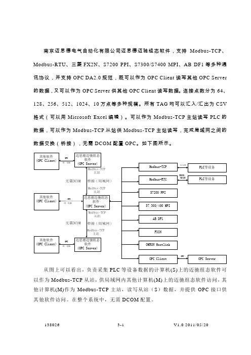
南京迈思德电气自动化有限公司迈思德迈驰组态软件,支持Modbus-TCP、Modbus-RTU、三菱FX2N、S7200 PPI、S7300/S7400 MPI、AB DF1等多种通讯协议,并支持OPC DA2.0规范,既可以作为OPC Client 读写其他OPC Server 的数据,又可以作为OPC Server供其他OPC Client读写数据。
连接点数分为64、128、256、512、1024、10万点等多种规模。
所有TAG均可以汇入/汇出为CSV 格式(可以用Microsoft Excel编辑)。
可以作为Modbus-TCP主站读写PLC的数据,可以作为Modbus-TCP从站供Modbus-TCP主站读写,完成局域网之间的数据交换(桥接),无需DCOM配置OPC。
如下图所示。
从图上可以看出,负责采集PLC等设备数据的计算机(S)上的迈驰组态软件可以作为Modbus-TCP从站,供局域网内其他计算机(M)上的迈驰组态软件访问,其他计算机(M)作为Modbus-TCP主站,读写从站(S)数据,并提供OPC接口供其他软件访问。
在整个系统中,无需DCOM配置。
138026 3-1 V1.0 2011/05/20。
- 1、下载文档前请自行甄别文档内容的完整性,平台不提供额外的编辑、内容补充、找答案等附加服务。
- 2、"仅部分预览"的文档,不可在线预览部分如存在完整性等问题,可反馈申请退款(可完整预览的文档不适用该条件!)。
- 3、如文档侵犯您的权益,请联系客服反馈,我们会尽快为您处理(人工客服工作时间:9:00-18:30)。
家庭智能网关—产品功能演示
Smart home solution
观看网络电视
智能家电监控
安全 便捷 游戏、应用中心 稳定 远程视频监控
社区信息发布
周边商城查看
远程报警监控
Smart home solution
观看网络电视
设备:电视机、智能网关、PAD(遥控 器) 功能:您可以通过PAD、遥控器等观看 激动人心的电视节目,或者点播您喜欢 的电视剧或者球赛,您也可以摆脱线路 的限制,可以自由自在的,随时随地的 上网浏览或者观看电视电影节目。
周边商城查看
设备:摄像头、智能网关、终端(pad、 PC机、手机) 功能:可以将各个商家如超市、酒楼、 诊所等编辑好的信息放在小区中心服务 器上,建立虚拟超市,小区业主通过智 能网关就可以登录中心服务器实时浏览 各类信息。
超市、酒楼、诊所等信息
社区信息
家庭智能网关
PCΒιβλιοθήκη PAD终端查看手机
PAD PC
管理中心
AP
PAD 英特网 局域网 家庭智能网关 安防设备
手机
Smart home solution
社区信息发布
设备:PAD/PC、智能网关 功能:物业管理者可以编辑如文字、图 片、视频等各种信息,实时的将信息发 送至业主家中的智能网关上,业主可以 通过智能网关提示来浏览中心服务器上 的各类信息。
游戏、应用中心
设备:智能网关、终端(pad、PC机、 手机) 功能:您可以通过pad、PC机、手机等 进行高速上网查看应用商城,并下载您 感兴趣的应用软件。
Smart home solution
智能家电控制
设备:PAD(PC、手机、遥控器)、智能网关、 智能家电 功能:您可以通过移动终端(pad、pc、手机) 或者于本地通过遥控器,实现对智能家电的监 控,比如远程开启空调、热水器、电饭煲、远 程关闭电视、电灯等。
远程视频监控
设备:摄像头、智能网关、终端(pad、 PC机、手机) 功能:您可以应用pad、PC、手机等,登 陆应用软件,查控摄像头。实现对家庭环 境的实时监控
PC
PAD 手机
PC
PAD 手机
Smart home solution
远程报警监控
设备:PAD(PC、手机、遥控器)、智能网关、 安防设备 功能:您可以通过移动终端(pad、pc、手机) 或者于本地通过遥控器,实现对家庭安防设 备的监控,包括查看报警信息、布撤防等