楼宇自控REGIN TT-S1电加热备用板
(完整版)楼宇自控系统技术规范书

楼宇自控系统技术规范书编制:校核:审核:批准:单位:北京******设计有限公司日期:2013.5. 26目录附件1 技术规范 (1)1总则 (1)2工程概况 (1)3技术要求 (2)3.4 能源监测系统技术要求 (12)3.5供货范围 (15)3.6 智能照明系统说明 (15)3.6.1 总则 (15)3.6.2 区域控制 (15)3.7 供货范围 (16)3.7.1本系统主要设备须包括﹐但不限于下列项目﹕ (16)3.7.2 硬件要求 (17)3.7.3 软件要求 (17)附件2 供货范围 (18)1一般要求 (18)2供应范围 (18)附件3技术资料和交付进度 (19)1一般要求 (19)2资料提交的基本要求 (20)3文件和资料发送单位和地址 (20)附件4 交货进度 (18)附件5 监造、检验和性能验收试验 (19)附件6 技术服务和设计联络 (24)附件7 分包与外购 (26)附件8 大(部)件情况 (26)附件9 技术差异表 (26)附件10 投标人需要说明的其它问题 (23)附件11 推荐技术方案(如果有) (26)附件12 投标文件附表或附图 (26)附件13 分项价格表 (26)附件14 履约保函(由商务附加统一格式) (26)附件1 技术规范1总则1.1本技术规范书适用于*********有限公司1号楼加建工程楼宇自控系统及其附属设备的功能设计、结构、性能、安装和试验等方面的技术要求。
1.2本技术规范书所提出的是最低限度的技术要求,并未对一切技术细节作出规定,也未充分引述有关标准和规范的条文。
投标方应保证提供符合本规范和现行工业标准的优质产品。
1.3在签订合同之后,到投标方开始制造之日的这段时间内,招标方有权提出因规范标准和规程发生变化而产生的一些补充修改要求,投标方应遵守这个要求,具体款项内容由供、需双方共同商定。
1.4本规范所使用的标准,如遇与投标方所执行的标准不一致时,按较高的标准执行。
热控专业设备材料清册

套
1
包括各种类型的模件、机架、导线、安装附件及软件等
四
主要仪表
1
风量,流量测量装置
套
6
2
热电阻
支
60
3
热电偶
支
50
4
双金属温度计
个
30
5
压力,差压变送器
台
90
6
压力,差压开关
个
20
7
压力表
块
60
8
电动执行机构
台
8
五
电缆及安装材料
1
电缆桥架
吨
8
2
钢材
吨
1
序号
名称
规范
单位
数量
面
2
包括各种类型的模件、机架、导线、安装附件及软件等
2
DCS电源柜
面
1
3
操作员站
套
6
包括系统及应用软件和必要的硬件。
4DEBiblioteka 操作站套1包括系统及应用软件和必要的硬件,随汽机供货。
序号
名称
规范
单位
数量
生产厂家
备注
5
工程师站
套
1
包括系统及应用软件和必要的硬件。
6
打印机
台
2
三
PLC系统
1
化学补给水程控及就地控制仪表和设备
设
序号
名称
型号及规范
单位
数量
生产厂家
备注
一
控制盘、台、柜、箱
1
热控仪表电源柜
面
1
2
汽机TSI机柜
面
1
LTUM1 Series 振子漏电开关说明书

Tuning Fork Level SwitchContents1.Models (4)2.Wiring (5)3.Fork Sensing Spot (6)4.Magnetic Test (6)5.Output Status (7)6.Installation (8)7.Simple Troubleshooting (9)1. Models2. WiringPower supply is DC. Output is PNP / NPN. Please see Figure 1.PNP wiring:●High (Max.) Mode: No. 1 pin (Brown) is connected to L-. No.3 pin (Blue) isconnected to L+. Output is connected to No. 2 pin (Black) , then connectedto L-. No. 4 pin (Yellow Green) goes to ground.●Low (Min.) Mode: number 1 pin (Brown) is connected to L-. No.2 pin(Black) is connected to L+.●Output is connected to No. 3 pin (Blue), then connected to L-. No. 4 pin(Yellow Green) goes to ground.PNP wiring:●High (Max.) Mode: No. 1 pin (Brown) is connected to L+. No.3 pin (Blue) isconnected to L-. Output is connected to No. 2 pin (Black) , then connectedto L+. No. 4 pin (Yellow Green) goes to ground.●Low (Min.) Mode: No. 1 pin (Brown) is connected to L+. No.2 pin (Black) isconnected to L-. Output is connected to No. 3 pin (Blue) , then connected toL+. No. 4 pin (Yellow Green) goes to ground.3. Fork Sensing SpotLTUM1 fork sensing spot is shown as Figure 3 below. Considering testingmedium is water (S.G.=1 g/cm3) , sensing spot is at the fillister about 23mmfrom the tip. If testing medium has S.G. lower than 1g/cm3, sensing spot would be above the fillister. In contrast, sensing spot will be below the fillister.4. Magnetic TestAfter the switch is installed and powered, magnetic test function can beperformed accordingly. The testing point is marked on the housing label. User holds the magnet and moves it close to testing point, the output status will switch from NO. to NC. or NC to NO. and red LED would switch ON or OFF while fork continues to vibrate. When magnet is pulled away from the testing point, theoutput status and red LED would return as default while fork continues to vibrate.The purpose of testing is to confirm the wiring and functioning are correct.5. Output StatusLTUM1 is equipped with two wires power supply. Relay output is connected in two wiring power (L+/–) , which offers Min./ Max. modes according to different pin numbers. When powered with 20 to 250、50/60 Hz Vac / Vdc, top of housing would light up with blue LED.●Low (Min.) Mode: Tuning fork switch will be actuated 3 seconds after thepower is on. Relay is NO and red LED indication is off.When tuning fork is covered by testing medium, vibration stops and relaybecomes NC. Red LED indication is on.●High (Max.) Mode: Tuning fork switch will be actuated 3 seconds after thepower is on. Relay is NC and red LED indication is on. When tuning fork iscovered by testing medium, vibration stops and relay becomes numbeRRed LED indication is on.●Flashing red indicates abnormal: Possible causes overloads or short-circuitload back, equipment malfunction or wear tuning fork probe.6. InstallationHorizontal Installation:1. Can be applied in viscosity, powder and, liquid. Do not inst.(Figure 1)2. When installing the product, The position hole plug must be upwarddirection.If not, incorrect installation could be damage the product.(Figure 2)(Figure 1) (Figure 2)Vertical Installation:1. Opening of the two fork blades is to be as the flow direction. (Figure 3)2. Do not install near substance inlet. (Figure 4)(Figure 3)(Figure 4)7. Simple Troubleshooting11 M5733/0119。
Eaton Pow-R-Line Xpert瞬时开关板产品概述说明书

Low-voltage power distribution and control systems > Switchboards > Pow-R-Line Xpert instant switchboard ContentsGeneral Description . . . . . . . . . . . . . . . . . . . . . . . . . . . 21 .8-2Product Overview . . . . . . . . . . . . . . . . . . . . . . . . . . . 21 .8-2Devices . . . . . . . . . . . . . . . . . . . . . . . . . . . . . . . . . . . . . 21 .8-4Circuit Breakers and Fusible Switches . . . . . . . . . . . . 21 .8-4Product OverviewEaton’s Instant Switchboards are designed as distributor-stocked unitsto provide fast delivery to match the needs of the construction market. Suitable for use as service entrance equipment, they combine utility metering provisions with a fused main switch ina single compact section that can also include a distribution panel for feeder and branch circuit breakers.Typical applications for these versatile switchboards include small office buildings and factories, stores, supermarkets and shopping centers.ConstructionThese switchboards are available in either indoor or outdoor enclosures manufac-tured of code gauge steel with a durable light gray finish. All units are completely enclosed with front, rear and side covers. Outdoor units include a front hinged door. The service section includes:■Main lugs mounted at the top(two #4–600 kcmil per phase)for overhead feed or for use with underground pull section■ A metering and CT compartment with bussing for utility bar type CTs and two 15.00-inch (381.0 mm) high meter compartment doors—one with meter socket provision, one blank■ A 400 or 600 A T-fused main switch or 800 A main circuit breaker with either load lugs (same as main lugs) or with connections to a factory-installed distribution panelUnderground pull sections are avail a ble with lug landing kits, providing studs for incoming cables per EUSERC requirements and two #4–600 kcmil lugs per phase for cable connection to the service section. Distribution panels can be included for 240 Vac maximum (single-phase, three-wire, or three-phase, four-wire) or for480Y/277 Vac (three-phase, four-wire). The 240 V panels have provisions for four two-pole or three-pole, 225 A frame circuit breakers; and 24 poles of 100 A frame circuit breakers. T he 480Y/277 V panel has provisions for four two-pole or three-pole 225 A frame circuit breakers; and 24 poles of 100 A frame circuit breakers. Distribution panel for 800 A 240 Vac or 480Y/277 Vac can be included with provisions for six two- or three-pole, 225 A frame circuit breakers.For applications that require the load circuit conductors to exit at the top, a loadside wireway compartment is available that bolts to the service section.StandardsInstant Switchboards are UL 891 listedand comply with all applicable industrystandards. T hese switchboards meetEUSERC requirements.Service Ratings■240 Vac, single-phase, three-wire,or three-phase, four-wire■480Y/277 Vac, three-phase, four-wireInterrupting Ratings (Series Rating)■65,000 rms symmetrical amperes at240 Vac, with 400 and 600 A fusibleswitch mains using 65,000 AIC ED225 A frame or 10,000 AIC BAB 100 Aframe branch breakers■65,000 rms symmetrical amperes at480Y/277 Vac, with 400 and 600 Afusible switch mains using 35,000 AICFD 225 A frame or 14,000 AIC GHB100 A frame branch breakers■35,000 rms symmetrical at 480Y/277 Vacfully rated using 800 A main circuitbreaker with PDG2xG 225 A framebranch breakersDimensions■Indoor: 32.00 x 90.00 x 14.00 inches(812.8 x 2286.0 x 355.6 mm)■Outdoor: 38.00 x 90.00 x 26.00 inches(965.2 x 2286.0 x660.4 mm)Single-phase, 3 W400600MSB423MSB623RMSB423RMSB623Three-phase, 4 W400600MSB424MSB624RMSB424RMSB624240 V ac Maximum—Main Fused Switch with Distribution PanelSingle-phase, 3 W400600MSBP423MSBP623RMSBP423RMSBP623Three-phase, 4 W400600MSBP424MSBP624RMSBP424RMSBP624240 V ac Maximum—Main Circuit Breaker OnlyThree-phase, 4 W800MSB824RMSB824240 V ac Maximum—Main Circuit Breaker Only with Distribution PanelThree-phase, 4 W800MSBP824RMSBP824480Y/277 V ac a—Main Fused Switch OnlyThree-phase, 4 W400600MSB444MSB644RMSB444RMSB644480Y/277 V ac a—Main Fused Switch with Distribution PanelThree-phase, 4 W400600MSBP444MSBP644RMSBP444RMSBP644480Y/277 V ac Maximum a—Main Circuit Breaker OnlyThree-phase, 4 W800MSB844RMSB844480Y/277 V ac Maximum a—Main Circuit Breaker Only with Distribution PanelThree-phase, 4 W800MSBP844RMSBP844a Not for use on 480 V three-phase three-wire delta systems.Note: Standard switchboards include two 15.00-inch (381.0) high meter compartment doors: one with single meter socket provision and one blank. For other arrangements, use accessories.T ype 1 Indoor Type 3R OutdoorTable 21.8-2. Meter Compartment Doors (Meter Sockets Not Included)Door Size Inches (mm)Drilling CatalogNumber15.00 H x 32.00 W (381.0 x 812.2)Blank1 socketMD150MD15130.00 H x 32.00 W (762.0 x 812.2)Blank2 socketMD300MD302Table 21.8-3. Meter Sockets—For Field Installation (order separately)Number of Jaws Catalog Number4 5 6M4 M5 M68 13 15M8 M13 M15Table 21.8-4. Loadside Wireway—Same Depth as SwitchboardS ection W idth Inches (mm)Catalog NumberNEMA 1—IndoorNEMA 3R—Outdoor12.00 (304.8)LSS12W RLSS12W Table 21.8-5. Underground Pull SectionsS ection W idthInches (mm)Catalog NumberNEMA 1—IndoorNEMA 3R—Outdoor24.00 (609.6)30.00 (762.0)UG24WUG30WRUG24WRUG30WNote: Same depth as switchboard with provisions for lug landing kit. Note: If pull section is to be installed separate from service section, add side closer plates. Cat No. UGCP.400Single-phase, 3WThree-phase, 4WLL4003LL4004800Single-phase, 3WThree-phase, 4WLL8003LL8004Circuit Breaker and Fusible SwitchesPDD2xF PDD2xG PDD2xM PDD2xP 100–225100–225100–225100–2252, 32, 32, 32, 3240240240240125125125125N.I.T.N.I.T.N.I.T.N.I.T.————————2265100200————————————10101010————————————PDG2xF PDG2xF HFDDC c 15–10015–10015–15012, 32, 3277480—125250600N.I.T.N.I.T.N.I.T.———————18—14———14————10—42—1042—————35PDG2xG PDG2xG PDG2xG PDG2xM PDG2xM 15–22515–22515–22515–22515–22512, 3412, 3277600600277600125250250125250N.I.T.N.I.T.N.I.T.N.I.T.N.I.T.———————————6565—10035——65——3535—65—1818—2510——10——1010—22——————————PDG2xM PDG2xP PDG2xP 15–22515–22515–22542, 34600600600250250250N.I.T.N.I.T.N.I.T.——————100200200———65100100253535———222222——————HJDDC c 70–2502, 3—600I.T.——————4242—35PDG3xGy PDG3xG* PDF3xG* d PDG3xM* PDF3xM d 250–40070–40070–40070–40070–4002, 32, 332, 33240600600600600250250250250250N.I.T.I.T.I.T.I.T.I.T.——————————656565100100——————35356565—25253535—————1010102222——————————PDD3xP* HKDDC c LHH e NHH 70–400100–400125–400150–3502, 32, 32, 33600—600600250600250—I.T.I.T.I.T.—————————200—100100————100—656550—3535—42——224242——————35——PDG3xG* f 300–6002, 3600250I.T.—— 65— 35251022——PDG3xM* f PDG3xP* ef 300–600250–6002, 32, 3600600250250I.T.I.T.————100200——65100355010—2242————PDG4xG e PDF4xG df PDG4xM e PDF4xM df HMDLDC c 400–800400–800400–800400–800300–8002, 332, 332, 3600600600600—250———600N.I.T.N.I.T.N.I.T.N.I.T.I.T.——————————6565100100——————50506565—25253535—————422222252542——————————PDG5xM PDG5xP 600–1200600–12002, 32, 3600600——N.I.T.N.I.T.————100200——651003550————————NBDC c 700–12002, 3—600I.T.——————4242—50PDG6xP* 1600 PDG6xP* 2000 700–16001000–200033600600——N.I.T.N.I.T.————200200——1001006565————————PDG6xP* 2500 PDG6xP* cg 1000–25001600–200032, 3600——600N.I.T.I.T.————200———100—65——42—65———65a N.I.T. is non-interchangeable trip unit. I.T. is interchangeable trip unit.b T wo-pole circuit breaker, or two poles of three-pole circuit breaker at 250 Vdc.c For use on DC systems only.d 100% rated.e Not available in Pow-R-Line i X switchboards.f Available in bolt-on fixed mount or drawout feeder device.g Individually, vertically mounted.a 5000 A bolted pressure contact switch is not UL listed.Table 21.8-10. Standard Switchboard Terminals Standard Main Breaker,bNote: All terminal sizes are based on wire ampacities correspondingto those shown in NEC T able 310.16 under the 75 °C insulation columns (75 °C wire). T he use of smaller size (in circular mills), regardless of insulation temperature rating is not permitted without voiding UL labels on devices and equipment.Note: For other terminals available on some ratings of molded case circuit breakers and fusible switches, refer to Molded Case Circuit Breakers & Enclosures Design Guides.Cable Ranges for Standard Secondary Device Terminals Wire and cable terminals supplied on switchboard mounted devices for making up incoming or outgoing cable connections are of the mechanical screw clamp pressure type. All standard terminals are suitable for use with either aluminum or copper cable except as noted in the table. Panel mounted devices use the standard terminal provided with that device.30, 60, 100200#14–1/0#4–300 kcmil400250–750 kcmil or(2) 3/0–250 kcmil600(2) #4–600 kcmil or(4) 3/0–250 kcmil800(3) 250–750 kcmil or(6) 3/0–250 kcmil1200(4) 250–750 kcmil or(8) 3/0–250 kcmilTable 21.8-12. Standard Mechanical Incoming Terminal Ranges for Main400600800(2) #2–500 kcmil(2) #2–500 kcmil(3) #2–500 kcmil100012001600(4) #2–500 kcmil(4) #2–500 kcmil(5) #2–500 kcmil200025003000(6) #2–500 kcmil(7) #2–500 kcmil(10) #2–500 kcmilcc Compression terminations will take a range of conductors and include500, 600, 700 and 750 kcmil.Eaton1000 Eaton Boulevard Cleveland, OH 44122 United StatesEaton .com© 2020 EatonAll Rights ReservedPrinted in USAPublication No . DG015008EN / Z23483Eaton is a registered trademark. All other trademarks are property。
瑞晶Regin楼宇自动化BA系统技术方案

瑞晶Regin楼宇自动化BA系统技术方案无锡海岸新城空调智能化系统设计方案深圳市****二○一一年十月目录楼宇自动化系统(BAS)方案 (4)[摘要] (4)一、需求分析 (7)1.1 监控对象分析 (7)1.2 监控目标分析 (7)二、设计依据和标准 (7)三、系统设计 (8)3.1系统选型 (8)3.2系统设计说明 (10)3.2.1 设计重点 (10)3.2.2要紧设备选型 (11)3.2.3系统通讯网络 (12)3.2.4 系统结构 (13)3.3监控功能说明 (17)3.3.1中央站监控功能 (17)3.3.2与其他系统的集成 (17)3.3.3冷热源系统的监控 (18)3.3.4空调、通风系统 (23)3.3.5给排水系统 (24)3.3.6发电机及配电系统 (24)3.4系统设计专门说明 (24)3.4.1 最先进的软件EXO4系统 (24)3.4.2 节能操纵 (25)3.5集成界面以及接口协议要求 (25)四、系统性能及设备介绍 (25)4.1系统性能介绍 (25)4.1.1中央站功能 (25)4.1.2节能成效技术分析 (27)4.1.3节能及能源操纵软件 (28)4.2 DDC功能介绍 (30)4.2.1 EXOflex操纵器(DDC)介绍 (30)4.2.2EXOcompact操纵器(DDC)介绍 (33)4.2.3 DDC软件 (34)4.2.4 现场设备 (37)五、系统调试 (39)5.1系统调试验收步骤 (39)5.1.1现场操纵器检查 (39)5.1.2电源检查 (39)5.1.3线路敷设的检查 (39)5.1.4系统网络 (39)5.1.5中央监控站硬件及其组态 (39)5.1.6系统软件 (40)5.2设备调试 (41)5.2.1BAS系统出厂测试 (41)5.2.2DDC 加电检测 (41)六、设备清单 (45)楼宇自动化系统(BAS)方案[摘要]依照无锡海岸新城相关图纸,本项目由裙楼商业部份和酒店公寓主体组成,是集大型购物中心、SOHO酒店、住宅、幼儿园、绿花广场等于一体的商业综合体,总建筑面积约50万平方米,无锡海岸新城的显现代表着全新的生活方式与消费潮流的开始,它将以雄浑的商业外观、别致的休闲景观、开放的公共空间、清晰的休闲动线成为无锡新城区的备受期待的高端的生活、工作、休闲目的地。
GEFLEX GFX-M1 GFX-S1 GFX-E1 模块化温控区域电源控制器 说明书
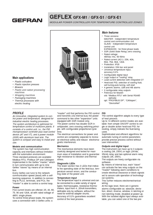
GEFLEX GFX-M1 / GFX-S1 /GFX-E1MODULAR POWER CONTROLLER FOR TEMPERATURE CONTROLLED ZONESMain applications•Plastic extruders•Plastic injection presses •Blowers•Plastic and rubber processing machines•Wrapping machines •Packaging machines •Thermal processes with electric heating Main features•Three versions:MASTER - independent temperature control and communication unitSLAVE - independent temperature control unitEXPANSION - for three-phase loads •SSR (Solid State Relay) zero crossing •Rated voltage:480Vac rms, 50-50Hz•Rated current (AC1): 25A, 40A,60A, 75A, 90A, 120A•Protection: IP20•Installation: DIN bar and panel •Universal temperature input,accuracy 0.2%•Configurable digital input•Logic output or "cooling" relay•Load current detection with integrated CT •Heat/cool PID, selection of cooling fluid, self-tuning,auto-tuning, soft-start• 4 generic alarms, LBA and HB alarms • 2 configurable relay outputs•Field bus for Master:std: “Modbus RTU” with Serial RS485 opticallyopt: “PROFIBUS DP”, “CANopen”,“DeviceNet”PROFILEAn innovative, integrated system to con-trol power and temperature, designed for industrial electric heating processes.The system architecture is optimized for temperature control of multizone plants. It consists of a control unit, i.e., the PID microprocessor controller plus load control device (AT and VT), and a power module (SSR) with aluminum heat sink. The system is compact and easy to install and use.Models and communicationThe system has high communication capacity and interfaces without limitation with the automation environment.Three standard protocols are available: Modbus RTU, Profibus DP and CANopen implemented in the Geflex "master," which in turn communicates with up to nine Geflex "slaves" by means of an internal bus.Every Geflex can tune to the network communication speed (baud) with a self-learning sequence. In addition to connec-ting to PLCs, terminals, and PCs, the "master" is able to control a control loop. PowerFive current levels are offered: 25, 40, 60, 75, 90 and 120A, all with rated voltage of 480V, single phase.To control three-phase loads, the system uses a connection with 3 Geflex units: a "master" unit that performs the PID controland transmits (via internal bus) the powercommand to two other "expansion" unitsequipped with SSR module only.The power control has double SCR inantiparallel, zero crossing switching princi-ple, with configurable proportional cycletime.The electrical connections for power andcontrol are completely separate to increa-se electrical safety and reduce electroma-gnetic interference.MechanicsThe mechanical elements have beencarefully designed and tested for maxi-mum ease of installation and to guaranteehigh resistance to vibration and thermalstress.Diagnostic LEDsThe lower section has 3 LEDs that indica-te the operating state of the field bus, tem-perature sensor errors, and the conduc-ting state of the power unit.Temperature inputThe temperature input is universal and canbe connected to a wide variety of signaltypes: thermocouples, resistance thermo-meters, input from 4...20mA transmitters,definable only by software, without theneed for external adapter shunts.Accuracy of 0.2% guarantees excellentcontrol of the heat process.PIDThe control algorithm adapts to every typeof heat process.Up to 14 different control modes are avai-lable: from simple ON/OFF control to sin-gle or double action heat/cool PID; forcooling, simply indicate the fluid beingused.Sophisticated and efficient algorithms forautomatic tuning of control parametersprovide precise process control withoutuser intervention.Outputs and digital inputThe instrument can have up to 3 outputs:a cooling (3A, 250V) or logic (24Vdc,35mA) relay and two optional alarm relayoutputs (3A, 250V).The outputs are freely configurable viasoftware.By means of internal bus, each "slave"can activate the two relay outputs on the"master" following alarm conditions tocreate electrical clearance or block signalsset to assure safe operation of technologi-cal systems.This further reduces electromechanicalwiring.At the logic level, there are 4 genericalarms configurable as: absolute, devia-tion, direct, reverse, window, in latching ornon-latching mode, disabled at power-up.With the isolated digital input always avai-lable, you can select one of the two pre-POWER MODULEDISSIPATION CURVESCONNECTION EXAMPLESWe advise you to connect a 120Ω1/4W resistance between the "CAN_L" and "CAN_H" signals at both ends of the DeviceNet network.GEFRAN spa reserves the right to make aesthetic or functional changes at any time and without notice.GEFRAN spa via Sebina, 74 - 25050 Provaglio d’Iseo (BS)Tel.03098881 - fax 0309839063Internet: DTS_GFX_0408_ENG。
集肤效应电伴热
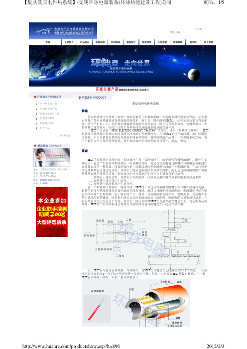
件、旁通、短节和站内短管线等的加热和伴热。对于中、长距离的管线伴热,由于单根伴热电缆
功率较小、电源供电点较多,一旦发生问题,维修较困难,要将所有的保温层去掉才能更换其电
缆。而集肤效应伴热适用于中长距离各种口径管线的伴热,它的优点是:伴热功率大、电源供电
点少,传热效果好,维修方便。因此在各种管线集输中得到了非常广泛的应用。
集肤电伴热系统
单位名称
伴热温 介质 管线长度及电缆用量
度
石油一厂
85℃ 渣油 Ф108mm(8公里集肤电缆)
中油湛江油库
50℃
Ф820mm(3.2公里集肤电缆) 燃料油、
Ф426mm(3.2公里集肤电缆) 重油
Ф426mm(0.8公里集肤电缆)
天津石化公司
80℃ 加氢尾油 Ф273mm(4.7公里集肤电缆)
与其它伴热方法比较
序号 名称特点 集肤效应伴热 电热带伴热 MI电缆伴热
蒸汽伴热
自控温伴热带
1 伴热距离
长
短
短
短(末点温度低)
短
2 电源供电点
少
多
多
多
3 伴热功率
大
小
小
小
4 传热效果
好
一般
一般
一般
一般
5 伴热管敷设 直接焊接
捆扎
捆扎
捆扎
捆扎
6 自动化控制
方便
控制点多 控制点多
无法实现
控制点多
7 维修
4、核电站:重水管线、水管、脉冲线和仪表、储存塔、重水塔。 5、油品交易中转站:产品储存塔、长输管线、低温产品塔基及与塔相关连的管线、水管。 6、电厂:高压给水、排污放空、蒸汽、脱汽、高压冷凝、 酸碱、储重油点火油路等管线; 重油管线、重油塔、脉冲线和仪表、水管、长输管线、水煤浆输送管线等。 7、钢铁厂:生产管线、重油、煤焦油、沥青和硫磺线、水管、长输管线。 8、水泥厂:火炉或窑重油线、水管、脉冲线或仪表、储存塔、重油长输管线。 9、另有塑料加工厂、食用油加工厂、巧克力加工厂、供水厂、宾馆及高层建筑、重型工程工 业。 集肤伴热:可分为管外集肤及管内集肤两种。以上各种类型的管道运输,均可采用集肤效应 伴热。 从实践中得出结论,这种技术方案已取得良好的运输效果和显著的经济效益。
科奥信 XZDW 高频开关壁挂电源小系统 使用说明书

注意事项:1、请不要自行打开机箱,否则我方将不承担保修事宜。
2、本公司制造的智能电力高频开关电源,在额定功率范围内,可以适用于任何使用220V/110V直流电的电器设备。
3、该电源系统在使用过程中有一定的发热量属正常现象、但要保持安装环境的通风散热、干净清洁,特别不能阻塞通风孔。
4、必须按照说明之要求安装使用。
5、请保存好本说明书,作为日后参阅。
目录1.系统功能特点 (1)2.系统技术指标 (1)3.系统型号定义及配置 (2)4.系统电气原理图 (2)5.系统结构及安装 (3)6.PMS-IIIE监控模块 (3)7.KOX220D02整流模块 (8)8.KOX220G02降压单元 (11)9.系统配电及电气安装 (12)10.电池箱结构及安装 (13)概述XZDW系列高频开关电源壁挂小系统是我公司专为小容量系统而设计;适合小型开关站、小型用户变电站、智能大厦配电等场合。
系统由整流模块、监控模块、降压模块、配电单元和电池安装箱构成;具有体积小、结构简单、独立构成系统等特点;监控模块采用LCD汉字菜单显示,系统监控和电池智能化管理功能完善,具有与自动化系统连接的四遥接口,提供RS232和RS485两种通讯选择,提供RTU、CDT、MODBUS 三种通讯规约选择。
1.系统功能特点●适合构成38AH/220V、65AH/110V以下所有系统;●模块、监控单元和降压单元均采用带电热插拔结构,安装、维护方便快捷;●可安装3个2.0A/220V、4A/110V自然冷模块;●降压单元具有自动硅链降压功能,最大电流2A,冲击电流30A/0.5S;●监控器采用LCD显示,汉字菜单,按键操作,可实现系统参数设置、系统工作参数显示、系统故障指示和系统校准;●监控单元具有对电池自动管理的功能;●提供RS232和RS485两种通讯接口选择,提供RTU、CDT、MODBUS三种通讯规约选择,可与电站自动化系统连接;●监控器实现电池电压、控母电压、控母电流、电池充放电电流、模块状态检测;●配电单元提供2路交流输入(可选择一路PT供电)、1路电池输入、3-8路馈电输出;●PT供电时系统自动限制输出功率。
三层某墅电气设计施工图

变电所低压配电系统图

某636㎡二层办公楼电气设计方案施工图

英文软起1拖1两地控.dwg
楼宇自动控制系统技术交底全套

楼宇自动控制系统技术交底全套一、材料设备要求(一)主要设备要求(DDC、前端执行器、控制箱、通讯模块等):1工程所用设备型式、规格、数量、质量在施工前应进行检查,无出厂检验证明材料、与设计不符者不得在工程中使用。
2经检验的设备应做好记录,对不合格的器件应单独存放,以备核查与处理。
3工程中使用的缆线、器材应与订货合同或封存的产品在规格、型号、等级上相符。
4备品、备件及各类资料应齐全。
5各种型材的材质、规格、型号应符合设计文件的规定,表面应光滑、平整,不得变形、断裂。
6管材采用钢管、硬质聚氯乙烯管时,其管身应光滑、无伤痕,管孔无变形,孑宏、壁厚应符合设计要求。
7管道采用水泥管块时,应按通信管道工程施工及验收中相关规定进行检验。
8各种铁件的材质、规格均应符合质量标准,不得有歪斜、扭曲、毛刺、断裂或破损。
9设备的表面处理和镀层应均匀、完整,表面光洁,无脱落、气泡等缺陷。
10各类前端执行器的型号、规格、尺寸等是否符合图纸要求,有无出厂合格证。
11设备在进场前由施工单位或建设单位委托鉴定单位对其各项功能等检测,并出具检测报告。
(二)线缆要求:1工程使用的对绞电缆或专用线缆,其型号、规格应符合设计的规定和合同要求。
2电缆所附标志、标签内容应齐全、清晰。
3电缆外护线套需完整无损,电缆应附有出厂质量检验合格证。
如用户要求,应附有本批量电缆的技术指标。
4设备在进场前由施工单位或建设单位委托鉴定单位对其功率、各项功能等检测,并出具检测报告。
电缆的电气性能抽验应从本批量电缆中的任意三盘中各截出Ic)Om长度,加上工程中所选用的按插件进行抽样测试,并作测试记录。
(≡)UPS:1确定电源的功率、型号、波形是否和图纸、合同要求的相符。
2设备的表面处理和镀层应均匀、完整,表面光洁,无脱落、气泡等缺陷。
3设备在进场前由施工单位或建设单位委托鉴定单位对其功率、电压、电流、波形失真度等各项功能检测,并出具检测报告。
(四)中央管理计算机:1确定是否具有监控、显示、操作、控制、数据管理辅助、安全保障管理、记录、自诊断、内部互通以及其他系统通讯等功能。
- 1、下载文档前请自行甄别文档内容的完整性,平台不提供额外的编辑、内容补充、找答案等附加服务。
- 2、"仅部分预览"的文档,不可在线预览部分如存在完整性等问题,可反馈申请退款(可完整预览的文档不适用该条件!)。
- 3、如文档侵犯您的权益,请联系客服反馈,我们会尽快为您处理(人工客服工作时间:9:00-18:30)。
Easy to install and connect TTC2000 is prepared to plug-in TT-S1. It detects if TT-S1 is installed and automatically adapts the control function accordingly. No adjustments are necessary. Carefully locate the board so that the connectors mate and the TT-S1 legs align with the mounting holes (see picture on the following page). Connect the two terminals to the contactor that controls the basic heating load. TTC2000 and TT-S1 must have separate, equal-sized loads. N.B. The supply should be wired via the fan stat, the high temperature limit switch etc.
Wiring
*
1 2 TT-S1
* = Use for example sensor DTV as fan stat, see data sheet 3-100 for more information.
Installation
:中国广州瑞晶贤力信息科技有限公司 中国分公司: 电话: +86 20 22029181 传真 : +86 20 22029686 手机: +86 13600057088 网址: Q Q Q: 503623494 邮箱: regin168@
Regin product information
revision 09 2005
TT-S1
Ancillary board for TTC2000
Ancillary board intended to control an extra load when using the TTC2000 controller.
• Maximum 25 A load (appr. 17 kW) • Easy installation and start-up
• Potential free relay output • For control of auxiliary contactor
TT-S1 is an ancillary board intended to control an extra load connected to TTC2000. The board controls a contactor which activates or deactivates the heating load. For best function, the load connected to TT-S1 should be of equal size to the load connected to TTC2000 (triac). Function On increasing heat demand, TTC2000 will primarily increase the triac-controlled output. When this reaches 100% the ancillary board will be activated and the triac output will be reduced to 0%. If there is a need for more heating, the triac-controlled output will be in product information
Technical data
Supply voltage Control signal Output Supplied by the connector (TTC2000) Supplied by the connector (TTC2000) Single pole closing relay, 5 A, 230 V AC (terminals 1 and 2) Controls load via contactor. Maximum load via contactor 25 A This product conforms with the requirements of European EMC standards CENELEC EN 61000-6-1 and EN 61000-6-3 and carries the CE mark. This product conforms with the requirements of European LVD standards IEC 669-1 and IEC 669-2-1.