MTL HMI 简介20130801
威纶触摸屏简介
威纶触摸屏简介威纶触摸屏是一种先进的交互式屏幕,可以被用于各种设备上,如智能手机、平板电脑、计算机等。
这种触摸屏使用电容技术实现精准的触控,同时还具有高透明度和耐刮擦的外表设计。
威纶触摸屏的分类威纶触摸屏主要可以分为两种:电容触摸屏和电阻触摸屏。
1. 电容触摸屏电容触摸屏是一种通过电容原理来检测手指移动的触摸屏。
这种触摸屏基于电阻式触摸屏的工作原理,但它可以使用不同的方法来检测触摸。
基于这种原理,电容触摸屏可以更快地响应,因此更为普及。
2. 电阻触摸屏电阻触摸屏是一种使用电阻原理来检测手指移动的触摸屏。
这种触摸屏能够检测到触摸的位置,但由于其含有许多层,因此较为厚重。
威纶触摸屏的优点与传统的机械式按键相比,威纶触摸屏有以下优点:1. 灵敏度高威纶触摸屏可以随着手指的移动而准确地检测到触摸位置。
因此,用户可以更方便地浏览和操作屏幕上的内容。
2. 设计多样性威纶触摸屏具有高透明度和耐刮擦的外表设计,可以配合各种设备的不同形状和大小进行设计。
这种设计多样性使得触摸屏可以更加适应不同的应用场景。
3. 显示效果高威纶触摸屏可以呈现均匀、清晰和高对比度的图像。
因此,威纶触摸屏通常被用于高端设备,如可穿戴设备和智能手机等。
4. 节省空间威纶触摸屏可以替代传统的机械按键,因此可以在不占用额外空间的情况下提供更多功能。
因此,设计师可以更加有效地利用设备的空间。
威纶触摸屏的应用威纶触摸屏可以被用于各种不同的设备上。
以下是一些常见的应用场景:1. 智能手机和平板电脑智能手机和平板电脑通常使用电容式触摸屏,可以通过触摸屏操作来浏览和控制设备。
这种触摸屏使得设备变得更加方便和易用。
2. 可穿戴设备威纶触摸屏可以被用于可穿戴设备,如智能手表、眼镜和耳机等。
这些设备通过触摸屏来实现和用户的交互,方便快捷。
3. 数字签名数字签名系统是一种通过电子方式来签署文件的技术,威纶触摸屏可以被用于数字签名系统中,将签名过程转化为数字化处理,提高效率,降低成本。
市面上常见HMI品牌介绍

一、专业做HMI的品牌:1、Proface(普洛菲斯)普洛菲斯国际贸易(上海)有限公司作为日本迪吉特株式会社(Digital Electronics Corporation)投资的公司,以其创新的科技理念和领先的技术意识为全球客户提供可编程人机界面、工业平板式计算机、图形逻辑控制和工业信息终端等产品,帮助广大用户提高整体生产、经营效率。
Pro-face 这一品牌也在全球范围占主导地位,成为全球HMI行业领袖,在亚洲、美洲、欧洲都占有极高的市场占有率。
自2001年在中国成立公司进入中国市场以来,取得了骄人的业绩,赢得了国内工控领域的良好口碑,现已成为业内主导品牌之一。
Digital在江苏省无锡市设立了工厂,现在Digital已经成为施耐德旗下品牌。
2、HITECH(海泰克)HITECH是台湾的一个品牌,在中国大陆称为海泰克。
它是台湾泉毅电子股份有限公司的品牌,公司成立于1981 年,初期制造用于笔上的电子表。
为了将泉毅转型为以技术导向为主的公司,于1984 年开始研发制造LCD模组。
在当时,泉毅为台湾第一家成功开发LCD模组的厂商。
1990年泉毅成立一个新的R&D部门来积极投入应用于工业自动化领域的人机介面(HMI)研发工作。
泉毅是台湾第一家将嵌入式系统技术结合LCD模组,自行研发出工业级HMI产品的厂商。
经过多年的努力,泉毅已经建立起HMI的自有品牌HMI-Hitech PWS系列,销售据点遍及全世界,包括亚洲、美国及欧洲等。
其已经被瑞典贝尔收购,已经归入贝尔旗下。
其在大陆主要通过天津罗升销售。
目前在国内市场占有率比较高,但已经呈下降趋势。
3、BEIJER(北尔)来自瑞典的BEIJER电子集团,欧洲第一人机品牌,连续3年获得全球工业设计最佳奖IF设计大奖,全系列人机采用铝镁合金外壳设计,纤薄抗干扰能力强,64K TFT真彩显示,画面靓丽清晰,内嵌WinCE操作系统,功能强大,可靠性高,前面板防护等级为IP66,通过UL\DNV\RoHS等多种认证。
HMI人机界面产品培训ppt文档

产
3.HMI概述
品
价
格
4.HMI产品对比
AB Siemens Schneider Mitusibishi Omron Proface
5.HMI特点 6.HMI应用
Hitech Low Winview
Low
产品性能
欧美派 日本派 台湾派
high
HMI产品总览
1.HMI基本原理
施耐德系列
从字符型显示终端到图形终端的全系列产品线
TD400、OP73Micro/K-TP178、OP77A/OP77B TP170B/TP177A、TP270/TP277/MP277、MP370
XBTGT系列、 XBTN/ R系列
MT500系列、MT6000系列、MT8000系列
GOT 900系列、 GOT 1000系列
MPT002、NT11 NT系列、NS系列
4. 上位组态软件,如ProTool, Wincc flexible, Vijeo
6.HMI应用
Designer
工业触摸屏-面板的构成
1.HMI基本原理 电阻触摸板
用于检测用户触摸位置
2.HMI市场概况
液晶显示板
显示CPU发送来的信息
3.HMI概述
控制器
4.HMI产品对比
从触摸点检测装置上接 收触摸信息,并将它转
HMI人机界面产品培训
培训内容
1.HMI基本原理 2.HMI市场概况 3.HMI概述 4.HMI产品对比 5.HMI特点 6.HMI应用
1.HMI基本原理 2.HMI市场概况 3.HMI概述 4.HMI产品对比 5.HMI特点 6.HMI应用
HMI基本原理
1.HMI基本原理 广义的定义:使用者与机器间沟通、传递 及接受信息的接口
新人培训_HMI产品介绍

X品質 低
nTouch
KOYO M2I
2007 Delta
Hitech
2008 Delta
高
eView WeinView
17
低
Xinje
Human Machine Interface
第二部分
第二部分
台达人机界面介绍
series
TP 系列
A 系列 AE 系列
专业触摸屏人机界面
AS 系列
B 系列
市场容量与竞争对手
市场总容量在14亿元左右 主要分布在产业机械、电力、化工、交通等领域 主要竞争对手:E-VIEW、 EasyVIEW WEINVIEW 、 HITECH、Proface……
各品牌位置
Y價格 高
Siemens
Fuji HAKK
O
Proface
Mistubishi
ESA Beij
eRred
精密电阻网络触摸面板无Touch Cell的限制, 触摸精度高,可以自由编制完美的界面
精密电阻网络结构
阵列电阻网络结构
液晶显示面板(LCD Screen)
液晶显示面板(LCD Screen)
常用液晶显示面板有STN和TFT两种 STN(超扭曲阵列)液晶属于被动式 液晶,需要背光灯管,后来又发展出 大尺寸的DSTN(双层超扭曲阵列)液 晶,它成本较低 TFT(薄膜电晶体)液晶属于主动式液 晶,它依靠微小电晶体发光,亮度较 高色彩鲜艳,但成本也较高
塑料机械设备
注塑机 压塑机 取模机械手 自动吹瓶机
其他非标设备
CNC数控弯管机 数控多轴绕线机 轴承生产设备 物流输送设备 自动喷涂烘烤设备 自动印刷设备
触摸屏人机界面的应用
HMI认识
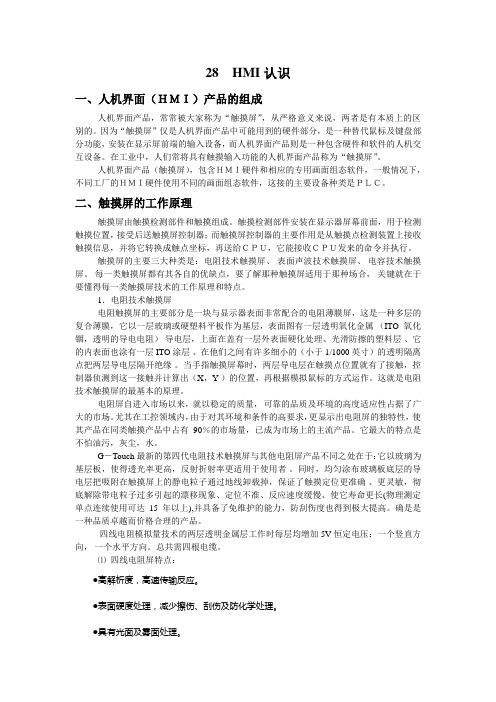
28 HMI认识一、人机界面(HMI)产品的组成人机界面产品,常常被大家称为“触摸屏”,从严格意义来说,两者是有本质上的区别的。
因为“触摸屏”仅是人机界面产品中可能用到的硬件部分,是一种替代鼠标及键盘部分功能,安装在显示屏前端的输入设备,而人机界面产品则是一种包含硬件和软件的人机交互设备。
在工业中,人们常将具有触摸输入功能的人机界面产品称为“触摸屏”。
人机界面产品(触摸屏),包含HMI硬件和相应的专用画面组态软件,一般情况下,不同工厂的HMI硬件使用不同的画面组态软件,这接的主要设备种类是PLC。
二、触摸屏的工作原理触摸屏由触摸检测部件和触摸组成。
触摸检测部件安装在显示器屏幕前面,用于检测触摸位置,接受后送触摸屏控制器;而触摸屏控制器的主要作用是从触摸点检测装置上接收触摸信息,并将它转换成触点坐标,再送给CPU,它能接收CPU发来的命令并执行。
触摸屏的主要三大种类是:电阻技术触摸屏、表面声波技术触摸屏、电容技术触摸屏。
每一类触摸屏都有其各自的优缺点,要了解那种触摸屏适用于那种场合,关键就在于要懂得每一类触摸屏技术的工作原理和特点。
1.电阻技术触摸屏电阻触摸屏的主要部分是一块与显示器表面非常配合的电阻薄膜屏,这是一种多层的复合薄膜,它以一层玻璃或硬塑料平板作为基层,表面图有一层透明氧化金属(ITO氧化铟,透明的导电电阻)导电层,上面在盖有一层外表面硬化处理、光滑防擦的塑料层、它的内表面也涂有一层ITO涂层、在他们之间有许多细小的(小于1/1000英寸)的透明隔离点把两层导电层隔开绝缘。
当手指触摸屏幕时,两层导电层在触摸点位置就有了接触,控制器侦测到这一接触并计算出(X,Y )的位置,再根据模拟鼠标的方式运作。
这就是电阻技术触摸屏的最基本的原理。
电阻屏自进入市场以来,就以稳定的质量,可靠的品质及环境的高度适应性占据了广大的市场。
尤其在工控领域内,由于对其环境和条件的高要求,更显示出电阻屏的独特性,使其产品在同类触摸产品中占有90%的市场量,已成为市场上的主流产品。
西门子HMI介绍 PPT课件

冗余功能:在运行系统中服务器互相监控,达到提早识别故障服务器的目的。 如果一台服务器出了故障,客户机将自动从故障服务器切换到仍在运行的服 务器上。这样保证监控和操作过程中所有客户机可用。出现故障时,激活的 服务器会继续将WinCC项目的所有消息和过程数据归档。故障服务器恢复在 线后,所有消息的内容、过程值以及用户归档将自动复制到恢复的服务器。
此处添加变量
运行情况,用户通过相应操作可以监视现场情 况,并对现场设备进行开启,关闭等操作。
阀开启关闭 罐液位监控
8
2.4 报警处理
组态报警编辑器,可以对现场重要的设备输入点进行监控,如果此数据点 出现异常,则在报警画面上进行显示,便于操作人员快速进行故障排除等, 报警一般分为故障,警告,信息等
内容
1, 基本概念与系统配置 2, WinCC系统 3, Protool系统 4, 演示
1
1, 基本概念与系统配置
HMI(Human Machine Interface-人机接口)是操作人员与底层设备之 间的一种接口,覆盖了特定的生产线区域与相应的设备之间建立连接。 可以实现现场操作,数据存储,状态监视,报警,变量归档,报表打 印等功能。
HMI画面客户机,通过 TCPIP协议与服务器连 接,操作人员可以在此 之上进行操作等,放置 在现场
HMI产品简介

HMI STO/STU 3.4”/3.5”/5.7”
文本屏 (简单应用)
Schneider Electric - Control & Architecture
触摸屏
工控机
4Байду номын сангаас
(复杂
小型文本及半图形终端
小型图形终端
新一代
XBT N/R/RT 适用于小型设备及其简单应用
Vijeo Designer Lite
20 键 (12个键可用户可自定义) 拉丁文 , 中文 , 斯拉夫语, 西腊文, 日文 5 VDC 1 24 VDC 2
Modbus master/UniTE (point to point)
Modb. master-slave Modb. master/UniTE Modb. master/UniTE (point to point) (Multipoint)/UniTE (Multipoint)
Schneider Electric - Control & Architecture
18
Magelis STU 模块化触摸屏结构
USB A型口 支持U盘更新程序 支持扩展连接USB打印机,键盘等设备
触摸前面板 HMISTU主 机面板
USB B型口(Mini USB) 标准Mini USB编程口 与M238/M218共用一根编程电缆
HMI STO/STU
XBT OT/GT/GK/GH XBT GC
Smart/Compact/Flex PC
Schneider Electric - Control & Architecture
14
Magiles STO/STU 产品选型
新人培训-HMI讲解

面包加工配料表
A
B
C
水
2.5L
3L
2.8L
糖
二两 三两 四两
食用油 1L
1.2L
0.8L
面粉
2kg
1.4kg 1.9kg
鸡蛋 10个 13个 15个
回目錄
DOP-B 的功能介绍 配方功能应用场合
A、数据量比较大 B、参数分组,不同的工艺执行不同的参数 C、需要存储
回目錄
DOP-B 的功能介绍
配方如何寻址
回目錄
DOP-B新功能介绍
eServer
eServer是一个PC端软件用于协助客户通过网络收集 HMI或是连接于HMI的PLC(或其他设备)的信息
eServer支持 MicrosoftExcel并支持各 项Excel内置公式及图表, 客户可通过eServer针对不 同的需求快速制作所需要 的报表
寄存器编号
举例 Dn (D0)
配方控制寄存器 RECR
Dn+5 (D5)
配方组别指定寄存器RBIR Dn+6 (D6)
bit
0 1 2 3 4~7 8~15
DECR 功能说明 (Dn+5)
配方组别变更 配方读取(PLC-HMI) 配方写入(HMI-PLC) 配方组合变更 保留 指定要变更配方组合的编号
Hitech
7
Omron
7
Delta
7
Hitech
7
Omron
8
Hitech
8
Hitech
8
Delta
8
Fuji
9
MCGS
9
Schneider
9
Schneider
HMI人机界面的组成及工作原理介绍
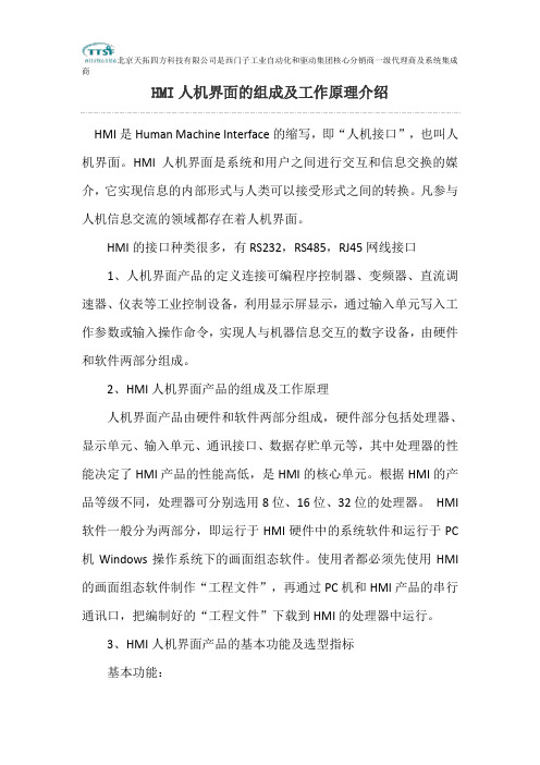
HMI人机界面的组成及工作原理介绍HMI是Human Machine Interface的缩写,即“人机接口”,也叫人机界面。
HMI人机界面是系统和用户之间进行交互和信息交换的媒介,它实现信息的内部形式与人类可以接受形式之间的转换。
凡参与人机信息交流的领域都存在着人机界面。
HMI的接口种类很多,有RS232,RS485,RJ45网线接口1、人机界面产品的定义连接可编程序控制器、变频器、直流调速器、仪表等工业控制设备,利用显示屏显示,通过输入单元写入工作参数或输入操作命令,实现人与机器信息交互的数字设备,由硬件和软件两部分组成。
2、HMI人机界面产品的组成及工作原理人机界面产品由硬件和软件两部分组成,硬件部分包括处理器、显示单元、输入单元、通讯接口、数据存贮单元等,其中处理器的性能决定了HMI产品的性能高低,是HMI的核心单元。
根据HMI的产品等级不同,处理器可分别选用8位、16位、32位的处理器。
HMI 软件一般分为两部分,即运行于HMI硬件中的系统软件和运行于PC 机Windows操作系统下的画面组态软件。
使用者都必须先使用HMI 的画面组态软件制作“工程文件”,再通过PC机和HMI产品的串行通讯口,把编制好的“工程文件”下载到HMI的处理器中运行。
3、HMI人机界面产品的基本功能及选型指标基本功能:1)设备工作状态显示;2)数据、文字输入操作,打印输出;3)生产配方存储,设备生产数据记录;4)简单的逻辑和数值运算;5)可连接多种工业控制设备组网。
选型指标:1)显示屏尺寸及色彩,分辨率;2)HMI的处理器速度性能;3)输入方式:触摸屏或薄膜键盘;4)画面存贮容量,注意厂商标注的容量单位是字节、还是位;5)通讯口种类及数量,是否支持打印功能。
4、HMI人机界面产品分类薄膜键输入的HMI,显示尺寸小于5.7ˊ,画面组态软件免费,属初级产品。
显示屏尺寸为5.7ˊ~12.1ˊ,画面组态软件免费,属中级产品。
MTL防爆触摸屏使用手册
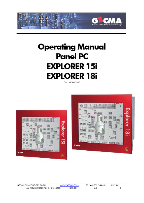
Operating ManualPanel PC EXPLORER 15i EXPLORER 18iDoc: 60000206GECMA COMPONENTES GMBH TEL. +49 2237 6996-0FAX. -99ContentsContents Contents........................................................................................................................................................................................................................................................2 Introduction ..............................................................................................................................................................................................................2 Variants of the Explorer Variants of the Explorer................................................................................................................................................................................................................2 Assembly Assembly......................................................................................................................................................................................................................................................3 Notes Notes................................................................................................................................................................................................................................................................4 Softwareinstallation Softwareinstallation..........................................................................................................................................................................................................................4 Technical Data Technical Data......................................................................................................................................................................................................................................6 Connection details Connection details............................................................................................................................................................................................................................7 Terminal Connections Terminal Connections..............................................................................................................................................................................................................1313 Safety Instructions Safety Instructions............................................................................................................................................................................................................................1717 General Instructions General Instructions.. (18)18IntroductionThe Explorer 15i/18i is a display with an integrated PC for installation in hazardous areas.It is equipped with intrinsically safe communication interfaces for connection of other components such as keyboard, mouse or barcode scanner.Some of the interfaces and the power supply input are increased safety and accessed via an Ex e terminal enclosure.When the Explorer 15i/18i is correctly mounted into a min. IP6X certificated housing (with a cut out of 417mm x 328,5mm resp. 16,43“x12,94“ for Explorer 15i or 476mm x 396mm resp. 18,75"x15,6“ Explorer 18i) installation in a zone 21 is permitted.Variants of the ExplorerThe Explorer is available in two different variants: Explorer 15i Explorer 15i (Display size appr. 15”) Explorer 18i Explorer 18i(Display size appr. 19”)The following options are available: Touch Touch(Touch screen)G -Touch Touch (Glass Touch screen) HB HB (High Brightness) BS BS (Brightness sensor)AC AC (100-240V AC 50/60Hz, max. 120W)DC DC (20-30V DC, max. 120W)5V is5V is (5V is supply, e.g. to supply a BCS)Additionally you can order interface options as below: 1x RS485 or RS422-Interface Ex e (instead the RS232 Ex e interface)AssemblyTo ensure the ingress protection IP66 / NEMA 4X for the Explorer 15i/18i-module it must becorrectly mounted in a min. IP66 / NEMA 4X certificated housing (with a cut out of 417mm x328,5mm resp. 16,43“x12,94“ for Explorer 15i or 476mm x 396mm resp. 18,75"x15,6“ forExplorer 18i).The use of the device in Zone 21 are permitted, when the Explorer 15i/18i correct mounted in a min.IP6X approved housing (with a cut out of 417mm x 328,5mm resp. 16,43“x12,94“ for Explorer 15i or 476mm x 396mm resp. 18,75"x15,6“ for Explorer 18i).The Explorer 15i/18i-module is inserted into the housing cut-out with its front side to the exterior and fastened from the inside via a minimum of 18 mounting clips which are evenly distributed over theexternal circumference (for Explorer 15i) or via a minimum of 24 mounting bolts which are evenlydistributed over the external circumference secured with nuts (for Explorer 18i) in such a way that the module is flush and tight fitting to the housing.The electrical connections can be seen in the wiring diagram #30100358 or #30100399 and the Ex certificate.We recommend to use CAT7 installationcable for the connection of the ethernetinterface X53. Theethernetinterface of the Explorer should be connected to a switch or similar device. Thedatacablepairs should be drilled together and connected as short as possible to the terminals inside the Ex e connectionbox.Follow the safety instructions at all times.When the Device will be mounted to a FHP-Enclosure with coupling (MB) and STF please followlisted instructions:1.Fix the STF pipe stand or EBF elbow stand to the floor or wall. Ensure that the floor or wall isstrong enough to take the load of the FHP enclosure system.2.Refer to drawing 10100251 in appendix for instructions on how to fit the MB coupling thatconnects the enclosure to the STF or EBF stands.ing the 4 screws provided fit the FH or FHP enclosure to the MB coupling.An earth bonding lead is pre-installed in the enclosure and connected to the main bonding stud. The other end of this earth lead is for connection to the M6 x 20 self tapping bolt inside the STFor EBFstand that locks the MB coupling in place. See drawing 10100251 for details.Drawings of some variants are listed in the attachment.All housing screws, nuts and fixing brackets must be tightened evenly.GECMA COMPONENTES GMBH TEL. +49 2237 6996-0 FAX. -99GECMA COMPONENTES GMBH TEL. +49 2237 6996-0FAX. -99NotesVarious drivers e.g. for the graphic card or I/O interfaces can be download at/products/computeronmodules/etx/etxpm.html for different operating systems.The touch screen option requires the operating system has to support USB-devices.Drivers can be downloaded at http://210.64.17.162/web20/eg/drivers.htm for each of the different operating systems.The RS232, RS422, RS485 Ex e interfaces require the operating system to support USB-devices. Drivers can be download at /Drivers/VCP.htm (FT232B device) for each of the different operating systems. The RS485/422 is implemented by an internal conversion of the RS232 -Interface.Depending on how the Explorer is installed the max. ambient temperature for the complete unit may be reduced when mounted in an additional housing.To minimize external thermal load we recommend a all day shadowing of the device/complete unit at direct solar radiation.Pay attention to heat dissipation when choosing housings and the location of the installation. The typical/maximum power consumption are 75W/120W -> 260BTU/410BTU.Extremely low ambient temperatures can affect the display and cause it to darken slightly.The user is solely responsible for data storage security, backup and liability for any loss of data.The exact type of delivered device (e.g. 100-240V AC or 24V DC) you can indicate via the nameplate and the Test Report.To ensure correct function of integrated brightness regulator the contacts X45-1 and X45-2 must be bridged. When used a external brightness regulator or brightness sensor they have to be connected to X45-1 and X45-2 instead of the bridge. X45-1 and X45-2 must be wired every time.Software installationThe Explorer will be delivered without operating system.Following described the installation process for a operating system (Win XP Following described the installation process for a operating system (Win XP as example). The as example). The installation are realized via a USB installation are realized via a USB--CD/DVD drive.CD/DVD drive.The USB-CD/DVD drive must be connected to the USB interface X52 at the Ex e connection box. You can use a USB-cable (cut and strip the cable) and connect it regarding the described terminal connection.The external USB-CD/DVD drive must be powered externally.The connection of a non intrinsically safe USB-CD/DVD drive (or similar) to the intrinsically safe USB interfaces X35 to X38 are not permitted.GECMA COMPONENTES GMBH TEL. +49 2237 6996-0FAX. -99When power on the Explorer you have to enter the BIOS by pressing “F2” during the booting process.You have put the “USB-CDROM” to the first boot priority in the menu “BOOT”. When you do not see the correct name of your USB-CD/DVD drive behind the “USB-CDROM:” (e.g …USB-CDROM: Manufacturer abc123“) the device are not correct indicated. Depend of the used USB-CD/DVD drive maybe helpful to connect the USB-cable not until starting the boot process or when you change the setting …USB EHCI Host controller” (Enable/Disable) in the BIOS at “Advanced”, …I/O Device Configuration“.After saving the settings at the BIOS the Explorer will start from CD/DVD (the Win XP installation CD must be in the drive). The standard installation process of Win XP can be done now.After complete the Windows installation we recommend to install the necessary drivers. Download the drivers listed in the chapter “Notes” and put they to a CD.We recommend to install the drivers for the Chipset (INF-files), for the graphic card and for the Ethernet in the listed order as minimum. Maybe restarts are necessary during the installation.When the devices “Touch” or “RS232 Interface” (depend of the Explorer configuration) are detected during the installation, install the driver with the drivers you downloaded previously (pay attentin which device are detected!). Depend of the operating system the “RS232 Interface” will be detected two times. Then you have to install the driver two times.You also can install the drivers later via the “Hardware manager”.Additional you have to install the Touch software. Execute the file “Setup.exe” (from Touch driver download). After installation you have to calibrate the Touch.The installation are finished.Notes for BIOS Notes for BIOS--settings:settings:Ensure that you “Disable” the setting …USB EHCI Host controller” in the BIOS at “Advanced”, …I/O Device Configuration“ for correct function with various USB-devices.Maybe the touch will redetected again after changing this setting. Then you have to install the touch driver again.When you use CF-cards ensure that they operate in PIO-Transfer mode only and not in PIO/DMA-Transfer mode. To check the setting select the used CF-card (…Primary Master, Primary slave...“) in the “Main”-menu at the BIOS. Set the “Type” to “User”. Now you can set the “Transfer Mode” to “Fast PIO 2” for example.After you changed the BIOS-version (e.g. BIOS update) you have to check specially the settings of …USB EHCI Host controller” and the settings of the Transfer Mode when you use CF-cards.GECMA COMPONENTES GMBH TEL. +49 2237 6996-0FAX. -99Technical DataThe device can be ordered with different technical specifications:Prozessor: Intel ® Pentium ® M Prozessor 1.6GHz Chipset: Intel 82855GM, 400MHz FSB DRAM: 256MB, 512MB, 1024MB Cache: 1MB 2nd Level Video: Intel Extreme Graphics2 controller, up to 32MB UMA Video RAM Resolution: Explorer 15i 1024x768, 16 Mio. colorsExplorer 18i, 1280x1024, 16 Mio. colorsSound (optional): AC97 controller, line in/out, Mic Ethernet: 10/100Base-T Intel ® 82562 Serial Ex i 2x 16550 compatibel (RXD, TXD, RTS, CTS) Serial Ex e 1x 16550 compatibel (RXD, TXD) RS485 Ex e: Half Duplex 2-wire RS485, up to 115.2K, auto TX enable, R Line =120Ω RS422 Ex e: 4-wire (default) or auto TX, up to 115.2K USB: 4x USB Ex i, 1x USB Ex e Harddisk: 40/60GB HDD up to 4x CF Cards (1GB, 2GB, 4GB, 8GB)The manufacturer reserves the right to change technical data without notice in order to enhance the performance and take advantage of technical advances. Zone 1Zone 1 Zone 21Zone 21 International ignition protection: II 2G Ex e mb [ia] IIC T4 II 2D Ex tD A21 IP6X T120°C Operating temperature:(10 to 90% rel. humidity, n. c.) Ta: -20°C ... +50°C (-4°F to 122°F) Ta: -20°C ... +50°C (-4°F to 122°F) Certificate:IBExU 05 ATEX 1186 XIBExU 05 ATEX 1186 XHousing material: Steel / Aluminum / Stainless Steel Housing dimensions: refer to drawingWeight :Explorer 15i appr. 20kg (appr. 44lb)Explorer 18i appr. 25kg (appr. 55lb)Ingress Protection Encl.: Front IP66 / NEMA 4X when mounted correctly.Storage temperature:-20 °C - +60°C (-4°F to 140°F), 10 to 90% rel. humidity, n. condConnection detailsX50, Terminal 1-2, Increased safety:Supply voltage in: X502 x (0,2-2,5)mm² / (24AWG-14AWG), single- and multi-strandUm max. 250V / 1500ACable gland M16 for round cable,Outer cable diameter 5,5...10mm (0,22“...0,39“)X50, Terminal 3-4, Increased safety:Supply voltage out: X502 x (0,2-2,5)mm² / (24AWG-14AWG), single- and multi-strandCable gland M16 for round cable,Outer cable diameter 5,5...10mm (0,22“...0,39“)X51, Terminal 1-4, Increased safety:Serial Interface: X514 x (0,2-2,5)mm² / (24AWG-14AWG), single- and multi-strandUm max. 250V / 1500ACable gland M12 for round cable,Outer cable diameter 4...7mm (0,16“...0,28“)Recommended max. cable length 15m (50ft) für RS232Recommended max. cable length 1000m (3300ft) for RS485/422Pay attention to the values listed in corresponding standards.X52, Terminal 1-4, Increased safety:USB Interface: X524 x (0,2-2,5)mm² / (24AWG-14AWG), single- and multi-strandUm max. 250V / 1500ACable gland M12 for round cable,Outer cable diameter 4...7mm (0,16“...0,28“)Recommended max. cable length 5m (16,4ft)Pay attention to the values listed in corresponding standards. Ethernet Interface: X53X53, Terminal 1-9, Increased safety:9 x (0,2-2,5)mm² / (24AWG-14AWG), single- and multi-strandUm max. 250V / 1500ACable gland M12 for round cable,Outer cable diameter 4...7mm (0,16“...0,28“)Recommended max. cable length 100m (330ft)Pay attention to the values listed in corresponding standards.GECMA COMPONENTES GMBH TEL. +49 2237 6996-0 FAX. -99Keyboard Interface: X33X33, Terminal 1-6, Intrinsically safe ia:Mini DIN 6pol JackUi ≤ 5,5VIi ≤ not importantPi ≤ not importantLi ≤ negligibleCi ≤ negligibleUo ≤ 5,5 VIo ≤ 195mAPo ≤ 560mWLo ≤ 0,7mHCo ≤ 50uFRecommended max. cable length 2m (6,5ft)Pay attention to the values listed in corresponding standards.X34, Terminal 1-6, Intrinsically safe ia:Mouse Interface: X34Mini DIN 6pol JackUi ≤ 5,5VIi ≤ not importantPi ≤ not importantLi ≤ negligibleCi ≤ negligibleUo ≤ 5,5 VIo ≤ 71 mAPo ≤ 195 mWLo ≤ 7mHCo ≤ 50uFRecommended max. cable length 2m (6,5ft)Pay attention to the values listed in corresponding standards.X35, Terminal 1-4, Intrinsically safe ia:USB1i Interface: X35USB Type A JackUi ≤ 5,5 VIi ≤ not importantPi ≤ not importatntLi ≤ negligibleCi ≤ negligibleUo ≤ 5,5 VIo ≤ 1,04 APo ≤ 2,64 WLo ≤ 40uHCo ≤ 50uFRecommended max. cable length 2m (6,5ft)Pay attention to the values listed in corresponding standards.GECMA COMPONENTES GMBH TEL. +49 2237 6996-0 FAX. -99X36USB Type A JackUi ≤ 5,5 VIi ≤ not importantPi ≤ not importatntLi ≤ negligibleCi ≤ negligibleUo ≤ 5,5 VIo ≤ 1,04 APo ≤ 2,64 WLo ≤ 40uHCo ≤ 50uFRecommended max. cable length 2m (6,5ft)Pay attention to the values listed in corresponding standards.X37, Terminal 1-4, Intrinsically safe ia:USB3i Interface: X37USB Type A JackUi ≤ 5,5 VIi ≤ not importantPi ≤ not importatntLi ≤ negligibleCi ≤ negligibleUo ≤ 5,5 VIo ≤ 1,04 APo ≤ 2,64 WLo ≤ 40uHCo ≤ 50uFRecommended max. cable length 2m (6,5ft)Pay attention to the values listed in corresponding standards.X38, Terminal 1-4, Intrinsically safe ia:USB4i Interface: X38USB Type A JackUi ≤ 5,5 VIi ≤ not importantPi ≤ not importatntLi ≤ negligibleCi ≤ negligibleUo ≤ 5,5 VIo ≤ 1,04 APo ≤ 2,64 WLo ≤ 40uHCo ≤ 50uFRecommended max. cable length 2m (6,5ft)Pay attention to the values listed in corresponding standards.GECMA COMPONENTES GMBH TEL. +49 2237 6996-0 FAX. -99X39SUB-D 9pol. plugUi ≤±25 VIi ≤ not importantPi ≤ not importantLi ≤ negligibleCi ≤ negligibleUo ≤±5,5 VIo ≤ 24 mAPo ≤ 32 mWLo ≤ 50 mHCo ≤ 50 uFRecommended max. cable length 15m (50ft)Pay attention to the values listed in corresponding standards.X40, Terminal 1-9, Intrinsically safe ia:COM2i Interface: X40SUB-D 9pol. plugUi ≤±25 VIi ≤ not importantPi ≤ not importantLi ≤ negligibleCi ≤ negligibleUo ≤±5,5 VIo ≤ 24 mAPo ≤ 32 mWLo ≤ 50 mHCo ≤ 50 uFRecommended max. cable length 15m (50ft)Pay attention to the values listed in corresponding standards.X42, Terminal 1-3, Intrinsically safe ia:Line out Interface: X42Stereo jack 3,5mmUi ≤ 5,5 VIi ≤ not importantPi ≤ not importantLi ≤ negligibleCi ≤ negligibleUo ≤ 5,5 VIo ≤ 618 mAPo ≤ 852 mWLo ≤ 100uHCo ≤ 50 uFRecommended max. cable length 2m (6,5ft)Pay attention to the values listed in corresponding standards.GECMA COMPONENTES GMBH TEL. +49 2237 6996-0 FAX. -99Line in Interface: X43X43, Terminal 1-3, Intrinsically safe ia:Stereo jack 3,5mmUi ≤ 5,5 VIi ≤ not importantPi ≤ not importantLi ≤ negligibleCi ≤ negligibleUo ≤ 5,5 VIo ≤ 618 mAPo ≤ 852 mWLo ≤ 100uHCo ≤ 50 uFRecommended max. cable length 2m (6,5ft)Pay attention to the values listed in corresponding standards.X44, Terminal 1-3, Intrinsically safe ia:Mic Interface: X44Stereo jack 3,5mmUi ≤ 5,5 VIi ≤ not importantPi ≤ not importantLi ≤ negligibleCi ≤ negligibleUo ≤ 5,5 VIo ≤ 618 mAPo ≤ 852 mWLo ≤ 100uHCo ≤ 50 uFRecommended max. cable length 2m (6,5ft)Pay attention to the values listed in corresponding standards.X45, Terminal 3-4, Intrinsically safe ia: (Standard)Ext. 12V Interface: X45Phoenix DFK-MSTBVA 2,5/4-G-5,08 jackUi ≤ 12,5 VIi ≤ not importantPi ≤ not importantLi ≤ negligibleCi ≤ negligibleUo ≤ 12,5 VIo ≤ 541 mAPo ≤ 2,29 WLo ≤ 0,08 mHCo ≤ 1 uFRecommended max. cable length 2m (6,5ft)GECMA COMPONENTES GMBH TEL. +49 2237 6996-0 FAX. -99X45, Terminal 3-4, Intrinsically safe ia 5Vis: (Option)Ext. 5V Interface: X45Phoenix DFK-MSTBVA 2,5/4-G-5,08 jackUi ≤ 5,5 VIi ≤ not importantPi ≤ not importantLi ≤ negligibleCi ≤ negligibleUo ≤ 5,4 VIo ≤ 420 mAPo ≤ 1,25 WLo ≤ 0,15mHCo ≤ 50 uFRecommended max. cable length 2m (6,5ft)BS Interface: X45, Terminal 1-2, Intrinsically safe ia:Phoenix DFK-MSTBVA 2,5/4-G-5,08 jackUi ≤ 5,5VIi ≤ not importantPi ≤ not importantLi ≤ negligibleCi ≤ negligibleUo ≤ 5,5 VIo ≤ 36 mAPo ≤ 50 mWLo ≤ 25 mHCo ≤ 50 uFRecommended max. cable length 2m (6,5ft)Further details can be found in the Ex certificate.GECMA COMPONENTES GMBH TEL. +49 2237 6996-0 FAX. -99GECMA COMPONENTES GMBH TEL. +49 2237 6996-0 FAX. -99 Terminal ConnectionsSupply circuit X50X50X50 Connection ConnectionSignificance Significance100-240V AC 24V DC X50-1Supplycircuit L Supplycircuit +24V DC X50-2Supplycircuit N Supplycircuit 0V DC X50-3Outputcircuit L Outputcircuit +24V DC X50-4 Outputcircuit N Outputcircuit0V DCThe device are supplied via the Supply circuit. The Output circuit are integrated to supplyoptional other devices. The Supply circuit and the Output circuit are connected parallel.Serial Interface (RS232 or RS485 or RS422) X51X51X51 Connection ConnectionSignificance SignificanceRS232 RS485 RS422 X51-1GND 485- RX- X51-2RXD 485+ RX+ X51-3TXD GND TX- X51-4TX+USB Interface X52X52X52Connection ConnectionSignificance SignificanceSignal Prefered color X52-1+UB rd X52-2D- wh X52-3D+ gn X52-4GND bkEthernet 10/100 Interface X53X53X53Connection ConnectionSignificanc Significance eSignal Preferred colour Preferred colour CH X53-1(1) TX+ wh/or bk X53-2(2) TX- or gn X53-3(3) RX+ wh/gn rd X53-4(4) bl wh X53-5(5) wh/bl bl X53-6(6) RX- gn or X53-7(7) wh/br ye X53-8(8) br br X53-9 Shield Shield ShieldGECMA COMPONENTES GMBH TEL. +49 2237 6996-0 FAX. -99Keyboard Interface X33X33X33 Connection ConnectionSignificance Significance X33-1Data X33-3GND X33-4+UB X33-5Clock Cable ScreenGNDMouse Interface X34X34X34 Connection ConnectionSignificance Significance X34-1Data X34-3GND X34-4+UB X34-5Clock Cable ScreenGNDUSB1i Interface X35X35X35 Conne Connection ction ctionSignificance Significance X35-1+UB X35-2D- X35-3D+ X35-4GND Cable ScreenGNDUSB2i Interface X36X36X36Connection ConnectionSignificance Significance X36-1+UB X36-2D- X36-3D+ X36-4GND Cable ScreenGNDUSB3i Interface X37X37X37Connection ConnectionSignificance Significance X37-1+UB X37-2D- X37-3D+ X37-4GND Cable ScreenGNDUSB4i Interface X38X38X38Connection ConnectionSignificance Significance X38-1+UB X38-2D- X38-3D+ X38-4GND Cable ScreenGNDGECMA COMPONENTES GMBH TEL. +49 2237 6996-0 FAX. -99COM1i RS232 Interface X39X39X39 Connection ConnectionSignificance Significance X39-2RXD X39-3TXD X39-5GND X39-7RTS X39-8CTS Cable ScreenGNDCOM2i RS232 Interface X40X40X40 Connection ConnectionSignificance Significance X40-2RXD X40-3TXD X40-5GND X40-7RTS X40-8 CTS Cable ScreenGNDAudio Line out Interface X42X42X42Connection ConnectionSignificance Significance X42-1GND X42-2 Line out R X42-3Line out LAudio Line in Interface X43X43X43Connection ConnectionSignificance Significance X43-1GND X43-2 Line in R X43-3Line in LAudio Mic Interface X44X44X44Connection ConnectionSignificance Significance X44-1GND X44-2 MIC Bias X44-3MicExt. 12V Interface X45 X45X45 (standard)Connection ConnectionSignificance Significance X45-2GND X45-3GND X45-412V DCGECMA COMPONENTES GMBH TEL. +49 2237 6996-0 FAX. -99Ext. 5V Interface X45 X45X45 (option) Note: When used the 5V is option the external 12V interface on X45 not available.Connection ConnectionSignificance Significance X45-2GND X45-3GND X45-45V DCBrightness sensor (BS) Interface X45X45X45 Connection ConnectionSignificance Significance X45-1BS X45-2GND X45-3GNDThe terminal numbers are written on terminal labels close to the appropriate the terminal.Terminal numbers that are not listed mean the appropriate option is not fitted.For further details refer the wiring diagram #30100358 or #30100399 and the Ex certificate.Safety InstructionsGeneral Safety InstructionsGeneral Safety InstructionsThe instructions stated in this chapter are to be followed accurately to ensure safe and reliable operation.The license and the special conditions included in it are to be observed.Follow any national safety regulations and the accident prevention regulations.The installation is only to be performed by specialists. These specialist must be familiar with the technical requirements and conditions of potentially explosive atmospheres.Incorrect or inadmissible application as well as non-observance of the instructions in this operating manual invalidate the warranty.Only use this device for the approved purpose.Conversions and modifications to the device are not allowed.The housing is only to be opened by the company Gecma Components GmbH.AssemblyAssemblyThe appropriate national installation and maintenance regulations are to be observed.The generally accepted rules of engineering “good practice” are to be observed.The entire equipment is to be connected and operated correctly and properly according to the applicable standards, guidelines and installation instructions.The housing is to be grounded via grounding equipment. Grounding must be effected with a core cross section of at least 4mm². For external devices, except USB-devices, equi potential bonding must be guaranteed.Shielded cables are recommended for use in combination with this device.Connect the device via the Ex e terminal enclosure when complete de-energized. Do not open the terminal enclosure when the device is powered and live. Ensure the power supply is isolated. The cable diameter has to comply to the specification of the terminals. The outer diameter of the cables has to comply to the specification of the cable glands. Tighten the Cable glands according to the rules. Seal not used Cable glands. The Cable glands of the Ex e terminal enclosure have to comply to the national standards and have to be interchanged if necessary.The intrinsically safe circuits or the device with supply and signal lines have to be installed in such a way that no faults can occur between the individual circuits, ensure the installation is in accordance with IEC 60079-14, 12.2.2.8.If the device has to be replaced in a dust atmosphere, the unit and/or the housing, in which the device is installed, is to be de-energized first and if necessary cooled according to the regulations. Before opening the device and/or housing and during the period in which the device and/or the housing is open, the environment of the device and/or housing has to be kept dust-free to such an extent that no dust can enter the interior of the housing. When installing a new device observe that all seals are in a flawless condition and functionproperly.Before putting the device into operation make sure that the device has been installed as prescribed and that the device and its wiring are not damaged.If the power supply of the device is not intrinsically safe, the license will become void and it must not be operated as an intrinsically safe device. If the device was operated intrinsically safely with a low level of international protection (e.g. ib), it must not be operatedafterwards in applications for a higher level of international protection (e.g. ia).OperationOperationThe device is only to be operated in an undamaged and clean condition. When installed in dust hazardous areas 2D/3D only clean the device with a wet cloth.If the device has suffered any damage which might affect the international Ex protection (e.g. cracks, holes or broken components) it must be taken out of service immediately. The device can only be put into operation again after the defective parts have been replaced.When the device is damaged, do not touch it at all due to the risk of injury!If the device is to be used in a dust atmosphere dust layers >5mm have to be removed.Ensure that static electricity cannot build up on the surface of the device by not installing in an area where pneumatic powder transport systems can blow across the device.In the event of non-observance & non-compliance the stipulated explosion protection cannot be guaranteed and/or the warranty willbecome invalid!Modifications require the written approval by the company GeCma Components GmbH.GECMA COMPONENTES GMBH TEL. +49 2237 6996-0 FAX. -99。
HMI产品简介[1]
![HMI产品简介[1]](https://img.taocdn.com/s3/m/3b5c9d4458fb770bf78a5577.png)
HMI产品简介[1]
DOPAE10THTD
D O P A E 10 T H
PPT文档演DT模板
10.4”彩色 TFT LCD, 65536色 ARM9 CPU, 202.8Hz 640 ×480 像素 图形 & 文字显示 6 个功能键 7M Flash Memory 512K bytes SRAM 3 个串列通讯口 USB 1.1 高速下载 USB打印机及扩展存储 支持SMC卡 输入电压直流24V 触摸面板幕符合IP65規格
TP02 G-AS1
PPT文档演模板
HMI产品简介[1]
PPT文档演模板
TP04 G-AS2
TP04G-AS2
单色 STN LCD HitachiMAX002 CPU 160 ×64 像素 图形 & 文字显示 6 个功能键 256k Byte应用记忆体 32K Byte电池备份记忆体 2 个串列通讯口 程序复制卡 内建万年历 5万小时背光灯 输入电压直流24V 触摸面板幕符合IP65規格
液晶显示面板(LCD Screen)
常用液晶显示面板有STN和TFT两种 STN(超扭曲阵列)液晶属于被动式 液晶,需要背光灯管,后来又发展出 大尺寸的DSTN(双层超扭曲阵列) 液 晶,它成本较低 TFT(薄膜电晶体)液晶属于主动式液 晶,它依靠微小电晶体发光,亮度较 高色彩鲜艳,但ST成N液本晶也工较作原高理
DO PA8 0TC TD
PPT文档演模板
HMI产品简介[1]
DOPA94BSTD
D O P A 9 4 B S T D
PPT文档演模板
9.4”单色 STN LCD, 8灰度蓝白 ARM9 CPU, 202.8Hz 640 ×480 像素 图形 & 文字显示 5 个功能键 7M Flash Memory 256K bytes SRAM 2 个串列通讯口 USB 1.1 高速下载 支持SMC卡 输入电压直流24V 触摸面板幕符合IP65規格
HMI(人机界面)简介

7.HMI应用与前景
3.HMI在市政工程中的应用
城市供水以及水处理领域的HMI主要用作PLC的上位机 显示操作或者控制系统的工作站显示工作状态。在水厂, HMI主要用作现场操作屏,作为配套使用在工序中。在“ 十一五”期间,国家将重点解决城镇污水处理率过低的情 况,从根本上避免水环境的继续恶化。对于HMI产品来说 ,在市政行业的机会主要是水厂的系统升级、设备改造以 及更多废水处理新项目。但是由于HMI产品在市政投资中 所占比例很小,所以HMI产品在市政行业的市场增长幅度 不会太大。
1.HMI由来及其科学定义
基本监控操作接口 [2]人机界面 MMI: Man–Machine Interface 或人机交互界面(Human–Computer Interface或Human– Machine Interface)大量运用在工业与商业上,简单的区 分为“输入”(Input)与“输出”(Ouput)两种,输入 指的是由人来进行机械或设备的操作,如把手、开关、 门、指令 (命令)的下达或保养维护等,而输出指的是由机 械或设备发出来的通知,如故障、警告、操作说明提示 等,好的人机界面会帮助用户更简单、更正确、更迅速 的操作机械,也能使机械发挥最大的性能并延长使用寿 命,而目前市面上所指的人机界面则多界狭义的指在软 件人性化的操作接口上。
施耐德
19世纪,施耐德电气从事钢铁工业、重型机械工业 、轮船建造业;20世纪,从事电力与自动化管理业。在 成立的170多年里,施耐德电气遇到过无数次挑战,也 做过数次重大战略选择,现在集团已经成长为行业领导 者。 施耐德做为一个综合性的集团公司,其在国内市场 的知名度、市占率都非常高,在控制类产品方面,其中 大型PLC使用非常广泛。 施耐德HMI在产业机械配套上较少,2002年施耐德 收购Digital(Proface)以拓展其HMI的市场。
hmi是什么意思
hmi是什么意思
一、hmi的详细介绍
hmi其实是人机界面的缩写,英文全称是human machine interface。
hmi其实是一种沟通的媒介,不过并不是人与人沟通的媒介,而是强大的系统与人类之间沟通的媒介。
这是一种新型的沟通方式,也为企业创造了更多的价值。
二、hmi的功能介绍
Hmi的功能非常强大,首先使用人机界面可以显示设备的工作状态,也就是说工人不需要在设备前操作,只需要在电脑前远程操作和监测即可。
其次人机界面还可以自动储存生产配方,因为储存的方式比较独特,所以并不会占用电脑内存。
三、hmi未来的发展趋势
根据目前hmi的使用情况来看,未来人机界面的发展趋势其实是非常不错的。
尤其是应用范围会越来越广泛,人机界面将在各行各业中完美融入,助力企业快速发展的同时,也能够实现完善自身的目标。
天时通公司和产品介绍-v

深圳天时通科技
上海品奇(PQ)
触摸技术 表面光波
红外式
触摸点数 规格尺寸 触摸压力
2点、4点、6点、10点、16点、32点
21.5寸 、22寸、23.6寸、32寸、42寸、46 寸、52寸、55寸、65寸、100寸
6点,32点
32寸、42寸、46寸、52寸、 55寸、65寸、100寸
零压力
零压力
透光率
寿命。触摸次数:没有 机械结构,等同电容屏2
亿次。
没有机械结构 ,单点触摸2
亿次
最大触摸次数为 500万次
最大触摸次数为 6000万次
物体形状识别
支持
不支持
不支持
不支持
触摸方式
手指,笔
手指
手指,笔
手指,笔
通常适用液晶尺寸
15 -200寸
< 9.8寸
<19寸
19-100寸
天时通产品竞争分析(一)
Timelink vs PQ
❖
重标准,严要求,安全第一。2020年11月8日 星期日 3时29分13秒15:29:138 November 2020
❖
好的事情马上就会到来,一切都是最 好的安 排。下 午3时29分13秒 下午3时29分15:29:1320.11.8
❖
每天都是美好的一天,新的一天开启 。20.11.820.11.815:2915:29:1315:29:13Nov- 20
大于92%(如无玻璃透光率为100%)
大于92%
天时通产品竞争分析(一)
Timelink vs PQ
搞强光 触摸物理分辨率
报告分辨率
深圳天时通科技 抗强光
1000 x 1000 32767 x 32767
第1讲 西门子HMI与WinC flexible介绍
RS-232接口、一个RS-422/485接口和一个CF卡插槽,可以连接其他品
牌的PLC。它支持位图、图标、背景图形和矢量图形对象,动态对象有 图表、柱形图和隐藏按钮,具有配方功能。
5、移动面板
Mobile Panel 170
移动面板Mobile Panel 170是基于Windows CE操作系统的移动HMI 设备,它有一个串口和一个MPI/PROFIBUS-DP接口,两个接口都可以 用于传送项目,具有棒图、趋势图、调度器、打印、带缓冲的报报警和 配方管理功能,用CF卡备份配方数据和项目。如图10-10所示为Mobile Panel 170移动面板。
西门子触摸屏应用技术
多媒体教学光盘
主讲教师:
第1讲 西门子HMI与WinCC flexible介绍
一、人 机 界 面 概 述 二、人机界面的应用步骤 三、西门子人机界面设备简介
四、WinCC flexible简介
一、人 机 界 面 概 述
1、人机界面的基本概念
人机界面(Human Machine Interface)又称为人机接口,简称为HMI。 人机界面可以承担下列任务: (1)过程可视化。在人机界面上动态显示过程数据(即PLC采集的 现场数据)。 (2)操作员对过程的控制。操作员通过图形界面来控制过程。如操 作员可以用触摸屏画面上的输入域来修改系统的参数,或者用画面上的 按钮来启动电动机等。
恢复。可以远程下载/上载组态和硬件升级。有2个RS-232接口、1个
RS-422/485接口和1个CF卡插槽,可以通过USB、RS-232串口和以太 网接口驱动打印机。
4、操作员面板
OP3
OP7
OP17
OP170B 、OP177B
OP170B(见图10-15)基于Windows CE操作系统,采用320*240像 素,5.7in的蓝色STN-LCD,有24个功能键,其中18个带LED。有两个
- 1、下载文档前请自行甄别文档内容的完整性,平台不提供额外的编辑、内容补充、找答案等附加服务。
- 2、"仅部分预览"的文档,不可在线预览部分如存在完整性等问题,可反馈申请退款(可完整预览的文档不适用该条件!)。
- 3、如文档侵犯您的权益,请联系客服反馈,我们会尽快为您处理(人工客服工作时间:9:00-18:30)。
12
Explorer 关键技术参数
- 应用于危险区域的可视化防爆PC解决方案 - Intel® Pentium® 1.6 GHz 中央处理器 (最新版本产品支持 2.2 GHz) - 最大2GB RAM 内存 - 最大60GB HDD 硬盘
Ex Zone 1/2 GAS Ex Zone 21/22 Dust
用于危险区域1/2/21/22 的工业用 Panel PC
© 2013 Eaton, All Rights Reserved.
11
Explorer 在典型系统中的应用拓扑结构
MTL631 8
MTL611 8
Fast Ethernet
© 2013 Eaton, All Rights Reserved.
9
Challenger 丰富的本安配件选择
高亮度 15i 高亮度 18i/22i 触摸屏 18i/22i 显示屏 18i/22i 显示屏 15i 鼠标 触摸屏 15i
触摸垫
控制器
键盘
指纹读取仪 球标 读卡仪
© 2013 Eaton, All Rights Reserved.
10
EXPLORER 15i/18i
© 2013 Eaton, All Rights Reserved.
5
Challenger 触屏解决方案
当选用触屏功能时,触屏信号经专用卡件TCS1i和单独的 CAT7电缆连接到显示器的专用端子上。
© 2013 Eaton, All Rights Reserved.
6
Challenger 双屏解决方案
弧形管 加轮缘 EBF
可旋转 300°
壁挂式-安装 (从下方)
壁挂式-安装
吊顶式-安装
(从上方)
落地式-安装
STF 柱脚 加轮缘
© 2013 Eaton, All Rights Reserved.
16
GeCma 定制外壳安装方式
可根据客户要求订制
© 2013 Eaton, All Rights Reserved.
的远程电脑终端 & 人机接口
© 2013 Eaton, All Rights Reserved.
3
Challenger 在典型系统中的应用拓扑结构
© 2013 Eaton, All Rights Reserved.
4
Challenger 标准传输方案
采用CAT7电缆(由4对双绞线组成,每对有屏蔽,另有总屏) 传输,随设备一起供货。
21
Question & Answer
谢谢!
/
© 2013 Eaton, All Rights Reserved.
22
MTL 现场防爆人机界面介绍
© 2012 Eaton Corporation. All rights reserved.
GeCma产品两种不同构架
© 2013 Eaton, All Rights Reserved.
2
CHALLENGER
15i / 18i/ 22i
用于危险区域 1 / 2 / 22
- 本质安全设计理念,支持1区应用 - 集成度高,质量轻,产品线全 - 认证齐全,可以支持钻井、海上平台、 船用等各类应用 -完整的解决方案,全球合作伙伴包括 NOV,Schlumberger,Shell, Halliburton,Boeing,中海油等200 余家
© 2013 Eaton, All Rights Reserved.
© 2013 Eaton, All Rights Reserved.
CONSEN HOLLYSYS SIEMENS Explorer 15i-TS HB YOKOGAWA
MTL HMI产品线最新成员Azonix简介
- 全球领先的工业HMI厂商
- 支持最恶劣环境下的各类现场应用, IP67,-40~60度
Challenger 18i
Challenger 15i-TS
4
10 6 9 14 2 8 7 3 3 3 5 1 32 8 32 8 2 3 17
2013
2013 2008 2008 2008 2011 2011 2012 2008 2008 2010 2011 2012 2011 2011 2011 2013 2011 2011 2012 20
© 2013 Eaton, All Rights Reserved.
7
Challenger 多屏解决方案
© 2013 Eaton, All Rights Reserved.
8
GeCma 供电模式
24V DC电源单元
220V AC电源单元
© 2013 Eaton, All Rights Reserved.
17
GeCma 系列产品取得的防爆证书
ATEX 认证 (欧洲)
UL认证 (美国)
C-UL认证
(加拿大)
GOST-R / GGTN (俄罗斯)
认证
TIIS (亚洲)
认证
IECEX
认证
(澳大利亚)
NEPSI 认证 (中国)
18
© 2013 Eaton, All Rights Reserved.
GeCma 系列产品典型应用领域
© 2013 Eaton, All Rights Reserved.
13
Explorer 标准传输方案
© 2013 Eaton, All Rights Reserved.
14
Explorer 丰富的本安配件选择
© 2013 Eaton, All Rights Reserved.
15
GeCma 标准外壳及安装方式
陕西天宏多晶硅
大庆乙烯 南海壳牌 大庆石化 绍兴恒逸石化 抚顺乙烯 大唐克旗煤制气装置 内蒙古赤峰国电化工 新疆庆华 石家庄金石化肥 南京天梯计量站 常熟诺华制药 粤东 LNG 项目装车控制系统
Explorer 15i
Challenger 18i-TS Challenger 15i-TS Explorer 15i Challenger 18i
- 气化炉煤锁、灰锁现场操作 - 配方控制系统现场操作 - 压缩机机组控制系统现场操作 - 储运自动化系统现场操作 - 粮油浸出车间现场操作 - ……
100%
现场操作需要
© 2013 Eaton, All Rights Reserved.
支持所有危险区域内
19
GeCma 系列产品典型成功案例选
Project Name 苏州 Akzo/International Paint 药明康德上海和全药业 杭州国际香精 IFF 嘉吉粮油 合肥天麦胰岛素车间 北京世桥制药 重庆大全多晶硅 I 期 江西 LDK 多晶硅 I 期 江西 LDK 多晶硅 II 期 山西潞安 PVC 装置 江苏康博多晶硅装置 GeCma type Challenger 18i Explorer 15i Challenger 18i Challenger 18i DCS/PLC AB YOKOGAWA SIEMENS ROCKWELL EMERSON Explorer 18i Challenger 18i Challenger 18i Challenger 15i Challenger 18i Challenger 18i Explorer 18i Challenger 18i Challenger 15i-TS Explorer 15i Challenger 18i Challenger 18i-TS SIEMENS EMERSON EMERSON YOKOGAWA EMERSON SIEMENS GE Xinhua YOKOGAWA Triconex (Consen) EMERSON SIEMENS FOXBORO Qty. 14 15 7 3 Date 2006 2007 2010 2012