倍福BK9100与GE RX3i走ModbusTCP通讯
倍福plc模块网口通讯

倍福plc模块网口通讯倍福PLC模块是一种常用的工业自动化控制设备,具有高稳定性和灵活性。
其中,网口通讯技术作为现代控制系统的重要组成部分,对于提高设备的联网能力和数据传输效率起着关键作用。
本文将介绍倍福PLC模块中的网口通讯技术及其应用领域,同时探讨其中的一些关键问题。
一、网口通讯技术概述网口通讯技术是利用计算机网络和通讯协议实现设备之间数据传输和信息交换的技术。
在倍福PLC模块中,网口通讯技术通过以太网接口实现设备之间的数据交互。
这种技术不仅具有高速、稳定的特点,还能够同时实现多个设备之间的通信,是目前工业自动化控制领域中广泛应用的通讯方式之一。
二、倍福PLC模块网口通讯的应用领域倍福PLC模块的网口通讯技术被广泛应用于工业自动化控制系统中的各个环节。
首先,在生产线控制中,通过网口通讯可以实现各工位之间的数据传输和信息共享,提高生产效率和质量。
其次,在设备监控和管理中,借助网口通讯技术,可以实现对设备运行状态和故障信息的实时监控和远程控制,提高设备的可靠性和可管理性。
此外,在能耗管理和物联网应用中,网口通讯技术也发挥着重要作用,可以实现对各类设备的能耗数据进行实时采集和分析,从而优化能源利用和提高能效。
三、倍福PLC模块网口通讯的关键问题与解决方案在倍福PLC模块的网口通讯中,存在一些关键问题需要解决。
首先是通讯速度与稳定性问题。
由于工业环境中存在较多的电磁干扰和设备数量众多的情况,网口通讯的速度和稳定性对于数据的传输和设备的控制起着至关重要的作用。
倍福PLC模块通过优化通讯协议和硬件设计,提高通讯速度和稳定性,同时采用一些措施来减少干扰和抗噪声能力。
其次是网络安全问题。
在工业自动化控制系统中,网络安全一直是一个重要的关注点。
倍福PLC模块通过采用安全加密技术和网络接入控制策略,提高了设备的网络安全性,保护了设备和数据的安全。
最后是通讯协议的兼容性问题。
在工业自动化领域中,通讯协议的兼容性是一个关键问题,不同设备之间的通讯协议可能存在差异,导致数据传输和信息交换的困难。
modbus,tcp协议解析

竭诚为您提供优质文档/双击可除modbus,tcp协议解析篇一:modbus协议(功能码及报文解析)modbus协议modbus是一种串行通信协议,是modicon于1979年,为使用可编程逻辑控制器(plc)而发表的。
事实上,它已经成为工业领域通信协议标准,并且现在是工业电子设备之间相当常用的连接方式。
modbus比其他通信协议使用的更广泛的主要原因有:公开发表并且无版税要求相对容易的工业网络部署对供应商来说,修改移动原生的位或字节没有很多限制modbus允许多个设备连接在同一个网络上进行通信,举个例子,一个由测量温度和湿度的装置,并且将结果发送给计算机。
在数据采集与监视控制系统(scada)中,modbus 通常用来连接监控计算机和remoteterminalunit(Rtu)。
modbus协议目前存在用于串口、以太网以及其他支持互联网协议的网络的版本。
大多数modbus设备通信通过串口eia-485物理层进行[1]。
对于串行连接,存在两个变种,它们在数值数据表示不同和协议细节上略有不同。
modbusRtu是一种紧凑的,采用二进制表示数据的方式,modbusascii是一种人类可读的,冗长的表示方式。
这两个变种都使用串行通讯(serialcommunication)方式。
Rtu格式后续的命令/数据带有循环冗余校验的校验和,而ascii格式采用纵向冗余校验的校验和。
被配置为Rtu变种的节点不会和设置为ascii 变种的节点通信,反之亦然。
对于通过tcp/ip(例如以太网)的连接,存在多个modbus/tcp变种,这种方式不需要校验和的计算。
对于所有的这三种通信协议在数据模型和功能调用上都是相同的,只有封装方式是不同的。
modbus有一个扩展版本modbusplus(modbus+或者mb+),不过此协定是modicon专有的,和modbus不同。
它需要一个专门的协处理器来处理类似hdlc的高速令牌旋转。
C#与倍福PLC通信的方法与实例
C#与倍福PLC通信的⽅法与实例前⾔公司使⽤CPP代码与PLC通信, 通信⽅式为ADS(倍福开放的通信⽅式).偶然间发现倍福的ADS通信还⽀持其他好多种语⾔, 恰好最近在⽤C#写⼀些设备调试的⼩程序, 就尝试了下⽤C#写了⼀个demo程序, 可以做到控制⼀个⼩电机.下⾯会对接⼝⽂件做⼀些说明, 并贴出实现代码.准备⾸先需要在⼯程中引⼊倍福官⽅提供的动态库, 位置在:C:\TwinCAT\\v4.0.30319, 当然如果你安装的倍福版本和我不⼀致, 最后的版本号可能会有变化.引⼊⽅式是在⼯程中右击引⽤, 点击添加, 然后去对应的⽂件夹下找到库⽂件, 最后在代码开头using⼀下, 如下图所⽰:编码1. 相关接⼝简介这⾥⽤的类是TwinCAT.Ads.TcAdsClient, 主要是充当客户端⾓⾊, ⽽PLC充当服务器.⼯程中声明这个类的实例后, 可以跳转到接⼝⽂档, 其中:public void Connect(string netID, int srvPort);与PLC建⽴连接, 参数分别是AmsNetId和AmsPort, 另外还有5个重载⽅法, 没有本质区别.public bool Disconnect();断开与PLC的连接.public int CreateVariableHandle(string variableName);根据变量名称建⽴通信句柄, 根据该句柄可以对指定变量进⾏读写.public int Read(int variableHandle, AdsStream dataStream);读句柄指向的PLC变量, 内容存到AdsStream类型变量中, 该类型看起来是个stream, 从⽗类⾥看, 应该可以转化成字符数组.public int Read(long indexGroup, long indexOffset, AdsStream dataStream);倍福把不同种类的变量⽤indexGroup区分, indexOffset则需要去倍福⼯程内寻找, ⽤起来挺⿇烦的, 试过, 很快就删了...public object ReadAny(int variableHandle, Type type);从句柄内读取指定类型的数据, 返回结果也是⽤户⾃⼰决定是什么, ⽐较⽅便地接⼝.public void Write(int variableHandle, AdsStream dataStream);与Read类似, 也有根据变量表索引去写的, 不再赘述.public void WriteAny(int variableHandle, object value);与ReadAny类似public int AddDeviceNotification(...);添加绑定变量, 根据句柄或索引表绑定到PLC, ⼀般⽤于监控PLC变量的变化.public int AddDeviceNotificationEx(...);上⾯的拓展⽅法, 区别是下⾯这个没有AdsStream类型参数.public event AdsNotificationEventHandler AdsNotification;委托列表, 可以加回调函数, 它会在上⾯被绑定的变量出现变化时触发.public event AdsNotificationEventHandler AdsNotificationEx;类似.2. PLC部分本⽂主要讲上位机的实现, 这部分简单带⼀下.主函数调⽤⼦程序:TestAxisCtrl();, 该⼦程序⾥调⽤⼀个写好的功能块:AxisFb(), 所以接⼝名就是: "TestAxisCtrl.AxisFb.".3. 上位机界⾯中间的控制区是GroupBox, 根据连接状态决定是否可⽤.下⾯有⼀个状态栏, 如果出现运⾏时错误会在这⾥打印.4. 连接与断开⾸先是全局变量和Form_Load:点击查看代码这⾥主要把实例和⼀些共⽤的属性放到全局, 在界⾯加载时初始化实例, 并读取配置⽂件中记载的AmsNetId. 然后就是连接和关闭按钮对应的触发函数:点击查看代码这⾥⽐较简单, 没啥好解释的.5. 变量写⼊(使能和动作)这⾥有点区别, 因为PLC变量有些是电平保持的, 有些是边沿触发的. 对于边沿的, 绑定click事件就⾏, 每次click都是上次结果的取反. ⽽边沿信号就要⽤Down和Up事件, ⽐如定位操作, ⿏标按下发置true, 松开就置false.保证发送给PLC的是⼀个脉冲(这部分也要看PLC的接⼝实现⽅式,也可以做成⾃复位的, 因为公司⾥都这么⽤, 就习惯了).代码如下:点击查看代码这样, 每个按钮绑定的事件调⽤该函数就⾏, 省去了每次都写⼀堆的⿇烦:)6. 变量反馈倍福是⽀持事件触发回调的, 实现⽅式是先加Notify, 绑定到指定的PLC变量, PLC变量发⽣改变时触发(需要设置触发模式等参数).实现代码如下:点击查看代码上⾯4条是绑定了我想监控的PLC变量, 第5条绑定了⾃定义触发函数`ProcessOutput()`. 每次这些变量发⽣改变就会触发该函数, 该函数具体如下:点击查看代码根据`NotificationHandle`确定是谁触发了该函数, 然后跳到指定分⽀执⾏逻辑.7. 效果最后附上运⾏效果图:。
基于ModbusTCP柏楚TubePro与倍福PLC通信测试

第76卷第2期锻压装备与制造技术Vol.56No.2CHINA METALFORMING EQUIPMENT&MANUFACTURING TECHNOLOGY Apr.2021基于Modbus/TCP柏楚TubePro与倍福PLC通信测试桑伟峰,万凯(江苏金方圆数控机床有限公司,江苏扬州225127)摘要:为解决柏楚TubePro与第三方控制器数据通信问题,通过Modbus/TCP通信协议搭建了以倍福CX5020作为服务端,柏楚TubePro为客户端的工业网络。
在实际应用中以全自动激光切管机作为研究对象,进行了主机与上料机的管材参数通信测试。
关键词:Modbus TCP;柏楚系统;倍福PLC;TwinCAT中图分类号:TM571.6+1文献标识码:BD01:10.16316/j.issn.1672-0121.2021.02.013文章编号:1672-0121(2021)02-0055-02柏楚激光切割系统在国内激光切割领域有着重要地位,其作为单机功能强大、性能稳定,但是可拓展性不强。
而倍福系统是基于TwinCAT的开放式控制技术,并且支持多种通信方式。
在全自动激光切管机领域,主机采用柏楚系统,上料机选用倍福系统,两种系统的联机通信成为必须解决的问题。
1背景技术Modbus通信协议支持RS232、RS485、以太网三种物理接口,其中以Modbus/TCP网络通信方式稳定性、处理Modbus的能强叭不同厂商控制器便可以通过Modbus/TCP连成工业网络。
Modbus的通讯方式是主从方式,主机向从机发信息,从机的,TubePro作为主机(Client),CX5020作为从机(server),TubePro将读写CX5020的保持型寄存器。
2测试方法2.1测试器件与目的本次测试采用柏楚FSCUT5000B系统和倍福CX5020系统进行Modbus/TCP通信测试,系统之间通过网连接。
的包括柏楚TuboPro倍福收稿日期:2020-10-14;修订日期:2020-11-27作者简介:桑伟峰(1982—),男,工程师,从事大功率激光加工设备及其自动化技术研发。
卡诺谱modbus tcp通讯协议
1. 介绍卡诺谱modbus tcp通讯协议的概念卡诺谱modbus tcp通讯协议是一种用于工业自动化领域的通讯协议,它基于TCP/IP协议,用于在工业设备之间进行数据交换和通讯。
该协议采用了先进的通讯技术,能够实现设备之间的高效、可靠的数据传输,被广泛应用于工业控制系统、自动化设备等领域。
2. 卡诺谱modbus tcp通讯协议的特点卡诺谱modbus tcp通讯协议具有以下特点:2.1 灵活性:该协议支持多种数据类型的传输,包括开关量、模拟量等,能够满足不同设备的通讯需求。
2.2 高效性:基于TCP/IP协议,数据传输速度快,能够实现高效的设备通讯。
2.3 可靠性:采用了校验和等机制,能够保证数据传输的可靠性和准确性。
2.4 易用性:协议设计简单,易于实现和调试,便于工程师进行使用和维护。
3. 卡诺谱modbus tcp通讯协议的应用领域卡诺谱modbus tcp通讯协议广泛应用于工业自动化领域,包括但不限于以下领域:3.1 工业控制系统:协议可用于PLC、变频器、传感器等设备之间的数据通讯。
3.2 自动化设备:适用于各类自动化设备的通讯,如机器人、自动化生产线等。
3.3 智能仪表:可用于智能仪表和监控设备之间的数据交换。
3.4 其他领域:卡诺谱modbus tcp通讯协议也可用于能源、交通、环保等领域的设备通讯。
4. 如何实现卡诺谱modbus tcp通讯协议实现卡诺谱modbus tcp通讯协议主要包括以下步骤:4.1 确定通讯设备:确定需要通讯的设备,并了解其支持的通讯协议。
4.2 配置网络参数:配置设备的网络参数,确保设备能够正常连接到网络中。
4.3 编写通讯程序:根据协议规范,编写相应的通讯程序,实现设备之间的数据交换和通讯。
4.4 测试调试:对通讯程序进行测试和调试,确保通讯稳定可靠。
5. 卡诺谱modbus tcp通讯协议的未来发展虽然卡诺谱modbus tcp通讯协议已经在工业自动化领域得到了广泛应用,但随着工业互联网的发展和智能制造的兴起,该协议仍然面临着挑战和机遇。
GE 90-30系列modbusTCP通讯手册
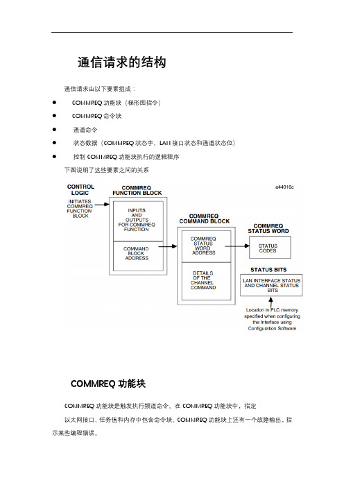
通信请求的结构通信请求由以下要素组成:● COMMREQ功能块(梯形图指令)● COMMREQ命令块● 通道命令● 状态数据(COMMREQ状态字、LAN接口状态和通道状态位)● 控制COMMREQ功能块执行的逻辑程序下图说明了这些要素之间的关系COMMREQ功能块COMMREQ功能块是触发执行频道命令。
在COMMREQ功能块中,指定以太网接口、任务值和内存中包含命令块。
COMMREQ功能块上还有一个故障输出,指示某些编程错误。
COMMREQ命令块COMMREQ命令块是一个包含有关通道信息的结构要执行的命令。
命令块由两部分组成:公共区域-包括COMMREQ状态字(CRS字)的地址。
数据块区域-描述要执行的通道命令。
当COMMREQ功能启动时,命令块被传输到以太网操作界面。
Modbus/TCP通道命令通道命令是一组用于与服务器通信的客户端PLC命令。
一个90-30系列以太网接口最多可以建立16个通道(编号1-16)。
这个通道编号在通道命令的命令块中指定。
频道可以使用通道状态位监视状态数据客户机PLC逻辑程序有几种状态可用。
LAN接口状态位(LIS位):LIS位包括80位状态区域的位1–16。
这个此80位状态区域的位置是使用“状态”中的配置软件指定的地址”字段。
LIS位包含有关局域网(LAN)状态的信息以及以太网接口本身。
信道状态位:信道状态位包括80位状态的位17–80(64位)区域。
当用于Modbus/TCP通道时,这些位由一个连接打开位和一个未使用的位组成位,为可建立的16个通道中的每一个保留以供将来使用。
的状态位未使用的通道始终设置为零。
COMMREQ状态字(CRS字):16位CRS字将接收通信请求。
CRS字的位置分配给每个COMMREQ函数在COMMREQ命令块中。
COMMREQ功能块的FT输出:此输出表示检测到PLC CPUCOMMREQ功能块和/或命令块出错,未传递命令块到以太网接口。
modbus tcp讲解 -回复
modbus tcp讲解-回复什么是Modbus TCP?Modbus TCP是一种通信协议,用于在以太网上实现Modbus通信。
Modbus是一种串行通信协议,通常用于连接工业自动化设备。
Modbus TCP是基于TCP/IP协议栈的,使得Modbus可以在以太网上进行通信。
Modbus TCP的工作原理Modbus TCP协议基于客户端-服务器模型工作。
客户端是发送请求的设备,而服务器是响应请求的设备。
客户端和服务器之间通过以太网连接进行通信。
在Modbus TCP通信中,客户端发送一个请求包给服务器。
请求包包含了要求的读取或写入的数据以及其他相关信息,例如数据地址和数据长度。
请求包被传输到服务器,然后服务器对请求进行处理,并返回响应包给客户端。
响应包包含了请求的结果和其他必要的信息。
Modbus TCP通信的好处Modbus TCP具有以下几个好处:1. 网络可扩展性:由于Modbus TCP使用以太网作为物理媒介,因此它具有很好的网络可扩展性。
在现代工业自动化中,往往需要处理大量设备和数据,Modbus TCP可以轻松地扩展以满足需求。
2. 简单性:Modbus TCP是一种简单且易于实现的协议。
它使用标准的TCP/IP协议栈,因此设备可以使用现有的以太网硬件和软件进行通信。
此外,Modbus TCP的数据格式和通信规范也相对简单明了。
3. 兼容性:Modbus TCP可以兼容不同类型的设备。
无论设备是基于Windows、Linux还是其他操作系统,只要支持TCP/IP协议栈,就可以使用Modbus TCP进行通信。
4. 实时性:Modbus TCP使用以太网作为物理媒介,具有较高的传输速度和较低的延迟。
这使得Modbus TCP成为支持实时通信的一种有效选择。
应用领域Modbus TCP常被应用于工业自动化领域,用于连接各种设备和系统。
以下是几个典型的应用领域:1. 温度控制系统:Modbus TCP可以用于连接温度传感器和温度调节设备,实现对温度的监测和调控。
GE-Modbus-TCP
U PON COMPLETION OF THIS MODULE, YOU SHOULD BE ABLE TO:• Configure the Modbus/TCP Server controller• Describe how communication is established between the Client and the Server• Interpret the COMMREQ settings in the Client controller• Interface with the project using the QuickPanel on the PACSystems demo unitModbus TCPModbus TCPOverview - Modbus/TCP ServeThe PACSystems products listed below support Modbus/TCP Server functionality:• CPU010 and CPU020 with primary firmware version 3.0 or later.• CRE020 with Ethernet firmware version 3.0 or later.• RX7i: IC698ETM001 and RX3i IC695ETM001 with firmware version 3.0 or later.Modbus/TCP Server ConnectionsThe Modbus/TCP Server supports up to 16 simultaneous connections. These connections are not shared with any other applications. Other TCP-based application protocols such as SRTP Server use a different set of TCP connections.Modbus Conformance ClassesPACSystems Modbus/TCP Server supports Modbus Conformance classes 0, 1, and 2.The RX3i Ethernet module has been certified by the Modbus/TCP Conformance Test Laboratory to be in conformance with Conformance Test Policy Version 2.1.Address ConfigurationAddress mapping is done in the Machine Edition Hardware Configuration of the CPU. All Ethernet modules and daughter-boards in the PLC use Modbus-to-PLC address mapping based on this one map. The Modbus/TCP Server does not use COMMREQs to configure address mapping.Each PLC memory area is mapped to an appropriate Modbus address space. On the Settings tab, Modbus Address Space Mapping can be set to Standard Modbus Addressing or Disabled. If Modbus Address Space Mapping is set to Standard, the Modbus/TCP Address Map tab displays the standard references assignments.Figure 10-1. Address MappingModbus TCPModbus Function CodesThis section summarizes the mapping of PACSystems reference tables to Modbus addresses by the Modbus function codes supported by the Modbus/TCP Server. The mapping shown in this table assumes that the PLC is configured to use its default reference table sizes.Figure 10-2. Modbus Function CodesModbus/TCP ClientCommunications to the Modbus/TCP Server are initiated by the Modbus/TCP client. The client first opens a communication channel via a communications request (COMMREQ) written in the client’s program. Once the communication channel has been opened the client reads or writes data to/from the server via a second COMMREQ. When the client has finished reading and/or writing data the communication channel is closed via another COMMREQ. All of the COMMREQ’s are programmed in the client controller.Structure of the Communications RequestThe Communications Request is made up of the following elements:• The COMMREQ Function Block (ladder instruction)• The COMMREQ Command Block• The Channel Command• Status Data (COMMREQ Status word, LAN Interface Status and Channel Status bits)• The logic program controlling execution of the COMMREQ Function BlockModbus TCP The figure below illustrates the relationship of these elements:Figure 10-3. Elements of the Communications RequestCOMMREQ Command BlockThe COMMREQ Command Block is a structure that contains information about the Channelcommand to be executed. The Command Block consists of two parts:Common Area - includes the address of the COMMREQ Status word (CRS word).Data Block Area - describes the Channel command to be executed.When the COMMREQ function is initiated, the Command Block is transferred to the Ethernetinterface for action.Modbus/TCP Channel CommandsThe Channel commands are a set of client commands used to communicate with a server. Up to 32 channels (numbered 1–32) can be established. The channel number is specified inthe Command Block for the Channel command. The channel can be monitored using theChannel Status bits. The 32 Client connections of an Ethernet interface are shared between all Client protocols. For example, if 16 Client connections are used for SRTP Channels, thereare 16 Client connections available for Modbus/TCP Channels. Any given channel can beassigned to only one protocol at a time.Status DataThere are several types of status available to the client application program.LAN Interface Status Bits (LIS Bits): The LIS bits comprise bits 1–16 of the 80-bit status area.The location of this 80-bit status area is assigned using the Configuration software. The LISbits contain information on the status of the Local Area Network (LAN) and the Ethernet interface.Modbus TCPChannel Status Bits: The Channel Status bits comprise bits 17–80 (64 bits) of the 80-bit status area. When used for Modbus/TCP channels, these bits consist of a connection open bit and a unused bit, reserved for future use, for each of the 16 channels that can be established.Status bits for unused channels are always set to zero.COMMREQ Status Word (CRS Word): The 16-bit CRS word will receive the initial status of the communication request. The location of the CRS word is assigned for each COMMREQ function in the COMMREQ Command Block.FT Output of the COMMREQ Function Block: This output indicates that the PLC CPU detected errors in the COMMREQ Function Block and/or Command Block and did not pass the Command Block to the Ethernet interface.The Logic Program Controlling Execution of the COMMREQ Function Block The COMMREQ must be initiated by a one-shot to prevent the COMMREQ from being executed repeatedly each CPU scan, which would overrun the capability of the Ethernet interface and possibly require a manual restart. Checking certain status bits before initiating a COMMREQ function is also important. In particular, the LAN Interface OK bit should be used as an interlock to prevent execution of the COMMREQ function when the Ethernet interface is not operational. Following initiation of a COMMREQ on a channel, no further COMMREQ’s should be issued to that channel until a non-zero CRS word has been returned to the program from the Ethernet interface.Operation of the Communications Request• A Communications Request begins when there is power flow to a COMMREQ function in the client. The Command Block data is sent from the CPU to the Ethernet interface.• The COMMREQ Status word (CRS word) is returned immediately if the Command Block is invalid. If the syntax is correct, then the CRS word is returned after the transfer of data. The COMMREQ Function BlockThe Communications Request is triggered when the logic program passes power to the COMMREQ Function Block.Figure 10-4. The COMMREQ Function BlockModbus TCP Each of the inputs and outputs are discussed in detail below. It is important to understand that the Command Block address points to the location in memory you have setup as the Command Block.Enable: Control logic for activating the COMMREQ Function Block. See Section 5 for tips on developing your program.IN: The location of the Command Block. It can be any valid address within a word-oriented area of memory (%R, %AI, %AQ, %P, %L or %W for the Ethernet interface).SYSID: A hexadecimal word value that gives the rack (high byte) and slot (low byte) location of the Ethernet interface.Figure 10-5. Hex Format of Rack and Slot Location of Ethernet InterfaceTASK: For the RX3i and Rx7i ETM001 Ethernet interfaces TASK must always be set to zero. For PACSystems CPU embedded Ethernet interface, TASK must be set to 65536 (0x10000) to address the CPU’s Ethernet daughterboard.FT Output: The FT output is set if the PLC CPU (rather than the Ethernet interface) detects that the COMMREQ fails. In this case, the other status indicators are not updated for this COMMREQ.The COMMREQ Command BlockFigure 10-6. COMMREQ Command Block StructureModbus TCP(Word 1) Data Block Length: This is the length in words of the Data Block portion of the Command Block. The Data Block portion starts at Word 7 of the Command Block. The length is measured from the beginning of the Data Block at Word 7, not from the beginning of the Command Block. The correct value for each command, and the associated length of each command, is specified in the next section.(Word 2) WAIT/NOWAIT Flag: This flag must be set to zero for TCP/IP Ethernet Communications.COMMREQ Status Word: The Ethernet interface updates the CRS word to show success or failure of the command. Command words 3 and 4 specify the PLC memory location of the CRSW word.(Word 3) COMMREQ Status Word Memory Type: This word specifies the memory type for the CRS word. The memory types are listed in the table below:Figure 10-7. COMMREQ Status Word Memory type(Word 4) COMMREQ Status Word Address Offset: This word contains the offset within the memory type selected. The status word address offset is a zero-based number.For example, if you want %R1 as the location of the CRS word, you must specify a zero for the offset. The offset for %R100 would be 99 decimal. Note, however, that this is the only zero-based field in the Channel commands.(Word 5): Reserved. Set to zero.(Word 6): Reserved. Set to zero.(Words 7 and up) Data Block: The Data Block defines the Channel command to be performed.Modbus TCPModbus/TCP Channel Commands• Open a Modbus/TCP Connection• Close a Modbus/TCP Connection• Read Data from a Modbus Server Device to the PLC• Write Data from the PLC to a Modbus Server Device• Mask Write Register Request to a Modbus Server Device• Read/Write Multiple Registers between PLC memory and a Modbus Server Device Please note that Modbus/TCP channel COMMREQs (unlike SRTP channel COMMREQs) do not contain a parameter to configure a timeout value. Enforcing a timeout for a Modbus channel command is at the discretion of the user and must be implemented in the userapplication.Command 3000 ExampleEstablish a channel (Channel 5) to a remote Modbus/TCP device at IP address 10.0.0.1. Return the COMMREQ Status word to %R10.Dec (Hex)Word 1 00008 (0008) Length of Channel command Data BlockWord 2 00000 (0000) Always 0 (no-wait mode request)Word 3 00008 (0008) Memory type of CRS word (%R)Word 4 00009 (0009) CRS word address minus 1 (%R10)Word 5 00000 (0000) ReservedWord 6 00000 (0000) ReservedWord 7 03000 (0BB8) Open Modbus/TCP Client ConnectionWord 8 00005 (0005) Channel number (5)Word 9 00001 (0001) Remote Device Address TypeWord 10 00004 (0004) Length of Remote Device AddressWord 11 00010 (0010) Numeric value of 1st OctetWord 12 00000 (0000) Numeric value of 2nd OctetWord 13 00000 (0000) Numeric value of 3rd OctetWord 14 00001 (0001) Numeric value of 4th OctetCommand 3001 ExampleTerminate the Modbus/TCP Client connection established on Channel 5.Return the COMMREQ Status word to %R10.Modbus TCPDec (Hex)Word 1 00002 (0002) Length of Channel command Data BlockWord 2 00000 (0000) Always 0 (no-wait mode request)Word 3 00008 (0008) Memory type of CRS word (%R)Word 4 00009 (0009) CRS word address minus 1 (%R10)Word 5 00000 (0000) ReservedWord 6 00000 (0000) ReservedWord 7 03001 (0BB9) Close Modbus/TCP Client ConnectionWord 8 00005 (0005) Channel number (5)Read Data from a Modbus/TCP Device (3003)The Read Data from a Modbus/TCP Device COMMREQ requests a data transfer from a Modbus/TCP device to the PLC. The Read Data COMMREQ must reference an active Modbus/TCP channel previously established with the Open Modbus/TCP Client Connection COMMREQ.Registers, Coils or Exception Status data may be read from the remote Modbus/TCP device.The Modbus Function Code specifies the data type. Valid Function Codes for the Read Data COMMREQ are presented in the following table:Figure 10-8. Modbus Function CodesCommand 3003 ExampleRead four Input Registers from Input Registers in the remote Modbus/TCP device. Store the registers at location %R20. Return the COMMREQ Status word to %R10.Dec (Hex)Word 1 00008 (0008) Length of Channel command Data BlockWord 2 00000 (0000) Always 0 (no-wait mode request)Word 3 00008 (0008) Memory type of CRS word (%R)Word 4 00009 (0009) CRS word address minus 1 (%R10) *Word 5 00000 (0000) ReservedWord 6 00000 (0000) ReservedWord 7 03003 (0BBB) Read from a Modbus/TCP DeviceWord 8 00006 (0006) Channel number (6)Word 9 00004 (0004) Modbus Function Code (Read Input Registers)Word 10 00008 (0008) Local PLC Memory TypeWord 11 00020 (0014) Local PLC Starting AddressWord 12 00200 (00C8) Address in the Remote ServerWord 13 00004 (0004) Number of Registers in the Remote DeviceWord 14 00001 (0001) Unit Identifier* Word 4 (CRS word address) is the only zero-based address in the Command Block. Only this value requires subtracting 1 from the intended address.Local PLC Memory Type: Words 10-11 specify the location in the local PLC where the Ethernet interface will store data received from the remote device Valid values for Word 10 are listed below.Figure 10-9.Valid Values for Local PLC Memory TypeLab Exercise – Using Modbus/TCP ProtocolIn this lab you will be reading and writing data from the Client controller to/from the Server controller via the Modbus/TCP protocol.This lab assumes the following hardware configuration and setup. The IP Addresses defined below are used in the Project provided with this lab.1. Double-click on the project called DiscCafe_ModbusTCP in the Navigator window toopen it.2. Open the hardware configuration of the controller target labeled Server.3. Double-click on the CPU module to open its’ configuration window.4. Under the Settings tab you will see that this controller has been configured for StandardModbus Addressing.5. Click on the tab labeled Modbus TCP Address Map. Here you will see how the Modbusregister memory has been mapped to the PAC Rx3i memory.6. Close the Server configuration window.7. Next, open the Logic section of the target labeled Client.8. Double-click on the _MAIN program block to open it in the editor window.9. The ladder logic in the _MAIN program block has comments that describe what the first2 rungs do.10. Next, double-click on the block called TCP_READ.11. There are 3 steps of logic in this block.a) Open a communication channel between the Client and the Server.b) Read data from the Server.c) Close the communication channel.12. Scroll through the logic in this block and read the comments that describe the operationof the block.13. Next double-click on the block called TCP_WRITE.14. There are 3 steps of logic in this block also.a) Open a communication channel between the Client and the Server.b) Write data to the Server.c) Close the communication channel.15. Scroll through the logic in this block and read the comments that describe the operationof the block.16. Next you will need to download to each of the 4 targets in this project. Right-click on theClient target and select Set as Active Target from the menu.17. Now, right-click on the Client target and select Go Online from the menu, or press theOnline/Offline toolbar button .18. Next, right-click and select the Online Commands, Set Programmer Mode menu, orpress the Toggle Online Mode toolbar button .19. Next, select the Online Commands, Stop PLC menu, or press the Stop Active Targettoolbar button .20. Click OK.21. Right-click and select the Download to PLC menu, or press the F8 function key, or pressthe Download Active Target toolbar button .22. Check to make sure that the boxes are checked as shown below and then click OK.23. Select the Online Commands, Start PLC menu, or press the Start Active Target toolbarbutton .24. Click OK.25. Check the information displayed on the Status Bar to verify that the PACSystemscontroller is in Run Mode, and that the Configuration and Logic are both Equa l.26. Right-click on the Client target and select Go Offline from the menu.27. Next, repeat steps 16 through 26 for the Server target.Once you have successfully downloaded and started the Client and Server controllers, you will use the QuickPanels to exercise the application.But first, you need to download both QuickPanel applications to the demo units.28. Right-click on the Client_QP target and select Set as Active Target from the menu.29. Right-click on the Client_QP target and select Download and Start from the menu, orpress the F9 function key, or press the Download and Start Active Target toolbar button .30. Next, repeat steps 28 and 29 for the Server_QP target.31. Now you will read and write some data using the QuickPanels on the PACSystemsdemo units.32. First go to the QuickPanel whose screen is labeled Modbus/TCP Server.33. Touch the Numerical Data Entry box labeled Value_1 and enter a value between 0 and32767 by using the pop-up keypad.34. Click OK on the keypad when you have finished.35. Enter a number for Value_2 in the same manner.36. Next, go to the QuickPanel whose screen is labeled Modbus/TCP Client.37. Touch the button labeled Read and the values that you entered on the Modbus/TCPServer screen will be read from the Server PAC controller and displayed on the Client’s QuickPanel screen as Value_1 and Value_2.38. Next, enter a number for Value_3 and Value_4 from the Client screen.39. Now touch the button labeled Write and these values will be written to the Server PACcontroller and displayed on the Server’s QuickPanel screen as Value_3 and Value_4.40. Touching the button labeled Reset will clear the values on the Modbus/TCP Clientscreen so that another Read/Write can be performed.Review:In this lab, you have been shown how:• A PACSystems controller can be configured as a Modbus/TCP Server• A PACSystems controller can act as a Modbus/TCP Client to read and write data from/to a Modbus/TCP Server device• The logic to perform the read/write is configured• Reads/writes can be executed from a graphical interface。
MODBUS TCP通讯协议在PLC与串口服务器的通讯应用
209MODBUS TCP 通讯协议在PLC 与串口服务器的通讯应用马永钧,王彦龙(北京源深节能技术有限责任公司,北京海淀100142)摘要:文章介绍了MODBUS 通讯协议的PLC 与串口服务器的通讯应用。
主要包括MODBUS TCP 通讯原理、串口服务器的通讯配置、PLC 组态配置和软件通讯实现等内容。
实践表明,该系统具有良好的实时性和可靠性。
关键词:MODBUS TCP ;通讯;PLC ;串口服务器中图分类号:TP393.05文献标识码:A 文章编号:1673-1131(2016)10-0209-020引言在工业企业中,集散控制系统(DCS )与可编程逻辑控制器(PLC )、数据采集器和各种智能仪表通过控制网络相互组合构成完整的自动化控制系统。
现场设备通常采用RS-232和RS-485总线进行连接,但是随着工业企业对自动化应用的实时性需求日益提高,工业以太网在自动化领域被广泛应用,取代串口通讯已成为自动化系统的一种趋势。
为了保护对现有设备的投资,同时满足用户对数据通讯处理能力的要求,就需要将原有串口通讯转换成工业以太网通讯,而串口服务器是设备硬件串口转以太网连接的桥梁,它能将传统的串行数据变成基于TCP/IP 协议的报文数据。
基于MODBUS TCP 协议的工业以太网连接方便,现场较容易实施,TCP/IP 协议的基础上在应用层使用MODBUS TCP 通讯协议,就能实现使用工业以太网进行数据实时交换,将大量的数据传输到实时监控网和管理网。
本文深入研究了MODBUS TCP 通讯协议,对MODBUS TCP 通讯原理、串口服务器的通讯设置、PLC 的组态配置和控制逻辑实现进行了详细说明。
1MODBUS TCP 协议MODBUS 协议是工业控制领域中最流行的通讯协议,它支持传统的RS232、RS422、RS485和以太网设备。
MODBUS 协议有两种通讯方式,既RTU (远程终端)方式和ASCII 方式。
BX9000的Modbus TCP通讯
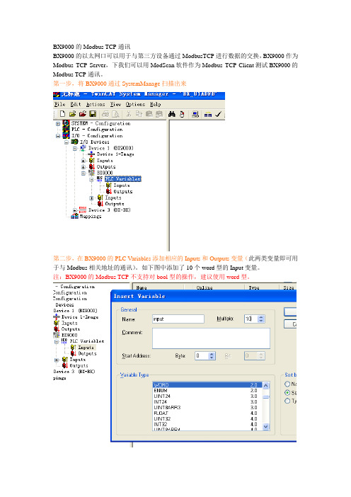
BX9000的Modbus TCP通讯BX9000的以太网口可以用于与第三方设备通过ModbusTCP进行数据的交换,BX9000作为Modbus TCP Server,下我们可以用ModScan软件作为Modbus TCP Client测试BX9000的Modbus TCP通讯。
第一步,将BX9000通过SystemManage扫描出来第二步,在BX9000的PLC Variables添加相应的Inputs和Outputs变量(此两类变量即可用于与Modbus相关地址的通讯)。
如下图中添加了10个word型的Input变量。
注:BX9000的Modbus TCP不支持对bool型的操作,建议使用word型。
变量添加完成后,如下图所示。
第三步,编写PLC程序并作变量链接上图中为将PLC程序中的数组变量input与PLC Variables的input变量链接。
同时也要对output变量做相应的链接。
完成变量链接后即可将System Manager激活(Activate Configuration),然后将PLC程序下载。
第四步,运行ModScan软件,对相关数据区测试(ModbusTCP通讯需填写BX9000的IP 地址以及端口号502)上图为测试Modbus地址3x0001~3x0010对应了PLC中的Output数组的各个值,此类型数据可进行双向传输。
对于Input变量,则只能接受ModScan发出的数据,并且其对应的为3x2049开始的Modbus地址。
注:在对BX9000做Modbus地址写操作前,需要先对地址3x4386依次写入十六进制值0xBECF和0xAFFE(用于对BX9000的watchdog复位),如不做watchdog复位,则写值时会提示无Modbus应答或应答有误。
对于PLC中MW0的值,可以对Modbus地址3x16385操作即可。
下面列出BX9000的Modbus TCP通讯的地址对应关系:Modbus地址BX9000变量备注0001~0126 PLC Variable Inputs System Manager中添加并链接2049~42174 PLC Variable Outputs System Manager中添加并链接16385~18431 MW0~MW4094 PLC中定义。
Modbus通信通讯教程(详细)

U-01DM/G-01DM 异步串行
图(1-6):主要厂牌通信协议表
3.2 Modbus 通信协议的由来 Modbus 通信协议,是 Modicon PLC 所制定的资料交换通信接口标准, 于 1979 年首先制定串行通信标准(含 Modbus 异步及 Modbus Plus 同步), 于 1997 年制定网络通信标准(Modbus/TCP)。是属于 OSI 所定义的通信层
第一章: 控制设备通信慨况
1 慨念说明 于自动控制系统的各种设备,相互之间的通信及资料交换是非常重要
的基本功能之一。早期通信方式是使用串行式硬件架构,然后定义通信步 骤及资料格式等基本通信规格,也就是通信协议(Communication Protocol)。外部计算机依据此通信协议即可与该自控设备读取或写入资 料。也可以看做读取该控制设备所控制的结果,写入一些控制命令要求该 控制设备执行所指定的功能。
8字节6字节6字节2字节461500字节crcdataframetype来源地址目的地址前置4字节wwwplcworldcn以modbustcp的通信协议资料格式除了再加上前面6byte做网络用资料其后面的资料与modbus232完全一样设计tcp应用程序反而依照socket方式就可以收送资料不像rs232应用程序必须处理所有步骤例如
PLC(Programmable Logical Controller)是自动控制系统的核心设备, 肩负着主要的控制功能,所以 PLC 对外通信能力也是格外的重要。各种厂 牌的 PLC 都会制定自有的通信协议接口标准。其中 Modbus 通信协议是 Modicon PLC 所定义的通信协议。因为 Modicon 是最早开发出 PLC 的设 备,故其所制定的通信协议,也广泛被其它厂商所接受,无形中成为自控 界主流的通信协议。
modbus tcp协议报文解析

modbus tcp协议报文解析【原创实用版】目录一、Modbus TCP 协议简介二、Modbus TCP 报文结构1.请求报文结构2.响应报文结构三、Modbus TCP 报文解析实例四、Modbus TCP 通信的应用场景正文一、Modbus TCP 协议简介Modbus TCP 协议是一种串行通信协议,它基于 TCP/IP 协议族,用于在工业自动化领域实现设备之间的通信。
Modbus TCP 协议继承了Modbus RTU 协议的优点,具有传输速度快、通信可靠性高、扩展性强等特点。
在工业自动化系统中,Modbus TCP 协议广泛应用于 PLC、PAC、智能仪表等设备之间的通信。
二、Modbus TCP 报文结构Modbus TCP 报文分为请求报文和响应报文两种。
请求报文由客户端发送给服务器,响应报文由服务器发送给客户端。
1.请求报文结构请求报文的结构如下:- 事务处理标识符:用于区分不同的通信数据报文,每次通信后加 1。
- 协议标识符:00 00,表示 Modbus 协议。
- 数据长度:指示接下来数据的长度,单位为字节。
- 设备地址:用于标识连接在串行线或网络上的远程服务端的地址。
- 功能码:指示请求的操作类型,例如读取保持寄存器数据。
- 起始地址:指示读取数据的起始地址。
- 寄存器数量:指示需要读取的寄存器数量。
2.响应报文结构响应报文的结构如下:- 事务处理标识符:与请求报文中的事务处理标识符相同。
- 协议标识符:与请求报文中的协议标识符相同。
- 数据长度:指示接下来数据的长度,单位为字节。
- 设备地址:与请求报文中的设备地址相同。
- 功能码:与请求报文中的功能码相同。
- 数据字节长度:指示接下来数据的字节长度。
- 数据值:表示被读取的保持寄存器中的数据值。
三、Modbus TCP 报文解析实例假设客户端向服务器发送一个读取保持寄存器数据的请求,请求报文如下:```00 00 00 00 00 06 09 03 00 00 00 01```服务器接收到请求后,返回一个响应报文:```00 00 00 00 00 05 09 03 02 12 34```响应报文中,设备地址、协议标识符、事务处理标识符和功能码都与请求报文相同。
使用vfbox网关采集倍福PLC数据-转-modbus从站操作说明V1.3

目录1文档说明 (1)2准备工作 (1)3设置倍福PLC (1)4配置网关参数 (3)5用MODBUS协议转发数据 (6)1文档说明1.设置倍福PLC,开通ADS通信2.设置网关采集倍福PLC数据3.把采集的数据转成modbus从站协议转发给其他系统。
2准备工作1.仰科网关。
支持采集倍福PLC数据,Modbus从站协议转发。
2.电脑。
IP设置成192.168.1.198,和网关在同一个网段。
3.网线、12V电源。
3设置倍福PLC1.状态栏,TwinCAT图标,右键,TwinCAT XAE(VS2017)2.Visual Studio打开TwinCAT工程文件3.解决方案资源管理器,Routers,NetId Management,记录下Local NetId(VFBOX Studio中需要使用)4.解决方案资源管理器,Routers,Static Routers,Add…,Add Route样例AMS route:Route Name(Target): M yAdsClientAMSNetId:192.168.1.199.1.1 # 网关IP.1.1Transport Type:TCP/IPAddress Info:192.168.1.199 # 网关IPTarget Route:StaticRemote Route:None / ServerUnidirectional:falseSecure ADS:falsePassword:留空5.Visual Studio保存工程,菜单TwinCAT, Activate Configuration4配置网关参数1.安装VFBOXStudio软件。
打开软件后,点击“新建工程”,设备类型选择实际网关的型号。
可查看网关背面标签。
2.3.点击“新建设备”,驱动类型选择如下:4.5.输入PLC的IP地址和端口。
默认端口是48898.6.7.输入ADS的参数,从来PLC上获取。
- 1、下载文档前请自行甄别文档内容的完整性,平台不提供额外的编辑、内容补充、找答案等附加服务。
- 2、"仅部分预览"的文档,不可在线预览部分如存在完整性等问题,可反馈申请退款(可完整预览的文档不适用该条件!)。
- 3、如文档侵犯您的权益,请联系客服反馈,我们会尽快为您处理(人工客服工作时间:9:00-18:30)。
倍福BK9100/BC9000通过ModbusTCP与GE RX3i通讯一、试验目的:测试BK9100/BC9000和GE RX3i通过ModbusTCP的通讯功能。
二、试验时间和地点:2007年4月17日,4月25日,北京西通电子有限公司三、试验人员:王宁强(技术支持工程师,德国倍福自动化有限公司北京代表处)陈明辉(技术工程师,北京西通电子有限公司(GE授权分销商))四、试验设备:倍福产品清单:BK9100,1块BC9000,1块KL1002,2块KL2012,2块KL9010,2块KL3132,1块KL4132,1块GE产品清单:IC695CPU310-EL(RX3i),1块IC695ETM001-CC(以太网模块,10/100MBITS),1块IC695PSA040F(电源),1块五、试验步骤:(一)设置1.打开当前项目的Hardware Configuration2.双击Rack 0下的CPU(Slot2),并将右侧窗口中Settings标签下的最后一项设置如下图中红色框中所示:3.双击Rack 0下的以太网模块(Slot4),并将右侧窗口中Settings标签下的IP地址设置为与BC9000/BK9100在同一网段内,如图所示(同时BK9100的IP地址为192.168.0.7):(二)GE RX3i作为主站(Client)读写BK9100/BC9000 (Server)1.BC9000/BK9000 的ModbusTcp过程映像z输入过程映像从地址从0x0000开始 (对应于GE 功能块中的地址0x0001) 。
所有面向字节的总线端子优先输入到过程映像区中。
面向位的总线端子紧随其后。
z输出过程映像从地址从0x0800开始(对应于GE 功能块中的地址0x0801)。
所有面向字节的总线端子优先输入到过程映像区中。
面向位的总线端子紧随其后。
z Memory Flag过程映像从地址 0x4000开始。
(对应于GE 功能块中的地址0x4001)z所有的数字量信号可以直接使用功能 1,2,5 和 15 寻址。
(直接寻址意味着使用这几个功能时,数字量端子的映像地址从0x0000开始(对应于GE 功能块中的地址0x4001),不考虑面向字节的总线端子。
2.功能代码在GE PLC中,通过COMM_REQ功能块来发送请求:(COMM_REQ功能块的使用参见GE文档GFK2224D)功能代码1:z读取线圈状态,地址从0x0001开始(COMM_REQ的Command Block中的 word7=3003,word9=1,word12=线圈地址,word13=线圈数量(bits)) 功能代码2:z读取DI状态,地址从0x0001开始(COMM_REQ的Command Block中的 word7=3003,word9=2,word12=DI地址,word13=DI数量(bits)) 功能代码3:z读取寄存器(Memory Flag),地址从0x4001开始(COMM_REQ的Command Block 中的 word7=3003,word9=3,word12=M寄存器地址,word13=M寄存器数量(words))z读取AO,地址从0x0801开始,数字输出的地址排在所有面向字节的总线端子之后(COMM_REQ的Command Block中的 word7=3003,word9=3,word12=输出寄存器地址,word13=输出寄存器数量(words))功能代码4:z读取AI,地址从0x0001开始,数字输入的地址排在所有面向字节的总线端子之后(COMM_REQ的Command Block中的 word7=3003,word9=4,word12=输入寄存器地址,word13=输入寄存器数量(words))功能代码5:z写单个线圈,地址从0x0001开始(COMM_REQ的Command Block中的 word7=3004,word9=5,word12=线圈地址,word13=1线圈数量(bits))功能代码15:z写多个线圈,地址从0x0000开始(COMM_REQ的Command Block中的 word7=3004,word9=15,word12=线圈地址,word13=线圈数量(bits))功能代码6:z写单个寄存器,地址从0x4001开始(COMM_REQ的Command Block中的 word7=3004,word9=6,word12=M寄存器地址,word13=1M寄存器数量(bits)) z写单个AO寄存器,地址从0x0801开始,数字输出的地址排在所有面向字节的总线端子之后(COMM_REQ的Command Block中的 word7=3004,word9=6,word12=输出寄存器地址,word13=1输出寄存器数量(words))功能代码16:z写多个寄存器,地址从0x4001开始(COMM_REQ的Command Block中的 word7=3004,word9=16,word12=M寄存器地址,word13=M寄存器数量(bits)) z写多个AO寄存器,地址从0x0801开始,数字输出的地址排在所有面向字节的总线端子之后(COMM_REQ的Command Block中的 word7=3004,word9=16,word12=输出寄存器地址,word13=输出寄存器数量(words))3.程序示例:z Open a Modbus/TCP Client Connection (3000)z Send Request to Modbus/TCP Server(3003,3004)Open a Modbus/TCP Client ConnectionSend Request to Modbus/TCP Server(三)PC/BC9000作为主站(Client)读写GE RX3i (Server)1.GE RX3i的ModbusTcp映像地址z Q区(数字输出):地址从0x0001开始(对应于BC功能块中的地址0x0000)z I区(数字输入):地址从0x0001开始(对应于BC功能块中的地址0x0000)z AI区(模拟输入):地址从0x0001开始(对应于BC功能块中的地址0x0000)z R区(寄存器):地址从0x0001开始(对应于BC功能块中的地址0x0000)z模拟输出不能读写,但是可以通过R区间接读写。
(GE PLC中的Modbus寄存器表完全映像到R区)2.功能代码在BC中,通过FB_ModbusTcpRequest功能块来发送请求:(该功能块的使用参见TwinCAT PLC帮助文档)功能代码1:z读取线圈状态,地址从0x0000开始功能代码2:z读取DI状态,地址从0x0000开始功能代码3:z读取寄存器(Memory Flag),地址从0x0000开始功能代码4:z读取AI,地址从0x0000开始功能代码5:z写单个线圈,地址从0x0000开始功能代码15:z写多个线圈,地址从0x0000开始功能代码6:z写单个寄存器,地址从0x0000开始功能代码16:z写多个寄存器,地址从0x4000开始3.BC9000程序示例:PROGRAM MAINV AR:FB_ModbusTcpOpen;ModbusTCP_OpenModbusTCP_Request :FB_ModbusTcpRequest;bStartOpen :BOOL:=FALSE;BK_IPAddress :STRING(15):='192.168.0.1';bBusyOpen :BOOL;bErrorOpen :BOOL;:WORD;iErrorIDConnection :WORD:=0;:BOOL :=FALSE;bStartRequest:BOOL;bBusyRequest:BOOL;bErrorRequestiErrorIDRequest :WORD;cbResponse :WORD;BYTE :=1,3,0,0,0,2;SendBuffer :ARRAY[0..5]OF*)Unit Identifier(*1:功能号,此时为读寄存器 *)(*3:(*0,0: 起始地址高,低字节 *)(*0,2: 数据长度高,低字节 *)OFBYTE;:ARRAY[0..255]ReceiveBufferEND_V ARModbusTCP_Open( bStart :=bStartOpen,sRemoteIPAddr :=BK_IPAddress,tTimeOut :=t#2S);bBusyOpen :=ModbusTCP_Open.bBusy;bErrorOpen :=ModbusTCP_Open.bError;iErrorID :=ModbusTCP_Open.iErrorId;Connection :=ModbusTCP_Open.iMyPortNo;bStartOpen :=(Connection=0)AND(NOT bStartOpen)AND(NOT bBusyOpen);bStart :=bStartRequest,ModbusTCP_Request(sRemoteIPAddr :=BK_IPAddress,iMyPortNo :=Connection,pReqBuff :=ADR(SendBuffer),cbReqLen :=SIZEOF(SendBuffer),pResBuff :=ADR(ReceiveBuffer),cbResLen :=SIZEOF(ReceiveBuffer)); bBusyRequest :=ModbusTCP_Request.bBusy ;bErrorRequest :=ModbusTCP_Request.bError;iErrorIDRequest :=ModbusTCP_Request.iErrorId ;cbResponse :=ModbusTCP_Request.cbResponse ;bStartRequest :=(Connection<>0)AND( NOT bStartRequest) AND (NOT bBusyRequest);六、结论:通过试验上述的ModbusTcp 功能均能够正常实现。
