LC插针接插件设计指南word文档
IQC接插件
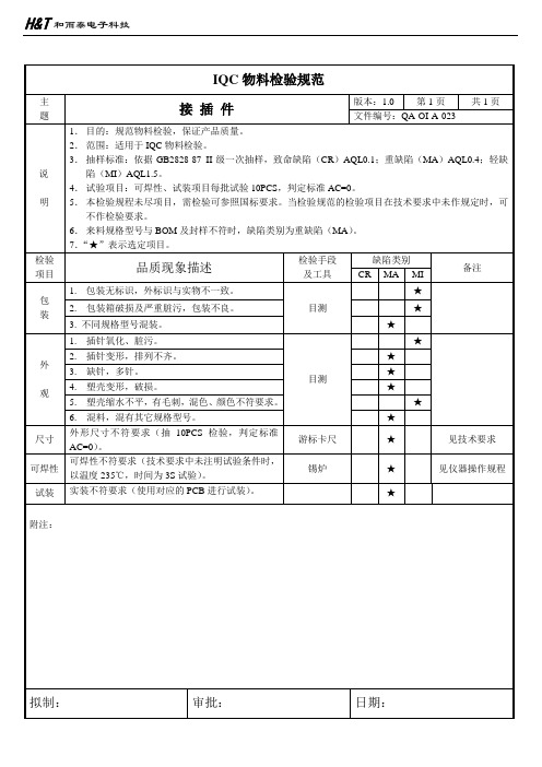
6.来料规格型号与BOM及封样不符时,缺陷类别为重缺陷(MA)。
7.“★”表示选定项目。
检验
项目
品质现象描述
检验手段
及工具缺陷类别备注CR NhomakorabeaMA
MI
包
装
1.包装无标识,外标识与实物不一致。
目测
★
2.包装箱破损及严重脏污,包装不良。
★
3.不同规格型号混装。
★
外
观
1.插针氧化、脏污。
目测
★
2.插针变形,排列不齐。
★
3.缺针,多针。
★
4.塑壳变形,破损。
★
5.塑壳缩水不平,有毛刺,混色、颜色不符要求。
★
6.混料,混有其它规格型号。
★
尺寸
外形尺寸不符要求(抽10PCS检验,判定标准AC=0)。
游标卡尺
★
见技术要求
可焊性
可焊性不符要求(技术要求中未注明试验条件时,以温度235℃,时间为3S试验)。
IQC物料检验规范
主
题
接插件
版本:1.0
第1页
共1页
文件编号:QA-OI-A-023
说
明
1.目的:规范物料检验,保证产品质量。
2.范围:适用于IQC物料检验。
3.抽样标准:依据GB2828-87 II级一次抽样,致命缺陷(CR)AQL0.1;重缺陷(MA)AQL0.4;轻缺陷(MI)AQL1.5。
4.试验项目:可焊性、试装项目每批试验10PCS,判定标准AC=0。
锡炉
★
见仪器操作规程
试装
连接器设计手册要点
连接器设计手册要点1.介绍连接器的基本知识:连接器的定义、组成部分、分类和主要功能。
具体包括连接器的定义、连接器的分类、连接器的主要组成部分、连接器的功能。
2.详细介绍连接器的材料和制造工艺:不同材料和制造工艺对连接器性能的影响。
重点讨论连接器材料的选择、制造工艺的选择和连接器的成型工艺。
3.连接器的功能和性能参数:介绍连接器的功能和主要性能参数,如电气参数、机械参数、环境参数等。
重点讨论不同类型的连接器的特点,如信号连接器、电源连接器、数据连接器和光纤连接器。
4.连接器的设计原则和方法:介绍连接器设计的基本原则和方法,以确保设计的可靠性和可靠性。
重点讨论连接器的结构设计、接触设计、固定设计和环境适应性设计。
5.连接器的可靠性和可靠性测试:介绍连接器的可靠性要求和可靠性测试方法,以确保连接器在不同环境下的可靠和稳定性能。
重点讨论连接器的可靠性要求、可靠性测试方法和连接器寿命预测。
6.连接器的应用概述:介绍不同领域中连接器的应用,如电子设备、航空航天、汽车、通信等领域。
重点讨论连接器在不同应用领域中的特点和要求。
7.连接器的选型指南:提供连接器选型的指南和建议,以帮助工程师和设计师选择合适的连接器。
重点讨论连接器的选型原则、选型流程和选型考虑因素。
8.连接器的故障分析和故障排除:介绍连接器的常见故障分析和故障排除方法,以解决连接器在使用过程中出现的问题。
重点讨论连接器的常见故障、故障分析方法和故障排除方法。
9.连接器的未来发展趋势和挑战:展望连接器的未来发展趋势和面临的挑战,如高速连接器、微型连接器和无线连接器等。
重点讨论连接器的发展趋势、面临的挑战和未来方向。
10.关键参考:提供连接器设计和应用方面的关键参考资料和文献,在连接器设计和应用过程中提供指导和支持。
连接器设计手册是连接器设计和应用领域的权威参考,对工程师和设计师来说是一本必备的工具书。
通过掌握手册中的要点,工程师和设计师可以更好地理解连接器的性能和特点,选择适合的连接器,并进行有效的设计和应用。
(完整word版)接线端子插接插件和各类连接器的基础知识

接线端子和各类连接器的基础知识接线端子用于将分开的电路连接到一起。
通常这些连接器用于常需要切换和断开的场合,如连接电源,连接外围电路,或者需要更换的扩展部分。
该教程涵盖内容在本教程中,我们将介绍下面主题•关于接线端子的常见术语•将接线端子进行区别分类•介绍上述分类之间的区别•介绍如何使用极性防反的接线端子•介绍如何使用极性防反的接线端子建议先阅读在您开始阅读本文之前,请确保您已经知道或者学习了以下教程中所罗列的内容:•什么是电路?(What is a circuit?)•电压、电流、电阻和欧姆定律(Voltage, Current,Resistance and Ohm’s Law)•导线的基础知识(Working with Wire)•极性和极性元件(Polarity)•如何给项目供电(Powering Your Project)接线端子术语在我们开始讨论一些常用的连接器之前,让我们来探讨用于描述接线端子的术语.公母端子Gender–接线端子的公母性说明了它是用来插入还是被插入的。
(哈哈,如果你还是单纯的孩子,更详细的解释估计你得去问问你父母)遗憾的是,有些被称为公头的端子,实际上是按照母头的端子来使用的。
在接下来的示例中,我们将将说明这些缘由。
Male and female 2。
0mm PH series JST connectors左边公右边母的 2。
0mm PH系列的JSP接线端子极性—大多数接线端子有约定的极性方向.这种特性使得接线端子可以防止接反。
North America wall plug 有极性的美规墙上插头。
通过为插头叶片两种不同的宽度,插头只能单向进入插座触点—触点是接线端子真正起作用的功能部分。
它们是彼此接触的金属部件,形成电气导通的连接。
这里也往往是导致连接不良的地方:触点可能变脏或氧化、或者金属弹片的弹性随时间蠕化变小而将导致触点松脱或连接不可靠.ADH8066 mating connector该连接器上的触点清晰可见.间距–许多连接器由重复排列的一组触点组成。
连接器设计手册
连接器设计手册连接器是一种常见的电气元件,它在电路中起着连接、传输信号和电能的重要作用。
在电子设备、通信设备、汽车、航空航天、电力设备等领域都广泛应用。
连接器设计手册是连接器设计工程师必备的参考资料,它包含了连接器的设计原理、规范标准、性能测试方法、制造工艺等方面的内容。
通过研读连接器设计手册,设计工程师可以了解连接器的工作原理和特性,从而在实际应用中选择合适的连接器,并进行连接器的设计和生产。
连接器设计手册首先介绍了连接器的分类和基本概念。
根据连接器的结构和用途不同,连接器可以分为板对板连接器、线对线连接器、线对板连接器、特种连接器等。
每种连接器都有其特定的应用场景和技术要求。
连接器设计手册详细介绍了各种连接器的结构、工作原理和特性,帮助设计工程师选择适合的连接器。
连接器设计手册还对连接器的电性能进行了详细介绍。
电性能是连接器的关键指标之一,包括电阻、电容、电感、接触电阻、绝缘电阻等。
连接器设计手册介绍了如何测试连接器的电性能,并提供了测试方法和标准。
设计工程师可以根据这些测试数据,选取合适的连接器,确保电流和信号的传输质量。
此外,连接器设计手册还介绍了连接器的机械性能和环境性能。
机械性能包括连接器的插拔次数、连接力、插入力、松动力等。
环境性能包括连接器的耐温、耐湿、耐腐蚀、耐震动等。
这些性能是连接器在实际应用中能否稳定工作的关键因素。
连接器设计手册提供了测试方法和标准,帮助设计工程师评估连接器的机械性能和环境性能。
最后,连接器设计手册还介绍了连接器的制造工艺和质量控制。
连接器的制造工艺涉及到模具设计、金属加工、注塑成型、插针插座设备等方面。
连接器设计手册提供了制造工艺的参考方案,帮助制造商提高生产效率和产品质量。
总之,连接器设计手册是连接器设计工程师十分重要的工具,它提供了连接器的基本概念、性能测试方法、制造工艺等方面的知识。
通过研读连接器设计手册,设计工程师可以选择适合的连接器、设计连接器布局、评估连接器的性能和质量,从而确保连接器在实际应用中的可靠性和稳定性。
最新元器件选型手册接插件部分-1

元器件选型手册接插件部分-1元器件选型手册(接插件部分)浙江正泰仪器仪表有限责任公司目录前言 (2)1.范围 (2)2.注意事项 (2)一、普通单双排插针 (3)二、普通单双排插座 (4)三、其他插针插座 (5)3.1蜈蚣插座 (5)3.2圆孔插座 (5)3.3DIP芯片插座 (6)3.4弯针 (6)四、线对板连接器 (7)4.1单排针座连接器 (7)4.2简牛针座 (10)4.3牛角针座 (10)五、USB接口 (11)六、天线及连接线 (12)七、其他类型接插件 (13)7.1FPC连接器 (13)7.2凤凰端子 (14)7.3PS2插座 (14)7.4DF12系列连接器 (14)7.5RJ45模块化插孔 (15)7.6IC卡座 (15)7.7SIM卡座 (15)前言1.范围本手册对公司目前使用的接插件进行了分类,对接插件的描述进行了定义。
本手册仅用于公司产品设计选型时参考。
2.注意事项➢本手册中部分物料因在规定的字符条件下无法描述清楚,故采用出图纸的方式,使用时,可以在PLM系统上直接查看或者下载。
➢本手册中物料描述的尺寸均未标明公差,如实际使用时对尺寸要求很高,请联系厂家出具规格承认书,或者参考GB/T 1804-2000。
➢所有物料的SAP描述均不能超过40个字符(包括空格)。
一、普通单双排插针1.1SAP描述规范双排单塑插针 2.54mm,2*14P,隔两排抽两排,针长16.5,深圳联颖①名称②脚间距③引脚数④(类型)⑤针尺寸⑥品牌①名称:单排单塑插针、双排单塑插针、单排双塑插针、双排双塑插针;②脚间距:一般为2.54mm或2mm;③引脚数:排数*单排引脚数;④(类型):如抽针,个别针加长等情况的说明,无特殊的可不写;⑤针尺寸:针长表示针两头之间的长度。
若PC=3mm默认不写,此时单塑插针,只需要写出针长;双塑插针,则需要写明针长和PA面长度;a1.2典型示例描述单排单塑插针 2.54mm,1*17P,PC=5,针长11.5,尤提乐对照图描述双排单塑插针 2.54mm,2*16P,针长18,尤提乐对照图描述单排双塑插针 2.54mm,1*4P,针长15.5,PA=PC=3,深圳联颖对照图描述双排双塑插针 2.54mm,2*15P,针长27,PA=9,尤提乐a PC面为针插入PCB的一端,PA面为远离PCB的一端。
连接器设计手册
连接器设计手册一、前言连接器是一种用于将电子设备或电路板连接在一起的部件,广泛应用于电子产品、通信设备、汽车、航空航天等领域。
连接器的设计对于设备的可靠性、性能以及系统的稳定性都具有重要意义。
本手册旨在介绍连接器设计的基本原理、设计考虑因素以及常见的连接器类型,并提供相关设计指导。
二、连接器设计原理1. 信号传输:连接器主要用于信号传输和电力传输,对信号传输的要求包括传输速率、信号失真、抗干扰能力等,对电力传输的要求包括最大电流承载能力、阻抗匹配等。
2. 可靠性设计:连接器的设计需要考虑插拔次数、抗震动能力、防水防尘能力等,确保连接器在使用过程中能够稳定可靠地工作。
3. 标准符合性:连接器设计需要符合相关的国际标准或行业标准,以确保产品能够在不同设备或系统中兼容和可替换。
三、连接器设计考虑因素1. 环境因素:连接器在不同环境条件下需要具备防水、防尘、耐腐蚀等性能,以满足不同场景的使用需求。
2. 材料选择:连接器的材料选择涉及金属、塑料、橡胶等,需要根据应用环境、电气特性和成本等因素进行综合考虑。
3. 机械设计:连接器的机械设计包括插拔力、连接稳定性、防止误插等,需要结合实际使用场景进行设计。
4. 电气设计:连接器的电气设计需要考虑信号传输特性、阻抗匹配和电磁兼容性等因素。
5. 工艺制造:连接器的设计需要考虑制造工艺、成本控制、质量保证等因素,以确保产品具备良好的生产性能和可靠性。
四、常见连接器类型1. 圆形连接器:主要用于电子设备、航空航天等领域,具有防水、防尘等性能。
2. 矩形连接器:广泛应用于工控设备、汽车电子等领域,具有高密度、高可靠性等特点。
3. PCB连接器:用于连接电路板之间,包括插座式、插针式等不同类型。
4. 纤维光学连接器:用于光纤传输系统,具有传输速率高、抗干扰能力强等特点。
五、连接器设计指导1. 根据应用场景进行需求分析,确定连接器的功能、环境要求等设计参数。
2. 综合考虑信号传输、机械稳定性、环境适应性等因素,选择合适的连接器类型。
接插件技术规范
编号:(由标准化人员填写)接插件技术规范发布日期:(由标准化人员填写)编写部门:电子工程室编写人:**修订次日期修订内容描述1 范围本标准规定了汽车电器件使用的接插件的技术要求及试验方法。
本标准适用于汽车用接插件。
2 规范性引用文件下列文件对于本文件的应用是必不可少的。
凡是注日期的引用文件,仅注日期的版本适用于本文件。
凡是不注日期的引用文件,其最新版本(包括所有的修改单)适用于本文件。
GB 252 轻柴油GB 484 车用汽油GB 11118.1 矿物油和合成烃型液压油GB/T 11121 汽油机油JT 225 汽车发动机冷却液安全使用技术条件QC/T 417.1-2001 车用电线束插接器第一部分定义、试验方法和一般性能要求QC/T 417.3-2001 单线片式插接件的尺寸和特殊要求QC/T 417.4-2001 多线片式插接件的尺寸和特殊要求QC/T 417.5-2001 用于单线和多线插接器的圆柱式插接件的尺寸和特殊要求DIN 40 046 第 11 部分通信工程电子元件和设备的气候环境和机械测试;测试 K:腐蚀性空气环境3 术语3.1电线附件电线和插头或插座之间持久的连接物,例如:压接、绝缘替代、焊接等。
3.2接插件插头和插座的统称。
3.3插头插入插座可完成电气连接的接插件(公端子),外形类似针状。
(见图1)3.4插座接受插头形成电子连接的插接件(母端子),外形类似钳状。
(见图2)3.5锁定插座具有自锁和人工解锁功能并吻合于插头上的孔或凹座的插座。
3.6锁销吻合于插头上的孔或凹座,继而锁定插头的插座凸出部分。
3.7二次锁紧插接器有两处锁止结构将其插头或插座锁定在护套内。
3.8插接器把一个或多个端子通过塑壳和辅件连接起来的组装品,完成电气连接的功能。
3.9可拆卸连接两个配合的接插件连接(见图3)。
3.10多线连接两个配合的插接器和多对插头和插座的连接(见图4)。
3.11不可拆卸连接(压接连接)可使用机器或手动钳在插头或插座与导线之间通过压接进行不可拆卸的无焊电气连接。
连接器设计手册范文
连接器设计手册范文第一章:引言1.1目的本连接器设计手册的目的是为设计工程师提供关于连接器设计的全面指南,帮助他们设计出可靠、稳定的连接器系统。
1.2背景连接器是电子设备中的关键组件,用于在电路板和电子设备之间传输信号和电力。
连接器的设计直接影响到设备的性能和可靠性。
1.3范围本连接器设计手册涵盖了连接器的各个方面,包括连接器类型、材料选择、设计原则和测试方法等。
第二章:连接器类型2.1插针连接器2.1.1定义插针连接器是一种通过插入和拔出插针实现电气连接的连接器。
它由插座和插针组成。
2.1.2设计要点在设计插针连接器时,需要考虑插座和插针的匹配度、稳定性和可靠性等因素。
此外,还应该考虑到插拔力的控制和对接触材料的要求。
2.2焊接连接器2.2.1定义焊接连接器是一种通过焊接电路板上的焊盘或引脚实现电气连接的连接器。
2.2.2设计要点在设计焊接连接器时,需要考虑焊盘或引脚的间距、尺寸和形状等因素。
此外,还应该考虑到焊接工艺的要求,如焊接温度和焊接时间等。
第三章:材料选择3.1金属材料3.1.1铜铜是连接器中常用的导电材料,具有良好的导电性和耐腐蚀性。
3.1.2铝铝是一种轻便的导电材料,常用于需求轻量化的连接器中。
3.1.3不锈钢不锈钢具有良好的耐腐蚀性和机械性能,常用于连接器的外壳和插针等部件。
3.2绝缘材料3.2.1尼龙尼龙是一种常用的绝缘材料,具有良好的绝缘性和耐温性能。
3.2.2聚酯聚酯是一种具有高强度和耐化学性的绝缘材料,常用于连接器的绝缘套管等部件。
3.2.3聚四氟乙烯(PTFE)PTFE是一种具有良好耐热性和耐腐蚀性的绝缘材料,常用于连接器的密封垫圈等部件。
第四章:设计原则4.1机械设计4.1.1轴向力和径向力在设计连接器时,需要考虑外界施加在连接器上的轴向力和径向力,以确保连接器的可靠性和稳定性。
4.1.2连接力连接力是指连接器中插座和插针之间的接触力,需要根据具体应用选择适当的连接力。
连接器及电缆组件培训资料
连接器及电缆组件培训资料1.前言2.连接器的分类2.1插接连接器2.1.1 D-Sub 连接器2.1.2USB连接器2.1.3RJ45连接器2.2焊接连接器2.2.1板对板连接器2.2.2线对板连接器2.2.3线对线连接器2.3切断连接器2.3.1电源插板连接器2.3.2多线切断连接器2.3.3集束切断连接器2.4光纤连接器2.4.1FC连接器2.4.2SC连接器2.4.3LC连接器3.连接器的结构3.1弹簧片连接器结构3.2简单剪刀结构连接器3.3弹性接触结构连接器3.4拉伸式连接器3.5角度插入连接器4.连接器的工作原理4.1插入力和抽出力4.2接触电阻和接触力4.3信号传输和电力传输4.4温度特性和防护等级4.5寿命和可靠性5.电缆组件的种类和结构5.1电源线5.2数据线5.3信号线5.4视频线5.5音频线5.6网络线6.电缆组件的测试和选择6.1电缆组件的测试方法6.2电缆组件的选择与应用场景匹配6.3电缆组件的保养和维护7.应用领域7.1通信设备7.2互联网设备7.3电子工业7.4电力工业7.5汽车工业7.6医疗设备8.总结连接器及电缆组件是现代电子设备不可或缺的组成部分,对信号传输和电力传输等方面至关重要。
通过本文档的介绍,读者可以全面了解连接器及电缆组件的种类、结构、工作原理以及应用领域等内容,进一步提高对这一领域的了解和掌握。
为了实际应用需要,读者还应通过实践和深入学习,不断提升自己的技能水平。
接插件通用技术规范

接插件通用技术规范(自发布日起试行1个月)XX集团洗衣机事业部接插件通用技术规范1 范围本标准规定了接插件的术语和定义、技术要求、试验方法、检验规则、包装、标志、运输和贮存等。
本标准适用于交流额定电压不超过l000V,频率不超过1000Hz,或其直流额定电压不超过500V的扁形快速接插件,这种接插件由插片和与之配套的插套组成,是作为设备或元件的装入式部件或整体式部件或作为独立单元在电气上连接铜导线的,其插片标称宽度为2.8mm、4.8mm、6.3mm(0.110in,0.187 in、0.250 in),厚度公差为标称厚度0.5±0.02mm,0.8±0.02mm。
其所连接的铜导线可以是横截面积不超过4mm2 (AWG线规号码不小于10)的软导线或硬的绞股导线,也可以是横截面积不超过2.5 mm2(AWG 线规号码不小于14)的单芯硬导线。
本标准同时适用于塑壳扁形端子,这种塑壳端头由一个塑壳插片和一个与之配套的塑壳插套组成,是作为设备或元件的装入式部件或整体式部件,其塑壳插片标称型号为1孔、2孔、3孔、6孔、8孔、9孔等。
本标准适用于美的集团洗衣机事业部。
2规范性引用文件下列文件对于本文件的应用是必不可少的。
凡是注日期的引用文件,仅注日期的版本适用于本文件。
凡是不注日期的引用文件,其最新版本(包括所有的修改单)适用于本文件。
GB 191 包装储运图示标志(eqv ISO 780)GB/T 191 包装储运图示标志(eqv ISO 780:1997)GB/T 2421.1 电工电子产品环境试验概述和指南GB 2423.3 电工电子产品基本环境试验规程试验Ca:恒定湿热试验方法GB 2423.10 环境试验第2-6部分:试验试验Fc:振动(正弦)(idt IEC 68-2-6)GB 2423.17 环境试验规程第2-11部分:试验试验Ka:盐雾(idt IEC 68-2-11)GB 2423.22 环境试验规程第2-14部分:试验试验N:温度变化(idt IEC 68-2-14)GB 2828.1 计数抽样检验程序第一部分按接收质量限(AQL)检索的逐批检验抽样计划GB 2829 周期检验计数抽样程序及表(适用于过程稳定性的检验)GB/T 4210 电工术语电子设备用机电元件GB 4706.1 家用和类似用途电器的安全第一部分通用要求(eqv IEC 355-1)GB/T5095.1 电子设备用机电元件基本试验规程及测量方法第1部分:总则GB/T 5095.2 电子设备用机电元件。
连接器设计手册
A-spots Apparent contact area
Effective contact area
32
幾何接觸形態
球對平面接觸
圓柱對圓柱接觸
圓柱對平面接觸
平面對平面接觸
33
電流流過端子接觸區域時的總電阻值(RT),是為体積電阻值 (RB),擠縮電阻值(RC),和簿膜電阻值(Rf)的總和
CR= ΣR bulk +
3
连接器设计理念
•輕量化(Low Weight)
•小型化,小pitch化(Minimum Size)
•低成本(Low Cost)
•高性能(Height Performance) •量产性(Height Productivity)
4
设计程序
設計流程 產生文件 需求評估
工作規範 設計時程安排 思考可能解決的方式 並評估採用何種方案
缺點
用途
15
飽和聚酯對苯二甲酸丁酯 ( PBT )
結構式 性 質 為高結晶性熱可塑性塑膠,熔點220~230℃,結晶速率比PET快。 1、機械性質安定抗張強度與抗張模數和尼龍相似 2、摩擦係數小有自潤性 3、吸水率低 4、電氣性質優良 5、尺寸安定性良好 6、耐藥品性、耐油性極佳 1、Tg(30℃)低,在荷重下H.D.T.為60℃ 2、抗衝擊強度不良,一般以玻纖補強為FR-PBT來使用 電子電器:無熔線斷電器、電磁開關、馳返變壓器、家電把手、 連接器、外殼 汽 車: 車門把手、保險桿、分電盤蓋、擋泥板、導線護殼、 輪圈蓋 工業零件:OA風扇、鍵盤、釣具捲線器、零件、燈罩
(2)增加housing
內應力,易造成housing 變形。
3. 保持力太小,有兩項缺:
(1)正向力不夠,造成電訊接觸品質不良, (2)端子易鬆脫
LC的硬件组成和结构

02
输入设备
键盘
键盘是计算机最常用的输入设备之一,通过按键输入字符、数字、符号等,将信息 传递给计算机进行处理。
键盘的布局通常采用QWERTY排列,但也有其他类型的键盘布局,如Dvorak等。
键盘按键下方通常有机械或薄膜结构,当按键被按下时,相应的信号被发送到计算 机。
鼠标
鼠标是一种用于在屏 幕上定位光标位置的 输入设备。
U盘的接口类型主要是USB接口,其传 输速度较快,可以满足大多数用户的 需求。
光盘
光盘是一种光学存储设备,它通过在光盘表面刻录数据来存 储信息。光盘的容量较大,可以存储大量的数据和多媒体内 容。
光盘的类型主要有CD、DVD、BD等,其中DVD光盘是目前 市场上最常用的光盘类型。
05
中央处理器
CPU的作用和工作原理
可靠性
功耗
内存的可靠性决定了其稳定性和耐用性。 高质量的内存能够保证计算机的稳定运行 ,延长计算机的使用寿命。
内存的功耗也是需要考虑的性能指标之一 。低功耗的内存有助于降低计算机的能耗 ,减少能源浪费。
内存的分类和选择
01
02
03
04
SRAM
静态随机存取存储器,速度快 ,但容量小,价格昂贵。
DRAM
工作原理
内存由多个存储单元组成,每个存储 单元可以存储一个二进制数。当CPU 需要读取或写入数据时,会通过地址 总线选择相应的存储单元,并完成数 据的读取或写入操作。
内存的性能指标
容量
速度
内存的容量决定了它可以存储多少数据和 指令。一般来说,容量越大,计算机的处 理能力越强。
内存的速度决定了CPU访问内存数据的快 慢。速度越快,CPU处理数据的效率越高 。
通信电源接头的制作文档
通信电源接头的制作文档下载温馨提示:该文档是我店铺精心编制而成,希望大家下载以后,能够帮助大家解决实际的问题。
文档下载后可定制随意修改,请根据实际需要进行相应的调整和使用,谢谢!并且,本店铺为大家提供各种各样类型的实用资料,如教育随笔、日记赏析、句子摘抄、古诗大全、经典美文、话题作文、工作总结、词语解析、文案摘录、其他资料等等,如想了解不同资料格式和写法,敬请关注!Download tips: This document is carefully compiled by theeditor. I hope that after you download them,they can help yousolve practical problems. The document can be customized andmodified after downloading,please adjust and use it according toactual needs, thank you!In addition, our shop provides you with various types ofpractical materials,such as educational essays, diaryappreciation,sentence excerpts,ancient poems,classic articles,topic composition,work summary,word parsing,copy excerpts,other materials and so on,want to know different data formats andwriting methods,please pay attention!《通信电源接头制作指南》。
小朋友们,你们好呀!今天我要给大家介绍一个超级有趣的东西,那就是通信电源接头!你们知道吗,我们身边的很多东西都需要用到电,比如手机、电脑、电视等等。
经典插头制作教程

Van den HulAudio and Video Cable/Connector Wiring Diagramsfor DIY purposesSelection Table:Other connector types: Headphones | S Video | Scart | DIN | TuchelOther Connectors (pin designations): qHeadphones:Male Stereo 1/4" (6.3mm) or 3.5mm JackPin:Description: Tip Left channel Ring Right channel Sleeve Ground/shieldAvailable from our accessories range: 1/4" (6.3mm) Jack connectorsNote:A rule of thumb regarding stereo jack plugs:The Right channel is always at the Ring: I.e. R ight = R ing(The plug’s configuration being: Tip, Ring, Sleeve).The sleeve of course is always ground/shield: I.e. S leeve = S hieldThat leaves the Left channel at the Tip.qS Video:MALE connectorsolder side view Pin:Description:1Ground (Y)2Ground (C)3Y (Luminance = intensity + Sync.)4 C (Chrominance = color)Available from our accessories range:S-VHS video connectorsSCART adapterAvailable from our A/V cable range:The S-VHS-2-75 video cable q ScartOlder Audio Connector types (pin designations):q DINq Tuchel (microphone connections):Large Tuchel(DIN 41624)Solder side view Pin:Description:1Signal +2Signal –3GroundSmall Tuchel(DIN 41524)Solder side viewPin:Description:1Signal +2Ground3Signal –Van den HulAudio Cable/Connector Wiring DiagramsFemale BalancedXLR ¡TO¡Male BalancedXLRDrawn for line level connections; See remarks below.Remarks:If the cable is to be used for microphone or non mains powered musical instrument connections, i.e. with low (non line level) signals, the cable shield should also be linked to the signal sending side connector’s ground pin.There are two reasons for this:1. To extend the shielding function to the microphone or instrument’s housing.2. And also with phantom powered condenser microphones: To provide a phantom power supply currentreturn path.In all other cases (i.e. line level connections) leaving the cable shield disconnected at one side of the cable (drawn above) is safe practice. This to avoid ground loops with non properly internally grounded equipment.If with these “one side disconnected shield” connections RF interference problems are experienced,reconnecting the shield at the side where it was disconnected by means of a series network of a 47 Ohmresistor and a 10 nanoFarad ceramic disc capacitor is advised. Latter may be standardly applied for all balanced line level interconnections.Reference: K.R. Fause. Fundamentals of Grounding, Shielding and Interconnection. Journal of the Audio Engineering Society, Vol. 43, No. 6, June 1995, p. 498-516.Note: Van den Hul ready made balanced cables standardly have the cable shield connected at both endsallowing correct functionality with microphones and electrical instruments as well as with line level audio and AES/EBU digital connections, latter two assuming properly grounded equipment.Suitable Van den Hul audio cable types and connectors:q Whatever your application, Van den Hul’s broad cable program has the right cable.q Available from our accessories range:r XLR connectorsConnector notes:q XLR connectors have the following pin designations:Pin 2 = Signal +Pin 3 = Signal –Pin 1 = Groundq For optimal contact care we recommend our The SOLUTION contact fluid.Van den HulAudio Cable/Connector Wiring DiagramsFemale BalancedXLR ¡TO¡Male UnbalancedRCAFig. 1: If the signal source is equipped with a pseudo balanced output stage:(See remarks below).Fig. 2: If the signal source is equipped with a cross coupled output stage:(See remarks below).Fig. 3: If the signal source is equipped with an output transformer:(See remarks below).Remarks:In wiring a balanced signal source to an unbalanced input, knowing your exact type of balanced output is important. Your equipment’s documentation or its supplier should be able provide the answer.Balanced outputs come in different flavours; On the one hand there are the true balanced transformer outputs which are completely galvanically isolated and therefore are the least problematic. On the other hand there are the so-called “transformerless” - also named “electronically balanced” - outputs which nowadays are common on most professional equipment. These transformerless/electronically balanced outputs come in two types:1. Quite commonly seen is the plain “pseudo balanced” phase/antiphase output, where the equipment’sinternal unbalanced signal is simply fed to signal + out (XLR pin 2) by means of an opamp buffer and isfed to signal – out (XLR pin 3) simply by means of a polarity inverting opamp. This doesn’t implement atrue balanced output and rather can be looked upon as a pair of unbalanced outputs, one being polarityinverted. Here the above Fig. 1’s wiring configuration is recommended.2. Much more sophisticated is the so-called “cross coupled output stage” in which two cross coupled opampsmimic an output transformer. Here the above Fig. 2’s wiring configuration is recommended.Regarding Fig. 2 and Fig. 3:In case of RF interference, connecting the cable shield to signal ground at the unbalanced signal receiving side’s connector through a 10 nanoFarad ceramic disc capacitor will often solve the problem.Note: Mixed interconnection of electronically balanced and unbalanced equipment remains prone to hum and noise problems since these two types of signal operation are incompatible. The above provides therecommended simple solutions, though, when problems remain in coupling an electronically balanced output to unbalanced inputs, best is to apply an audio isolation transformer.Suitable Van den Hul audio cable types and connectors:q Whatever your application, Van den Hul’s broad cable program has the right cable.q Available from our accessories range:r XLR connectorsr RCA type connectorsConnector notes:q XLR connectors have the following pin designations:Pin 2 = Signal +Pin 3 = Signal –Pin 1 = Groundq RCA type connectors:The Right channel is always color coded Red. (Rule of thumb: R ight = R ed).The Left channel’s plug is generally colour coded Blue, Black or White.q For optimal contact care we recommend our The SOLUTION contact fluid.Van den HulAudio Cable/Connector Wiring DiagramsFemale BalancedXLR ¡TO¡Male Balanced 1/4" (6.3mm)or 3.5mm JackDrawn for line level connections; See remarks below.Remarks:If the cable is to be used for microphone or non mains powered musical instrument connections, i.e. with low (non line level) signals, the cable shield should also be linked to the signal sending side connector’s ground pin.There are two reasons for this:1. To extend the shielding function to the microphone or instrument’s housing.2. And also with phantom powered condenser microphones: To provide a phantom power supply currentreturn path.In all other cases (i.e. line level connections) leaving the cable shield disconnected at one side of the cable (drawn above) is safe practice. This to avoid ground loops with non properly internally grounded equipment.If with these “one side disconnected shield” connections RF interference problems are experienced,reconnecting the shield at the side where it was disconnected by means of a series network of a 47 Ohmresistor and a 10 nanoFarad ceramic disc capacitor is advised. Latter may be standardly applied for all balanced line level interconnections.Reference: K.R. Fause. Fundamentals of Grounding, Shielding and Interconnection. Journal of the Audio Engineering Society, Vol. 43, No. 6, June 1995, p. 498-516.Note: Van den Hul ready made balanced cables standardly have the cable shield connected at both endsallowing correct functionality with microphones and electrical instruments as well as with line level audio and AES/EBU digital connections, latter two assuming properly grounded equipment.Suitable Van den Hul audio cable types and connectors:q Whatever your application, Van den Hul’s broad cable program has the right cable.q Available from our accessories range:r XLR connectorsr1/4" (6.3mm) Jack connectorsConnector notes:q XLR connectors have the following pin designations:Pin 2 = Signal +Pin 3 = Signal –Pin 1 = Groundq Balanced jack plugs have the following pin designations:Tip = Signal +Ring = Signal –Sleeve = Groundq For optimal contact care we recommend our The SOLUTION contact fluid.Van den HulAudio Cable/Connector Wiring DiagramsFemale BalancedXLR ¡TO¡Male Unbalanced 1/4" (6.3mm)or 3.5mm JackFig. 1: If the signal source is equipped with a pseudo balanced output stage:(See remarks below).Fig. 2: If the signal source is equipped with a cross coupled output stage:(See remarks below).Fig. 3: If the signal source is equipped with an output transformer:(See remarks below).Remarks:In wiring a balanced signal source to an unbalanced input, knowing your exact type of balanced output is important. Your equipment’s documentation or its supplier should be able provide the answer.Balanced outputs come in different flavours; On the one hand there are the true balanced transformer outputs which are completely galvanically isolated and therefore are the least problematic. On the other hand there are the so-called “transformerless” - also named “electronically balanced” - outputs which nowadays are common on most professional equipment. These transformerless/electronically balanced outputs come in two types:1. Quite commonly seen is the plain “pseudo balanced” phase/antiphase output, where the equipment’sinternal unbalanced signal is simply fed to signal + out (XLR pin 2) by means of an opamp buffer and isfed to signal – out (XLR pin 3) simply by means of a polarity inverting opamp. This doesn’t implement atrue balanced output and rather can be looked upon as a pair of unbalanced outputs, one being polarityinverted. Here the above Fig. 1’s wiring configuration is recommended.2. Much more sophisticated is the so-called “cross coupled output stage” in which two cross coupled opampsmimic an output transformer. Here the above Fig. 2’s wiring configuration is recommended.Regarding Fig. 2 and Fig. 3:In case of RF interference, connecting the cable shield to signal ground at the unbalanced signal receiving side’s connector through a 10 nanoFarad ceramic disc capacitor will often solve the problem.Note: Mixed interconnection of electronically balanced and unbalanced equipment remains prone to hum and noise problems since these two types of signal operation are incompatible. The above provides therecommended simple solutions, though, when problems remain in coupling an electronically balanced output to unbalanced inputs, best is to apply an audio isolation transformer.Suitable Van den Hul audio cable types and connectors:q Whatever your application, Van den Hul’s broad cable program has the right cable.q Available from our accessories range:r XLR connectorsr1/4" (6.3mm) Jack connectorsConnector notes:q XLR connectors have the following pin designations:Pin 2 = Signal +Pin 3 = Signal –Pin 1 = Groundq For optimal contact care we recommend our The SOLUTION contact fluid.Van den HulAudio Cable/Connector Wiring DiagramsMale UnbalancedRCA ¡TO¡Male BalancedXLRRemarks:The above drawn configuration is recommended. However, with the nowadays common electronically balanced(i.e. non-transformer) inputs, in some cases hum and or RF interference problems can be experienced. In thiscase the cable shield can be experimentally connected to signal ground at the unbalanced signal source side plug, either directly (in case of hum) or (in case of RF interference) by means of a 10 nanoFarad ceramic disc capacitor or a series network of a 47 Ohm resistor and a 10 nanoFarad ceramic disc capacitor. The best solution is situation dependent.Note: Mixed interconnection of balanced and unbalanced equipment remains prone to hum and noise problems since these two types of signal operation are incompatible. The above diagram is the recommended simple solution, though best is to apply an audio isolation transformer when connecting balanced to unbalanced or vice versa.Suitable Van den Hul audio cable types and connectors:q Whatever your application, Van den Hul’s broad cable program has the right cable.q Available from our accessories range:r XLR connectorsr RCA type connectorsConnector notes:q XLR connectors have the following pin designations:Pin 2 = Signal +Pin 3 = Signal –Pin 1 = Groundq RCA type connectors:The Right channel is always color coded Red. (Rule of thumb: R ight = R ed).The Left channel’s plug is generally colour coded Blue, Black or White.q For optimal contact care we recommend our The SOLUTION contact fluid.Van den HulAudio Cable/Connector Wiring DiagramsMale UnbalancedRCA ¡TO¡Male UnbalancedRCAUsing shielded single core cable:Using shielded twin core cable:Using shielded twin core cable is recommended:In this situation the audio signal ground is carried by a dedicated line, which signal current, being separated from the shield, can not easily be interfered with by the shield’s noise currents caused by external interference.This advantage especially counts when low (e.g. microphone) signal levels are being transferred and/or long cable lengths are used. (With shielded single core cable on the other hand, the noise signal built up across the shield effectively is in series with (i.e. adds up to) the audio signal).Furthermore, in connecting the shield to ground only at one side of the cable and lifting it at the other side it functions as a true screen: It does not carry any audio signal; It screens the inner conductors and drains away unwanted noise to one location.Suitable Van den Hul audio cable types and connectors:q Whatever your application, Van den Hul’s broad cable program has the right cable.q Available from our accessories range:r RCA type connectorsConnector notes:q RCA type connectors:The Right channel is always color coded Red. (Rule of thumb: R ight = R ed).The Left channel’s plug is generally colour coded Blue, Black or White.q For optimal contact care we recommend our The SOLUTION contact fluid.Van den HulAudio Cable/Connector Wiring DiagramsMale UnbalancedRCA ¡TO¡Male Balanced 1/4" (6.3mm)or 3.5mm JackRemarks:The above drawn configuration is recommended. However, with the nowadays common electronically balanced(i.e. non-transformer) inputs, in some cases hum and or RF interference problems can be experienced. In thiscase the cable shield can be experimentally connected to signal ground at the unbalanced signal source side plug, either directly (in case of hum) or (in case of RF interference) by means of a 10 nanoFarad ceramic disc capacitor or a series network of a 47 Ohm resistor and a 10 nanoFarad ceramic disc capacitor. The best solution is situation dependent.Note: Mixed interconnection of balanced and unbalanced equipment remains prone to hum and noise problems since these two types of signal operation are incompatible. The above diagram is the recommended simple solution, though best is to apply an audio isolation transformer when connecting balanced to unbalanced or vice versa.Suitable Van den Hul audio cable types and connectors:q Whatever your application, Van den Hul’s broad cable program has the right cable.q Available from our accessories range:r RCA type connectorsr1/4" (6.3mm) Jack connectorsConnector notes:q RCA type connectors:The Right channel is always color coded Red. (Rule of thumb: R ight = R ed).The Left channel’s plug is generally colour coded Blue, Black or White.q Balanced jack plugs have the following pin designations:Tip = Signal +Ring = Signal –Sleeve = Groundq For optimal contact care we recommend our The SOLUTION contact fluid.Van den HulAudio Cable/Connector Wiring Diagrams2 xMale UnbalancedRCA ¡TO¡Male Stereo 1/4" (6.3mm)or 3.5mm JackUsing shielded single core cable:Using shielded twin core cable:Using shielded twin core cable is recommended:In this situation the audio signal ground is carried by a dedicated line, which signal current, being separated from the shield, can not easily be interfered with by the shield’s noise currents caused by external interference.This advantage especially counts when low (e.g. microphone) signal levels are being transferred and/or long cable lengths are used. (With shielded single core cable on the other hand, the noise signal built up across the shield effectively is in series with (i.e. adds up to) the audio signal).Furthermore, in connecting the shield to ground only at one side of the cable and lifting it at the other side it functions as a true screen: It does not carry any audio signal; It screens the inner conductors and drains away unwanted noise to one location.Suitable Van den Hul audio cable types and connectors:q Whatever your application, Van den Hul’s broad cable program has the right cable.q Available from our accessories range:r RCA type connectorsr1/4" (6.3mm) Jack connectorsConnector notes:q RCA type connectors:The Right channel is always color coded Red. (Rule of thumb: R ight = R ed).The Left channel’s plug is generally colour coded Blue, Black or White.q Stereo jack plugs; A rule of thumb:The Right channel is always at the Ring: I.e. R ight = R ing (The plug’s configuration being: Tip, Ring, Sleeve).The sleeve of course is always ground/shield: I.e. S leeve = S hield.That leaves the Left channel at the Tip.q For optimal contact care we recommend our The SOLUTION contact fluid.Van den HulAudio Cable/Connector Wiring DiagramsMale UnbalancedRCA ¡TO¡Male Unbalanced 1/4" (6.3mm)or 3.5mm JackUsing shielded single core cable:Using shielded twin core cable:Using shielded twin core cable is recommended:In this situation the audio signal ground is carried by a dedicated line, which signal current, being separated from the shield, can not easily be interfered with by the shield’s noise currents caused by external interference.This advantage especially counts when low (e.g. microphone) signal levels are being transferred and/or long cable lengths are used. (With shielded single core cable on the other hand, the noise signal built up across the shield effectively is in series with (i.e. adds up to) the audio signal).Furthermore, in connecting the shield to ground only at one side of the cable and lifting it at the other side it functions as a true screen: It does not carry any audio signal; It screens the inner conductors and drains away unwanted noise to one location.Suitable Van den Hul audio cable types and connectors:q Whatever your application, Van den Hul’s broad cable program has the right cable.q Available from our accessories range:r RCA type connectorsr1/4" (6.3mm) Jack connectorsConnector notes:q RCA type connectors:The Right channel is always color coded Red. (Rule of thumb: R ight = R ed).The Left channel’s plug is generally colour coded Blue, Black or White. q For optimal contact care we recommend our The SOLUTION contact fluid.Van den HulAudio Cable/Connector Wiring DiagramsMale Balanced 1/4" (6.3mm) or 3.5mm Jack ¡TO¡Male BalancedXLRDrawn for line level connections; See remarks below.Remarks:If the cable is to be used for microphone or non mains powered musical instrument connections, i.e. with low (non line level) signals, the cable shield should also be linked to the signal sending side connector’s ground pin.There are two reasons for this:1. To extend the shielding function to the microphone or instrument’s housing.2. And also with phantom powered condenser microphones: To provide a phantom power supply currentreturn path.In all other cases (i.e. line level connections) leaving the cable shield disconnected at one side of the cable (drawn above) is safe practice. This to avoid ground loops with non properly internally grounded equipment.If with these “one side disconnected shield” connections RF interference problems are experienced,reconnecting the shield at the side where it was disconnected by means of a series network of a 47 Ohmresistor and a 10 nanoFarad ceramic disc capacitor is advised. Latter may be standardly applied for all balanced line level interconnections.Reference: K.R. Fause. Fundamentals of Grounding, Shielding and Interconnection. Journal of the Audio Engineering Society, Vol. 43, No. 6, June 1995, p. 498-516.Note: Van den Hul ready made balanced cables standardly have the cable shield connected at both endsallowing correct functionality with microphones and electrical instruments as well as with line level audio and AES/EBU digital connections, latter two assuming properly grounded equipment.Suitable Van den Hul audio cable types and connectors:q Whatever your application, Van den Hul’s broad cable program has the right cable.q Available from our accessories range:r XLR connectorsr1/4" (6.3mm) Jack connectorsConnector notes:q XLR connectors have the following pin designations:Pin 2 = Signal +Pin 3 = Signal –Pin 1 = Groundq Balanced jack plugs have the following pin designations:Tip = Signal +Ring = Signal –Sleeve = Groundq For optimal contact care we recommend our The SOLUTION contact fluid.Van den HulAudio Cable/Connector Wiring DiagramsMale Balanced 1/4" (6.3mm) or 3.5mm Jack ¡TO¡Male UnbalancedRCAFig. 1: If the signal source is equipped with a pseudo balanced output stage:(See remarks below).Fig. 2: If the signal source is equipped with a cross coupled output stage:(See remarks below).Fig. 3: If the signal source is equipped with an output transformer:(See remarks below).Remarks:In wiring a balanced signal source to an unbalanced input, knowing your exact type of balanced output is important. Your equipment’s documentation or its supplier should be able provide the answer.Balanced outputs come in different flavours; On the one hand there are the true balanced transformer outputs which are completely galvanically isolated and therefore are the least problematic. On the other hand there are the so-called “transformerless” - also named “electronically balanced” - outputs which nowadays are common on most professional equipment. These transformerless/electronically balanced outputs come in two types:1. Quite commonly seen is the plain “pseudo balanced” phase/antiphase output, where the equipment’sinternal unbalanced signal is simply fed to signal + out (XLR pin 2) by means of an opamp buffer and isfed to signal – out (XLR pin 3) simply by means of a polarity inverting opamp. This doesn’t implement atrue balanced output and rather can be looked upon as a pair of unbalanced outputs, one being polarityinverted. Here the above Fig. 1’s wiring configuration is recommended.2. Much more sophisticated is the so-called “cross coupled output stage” in which two cross coupled opampsmimic an output transformer. Here the above Fig. 2’s wiring configuration is recommended.Regarding Fig. 2 and Fig. 3:In case of RF interference, connecting the cable shield to signal ground at the unbalanced signal receiving side’s connector through a 10 nanoFarad ceramic disc capacitor will often solve the problem.Note: Mixed interconnection of electronically balanced and unbalanced equipment remains prone to hum and noise problems since these two types of signal operation are incompatible. The above provides therecommended simple solutions, though, when problems remain in coupling an electronically balanced output to unbalanced inputs, best is to apply an audio isolation transformer.Suitable Van den Hul audio cable types and connectors:q Whatever your application, Van den Hul’s broad cable program has the right cable.q Available from our accessories range:r RCA type connectorsr1/4" (6.3mm) Jack connectorsConnector notes:q RCA type connectors:The Right channel is always color coded Red. (Rule of thumb: R ight = R ed).The Left channel’s plug is generally colour coded Blue, Black or White.q Balanced jack plugs have the following pin designations:Tip = Signal +Ring = Signal –Sleeve = Groundq For optimal contact care we recommend our The SOLUTION contact fluid.Van den HulAudio Cable/Connector Wiring DiagramsMale Stereo 1/4" (6.3mm) or 3.5mm Jack ¡TO¡2 xMale UnbalancedRCAUsing shielded single core cable:Using shielded twin core cable:Using shielded twin core cable is recommended:In this situation the audio signal ground is carried by a dedicated line, which signal current, being separated from the shield, can not easily be interfered with by the shield’s noise currents caused by external interference.This advantage especially counts when low (e.g. microphone) signal levels are being transferred and/or long cable lengths are used. (With shielded single core cable on the other hand, the noise signal built up across the shield effectively is in series with (i.e. adds up to) the audio signal).Furthermore, in connecting the shield to ground only at one side of the cable and lifting it at the other side it functions as a true screen: It does not carry any audio signal; It screens the inner conductors and drains away unwanted noise to one location.Suitable Van den Hul audio cable types and connectors:q Whatever your application, Van den Hul’s broad cable program has the right cable.q Available from our accessories range:r RCA type connectorsr1/4" (6.3mm) Jack connectorsConnector notes:q RCA type connectors:The Right channel is always color coded Red. (Rule of thumb: R ight = R ed).The Left channel’s plug is generally colour coded Blue, Black or White.q Stereo jack plugs; A rule of thumb:The Right channel is always at the Ring: I.e. R ight = R ing (The plug’s configuration being: Tip, Ring, Sleeve).The sleeve of course is always ground/shield: I.e. S leeve = S hield.That leaves the Left channel at the Tip.q For optimal contact care we recommend our The SOLUTION contact fluid.Van den HulAudio Cable/Connector Wiring DiagramsMale Balanced 1/4" (6.3mm) or 3.5mm Jack ¡TO¡Male Balanced 1/4" (6.3mm)or 3.5mm JackDrawn for line level connections; See remarks below.Remarks:If the cable is to be used for microphone or non mains powered musical instrument connections, i.e. with low (non line level) signals, the cable shield should also be linked to the signal sending side connector’s ground pin.There are two reasons for this:1. To extend the shielding function to the microphone or instrument’s housing.2. And also with phantom powered condenser microphones: To provide a phantom power supply currentreturn path.In all other cases (i.e. line level connections) leaving the cable shield disconnected at one side of the cable (drawn above) is safe practice. This to avoid ground loops with non properly internally grounded equipment.If with these “one side disconnected shield” connections RF interference problems are experienced,reconnecting the shield at the side where it was disconnected by means of a series network of a 47 Ohmresistor and a 10 nanoFarad ceramic disc capacitor is advised. Latter may be standardly applied for all balanced line level interconnections.Reference: K.R. Fause. Fundamentals of Grounding, Shielding and Interconnection. Journal of the Audio Engineering Society, Vol. 43, No. 6, June 1995, p. 498-516.Note: Van den Hul ready made balanced cables standardly have the cable shield connected at both endsallowing correct functionality with microphones and electrical instruments as well as with line level audio and AES/EBU digital connections, latter two assuming properly grounded equipment.Suitable Van den Hul audio cable types and connectors:q Whatever your application, Van den Hul’s broad cable program has the right cable.q Available from our accessories range:r1/4" (6.3mm) Jack connectorsConnector notes:q Balanced jack plugs have the following pin designations:Tip = Signal +Ring = Signal –Sleeve = Groundq For optimal contact care we recommend our The SOLUTION contact fluid.。
元器件选型手册接插件部分-1

3引脚数:排数*单排引脚数;
4(类型):如抽针?个别针加长等情况的说明,无特殊的可不写;
5针尺寸:针长表示针两头之间的长度。若PC=3mm默认不写,此 时单塑插针,只需要写出针长;双塑插针,则需要写明针长和PA面 长度;a
1.2典型示例
单排单塑插针2.54mm4*17P,PC=5,针长11・5,尤提乐
元器件选型手册(接插
work Information Technology Company.2020YEAR
元器件选型手册
(接插件部分)
浙江正泰仪器仪表有限责任公司
前言2
一、普通单双排插针3
二、普通单双排插座4
三、其他插针插座5
3.1螟蚣插座5
3.2圆孔插座6
3.3 DIP芯片插座6
系厂家出具规格承认书.或者参考GB/T1804-2000o
>所有物料的SAP描述均不能超过40个字符(包括空格)。
一、普通单双排插针
1.1 SAP描述规范
双排单塑插针2.54呗2*14P,隔两排抽两排.针长16.5,深圳联颖
①名称 ②脚间距③引脚数 ④(类型);5针尺寸 ⑥品牌
1名称:单排单塑插针、双排单塑插针、单排双塑插针、双排双塑插 针;
3.4弯针7
四、线对板连接器8
4.1单排针座连接器8
4.2简牛针座11
4.3牛角针座11
五、USB接口13
六、天线及连接线14
七、其他类型接插件16
7.1 FPC连接器16
7.2凤凰端子16
7.3PS2插座16
7.4DF12系列连卡座18
7.7SIM卡座18
刖話
1.
本手册对公司目前使用的接插件进行了分类,对接插件的描述进行了定义。 本手册仅用于公司产品设计选型时参考。
接插件电子样本

连接电缆 / 电缆连接器
S
连接器尺寸
M8
08
M12
12
M23
23
芯数
3- 芯
3
4- 芯
4
5- 芯
5
11- 芯
B
19- 芯
J
连接头类型
母(插座)
F
公(插头)
M
电缆材料
电缆
无
PVC
V
PUR
U
TPE-S
A
电缆引出端
直头
G
弯头
W
电缆长度
无电缆
000
2 m (标配)
020
5m
050
10 m
100
电缆引出端
直头
尺寸 M12 M12 M12 M12 M12 M12 M12 M12 M12 M12 M12 M12 UNF1/2" UNF1/2" UNF1/2" UNF1/2" UNF1/2" UNF1/2"
插口
针脚 5芯 5芯 5芯 5芯 5芯 5芯 4芯 4芯 4芯 4芯 4芯 4芯 4芯 4芯 4芯 4芯 4芯 4芯
G
弯头
W
连接头类型
公(插头)
M
母(插座)
F
连接器尺寸
M8
08
M12
12
M23
23
连接器类型
常规
N
快速锁
Q
电缆 Φ4.0 - 5.1 mm
1
绞线 0.14-0.34 mm 2
2
电缆 Φ5.5 - 8.0 mm
3
应用
常规
N
食品
L
射频识别系统
电子接插件技术规格书

接插件技术规格书目录1 目的和适用范围 (1)1.1目的 (1)1.2适用范围 (1)2 引用和参考的相关标准 (1)3 职责 (2)4 定义 (2)5 要求 (2)5.1一般要求 (2)5.2电气要求 (3)5.3环境实验要求 (4)5.4安全要求测试 (6)5.5包装、运输、贮存 (6)5.6质量与可靠性 (7)5.7其它要求 (7)6 对供应商的要求 (7)6.1规范接收 (7)6.2提供资料和数据 (7)6.3产品更改 (7)6.4质量控制要求 (7)6.5供应商承诺 (7)7 资格认证 (7)7.1样本 (7)7.2样本试验 (8)7.3资格认证试验 (8)8 重要说明 (8)9 相关附件、文件、记录 (8)9.1附件 (8)9.2文件 (8)9.3记录 (8)1 目的和适用范围1.1 目的物料技术规格书是描述公司外购或外协物料的受控性文件,是公司物料规范化管理的基石。
其作用为:·供应厂商进行产品设计、生产和检验的依据·质量部门验货、退货的依据·采购部进行采购的依据·对供应厂商产品质量进行技术认证的依据·研发部门选用物料的依据本技术规格书的目的是让供应厂商了解公司对该物料在质量及其可靠性方面的要求,只有质量和可靠性两方面都100%达到要求的物料才被接受。
公司有权取消不合格产品供应商的资格,有权在必要时修改本技术规范的有关内容,届时供应商会提前收到有关更改通知并给予适当的时间来做相应的更改。
1.2 适用范围本规格书适用于供应厂商进行接插件设计、生产以及检验,指导质量部对供应厂商提供的接插件进行技术认证及进货检验,指导采购部采购合格产品,研发部在设计新产品选用合格物料。
2 引用和参考的相关标准MIL-STD-1344A 电子连接器测试方法MIL-STD-202F 电子零件测试方法EIA364 电子零件测试方法JIS C 0051 电子零件测试方法MIL-G-45204C 镀金规格IEC-512-3 IEC电流测试标准QQ-N-290A 镀镍规格MIL-P-81728A 镀锡铅规格MIL-T-10727B 镀锡规格UL498 UL安规要求标准EN/ISO5961 总铅和总镉含量测定EN1122 总铅和总镉含量测定EN13346 重金属含量测定EPA3052 总铅和总镉含量测定3 职责供货商负责根据规格书提供合乎规格及质量的产品,并进行相应质量评定试验,进货检验单位负责根据进货检验规范对产品进行接收与否的判定。
- 1、下载文档前请自行甄别文档内容的完整性,平台不提供额外的编辑、内容补充、找答案等附加服务。
- 2、"仅部分预览"的文档,不可在线预览部分如存在完整性等问题,可反馈申请退款(可完整预览的文档不适用该条件!)。
- 3、如文档侵犯您的权益,请联系客服反馈,我们会尽快为您处理(人工客服工作时间:9:00-18:30)。
Q/WHGZY 武汉华工正源光子技术有限公司企业标准Q/WHGZY002-2010L C R e c e p t a c l e光插针组件技术标准2010-04-XX发布 2010-04-XX实施武汉华工正源光子技术有限公司发布目次前言II1 范围 12 规范性引用文件 13 术语和定义 14 外型尺寸和命名规则 25 技术要求96 测试方法147 检验规则158 标志、包装、运输和储存15附录A(规范性附录) 用于EPON ONU的光收发合一模块的测试方法17前言本标准中附录A为资料性附录。
本标准由武汉华工正源光子技术有限公司开发部提出。
本标准由武汉华工正源光子技术有限公司批准。
本标准由武汉华工正源光子技术有限公司开发部起草。
本标准主要起草人:本标准2010年3月xx日首次发布。
光器件用插针技术要求1目的本规范适用于华工正源光子的光纤插针,插针组件,套筒系列的参考标准2范围本指南规定了SC/TOSA、SC/ROSA、LC/TOSA、LC/ROSA光器件用的插针产品的技术要求,检测项目和检验方法,适用于光器件用插针设计、采购、认证、使用的依据。
3引用标准下列标准所包含的条文,通过在本指南中引用而构成相关的条文。
本指南在使用时,所参考标准均有效。
所有标准都都在技术中心的电脑中共享,本指南参考所列标准都为通信行业最新标准,另本指南仅能做为依据,不做为标准。
GB l91-2000 包装储运图示标志(eqv ISO 780:1997)YDT 896-1997 FCAPC型光纤活动连接器技术条件YDT 1198-2002 光纤活动连接器插针体技术要求YDT 1272[1].1-2003 光纤活动连接器第一部分: LC型YDT 1272[1].3-2005 光纤活动连接器第3部分:SC型YDT 1812.2-2009 10Gbits 同轴连接型光发射组件(TOSA)和同轴连接型光接收组件(ROSA)技术要求及测试方法第2部分:10Gbits 有制冷TOSAYDT 1812[1].1-2008 10 Gbits同轴连接型光发射组件(TOSA)和同轴连接型光接收组件(ROSA)技术要求及测试方法第1部分:10 Gbits无制冷 TOSA.YDT 1812[1].2 10 Gbits同轴连接型光发射组件(TOSA)和同轴连接型光接收组件(ROSA)技术要求及测试方法第2部分:10 Gbits有制冷 TOSA-2009YDT 1812[1].3-2008 10Gbits同轴连接型光发射组件(TOSA)和同轴连接型光接收组件(ROSA)技术要求及测试方法第3部分:10Gbits ROSA.pdfGB/T 2423.10-1993 电工电子产品基本环境试验规程试验Fc: 振动(正弦波)实验方法GB 2828–87 逐批检查计数抽样程序及抽样表GB/T 6388-1986 运输包装收发货标志YD/T282—2000 通信设备可靠性通用试验方法4定义Fiber Stub: 短光纤插针Fiber Stub Assembly:带金属座的光纤插针Receptacle :光器件用插针接口组件Sleeve :二氧化锆的陶瓷套筒陶瓷体光纤——插针体外径:2.4990±0.0003mm (或对LC、MU:1.2490±0.0003mm)——光纤纤芯与插针体同轴度误差:< 0.1um——光纤与插针体的角对中误差:<0.2°——插针体凸球面的球芯偏移度:<30um——插针体凸球面曲率半径:10~25mm(APC:5~12mm)——插针体端面光纤凹陷量:0.05um(UPC:0.1um)——APC角度规范:8°±0.5°、6°±0.5°、4°±0.5°——APC 预留尺寸SC <0.8mm 、 LC< 0.3mm若厂家提供的产品与正源公司提供的采购图纸不符,应得到研发单位书面确认。
外形尺寸:SC插针组件5SC型技术要求5.1产品分类光纤插针分类为LC/SC Fiber Stub 、LC/SC Fiber Stub Assembly 、LC/SC TOSA Receptacle 、LC/SC Rosa Receptacle 、Lc/SC split Sleeve 、LC/SC Solid Sleeve5.2LC连接器结构图LC/SC TOSA Receptacle 是TOSA的一部份,将半导体激光器和电吸收调制器集成在同一个器件内部,包括TEC,热敏电阻,激光器输出背向光监测二极管。
光隔离器,微透镜等,Receptacle是TOSA的一个接口。
实现光路的对接。
5.35.4lC适配器结构图1尺寸下差上差备注AB10.310.5NOTE1G4.884.98Ferrule extensionI 3.0 3.2diameterH1 4.42 4.52H2 4.42 4.52J H/2H/2y 3.2 3.5G 4.0 4.1AW 1.4 1.5diameter图一与图二是标准对接器件,Receptacle结构是根据图二的结构来设计外形,来保证Receptacle的外形能相互兼容,起到上下连接的作用。
5.5Receptacle结构图Receptacle一端是与TO激光器连接,一端是与标准备连接器相连接,TO端连接及结构暂不做虑,以统一的尺寸来做标准,Receptacle也是由多个部件组合在一起的,如下图所示LC ReceptacleFiber stub Bottom(底座) SC Fiber assemblySC Housee SC SLEEVE5.6FIBER STUB 设计要求(1)尺寸要求。
FIBER STUB 的全长尺寸是根据模块的结构来设计的,对于长度要求在这里不做介绍。
陶瓷外径要求:D1 2.4985~2.4995mm陶瓷内径要求:D2 0.1255~0.1258mm陶瓷内孔与外孔的同心度要求 ◎ 0.001mm(2) 陶瓷插芯性能要求:(a ) PC 面及APC 面完全按照图纸尺寸研磨不得留余量。
(b ) PC 面球心飘移小于30μm ,回损大于40dB ;APC 面回损大于50dB 。
(c ) PC 面插入损耗小于0.2dB ;四个方向插入损耗最大差值不超过0.1dB ; (d ) 陶瓷端面区域的划分:(e )PC 面洁净度要求如下检验区域合格标准放大倍数区域 端面范围具体尺寸划痕不可除的脏污可擦除脏污 1光纤中心+光纤包层1φ20μm 内不能有不能有不能有2002光纤包层2φ20μm ~φ125μm宽度10μm 以内,≤4条直径10~30μm ,≤4个 直径≤10μm ,允许不能有2003 灌胶层 φ125μm 光纤破损<10μm ,陶瓷破损<10μm ,间隙<5μm 2004接触层φ125μm ~φ260μm宽度10μm 以内,≤4条 直径10~30μm ,≤4个 直径≤10μm ,允许 不能有2005陶瓷端面φ260μm ~φ2.0mm允许直径30μm 以内,允许; 直径30~50μm ,≤3个 不能有2006倒角区φ2.0mm ~φ2.5mm允许允许不能有 200检验区域合格标准放大倍数区域端面范围具体尺寸划痕不可除的脏污可擦除脏污1 光纤中心φ9μm内不能有不能有不能有1002 光纤包层φ9μm~φ125μm宽度5μm以内,≤6条直径10μm以内,小于8个直径≤10μm,允许不能有1003 灌胶层φ125μm 光纤破损<10μm,陶瓷破损<10μm,间隙<5μm 1004 陶瓷端面φ260μm~φ1.6mm允许允许不能有501.球心偏移(Apex Offset)定义为陶瓷插针凸球面球心与陶瓷插针圆柱体轴心之间的距离,偏心通常被控制在50um以内,偏心过大不仅会对连接器的光学特性产生不良影响,还会增加系统的误码概率。
2..纤芯高度(Under Cut/Protrusion):是指光纤端面与陶瓷插针端面的距离,通常被控制在±0.05um以内,如果光纤端面突出于陶瓷插针表面过多,当两个连接器对接时会造成光纤表面的刮伤,如果光纤表面内缩于陶瓷插针表面太多,则会造成两个连接器对接时的非物理性接触,连接器之间会有空气间隙,由于光信号在陶瓷插针与空气的接触面上发生非涅尔反向,导致后向反射光的增加,对系统的光源造成干扰,增加了系统的不稳定性。
3..曲率半径(Rsdius Of Curvature):指陶瓷插针凸球面的半径,曲率半每项过大会使球面过于平坦,低了光纤的对准精度,使光学特插针休1 -402-001710.pdf试,需要高精度的光学干涉仪,在选购陶瓷插芯类的物料时,最好是让厂商提供测试数据或实际的端面干涉图样。
5.7Bottom设计要求1.金属座要求:(a ) 材料要求:SUS304。
(b) 首次送样附材质分析报告并通过正源光子焊接试验(c) 更换批次或更换供应商须通知正源光子,并且重新送样进行焊接试验(附材质分析报告)。
(d) 装配之前必须按照正源光子的要求进行清洗并检验。
5.8外观尺寸要求3.结构件相互间配合的要求3.1 FIBER STUB 与Bottom相互配合的标准引用标准(IEC 61754-4):当不互配时,尺寸H是相对插头端面给出的,插针是通过中心轴向压力随接触端面方向而移动的,因此,尺寸H是可变的。
当尺寸H是7mm+0.1mm时,插针压力应为7.8N~11.8N。
FIBER STUB到SC House端面的距离6.1~6.84mm,FIBER STUB 与Bottom之间配合力应13.8N~38.7N,将极限值考虑在内,陶瓷插芯与金属座的配合在工工业温度下50N不能产生位移。
3.2Assembly 与 House 之间的配合要求Assembly 与 House 之间采取紧配合的方式,配合要求配合力:100N垂直度:0.03mm1.FERRULE与SLEEVE的配合要求保证FERRULE放入SLEEVE的长度与连接器放入跳线的上度一致,保证插拨的重复性与互换性。
插拨力要求引用标准(IEC 61754-4):连接器对中装置是一个弹性套筒,该装置应充许:在一根量规针从适配器一侧完全插入的条件下,另一根规针从另一侧插到适配器的中部时的压力应为2.0N~5.9N,适配器中部尺寸H由右边位置定义.4结构件设计要求4.1FIBER STUB尺寸设计要求1)焊接面须与to封焊管体尺寸一致辞.2) PC端陶瓷受到标准连接器的推力,要保证陶瓷不会发生位移.3) BOTTOM与HOUSE配合面尺寸为紧配合,配合尺寸在0.005~0.15mm左右4) 陶瓷与HOUSE配合后,PC端面到HOUSE的距离要求为6.1~6.8mm之间4.2HOUSE尺寸设计要求1)与标准连接器适配端的尺寸设计需要根据连接器的尺寸来设计,内径在 2.6~2.8mm之间,外径要求在式4..7~4.8mm之间,2)HOUSE与SLEEVE装配部份要防止两零件之间的相互干涉,标准连接器与RECEPTACLE对接时,套筒首先会有个倾斜的过程,经计算,套筒与金属件的间隙大于0.18MM连接器对中装置是一个弹性(开口)对中套,该装置在一根量规针从其一端插到适配器中心位的条件下,另一量规针从另一端插至与已插针规相碰结时,必须且有1.0N~2.5N的力,量规针标称直径是1.2490适配器中心部位由尺寸B左边位置定义。
