08_component
08_Fault_Modeling

Process variation: caused by equipment failures, instabilities in the process conditions, … Spot Defect: caused by mask fabrication process, lithography process, …
A. Short B. Open
Extra poly
From NCKUEE, S.J.Chang
p.8
Defect Model – Extra Material Defects
C. New device
Diff. 1 Diff. 2 Diff.
(2/2)
Extra diffusion
Poly
Extra poly
Summary
p.1
From NCKUEE, S.J.Chang
Failure & Fault
Failure: cause a circuit to operate outside its requested specification ranges Failure Mechanisms
Interconnection open Device open Device size change
Missing poly
Missing poly Missing metal
From NCKUEE, S.J.Chang
p.10
Defect Statistics
(1/2)
Distribution of defect geometrical location on a wafer
Component物料标识信息鉴别方法
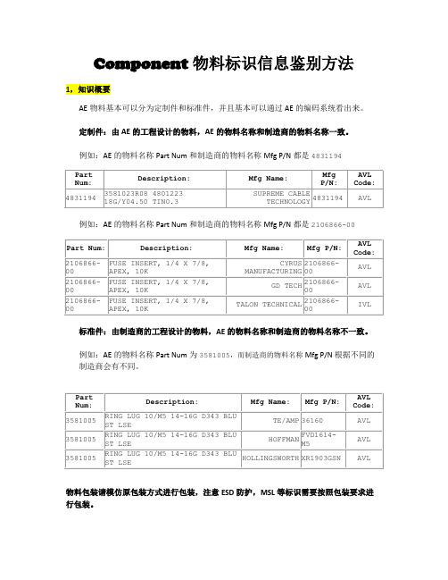
Component物料标识信息鉴别方法1,知识概要AE物料基本可以分为定制件和标准件,并且基本可以通过AE的编码系统看出来。
定制件:由AE的工程设计的物料,AE的物料名称和制造商的物料名称一致。
例如:AE的物料名称Part Num和制造商的物料名称Mfg P/N都是4831194例如:AE的物料名称Part Num和制造商的物料名称Mfg P/N都是2106866-00标准件:由制造商的工程设计的物料,AE的物料名称和制造商的物料名称不一致。
例如:AE的物料名称Part Num为3581005,而制造商的物料名称Mfg P/N根据不同的制造商会有不同。
物料包装请模仿原包装方式进行包装,注意ESD防护,MSL等标识需要按照包装要求进行包装。
2,如何寻找实际物料的MFG,MPN, Date code信息2.1,通过AE的系统获得该物料的MFG,MPN Ptools> component engineer>输入AE的Part number:2.2 对照所获得的MFG,MPN信息表格,进行确认如下流程图2.3 物料信息确认案例案例 1:有些标签90%以上的MFG/MPN信息一样,只是有些字母的区别,基本是对的信息,可以确认MFG/MPN与物料信息表最相近的信息案例 2:有些物料看到AE的PartNum和Mfg P/N是一致的,基本就属于AE的定制件案例 3:有些物料外大包装箱看不到,就看看箱子里面的小包装,然后找标签查看字母数字等和物料信息表接近或一致的信息,如果找到MPN,而看不到MFG,那么信息表里面对应的MFG就是所需的信息。
案例 4:有些物料需要看实物的丝印标识,从而找到信息。
有些MFG信息是简写,主要信息和物料信息表中一样,比如FOX显示在实物丝印上代表FOX ELECTRONICS。
案例 5:有些物料只有MFG,物料标签上只看到AE的Part number,而且是供应商的原始标签,看不到MPN和Date code信息。
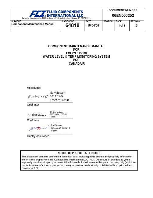
Component Maintenance Manual
Gary Bussett2013.03.0412:29:25 -08'00'Melissa Moisant2013.03.04 17:08:43-08'00'Burt Tanaka2013.03.04 18:10:18-08'00'__________________________________________________________________________________________SUBJECTComponent Maintenance ManualCAGE CODE64818 DATE 10/04/05 SECTION PAGE i of i REVISION BCOMPONENT MAINTENANCE MANUALFORFCI PN 015838WATER LEVEL & TEMP MONITORING SYSTEMFORCANADAIRApprovals:OriginatorContractsQuality AssuranceNOTICE OF PROPRIETARY RIGHTSThis document contains confidential technical data, including trade secrets and propriety informationwhich is the property of Fluid Components International LLC (FCI). Disclosure of this data to you isexpressly conditional upon your assent that its use is limited to use within your company only (and does not include manufacture or processing uses). Any other use is strictly prohibited without prior writtenconsent of FCI.SUBJECTComponent Maintenance Manual CAGE CODE64818 DATE 10/04/05 SECTION PAGE i of ii REVISION B REVISION PAGERev. Description Date -Initial Release 05/15/95A Revised Part Numbers in Figures 1, 3, and 5 02/12/97B Introduction – Changed company name; Figure 3 – Changed Control Unit label;Sect 2.B. Control Unit – Added para. 5 describing differences between -02 and-03; All -Combined sections into single file.10/04/05COMPONENT MAINTENANCE MANUALFCI Document Control Number: 06EN003252 Rev. BWATER LEVEL AND TEMPERATURE MONITORING SYSTEMPART NUMBER: 015838NOTICE OF PROPRIETARY RIGHTSThis document contains confidential technical data, including trade secretsand proprietary information which are the property of Fluid ComponentsIntl (FCI).Disclosure of this data to you is expressly conditioned upon your assentthat its use is limited to use within your company only (and does notinclude manufacture or processing uses). Any other use is strictlyprohibited without the prior written consent of FCI.THIS PAGE INTENTIONALLY LEFT BLANKRECORD OF REVISIONSTHIS PAGE INTENTIONALLY LEFT BLANKRECORD OF TEMPORARY REVISIONSTHIS PAGE INTENTIONALLY LEFT BLANKPART NUMBER 015838SERVICE BULLETIN LISTService Bulletin information is placed in this list when the Service Bulletin is incorporated into this manual.PART NUMBER 015838 THIS PAGE INTENTIONALLY LEFT BLANKLIST OF EFFECTIVE PAGESTHIS PAGE INTENTIONALLY LEFT BLANKTABLE OF CONTENTSPARAGRAPH TITLE PAGE Introduction . . . . . . . . . . . . . . . . . . . . . . . . . . . . . . . . . . . . . . . . . . . . . . . . . . . . . . . 1 Description and Operation . . . . . . . . . . . . . . . . . . . . . . . . . . . . . . . . . . . . . . . . . . . 2 Testing . .. . . . . . . . . . . . . . . . . . . . . . . . . . . . . . . . . . . . . . . . . . . . . . . . . . . . . . . . 7 Cleaning . . . . . . . . . . . . . . . . . . . . . . . . . . . . . . . . . . . . . . . . . . . . . . . . . . . . . . . . . 9 Inspection/Check . . . . . . . . . . . . . . . . . . . . . . . . . . . . . . . . . . . . . . . . . . . . . . . . . . 9 Repair . . . . . . . . . . . . . . . . . . . . . . . . . . . . . . . . . . . . . . . . . . . . . . . . . . . . . . . . . . . 9THIS PAGE INTENTIONALLY LEFT BLANKINTRODUCTION1. GeneralA. This manual provides maintenance instructions for the Model 015838 Water Level andTemperature Monitoring System.B. The information in this abbreviated manual covers the description, operation, testing, cleaning, andinspection of this equipment.C. The instrument is manufactured by Fluid Components International LLC, San Marcos,California (CAGE CODE 64818), for Bombardier Inc. Canadair Group.2. Ordering of PartsOrder of parts are to be directed as follows:Fluid Components Intl1755 La Costa Meadows DriveSan Marcos, California 92069-5187Attention: Customer SalesPhone: (800) 854-1993 or (760) 744-6950 or FAX: (760) 736-62503. Manual RequestsRequests for copies of publications should be directed to the address shown in Paragraph 2.4. Manual RevisionsThis manual will be revised as necessary to reflect current information.DESCRIPTION AND OPERATION1. DescriptionThe Model 015838 Water Level and Temperature Monitoring System monitors the potable water in aircraft potable water tanks. Figure 1 shows the Water Level and Temperature Monitoring System. The system consists of 2 probes that are in physical contact with the potable water, and control circuitry that produces output signals that indicate water level, turn on water heaters, and inhibit pump operations. The system has no moving parts, is lightweight, compact, and reliable. The typical application for the system is to monitor aircraft galley and lavatory potable water tanks. The physical and operational characteristics of the system are listed in Figure 2. Figure 3 shows the outline dimensions of the system for purposes of proper mounting.Water Level and Temperature Monitoring SystemFigure 1Figure 2Outline DimensionsFigure 32. OperationA. ProbeOne probe is screwed into each potable water tank. (A customer supplied O-Ring packing is suggested for use with each probe.) Each probe consists of two polymer strips that contain Resistance Temperature Detectors (RTD)’s. The strips are placed parallel to each other in a sectioned tube. One strip, known as the reference strip, contains two RTD’s. The other strip, known as the active strip, contains five RTD’sThe reference strip contains one RTD for level measurement and one RTD for watertemperature measurement. The active strip contains five RTD’s. All five RTD’s in the active strip are used for level detection. See the probe configuration in Figure 4.When the probe is put in water, the submerged portion of the reference strip is at the watertemperature. The active strip is heated by an electric current and loses some heat to thewater. A Temperature Differential (∆T) exists between the active and reference RTD stripsand a proportional Resistance Differential (∆R) exists that the control unit measures.B. Control UnitThe input to the control unit circuitry is the ΔR. The output of the control unit circuitry isground (enable) or open (disable) signals.The control unit has a two minute warm up period from power up to operation. During thistime the empty level signals, the 1/4 level signals, the 1/2 level signals, the 3/4 level signalsand the full level signals will be enabled one at a time. Then all signals will be disabled. This sequence will repeat every six seconds for the two minute warm up time.The control unit P/N 015840-01 circuitry enables or disables a pump inhibit signal. If thepower has been off for more than 20 ±5 minutes the circuitry will enable the pump inhibitsignal at power up. The pump inhibit signal will be enabled for 15 minutes after power up. If power has been removed and then powered on again within 20 ±5 minutes there will be apump inhibit signal enabled for only the 2 minute warm up period. The pump inhibit signal is also enabled whenever the potable water level is below the empty level on the probe.The control unit P/N 015840-02 is different from the -01 control unit as follows: When amomentary power interrupt occurs, the -02 control unit will bypass the 2 minute warm-upperiod and go directly into displaying the level.The control unit P/N 015480-03 is different from the -02 control unit as follows: The unit has short circuit protection on the signal outputs and reset circuitry to prevent control boxsoftware lock-up.The second RTD in the reference RTD strip along with the control unit circuitry measures the water temperature. For probe #1 (short probe); when the water temperature decreasesbelow 50°F (10°C) the temperature signal is enabled. When the water temperatureincreases above 68°F (20°C) the temperature signal is disabled. For probe #2 (long probe);when the water temperature decreases below 59°F (15°C) the temperature signal is enabled.When the water temperature increases above 95°F (35°C) the temperature signal isdisabled.The control unit detects if there is a probe failure (short or open). If a failure is detected all of the probe level signals are enabled simultaneously for one second, then disabled simultaneously for 5 seconds. The pump inhibit signal is enabled (disabling the pump) and the temperature signal is disabled (removing power to the heater).Probe ConfigurationFigure 4TESTING1. GeneralThe system is easy to troubleshoot due to the simplicity of design. System failures can be as simple to correct as unscrewing a probe and screwing in a new one.2. Test EquipmentPrecision Digital Multi-Meter (DMM)3. Test ProcedureWARNING: ONLY QUALIFIED PERSONNEL SHOULD ATTEMPT TO TEST THIS SYSTEM. THE OPERATOR ASSUMES ALL RESPONSIBILITIES FOR SAFE PRACTICES WHILE TROUBLESHOOTING.A. Verify error: All lights in the aircraft’s potable water monitoring device for probe 1 flash for1 second every 5 seconds. The control unit is not receiving correct signals from probe 1.(1) Check for bent connector pins in control unit enclosure and probe 1 connector (shortprobe for galley potable water tank).(2) Check probe 1 resistances as found on the schematics in Figure 4. The resistancevalues shown are taken at 32°F (0°C). At 68°F (20°C) the resistance is 272±8 ohms.(3) Check the aircraft components that mate with the system for problems. See Figure 5 fora wiring diagram of the system.B. Verify error: All lights in the aircraft’s potable water monitoring device for probe 2 flash for1 second every 5 seconds. The control unit is not receiving correct signals from probe 2.(1) Check for bent connector pins in control unit enclosure and probe 2 connector (longprobe for lavatory potable water tank).(2) Check probe 2 resistances as found on the schematics in Figure 4. The resistancevalues shown are taken at 32°F (0°C). At 68°F (20°C) the resistance is 272±8 ohms.(3) Check the aircraft components that mate with the system for problems. See Figure 5 fora wiring diagram of the system.C. Verify error: No lights lit in the aircraft’s potable water monitoring device during warm upsequence.(1) Check for power to the control unit. See Figure 5. (No lights lit after warm up indicatethat the water level is below the empty level of the probe.)D. Verify error: Lights in the aircraft’s potable water monitoring device indicate incorrect level.(1) Verify the correct probe is in the correct tank. The long 19.86 inch (504 mm) probe isused in the lavatory potable water tank. The short 9.82 inch (248 mm) probe is used inthe galley potable water tank. (The water tanks may not be entirely empty, however if thewater is below the probe the system will register empty.)(2) Remove the probe with the incorrect indication. Remove any ice from the probe.Reinstall the probe.Wiring DiagramFigure 54. ConclusionIf the above conditions have been verified and problems are still being experienced contact the FCI Customer Service Department as shown in paragraph 2 of the introduction.If any units are defective contact FCI Customer Service Department and arrange to have the system unit sent back for repair or replacement.CLEANING1. Cleaning SolutionsA. Isopropyl AlcoholB. Aqueous cleaning / disinfectant solution compatible with potable water containers2. CleaningA. Remove foreign material from the external surfaces of the control unit enclosure with a clothmoist with an aqueous cleaning / disinfectant solution.B. Clean the connectors and pins with isopropyl alcohol and a cotton swab.C. Clean the probe body by dipping it into an aqueous cleaning / disinfectant solution. Do not useorganic solvents on the plastic materials. Dry with a clean cloth.INSPECTION/CHECK1. Control Circuit Enclosure ConditionVisually inspect the control unit enclosure periodically for physical damage. The enclosure should be free of corrosion and cracks.2. Probe ConditionVisually inspect the probe portion of the system for physical damage. The probe should be free of corrosion and cracks.REPAIRThe system is not field repairable other than the removal and replacement of the probes or the control unit enclosure. If the system fails to operate properly return the system unit(s) to FCI at the address in paragraph 2 of the Introduction. There is no need to return all of the system units if just one unit is faulty.THIS PAGE INTENTIONALLY LEFT BLANK。
生产订单更改历史记录(CO02)增强 (PDF 格式)
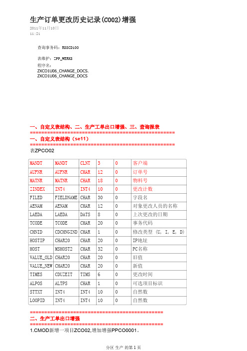
生产订单更改历史记录(CO02)增强2011年11月10日11:21查询事务码:RSSCD100表维护:ZPP_WERKS程序名:ZXCO1U06_CHANGE_DOCS.ZXCO1U06_CHANGE_DOCS一、自定义表结构、二、生产工单出口增强、三、查询报表==================================================一、自定义表结构(se11)==================================================表ZPCO02MANDT MANDT CLNT30客户端AUFNR AUFNR CHAR120订单号MATNR MATNR CHAR180物料号ZINDEX INT4INT4100更改计数FILED FIELDNAME CHAR300字段名AENAM AENAM CHAR120对象更改人员的名称LAEDA LAEDA DATS80上次更改的日期TCODE TCODE CHAR200事务代码CHNID CDCHNGIND CHAR10修改类型(U, I, E, D) HOSTIP CHAR20CHAR200IP地址HOST MSHOST2CHAR320PC名称VALUE_OLD CHAR20CHAR200旧值VALUE_NEW CHAR20CHAR200新值TIMES CDUZEIT TIMS60更改时间ALPOS ALTPS CHAR10可选项目标识STTXT INT4INT4100自然数LOOPID INT4INT4100自然数==============================================二、生产工单出口增强==============================================1.CMOD新增一项目ZCO02,增加增强PPCO0001。
1.CMOD新增一项目ZCO02,增加增强PPCO0001。
Chapter08_模态分析初步2
3.频响函数的测量
1.4 分析系统: (1) 毫伏表、相位计、示波器、滤波器、频率计
(2) 频谱分析仪(模拟式、数字式):HP35665A、 HP3567A、HP3565S
(3) 虚拟设备(PC-Based软件和硬件集成,可视化虚拟分析 仪和显示仪表)
1.5 输出和记录设备: 计算机显示、磁盘、光盘、记录仪、打印机等。
3.频响函数的测量
压电陶瓷(Piezo-Ceramic)激振器:小型、高频(通常可高达 60kHz-180kHz)、推力(Force)小、行程(Stroke)小,位移和波形 (waveform)控制精确(微米级);
电动式(Electrical):频带宽(0-5.5kHz)、能量较大,推力可达吨级, 行程一般可达1至2英寸、位移和波形控制较精确(标准台失真 (distortion)可控制在10%以下),但特大推力困难,出于技术垄断和 军事目的20吨以上推力振动台美国限制对华出口;
电液伺服式(Hydro-Electric Servo):频带窄(0-500 Hz)、能量 大、推力大、行程大;
机械式(Mechanical):频带窄(10-100Hz)、行程一般数毫米、 噪音大、位移和波形控制不精确;
3.频响函数的测量
(2) 冲击激励(Impact Excitation): 力锤(Hammer),适用于小阻尼线性结构。还有夯锤、 落锤、摆式冲击锤、小火箭等;
a(t) A RMS
Time
2.2 自动正弦扫描激励(Auto-Swept Sine Excitation)
Tr
Time
3.频响函数的测量
2.3 随机激励(Random Excitation)
纯随机(Random),应采用汉宁窗(Hanning Window),难免泄漏 (Leakage)
蚌埠2024年08版小学三年级上册第七次英语原题
蚌埠2024年08版小学三年级上册英语原题考试时间:100分钟(总分:120)B卷一、选择题(共计20题,共40分)1、What do you call the study of living things?A. BiologyB. ChemistryC. PhysicsD. Geography2、What do we call the period before a baby is born?A. PregnancyB. ChildhoodC. AdolescenceD. Adulthood3、选择题:What do we call a place where we can buy books?A. LibraryB. BookstoreC. MallD. Museum4、What is the main component of stars?A. WaterB. HydrogenC. OxygenD. Carbon5、What do bees make?A. HoneyB. MilkC. BreadD. Cheese6、What is the capital of Portugal?A. LisbonB. PortoC. MadridD. Barcelona7、What is a black hole?A. A dark starB. A collapsed star with strong gravityC. A type of asteroidD. A planet8、选择题:How many sides does a square have?A. 3B. 4C. 5D. 69、Which day comes after Monday?A. SundayB. TuesdayC. WednesdayD. Thursday10、What is the largest land animal?A. LionB. ElephantC. HippopotamusD. Rhino11、How many colors are in the flag of the USA?A. TwoB. ThreeC. FourD. Five12、What do we call a young rabbit?A. KitB. PupC. CubD. Chick13、Which season comes after winter?A. FallB. SpringC. SummerD. Autumn14、How many sides does a triangle have?A. 3B. 4C. 5D. 615、How many players are there on a soccer team?A. 9B. 10C. 11D. 1216、What is the main ingredient in pancake batter?A. FlourB. SugarC. EggsD. Water17、What is the name of the largest land animal?A. ElephantB. RhinocerosC. GiraffeD. Hippopotamus18、What is the primary color of the ocean?A. BlueB. GreenC. RedD. Yellow19、What do we call the process of converting a solid directly into a gas?A. MeltingB. EvaporationC. SublimationD. Freezing20、选择题:What is 30 ÷ 3?A. 5B. 7C. 9D. 10二、听力题(共计20题,共40分)A goldfish is a popular _______.2、听力题:The main gas produced during respiration is _______.3、听力题:They are ___ (running/walking) in the race.4、听力题:The teacher is _____ (kind/strict).5、听力题:A __________ is a low area that collects water.6、听力填空题:I love going to the theater to watch __________.7、听力题:The law of conservation of mass means that mass is neither created nor ______.8、听力题:The city of Damascus is the capital of _______.9、听力题:In chemistry, a solvent is usually present in a _____ (greater amount) than the solute.10、听力题:My sister is learning how to ____ (swim) this summer.11、听力题:The flowers bloom in _____ (spring/fall).12、听力题:My sister has a knack for ____ (writing).13、听力题:Many different cultures can be found in _______.14、听力题:Combustion is a chemical reaction that involves ______.15、听力题:A chemical reaction that produces light and heat is called a ______ reaction.__________ are used in the production of rubber.17、听力题:The Earth's surface is constantly changing through the processes of ______ and erosion.18、听力题:The gas that is commonly used in balloons is ______.19、听力题:The symbol for platinum is _____.20、听力题:A __________ is formed through the interaction of biotic and abiotic factors.三、填空题(共计20题,共10分)1、填空题:I like to play with my toy ________ (玩具名称) in the yard.2、填空题:We saw a ______ climbing a tree.3、填空题:I enjoy making ______ (手工艺品) for my friends.4、填空题:The __________ (多样性) of plants and animals is important.5、填空题:My friend has a pet ______ (仓鼠) that loves to run.6、填空题:I like to color pictures of _____.7、填空题:The city of Venice is known for its ________ (运河).8、填空题:The ________ is a tiny creature that can sting.9、填空题:The _______ (猴子) can swing from branch to branch.A __________ (碳足迹) measures the environmental impact of chemical processes.11、填空题:I saw a _______ (小动物) at the nature reserve.12、填空题:This __________ (玩具名) is made of __________ (材料).13、填空题:The kangaroo is a unique _______ (澳洲) animal.14、填空题:I have a toy _______ that can make me smile.15、填空题:My brother is excited about ____.16、填空题:Planting flowers can attract ______ (蝴蝶) to your garden.17、填空题:The ancient Romans celebrated ______ (节日) in honor of their gods.18、填空题:The __________ (旅行计划) includes many destinations.19、填空题:A ________ (观赏花) can brighten any space.20、填空题:The ______ (金色的蟾蜍) is often found near water.。
轮机专业component模块

第五章 Components 的使用5.1. 简介设备、部件、管系、电缆、通风以及铁舾装件是舾装生产数字化设计中重要组成部分。
通过向设计完成的船体数字空间中调用设备及铁舾装件,按设计规范进行布置,再通过在同一场景下按系统设计与规范要求进行的管、风、电的布放,将完成船舶舾装的数字化放样设计。
但是,几何元素的布置并不能满足企业对于生产信息提取、组织、集配的需要。
在大的空间中设备与各种舾装件的布置许多是基于约束条件或基于特征映射的装配过程。
上述这些信息,必须通过信息处理器加以整理,进入Tribon 系统。
Tribon 系统为用户提供了Components 信息处理,它通过编码的形式,由用户将各类相关的信息(如形状、标准说明、重量、连接信息等)加以整理输入到计算机中供系统与用户的查询、调用,使数字化设计的虚拟船舶成为具有PIM(Product Information Model)产品信息模型。
5.2. Components 的启动在Windows 下点取:开始→程序→Tribon M3→Outfitting →Components在文件管理器中包含了管子、电气、通风、舱室、基座、电缆,铁舾、绝缘、紧固件、家具,梯子、构件、其它。
轮机专业主要使用的有Piping 、Venilation 、Insulation 3个分类。
每个分类下又分成了更多的子类。
下面是以piping 为例:Piping包括:管路连接件、法兰、阀、连接件、管材、管路附件、一般附件。
下面我们完全打开一个目录来了解一下components的结构:其中piping是主类,couplings是piping的类,2-way couplings是couplings的子类,straight coupling是2-way couplings的族。
CB53-80F是straight coupling的1个成组的项,图标是下面还有一个具体的成员CB53-80F-1,CB53-80F-1就是我们在建模是选择的Components名称。
MORNSUN LS08-13BxxSS系列AC DC电源说明书
8W,DIY AC/DC converterRoHSFEATURES●Ultra-wide 85-305VAC and 100-430VDC input voltage range ●Accepts AC or DC input (dual-use of same terminal)●Operating ambient temperature range:-40℃~+85℃●Multi-application available,flexible layout ●High power density,high reliability●Low power consumption,green power●Output short circuit,over-current protection●Designed to meet IEC/EN/UL62368safety standards (Pending)●Designed to meet IEC/EN/UL60335safety standardsLS08-13BxxSS series is one of Mornsun’s highly efficient green power AC-DC Converter series.They feature ultra-wide wide input rangeaccepting either AC or DC voltage,high efficiency,low power consumption and CLASS II reinforced insulation.All models are particularly suitable for industrial control,electric power,instrumentation and smart home applications which don’t have high requirement for dimension.A variety of EMC external circuits meet the needs of multiple industries.Input SpecificationsItemOperating Conditions Min.Typ.Max.Unit Input Voltage Range AC input 85--305V AC DC input100--430VDC Input Frequency 47--63HzInput Current 115V AC ----0.3A 277V AC ----0.15Inrush Current115V AC --15--277V AC--30--Recommended External Input Fuse 1A,slow-blow,requiredHot PlugUnavailableOutput SpecificationsItemOperating Conditions Min.Typ.Max.UnitOutput Voltage Accuracy 0%-100%load 3.3V output --±1.5±3%Other output--±1±2Line Regulation Rated load --±0.5±1Load Regulation 0%-100%load--±1±1.5Ripple &Noise *20MHz bandwidth (peak-to-peak value)--80150mV Temperature Coefficient --±0.02--%/°C Short Circuit Protection Hiccup,continuous,self-recoveryOver-current Protection ≥110%Io,self-recoveryMinimum Load----%Note:*The “parallel cable”method is used for ripple and noise test,please refer to AC-DC Converter Application Notes for specific information.Selection GuideCertificationPart No.Output PowerNominal Output Voltage and Current (Vo/Io)Efficiency at 230V AC(%)Typ.Capacitive Load(µF)Max.CE/UL/CB (Pending)LS08-13B03SS 5.28W3.3V/1600mA 701500LS08-13B05SS8W 5V/1600mA 741500LS08-13B09SS 9V/880mA 751000LS08-13B12SS 12V/670mA 76680LS08-13B15SS 15V/530mV 77470LS08-13B24SS24V/330mA79330General SpecificationsItem Operating Conditions Min.Typ.Max.UnitIsolation Test Input-output Electric Strength Test for1min.,(leakage current<5mA)3000----VACOperating Temperature-40--+85℃Storage Temperature-40--+105Storage Humidity----95%RHPower Derating -40℃~-25℃ 2.67----%/℃+55℃~+85℃ 2.5----85V AC-100VAC1----277V AC-305V AC0.54----Safety Standard IEC/EN/UL62368,IEC/EN/UL60335 Safety Certification IEC/EN/UL62368(Pending) Safety CLASS CLASS IIMTBF MIL-HDBK-217F@25°C>300,000h Mechanical SpecificationsCase Material44.50x24.00x15.00mmWeight11g(Typ.)Cooling method Free air convectionElectromagnetic Compatibility(EMC)Emissions CECISPR32/EN55032CLASS A(Recommended circuit1,4)CISPR32/EN55032CLASS B(Recommended circuit2,3) RECISPR32/EN55032CLASS A(Recommended circuit1,4)CISPR32/EN55032CLASS B(Recommended circuit2,3)Immunity ESD IEC/EN61000-4-2Contact±6KV Perf.Criteria B RS IEC/EN61000-4-310V/m perf.Criteria AEFTIEC/EN61000-4-4±2KV(Recommended circuit1,2)perf.Criteria BIEC/EN61000-4-4±4KV(Recommended circuit3,4)perf.Criteria B SurgeIEC/EN61000-4-5line to line±1KV(Recommended circuit1,2)perf.Criteria BIEC/EN61000-4-5line to line±2KV(Recommended circuit3,4)IEC/EN61000-4-5line to line±4KV(Recommended circuit4)perf.Criteria B CS IEC/EN61000-4-610Vr.m.s perf.Criteria A Voltage dips,shortinterruptions and voltagevariations immunityIEC/EN61000-4-110%,70%perf.Criteria BProduct Characteristic CurveNote:①With an AC input between85-100VAC/277-305VAC and a DC input between100-120VDC/390-430VDC,the output power must be derated as per temperature derating curves;②This product is suitable for applications using natural air cooling;for applications in closed environment please consult factory or one of our FAE.Additional Circuits Design ReferenceLS series additional circuits design referenceLS08series additional components selection guidePart No.FUSE(required)C1required)C2(required)L1(required)C3(required )C4CY1(required )LS08-13B03SS 1A/300V22µF/450V470µF/16V(solid-state capacitor) 4.7µH 150µF/35V 0.1µF/50V1.0nF/400V ACLS08-13B05SS LS08-13B09SS 220µF/16V(solid-state capacitor)100µF/35V LS08-13B12SS LS08-13B15SS 470uF/35V 47µF/35VLS08-13B24SS220uF/35VNote:1.C1:input capacitors,C2:output storage capacitors,they must be connected externally.2.We recommend using an electrolytic capacitor with high frequency and low ESR rating for C3(refer to manufacture’s datasheet).Combined with C2,L1,they form a pi-type filter circuit.Choose a capacitor voltage rating with at least 20%margin,in other words not exceeding 80%.C4is a ceramic capacitor,used for filtering high frequency noise.A suppressor diode (TVS)is a recommended to protect the application in case of a converter failure and specification should be 1.2times of the output voltage.Immunity design circuits for referenceEmissions design circuits for referenceCLASS ⅢCLASS ⅣCLASS ACLASS BEnvironmental Application EMC SolutionLS series environmental application EMC solution selection tableRecommendedcircuit Application environmental Typical industryInput voltagerangeEnvironment temperature Emissions Immunity 1Basic applicationNone85~305V AC -40℃~+85℃CLASS A CLASS Ⅲ2Indoor civil environment Smart home/Home appliances(2Y)-25℃~+55℃CLASS BCLASS ⅢIndoor general environment Intelligent building/Intelligentagriculture 3Indoor industrial environment Manufacturing workshop -25℃~+55℃CLASS B CLASS Ⅳ4Outdoor general environmentITS/Video monitoring/Charging point/Communication/Securityand protection-40℃~+85℃CLASS ACLASS ⅣOutdoor harsh environmentOn-line power meter Communication base station-40℃~+85℃CLASS A>CLASS ⅣSurge:line to ground ±4KV EFT:CLASS ⅣElectromagnetic Compatibility Solution--Recommended Circuit1.Recommended circuit 1——Basic applicationrecommended circuit 1Application environmentalAmbient temperature rangeImmunity CLASSEmissions CLASSBasic application-40℃~+85℃CLASS ⅢCLASS AComponentRecommended valueR112Ω/3W LDM4.7mH2.Recommended circuit 2——Indoor civil /Universal system recommended circuits for general environmentRecommended circuit 2Application environmentalAmbient temperature rangeImmunity CLASSEmissions CLASS Indoor civil /general -25℃~+55℃CLASS ⅢCLASS BComponentRecommended valueR112Ω/3W CY1(CY2) 1.0nF/400V ACLCM 3.5mH LDM 0.33mH CX0.1µF/310VAC FUSE (required)1A/300V ,slow-blowNote:In the home appliance application environment,the two Y capacitors of the primary and secondary need to be externally connected (CY1/CY2,value at 2.2nF/400VAC),which can meet the EN60335certification.In other industries,only one Y capacitor is needed.3.Recommended circuit 3——Universal system recommended circuits for indoor industrial environmentRecommended circuit 3Application environmental Ambienttemperature rangeImmunity CLASSEmissions CLASSIndoor industrial-25℃~+55℃CLASS ⅣCLASS BComponentRecommended valueMOV S14K350C1450V/22uF CY1 2.2nF/400V AC CX 0.1µF/310V ACLCM 3.5mH LDM 0.33mH R112Ω/3WFUSE (required)2A/300V ,slow-blow4.Recommended circuit 4——Universal system recommended circuits for outdoor general/harsh environmentRecommended circuit 4Application environmental Ambienttemperature rangeImmunity CLASSEmissions CLASSOutdoor general environment-40℃~+85℃CLASS ⅣCLASS AComponentRecommended valueMOV S14K350C1450V/22uF LDM 4.7mH R112Ω/3WFUSE (required)2A/300V ,slow-blowApplication environmental Ambient temperaturerangeImmunity CLASS EmissionsCLASSOutdoor harsh environment -40℃~+85℃>CLASSⅣSurge:line to ground±4KVEFT:CLASSⅣCLASS AComponent Recommended valueMOV S20K350C1450V/33uF(Surge protection priority)LDM 4.7mHR133Ω/5WFUSE(required) 6.3A/300V,slow-blow5.For additional information please refer to application notes on . LS08-13BxxSS Dimensions and Recommended LayoutNote:1.For additional information on Product Packaging please refer to .Packaging bag number:58220032;2.External electrolytic capacitors are required to modules,more details refer to typical applications;3.This part is open frame,at least6.4mm safety distance between the primary and secondary external components of the module isneeded to meet the safety requirement;4.Unless otherwise specified,parameters in this datasheet were measured under the conditions of Ta=25℃,humidity<75%,nominal inputvoltage(115V and230V)and rated output load;5.In order to improve the efficiency at light load,there will be audible noise generated,but it does not affect product performance andreliability;6.Module required dispensing fixed after assembled;7.All index testing methods in this datasheet are based on our company corporate standards;8.We can provide product customization service,please contact our technicians directly for specific information;9.Products are related to laws and regulations:see"Features"and"EMC";10.Our products shall be classified according to ISO14001and related environmental laws and regulations,and shall be handled byqualified units.Mornsun Guangzhou Science&Technology Co.,Ltd.Address:No.5,Kehui St.1,Kehui Development Center,Science Ave.,Guangzhou Science City,Huangpu District,Guangzhou,P.R.China Tel:86-20-38601850Fax:86-20-38601272E-mail:***************。
uvm知识点总结

uvm知识点总结UVM 架构UVM 的架构包括以下几个重要部分:1. UVM 库 (UVM Library): UVM 库是一个可复用的验证组件集合,包含了多个验证类,如uvm_component、uvm_object、uvm_sequence 等,这些类组成了 UVM 框架。
2. UVM Testbench: UVM Testbench 是一个验证环境框架,它是基于 UVM 库构建起来的,用于创建验证环境、生成测试用例、进行仿真等。
3. UVM Test: UVM Test 是一个测试用例,主要由 UVM sequence 和 UVM 配置对象构成,它是用来验证被测试设计的功能是否正确。
4. UVM Agent: UVM Agent 是一个验证组件,是用于连接被测试设计和验证环境的中间层;它包括了 driver、monitor、sequence、sequencer 等。
基本概念UVM 中的一些基本概念包括以下内容:1. UVM Component: UVM 组件是 UVM 测试环境中的基本单元,用于组织和管理验证环境中的各种功能。
UVM 组件包括了 uvm_component、uvm_object、uvm_sequence 等。
2. UVM Object: UVM 对象是 UVM 中的一个基本概念,它是 uvm_component、uvm_sequence 和 uvm_transaction 的基类,用于实现类似于面向对象编程的功能。
3. UVM Phase: UVM 通过阶段 (Phase) 来管理验证环境的初始化、运行和结束等过程。
UVM 提供了一系列的任务来进行阶段的管理,如 uvm_phase、uvm_sequence、uvm_objection 等。
4. UVM Transaction: UVM 事务是指在验证中进行的交互过程,包括了数据传输、信号传递、命令执行等;UVM 提供了 uvm_transaction 类来实现事务级建模。
基于MODBUS协议和IEC_61850协议的变电站通信电源监控研究
电源与节能技术IEC 61850协议的变电站通信电源监控研究张焱(国网河北省电力有限公司超高压分公司,河北现有的变电站电源大多互相独立,导致系统间的通信协议互不兼容,实现对变电站电源的智能化监控,提出一种基于MODBUS协议和IEC 61850协议标准化变电站通信电源系统数据,并通过软件转换模块实现不同通信协议之间的转换,实时监该变电站电源监控系统能实现充电机与电池管理系统、有效解决现有电源监控系统数据共享难、监控信息不完整的问题。
变电站通信电源;在线监控;MODBUS协议;IEC 61850Research on Substation Communication Power Supply Monitoring Based on MODBUSProtocol and IEC 61850 ProtocolZHANG Yan(State Grid Hebei Electric Power Co., Ltd., Ultra High Voltage Branch, Shijiazhuangsubstation power supplies are充数据。
若扩充数据后的逻辑节点满足要求,则选取标准中的节点,对数据进行判断。
如果数据满足要求,则添加标准中的数据,否则添加新数据[4-5]。
若节点本身不满足要求,则需要定义新的逻辑节点,并按照先前的判断标准判断数据是否满足要求。
由于变电站电源种类丰富,为提高电源监控的普适性,文章在监控方案中添加了逆变电源、蓄电池、交流电源、直流电源以及不间断电源(Uninterruptable Power Supply ,UPS )的监控需求。
确定好监控需求后,对逻辑节点进行确认。
考虑电源监控需求,逻辑节点分为逻辑节点0、物理逻辑节点、交/直流母线、逆变器、交/直流进线、充电模块、单体电池以及蓄电池。
同时,将相似的逻辑节点组合在一起,构成逻辑设备。
为实现多种电源的在线监控,确保逻辑设备模型的清晰度,逻辑节点应涵盖所有功能需求,且同一功能的参数应集中在一个逻辑节点[6-7]。
三星贴片电容规格书08
�
America sales office
Irvine Office 92612 3345 Michelson Drive, Suite 350,Irvine, CA Te l:1- 949 - 797- 8047 E-mail:sh386.kim@
MULTILAYER CERAMIC CAPACITORS
65
Quality System Certification List
ISO / TS 16949 ISO 9001 (Product) TL 9000 (Product) ISO 14001 OSHAS 18001
Table 1:Certification list of Samsung Factory
January 2008
Passive components Sales Office
�
Head Office
206, Cheomdansaneop Road, Youngtong-gu, Suwon, Kyonggi Province 443-743, Korea Europe Te l: +82- 31- 210 - 6803 E-mail:wesley.roh@ America Te l: +82- 31- 210 - 6794 E-mail:randy.kim@ Asia Te l: +82 - 31- 210 - 5348 E-mail:koogi@ Domestic Te l: +82- 31- 210 - 3757 E-mail:southjoy@
�
Domestic Distributors
KORCHIP INC #219 - 8 Gasan - dong, Gumchun - gu, Seoul, Korea Te l: +82 - 2 - 838 - 5588 E-mail:hjh0064@ CHUNG HAN #16-96 Hangang - lo 3, Youngsan - Gu, Seoul, Korea Te l: +82-2-718-3322 E-mail:bu1230choi@ SAMT Daekyung Bldg.,Daechi-Dong, Gangnam- Gu, Seoul, Korea Te l: +82- 2- 3458- 9000 E-mail:info@ CHUNGMAC #53-5 Wonhyolo3 Youngsan- gu, Seoul, Korea Te l: +82- 2- 716 - 6428~9 E-mail:webmaster@anycam.co.kr APEXINT , Room #905. C- dong Woorimlion s, Valley 371-28, Gasan-dong, Guemcheon-Gu, Seoul, Korea Te l: +82- 2- 2026- 2610(2) E-mail:info@apexint.co.kr
IPC-7351B & PCBL Land Pattern Naming Convention

I P C-7351B N a m i n g C o n v e n t i o n f o r S t a n d a r d S M T L a n d P a t t e r n sSurface Mount Land PatternsComponent, Category Land Pattern Name Ball Grid Array’s...............................BGA + Pin Qty + C or N + Pitch P + Ball Columns X Ball Rows _ Body Length X Body Width X Height BGA w/Dual Pitch.BGA + Pin Qty + C or N + Col Pitch X Row Pitch P + Ball Columns X Ball Rows _ Body Length X Body Width X Height BGA w/Staggered Pins..................BGAS + Pin Qty + C or N + Pitch P + Ball Columns X Ball Rows _ Body Length X Body Width X Height BGA Note: The C or N = Collapsing or Non-collapsing BallsCapacitors, Chip, Array, Concave..........................................................CAPCAV + Pitch P + Body Length X Body Width X Height - Pin Qty Capacitors, Chip, Array, Flat..................................................................CAPCAF + Pitch P + Body Length X Body Width X Height - Pin Qty Capacitors, Chip, Non-polarized.................................................................................................CAPC + Body Length + Body Width X Height Capacitors, Chip, Polarized.....................................................................................................CAPCP + Body Length + Body Width X Height Capacitors, Chip, Wire Rectangle........................................................................................CAPCWR + Body Length + Body Width X Height Capacitors, Molded, Non-polarized...........................................................................................CAPM + Body Length + Body Width X Height Capacitors, Molded, Polarized.................................................................................................CAPMP + Body Length + Body Width X Height Capacitors, Aluminum Electrolytic ............................................................................................................CAPAE + Base Body Size X Height Ceramic Flat Packages.....................................................................................................CFP127P + Lead Span Nominal X Height - Pin Qty Column Grid Array’s.....................................................CGA + Pitch P + Number of Pin Columns X Number of Pin Rows X Height - Pin Qty Crystals (2 leads)........................................................................................................................XTAL + Body Length X Body Width X Height Dual Flat No-lead..........................................................................................................DFN + Body Length X Body Width X Height – Pin Qty Diodes, Chip................................................................................................................................DIOC + Body Length + Body Width X Height Diodes, Molded...........................................................................................................................DIOM + Body Length + Body Width X Height Diodes, MELF................................................................................................................................DIOMELF + Body Length + Body Diameter Fuses, Molded............................................................................................................................FUSM + Body Length + Body Width X Height Inductors, Chip.............................................................................................................................INDC + Body Length + Body Width X Height Inductors, Molded........................................................................................................................INDM + Body Length + Body Width X Height Inductors, Precision Wire Wound................................................................................................INDP + Body Length + Body Width X Height Inductors, Chip, Array, Concave..............................................................INDCAV + Pitch P + Body Length X Body Width X Height - Pin Qty Inductors, Chip, Array, Flat......................................................................INDCAF + Pitch P + Body Length X Body Width X Height - Pin Qty Land Grid Array, Round Lead............................LGA + Pin Qty - Pitch P + Pin Columns X Pin Rows _ Body Length X Body Width X Height Land Grid Array, Square Lead........................LGAS + Pin Qty - Pitch P + Pin Columns X Pin Rows _ Body Length X Body Width X Height LED’s, Molded............................................................................................................................LEDM + Body Length + Body Width X Height Oscillators, Side Concave........................................................................OSCSC + Pitch P + Body Length X Body Width X Height - Pin Qty Oscillators, J-Lead.......................................................................................OSCJ + Pitch P + Body Length X Body Width X Height - Pin Qty Oscillators, L-Bend Lead.............................................................................OSCL + Pitch P + Body Length X Body Width X Height - Pin Qty Oscillators, Corner Concave....................................................................................................OSCCC + Body Length X Body Width X Height Plastic Leaded Chip Carriers..................................................PLCC + Pitch P + Lead Span L1 X Lead Span L2 Nominal X Height - Pin Qty Plastic Leaded Chip Carrier Sockets Square.......................PLCCS + Pitch P + Lead Span L1 X Lead Span L2 Nominal X Height - Pin Qty Quad Flat Packages..................................................................QFP + Pitch P + Lead Span L1 X Lead Span L2 Nominal X Height - Pin Qty Ceramic Quad Flat Packages.................................................CQFP + Pitch P + Lead Span L1 X Lead Span L2 Nominal X Height - Pin Qty Quad Flat No-lead................................................................QFN + Pitch P + Body Width X Body Length X Height - Pin Qty + Thermal Pad Pull-back Quad Flat No-lead..............................................PQFN + Pitch P + Body Width X Body Length X Height - Pin Qty + Thermal Pad Quad Leadless Ceramic Chip Carriers..........................................................LCC + Pitch P + Body Width X Body Length X Height - Pin Qty Quad Leadless Ceramic Chip Carriers (Pin 1 on Side)...............................LCCS + Pitch P + Body Width X Body Length X Height - Pin Qty Resistors, Chip...........................................................................................................................RESC + Body Length + Body Width X Height Resistors, Molded......................................................................................................................RESM + Body Length + Body Width X Height Resistors, MELF...........................................................................................................................RESMELF + Body Length + Body Diameter Resistors, Chip, Array, Concave............................................................RESCAV + Pitch P + Body Length X Body Width X Height - Pin Qty Resistors, Chip, Array, Convex, E-Version (Even Pin Size)...............RESCAXE + Pitch P + Body Length X Body Width X Height - Pin Qty Resistors, Chip, Array, Convex, S-Version (Side Pins Diff)................RESCAXS + Pitch P + Body Length X Body Width X Height - Pin Qty Resistors, Chip, Array, Flat.....................................................................RESCAF + Pitch P + Body Length X Body Width X Height - Pin Qty Small Outline Diodes, Flat Lead...................................................................................SODFL + Lead Span Nominal + Body Width X Height Small Outline IC, J-Leaded........................................................................................SOJ + Pitch P +Lead Span Nominal X Height - Pin Qty Small Outline Integrated Circuit, (50 mil Pitch SOIC)......................................................SOIC127P +Lead Span Nominal X Height - Pin Qty Small Outline Packages............................................................................................SOP + Pitch P +Lead Span Nominal X Height - Pin Qty Small Outline No-lead...........................................................SON + Pitch P + Body Width X Body Length X Height - Pin Qty + Thermal Pad Pull-back Small Outline No-lead.........................................PSON + Pitch P + Body Width X Body Length X Height - Pin Qty + Thermal Pad Small Outline Transistors, Flat Lead....................................................................SOTFL + Pitch P + Lead Span Nominal X Height - Pin Qty SOD (Example: SOD3717X135 = JEDEC SOD123)........................................................SOD + Lead Span Nominal + Body Width X Height SOT89 (JEDEC Standard Package).......................................................................................................................................................SOT89 SOT143 & SOT343 (JEDEC Standard Package)..............................................................................................................SOT143 & SOT343 SOT143 & SOT343 Reverse (JEDEC Standard Package)...........................................................................................SOT143R & SOT343R SOT23 & SOT223 Packages (Example: SOT230P700X180-4)...............................SOT + Pitch P + Lead Span Nominal X Height - Pin Qty TO (Generic DPAK - Example: TO228P970X238-3).................................................................TO + Pitch P + Lead Span X Height - Pin QtyI P C-7351B L a n d P a t t e r n N a m i n g C o n v e n t i o n N o t e s•All dimensions are in Metric Units•All Lead Span and Height numbers go two places past the decimal point and “include” trailing Zeros•All Lead Span and Body Sizes go two place before the decimal point and “remove” leading Zeros•All Chip Component Body Sizes are one place to each side of the decimal point•Pitch Values are two places to the right & left of decimal point with no leading Zeros but include trailing zeros N a m i n g C o n v e n t i o n S p e c i a l C h a r a c t e r U s e f o r L a n d P a t t e r n sThe _ (underscore) is the separator between pin Qty in Hidden & Deleted pin componentsThe – (dash) is used to separate the pin qty.The X (capital letter X) is used instead of the word “by” to separate two numbers such as height X width like “Quad Packages”.P C B L i b r a r i e s S u f f i x N a m i n g C o n v e n t i o n f o r L a n d P a t t e r n sCommon SMT Land Pattern to Describe Environment Use (This is the last character in every name)Note: This excludes the BGA component family as they only come in the Nominal Environment Condition •M.................Most Material Condition (Level A)•N..................Nominal Material Condition (Level B)•L.................Least Material Condition (Level C)Alternate Components that do not follow the JEDEC, EIA or IEC Standard•A..................Alternate Component (used primarily for SOP & QFP when Component Tolerance or Height is different) •B..................Second Alternate ComponentReverse Pin Order•-20RN..........20 pin part, Reverse Pin Order, Nominal EnvironmentHidden Pins•-20_24N......20 pin part in a 24 pin package. The pins are numbered 1 – 24 the hidden pins are skipped. The schematic symbol displays up to 24 pins.Deleted Pins•-24_20N......20 pin part in a 24 pin package. The pins are numbered 1 – 20. The schematic symbol displays 20 pins. JEDEC and EIA Standard parts that have several alternate packages•AA, AB, AC.JEDEC or EIA Component IdentifierGENERAL SUFFIXES_HS.........................HS = Land Pattern with Heat Sink attachment requiring additional holes or padsExample: TO254P1055X160_HS-6N_BEC......................BEC = Base, Emitter and Collector (Pin assignments used for three pin Transistors)Example: SOT95P280X160_BEC-3N_SGD......................SGD = Source, Gate and Drain (Pin assignments used for three pin Transistors)Example: SOT95P280X160_SGD-3N_213........................213 = Alternate pin assignments used for three pin TransistorsExample: SOT95P280X160_213-3NP C B L i b r a r i e s N a m i n g C o n v e n t i o n f o r N o n-S t a n d a r d S M T L a n d P a t t e r n s Surface Mount Land PatternsComponent, Category Land Pattern Name Amplifiers....................................................................................................................................................AMP_ Mfr.’s Part Number Batteries......................................................................................................................................................BAT_ Mfr.’s Part Number Capacitors, Variable..................................................................................................................................CAPV_Mfr.’s Part Number Capacitors, Chip, Array, Concave (Pins on 2 or 4 sides)..............................................................CAPCAV_Mfr Series No. - Pin Qty Capacitors, Chip, Array, Flat (Pins on 2 sides)..............................................................................CAPCAF_Mfr Series No. - Pin Qty Capacitors, Miscellaneous............................................................................................................................CAP_Mfr.’s Part Number Crystals......................................................................................................................................................XTAL_Mfr.’s Part Number Diodes, Miscellaneous...................................................................................................................................DIO_Mfr.’s Part Number Diodes, Bridge Rectifiers............................................................................................................................DIOB_Mfr.’s Part Number Ferrite Beads..................................................................................................................................................FB_Mfr.’s Part Number Fiducials......................................................................................................................................FID + Pad Size X Solder Mask Size Filters..............................................................................................................................................................FIL_Mfr.’s Part Number Fuses..........................................................................................................................................................FUSE_Mfr.’s Part Number Fuse, Resettable.....................................................................................................................................FUSER_Mfr.’s Part Number Inductors, Miscellaneous...............................................................................................................................IND_Mfr.’s Part Number Inductors, Chip, Array, Concave (Pins on 2 or 4 sides)..................................................................INDCAV_Mfr Series No. - Pin Qty Inductors, Chip, Array, Flat (Pins on 2 sides).................................................................................INDCAF_Mfr Series No. - Pin Qty Keypad.................................................................................................................................................KEYPAD_Mfr.’s Part Number LEDS............................................................................................................................................................LED_Mfr.’s Part Number LEDS, Chip...................................................................................................................................................LED_Mfr.’s Part Number Liquid Crystal Display...................................................................................................................................LCD_Mfr.’s Part Number Microphones..................................................................................................................................................MIC_Mfr.’s Part Number Opto Isolators............................................................................................................................................OPTO_Mfr.’s Part Number Oscillators......................................................................................................................................OSC_Mfr.’s Part Number - Pin Qty Quad Flat Packages w/Bumper Corners, Pin 1 Side.............BQFP + Pitch P + Lead Span L1 X Lead Span L2 Nominal X Height - Pin Qty Quad Flat Packages w/Bumper Corners, 1 Center..............BQFPC + Pitch P + Lead Span L1 X Lead Span L2 Nominal X Height - Pin Qty Resistors, Chip, Array, Concave (Pins on 2 or 4 sides).................................................................RESCAV_Mfr Series No. - Pin Qty Resistors, Chip, Array, Convex Type E (Pins on 2 sides)...........................................................RESCAXE_Mfr Series No. - Pin Qty Resistors, Chip, Array, Convex Type S (Pins on 2 sides)...........................................................RESCAXS_Mfr Series No. - Pin Qty Resistors, Chip, Array, Flat (Pins on 2 sides)................................................................................RESCAF_Mfr Series No. - Pin Qty Relays.....................................................................................................................................................RELAY_Mfr.’s Part Number Speakers....................................................................................................................................................SPKR_Mfr’s Part Number Switches........................................................................................................................................................SW_Mfr.’s Part Number Test Points, Round......................TP + Pad Size (1 place left of decimal and 2 places right of decimal, Example TP100 = 1.00mm) Test Points, Square...............................................................TPS + Pad Size (1 place left of decimal and 2 places right of decimal) Test Points, Rectangle....................................TP + Pad Length X Pad Width (1 place left of decimal and 2 places right of decimal) Thermistors.............................................................................................................................................THERM_Mfr.’s Part Number Transceivers.............................................................................................................................................XCVR_ Mfr.’s Part Number Transducers (IRDA’s)................................................................................................................................XDCR_Mfr.’s Part Number Transient Voltage S_Mfr.’s Part Number Transient Voltage Suppressors, SP_Mfr.’s Part Number Transistor Outlines, Custom....................................................................................................................TRANS_Mfr.’s Part Number Transformers.............................................................................................................................................XFMR_Mfr.’s Part Number Trimmers & Potentiometers........................................................................................................................TRIM_Mfr.’s Part Number Tuners.....................................................................................................................................................TUNER_Mfr.’s Part Number Varistors.......................................................................................................................................................VAR_Mfr.’s Part Number Voltage Controlled Oscillators.....................................................................................................................VCO_Mfr.’s Part Number Voltage Regulators, Custom......................................................................................................................VREG_Mfr.’s Part NumberI P C-7251N a m i n g C o n v e n t i o n f o r T h r o u g h-H o l e L a n d P a t t e r n sThe land pattern naming convention uses component dimensions to derive the land pattern name.The first 3 – 6 characters in the land pattern name describe the component family.The first number in the land pattern name refers to the Lead Spacing or hole to hole location to insert the component lead.All numbers that follow the Lead Spacing are component dimensions.These characters are used as component body identifiers that precede the value and this is the priority order of the component body identifiers –P = Pitch for components with more than two leadsW = Maximum Lead Width (or Component Lead Diameter)L = Body Length for horizontal mountingD = Body Diameter for round component bodyT = Body Thickness for rectangular component bodyH = Height for vertically mounted componentsQ = Pin Quantity for components with more than two leadsR = Number of Rows for connectorsA, B & C = the fabrication complexity level as defined in the IPC-2221 and IPC-2222Notes:All component body values are in millimeters and go two places to the right of the decimal point and no leading zeros.All Complexity Levels used in the examples are “B”.Component, Category Land Pattern Name Capacitors, Non Polarized Axial Diameter Horizontal Mounting.........CAPAD + Lead Spacing + W Lead Width + L Body Length + D Body Diameter Example: CAPAD800W52L600D150BCapacitors, Non Polarized Axial Diameter; Lead Spacing 8.00; Lead Width 0.52; Body Length 6.00; Body Diameter 1.50Capacitors, Non Polarized Axial Rectangular.........CAPAR + Lead Spacing + W Lead Width + L Body Length + T Body thickness + H Body Height Example: CAPAR800W52L600T50H70BCapacitors, Non Polarized Axial; Lead Spacing 8.00; Lead Width 0.52; Body Length 6.00; Body Thickness 0.50; Body Height 0.70Capacitors, Non Polarized Axial Diameter Vertical Mounting .........CAPADV + Lead Spacing + W Lead Width + L Body Length + D Body Diameter Example: CAPADV300W52L600D150BCapacitors, Non Polarized Axial; Lead Spacing 3.00; Lead Width 0.52; Body Length 6.00; Body Diameter 1.50mmCapacitors, Non Polarized Axial Rect. Vert. Mtg.CAPARV + Lead Spacing + W Lead Width + L Body Length + T Body Thickness + H Body Height Example: CAPARV300W52L600T50H70BCapacitors, Non Polarized Axial Rect. Vertical; Lead Spacing 8.00; Lead Width 0.52; Body Length 6.00; Body Thickness 0.50; Body Height 0.70 Capacitors, Non Polarized Radial Diameter.......................................CAPRD + Lead Spacing + W Lead Width + D Body Diameter + H Body Height Example: CAPRD200W52D300H550BCapacitors, Non Polarized Radial Diameter; lead spacing 2.00; lead width 0.52; Body Diameter 3.00; Height 5.50Capacitors, Non Polarized Radial Rectangular.......CAPRR + Lead Spacing + W Lead Width + L Body Length + T Body thickness + H Body Height Example: CAPRR200W52L50T70H550BCapacitors, Non Polarized Radial Rectangular; lead spacing 2.00; lead width 0.52; Body Length 0.50; Body thickness 0.70; Height 5.50 Capacitors, Non Polarized Radial Disk Button........CAPRB + Lead Spacing + W Lead Width + L Body Length + T Body thickness + H Body Height Example: CAPRB200W52L50T70H550BCapacitors, Non Polarized Radial Rectangular; lead spacing 2.00; lead width 0.52; Body Length 0.50; Body thickness 0.70; Height 5.50 Capacitors, Polarized Axial Diameter Horizontal Mounting................CAPPA + Lead Spacing + W Lead Width + L Body Length + D Body Diameter Example: CAPPAD800W52L600D150BCapacitors, Polarized Axial Diameter; Lead Spacing 8.00; Lead Width 0.52; Body Length 6.00; Body Diameter 1.50Capacitor, Polarized Radial Diameter.................................................CAPPR + Lead Spacing + W Lead Width + D Body Diameter + H Body Height Example: CAPPRD200W52D300H550BCapacitors, Polarized Radial Diameter; lead spacing 2.00; lead width 0.52; Body Diameter 3.00; Height 5.50Diodes, Axial Diameter Horizontal Mounting.......................................DIOAD + Lead Spacing + W Lead Width + L Body Length + D Body Diameter Example: DIOAD800W52L600D150BCapacitors, Non Polarized Axial Diameter; Lead Spacing 8.00; Lead Width 0.52; Body Length 6.00; Body Diameter 1.50Diodes, Axial Diameter Vertical Mounting .........................................DIOADV + Lead Spacing + W Lead Width + L Body Length + D Body Diameter Example: DIOADV300W52L600D150BCapacitors, Non Polarized Axial; Lead Spacing 8.00; Lead Width 0.52; Body Length 6.00; Body Diameter 1.50Dual-In-Line Packages...................................DIP + Lead Span + W Lead Width + P Pin Pitch + L Body Length + H Component Height + Q Pin Qty Example: DIP762W52P254L1905H508Q14BDual-In-Line Package: Lead Span 7.62; Lead Width 0.52; Pin Pitch 2.54; Body Length 19.05; Body Height 5.08; Pin Qty 14Component, Category Land Pattern Name Dual-In-Line Sockets....................................DIPS + Lead Span + W Lead Width + P Pin Pitch + L Body Length + H Component Height + Q Pin Qty Example: DIPS762W52P254L1905H508Q14BDual-In-Line Package Socket: Lead Span 7.62; Lead Width 0.52; Pin Pitch 2.54; Body Length 19.05; Body Height 5.08; Pin Qty 14Headers, Vertical....... HDRV + Lead Span + W Lead Width + P Pin Pitch + R Pins per Row + L Body Length + T Body Thickness + H Component HeightExample: HDRV200W52P200R2L4400T400H900BHeader, Vertical: Lead Span 2.00; Lead Width 0.52; Pin Pitch 2.00; 2 Rows; Body Length 44.00; Body Thickness 4.00; Body Height 9.00 Headers, Right Angle...............HDRRA + Lead Span + W Lead Width + P Pin Pitch + R Pins per Row + L Body Length + T Body Thickness + H Component HeightExample: HDRRA200W52P200R2L4400T400H900BHeader, Vertical: Lead Span 2.00; Lead Width 0.52; Pin Pitch 2.00; 2 Rows; Body Length 44.00; Body Thickness 4.00; Body Height 9.00 Inductors, Axial Diameter Horizontal Mounting....................................INDAD + Lead Spacing + W Lead Width + L Body Length + D Body Diameter Example: INDAD800W52L600D150BInductors, Axial Diameter; Lead Spacing 8.00; Lead Width 0.52; Body Length 6.00; Body Diameter 1.50Inductors, Axial Diameter Vertical Mounting .....................................INDADV + Lead Spacing + W Lead Width + L Body Length + D Body Diameter Example: INDADV300W52L600D150BInductors, Axial Diameter Vertical Mounting; Lead Spacing 3.00; Lead Width 0.52; Body Length 6.00; Body Diameter 1.50Jumpers, Wire...................................................................................................................................................JUMP + Lead Spacing + W Lead Width Example: JUMP500W52BJumper; Lead Spacing 5.00; Lead Width 0.52Mounting Holes Plated With Support Pad..........................................................................MTGP + Pad Size + H Hole Size + Z Inner Layer Pad Size Example: MTGP700H400Z520This is a Mounting hole for a #6-32 screw using a circular 7.00 land on the primary and secondary side of the board, a 4.00 diameter hole with the internal lands are smaller that the external and are also circular 5.20 in diameter.Mounting Holes Non-Plated With Support Pad................................................................MTGNP + Pad Size + H Hole Size + Z Inner Layer Pad Size Example: MTGNP700H400Z520This is a Mounting hole for a #6-32 screw using a circular 7.00 land on the primary and secondary side of the board, a 4.00 diameter hole with the internal lands are smaller that the external and are also circular 5.20 in diameter.Mounting Holes Non-Plated Without Support Pad.....................MTGNP + Pad Size + H Hole Size + Z Inner Layer Pad Size + K Keep-out Diameter Example: MTGNP100H400Z520K700This is a Mounting hole for a #6-32 screw using a circular 1mm land on the primary and secondary side of the board, a 4.00 diameter hole with the internal lands are smaller that the external and are also circular 5.20 in diameter and a 7.00 diameter keep-out.Mounting Holes Plated with 8 Vias .....................................................................MTGP + Pad Size + H Hole Size + Z Inner Layer Pad Size + 8 Vias Example: MTGP700H400Z520V8This is a Mounting hole for a #6-32 screw using a circular 7mm land on the primary and secondary side of the board, a 4mm diameter hole with the internal lands are smaller that the external and are also circular 5.2mm in diameter, with 8 vias.Pin Grid Array’s.............................PGA + Pin Qty + P Pitch + C Pin Columns + R Pin Rows + L Body Length X Body Width + H Component Height Example: PGA84P254C10R10L2500X2500H300BPin Grid Array: Pin Qty 84; Pin Pitch 2.54; Columns 10; Rows 10; Body Length 25.00 X 25.00; Component Height 3.00Resistors, Axial Diameter Horizontal Mounting...................................RESAD + Lead Spacing + W Lead Width + L Body Length + D Body Diameter Example: RESAD800W52L600D150BResistors, Axial Diameter; Lead Spacing 8.00; Lead Width 0.52; Body Length 6.00; Body Diameter 1.50Resistors, Axial Diameter Vertical Mounting ....................................RESADV + Lead Spacing + W Lead Width + L Body Length + D Body Diameter Example: RESADV300W52L600D150BResistors, Axial Diameter Vertical Mounting; Lead Spacing 3.00; Lead Width 0.52; Body Length 6.00; Body Diameter 1.50Resistors, Axial Rectangular Horizontal Mounting...RESAR + Lead Spacing + W Lead Width + L Body Length + T Body thickness + H Body Height Example: RESAR800W52L600T50H70BResistors, Axial Rectangular; Lead Spacing 8.00; Lead Width 0.52; Body Length 6.00; Body Thickness 0.50; Body Height 0.70Test Points, Round Land......................................................................................................................................................................TP + Lead Width Example: TP52Test Points, Square Land..................................................................................................................................................................TPS + Lead Width Example: TPS52Test Points, Top Land Round & Bottom Land Square.....................................................................................................................TPRS + Lead Width Example: TPRS52 Wire....................................................................................................................................................................................................PAD + Wire Width Example: PAD52。
componentdidupdate参数

componentdidupdate参数在React开发中,componentDidUpdate数是一个重要的生命周期函数,用于在组件更新后更新DOM元素。
该函数常用于在state或props更新时更新UI或进行重要的计算。
下面,我们将详细介绍componentDidUpdate参数。
一、componentDidUpdate参数介绍componentDidUpdateReact中常用的生命周期函数,它将在组件已经更新后执行,这是一个重要的函数,因为它可以用来更新DOM元素。
它是一个同步函数,在组件初始化和更新时都会被调用,这使得它很容易处理state或props更新时的自定义行为。
componentDidUpdate函数有两个参数,分别是 prevProps prevState。
prevProps数是组件更新之前的props,prevState数是更新之前的state。
componentDidUpdate数使用这两个参数,以及新的props和state来检查props和state是否发生了变化,从而允许我们做一些有用的操作,比如调用API请求,更新DOM等。
二、componentDidUpdate参数的使用componentDidUpdate函数在React开发中最常见的用法是检查props和state变化,以便在props或state发生变化时执行一些操作。
例如,我们可以使用它来更新DOM:componentDidUpdate(prevProps, prevState) {if ( !== ) {document.body.innerHTML = ;}}我们也可以使用componentDidUpdate来调用API请求:componentDidUpdate(prevProps, prevState) {if (prevProps.query !== this.props.query) {fetchData(this.props.query).then(results => {this.setState({ results });});}}componentDidUpdate还可以用来执行重要的计算,比如根据更新后的state计算新的值:componentDidUpdate(prevProps, prevState) {if (prevState.count !== this.state.count) {const newCount = this.state.count * 2;this.setState({ newCount });}}上面这些例子展示了componentDidUpdate函数的使用方法,以下是几个实际应用中的例子:1.态设置标题componentDidUpdate(prevProps, prevState) {if (prevProps.title !== this.props.title) {document.title = this.props.title;}}2.行某种行动componentDidUpdate(prevProps, prevState) {if (prevProps.isVisible !== this.props.isVisible) {if (this.props.isVisible) {document.body.style.backgroundColor = #fff} else {document.body.style.backgroundColor = #000}}}三、componentDidUpdate参数的注意事项尽管componentDidUpdate函数可以用来做很多有用的事情,但必须谨慎使用,因为错误的使用可能会造成致命的性能问题。
SINUMERIK 840D sl 2015-08-19 CNC Software 4.7 SP1

s SINUMERIK 840D sl2015-08-19CNC Software 4.7 SP1 HF4Installation and Operating NotesThe CNC Software 4.7 SP1 HF4 (internal version 04.07.01.04.003) comprises the following components:Component VersionNCK (incl. NRK) V99.10.07SNCK V02.06.02.00.002SINAMICS V04.70.35.25PLC OpSys (317-3) V32.83.22PLC OpSys (319-3) V32.83.22FB15(sl) 04.07.24CP V02.32.02MCP_CLIENT V01.06.04SINUMERIK Operate V04.07.01.05.005Linux basic system V04.70.63.00NCK file system driver V04.07.01.01.001NCU-Link Config V03.00.00(SDBs for the configuration of NCU-Link)Profinet FW 14.01.06.04Cycles V04.07.46.07HMIARC Tool 04.05.02.00.003SinIntClient 03.00.03.00.004Requirements:o CNC SW 4.7 SP1 HF4 may only be operated on SINUMERIK NCUs 710.3 PN / 710.3B PN, 720.3 PN / 720.3B PN and 730.3 PN / 730.3B PN.o CF card Smart Modular Xceed 8GB. - For the standard version 6FC5851-1XG41-2YA8.o Step 7 version as from V5.5 SP4o Current toolbox from and including V 04.07.21.00o NCU service system from and including V04.70.47o For the use of SINUMERIK Operate internally on NCU, you require the option S00 SINUMERIK Operate on /NCU in combination with real driveso For the use of SINUMERIK Operate externally on PCU or PC, you require the option P87/P88 SINUMERIK Operate on /PCU / PC in combination with real driveso NCU 7x0.3 modules with boot code of PLC version V2.5 (see also the point "Boot code..")**********************************************************************************************************************New options:6FC5800-0AP75-0YB0 Execution from External Storage (EES)6FC5800-0AS10-0YB0 Automatic post-optimization with AST© Siemens AG 2015DF MC R&D 51Page 1 of 9Notes and restrictions:The Software HMI-Pro sl as from including V04.05.03.04 can be used in combination with CNC SW 4.7 SP1. Additional languages V4.5.2 and V4.7 HF1 are supported. New texts from SW 4.7 SP1 are possibly displayed in English.The following functions / options have not been released:• Simulation• F-PLC, that means no 317F or 319F, nor SINUMERIK with dbSI1 either• HTL/TTL encoder in combination with HLA and Safety• The CBA function may only be used together with a declaration regarding the machine-specific approval. • Easy Startup• "Grinding" technology********************************************************************************************************************** Functional improvements in NCK SW 4.7 SP1 HF4 compared to SW 4.7 SP1 HF3:PR number 366094 379474 402119Functional improvements in Operate SW 4.7 SP1 HF4 compared to SW 4.7 SP1 HF3:PR number 367682 368377 368374 379915 387108 391741 392752 393278 402009Functional improvements in the Siemens cycles SW 4.7 SP1 HF4 compared to SW 4.7 SP1 HF3:v 392172 392399 392418 392876 392876 393222 400110 402889 409932Functional improvements in NCK SW 4.7 SP1 HF3 compared to SW 4.7 SP1 HF1 / HF2:PR number 386315 388342 390847Functional improvements in Operate SW 4.7 SP1 HF3 compared to SW 4.7 SP1 HF1 / HF2:PR number 378142 381736 382792 383345 384407 385018 386747 388823 390643 399741 393326Functional improvements in the Siemens cycles SW 4.7 SP1 HF3 compared to SW 4.7 SP1 HF2:PR number 380126 392876Functional improvements in the Siemens cycles SW 4.7 SP1 HF2 compared to SW 4.7 SP1 HF1:PR number 378440Function improvements in NCK SW 4.7 SP1 HF1 compared to SW 4.7 SP1:PR number 336721 354631 357822 360178 360550 365574 366717 368634 369953Function improvements in Operate SW 4.7 SP1 HF1 compared to SW 4.7 SP1:PR number 311012 327766 332545 332928 337082 337474 345709 349568 354000 366126 366930 368849 370361 374644Function improvements in Siemens cycles 4.7 SP1 HF1 compared to SW 4.7 SP1:PR number 310522 358163 364403 367532 368290 377413Function improvements in NCK SW 4.7 SP1 compared to SW 4.7 HF2:PR number 223814 224093 224485 224590 224657 224706 224706© Siemens AG 2015DF MC R&D 51Page 2 of 9224725 225192 225557 225662 225838 225974 225979 226270 331105 226366 287060 287864 291540 310138 299302 306588 307012 309028 345169 311442 311828 312376 312708 312889 313388 313397 316745 316745 317006 317281 318475 320393 320700 321056 321200 321302 321314 322126 335606 322126 335606 322563 323565 324343 324949 325504 325504 325544 325810 325836 326440 326723 326806 327152 327559 328656 330029 330029 330082 331411 331785 332801 334673 334927 334949 335280 338919 335256 336843 336983 338438 356113 338573 339249 339249 340368 340595 340595 340814 340996 344290 345306 359001 345306 359001 345360 345720 346668 347010 365752 347727 348713 349873 350383 351642 352427 353091 353472 353606 356907 357128 357174 358272 358656 359927 363495Function improvements in Operate SW 4.7 SP1 compared to SW 4.7 HF2:PR number 224448 224868 311433 225192 225872 225990 226003 317161 226064 226090 226105 317161 226266 226332 226360 226373 288578 291708 298153 298159 327032 298291 299066 332998 333034 345367 300938 304816 310138 328360 306633 307083 311806 314955 312281 312510 314204 317175 317511 317793 321235 321828 322470 322728 323045 323629 323734 324073 324088 325048 325511 325575 325837 325844 326040 326471 326520 326549 326753 326956 327211 327522 328091 328179 328419 328426 328587 328697 328717 329466 329478 329608 329758 329793 329810 329823 330334 330831 331116 331613 331809 332018 332331 332364 332364 332497 332598 332638 332800 333298 333544 333657 333659 334072 347629 334084 334382 334403 334613 334673 334816 334930 334983 335186 335187 335212 335754 335925 335926 336582 336664 336668 336677 338537 339387 339444 339453 340401 348557 351290 344387 344489 344767 344908 345426 345621 345712 347249 347486 347918 348292 348903 349107 349136 349308 350401 351424 352597 352628 352675 353004 353691 353693 355457 355850 356095 356289 356289 356289 356289 356289 356289 356289 356936 357152 357362 357397 357464 357472 358092 358904 359288 363677 359290 360966 360998 361274 362349 362725 363724 364889 364963 366894 366930 368958 Function improvements in Siemens cycles SW 4.7 SP1 compared to SW 4.7 HF2:PR number 223945 225645 225732 226045 308809 326970 328045 329614 331960 332639 334153 337452 337568 340817 345182 345810 346143 348898 349844 350381 351352 351529 352177 353899 361933 364403 364403 364403 365306© Siemens AG 2015DF MC R&D 51Page 3 of 9Installing the CNC software:The NCU service system >= V04.70.47 is required on a USB stick to install the CNC software.New installations can be performed via the NCU service system and TCU or with WinSCP / AMM /P2P V4.6.An upgrade or new installation can also be carried out using the tools of the Create MyConfig Version 4.6 HF1. To do this, a CMC package must be generated that is stored and booted either on a PG, PC, a PCU or a USB stick at the NCU or PCU. The instructions can be found in the Create MyConfig manual.The software may only be installed on a SINUMERIK 8GB CF card – see prerequisites.Boot code of the PLC:Software release 4.7 only starts with PLC boot code V2.5 (or later) internally coded on the NCU hardware.If this PLC boot code has still not been installed, the control will not start (in the 7-segment display"PLC" and SF and DP LED flash red).In this state, the bootcode upgrade can be initiated by actuating the PLC rotary switch. The bootcode is flashed by turning the PLC rotary switch into position 5. This can be identified by the factthat a rotating wheel is displayed in the 7-segment display. This takes approx. 15 seconds. With this procedure, under no circumstances is it permissible that the NCU is switched off! The 7-segment display goes dark after the boot code upgrade has been completed. The PLC rotary switch can now be turned back to position 3 (memory reset) and the system continues to boot.Installing the NCU service system on USB stick:The NCU service system is stored as a USB stick image in directory emergency_bootsys_ncu on the supplied DVD. The copy program installdisk.exe is also included. Connect a USB stick >= 2 GB to your PG resp. PC and determine the relevant drive letters. Call installdisk to copy the NCU service system to the USB stick: installdisk --verbose --blocksize 1m <Image file> <Drive letter:>It is best if the command specified above is executed in a DOS shell.For this, you require administrator rights on your PG / PC.Installation on the NCU:Upon completion of installdisk, remove the USB stick from the PG / PC, boot once an NCU 7x0 from this stick (this boot process takes a little bit longer; a "P" in the 7-segment display of the NCU indicates that the FAT partition of the USB stick is partitioned) and reinsert the stick in the PG / PC. Under Windows, you can now see an empty USB stick. Now copy the desired CNC software (file with extension .tgz) from directory ncu_sw on the DVD supplied to this USB stick.The USB stick can be connected to one of the two USB connectors of the NCU 7x0.3. The NCU will boot from this USB stick after power ON. The system is operated either via a TCU that is connected to the NCU, or via PG / PC using WinSCP under "Open Terminal".Instructions on how to use the NCU service system can be found in documentation /IM7/ on the DVD supplied. We recommend that you use the USB stick "SIMATIC IPC USB Flashdrive, 6ES7648-0DC60-0AA0". Alternatively, the image can be installed using the RCS Commander (6FC5860-7YC10-1YA0) viavia the menu item "Write file system image..." dialog.© Siemens AG 2015DF MC R&D 51Page 4 of 9Notes on the CNC software:o The NC option alarm is a Power-On alarm with the standard and export versions.Exception: Simulators without real Drives.o When upgrading the system from V4.5 SPx and having licensed all options, the options P87 and P88 (Operate on PC resp. PCU 50) may have to be licensed subsequently following the upgrade.o Before reading in a data backup, perform a general reset of NC and PLC using the switches NCK / PLC.o The machine data 18234 $mn_mm_memory_config_mask may not have the value “1“.o Auto Servo Tuning - ASTWhen upgrading your system from CNC SW < V4.5 SP3, the stored AST session files (Auto ServoTuning) are not compatible and the AST settings (strategy, measurement parameters, etc.) get lost.o SinuComARCSeries commissioning archives can no longer be edited with SinuComArc.Alternatively, you can use Create MyConfig (e.g..: also CMC Diff) resp. AMM /P2P V4.6 SP1: Does not claim to be a compatible successur.o In the screen "Logical drives", display faults regarding the configured USB interfaces may occur.o In the screen "Logical drives ", you should not configure network drives which are not permanently available.o Restrictions with EES:When using a USB stick on the TCU in combination with a PCU, you can currently not edit any files on the USB stick with active EES mode. These files can, however, be executed.If a USB stick on a TCU is accessed by several HMIs / NCUs in parallel, the components are notcoordinated. This entails the danger that a program being processed is modified / destroyed by another component.If an alarm is output (e.g. Alarm 10720 "Software limit switch") when executing files from a Windowsnetwork drive, the program can often not be restarted following an abort via operator panel reset. The Alarm 14007 "Program being edited" is output.Only following an area change respectively selecting / deselecting "Program influencing" can theprogram be resumed again.o When using SinuComNC trace, you must ensure with PLC signals that the configured signals (data blocks, data bytes) are provided in the PLC.o Problem solution for S5_FETCH / S5_WRITE in the CP:As from SW 4.7 SP1, the file cp_param.ini, which contains the following contents, is stored on the CFcard in the directory /siemens/sinumerk/cp:[IniFile_ID]Version = 100Type = 'CosCP'Comment = 'Select fetch/write version'#################################################################################### If you modify this file, ######## - don't remove the section [IniFile_ID] above ######## - check 'cp_param.log' to verify that your settings are accepted. ####################################################################################[FetchWrite]# Selection of the S5 fetch/write implementation# Version = 1 : the previous behavior© Siemens AG 2015DF MC R&D 51Page 5 of 9© Siemens AG 2015 DF MC R&D 51 Page 6 of 9# Version = 2 : the new as far as possible CP 343 compatible behavior Version = 1The problem solution besomes active when recopying this file (possible as manufact) into the directory /user/sinumerik/cp and modifying the entry "Version = 1" in "Version = 2".o SSH Port 22 on X130 interfaceFor security reasons, the SSH port 22 on the X130 interface is disabled in der firewall as from SW 4.7 SP1. As a consequence, the controller can no longer be accessed from external sources via thisinterface. This concerns, among others, Operate on PCU/IPC/PC (which uses this for several functions), WinSCP and AMM.This port can be permanently activated in Operate (only possible on the NCU) under Commissioning -> Network -> Company network -> Change -> Checkbox “SSH (TCP/22)“, see screenshot:Alternatively, you can make a manual entry in the file /user/system/etc/basesys.ini (such as the ports 102 and 5900 are activated).Notes on the Toolbox V04.07.21:If no new functions from Software 4.7 are used, you need not upgrade the PLC user program to thebasic program Version 4.7. PLC basic user programs Version 4.5 (or later) are functional.When configuring an HLA hardware, you may only change telegrams as from slot (Object) 1 from 136 to 166.S120 drives on the Profinet isochronous:Configuring via the NCU is supported, not via the IO device.With an isochronous alarm of the NCU, select the setting for the Ti/To mode as “fixed“ rather than “in IO device“.© Siemens AG 2015 DF MC R&D 51 Page 7 of 9Module replacement STEP7 Hardware Config:With STEP7 5.5 SP4 HF4, you cannot replace an NCU710.3 PN by another NCU in the HW Config. We recommend that you use STEP7 5.5 SP4 HF3 (or lower).Notes on the Toolbox V04.07.22:Upgrading a user program to SW 4.7SP1 causes a problem to arise with the Toolbox >= 4.7.21 at the call interface of the FB1 in the OB100.Inserting the new parameter "MCP_IF_TCS" results in a change to the call interface of the FB1. This causes the user to receive an error message from Step7 after inserting the blocks from the Toolbox >= 4.7.21.The error message only occurs if the OB100 is opened© Siemens AG 2015 DF MC R&D 51Page 8 of 9This situation has improved in Toolbox V04.07.22.00, the block call FB1 "RUN_UP" has to be updated once and then the call parameters are displayed without any time stamp conflict.Notes on the use of the Starter:Starter-Version V4.4 SP1 must be used.Notes on SINUMERIK Operate:No spindle pitch error compensation can be configured for axes following an axis gap. When using SIMATIC ITC panels, no touch softkey is available for the help function. The mold and die view cannot be used with POLY and G91 statements. The mold and die view cannot be used with BSPLINE statements.Only the elements 0 to max. 65534 can be displayed or changed in GUD arrays, even if the array is greater in the NC.Link and Safety: The safety functions "Safe limit switches", "Safe cams" and "Safe cam track" have notbeen activated with NCU-Link.File/folder names that contain a minus character are rejected both in the NC memory and on the localdrive.If you want to perform an auto logon for a specific user when installing Operate on PCU 50 Win7, thisuser must be assigned a Windows password.When installing Operate on PCU 50, the password entered is not checked for correctness when settingauto logon for a user. Mark block, Menu Edit > Call > UpdateCycle packages:CNC SW 4.7 SP1 HFx contains the following cycle packages on the CF card:Standard cycles (technological cycles)Measuring cyclesISO cyclesShopMill cyclesShopTurn cyclesAll these Siemens cycles are automatically loaded into the NC during the runup of the NCU. The corresponding variables are stored in the definition file PGUD.Note:The “programGUIDE“ in SINUMERIK Operate is based on the cycle packages of CNC SW 4.7 SP1.Cycle calls in part programs for these cycles cannot be recompiled or processed with the cycle support in HMI-Advanced 7.x.For further information and notes, see siemensd/e_appendix_cycles.pdf.© Siemens AG 2015DF MC R&D 51Page 9 of 9。
徐州2024年08版小学3年级上册第12次英语第2单元综合卷
徐州2024年08版小学3年级上册英语第2单元综合卷考试时间:80分钟(总分:120)B卷考试人:_________题号一二三总分得分一、选择题(共计20题,共40分)1、What do you wear on your feet?A. HatB. GlovesC. ShoesD. Scarf2、选择题:What is the main ingredient in a salad?A. LettuceB. TomatoC. CucumberD. All of the above3、选择题:What do you call the distance around a circle?A. AreaB. DiameterC. RadiusD. Circumference4、What do you call a story that is not true?A. FactB. FictionC. RealityD. History5、Which planet is famous for its beautiful rings?A. NeptuneB. SaturnC. MarsD. Mercury6、What is the name of the area around a planet where its magnetic field interacts with solar winds?A. MagnetosphereB. AtmosphereC. ExosphereD. Thermosphere7、What do we call the solid part of the Earth?A. AtmosphereB. LithosphereC. HydrosphereD. Biosphere8、Which shape has four equal sides?A. RectangleB. SquareC. TriangleD. Circle9、What is the main source of energy for the Earth?A. MoonB. SunC. StarsD. Wind10、What is the main ingredient in pancakes?A. FlourB. RiceC. CornD. Sugar11、What fruit is yellow and curved?A. AppleB. BananaC. OrangeD. Grape12、What do we call the process of converting food into energy?A. DigestionB. MetabolismC. AbsorptionD. Respiration13、What is the capital of Australia?A. SydneyB. MelbourneC. CanberraD. Brisbane14、What is the process of changing ice to water?A. MeltingB. EvaporatingC. CondensingD. Freezing15、What is 10 + 5?A. 13B. 14C. 15D. 1616、What is 8 x 9?A. 72B. 64C. 81D. 5417、What do you call a young goat?A. LambB. CalfC. KidD. Foal18、选择题:What is the capital of Estonia?A. TallinnB. RigaC. VilniusD. Helsinki19、What is the capital of Mexico?A. CancunB. GuadalajaraC. Mexico CityD. Tijuana20、选择题:What do you call a group of whales?A. PodB. SchoolC. ColonyD. Flock二、听力题(共计20题,共40分)1、听力题:The _______ Pole is located at the top of the Earth.2、听力题:She likes to ________ pictures.3、听力题:I like to ________ (experiment) with ideas.4、听力题:The candy is very ___ (sweet/sour).5、听力填空题:I think it’s essential to have a positive attitude. It helps us face challenges with optimism and resilience. I try to stay positive even when things get tough.6、听力题:The _____ (雨伞) is colorful.7、听力题:The beach is ______ (crowded) in summer.8、听力题:The main component of fats is ______.9、听力题:My cousin is a great ____ (athlete).10、听力题:A ______ has a pouch for carrying its baby.11、听力题:The _____ (sky/ground) is blue.12、听力题:The park has a _____ (playground/garden).13、听力题:He is ________ (smart) in math.14、听力题:The boiling point of water is __________ degrees Celsius.A baby cat is called a ______.16、听力题:The ancient Maya are known for their advances in _______ and mathematics.17、听力题:His favorite book is about a ________.18、听力题:Fish have __________ to help them stay buoyant.19、听力题:My mom is a ______. She loves to explore new recipes.20、听力题:The chemical formula for ethyl alcohol is _______.三、填空题(共计20题,共10分)1、填空题:The _____ (猴子) is very playful and curious.2、填空题:The ________ was a crucial treaty that facilitated trade.3、填空题:The _____ (布娃娃) is very soft and cuddly.4、填空题:The parrot is very _________ (色彩斑斓).5、填空题:Climbing plants can grow on ______ (墙壁).6、填空题:I keep my room ________ (整洁) and organized so I can find everything easily.7、填空题:A ________ (城市) can have millions of people.8、填空题:I like to make ______ for my friends' birthdays.The __________ (洞穴) is dark and mysterious.10、填空题:I found a _______ (小青蛙) near the water.11、填空题:The ancient Romans built _______ to entertain the public. (竞技场)12、填空题:The __________ (历史游戏) can teach through engagement.13、填空题:In a chemical equation, reactants are written on the _______. (左侧)14、填空题:The ______ (小鸟) sings cheerfully at dawn.15、填空题:The sound of _______ (音乐) is relaxing.16、填空题:The dog likes to fetch _______ (球).17、填空题:The ______ (小鲸鱼) breaches the surface of the water, splashing everyone nearby.18、填空题:The ancient Egyptians believed in life after ______ (死亡).19、填空题:The __________ (全球教育) is vital for progress.20、填空题:The _______ (狐狸) is cunning.。
Vue教程:组件Component详解(六)

Vue教程:组件Component详解(六)⼀.什么是组件?组件 (Component) 是 Vue.js 最强⼤的功能之⼀。
组件可以扩展 HTML 元素,封装可重⽤的代码。
在较⾼层⾯上,组件是⾃定义元素,Vue.js 的编译器为它添加特殊功能。
在有些情况下,组件也可以表现为⽤ is 特性进⾏了扩展的原⽣ HTML 元素。
所有的 Vue 组件同时也都是Vue 的实例,所以可接受相同的选项对象 (除了⼀些根级特有的选项) 并提供相同的⽣命周期钩⼦。
⼆.注册组件全局注册html代码:<div id="example"><my-component></my-component></div>JS代码:// 注册ponent('my-component', {template: '<div>A custom component!</div>'})var vm = new Vue({el: '#example',data: {}})渲染结果为:<div id="example"><div>A custom component!</div></div>或者另外⼀种注册⽅式,通过全局API:Vue.extend()代码如下:// 注册var MyComponent = Vue.extend({template: '<div>A custom component!</div>'});// 注册ponent('my-component', MyComponent);var vm = new Vue({el: '#example',data: {}})Vue.extend()使⽤说明下⾯说明下Vue.extend( options )的使⽤。
U8常用表集合
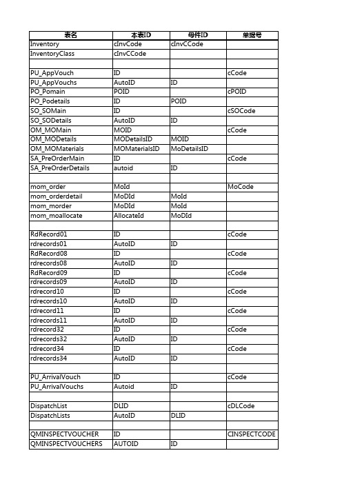
表名本表id母件id单据号inventorycinvcodecinvccodeinventoryclasscinvccodepuappvouchidccodepuappvouchsautoididpopomainpoidcpoidpopodetailsidpoidsosomainidcsocodesosodetailsautoididommomainmoidccodeommodetailsmodetailsidmoidommomaterialsmomaterialsidmodetailsidsapreordermainidccodesapreorderdetailsautoididmomordermoidmocodemomorderdetailmodidmoidmommordermodidmoidmommoallocateallocateidmodidrdrecord01idccoderdrecords01autoididrdrecord08idccoderdrecords08autoididrdrecord09idccoderdrecords09autoididrdrecord10idccoderdrecords10autoididrdrecord11idccoderdrecords11autoididrdrecord32idccoderdrecords32autoididrdrecord34idccoderdrecords34autoididpuarrivalvouchidccodepuarrivalvouchsautoididdispatchlistdlidcdlcodedispatchlistsautoiddlidqminspectvoucheridcinspectcodeqminspectvouchersautoididqmcheckvoucheridccheckcodeqmcheckvouchersautoididqmrejectvoucheridcrejectcodeqmrejectvouchersautoididqmscrapdisposecscrapdiscodebombombomidbomparentautoidbomidparentidbomopcomponentopcomponentidbomidbaspartpartidbomopcomponentoptoptionsidsfcopera
使用@Component注解时@Autowired注入为null怎么解决
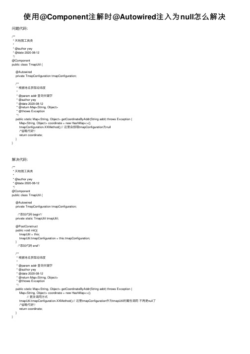
使⽤@Component注解时@Autowired注⼊为null怎么解决问题代码:/*** 天地图⼯具类** @author ywy* @date 2020-08-12*/@Componentpublic class TmapUtil {@Autowiredprivate TmapConfiguration tmapConfiguration;/*** 根据地名获取经纬度** @param addr 查询关键字* @author ywy* @date 2020-08-12* @return Map<String, Object>* @throws Exception*/public static Map<String, Object> getCoordinateByAddr(String addr) throws Exception {Map<String, Object> coordinate = new HashMap<>();tmapConfiguration.XXMethod();// 这⾥会报错tmapConfiguration为null/*省略代码*/return coordinate;}}解决代码:/*** 天地图⼯具类** @author ywy* @date 2020-08-12*/@Componentpublic class TmapUtil {@Autowiredprivate TmapConfiguration tmapConfiguration; /*添加代码 begin*/private static TmapUtil tmapUtil;@PostConstructpublic void init(){tmapUtil = this;tmapUtil.tmapConfiguration = this.tmapConfiguration;} /*添加代码 end*//*** 根据地名获取经纬度** @param addr 查询关键字* @author ywy* @date 2020-08-12* @return Map<String, Object>* @throws Exception*/public static Map<String, Object> getCoordinateByAddr(String addr) throws Exception {Map<String, Object> coordinate = new HashMap<>(); // 更改调⽤⽅式tmapUtil.tmapConfiguration.XXMethod();// 这⾥tmapConfiguration作为tmapUtil的属性调⽤不再是null了/*省略代码*/return coordinate;}}。
- 1、下载文档前请自行甄别文档内容的完整性,平台不提供额外的编辑、内容补充、找答案等附加服务。
- 2、"仅部分预览"的文档,不可在线预览部分如存在完整性等问题,可反馈申请退款(可完整预览的文档不适用该条件!)。
- 3、如文档侵犯您的权益,请联系客服反馈,我们会尽快为您处理(人工客服工作时间:9:00-18:30)。
以下SQL语句用于查询名为 "Tom"的客户的家庭地址: select PROVINCE,CITY,STREET,ZIP CODE from CUSTOMERS as c, ADDRESS as a where c.HOME_ADDRESS_ID =a.ID and = 'Tom';
粗粒度关系数据模型
持久化Customer对象
当Hibernate持久化Customer对象时,会 自动保存两个Address组件类对象. Hibernate执行以下SQL语句:
insert into CUSTOMERS (ID,NAME,HOME_PROVINCE,HOME_CITY,HOME_STREET,HOME_ZIPCODE, COM_PROVINCE,COM_CITY,COM_STREET,COM_ZIPCODE) values (1, 'Tom','province1','city1','street1','100001','province2','city2','street2','200002');
组成关系的特征
Customer类与Address类之间为组成 关系,它们的关系有以下特征:
Address Address对象的生命周期依赖于 Customer对象.当删除一个Customer 对象,应该把相关的Address对象删除. 一个Address对象只能属于某个特定的 Customer对象,不能被其他Customer 对象共享.
CUSTOMERS表参照ADDRESS表
建立关系数据模型的一个重要 原则是在不会导致数据冗余的 前提下,尽可能减少数据库表 的数目以及表之间的外键参照 关系.因为如果表之间的外键 参照关系很复杂,那么数据库 系统在每次对关系数据进行插 入,更新,删除和查询等SQL 操作时,都必须建立多个表的 连接,这是很耗时的操作,会 影响数据库的运行性能.
映射组成关系
教学内容
创建具有组成关系的域模型 创建粗粒度关系数据模型 映射组成关系 区分值类型和实体类型
Fine-grained object models
A major objective of the Hibernate project is support for fine-grained object models, which we isolated as the most important requirement for a rich domain model. It's one reason we've chosen POJOs. In crude terms, fine-grained means "more classes than tables." This object model achieves improved cohesion and greater code reuse and is more understandable.
区分值(Value)类型和实体(Entity)类型
Hibernate把持久化类的属性分为两种: 值(Value)类型和实体(Entity)类型. 值类型和实体类型的最重要的区别是前 者没有OID,不能被单独持久化,它的生 命周期依赖于所属的持久化类的对象的 生命周期,组件类型就是一种值类型; 而实体类型有OID,可以被单独持久化.
create table CUSTOMERS ( ID bigint not null, NAME varchar(15), HOME_STREET varchar(255), HOME_CITY varchar(255), HOME_PROVINCE varchar(255), HOME_ZIPCODE varchar(255), COM_STREET varchar(255), COM_CITY varchar(255), COM_PROVINCE varchar(255), COM_ZIPCODE varchar(255), primary key (ID));
在以上属性中,name,age,birthday,homeAddress以及comAddress都是值类 型属性,而currentCompany是实体类型属性,orders集合中的Order对象也是实体 类型属性.当删除一个Customer持久化对象时,Hibernate会从数据库中删除所有 值类型属性对应的数据,但是实体类型属性对应的数据有可能依然保留在数据库 中,也有可能被删除,这取决于是否在映射文件中设置了级联删除.假如对 orders集合设置了级联删除,那么删除Customer对象时,也会删除orders集合中 的所有Order对象.假如没有对currentCompany属性设置级联删除,那么删除一 个Customer对象时,currentCompany 属性引用的Company对象依然存在.
private Customer customer; public Customer getCustomer() { return this.customer; } public void setCustomer(Customer customer) { this.customer = customer; }
Hibernate net.sf.hibernate.MappingException: Unknown entity class: mypack.Address
区分值(Value)类型和实体(Entity)类型
Address类没有OID,这是Hibernate组件的一个重要特 征.由于Address类没有OID,因此不能通过Session来 单独保存,更新,删除或加载一个Address对象,例如 以下每行代码都会抛出MappingException异常:
持久化Customer对象
tx = session.beginTransaction(); Customer customer=new Customer(); Address homeAddress=new Address("province1","city1","street1","100001",customer); Address comAddress=new Address("province2","city2","street2","200002",customer); customer.setName("Tom"); customer.setHomeAddress(homeAddress); customer.setComAddress(comAddress); session.save(customer); mit();
试图单独保存一个Address对象
tx = session.beginTransaction(); Address address=new Address("province1","city1","street1","100001",null); session.save(address); mit();
用<component>元素来映射homeAddress属性 <component>元素还包含一个<parent>子元素和一系 列<property>子元素.<parent>元素指定Address类 所属的整体类,这里设为customer,与此对应,在 Address类中应该定义一个customer属性,以及相关的 getCustomer()和setCustomer()方法:
<component>元素表明homeAddress属性是Customer类的一个组 成部分,在Hibernate中称之为组件.<component>元素有两个 属性:
name: 设定被映射的持久化类的属性名,此处为Customer类的 homeAddress属性. class:设定homeAddress属性的类型,此处表明homeAddress属性 为Address类型.
域模型和关系数据模型
域模型中类的数目比关系数据模型中表的数目多
用<component>元素来映射homeAddress属性
<component name="homeAddress" class="mypack.Address"> <parent name="customer" /> <property name="street" type="string" column="HOME_STREET"/> <property name="city" type="string" column="HOME_CITY"/> <property name="province" type="string" column="HOME_PROVINCE"/> <property name="zipcode" type="short" column="HOME_ZIPCODE"/> </component>
区分值(Value)类型和实体(Entity)类型 We're advocating a design in which there are more persistent classes than tables. One row represents multiple objects. Because database identity is implemented by primary key value, some persistent objects won't have their own identity. In effect, the persistence mechanism implements pass-byvalue semantics for some classes.
