LTC3863:DC/DC控制器
Agilent E3632U 电源用户指南说明书

用户指南Agilent T echnologies E3632ADC 电源版权© 1997-2000安捷伦科技公司(Agilent Technologies)保留所有权利出版历史第 2版2000 年10 月新版手册是对原手册的完整修订每版之间的更新内容将以附加页和更换页的方式供您合并到本手册中本页的日期只有在新版发行时才更改商标信息Windows Windows 95 和 Windows NT 是 Microsoft Corp.的注册商标产品认证安捷伦科技公司认证本产品自出厂时符合其公布的规格安捷伦进一步认证本产品的校准测量符合美国国家标准和技术局此前为国家标准局为校准设备规定的测量范围并符合其它国际标准组织成员的校准设备的标准保修安捷伦对本产品的材料及工艺自出厂之日起给予为期三年的质量保证本产品与其它安捷伦产品集成时成为其它安捷伦产品的一部分安捷伦可改变本产品的保修期限和条件在保用期内安捷伦将负责维修或更换由安捷伦自行决定经证实有缺陷的产品保修期自交货之日起或自安装之日起如果由安捷伦安装开始计算保修服务本产品如果需要保证服务或修理必须将其送回安捷伦维修部门将产品送回安捷伦进行保修服务时用户应预付发往安捷伦的运费安捷伦则负责支付返程运费然而如果从其它国家将产品送回安捷伦则所有的运费关税及其它税款均由用户负担保修限制上述保修条件不适用于由以下原因所造成的损坏不正确或不适当地维修产品用户使用自己的产品或界面未经授权地修理或误用在指定环境外操作本产品或在不恰当的现场装配和维修等本产品的任何电路设计和连接完全由用户自行负责安捷伦不保证用户自行安装的电路的性能以及由此造成的安捷伦产品的故障除上述保证外没有任何其它明示或暗示的保证在当地法律允许的情况下安捷伦对本产品不作任何其它口头形式或书面形式上的明示或暗示的保证并且特别声明没有涉及特定用途的适销性或适用性或满意质量的暗示保证或条款对于澳大利亚和新西兰的交易:除非法律许可本声明中所含条款并不排除限制或修改适用于本产品销售的强制性法定权利而是对其的补充唯一的补救方法在当地法律允许的情况下此处提供的补救方法是用户唯一且仅有的补救方法安捷伦对任何直接间接特殊偶然或继发的损失包括失去利润或丢失数据无论是根据合同侵权赔偿或任何其它法理都概不负责声明本文档中包含的信息如有变动恕不另行通知在当地法律允许的情况下安捷伦对本资料不作任何的保证包括但不仅限于特定目的适销性和适用性的暗示保证对本资料可能包含的错误或因提供执行或使用本资料而导致的任何偶然和继发的损失安捷伦概不负责未经安捷伦事先书面许可不得影印复制或改编本文档的任何部分限制的权利软件和文档完全以个人经费开发它们根据下列条款交货并获得许可这些条款中的任何一个都适用DFARS 252.227-70131988 年 10月DFARS 252.211-70151991 年 5月或DFARS 252.227-70141995 年 6月中定义的商业计算机软件FAR 2.101(a) 中定义的商业条款或FAR 52.227-191987 年 6月或任何等同的代理规定或合同条款中定义的限制的计算机软件您对软件和文档资料只拥有 FAR 或 DFARS 相应条款或所涉及产品的安捷伦标准软件协议中规定的权利安全信息不要在本产品上安装替代零件或执行任何未经授权的修改请将本产品送回安捷伦销售与维修部门维修以确保其安全特性安全符号警告提醒使用者注意可能导致人员伤亡的操作程序做法或情况等注意提醒使用者注意可能导致仪器损坏或数据永久丢失的操作程序做法或情况等接地地线符号机架地线符号请参考手册中的特定警告和注意信息以避免人员伤害或设备损坏可能存在危险电压警告仪器内部没有操作人员可维修的部件如果需要维修服务请与受过培训维修人员联系警告要预防火灾更换的保险丝必须符合指定的类型和额定电流!手册编号E3632-904182000 年 10月第2版马来西亚印刷Agilent E3632A 是配有 GPIB 和 RS-232 接口的直流电源可提供高性能的 120 瓦单一输出具有两种输出量程它将工作台功能与系统功能相结合针对您的设计和测试要求提供了多用途解决方案便利的工作台功能•双量程单一输出•易于使用的旋钮控制设置•高可见度的真空荧光显示器•高精度和高解析度•远程电压检测•过压保护和过流保护•输出开/关•出色的负载和线路稳压以及低波纹和低噪声•操作状态存储•带有防滑支脚的便携式耐用机箱灵活的系统功能•GPIB (IEEE-488) 和 RS-232 接口是标准配置•SCPI可编程仪器的标准命令兼容性•易于从前面板完成的 I/O 设置•软件校准因此不必进行内部调整Agilent E3632A DC 电源前面板总览1 15V/7A 量程选择键2 30V/4A 量程选择键3过压保护键4过电流保护键5极限显示键6调用操作状态键7存储操作状态/本地键 8错误/校准键9 I/O 配置/加密键10输出开/关键11控制旋钮12解析度选择键13电压/电流调整选择键23115V/7A 量程选择键 用于选择 15V/7A量程并允许 15V/7A满量程输出230V/4A 量程选择键 用于选择 30V/40A 量程并允许 30V/4A满量程输出3过压保护键用于启用或禁用过压保护功能设置断路电压电平和清除过压状态4过流保护键用于启用或禁用过电流保护功能设置断路电流电平和清除过流状态5极限显示键用于在显示屏上显示电压和电流极限值可使用旋钮设置极限值6调用操作状态键从位置12或3调用先前存储的操作状态7存储操作状态/本地键1将操作状态存储在位置12或3或者使电源从远程界面模式返回本地模式8错误/校准键2 显示操作过程自检和校准时产生的错误码或者启用校准模式电源在执行校准前必须已解密有关如何校准的详细信息参见Service Guide 9I/O 配置/安全键3 配置远程界面的电源/或者对电源校准进行加密或解密有关如何对电源加密与解密的详细信息参见Service Guide 10输出开/关键启用或禁用电源输出此键在开和关之间切换11控制旋钮通过顺时针或逆时针旋转增加或减少闪烁数字的值12解析度选择键将闪烁的数字左移或右移13电压/电流调整选择键选择电压或电流调节的旋钮控制功能1当电源处于远程界面模式时此键可作为本地键使用2启动电源时可按住此键启用校准模式3当电源处于校准模式时此键可作为加密或解密键使用4前面板的电压和电流极限设置可用以下方法从前面板设置电压和电流极限值12键以在显示屏上显示极限值3并用控制旋钮将闪烁的数值如果极限显示超时则再次按4电流调整选择键将旋钮设置为电流控制模式5用解析度选择键将闪烁的数字移到相应的位置并用控制旋钮将闪烁的数字值改为所需的电流极限值6按下 键以启用输出大约五秒钟后显示屏自动进入输出监视模式显示输出的电压和电流或者再次按 键显示屏将立即进入输出监视模式注可使用远程界面命令禁用所有的前面板键和控制钮Agilent E3632A 必须处于本地模式时前面板键和控制钮才会起作用电流调整选择键解析度选择键和控制旋钮Display Limit Output On/Off Output On/Off5显示屏指示灯Adrs表明电源通过远程界面收听或通话Rmt表明电源处于远程界面模式15V 表明所选的是 15V/7A量程30V 表明所选的是 30V/4A量程OVP指示灯亮时表明启用了过压保护功能或者在指示灯闪烁时表明过压保护电路导致电源关闭OCP 指示灯亮时表明启用了过电流保护功能或者在指示灯闪烁时表明过流保护电路导致电源关闭CAL表明电源处于校准模式Limit 表明显示屏显示的是电压和电流的极限值ERROR 检测到硬件或远程界面命令有错误且尚未清除错误位OFF禁用了电源输出详细信息参见第 33页Unreg电源的输出不稳定既不是 CV 输出也不是 CC输出CV电源处于恒压模式CV电源处于恒定电流模式要查看显示屏指示灯请在启动电源时按下键Display Limit后面板总览使用前面板键以•选择 GPIB 或 RS-232 接口参见第 3 章•设置 GPIB 总线地址参见第 3 章•设置 RS-232 的波特率和奇偶校验参见第 3 章1电源线电压设置2电源线保险管座3交流电源输入接口4电源线模块5 GPIB (IEEE-488) 接口连接器6 RS-232 接口连接器I/O Config67本书内容概述 第 1章是电源的一般性介绍此外还提供有关检查电源连接交流电源以及选择电源线电压的规程初始操作 第 2 章确保电源产生额定输出并正确地响应前面板的操作前面板操作 第 3章详细介绍前面板键的用法以及如何使用这些键从前面板操作电源此外还讲述了如何配置电源的远程界面并简要地介绍了提供校准功能远程界面参考资料 第 4 章所含的参考信息可以帮助您通过远程界面对电源编程此外还介绍如何对状态报告编程错误消息 第 5 章列出使用电源时可能出现的错误消息每条错误消息列出了有助于您诊断并解决问题的信息应用程序 第 6 章提供了某些远程界面应用程序可帮助您开发自己的应用程序教程 第 7章介绍线性电源的基本操作并提供有关操作和使用 AgilentE3632A电源的具体细节规格 第 8章列出电源的技术规格如果您有电源操作方面的问题在美国请拨打电话1-800-452-4844 或就近与安捷伦科技公司的销售部门联系如果自购买之日起三年内Agilent E3632A 出现故障安捷伦将免费修理或更换在美国请拨打电话 1-800-258-5165ExpressExchange或就近与安捷伦科技公司的销售部门联系8目录第 1 章概述安全注意事项 14安全和 EMC 要求 14选件和附件 15选件 15附件 15说明 16安装 19初始检查 19冷却和安置 19输入电源要求 22电源线 22电源线电压选择 22第 2 章初始操作初步检查 27加电检查 28输出检查 29电压输出检查 29电流输出检查 30第 3 章前面板操作前面板操作概述 33恒压操作 34恒定电流操作 36存储和调用操作状态 38编写过压保护程序 40设置 OVP 电平和启用 OVP 电路 40检查 OVP 操作 41清除过压状态 41编写过流保护程序 43设置 OCP 电平和启用 OCP 电路 43检查 OCP 操作 44清除过流状态 44进行远程电压检测 46CV 稳压 46额定输出 46输出噪声 46稳定性 46远程电压检测连接 47禁用输出 489目录使用外部继电器禁用输出 49旋钮锁定 49与系统相关的操作 50自检 50出错状况 51显示屏控制 52固件版本查询 53SCPI 语言版本 53远程界面配置 54远程界面选择 54GPIB 地址 55波特率选择 (RS-232) 55奇偶校验选择 (RS-232) 55设置 GPIB 地址 56设置波特率和奇偶校验 (RS-232) 57GPIB 接口配置 59RS-232 接口配置 60RS-232 配置概述 60RS-232 数据帧格式 60连接到计算机或终端 61DTR / DSR 信号交换协议 62RS-232 故障排除 63校准概述 64校准加密 64校准信息 68第 4 章远程界面参考资料SCPI命令摘要 71简化的编程概述 76使用APPLy命令 76使用低级命令 76读取查询响应 77选择触发源 77电源编程范围 78使用APPLy命令 79输出设置和操作命令 80触发命令 86触发源选择 86触发命令 88与系统相关的命令 89校准命令 93RS-232 接口命令 951011目录SCPI 状态寄存器 96什么是事件寄存器 96什么是允许寄存器 96SCPI 状态系统 97可疑状态寄存器 98标准事件寄存器 99状态字节寄存器 100使用服务请求 (SRQ) 和串行查询 101使用 *STB? 命令读取状态字节 102使用信息可用位 (MAV) 102使用 SRQ 中断总线控制器 102确定命令序列何时完成 103当数据位于输出缓冲区时使用 *OPC 发出信号 103状态报告命令 104SCPI 语言简介 106本手册使用的命令格式 107命令分隔符 108使用 MIN 和 MAX 参数 108查询参数设置 109SCPI 命令终止符 109IEEE-488.2 常用命令 109SCPI 参数类型 110暂停进行中的输出 111SCPI 符合信息 112IEEE-488 符合信息 115第 5 章 错误消息执行错误 119自检错误 124校准错误 125第 6 章 应用程序用于 GPIB(IEEE 488) 的 C++ 实例 129Windows 3.1 和 GPIB 的 Excel 5.0 实例 131第 7 章 教程Agilent E3632A 操作概述 137输出特性 139不稳定状态 141干扰信号 141目录连接负载 143输出绝缘 143多个负载 143远程电压检测 144负载考虑事项 145扩大电压和电流的输出范围 146串联连接 146并联连接 146远程编程 147可靠性 149第 8 章规格性能规格 153补充特性 155索引 159Declaration of Conformity 163 121概述14概述本章对电源进行了一般性介绍并提供了有关初始检查在工作台和机架中安置及冷却电源选择电源线电压以及将电源与交流电源连接的操作规程安全注意事项本电源是 I类安全仪器这表明它有保护性接地端子该端子必须通过带有三线接地插座的供电电源与地线连接在安装或操作之前应首先检查电源并回顾本手册中介绍的安全标记和操作规程具体步骤的安全信息位于本手册的相应章节中有关一般的安全信息另见本手册开始部分的安全信息安全和 EMC 要求本电源的设计符合下列安全和EMC电磁兼容性要求•IEC 1010-1(1990)/EN 61010-1(1993) + A2 (1995): Safety Requirements for Electrical Equipment for Measurement, Control, and Laboratory Use•CSA C22.2 No.1010.1-92: Safety Requirements for Electrical Equipment for Measurement, Control, and Laboratory Use•UL 1244: Electrical and Electric Measuring and Testing Equipment •EMC Directive 89/336/EEC•Low Voltage Directive: 73/23/EEC•EN 55011(1991) Group I, Class A/CISPR II(1990): Limits and Methods of Radio Interface Characteristics of Industrial, Scientific, and Medical(ISM) Radio-Frequency Equipment.•EN50082-1(1992):IEC 801-2(1991): Electrostatic Discharge RequirementsIEC 801-3(1984): Radiated Electromagnetic Field RequirementsIEC 801-4(1988): Electrical Fast Transient/Burst Requirements第 1章概述选件和附件151选件和附件选件选件0E3和0E9决定了出厂时选择哪种电源线电压标准单元的配置为 115 Vac ± 10%47-63 Hz 输入电压有关更改电源线电压设置的更详细信息请参见从本章第 22 页开始的电源线电压选择选件说明0E3230 Vac ± 10%, 47-63 Hz 输入电压0E9100 Vac ± 10%, 47-63 Hz 输入电压1CM机架安装工具包安捷伦产品编号5063-9243910额外的一套手册所使用的语言与您订购电源时选择的手册语言相同*附件下列附件可从当地安捷伦科技公司销售部门单独订购或与电源一起订购安捷伦编号说明10833A GPIB电缆 1 米 3.3 英尺10833B GPIB电缆 2 米 6.6 英尺34398A RS-232, 9 针孔端转 9 针孔端 2.5 米8.2 英寸电缆另加9 针针端转25针孔端转接器34399ARS-232 转接器套件内含 4个转接器用于 PC或打印机的 9 针针端转 25 针针端转接器用于 PC 或打印机的 9 针针端转 25 针孔端转接器用于调制解调器的 9 针针端转 25针针端转接器用于调制解调器的 9 针针端转 9 针针端转接器*要订购单独的一套用户指南和Service Guide请订购安捷伦编号为E3632-90408 的产品第 1章 概述说明16说明Agilent E3632A DC电源兼有编程功能和线性电源的性能最适合作为供电系统使用可在本地从前面板或在远程通过 GPIB 和 RS-232接口对电源进行编程本电源具有两个量程允许在电流较低时有较高的电压或者电压较低时有较高电流您可从前面板或从远程界面选择所需的输出量程操作特性包括•15V/7A 或 30V/4A 的两个量程•恒压 (CV) 或恒定电流 (CC) 操作•过压保护 (OVP) 和过流保护 (OCP)•有三个存储位置 1 到 3可用于存储用户定义的操作状态•自动开机自检•负载电压的远程检测•用户可从前面板或通过远程界面校准前面板操作包括•操作简单的旋钮控制•输出量程选择•启用或禁用 OVP 和 OCP 功能•设置 OVP 和 OCP 断路电平•清除 OVP 和 OCP 状态•设置和显示电压和电流极限值•保存和调用操作状态•使电源从远程界面模式返回本地模式•显示远程界面错误消息•校准电源包括更改校准密码•配置电源的远程界面•启用或禁用输出第 1章 概述说明171从远程界面操作时电源可同时作为收话方和通话方使用外部控制器您可以指示电源设置输出并通过 GPIB 或 RS-232 传回状态数据包括下列功能•电压和电流编程•电压和电流回读•当前和已存储状态的回读•编程语法错误检测•完整的自检前面板VFD真空荧光屏包括•显示输出电压和电流的实际值计量模式•或显示电压和电流的极限值极限模式•通过指示灯检查操作状态•通过错误代码错误消息检查错误类型将电源的输出和机座地线连接到前面板的接线柱上警告 如果电源输出浮置电压大于 ±60 Vdc 则操作者在机座处即有遭受电击的危险当使用未绝缘的金属短路条将 (+) 输出端子与 (+) 检测端子相连并将 (-) 输出端子和 (-) 检测端子相连时不要使输出浮置电压大于±60 Vdc第 1章 概述说明18警告 如果用绝缘体代替未绝缘的金属短路条或从端子上取下这些短路条以便任何操作者都不会接触到未绝缘输出导体则最大输出浮置电压可以达到 ±240 Vdc 现场所有导线的绝缘必须满足当前电压的要求电源附带有可拆卸的三线接地型电源线交流电源线的保险管位于后面板上可以取出可直接从前面板或通过 GPIB 或 RS-232 接口上的控制器使用校准命令校准电源校正系数存储在非易失性存储器中在输出编程时使用从前面板或控制器校准时不必卸下顶盖甚至不需要将电源从系统机箱中取出使用加密校准保护功能可以防止未经授权的校准第 1章 概述安装191安装初始检查当您收到电源时检查一下其在运输过程中是否发生了明显的损坏如有任何损坏请立即通知运输公司并与最近的安捷伦销售部门联络保修信息在本手册的最前面保存好包装材料以备将来将电源送回安捷伦科技公司时使用如要将电源送回安捷伦维修请随附一份标识物主和仪器型号的卡片并附上问题简述机械性检查通过此项检查确认键或旋钮没有破损机壳和面板表面没有凹陷和刮痕显示屏也没有刮痕或破裂电气检查第 2 章介绍了初始操作步骤如果成功地完成这些步骤即可确信电源正按照技术规格的要求运行Service Guide 中提供了详细的电气检验步骤冷却和安置冷却电源在 0°C到 40°C 的温度范围内运行时不会降低性能在40 °C到 55 °C 的情况下输出电流会降低风扇通过后面板抽进空气并从侧面排出以使电源冷却使用安捷伦的架装套件不会阻碍空气流通工作台操作安装电源时应在其两侧及后面留出足够空间以便空气流通安装在机架中时必须卸下橡皮缓冲垫第 1章 概述安装20机架安装可以使用三个选件工具包之一将电源安装在标准的 19英寸机架内选件1CM 安捷伦产品编号5063-9243是用于单个仪器的架装套件每个架装套件中都有安装规程和硬件任何同样尺寸的 Agilent System II 仪器都可架装在 E3632A 电源的旁边在架装电源之前应先拆下前后缓冲垫要卸下橡皮缓冲垫应先拉住一角然后将其滑出要架装单个仪器请订购转接器套件5063-9243第 1章 概述安装211要并排架装两个仪器请订购链锁套件 5061-9694 和边缘套件 5063-9214要在滑动支架上安装一或两台仪器请订购支架 5063-9256 和滑轨套件 1494-0015对于单个仪器还需订购填充板5002-4002第 1章 概述输入电源要求22输入电源要求可以在额定值为100 V 115 V 或230 V 频率为 47 到 63 Hz 的单相交流电下操作电源后面板上有一个标识指示出厂时设置的电源额定输入电压必要时可根据下一页的指示修改电源线电压的设置电源线电源出厂时配备有电源线其带有符合使用国标准的插头如果配备了错误的电源线请与最近的安捷伦科技公司销售和维修部门联系电源配备有三线接地型电源线第三根导线是地线只有在电源线插入正确的插座时电源才会接地仪器机箱未正确接地之前请勿操作电源电源线电压选择通过调整两个部件可完成电源线电压选择电源线电压选择器与后面板电源线模块上的电源线保险管要改变电源线电压请执行以下步骤第 1章 概述输入电源要求231安装正确的保险管 从电源线模块中卸下电源线电压选择器115 Vac 4 AT 230 Vac 2.5 AT 保险管断开电源线 使用平头螺丝刀从后面板上卸下保险管座旋转电源线电压选择器直到出现正确的电压100115 和保险管座重新装到后面板中第 1章概述输入电源要求242初始操作26初始操作本章介绍了三项基本测试自动加电测试包括自检它检查内部微处理器并让用户直观地检查显示屏输出检查可确保电源产生额定输出并正确地响应前面板的操作有关完整的性能和/或验证测试参见Service Guide 有经验的用户和无经验的用户都应参阅本章内容以便在操作仪器前先执行特定的检查在本章中所使用的按键显示在左页边中第 2章 初始操作初步检查272初步检查以下步骤可帮助您检验电源是否可用1验证后面板上电源线电压的设置电源出厂时为使用国设置了合适的电源线电压值如果电压不正确请修改电压设置设置值有100115 或230 Vac2确保已安装正确的电源线保险管电源出厂时安装了合适于使用国的保险管用于 100 或 115 Vac 操作时必须使用 4 AT 保险管用于 230 Vac操作时必须使用 2.5 AT保险管3接上电源线并打开电源当您打开电源时前面板显示屏变亮同时自动进行加电自检如果需要更改电源线电压或电源线保险管请参见从第 22 页开始的电源线电压选择要更换 4 AT 保险管请订购安捷伦产品编号为 2110-0996 的产品要更换 2.5 AT 保险管请订购安捷伦产品编号为 2110-0999 的产品第 2章 初始操作加电检查28加电检查加电测试包括自动自检它检查内部的微处理器并让用户直观地检查显示屏打开前面板电源开关后您会在显示屏上依次观察到下列情况1显示屏上的所有字段包括所有指示灯将点亮大约1秒钟要检查指示灯请在打开电源时按住键2GPIB 地址或 RS-232 信息将显示约 1 秒钟电源出厂时在远程界面配置中将 GPIB 地址设置为5如果不是首次打开电源则可能会出现不同的界面 (RS-232) 或不同的 GPIB 地址如果需要更改远程界面配置请参见从第3 章第 54 页开始的远程界面配置315VOVPOCP和OFF 指示灯变亮其余的指示灯熄灭电源将进入加电/复位状态输出为禁用OFF 指示灯变亮选择15V/7A 量程15V 指示灯变亮并且选择用旋钮控制电压注意 OVP 和 OCP 指示灯也同时变亮4 启用输出按 键以启用输出OFF 指示灯熄灭而 15V OVP OCP 和 CV 指示灯变亮旋转旋钮可调整闪烁的数字注意显示屏处于计量模式计量模式是指显示屏显示实际的输出电压值和电流值注如果在加电自检时电源检测到错误则 ERROR 指示灯变亮详细信息参见第 5 章第 117 页的错误消息ADDR 05 (或 RS-232)Display Limit Output On/OffOutput On/Off。
LTC3813EG-PBF资料
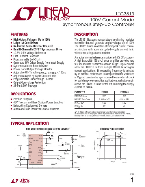
13813fbSynchronous Step-Up ControllerThe L TC 3813 is a synchronous step-up switching regulator controller that can generate output voltages up to 100V . The L TC3813 uses a constant off-time peak current control architecture with accurate cycle-by-cycle current limit, without requiring a sense resistor .A precise internal reference provides ±0.5% DC accuracy. A high bandwidth (25MHz) error amplifi er provides very fast line and load transient response. Large 1Ω gate drivers allow the L TC3813 to drive multiple MOSFETs for higher current applications. The operating frequency is selected by an external resistor and is compensated for variations in V IN and can also be synchronized to an external clock for switching-noise sensitive applications. A shutdown pin allows the L TC3813 to be turned off, reducing the supply current to 240μA.PARAMETER L TC3813L TC3814-5Maximum V OUT 100V 60V MOSFET Gate Drive 6.35V to 14V4.5V to 14V INTV CC UV + 6.2V 4.2V INTV CC UV –6V4Vn24V Fan Suppliesn 48V Telecom and Base Station Power Supplies n Networking Equipment, ServersnAutomotive and Industrial Control SystemsnHigh Output Voltages: Up to 100V n Large 1Ω Gate Driversn No Current Sense Resistor Requiredn Dual N-Channel MOSFET Synchronous Drive n ±0.5% 0.8V Voltage Reference n Fast T ransient Response n Programmable Soft-Startn Generates 10V Driver Supply from Input Supply n Synchronizable to External Clock n Power Good Output Voltage Monitor n Adjustable Off-Time/Frequency: t OFF(MIN) < 100ns n Adjustable Cycle-by-Cycle Current Limit n Programmable Undervoltage Lockout n Output Overvoltage Protection n 28-Pin SSOP PackageHigh Effi ciency High Voltage Step-Up ConverterEffi ciency vs Load CurrentT YPICAL APPLICATIONF EATURESA PPLICATIONSD ESCRIPTION L , L T , L TC and L TM are registered trademarks of Linear Technology Corporation.All other trademarks are the property of their respective owners. Protected by U.S. Patents, including 5481178, 5847554, 6304066, 6476589, 6580258, 6677210, 6774611.OUTLOAD (A)E F F I C I E N C Y (%)909585801003813 TA01b0423813fbSupply VoltagesINTV CC , DRV CC.......................................–0.3V to 14V (DRV CC - BGRTN), (BOOST - SW)..........–0.3V to 14V BOOST .................................................–0.3V to 114V BGRTN ........................................................–5V to 0V EXTV CC ..................................................–0.3V to 15V (NDRV - INTV CC ) Voltage ...........................–0.3V to 10V SW , SENSE + Voltage ...................................–1V to 100V I OFF Voltage ..............................................–0.3V to 100V SS Voltage ...................................................–0.3V to 5V PGOOD Voltage ............................................–0.3V to 7V V RNG , V OFF , SYNC, SHDN , UVIN Voltages ........................................–0.3V to 14V PLL/LPF , FB Voltages .................................–0.3V to 2.7V TG, BG, INTV CC , EXTV CC RMS Currents .................50mA Operating Temperature Range (Note 2)L TC3813E .............................................–40°C to 85°C L TC3813I............................................–40°C to 125°C Junction Temperature (Notes 3, 7)........................125°C Storage Temperature Range ...................–65°C to 150°C Lead Temperature (Soldering, 10 sec) ..................300°C(Note 1)The l denotes specifi cations which apply over the full operating temperature range, otherwise specifi cations are at T A = 25°C, INTV CC = DRV CC = V BOOST = V OFF = V RNG = SHDN = UV IN = V EXTVCC = V NDRV = 10V , V SYNC = V SENSE + = V SENSE – = V BGRTN = V SW = 0V , unless otherwise specifi ed.SYMBOL PARAMETER CONDITIONSMIN TYP MAX UNITSMain Control Loop INTV CC INTV CC Supply Voltage l6.3514V I Q INTV CC Supply CurrentINTV CC Shutdown Current SHDN > 1.5V , I NTVCC = 9.5V (Notes 4, 5)SHDN = 0V32406600mA μA I BOOSTBOOST Supply CurrentSHDN > 1.5V (Note 5)SHDN = 0V27004005μA μAPIN CONFIGURATIONLEAD FREE FINISH TAPE AND REEL PART MARKING PACKAGE DESCRIPTION TEMPERATURE RANGE L TC3813EG#PBF L TC3813EG#TRPBF L TC3813EG 28-Lead Plastic SSOP –40°C to 85°C L TC3813IG#PBFL TC3813IG#TRPBFL TC3813IG28-Lead Plastic SSOP–40°C to 125°CConsult L TC Marketing for parts specifi ed with wider operating temperature ranges.Consult L TC Marketing for information on non-standard lead based fi nish parts.For more information on lead free part marking, go to: http://www.linear .com/leadfree/ For more information on tape and reel specifi cations, go to: http://www.linear .com/tapeandreel/A BSOLUTE MAXIMUM RATINGS ORDER INFORMATIONELECTRICAL CHARACTERISTICS33813fbSYMBOL PARAMETER CONDITIONSMIN TYP MAX UNITSV FBFeedback Voltage(Note 4)0°C to 85°C –40°C to 85°C–40°C to 125°C (I-Grade)l l l 0.7960.7940.7920.7920.8000.8000.8000.8000.8040.8060.8060.808V V V V ΔV FB,LINE Feedback Voltage Line Regulation 7V < INTV CC < 14V (Note 4)l0.0020.02%/V V SENSE(MAX)Maximum Current Sense ThresholdV RNG = 2V , V FB = 0.76V V RNG = 0V , V FB = 0.76V V RNG = INTV CC , V FB = 0.76V 2567017032095215384120260mV mV mV V SENSE(MIN)Minimum Current Sense ThresholdV RNG = 2V , V FB = 0.84V V RNG = 0V , V FB = 0.84V V RNG = INTV CC , V FB = 0.84V –300–85–200mV mV mV I VFB Feedback CurrentV FB = 0.8V20150nA A VOL (EA)Error Amplifi er DC Open Loop Gain 65100dB f U Error Amp Unity Gain Crossover Frequency (Note 6)25MHz I SYNC SYNC Current SYNC = 10V01μA V SHDN Shutdown Threshold 1.21.52V I SHDN SHDN Pin Input Current 01μA I SS SS Source Current V SS > 0.5V 0.7 1.4 2.5μA V VINUVV IN Undervoltage LockoutV IN Rising V IN Falling Hysteresis l l 0.860.780.070.880.800.100.920.820.12V V V V VCCUV INTV CC Undervoltage LockoutINTV CC Rising Hysteresis l 6.056.20.5 6.35V V Oscillator and Phase-Locked Loop t OFF Off-Time I OFF = 100μA I OFF = 300μA 1.555151.856052.15695μs ns t OFF(MIN)Minimum Off-Time I OFF = 2000μA100nst ON(MIN)Minimum On-Time350ns t OFF(PLL)t OFF Modulation Range by PLL Down Modulation Up ModulationI OFF = 100μA, V PLL/LPF = 0.6V I OFF = 100μA, V PLL/LPF = 1.8V 2.20.63.61.251.8μs μs I PLL/LPFPhase Detector Output Current Sinking Capability Sourcing Capability f PLLIN < f SW f PLLIN > f SW 15–25μA μA Driver I BG,PEAK BG Driver Peak Source Current V BG = 0V 1.52A R BG,SINK BG Driver Pulldown R DS(ON)1 1.5ΩI TG,PEAK TG Driver Peak Source Current V TG – V SW = 0V1.52A R TG,SINK TG Driver Pulldown R DS(ON)11.5ΩPGOOD Output ΔV FBOV PGOOD Upper Threshold PGOOD Lower Threshold V FB Rising V FB Falling 7.5–7.510–1012.5–12.5%%ΔV FB,HYST PGOOD Hysteresis V FB Returning 1.53%V PGOODPGOOD Low VoltageI PGOOD = 5mA0.30.6VThe l denotes specifi cations which apply over the full operatingtemperature range, otherwise specifi cations are at T A = 25°C, INTV CC = DRV CC = V BOOST = V OFF = V RNG = SHDN = UV IN = V EXTVCC =V NDRV = 10V , V SYNC = V SENSE + = V SENSE – = V BGRTN = V SW = 0V , unless otherwise specified. E LECTRICAL CHARACTERISTICS43813fbNote 1: Stresses beyond those listed under Absolute Maximum Ratings may cause permanent damage to the device. Exposure to any Absolute Maximum Rating condition for extended periods may affect device reliability and lifetime.Note 2: The L TC3813E is guaranteed to meet performance specifi cations from 0°C to 85°C. Specifi cations over the –40°C to 85°C operatingtemperature range are assured by design, characterization and correlation with statistical process controls. The L TC3813I is guaranteed to meet performance specifi cations over the full –40°C to 125°C operating temperature range.Note 3: T J is calculated from the ambient temperature T A and power dissipation P D according to the following formula: L T C 3813: T J = T A + (P D • 100°C/W)SYMBOL PARAMETERCONDITIONS MINTYP MAX UNITS I PGOOD PGOOD Leakage Current V PGOOD = 5V 02μA PG Delay PGOOD DelayV FB Falling125μsV CC RegulatorsV EXTVCCEXTV CC Switchover Voltage EXTV CC Rising EXTV CC Hysteresis l6.40.1 6.70.250.5V V V INTVCC,1INTV CC Voltage from EXTV CC 10.5V < V EXTVCC < 15V 9.41010.6V ΔV EXTVCC,1V EXTVCC - V INTVCC at Dropout I CC = 20mA, V EXTVCC = 9.1V 170250mV ΔV LOADREG,1INTV CC Load Regulation from EXTV CC I CC = 0mA to 20mA, V EXTVCC = 12V 0.01%V INTVCC,2INTV CC Voltage from NDRV Regulator Linear Regulator in Operation 9.41010.6V ΔV LOADREG,2INTV CC Load Regulation from NDRV I CC = 0mA to 20mA, V EXTVCC = 00.01%I NDRV Current into NDRV Pin V NDRV – V INTVCC = 3V 204060μA V CCSR Maximum Supply VoltageT rickle Charger Shunt Regulator 15V I CCSRMaximum Current into NDRV/INTV CCT rickle Charger Shunt Regulator , INTV CC ≤ 16.7V (Note 8)10mAThel denotes specifi cations which apply over the full operating temperature range, otherwise specifi cations are at T A = 25°C, INTV CC = DRV CC = V BOOST = V OFF = V RNG = SHDN = UV IN = V EXTVCC =V NDRV = 10V , V SYNC = V SENSE + = V SENSE – = V BGRTN = V SW = 0V , unless otherwise specified.Note 4: The L TC3813 is tested in a feedback loop that servos V FB to thereference voltage with the I TH pin forced to a voltage between 1V and 2V .Note 5: The dynamic input supply current is higher due to the power MOSFET gate charging being delivered at the switching frequency (Q G • f SW ).Note 6: Guaranteed by design. Not subject to test.Note 7: This IC includes overtemperature protection that is intended to protect the device during momentary overload conditions. Junction temperature will exceed 125°C when overtemperature protection is active. Continuous operation above the specifi ed maximum operating junction temperature may impair device reliability.Note 8: I CC is the sum of current into NDRV and INTV CC .E LECTRICAL CHARACTERISTICS53813fbLoad T ransient ResponseStart-UpOvercurrent OperationEffi ciency vs Load CurrentFrequency vs Input VoltageFrequency vs Load CurrentCurrent Sense Threshold vs I TH VoltageOff-Time vs I OFF CurrentOff-Time vs V OFF VoltageTYPICAL PERFORMANCE CHARACTERISTICSV OUT 200mV/DIV100μs/DIVFIGURE 14 CIRCUIT V IN = 12V0A TO 4A LOAD STEP3813 G01I OUT2A/DIV3813 G021ms/DIVV OUT 20V/DIVSS 4V/DIV I L 5A/DIVFRONT PAGE CIRCUIT V IN = 24V I LOAD= 2A3813 G03500μs/DIVV OUT 20V/DIVI L 5A/DIVFRONT PAGE CIRCUIT V IN = 24V R SHORT = 1ΩLOAD (A)0E F F I C I E N C Y (%)9095485801231003813 G04INPUT VOL TAGE (V)10F R E Q U E N C Y (k H z )2602803003035240220200152025403813 G05200220210230240250260280270LOAD CURRENT (A)0F R E Q U E N C Y (k H z )12343813 G06I TH VOL TAGE (V)–400C U R R E N T S E N S E T H R E S H O LD (m V )–300–200–10001002004000.51 1.523813 G072.53300I OFF CURRENT (μA)1010O F F -T I M E (n s )1001000100001001000100003813 G08V OFF VOL TAGE (V)0400500700 1.5 2.53813 G093002000.5123100600OF F -T I M E (n s )63813fbOff-Time vs TemperatureMaximum Current Sense Threshold vs V RNG VoltageMaximum Current Sense Threshold vs TemperatureFeedback Reference Voltage vs TemperatureDriver Peak Source Current vs TemperatureDriver Pulldown R DS(ON) vs TemperatureDriver Peak Source Current vs Supply VoltageDriver Pulldown R DS(ON)vs Supply VoltageT YPICAL PERFORMANCE CHARACTERISTICS TEMPERATURE (°C)–50O F F -T I M E (n s )64066068025753813 G10620600–2550100125580560V RNG VOL TAGE (V)0.5M A X I M U M C U R R E N T S E N S E T H R E S H O L D (m V )2003813 G1110001 1.53004002TEMPERATURE (°C)–50–25180M A X I M U M C U R R E N T S E N S E T H R E S H O L D (m V )200230050753813 G1219022021025100125TEMPERATURE (°C)–50–250.797R E F E R E N C E V O L T A G E (V )0.7990.803050753813 G130.7980.8020.8010.80025100125TEMPERATURE (°C)–501P E A K S O U R C E C U R R E N T (A )1.52.02.5–25025503813 G1475100125TEMPERATURE (°C)–50R D S (O N ) (Ω)1.251.50025753813 G151.000.75–25501001250.500.25DRV CC /BOOST VOLTAGE (V)568101214P E A K S O U R C E C U R R E N T (A )3.02.52.01.51.00.507911133813 G1615DRV CC /BOOST VOLTAGE (V)6R D S (O N ) (Ω)0.60.80.91.01.181011153813 G170.77912131473813fbEXTV CC LDO Resistance at Dropout vs TemperatureINTV CC Current vs TemperatureINTV CC Shutdown Current vs TemperatureINTV CC Current vs INTV CC VoltageINTV CC Shutdown Current vs INTV CC VoltageSS Pull-Up Current vs TemperatureI TH Voltage vs Load CurrentShutdown Threshold vs TemperatureTYPICAL PERFORMANCE CHARACTERISTICSTEMPERATURE (°C)–50R E S I S T A N C E (Ω)253813 G18842–25500141210675100125TEMPERATURE (°C)–50–250I N T V C C C U R R E N T (m A )24050753813 G191325100125TEMPERATURE (°C)–50I N T V C C C U R R E N T (μA )253813 G20200100–25050040030075100125INTV CC VOLTAGE (V)2.02.54.03.56103813 G211.51.024812140.503.0I N T V C C C U R R E N T (m A)INTV CC VOLTAGE (V)02002503006103813 G221501002481214500I N T V C C C U R R E N T (μA)TEMPERATURE (°C)–50S S C U R R E N T (μA )2325753813 G231–2550100125LOAD CURRENT (A)I T H V O L T A G E (V )1233813 G2401234TEMPERATURE (°C)–50S H U T D O W N T H R E S H O L D (V )2.0253813 G251.41.0–25500.80.62.21.81.61.275100125I OFF (Pin 1): Off-Time Current Input. Tie a resistor from V OUT to this pin to set the one-shot timer current and thereby set the switching frequency.V OFF (Pin 4): Off-Time Voltage Input. Voltage trip point for the on-time comparator. Tying this pin to an external resistive divider from the input makes the off-time pro-portional to V IN. The comparator defaults to 0.7V when the pin is grounded and defaults to 2.4V when the pin is connected to INTV CC.V RNG (Pin 5): Sense Voltage Limit Set. The voltage at this pin sets the nominal sense voltage at maximum output current and can be set from 0.5V to 2V by a resistive divider from INTV CC. The nominal sense voltage defaults to 95mV when this pin is tied to ground, and 215mV when tied to INTV CC.PGOOD (Pin 6): Power Good Output. Open-drain logic output that is pulled to ground when the output voltage is not between ±10% of the regulation point. The output voltage must be out of regulation for at least 125μs before the power good output is pulled to ground.SYNC (Pin 7): Sync Pin. This pin provides an external clock input to the phase detector. The phase-locked loop will force the rising top gate signal to be synchronized with the rising edge of the clock signal.I TH (Pin 8): Error Amplifi er Compensation Point and Cur-rent Control Threshold. The current comparator threshold increases with control voltage. The voltage ranges from 0V to 2.6V with 1.2V corresponding to zero sense voltage (zero current).V FB (Pin 9): Feedback Input. C onnect V FB through a resistor divider network to V OUT to set the output voltage.PLL/LPF (Pin 10): The phase-locked loop’s lowpass fi lter is tied to this pin. The voltage at this pin defaults to 1.2V when the IC is not synchronized with an external clock at the SYNC pin.SS (Pin 11): Soft-Start Input. A capacitor to ground at this pin sets the ramp rate of the maximum current sense threshold.SGND (Pin 12): Signal Ground. All small signal components should connect to this ground and eventually connect to PGND at one point.SHDN (Pin 13): Shutdown Pin. Pulling this pin below 1.5V will shut down the L TC3813, turn off both of the external MOSFET switches and reduce the quiescent supply cur-rent to 240μA.UVIN (Pin 14): UVLO Input. This pin is input to the internal UVLO and is compared to an internal 0.8V reference. An external resistor divider is connected to this pin and the input supply to program the undervoltage lockout voltage. When UVIN is less than 0.8V, the L TC3813 is shut down. NDRV (Pin 15): Drive Output for External Pass Device of the Linear Regulator for INTV CC. Connect to the gate of an external NMOS pass device and a pull-up resistor to the input voltage V IN or the output voltage V OUT.EXTV CC (Pin 16): External Driver Supply Voltage. When this voltage exceeds 6.7V, an internal switch connects this pin to INTV CC through an LDO and turns off the exter-nal MOSFET connected to NDRV, so that controller and gate drive are drawn from EXTV CC.INTV CC (Pin 17): Main Supply Pin. All internal circuits except the output drivers are powered from this pin. INTV CC should be bypassed to ground (Pin 10) with at least a 0.1μF capacitor in close proximity to the L TC3813.DRV CC (Pin 18): Driver Supply Pin. DRV CC supplies power to the BG output driver. This pin is normally connected to INTV CC. DRV CC should be bypassed to BGRTN (Pin 20) with a low ESR (X5R or better) 1μF capacitor in close proximity to the L TC3813.PIN FUNCTIONS83813fbBG (Pin 19): Bottom Gate Drive. The BG pin drives the gate of the bottom N-channel main switch MOSFET. This pin swings from BGRTN to DRV CC.BGRTN (Pin 20): Bottom Gate Return. This pin connects to the source of the pulldown MOSFET in the BG driver and is normally connected to ground. Connecting a negative supply to this pin allows the main MOSFET’s gate to be pulled below ground to help prevent false turn-on during high dV/dt transitions on the SW node. See the Applica-tions Information section for more details.SENSE+, SENSE– (Pin 25, Pin 21): Current Sense Com-parator Input. The (+) input to the current comparator is normally connected to SW unless using a sense resistor. The (–) input is used to accurately kelvin sense the bottom side of the sense resistor or MOSFET.SW (Pin 26): Switch Node Connection to Inductor and Bootstrap Capacitor. Voltage swing at this pin is from a Schottky diode (external) voltage drop below ground to V OUT.TG (Pin 27): Top Gate Drive. The TG pin drives the gate of the top N-channel synchronous switch MOSFET. The TG driver draws power from the BOOST pin and returns to the SW pin, providing true fl oating drive to the top MOSFET. BOOST (Pin 28): Top Gate Driver Supply. The BOOST pin supplies power to the fl oating TG driver. BOOST should be bypassed to SW with a low ESR (X5R or better) 0.1μF capacitor. An additional fast recovery Schottky diode from DRV CC to the BOOST pin will create a complete fl oating charge-pumped supply at BOOST.PIN FUNCTIONS93813fbFUNCTIONAL DIAGRAMV103813fbMain Control LoopThe L TC3813 is a current mode controller for DC/DC step-up converters. In normal operation, the top MOSFET is turned on for a fi xed interval determined by a one-shot timer (OST). When the top MOSFET is turned off, the bot-tom MOSFET is turned on until the current comparator I CMP trips, restarting the one-shot timer and initiating the next cycle. Inductor current is determined by sensing the voltage between the SENSE– and SENSE+ pins using a sense resistor or the bottom MOSFET on-resistance. The voltage on the I TH pin sets the comparator threshold cor-responding to the inductor peak current. The fast 25MHz error amplifi er EA adjusts this voltage by comparing the feedback signal V FB to the internal 0.8V reference volt-age. If the load current increases, it causes a drop in the feedback voltage relative to the reference. The I TH voltage then rises until the average inductor current again matches the load current.The operating frequency is determined implicitly by the top MOSFET on-time (t OFF) and the duty cycle required to maintain regulation. The one-shot timer generates a top MOSFET on-time that is inversely proportional to the I OFF current and proportional to the V OFF voltage. Connecting V OUT to I OFF and V IN to V OFF with a resistive divider keeps the frequency approximately constant with changes in V IN. The nominal frequency can be adjusted with an external resistor R OFF.For applications with stringent constant-frequency require-ments, the L TC3813 can be synchronized with an external clock. By programming the nominal frequency the same as the external clock frequency, the L TC3813 behaves as a con-stant-frequency part against the load and supply variations. Pulling the SHDN pin low forces the controller into its shutdown state, turning off both M1 and M2. Forcing a voltage above 1.5V will turn on the device.Fault Monitoring/ProtectionC onstant off-time current mode architecture provides accurate cycle-by-cycle current limit protection—a fea-ture that is very important for protecting the high volt-age power supply from output overcurrent conditions. The cycle-by-cycle current monitor guarantees that the inductor current will never exceed the value programmed on the V RNG pin.Overvoltage and undervoltage comparators OV and UV pull the PGOOD output low if the output feedback voltage exits a ±10% window around the regulation point after the internal 125μs power bad mask timer expires. Furthermore, in an overvoltage condition, M1 is turned off and M2 is turned on immediately and held on until the overvoltage condition clears.The L TC3813 provides two undervoltage lockout com-parators—one for the INTV CC/DRV CC supply and one for the input supply V IN. The INTV CC UV threshold is 6.2V to guarantee that the MOSFETs have suffi cient gate drive volt-age before turning on. The V IN UV threshold (UVIN pin) is 0.8V with 10% hysteresis which allows programming the V IN threshold with the appropriate resistor divider con-nected to V IN. If either comparator inputs are under the UV threshold, the L TC3813 is shut down and the drivers are turned off.Strong Gate DriversThe L TC3813 contains very low impedance drivers capable of supplying amps of current to slew large MOSFET gates quickly. This minimizes transition losses and allows paral-leling MOSFETs for higher current applications. A 100V fl oating high side driver drives the top side MOSFET and a low side driver drives the bottom side MOSFET (see Figure 1). The bottom side driver is supplied directly from the DRV CC pin. The top MOSFET drivers are biased from fl oating bootstrap capacitor C B, which normally is recharged during each off cycle through an external diodeOPERATIONV OUTOUTFigure 1. Floating TG Driver Supply and Negative BG Returnfrom DRV CC when the top MOSFET turns off. In an output overvoltage condition, where it is possible that the bot-tom MOSFET will be off for an extended period of time, an internal timeout guarantees that the bottom MOSFET is turned on at least once every 25μs for one top MOSFET on-time period to refresh the bootstrap capacitor.The bottom driver has an additional feature that helps minimize the possibility of external MOSFET shoot-thru. When the top MOSFET turns on, the switch node dV/dt pulls up the bottom MOSFET’s internal gate through the Miller capacitance, even when the bottom driver is hold-ing the gate terminal at ground. If the gate is pulled up high enough, shoot-thru between the top side and bottom side MOSFETs can occur. To prevent this from occurring, the bottom driver return is brought out as a separate pin (BGRTN) so that a negative supply can be used to reduce the effect of the Miller pull-up. For example, if a –2V supply is used on BGRTN, the switch node dV/dt could pull the gate up 2V before the V GS of the bottom MOSFET has more than 0V across it.IC/Driver Supply Power and Linear RegulatorsThe L TC3813’s internal control circuitry and top and bottom MOSFET drivers operate from a supply voltage (INTV CC, DRV CC pins) in the range of 6.2V to 14V. If the input supply voltage or another available supply is within this voltage range it can be used to supply IC/driver power. If a supply in this range is not available, two internal regulators are available to generate a 10V supply from the input or output. An internal low dropout regulator is good for voltages up to 15V, and the second, a linear regulator controller, controls the gate of an external NMOS to generate the 10V supply. Since the NMOS is external, the user has the fl exibility to choose a BV DSS as high as necessary.OPERATIONThe basic L TC3813 application circuit is shown on the fi rst page of this data sheet. External component selection is primarily determined by the maximum input voltage and load current and begins with the selection of the sense resistance and power MOSFET switches. The L TC3813 uses either a sense resistor or the on-resistance of the synchronous power MOSFET for determining the induc-tor current. The desired amount of ripple current and operating frequency largely determines the inductor value. Next, C OUT is selected for its ability to handle the large RMS current and with low enough ESR to meet the output voltage ripple and transient specifi cation. Finally, loop compensation components are selected to meet the required transient/phase margin specifi cations.Duty Cycle ConsiderationsFor a boost converter, the duty cycle of the main switch is:D=1V INV OUT;D MAX=1V IN(MIN)V OUTThe maximum V OUT capability of the L TC3813 is inversely proportional to the minimum desired operating frequency and minimum off-time:V OUT(MAX)=V IN(MIN)f MIN•t OFF(MIN)100VMaximum Sense Voltage and the V RNG PinThe control circuit in the L TC3813 measures the input current by using the R DS(ON) of the bottom MOSFET or by using a sense resistor in the bottom MOSFET source, so the output current needs to be refl ected back to the input in order to dimension the power MOSFET properly and to choose the maximum sense voltage. Based on the fact that, ideally, the output power is equal to the input power, the maximum average input current and average inductor current is:I IN(MAX)=I L,AVG(MAX)=I O(MAX)1 D MAXThe current mode control loop will not allow the induc-tor peak to exceed V SENSE(MAX)/R SENSE. In practice, oneshould allow some margin for variations in the L TC3813and external component values, and a good guide forselecting the maximum sense voltage when V DS sensingis used is:V SENSE(MAX)=1.7•R DS(ON)•I O(MAX)1 D MAXV SENSE is set by the voltage applied to the V RNG pin. OnceV SENSE is chosen, the required V RNG voltage is calculatedto be:V RNG = 5.78 • (V SENSE(MAX) + 0.026)An external resistive divider from INTV CC can be usedto set the voltage of the V RNG pin between 0.5V and 2Vresulting in nominal sense voltages of 60mV to 320mV.Additionally, the V RNG pin can be tied to SGND or INTV CCin which case the nominal sense voltage defaults to 95mVor 215mV, respectively.Connecting the SENSE+ and SENSE– PinsThe L TC3813 can be used with or without a sense resis-tor. When using a sense resistor, place it between thesource of the bottom MOSFET, M2, and PGND. Connectthe SENSE+ and SENSE– pins to the top and bottom ofthe sense resistor. Using a sense resistor provides a welldefi ned current limit, but adds cost and reduces effi ciency.Alternatively, one can eliminate the sense resistor and usethe bottom MOSFET as the current sense element by simplyconnecting the SENSE+ pin to the lower MOSFET drainand SENSE– pin to the MOSFET source. This improvesefficiency, but one must carefully choose the MOSFETon-resistance, as discussed in the following section.APPLICATIONS INFORMATION。
大功率DCDC变换器主电路拓扑有很多种
Uc3846详解大功率DC/DC变换器主电路拓扑有很多种,诸如双管正激式、推挽式、半桥式和全桥式等。
控制芯片的种类也非常多,主要分为电流控制型与电压控制型两大类。
电压控制型只对输出电压采样,作为反馈信号进行闭环控制,采用PWM技术调节输出电压,从控制理论的角度看,这是一种单环控制系统。
电流控制型是在电压控制型的基础上,增加一个电流负反馈环节,使其成为双环控制系统,从而提高了电源的性能。
根据对各种拓扑和控制方式的技术成熟程度,工程化实现难度,电气性能以及成本等指标的比较,本文选用半桥式DC/DC变换器作为主电路,电流型PWM控制芯片UC3846作为该系统的控制单元。
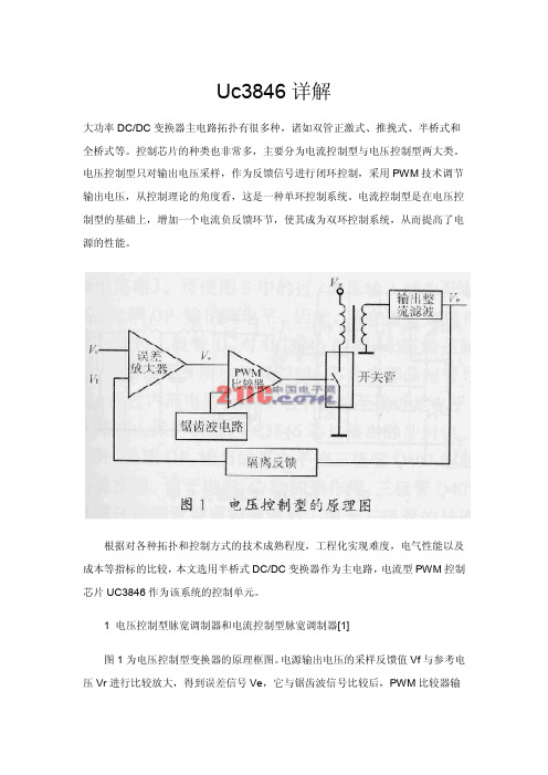
1 电压控制型脉宽调制器和电流控制型脉宽调制器[1]图1为电压控制型变换器的原理框图。
电源输出电压的采样反馈值Vf与参考电压Vr进行比较放大,得到误差信号Ve,它与锯齿波信号比较后,PWM比较器输出PWM控制信号,经驱动电路驱动开关管通断,产生高频方波电压,由高频变压器传输至副方,经整流滤波得到所需要的电压。
改变电压给定Vr,即可改变输出电压Vo。
图2为电流控制型变换器的原理框图。
恒频时钟脉冲置位R-S锁存器,输出高电平,开关管导通,变压器原边的电流线性增大,当电流在采样电阻Rs上的压降Vs达到Ve时,PWM比较器翻转,输出高电平,锁存器复位,驱动信号变低,开关管关断,直到下一个时钟脉冲使R-S锁存器置位。
电路就是这样逐个地检测和调节电流脉冲的。
当电源输入电压和/或负载发生变化时,两种控制类型的动态响应速度是不同的。
如果电压升高,则开关管的电流增长速度变快。
对电流控制型而言,只要电流脉冲一达到设定的幅值,脉宽比较器就动作,开关管关断,保证了输出电压的稳定。
对电压控制型而言,检测电路对电流的变化没有直接的反映,一直等到输出电压发生变化后才去调节脉宽,由于滤波电路的滞后效应,这种变化需要多个周期后才能表现出来,显然动态响应速度要慢得多,且输出电压的稳定性也受到一定的影响。
LTC1232 精密电源监控模块说明书

123sn1232 1232fasSYMBOL PARAMETER CONDITIONSMINTYP MAX UNITSV CC Supply Voltage● 4.555.5V V IH ST and PB RST Input High Level ●2V CC +0.3V V ILST and PB RST Input Low Level●–0.30.8VDC ELECTRICAL CHARACTERISTICSSYMBOL PARAMETER CONDITIONS MINTYP MAX UNITS I IL Input Leakage (Note 3)●–11µA I OH Output Current at 2.4V (Note 5)●–1–13mA I OL Output Current at 0.4V (Note 5)●26mAI CC Supply Current (Note 4)●0.52mA V CCTP V CC Trip Point TOL = GND ● 4.5 4.62 4.74 V V CCTP V CC Trip PointTOL = V CC●4.254.37 4.49 V V HYS V CC Trip Point Hysteresis 40mV V RSTRST Output Voltage at V CC = 1VI SINK = 10µA4200mVThe ● denotes the specifications which applyover the full operating temperature. V CC = full operating range.The ● denotes the specifications which apply over the full operatingtemperature. V CC = full operating range.SYMBOL PARAMETER CONDITIONSMIN TYP MAX UNITS t PB PB RST = V IL ●40ms t RST RESET Active Time ●2506101000ms t ST ST Pulse Width●20ns t RPD V CC Detect to RST and RST ●100ns t f V CC Slew Rate 4.75V–4.25V ●300µs t RPU V CC Detect to RST and RSTt R = 5µs●2506101000ms (Reset Active Time)t R V CC Slew Rate 4.25V–4.75V ●0nst TDST Pin Detect to RST and RST TD = GND ●60150250ms (Watchdog Time-Out Period)TD = Floating ●2506101000ms TD = V CC●50012002000ms C IN Input Capacitance 5pF C OUTOutput Capacitance5pFNote 1: Absolute Maximum Ratings are those values beyond which the life of a device may be impaired.Note 2: All voltage values are with respect to GND.Note 3: The PB RST pin is internally pulled up to V CC with an internal impedance of 10k typical. The TD pin has internal bias current.Note 4: Measured with outputs open.Note 5: The RST pin is an open drain output.The ● denotes the specifications which apply over the full operating temperature.V CC = full operating range.AC CHARACTERISTICSRECO E D ED OPERATI G CO DITIO SU U U U WW456Information furnished by Linear Technology Corporation is believed to be accurate and reliable. However, no responsibility is assumed for its use. Linear Technology Corporation makes no represen-tation that the interconnection of its circuits as described herein will not infringe on existing patent rights.7Linear Technology Corporation 1630 McCarthy Blvd., Milpitas, CA 95035-7417 (408) 432-1900 ● FAX: (408) 434-0507 ● LW/TP 1002 1K REV A • PRINTED IN USA © LINEAR TECHNOLOGY CORPORA TION 19928。
Agilent E363xA系列可编程DC电源说明书

Agilent E363xA SeriesProgrammable DC Power SuppliesData Sheet1981Reliable Power, Repeatable Results• Single and triple output• 80 W to 200 W output power • Dual range output(except E3631A)• Low noise and excellentregulation• Remote sensing(except E3631A)• Front and rear outputterminals(E3633A/34A only)• GPIB and RS-232 standard • Save and recall functions• Overvoltage protection,Overcurrent protection(except E3631A)Clean and stable power with programmability at an affordable priceAffordable programmable power supplies to meet your needsThe E363xA Series of programmable DC power supplies gives you the performance of the system power supplies at a decent price. All models provide clean power, excellent regula-tion and a fast transient response with built-in GPIB and RS-232 interfaces. The E363xA Series is designed to meet the requirements of the most demanding applications in R&D design verifications, production testing, and QA verifications with traditional quality and reliability which you can count on.Excellent performance you can trustWith the 0.01% load and lineregulation, the E363xA Series canmaintain a steady output when powerline and load changes occur. Thepower supplies specify both normalmode voltage/current noise andcommon mode current noise. Thelow normal mode noise specificationassures clean power for precisioncircuitry applications, and the lowcommon mode current provides isola-tion from power line current injection.Remote InterfaceIf you have an IEEE-488 card orRS-232 in a PC, these power supplieswill work for you. Every model comesequipped with both GPIB and RS-232as standard. All programming is donein easy-to-use SCPI (Standard Com-mands for Programmable Instruments).The user’s guide describes the processfor the first-time programmers.Front Panel OperationA knob and self-guiding keypads allowyou to set the output at your desiredresolution quickly and easily. Youcan store and recall for up to threecomplete setups using the internalnon-volatile memory. The output on/off button sets the output to zero.E3631A triple-output power supplyThis famous 80-watt triple outputsupply offers three independentoutputs: 0 to 6 V/5A, 0 to +25V/1Aand 0 to –25V/1A. The 6 V output iselectrically isolated from the ±25 Vsupply to minimize any interferencebetween circuits under test. The ±25 Voutputs can be set to track each other.E3632A/33A/34A single-outputdual range power suppliesThese single output power suppliesgive you the flexibility to select froma dual output range. The output loadis protected against overvoltageand overcurrent, which are easilymonitored and adjusted from the frontpanel and remote interface. Remotesensing is available to eliminate theerrors caused by voltage drops onthe load leads. The E3633A/34A offerfront and rear output terminals foreasy wiring.2Model NumberE3631AE3632A E3633A E3634A 123DC Output Rating (0 ºC to 40 ºC)0 to +6 V,0 to 5 A0 to +25 V,0 to 1 A0 to –25 V,0 to 1 A0 to 15 V/7 A or0 to 30 V/4 A0 to 8 V/20 A or0 to 20 V/10 A0 to 25 V/7 A or0 to 50 V/ 4 ALoad Regulation± (% of output + offset)< 0.01% + 2 mV < 0.01% + 250 μALine Regulation± (% of output + offset)< 0.01% + 2 mV < 0.01% + 250 μARipple and Noise (20 Hz to 20 MHz)Normal Mode Voltage< 350 μVrms/2 mVpp< 350 μVrms/3mVpp< 500 μVrms/ 3 mVpp Normal Mode Current< 2 mArms< 500 μArms< 2 mArmsCommon Mode Current< 1.5 μArmsAccuracy1 12 Months (25 ºC + 5 ºC), ± (% output + offset)ProgrammingVoltage0.1% + 5 mV0.05% + 20 mV0.05% + 10 mVCurrent0.2% + 10 mA0.15% + 4 mA0.2% + 10 mAReadback2Voltage0.1% + 5 mV0.05% + 10 mV0.05% + 5 mVCurrent0.2% + 10 mA0.15% + 4 mA0.15% + 5 mAResolutionProgram0.5 mV/0.5 mA 1.5 mV/0.1 mA 1 mV/0.5 mA 1 mV/1 mA 3 mV/0.5 mA Readback0.5 mV/0.5 mA 1.5 mV/0.1 mA0.5 mV/0.1 mA0.5 mV/1 mA 1.5 mV/0.5 mA Meter 1 mV/1 mA10 mV/1 mA 1 mV/1 mA 1 mV/1 mA (< 10A), 10 mA (¡ 10 A) Transient Response Less than 50 μsec for output to recover to within 15 mV following a change in output current from full load to half loador vice versaCommand ProcessingTime3< 50 msec< 100 msecOVP/OCPAccuracy± (% output + offset)N/A0.5% + 0.5 V/0.5% + 0.5 AActivation Time N/A 1.5 msec, OVP ¡ 3 V/< 10 msec, OVP < 3 V and OCP <10 msec Temperature Coefficient per ºC (% output + offset)Voltage0.01% + 2 mV0.01% + 3 mVCurrent0.02% + 3 mA0.02% + 0.5 mA0.02% + 3 mAStability, constant load & temperature ± (% of output + offset), 8 hrsVoltage0.03% + 1 mV0.02% + 2 mV0.02% + 1 mVCurrent0.1% + 3 mA0.05% + 1 mA0.1% + 1 mARemote Sense (max.voltage in each load lead)N/A 1 V0.7 VVoltage Programming Speed, to within 1% of total excursionUp Full Load11 msec50 msec50 msec95 msec80 msecNo Load10 msec20 msec20 msec45 msec100 msec Down Full Load13 msec 45 msec45 msec30 msec30 msecNo Load200 msec400 msec400 msec450 msec450 msecE3631A/32A/33A/34A Programmable DC Power Supply Specifications1 Accuracy specifications are valid after a 1-hour warm-up and calibration at 25 ºC.2 Accuracy refers to readback over GPIB and RS-232 or front panel with respect to actual output.3 Maximum time for output to change after receipt of commands.34Ordering Information E3630 Series Power Supplies E3631A 80-WattTriple Power Supply E3632A 120-WattSingle Power Supply E3633A/34A 200-Watt Single Power Supply Standard Shipped Accessories User’s & Service guide, Product Reference CD, AC power cord Power Options Opt. 0E3 230 Vac ± 10%Opt. 0EM 115 Vac ± 10%Opt. 0E9 100 Vac ± 10%Other OptionsOpt. 0L2 Extra manual sets Opt. 1CM Rackmount kit*Opt. UK6 Commercial calibration with test result data E3600A-100 Test lead kitModel Number E3631AE3632A E3633A E3634A123AC Input (47 Hz – 63 Hz)100 Vac ±10% (Opt 0E9)/115 Vac ±10% (Std)/230 Vac ±10% (0E3)Dimensions 213 x mm W x 133 mm H x 348 mm D(8.4 x 5.2 x 13.7 in)Weight 8.2 kg (18 lbs) net, 11 kg (24 lbs) shipping9.5 kg (21 lbs) net, 12 kg (26 lbs) shippingWarranty Three years for E363xA series power supplies Three months for standard shipped accessoriesProduct RegulationCertified to CSA 22.2 No. 231 (for E3631A), No. 1010.1 (for E3632A/33A/34A); conforms to IEC 1010-1; carries CE marks; complies with CISPR-11, Group 1, Class ARackmount Kits*Agilent E3631A/32A/33A/34A To rackmount two instruments side-by-sideLock-link Kit (P/N 5061-9694) Flange Kit (P/N 5063-9214)To rackmount one or two instruments in a sliding support shelfSupport Shelf (P/N 5063-9256) Slide Kit (P/N 1494-0015) required for support shelf* Rackmounting with 1CM or lock-link/flange kit requiresAgilent or customer support rails Agilent Support Rails-E3663ACLAN eXtensions for Instruments puts the power of Ethernet and the Web inside your test systems. Agilent is a founding member of the LXI consor-tium.Agilent Channel Partnersw w w /find/channelpartners Get the best of both worlds: Agilent’s measurement expertise and product breadth, combined with channel partner convenience.For more information on Agilent Tech-nologies’ products, applications or services, please contact your local Agilent office. The complete list is available at:/find/contactus Americas Canada (877) 894 4414 Brazil (11) 4197 3600Mexico 01800 5064 800 United States (800) 829 4444 Asia Pacific Australia 1 800 629 485China 800 810 0189Hong Kong 800 938 693India 1 800 112 929Japan 0120 (421) 345Korea 080 769 0800Malaysia 1 800 888 848Singapore 180****8100Taiwan 0800 047 866Other AP Countries (65) 375 8100 Europe & Middle East Belgium 32 (0) 2 404 93 40 Denmark 45 45 80 12 15Finland 358 (0) 10 855 2100France 0825 010 700* *0.125 €/minute Germany 49 (0) 7031 464 6333 Ireland 1890 924 204Israel 972-3-9288-504/544Italy 39 02 92 60 8484Netherlands 31 (0) 20 547 2111Spain 34 (91) 631 3300Sweden 0200-88 22 55United Kingdom 44 (0) 118 927 6201For other unlisted countries:/find/contactus(BP-3-1-13)Product specifications and descriptions in this document subject to change without notice.© Agilent Technologies, Inc. 2013Published in USA, April 18, 20135968-9726ENAdvancedTCA ® Extensions for Instrumentation and Test (AXIe) is an open standard that extends the AdvancedTCA for general purpose and semiconductor test. Agilent is a founding member of the AXIe consortium.PCI eXtensions for Instrumentation (PXI) modular instrumentationdelivers a rugged, PC-based high-per-formance measurement and automa-tion system./find/myagilent A personalized view into the information most relevant to you.myAgilentmy /qualityQuality Management SystemQuality Management Sys ISO 9001:2008DEKRA Certified /find/AdvantageServices Accurate measurements throughout the life of your instruments.Agilent Advantage ServicesThree-Year Warranty/find/ThreeYearWarranty Agilent’s combination of product reliability and three-year warranty coverage is another way we help you achieve your business goals: increased confidence in uptime, reduced cost of ownership and greater convenience.。
SC34063L(DC-DC变换器控制IC)1.2A
SC34063L(文件编号:SC34063L(文件编号:S&CIC0887)DC-DC变换器控制IC 五、极限参数六、电气参数(除非特别说明,VDD=5V,Ta=0~70℃)七、工作原理由于内置有大电流的电源开关,SC34063L能够控制的开关电流达到1.2A。
内部线路包含有参考电压源、振荡器、转换器、逻辑控制线路和开关晶体管。
参考电压源是温度补偿的带隙基准源。
振荡器的振荡频率由3脚的外接定时电容决定。
开关晶体管由比较器的反向输入端和与振荡器相连的逻辑控制线路置成ON,并由与振荡器输出同步的下一个脉冲置成OFF。
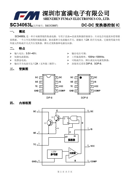
SC34063L(文件编号:S&CIC0887)DC-DC变换器控制IC 八、设计规范表SAT ONV F整流二极管正向压降t OFF输出开关管关闭时间九、电路原理内部框图中所表示的电路解释如下:振荡器通过恒流源对外接在CT管脚(3脚)上的定时电容不断地充电和放电,以产生振荡波形。
充电和放电电流都是恒定的,所以振荡频率仅取决于外接定时电容的容量。
与门的C输入端在振荡器对外充电时为高电平,D 输入端在比较器的输入电平低于阈值电平时为高电平。
当C和D输入端都变成高电平时,触发器被置为高电平,输出开关管导通。
反之,当振荡器在放电期间,C输入端为低电平,触发器被复位,使得输出开关管处于关闭状态。
电流限制SI检测端(5脚)通过检测连接在V+和5脚之间电阻上的压降来完成功能。
当检测到电阻上的电压降接近超过300mV时,电流限制电路开始工作。
这时通过CT管脚(3脚)对定时电容进行快速充电,以减少充电时间和输出开关管的导通时间,结果是使得输出开关管的关闭时间延长。
SC34063L(文件编号:。
TS34063 DC-DC 转换器控制器数据手册说明书
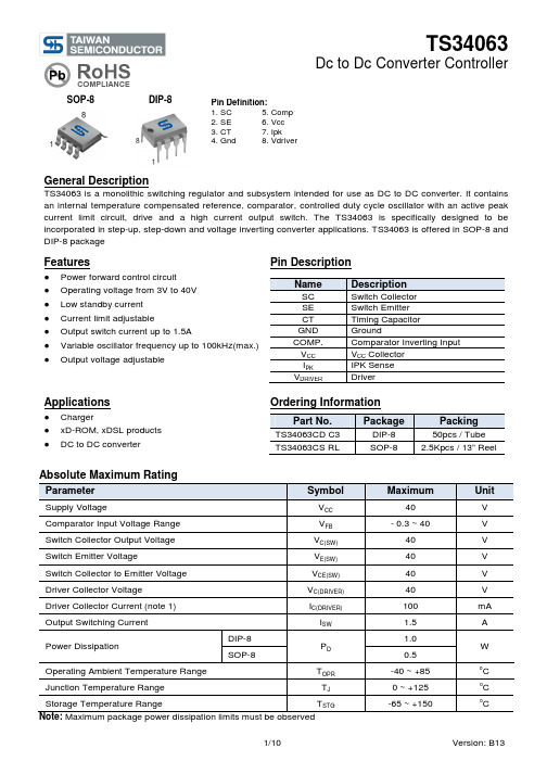
SOP-8DIP-8General DescriptionTS34063 is a monolithic switching regulator and subsystem intended for use as DC to DC converter. It containsan internal temperature compensated reference, comparator, controlled duty cycle oscillator with an active peak current limit circuit, drive and a high current output switch. The TS34063 is specifically designed to be incorporated in step-up, step-down and voltage inverting converter applications. TS34063 is offered in SOP-8 and DIP-8 packageFeatures● Power forward control circuit ● Operating voltage from 3V to 40V ● Low standby current ● Current limit adjustable● Output switch current up to 1.5A● Variable oscillator frequency up to 100kHz(max.) ● Output voltage adjustablePin DescriptionNameDescriptionSC Switch Collector SE Switch Emitter CT Timing Capacitor GND GroundCOMP. Comparator Inverting Input V CC V CC Collector I PK IPK Sense V DRIVERDriverApplications● Charger● xD-ROM, xDSL products ● DC to DC converterOrdering InformationPart No.PackagePackingTS34063CD C3 DIP-8 50pcs / Tube TS34063CS RLSOP-82.5Kpcs / 13” ReelAbsolute Maximum RatingParameterSymbolMaximumUnitSupply VoltageV CC 40 V Comparator Input Voltage Range V FB - 0.3 ~ 40V Switch Collector Output Voltage V C(SW) 40 V Switch Emitter VoltageV E(SW) 40 V Switch Collector to Emitter Voltage V CE(SW) 40 V Driver Collector Voltage V C(DRIVER) 40 V Driver Collector Current (note 1) I C(DRIVER) 100 mA Output Switching Current I SW 1.5 A Power DissipationDIP-8 P D 1.0 WSOP-80.5 Operating Ambient Temperature Range T OPR -40 ~ +85 oC Junction Temperature RangeT J0 ~ +125 o C Storage Temperature Range T STG -65 ~ +150oCNote: Maximum package power dissipation limits must be observedPin Definition:1. SC 5. Comp2. SE 6. Vcc3. CT 7. Ipk4. Gnd 8. VdriverElectrical Characteristics(V CC =5V, Ta =25o C; unless otherwise noted.)Parameter Symbol Test Conditions Min Typ Max Unit Oscillator (OSC)Frequency F OSC C T = 1nF, Vpin5= 0V 24 33 42 KHz Charge Current I CHARGE V CC = 5V ~ 40V 24 30 42 uA Discharge Current I DISCHARGE V CC = 5V ~ 40V 140 200 260 uADischarge to Charge current ratio I DISCHARGE/ I CHARGEPin7 to V CC 5.2 6.5 7.5 --Current Limit Sense Voltage V IPK(SENSE)I DISCHARGE = I CHARGE250 -- 350 mV Output switch (note1)Saturation Voltage V CE(SAT)I SW= 1A, pin1, 8 connected -- 1.0 1.3 V Saturation Voltage V CE(SAT)I SW= 1A, Id=50mA -- 0.45 0.7 V DC current gain H FE I SW = 1A, V CE= 0.5V 50 75 -- -- Collector off-state current I C(OFF)V CE = 40V -- 0.01 100 uA ComparatorThreshold Voltage V REF 1.225 1.25 1.275 V Line regulation REG LINE V CC = 3V ~ 40V -- -- 6 mV Total deviceSupply Current I CC V CC = 5V ~ 40V, C T = 1nF,pin7= V CC, pin5> V TH,pin2=Gnd, remaining pinsopen-- 3 5 mANotes1: Low duty cycle pulse techniques are used during test to maintain junction temperature as close to ambient temperature as possibleNote 2:If the output switch is driven into hard saturation (non-Darlington configuration) at low switch currents (<=300mA) and high driver currents (>=30mA), it may take up to 2uS for it to come out of saturation. This condition will shorten the off time at frequencies >= 30KHz, and is magnified at high temperature. This condition does not occur with a Darlington configuration, since the output switch cannot saturate. If a non-darlington configuration is used, the following output drive condition is recommended: Forced Bata of output switch: Ic output / (Ic driver – 7mA*) >= 10* The 100ohm resistor in the emitter of the driver divide requires about 7mA before the output switch conducts.Block DiagramElectrical Characteristics CurveFig 1. Output Switch ON-OFF TIME vs.Oscillator Timing CapacitorFig 2. Timing Capacitor Wave FormFig 3. Oscillator Frequency vs. Timing CapacitorFig 4. Standby Supply Current vs. Supply VoltageFig 5. Current Limit Sense Voltage vs. TemperatureTypical Application CircuitTest Conditions ResultsLine Regulation V IN= 8V~16V, Io= 175mA 30mV = ± 0.05%Load Regulation V IN = 12V, Io= 75mA to 175mA 10mV = ± 0.017%Output Ripple V IN =12V, Io= 175mA 400mVppEfficiency V IN =12V, Io= 175mA 87.7%Output Ripple with Optional Filter V IN =12V, Io= 175mA 40mVppFigure 7. Step Up ConverterTypical Application Circuit (Continue)Test Conditions ResultsLine Regulation V IN= 15V~25V, Io= 500mA 12mV = ±12%Load Regulation V IN = 25V, Io= 50mA to 500mA 3mV = ±0.03%Output Ripple V IN =25V, Io= 500mA 120mVppShort Circuit Current V IN =25V, R L= 0.1mΩ 1.1AEfficiency V IN =25V, Io= 500mA 83.7%Output Ripple with Optional Filter V IN =25V, Io= 500mA 40mVppFigure 9. Step Down ConverterTypical Application Circuit (Continue)Test Conditions ResultsLine Regulation V IN= 4.5V~6V, Io= 100mA 3mV = ±120.012%Load Regulation V IN = 5V, Io= 10mA to 100mA 0.022V = ±0.09%Output Ripple V IN =5V, Io= 100mA 500mVppShort Circuit Current V IN =5V, R L= 0.1Ω910mAEfficiency V IN =5V, Io= 100mA 62.2%Output Ripple with Optional Filter V IN =5V, Io= 100mA 70mVppFigure 11. Voltage Inverting ConverterDesign Formula TableTerms and DefinitionsVsat = Saturation Voltage of the output switch.Vf= Forward Voltage drop of the rectifier.The following power supply characteristics must be chosen:Vin= Normal input voltageVout: Desied Output voltage, |Vout| =1.25 (1+R2 / R1)Iout : Desired output current.fmin : Minimum desired output switching frequency at the selected values for Vin and Io.Vripple(p-p): Desired peak-to-peak output ripple voltage. in practice, the calculated capacitor value will need to be increased due to its equivalent series resistance and board layout. The ripple voltage should be kept toa low value since it will directly affect the line and load regulation.SOP-8 Mechanical DrawingMarking DiagramY = Year Code M = Month Code(A =Jan, B =Feb, C =Mar, D =Apl, E =May, F =Jun, G =Jul, H =Aug, I =Sep, J =Oct, K =Nov, L =Dec) L = Lot CodeSOP-8 DIMENSION DIM MILLIMETERS INCHES MIN MAX MIN MAX. A 4.80 5.00 0.189 0.196 B 3.80 4.00 0.150 0.157 C 1.35 1.75 0.054 0.068 D 0.35 0.49 0.014 0.019 F 0.40 1.25 0.016 0.049G 1.27BSC 0.05BSC K 0.10 0.25 0.004 0.009 M 0º 7º 0º 7º P 5.80 6.20 0.229 0.244 R0.25 0.50 0.010 0.019DIP-8 Mechanical DrawingMarking DiagramY = Year Code M = Month Code(A =Jan, B =Feb, C =Mar, D =Apl, E =May, F =Jun, G =Jul, H =Aug, I =Sep, J =Oct, K =Nov, L =Dec) L = Lot CodeDIP-8 DIMENSION DIM MILLIMETERS INCHES MIN MAX MIN MAX A 9.07 9.32 0.357 0.367 B 6.22 6.48 0.245 0.255 C 3.18 4.45 0.125 0.135 D 0.35 0.55 0.019 0.020 G 2.54 (typ) 0.10 (typ) J 0.29 0.31 0.011 0.012 K 3.25 3.35 0.128 0.132 L 7.75 8.00 0.305 0.315M- 10o - 10oNoticeSpecifications of the products displayed herein are subject to change without notice. TSC or anyone on its behalf, assumes no responsibility or liability for any errors or inaccuracies.Information contained herein is intended to provide a product description only. No license, express or implied, to any intellectual property rights is granted by this document. Except as provided in TSC’s terms and conditions of sale for such products, TSC assumes no liability whatsoever, and disclaims any express or implied warranty, relating to sale and/or use of TSC products including liability or warranties relating to fitness for a particular purpose, merchantability, or infringement of any patent, copyright, or other intellectual property right.The products shown herein are not designed for use in medical, life-saving, or life-sustaining applications. Customers using or selling these products for use in such applications do so at their own risk and agree to fully indemnify TSC for any damages resulting from such improper use or sale.。
DC转换器MC34063的应用

低成本DC/DC转换器34063的应用34063由于价格便宜,开关峰值电流达1.5A,电路简单且效率满足一般要求,所以得到广泛使用。
在ADSL 应用中,34063的开关频率对传输速率有很大影响,在器件选择及PCB设计时需要仔细考虑。
线性稳压电源效率低,所以通常不适合于大电流或输入、输出电压相差大的情况。
开关电源的效率相对较高,而且效率不随输入电压的升高而降低,电源通常不需要大散热器,体积较小,因此在很多应用场合成为必然之选。
开关电源按转换方式可分为斩波型、变换器型和电荷泵式,按开关方式可分为软开关和硬开关。
斩波型开关电源斩波型开关电源按其拓扑结构通常可以分为3种:降压型(Buck)、升压型(Boost)、升降压型(Buck-boost)。
降压型开关电源电路通常如图1所示。
图1中,T为开关管,L1为储能电感,C1为滤波电容,D1为续流二极管。
当开关管导通时,电感被充磁,电感中的电流线性增加,电能转换为磁能存储在电感中。
设电感的初始电流为iL0,则流过电感的电流与时间t的关系为:iLt= iL1 (Vi-Vo-Vs)t/L,Vs为T的导通电压。
当T关断时,L1通过D1续流,从而电感的电流线性减小,设电感的初始电流为iL1,则则流过电感的电流与时间t的关系:iLt=iL1-(Vo Vf)t/L,Vf为D1的正向饱和电压。
图1 降压型开关电源基本电路34063的特殊应用● 扩展输出电流的应用DC/DC转换器34063开关管允许的峰值电流为1.5A,超过这个值可能会造成34063永久损坏。
由于通过开关管的电流为梯形波,所以输出的平均电流和峰值电流间存在一个差值。
如果使用较大的电感,这个差值就会比较小,这样输出的平均电流就可以做得比较大。
例如,输入电压为9V,输出电压为3.3V,采用220μH 的电感,输出平均电流达到900mA,峰值电流为1200mA。
单纯依赖34063内部的开关管实现比900mA更高的输出电流不是不可以做到,但可靠性会受影响。
低成本DCDC转换器34063的应用

低成本DC/DC转换器34063的应用(图)斩波型开关电源斩波型开关电源按其拓扑结构通常可以分为3种:降压型(Buck)、升压型(Boost)、升降压型(Buck-boost)。
降压型开关电源电路通常如图1所示。
图1中,T为开关管,L1为储能电感,C1为滤波电容,D1为续流二极管。
当开关管导通时,电感被充磁,电感中的电流线性增加,电能转换为磁能存储在电感中。
设电感的初始电流为iL0,则流过电感的电流与时间t的关系为:iLt= iL1+(Vi-Vo-Vs)t/L,Vs为T的导通电压。
当T关断时,L1通过D1续流,从而电感的电流线性减小,设电感的初始电流为iL1,则则流过电感的电流与时间t 的关系:iLt=iL1-(Vo+Vf)t/L,Vf为D1的正向饱和电压。
图1降压型开关电源基本电路34063的特殊应用● 扩展输出电流的应用DC/DC转换器34063开关管允许的峰值电流为1.5A,超过这个值可能会造成34063永久损坏。
由于通过开关管的电流为梯形波,所以输出的平均电流和峰值电流间存在一个差值。
如果使用较大的电感,这个差值就会比较小,这样输出的平均电流就可以做得比较大。
例如,输入电压为9V,输出电压为 3.3V,采用220μH的电感,输出平均电流达到900mA,峰值电流为1200mA。
单纯依赖34063内部的开关管实现比900mA更高的输出电流不是不可以做到,但可靠性会受影响。
要想达到更大的输出电流,必须借助外加开关管。
图2和图3是外接开关管降压电路和升压电路。
图2升压型达林顿及非达林顿接法图3 降压型达林顿及非达林顿接法采用非达林顿接法,外接三极管可以达到饱和,当达到深度饱和时,由于基区存储了相当的电荷,所以三极管关断的延时就比较长,这就延长了开关导通时间,影响开关频率。
达林顿接法虽然不会饱和,但开关导通时压降较大,所以效率也会降低。
可以采用抗饱和驱动技术,图4所示,此驱动电路可以将Q1的 Vce保持在 0.7V以上,使其导通在弱饱和状态。
MC34063产品说明书
DC/DC变换器控制电路34063产品说明书1、简介34063单片双极型线性集成电路,是专用于直流-直流变换器的控制芯片。
片内包含温度补偿带隙基准源、占空比周期控制器、功率驱动和大电流输出开关,最大峰值电流可达1.5A。
特点:○1工作电压范围宽,可在3.0V~40V的电压下工作;○2短路电流限制保护功能;○3静态功耗低;○4输出峰值电流可达1.5A(无外接三极管);○5输出电压可调;;○6工作振荡频率从100Hz到100KHz;○7可构成升压,降压和反向电源变换器。
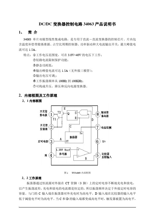
2.内部框图及工作原理2.1内部框图图1 TY34063内部框图2.2工作原理振荡器通过恒流源对外接在CT管脚(3脚)上的定时电容不断地充电和放电,以产生振荡波形,充电和放电的电流都是恒定的,所以振荡频率决定于外接定时电容的容量。
与门的C输入端在振荡器对外充电时为高电平,D输入端在比较器的输入电平低于阈值电平时为高电平。
当C和D的输入端都变成高电平时,触发器被置为高电平,输出开关管导通。
反之,到振荡器在放电期间,C输入端为低电平,触发器被复位,使得输出开关管处于关闭状态。
电流限制检测端Is通过检测连接在V+和7脚之间电阻上的压降来完成功能。
当检测到电阻上的电压降接近超过300mV时,电流限制电路开始工作。
这时通过CT管脚(3脚)对定时电容进行快速充电,以减少充电时间和输出开关管的导通时间,结果是使得输出开关管的开关时间延长。
3.参数及测试条件:3.1极限参数表1.极限参数3.2电参数表2. 电参数(除非特殊说明:V+=5V,Ta=25℃)4.典型应用电路:图2 .升压变换器图3 .降压变换器图4 .反向变换器图5 .升压变换器(大电流)图6 .降压变换器(大电流)5.封装形式:封装采用DIP8和SOP8两种封装形式,如下图所示。
图7 DIP8封装图8 SOP8封装。
TI德州DCDC管理IC
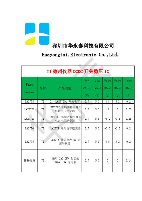
Capacitor StepDown
Regulator
LM2757 LM2772 TL7660
具有输出(停机时)的开
TI
2.7
关电容器升压稳压器
低纹波开关电容器降压稳
TI
2.7
压器
TI
CMOS 电压转换器
1.5
5.5 4.87 5.13 0.18
5.5 1.2 1.2 10 -1.5 -10
0.15 0.1
LM2663
TI 开关电容器电压转换器 1.5 5.5 -5.5 11
0.2
LM2662
TI 开关电容器电压转换器 1.5 5.5 -5.5 11
0.2
LM2660
TI 开关电容器电压转换器 1.5 5.5 -5.5 11
0.1
LT1054
具有稳压器的带开关电容
TI
3.5 15 -1.25 -15 0.1
单节至 3.0V/3.3V、20mA
TPS60302 TI
0.9 1.8 3.3 3.3 0.04
双路输出、高效充电泵
单节至 3.0V/3.3V、20mA
TPS60303 TI
0.9 1.8 3
双路输出、高效充电泵
3 0.04
单节至 3.3V 20mA 超低
TPS60310 TI
0.9 1.8 3.3 3.3 0.02
深圳市华永泰科技有限公司 Huayongtai.Electronic Co.,Ltd.
TI 德州仪器 DCDC 开关稳压 IC
Part number
LM2775 LM27762 LM27761
Vin Vin Vout Vout Iout
品牌
产品功能
LTC3803/-3/-5MP:反激式控制器
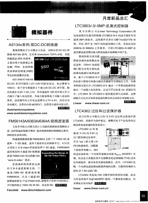
L C3 0 / / MP 反 激பைடு நூலகம்式 控 制 器 T 8 3一 35 :
凌 力 尔 特 公 司 (ie r e h oo yCop rt n 推 Ln a T c n lg roa o ) 出 电流模式 反激式 控制 器 L C3 0 / / T 8 3- 一 3 5的高可 靠性 军用 温度 ( ) MP 级版 本 。这 些器 件 采 用 6引脚 T i OT M 封 hn S T
并可提供混合 18 i D和 S ,或全部 S 。 00H D D 舀岛目圃
Fa r ichi WW W.aic l l d f r hidse Lcom m
实现电压反向保护。 匿囫圈
lne i ar
w ww.i arcom . n 1ne . c
世 界 电子 元器 件 2 . a 01 7 ec.cc 0 e ntom
飞兆半导体公 司现 为设计人 员提供视频 滤波器 解决方
LC 3 2 T 4 6 ,该器件 为保 护低压 、便携 式 电子 产品免 受 电压
瞬态和 电流浪 涌的损害而设计 。
L C 3 2运 用 准 T 46
案, 支持更高的视频分辨率 、 移动视频和新 的视频输 出要求 ,
同时优 化系统功耗 。 四通 道视频滤 波器 F 6 6 A支持 三个 1 8 i MS 3 4 0 0 HD通
装 ,可 在 .5 5 ℃至 1 0 5 ℃的结 温范 围 内工作 。具 备恒 定的 2 0H 0 k z或 3 0 H 0 k z工 作 频 率 ,可 使 L C3 O / / MP在 T 8 3- . 35
宽负载 电流范围 内最大 限度地 减少低频噪声的产生。
主要 应 用 于包 括 笔记 本
UC3843应用电路

UC3843应用电路——15W三路输出DC/DC模块电源设计(1)简介:UC3843应用电路——15W三路输出DC/DC模块电源设计本文介绍了一种UC3843控制的小功率多路DC/DC模块电源的详细设计过程,重点讨论了多路输出模块电源设计与 ...关键字:UC3843DC/DC模块电源设计本文介绍了一种UC3843控制的小功率多路DC/DC模块电源的详细设计过程,重点讨论了多路输出模块电源设计与单路输出的不同,详细介绍了DC/DC模块电源中常用的新型芯片UC3843的外围电路参数的设计,给出了多路输出模块电源中变压器和耦合电感的设计过程及满足各项性能指标应注意的各种问题。
关键词:DC/DC变换器;多路输出;UC3843; 耦合电感引言DC/DC模块已被广泛应用于铁路通信、微波通讯、工业控制、船舶电子、航空电子、地面雷达、消防设备和医疗器械教学设备等诸多领域,其中有许多应用场合需要多路输出,如在单片机智能控制器中,单片机供电需要5V,而运放通常需要12V。
在设计多路输出时,有许多地方和单路输出不同,既要考虑变压器管脚限制、多副边变压器设计、各路的稳压电路实现,又要考虑每路轻载及满载的负载调整率,以及负载的交叉调节特性等。
本文将通过一个给单片机智能控制器供电的15W三路模块电源的设计实例来详细说明多路输出模块电源的设计。
图1多路输出开关电源原理图模块电源的工作原理本文针对单片机主板供电电源所设计的多路输出开关电源如图1所示,其中电感L201、L202、L203是耦合电感,L204是偏置绕组,由于变压器管脚限制,取自耦合电感。
电源工作原理如下:电路采用单端正激变换电路,当变换器接通电源时,输入直流电压经由电阻、12V稳压管D601和三极管Q601、Q602组成的电路稳压降压后, 启动UC3843进入正常工作,偏置绕组L204的供电电路开始工作,输出经A4和C601整流及滤波后输出12V电压,高于自供电电压,使二极管A4反偏,启动电路停止工作。
34063中文资料

34063中文资料2009-11-04 23:041. MC34063 DC/DC变换器控制电路简介:MC34063是一单片双极型线性集成电路,专用于直流-直流变换器控制部分。
片内包含有温度补偿带隙基准源、一个占空比周期控制振荡器、驱动器和大电流输出开关,能输出1.5A的开关电流。
它能使用最少的外接元件构成开关式升压变换器、降压式变换器和电源反向器。
特点:*能在3.0-40V的输入电压下工作*短路电流限制*低静态电流*输出开关电流可达1.5A(无外接三极管)*输出电压可调*工作振荡频率从100HZ到100KHZ2.MC34063引脚图及原理框图3 MC34063应用电路图:3.1 MC34063大电流降压变换器电路3.2 MC34063大电流升压变换器电路3.3 MC34063反向变换器电路3.4 MC34063降压变换器电路3.5 MC34063升压变换器电路================================================================MC34063 电路原理管脚(3 脚)上的定时电容不断地充电和放电振荡器通过恒流源对外接在CT以产生振荡波形。
充电和放电电流都是恒定的,振荡频率仅取决于外接定时电容的容量。
与门的C 输入端在振荡器对外充电时为高电平,D 输入端在比较器的输入电平低于阈值电平时为高电平。
当C 和D输入端都变成高电平时触发器被置为高电平,输出开关管导通;反之当振荡器在放电期间,C 输入端为低电平,触发器被复位,使得输出开关管处于关闭状态。
电流限制通过检测连接在V和CC5 脚之间电阻上的压降来完成功能。
当检测到电阻上的电压降接近超过300 mV管脚(3 脚) 对定时电容进行快速充电时,电流限制电路开始工作,这时通过CT以减少充电时间和输出开关管的导通时间,结果是使得输出开关管的关闭时间延长。
带隔离输出的DC-DC变换电路方案电路原理电路原理如图2 所示,该电路是在MC34063典型的降压电路上,用开关变压器取代自感线圈实现的。
Linear 推出电流模式、固定频率升压型 DC-DC 转换器 LT3579
Linear 推出电流模式、固定频率升压型DC/DC 转
换器LT3579
加利福尼亚州米尔皮塔斯(MILPITAS, CA) – 2010 年 6 月 4 日–凌力尔特公司(Linear Technology Corporation) 推出电流模式、固定频率升压型DC/DC 转换器LT3579,该器件具有面向输出短路、输入/输出过压、以及过热情况的集成故障保护功能。
LT3579 含有两个集成的42V 开关,其中一个是 3.4A 主开关,另一个是 2.6A 从开关,这两个开关可以连接到一起以实现6A 的总电流。
LT3579 在 2.5V 至16V 的输入电压范围内工作,瞬态保护高达40V,从而非常适用于采用单节锂离子电池、汽车输入等各种输入
源的应用。
因为LT3579 可以配置为升压、SEPIC 或负输出转换器,所以它适用于很多本机电源设计。
该器件的4mm x 5mm QFN 封装(或TSSOP- 20E) 和纤巧外部组件可确保非常紧凑的占板面积,同时能最大限度地降低解决方案成本。
LT3579 的0.25V (连接到一起为 5.5A) 低VCESAT 开关提供高达90% 的效率。
两个开关组合并在5V 输入时,LT3579 可在12V 时提供高达1.7A 电流或在-12V 时提供 1.2A 电流。
就高压输出而言,LT3579 的从开关可实现大功率充电泵拓扑,这种拓扑效率非常高,且需要极少的外部组
件。
LT3579 的开关频率可以通过单个电阻器设定,或同步至一个200kHz 至 2.5MHz 的外部时钟,从而最大限度地减小了外部组件尺寸,并避开了“噪声关键”频段。
欠压闭锁(UVLO) 是用户可调的,以实现最佳系统性能。
CW34063CP
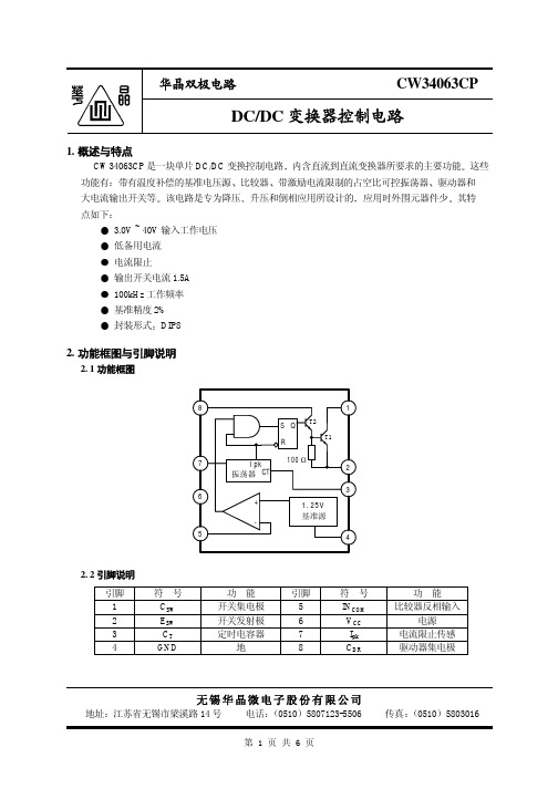
1
88 H 2
L 3
4
1500 pF
CO 1000 F
+
Vout -12V/100mA
1.0 H
Vout
100 F +
8
7 Rsc
6 Vin
5
CW34063CP CW34063CP
1 8
2
Vout
7
+
Rsc
3
6
Vin
4 5
PNP1
1
Vout
2
3
+
4
第5页共6页
华晶双极电路
5. 3 应用线路 3
CW34063CP
功能
引脚
开关集电极
5
开关发射极
6
定时电容器
7
地
8
符号 INCOM VCC
Ipk CDR
功能 比较器反相输入
电源 电流限止传感 驱动器集电极
无锡华晶微电子股份有限公司
地址 江苏省无锡市梁溪路 14 号 电话 0510 5807123-5506
第1页共6页
传真 0510 5803016
华晶双极电路
CW34063CP
定时电容波形
振荡电压 V
输出开关时间 ton-toff ( S)
10
t on
toff
1.0 0 0.02 0.1 0.2
1.0 2.0
10
振荡定时电容 CT (nF)
Vcc=5.0V Pin7=Vcc Pin2=Gnd
Pins1,5,8开路 CT=1.0nF Ta=25
10 S/DIV
20mV/DIV
工作环境温度
Tamb
采用MC34063芯片的DCDC电源变换控制器设计.

采用MC34063芯片的DC-DC电源变换控制器设计摘要:本文介绍了一种采用MC34063芯片的DC-DC电源变换控制器的电源电路设计。
它提供的直流输出不仅与供电电源共地,而且有两组与供电电源隔离。
实验室长期试运行表明,各项指标均可满足数字与模拟混合电路对电源的要求,没有跳码现象,检测精度不低于0.1%。
关键词:电源电路;DC-DC 变换;隔离电源在工业生产过程测控场合,出于安全的考虑,很多安装于现场的测量控制装置或测控网络的底层节点设备都采用低压直流供电。
这些装置或设备内部的硬件电路常常是基于微处理器的模拟电路与数字电路的混合硬件电路系统,需要多组直流电源为其数字电路部分与模拟电路部分分别供电。
为了取得良好的系统稳定性与测量精度,一般要求数字与模拟电路的供电电源相互隔离或一点连接。
使用多路输出电源是解决这一问题的有效途径。
早期制作多路输出电源,人们总是把几个不同的DC-DC变换器组装起来,这种方式的电路设计简单,但会加大成本,增加供电系统的体积、重量,并且有难以克服的拍频干扰,在输出电压上出现各种振荡频率之差的纹波电压。
因此开关电源的多路输出技术越来越受到人们的关注,因为它只用一个DC-DC变换器,输出电压的纹波具有相同的频率,不会发生拍频干扰。
目前多路输出变换器有3种常用的电路形式:独立滤波电感的多绕组DC-DC变换器,耦合电感的多绕组DC-DC变换器,磁放大器二次稳压的多绕组DC-DC变换器。
虽然使用多路输出变换器模块比组装几个不同DC-DC变换器电路效率高,成本降低,但是对于小型、小功率、低压控制模块来说还不是最佳选择。
本文基于多路输出变换技术,采用MC34063 控制芯片,使用少量的外围元件,设计了一种新型、简单、实用的多路输出电路,能为数字电路和模拟电路同时供电,并使两者相互隔离。
在笔者所查阅的文献中还没有看见类似的设计方法。
MC34063 性能简介电路的核心元件是MC34063 ,它是一种单片双极型线性集成电路,专用于DC-DC直流/直流变换器控制部分,片内包含有温度补偿带隙基准源、一个占空比可控的振荡器和大电流输出开关,能输出1.5A的开关电流。
模拟IC/电源管理

模拟IC/电源管理
佚名
【期刊名称】《电子产品世界》
【年(卷),期】2013(20)2
【摘要】TI超低功耗降压转换器加速无电池供电应用德州仪器推出业界最低功耗DC/DC降压转换器TPS62736,与其他器件相比可将终端应用可使用的采集能量提升达70%.该超低功耗电路可实现务种应用的无电池供电.如无线传感器网络、监控系统、烟雾探测器、可佩戴医疗设备以及移动附件等。
【总页数】1页(P86-86)
【关键词】电源管理;模拟IC;无线传感器网络;降压转换器;电池供电;超低功
耗;DC;DC;低功耗电路
【正文语种】中文
【中图分类】TN86
【相关文献】
1.模拟IC/电源管理 [J],
2.专注高性能模拟IC,实现电源管理IC快速增长 [J], 王丽英
3.聚集电源管理IC——电源管理IC如影随形各大芯片厂商戮力而为 [J], 无
4.模拟IC/电源管理 [J],
5.模拟IC/电源管理 [J],
因版权原因,仅展示原文概要,查看原文内容请购买。
