gmg_axis2
哈斯自动化GM-2大型平台3轴机器人铣制说明书
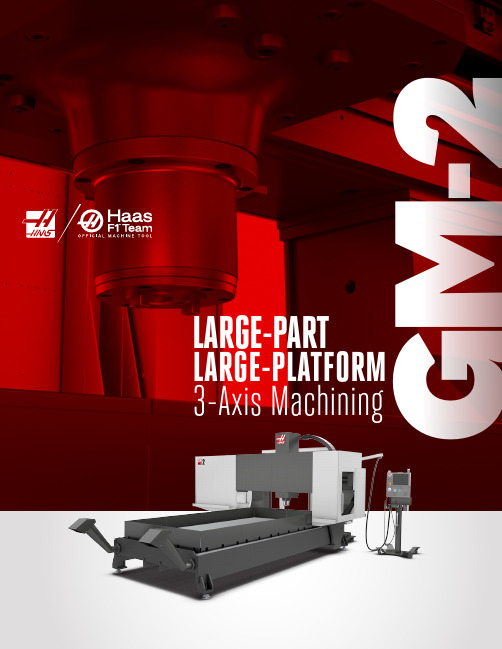
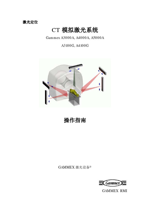
G M -2LARGE-PARTLARGE-PLATFORM 3-Axis MachiningHaas Automation, Inc.Large-Part, Large-Platform 3-axis MachiningThe GM-2 is a heavy-duty, 3-axis gantry mill designed for large-part machining, such as airframe components, large plates, and long extrusions. The machine’s rigid steel construction provides a very stable cutting platform, anda 1" thick aluminum table is standard. A traveling guard protects the operator from chips and coolant, and keeps the workspace clean.Dual Chip Augers while compressing them and wringing out the coolant. Ideal for both short runs and high-production environments, eliminating the downtime required for manual chip removal.to the cutting edge during machining operations. Increases tool life, allows for higher cutting speeds, and improves surface quality.Bring your machine tolife with the spindle that suits your needs.10,000-rpm Spindle 40 taper, 30 hp vector drive, inline direct-drive.15,000-rpm Spindle 40 taper, 30 hp vector drive, inline direct-driveNow with more X, Y , Z travels, andthe table space you need.GET MOREROOMTO T AKE ON LARGE P ARTSCOOLANT & CHIP MANAGEMENTMORE OPTIONS TO SUITYOUR SPECIFICA TRAVELS X Axis Y Axis Z AxisSpindle Nose to Table (~ max) Spindle Nose to Table (~ min) SPINDLE Max Rating Max Speed Max Torque Drive System TaperTABLELength 144" Length (Work Area) Thickness 1.0" Max Weight on Table (evenly distributed) Between Columns TOOL CHANGER Type / Capacity Max Tool Diameter (full) Max Tool Diameter (adjacent empty) Max Tool Length (from gage line ) Max Tool Weight 12 lb FEEDRATES Max Cutting 800 ipm Rapids on X 800 ipm Rapids on Y 2100 ipm Rapids on X1100 ipmDual-Ballscrew Drive SystemST ABILITY TWICE THE TORQUE Dual-Ballscrew Drive SystemTaking on those large parts needs greater stability. The GM-2’s dual-ballscrew design means more rigidity and power, for more accurate cutting and repeatability.Get your machine status notifications anywhere, on any device! The Haas Control has the ability to send you, and others you designate, email notifications about the operating status of your Haas machine. Set up is fast and easy through the MyHaas Portal and .HaasDrop is a fast and convenient method for sending images, videos, and even program files from a mobile device directly to a Haas NextGen Control. Download the free app, and start transferring files directly to the Haas control.MAKE THE CONNECTION WITH HAASCONNECTHAAS DROPMYHAAS MACHINE DET AILS P AGE View detailed information about your machines, including serial numbers,build dates, warranty start/end dates, product details, and machine option details. Sign up now at /myhaasFind out about the latest upgradesavailable for your machine, order parts, and quickly access service guides, manuals, and videos.Up-to-the-minute live eventtracking with HaasConnect remote monitoring.View detailed information about your machine, including serial number, machine build date, and warranty start /end dates.See how your machine isconfigured, with a detailed list of every option installed.MYHAAS Y OUR NEW FLEET MANAGEMENTHaas Automation, Inc. | | 800-331-6746 | Made in U.S.A.Specifications subject to change without notice. Not responsible for typographical errors. Machines shown with optional equipment.Actual product appearance may differ. Pricing subject to change without notice.39-20008B。
GMG Colorproof 4.5.2软件使用说明
内容来自:文档资料库GMG 软件使用说明一, 测试环境:打印机:Epson7600 墨水:Epson 原装墨水纸张:Fantac190 软件:GMG Colorproof 4.5.2 仪器:X-Rite i1二, 系统设置及软件安装(一) 系统设置 1. 在系统属性的"高级"标签下, 点性能选项的"设置"按钮.2.在设置面板的 "视觉效果" 标签下, 选择 "调整为最佳性能"选项.3.在设置面板的"高级" 标签下,分别选择处理器计划下的 "程序" 选项 , 内在使用下的 "程序"选项.4.在设置面板的"高级"标签下,点虚拟内存项的 "更改"按钮,一般将虚拟内存设为物理内存的 2 倍.(二) 软件安装 1. 运行软件安装程序,在进行到选择安装位置时,选择自定义文件夹.C : \Porgram files 下建立 GMG 文件夹, 将程序安装在所建立的文件夹中. 2. 由于我们购买的软件锁定了中文语言,所以在安装时无论选择什么语言,程序运行时都是中文语言. 3. 如果安装过程出现驱动程序未经数据验证的对话框,选择继续安装.三, 安装,测试打印机(一) 安装打印机 1. 使用打印机自带软件安装打印机的驱动. 2. 打印机联机:推荐使用USB2.0 接口连接打印机. (二) 测试打印机 1. 在安装的打印机名称点右键,选择"属性" .2. 3.在出现的打印机属性面板中点"打印测试页" ,测试打印机是否正常联机. 打印出打印机测试条,检查墨头是否正常.若有断线,则清洗打印头,直到没有断线为止.四, GMG Colorproof 中的打印机配置1. 2. 运行 GMG Colorproof 04(建议将快捷方式放在桌面) . 下图是没有设置打印机的界面.3.双击左侧打印机图标,或在打印机菜单下选择"新打印机…插入"后出现下面对话框.在列表中选择支持的打机印后,选择"是" .4.在"共用"面板,填写打印名(名称可自己选择,要易于辨别) ,选择系统中已经安装的打印机.5.在打印机面板(此处以 7600 为例) ,进行如下设置.在更多设置中的墨水类型改为照片黑.该部分的典型设置如下: o 打样类型: 常规打样 o 分辨率: 720 dpi(GMG 推荐值) ,如果要求更精细,可选择 1440 dpi o 色彩模式: 7 色(7600 为七色,随选择打印机不同而不同) o 根据媒介的使用设置纸张如例如 24 英寸幅面,GMG ProofPaper semimatte 250 g/m2 如果使用了 GMG 专用纸,则根据实际选择.否则选择较接近的纸张.不建议自定义(可选择克数相近的纸) o 打印机校准:如果使用 GMG 原装纸,选择对应的 mx3 打印机校准文件位于: C:\Colorproof\printers\E_76-96\ 文件夹中(以 7600 为例) 如果没有使用 GMG 原装纸,则打印机校准先不选择.专色集也不选择. 点击"确定"按钮确认所选择的配置.五, 制作 MX3 文件(一) 使用原有线性,打印色表 1. 新建任务,使用对应的 Linear.mx3 打印InkCoverage.tif 和 ECI2002(两张)ECI 表格一般在 GMG 程序文件夹中的 Testchart 中.不同的测量设备要选择相对应的表格. 不同打印机对应的 Linear.mx3, InkCoverage.tif 不同. 此处打印的 ECI2002 是用于制作最大色域. (可以图像面板对色表进行排版) 2. 根据打印出来的 InkCoverage 选择合适的 mx3,比如选择 270.mx3; (一般在 255 到 270 之间,在白线清晰的条件下尽量选大一些)3. 新建任务,用选择的 270.mx3 打印 ECI2002 和 TC3 图表.此处的 ECI2002 是用来制作标准色域,TC3 用来制作打印机线性. (可以图像面板对色表进行排版) (二) 测量色表:创建最大色域文件 "Full Gamut" 1. 运行 Profile Editor 或在 GMG Colorproof 04 工具栏启动曲线编辑器 Profile Editor2. 在 Profile Editor 的文件菜单下或工具栏,选择新建 MX4:3. 在出现的新参数面板,设置测量仪器,测量图表,然后点"是"4. 共用面板设置如下,检查测量仪器,测量图表,若滤镜中 Uv-Cut 可选,则选中.5. 共用面板设置好后,点"4d 色彩空间"标签,如下图.6. 在测量菜单下选择"全部目标值"7. 把用 Linear.mx3 打印的 ECI2002 色表图用 i1 把色块测到软件里面.测量过程根据提示来做即可.不同的仪器测量方法略有不同.因为之前已经打印了两次 ECI2002 表格,所以测量时要注意选择正确表格.8. 测量完后如下图9. 输出测量数据为最大色域文件 ( Full Gamut) 输出时注意 . 要与测量值对应,测量选择目标值,则输出要选择目标值.10. 最大色域文件命名要易于识别, E76-96_720_GMG230_081127_full_Gamut.csc, 如:并将文件存在程序中所选打印机的目录下, 如 D:\ProgramFiles\GMG\Printers\Epson_76-96(三) 测量色表:创建标准色域文件,测量步骤同最大色域的测量 1. 运行 ProfileEditor 或在 GMG Colorproof 04 工具栏启动曲线编辑器 Profile Editor 2. 在Profile Editor 的文件菜单下或工具栏,选择新建 MX4 3. 在出现的新参数面板,设置测量仪器,测量图表,然后点"是" 4. 共用面板设置如下,检查测量仪器,测量图表,若滤镜中Uv-Cut 可选,则选中. 5. 共用面板设置好后,点"4d 色彩空间"标签. 6. 在测量菜单下选择"全部目标值" 7. 把用选定的墨量,如 270r.mx3 打印的 ECI2002 色表图用 i1 把色块测到软件里面. 测量过程根据提示来做即可.不同的仪器测量方法略有不同.因为之前已经打印了两次 ECI2002 表格,所以测量时要注意选择正确表格. 8. 输出测量数据为标准色域文件.输出时注意要与测量值对应,测量选择目标值, 则输出要选择目标值. 9. 最大色域文件命名要易于识别,如:E76-96_720_GMG230_081127_v1.csc,并将文件存在程序中所选打印机的目录下, 如 D:\Program Files\GMG\Printers\Epson_76-96 (四) 制作打印机校准文件 mx3: 1. 运行 Profile Editor 或在 GMG Colorproof 04 工具栏启动曲线编辑器 Profile Editor 2. 在 Profile Editor 的文件菜单下或工具栏,选择打开.找到确定的墨量相应的 MX3 文件,本例所选为 270.mx3.3. 打开后,立即另存为一个 MX3 文件,并将文件存在程序中所选打印机的目录下, 如C:\Program Files\GMG\Printers\Epson_76-96 文件命名如:C_E76-96_720_yunan_i1_081127.mx34. 另存后,在共用面板设置如下:可做一些备注说明或解释. 选择实际测量设备及对应图表选择测量后输出的最大色域5. 切换到"3d 色彩空间" ,在测量菜单下选择"全部目标值" :把用 270.mx3 打印的 GMG_TC3_i1.tif 用 i1 把色块测到 mx3 里面的目标值里面去,做为以后校准追色用.6. 这是测量好的结果,将此 MX3 保存.(五) 设置打印机校准文件 mx3: 运行 Corlorproof 的打印机属性中,在打印机校准中选择上一步制作的 MX3 文件.(六) 校准打印机:打印机校准文件做好后,以后就可以对打印机进行定期校准,建议每周做一次.步骤如下: 1. 右键点击 Corlorproof 的打印机,选择"标准"开始运行校准向导.2. 在接下来的面板中选择测量仪器,设置ΔE 的接受范围.推荐使用下图设置.3. 完成前面的步骤后,Colorproof 自动使用选择的设置打印 TC3 测试图表.如果打印出来的图表不正确,您可以再次打印该图表.4. 打印 TC3 测试图表后,点击"下一步"按钮继续校准打印机.向导打开测量测试图表窗口. 点击"开始测量"按钮开始处理. 经过测量后,信息显示在向导上.成功测量后,出现应用数据对话框.选择"是" , 应用测量值;如果选择"否" ,不应用测量值并且你必须重新开始测量.5. 评价:回顾本次校准的平均色差(Δ E)以及最大色差(Δ E) .若Δ E 值超出设定值则显示为红色,为不通过,需要继续计算后,再打印图表进行测量,直到Δ E 在设定的范围之内. 6. 校准完成后保存和接受校准结果,并会自动应用到打印机校准文件中.六, 制作 MX4 文件(色彩参数文件)1. 运行 Profile Editor 或在 GMG Colorproof 04 工具栏启动曲线编辑器 Profile Editor2. 设置 Profile Editor 的参数:3. 在 Profile Editor 的文件菜单下或工具栏,选择新建 MX44. 在出现的新参数面板,设置测量仪器,测量图表,然后点"是"5. 共用面板设置如下,检查测量仪器,测量图表等.在此选择前面制作的标准色域文件6. 设置黑版值,点"喷墨模式"后面的设置按钮.此处一般是经验值:76,96 系列一般设置为 0-90,7800,9800 系列一般设置为 5-95,7880,9880 系列一般设置为 0-95.此设置只影响黑色中用黑墨的量.7. 共用面板设置好后,点"4d 色彩空间"标签.8. 在测量菜单下选择"全部目标值" ,把印刷出来的 ECI2002R 色表图用 i1 把色块测到 mx4 里面的目标值里面去. 注:不建议在些测量印刷目标值,推荐使用 Profile maker 测量印刷的色表,将测量值导出为 lab , 然后在 GMG Profile Editor中输入目标值,或者是输入 ICC (输入 ICC 时要选择 lab 值) .9. 测量或输入目标 Lab 后, 在工具菜单下选择 "平滑目标值" ,一般使用最小值参数对目标值进行两次平滑.10. 在测量菜单下 , 选择 " 目标值计算 " 计算完成后将 MX4 存储 , 如 : , E76-96_720_OPP_081127_v1.mx4,并将文件存在程序中所选打印机的目录下 , 如 C:\Program Files\GMG\Printers\Epson_76-96七, 循环校正 MX4 文件1. 在 GMG Colorproof 04 中新建任务,使用上一步制作的 MX4 曲线打印 ECI2002 色表.如下图(可以图像面板对色表进行排版)2. 待打印的色表充分晾干后, Profile Editor 中选择在测量菜单下的"全部当前值" :3. 测量好后,在测量菜单下选择"用目标值和当前值计算"4. 直到△E 的平均值小于 1,一般循环校正三次以内就能满足要求. (循环校正的计算选择"用目标值和当前值计算" )八, 局部校正 MX4 文件经过循环校正后,△E 的平均值小于 1,但有可能有部分颜色仍不能追上印刷目标.此时,可以使用局部校正工具. 1. 网点增益,在 Profile editor 中选取相应的 MX4,对整体偏向的颜色进行调整.可选取 CMYK 任一颜色,也可在任何地方增加节点,如 75%,25%等.如下图可以工具菜单下选择"显示图形"命令,调出网点增益的图形界面供参考.2. 全局色相校正,在 Profile editor 的工具栏中选择"色彩值校准" .在出现的对话框中根据情况进行某一系列色相的修改.如兰色(Blue)中的兰色(C)不足,红色(M) 太大,可以在 B 中增加 2 个点的 C,减少 3 个点的 M.如下图3. 局部色相校正, 即选择性校正. Profile editor 的工具栏中选择在 "选择色彩校正" , 在对话框中输入需要调整的色彩,进行颜色的修正.如下图4. 目标值校正, 即校正印刷目标参数.在 Profile editor 的工具栏中选择"目标值校准" ,在对话框中进行颜色的修正 . (当实地色相达不到时, 可以采用此方法调整目标值) ,如果这种现象继续存在, 很可能由于纸张色域的原因, 建议更换纸张后再试.5. 纸白校正,当打印的纸白太深时,可以直接在 MX4 中修改或删除 0 点所在的 CMYK 值即可.九, 专色参数设置1. 运行 Spotcolor Editor,打开 Pantone_04.db3 专色库,如下图:2. 只保留一个专色列表, PANTONE solid coated - E40-76-96 GMGsemimatte250, 如将其它全部删除.并将专色库另存为一个文件.3. 将专色库中的专色系列重命名.4. 选择所有专色,在 Gamut 栏选择前期制作的最大色域文件,如果看不到文件,在文件名中输入*后回车,就可以看到.5. 在测量菜单下选择目标值计算.6. 完成后,保存文件.7. 在软件文件菜单下的选择常用设置,选择上一步保存的专色数据库.8. 在打印机设置中,选择专色数据库中的专色系列(注意,显示的是自己定义的专色系列名称) .十, 工作模板设置新建任务,设置好色彩参数:将工作存储下来,以后打印时直接打开此模板,在图像列表中添加要打印的图即可. 适用于曲线较少,且不需要热文件夹自动化打印的情况.十一,热文件夹设置1. 双击热文件夹图标,可以热文件夹菜单中选择新建热文件夹.2. 设置热文件夹名称,以及输出路径:3. 共用面板的其它设置4. 标注面板设置设置需要打印的信息,以及打印的位置.5. 检查打印机面板设置设置无误后,进行保存.热文件中即出现刚才设置的热文件夹.十二,环境备份可在选项菜单下进行环境备份的创建和恢复,但需要注意的是,备份不包括曲线在内,曲线仍需要自己手工备份.在升级 5.0 后可以备份曲线.十三,RipServer 设置如果需要打印分成或合成的 PS,PDF,就需要经过 RIP 的解释.EFI 的 RIP 是集成在一起的,我们感觉不到它的存在.GMG 的 RIP 的独立的,内核是 Harlique 的 RIP. 设置步骤: 1. 建立工作流程:2. 设置输入文件夹3. 设置输出文件夹4. 设置好后,点 OK,建立的工作流程会出现.<完>内容来自:文档资料库。
Optix MAG272CQR游戏监视器说明书
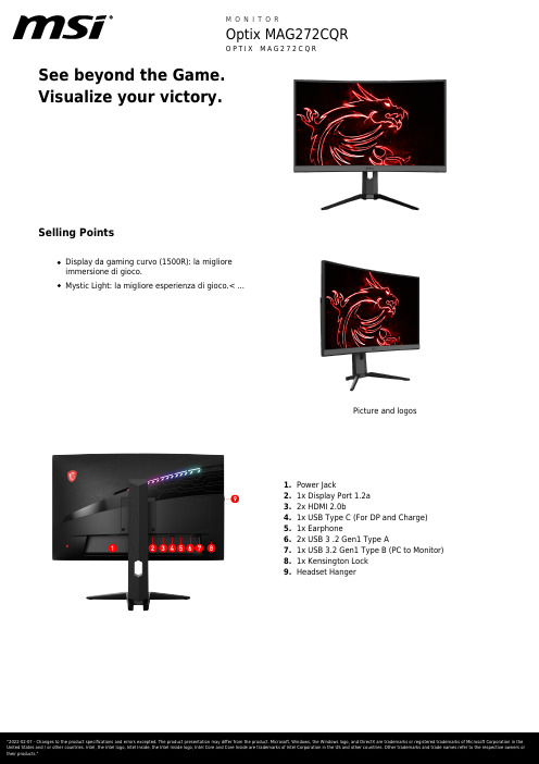
See beyond the Game.Visualize your victory.Selling PointsDisplay da gaming curvo (1500R): la miglioreimmersione di gioco.Mystic Light: la migliore esperienza di gioco.< ...Picture and logos1.Power Jack2.1x Display Port 1.2a3.2x HDMI 2.0b1x USB Type C (For DP and Charge)4.5.1x Earphone6.2x USB 3 .2 Gen1 Type A7.1x USB 3.2 Gen1 Type B (PC to Monitor)8.1x Kensington Lock9.Headset HangerSpecificationScreen Size27" (69 cm)Active Display Area (mm)596.736 (H) x 335.664 (V) Curvature Curve 1500RPanel Type VAResolution2560x1440 (WQHD)Aspect Ratio16:9Dynamic Refresh Rate technology FreeSyncHDR (High dynamic range)HDR readySDR Brightness (nits)250Contrast Ratio3000:1DCR (Dynamic Contrast Ratio)100000000:1Signal Frequency70.56~214.56 KHz(H) / 48~165 Hz(V) Refresh Rate165HZResponse Time (MPRT)1ms(MPRT)Response Time (GTG)4msResponse Time (Tr + Tf)N/AView Angles178°(H)/178°(V)Surface Treatment Anti-glareNTSC (CIE1976 area percentageoverlap)100.6% / 86.0%NTSC (CIE1931 area percentageoverlap)85.1% / 79.5%sRGB (CIE1976 area percentageoverlap)115.4% / 98.7%sRGB (CIE1931 area percentageoverlap)120.1% / 99.7%Adobe RGB (CIE1976 area percentageoverlap)98.9% / 89.9%Adobe RGB (CIE1931 area percentageoverlap)89.0% / 83.2%DCI-P3 (CIE1976 area percentageoverlap)91.9% / 91.8%DCI-P3 (CIE1931 area percentageoverlap)89.0% / 83.2%Rec.709 (CIE1976 area percentageoverlap)115.4% / 98.7%Rec.709 (CIE1931 area percentageoverlap)120.1% / 99.7%Display Colors 1.07BColor bit10 bits (8 bits + FRC)Note_DP2560 x1440 (Up to 165Hz)Note_HDMI2560 x1440 (Up to 165Hz)Note_DVI N/AHDMI2HDMI version 2.0HDMI HDCP version N/ADisplayPort1DisplayPort version 1.2aDisplayPort HDCP version N/AThunderbolt version N/AThunderbolt HDCP version N/AUSB Type C (DisplayPort Alternate)1DVI NAD-Sub NAMic-in NAHeadphone-out1Audio Combo NALock type Kensington LockUSB 2.0 Type B NAUSB 3.2 Gen 1 Type B1Thunderbolt N/AUSB 2.0 Type A NAUSB 2.0 Type C NAUSB 3.2 Gen 1 Type A2USB 3.2 Gen 1 Type C NAUSB 3.2 Gen 2x2 Type C NAUSB 3.2 Gen 2x2 Type A NACard Reader NAPower Type Power CablePower Input100~240V, 50/60HzAdapter's KC safety Number N/APower Cord Type N/AQC Output N/AQC Output Power N/APD Output N/APD Output Power N/AAdjustment (Tilt)-5° ~ 20°Adjustment (Swivel)NAAdjustment (Height)0 ~ 130 mm Adjustment (Pivot)NAVESA Mounting100x100mm Frameless Design YesOuter Carton Dimension (WxDxH) (mm)770 x 183 x 595 Outer Carton Dimension (WxDxH) (inch)30.31 x 7.2 x 23.43 Product Dimension with Stand (WxDxH) (mm)611.5 x 267 x 560 Product Dimension with Stand (WxDxH) (inch)24.07 x 10.51 x 22.05611.5 x 87.5 x 372.74 Product Dimension without Stand (WxDxH)(mm)Product Dimension without Stand (WxDxH)24.07 x 3.44 x 14.67 (inch)Stand Dimension (WxDxH) (mm)453 x 225 x 263.5 Stand Dimension (WxDxH) (inch)17.83 x 8.86 x 10.37 Inside Carton Dimension (WxDxH) (mm)770 x 183 x 595 Inside Carton Dimension (WxDxH) (inch)30.31 x 7.2 x 23.43 Weight (Net kg) 5.9Weight (Gross kg)13.1DisplayPort Cable1HDMI Cable1DVI Cable0USB Type A to Type B Cable1USB Type C to Type A Cable N/AUSB Type C to Type C Cable0Thunderbolt Cable N/AVGA Cable03.5mm audio Cable03.5mm combo audio Cable0Power Cord1AC Adaptor0Warranty Card1Quick Guide1Warranty36MSKU Number0Color ID1/Black-BlackEAN4719072682040。
GMX步骤解释2
科研笔记1:Gromacs安装以前跑MD都是用NAMD软件包,今天开始正式使用Gromacs软件包。
在安装过程中看了网上很多的安装方法,其实大部分都已经过时,这里专述一文,帮助大家入门。
第一步:下载最新版本的Gromacs软件包,比如2014.4.3最新正式版本是gromacs-4.6.5.tar.gz。
注意:由于4.6.x及其以上版本和4.5.x及其以下版本使用的安装方式完全不同,4.6.x使用CMake(Cross Platform Make)编译,方便很多。
参考网站:/Downloads第二步:进行安装按照以下指令:tarxfz gromacs-4.6.5.tar.gzcd gromacs-4.6.5mkdir buildcd buildcmake .. -DGMX _BUILD_OWN_FFTW=ONmakesudo make install参考资料:/Documentation/Installation_Instructions第三步:添加环境变量在我的文件夹里,比如说home/chenqu(举个例子)终端控制台输入:cd ~ls -a (列举当前目录下所有文件)就能看到文件.bashrc了。
vi .bashrc在最后一行添上:export PATH=/usr/local/gromacs/bin:$PATH保存退出wq运行:source .bashrc让PATH路径生效。
科研笔记2:如何添加自己的力场参数1GROMACS实例分析1:CO2+H2O体系大部分GROMACS在线指南都是生物体系,但是对于简单的小体系提到的并不多。
尽管原理一样,我们还是希望能了解如何自己写简单气体的力场。
这里我做一个CO2和H2O混合体系的例子来说明二元混合体系的构建方法,做一个入门指南。
目标:计算CO2在水中的扩散系数。
第一步:使用Avogadro软件构建一个CO2.pdb。
如下所示。
如果不会使用Avogadro软件的,可以研究教程/wiki/Category:Tutorials,这里不再赘述。
1PPC控制器故障代码查询重要

Rexroth IndraControl VCP 20Industrial Hydraulics Electric Drivesand ControlsLinear Motion andAssembly Technologies PneumaticsServiceAutomationMobileHydraulicsRexroth VisualMotion 10 Multi-Axis Machine Control R911306327 Edition 01Troubleshooting GuideAbout this Documentation Rexroth VisualMotion 10 Troubleshooting Guide DOK-VISMOT-VM*-10VRS**-WA01-EN-PRexroth VisualMotion 10Multi-Axis Machine ControlTroubleshooting Guide DOK-VISMOT-VM*-10VRS**-WA01-EN-P Document Number, 120-2300-B323-01/ENPart of Box Set, 20-10V-EN (MN R911306370)This documentation describes …•the use of VisualMotion Toolkit for assitance in diagnostics •the proper steps for indentifing diagnostic faults • and the suggested remedies for clearing faults Description ReleaseDateNotes DOK-VISMOT-VM*-10VRS**-WA01-EN-P 08/2004Initial release© 2004 Bosch Rexroth AGCopying this document, giving it to others and the use or communicationof the contents thereof without express authority, are forbidden. Offendersare liable for the payment of damages. All rights are reserved in the eventof the grant of a patent or the registration of a utility model or design(DIN 34-1).The specified data is for product description purposes only and may notbe deemed to be guaranteed unless expressly confirmed in the contract.All rights are reserved with respect to the content of this documentationand the availability of the product.Bosch Rexroth AGBgm.-Dr.-Nebel-Str. 2 • D-97816 Lohr a. MainTel.: +49 (0)93 52/40-0 • Fax: +49 (0)93 52/40-48 85 • Telex: 68 94 21Bosch Rexroth Corporation • Electric Drives and Controls5150 Prairie Stone Parkway • Hoffman Estates, IL 60192 • USATel.: 847-645-3600 • Fax: 847-645-6201/Dept. ESG4 (DPJ)This document has been printed on chlorine-free bleached paper.Title Type of DocumentationDocument TypecodeInternal File Reference Purpose of Documentation Record of Revisions Copyright Validity Published byNoteRexroth VisualMotion 10 Troubleshooting Guide Table of Contents I Table of Contents1VisualMotion Tools for Diagnosing1-1 The Diagnostics Menu.............................................................................................................1-1System Diagnostics.................................................................................................................1-1Tasks Diagnostics...................................................................................................................1-3Drive Overview….....................................................................................................................1-42Monitoring and Diagnostics2-12.1System Diagnostics - Codes and Message...................................................................................2-1Parameters..............................................................................................................................2-2DriveTop..................................................................................................................................2-32.2Control Startup Messages.............................................................................................................2-4PPC Boot-Up Sequence..........................................................................................................2-4Control Firmware Sequence....................................................................................................2-42.3Status Messages (001-199)...........................................................................................................2-5001 Initializing System.............................................................................................................2-5002 Parameter Mode...............................................................................................................2-5003 Initializing Drives...............................................................................................................2-5004 System is Ready...............................................................................................................2-5005 Manual Mode....................................................................................................................2-5006 Automatic Mode: ABCD....................................................................................................2-5007 Program Running: ABCD.................................................................................................2-6008 Single-Stepping: ABCD....................................................................................................2-6009 Select Parameter Mode to Continue................................................................................2-6010 Breakpoint Reached: ABCD.............................................................................................2-6018 Please cycle power to continue........................................................................................2-6019 Executing User Initialization Task....................................................................................2-62.4Warning Messages (201-399).......................................................................................................2-7201 Invalid jog type or axis selected........................................................................................2-7202 Drive %d is not ready.......................................................................................................2-7203 Power Fail detected..........................................................................................................2-7204 Sercos ring was disconnected..........................................................................................2-8205 Parameter transfer warning in Task %c...........................................................................2-8207 Axis %d position limit reached..........................................................................................2-8208 Lost Fieldbus Connection.................................................................................................2-9209 Fieldbus Mapping Timeout...............................................................................................2-9210 File System Defrag: %d completed................................................................................2-10211 Program- & Data memory cleared..................................................................................2-10212 Option Card PLS Warning, see ext. diag.......................................................................2-10213 Sercos cycle time changed.............................................................................................2-11214 PCI Bus Cyclic Mapping Timeout...................................................................................2-11 DOK-VISMOT-VM*-10VRS**-WA01-EN-PII Table of Contents Rexroth VisualMotion 10 Troubleshooting Guide215 RECO I/O Failure, see ext. diag.....................................................................................2-11216 Control PLS %d warning, see ext. diag..........................................................................2-12217 PCI Bus Communication, see ext. diag..........................................................................2-12218 PCI Bus Register Mapping Timeout...............................................................................2-13219 PCI Bus Lifecounter Timeout.........................................................................................2-13220 Excessive deviation in PMG%d, see ext. diag...............................................................2-13221 Excessive Master Position Slip Deviation......................................................................2-13222 ELS Config. Warning, see ext. diag...............................................................................2-14223 PCI Bus reset occurred, cyclic data are invalid..............................................................2-14225 System booted................................................................................................................2-14226 RS485 Serial Communication Error (port X1%d)...........................................................2-15227 Control Over-temperature Warning................................................................................2-15228 Control - SYSTEM WARNING.......................................................................................2-152.5Shutdown Messages (400 - 599).................................................................................................2-16400 EMERGENCY STOP......................................................................................................2-16401 Sercos Controller Error: %02d........................................................................................2-16402 Sercos Config. Error: see ext. diag................................................................................2-16403 System Error see ext. diag.............................................................................................2-17405 Phase %d: Drive did not respond...................................................................................2-17407 Drive %d Phase 3 Switch Error......................................................................................2-17409 Sercos Disconnect Error.................................................................................................2-18411 Drive %d Phase 4 Switch Error......................................................................................2-18412 No drives were found on ring..........................................................................................2-18414 Parameters were lost......................................................................................................2-19415 Drive %d was not found..................................................................................................2-19416 Invalid Instruction at %04x..............................................................................................2-19417 SYSTEM ERROR: pSOS #%04x...................................................................................2-19418 No program is active.......................................................................................................2-20419 Invalid Program File: code = %d....................................................................................2-20420 Drive %d Shutdown Error...............................................................................................2-20421 User Program Stack Overflow........................................................................................2-20422 Parameter transfer error in Task %c..............................................................................2-21423 Unimplemented Instruction.............................................................................................2-21425 Instruction error: see Task %c diag................................................................................2-21426 Drive %d is not ready.....................................................................................................2-22427 Calc: invalid table index %d............................................................................................2-22428 Calc: division by zero......................................................................................................2-22429 Calc: too many operands................................................................................................2-22430 Calc: invalid operator......................................................................................................2-23431 Calc error: see Task %c diag.........................................................................................2-23432 Calc: too many nested expressions...............................................................................2-23433 Setup instruction outside of a task.................................................................................2-23434 Axis %d configured more than once...............................................................................2-23435 Axis %d is not assigned to a task...................................................................................2-24436 General Compiler Error: %04x.......................................................................................2-24438 Invalid Axis Selected: %d...............................................................................................2-24DOK-VISMOT-VM*-10VRS**-WA01-EN-PRexroth VisualMotion 10 Troubleshooting Guide Table of Contents III439 Axis %d: Invalid Motion Type.........................................................................................2-24440 I/O Transfer Error: see task diag....................................................................................2-25450 Event %d: invalid event type..........................................................................................2-25451 Invalid event number ‘%d’..............................................................................................2-25452 More than %d event timers armed.................................................................................2-25453 Homing param. transfer error: %d..................................................................................2-25454 Axis %d homing not complete........................................................................................2-26459 Axis %d target position out of bounds............................................................................2-26460 Invalid program %d from binary inputs...........................................................................2-26463 Ratio command: invalid ratio..........................................................................................2-26464 Can't activate while program running.............................................................................2-27465 Drive %d config. error, see ext. diag..............................................................................2-27467 Invalid ELS Master Option..............................................................................................2-27468 ELS adjustment out of bounds.......................................................................................2-27470 Axis %d velocity > maximum..........................................................................................2-28474 Drive %d cyclic data size too large.................................................................................2-28477 Axis D: probe edge not configured.................................................................................2-28478 Calc: operand out of range.............................................................................................2-28483 Parameter Init. Error: see Task %c diag........................................................................2-29484 Control SYSTEM ERROR..............................................................................................2-29486 Sercos Device %d is not a drive.....................................................................................2-29487 CAM %d is invalid or not stored.....................................................................................2-29488 CAM Error: See Task %c diag........................................................................................2-30489 More than %d CAM axes selected.................................................................................2-30490 System Memory Allocation Error....................................................................................2-30492 Programs were lost, see ext. diag..................................................................................2-30496 Can't execute this instruction from an event..................................................................2-31497 Limit switch config. error, see ext. diag.........................................................................2-31498 Drive %d Shutdown Warning..........................................................................................2-32499 Axis number %d not supported in this version...............................................................2-32500 Axis %d is not referenced...............................................................................................2-32501 Drive %d comm. error, see ext. diag..............................................................................2-33502 ELS and cams not supported in this version..................................................................2-33504 Communication Timeout.................................................................................................2-33505 Axis %d is not configured...............................................................................................2-33508 User Watchdog Timeout.................................................................................................2-33509 Control System Timing Error (%d).................................................................................2-34515 PLC Communications Error............................................................................................2-34516 More than %d registration functions enabled.................................................................2-34519 Lost Fieldbus/PLC Connection.......................................................................................2-35520 Fieldbus Mapping Timeout.............................................................................................2-35521 Invalid Virtual Master ID: %d..........................................................................................2-36522 Invalid ELS Master ID: %d..............................................................................................2-36523 IFS status, facility = 0x%x..............................................................................................2-36524 Hardware Watchdog timeout..........................................................................................2-36525 I/O Configuration error, see ext. diag.............................................................................2-36 DOK-VISMOT-VM*-10VRS**-WA01-EN-PIV Table of Contents Rexroth VisualMotion 10 Troubleshooting Guide526 Sercos Multiplex Channel Config, see ext. diag.............................................................2-37527 Control Initialization Error, see ext. diag.........................................................................2-38528 System Event %d Occurred...........................................................................................2-38529 Invalid ELS Group ID: %d...............................................................................................2-38530 CAM %d is active, can't overwrite..................................................................................2-39531 Invalid variable for Fieldbus/PCI Bus Mapping...............................................................2-39532 Power fail brown out condition detected.........................................................................2-39533 Multiple instances of index CAM: %d found...................................................................2-39534 Hardware Version Not Supported..................................................................................2-40539 Invalid Parameter Number..............................................................................................2-40540 Option Card PLS error....................................................................................................2-40541 Link Ring Error, see ext. diag.........................................................................................2-41542 PLC Cyclic Mapping Timeout.........................................................................................2-42543 PCI Bus Runtime Error...................................................................................................2-42544 RECO I/O Failure, see ext. diag.....................................................................................2-42545 Invalid Coordinated Articulation Function ID: %d...........................................................2-43546 Multiple Instance of Coordinated Articulation Function with ID: %d...............................2-43547 Task %c Coordinated Articulation Error, see ext. diag...................................................2-43548 Invalid Kinematic Number: %d.......................................................................................2-43549 Fieldbus Initialization Error.............................................................................................2-43550 User Initialization Task Timeout.....................................................................................2-44551 Master Slip Config. Error, see ext. diag..........................................................................2-44552 Excessive Master Position Slip Deviation......................................................................2-44553 Invalid Parameter Detected, see C-0-2002....................................................................2-44554 Excessive Deviation in PMG%d, see ext. diag...............................................................2-45555 PCI Bus Register Mapping Timeout...............................................................................2-45556 PCI Bus Lifecounter Timeout.........................................................................................2-45557 PMG%d Maximum allowed deviation window is Zero....................................................2-45558 PMG%d Only 1 axis parameterized...............................................................................2-46559 PMG%d Number of offsets does not match number of Axis..........................................2-46560 PMG%d Max. allowed dev. window is larger than 25% of Modulo................................2-46561 PMG%d Offset is larger than Modulo.............................................................................2-46562 PMG%d Parameterized Axis is not in system................................................................2-46563 Invalid Task Specified, Must be A-D..............................................................................2-46564 PMG%d Invalid configuration, see ext. diag...................................................................2-46565 Axis %d: Configuration error, see ext. diag....................................................................2-47566 Filter sample rate and cutoff frequency mismatch.........................................................2-47567 ELS Config. Error, see ext. diag.....................................................................................2-47568 Axis %d: Assigned Task is Not Defined.........................................................................2-48570 ELS Max. Vel. Exceeded, see ext. diag.........................................................................2-48571 No Program Found.........................................................................................................2-49572 PCI Bus reset occurred, cyclic data is invalid.................................................................2-49573 CAM %d is being built....................................................................................................2-49575 ELS Master for ELS Group %d is invalid........................................................................2-49576 Event for input I%d is already armed, cannot arm again...............................................2-50577 Restored non volatile memory from compact flash........................................................2-50DOK-VISMOT-VM*-10VRS**-WA01-EN-PRexroth VisualMotion 10 Troubleshooting Guide Table of Contents V578 Virtual Master %d Exceeded Its Max. Vel., see ext. diag...............................................2-50579 Group %d Exceeded Its Jog Velocity, see ext. diag......................................................2-51580 pROBE Error Occurred in Task:0x%04X.......................................................................2-51581 Probe Function for Axis # is locked by the PLC.............................................................2-51582 Integrated PLC: PLC Stopped in Operation Mode.........................................................2-51583 Integrated PLC: Internal System Error...........................................................................2-51584 ELS System Master %d is invalid, see ext. diag............................................................2-51585 Drive %d separate deceleration not supported..............................................................2-52586 Master Encoder Card Error, see ext diag.......................................................................2-522.6Integrated PLC Status Messages................................................................................................2-536001 Integrated PLC: Running..............................................................................................2-536002 Integrated PLC: Stopped..............................................................................................2-536002 Integrated PLC: Stopped at Breakpoint........................................................................2-532.7Integrated PLC Error Codes........................................................................................................2-530016 Integrated PLC: Software Watchdog Error...................................................................2-530019 Integrated PLC: Program Checksum Error..................................................................2-530020 Integrated PLC: Fieldbus Master Error.........................................................................2-540021 Integrated PLC: I/O Update Error.................................................................................2-542000 Integrated PLC: Internal SIS System Error..................................................................2-542001 Integrated PLC: Internal Acyclic Access Error.............................................................2-542002 Integrated PLC: Internal Acyclic Memory Error............................................................2-542003 Integrated PLC: PLC Configuration Error.....................................................................2-552004 Integrated PLC: File Access Error................................................................................2-552005 Integrated PLC: Internal Fatal Task Error....................................................................2-556011 Integrated PLC: PLC Program Stopped in Operation Mode........................................2-556012 Integrated PLC: General Error.....................................................................................2-552.8Communication Error Codes and Messages...............................................................................2-56!01 Sercos Error Code # xxxx...............................................................................................2-56!02 Invalid Parameter Number..............................................................................................2-57!03 Data is Read Only...........................................................................................................2-57!04 Write Protected in this mode/phase...............................................................................2-57!05 Greater than maximum value.........................................................................................2-57!06 Less than minimum value...............................................................................................2-57!07 Data is Invalid.................................................................................................................2-57!08 Drive was not found........................................................................................................2-57!09 Drive not ready for communication.................................................................................2-57!10 Drive is not responding...................................................................................................2-57!11 Service channel is not open...........................................................................................2-57!12 Invalid Command Class..................................................................................................2-57!13 Checksum Error: xx (xx= checksum that control calculated).........................................2-58!14 Invalid Command Subclass............................................................................................2-58!15 Invalid Parameter Set.....................................................................................................2-58!16 List already in progress..................................................................................................2-58!17 Invalid Sequence Number..............................................................................................2-58!18 List has not started.........................................................................................................2-58!19 List is finished.................................................................................................................2-58 DOK-VISMOT-VM*-10VRS**-WA01-EN-P。
操作指南
matlab中axis用法 -回复
matlab中axis用法-回复关于MATLAB中axis函数的使用,我将逐步回答你关于该函数的问题,并详细介绍其使用方法和功能。
我将以一个1500-2000字的文章来解释,以确保你对axis函数有一个全面的理解。
第一部分:什么是axis函数?在MATLAB中,axis函数是一个用于设置或获取坐标轴属性的函数。
坐标轴是一个绘图区域内的直角坐标系,用于确定绘图中数据点的位置和比例。
axis函数可以用来设置坐标轴的显示范围、刻度线位置和标签等属性,以及获取当前的坐标轴属性值。
第二部分:axis函数的基本用法在MATLAB中,axis函数有两种基本的用法:设置坐标轴属性和获取坐标轴属性。
设置坐标轴属性:axis('属性名称', 值)用于设置指定属性的值。
例如,如果你想设置x轴的显示范围为0到10,你可以使用axis('xlim', [0 10])。
获取坐标轴属性:value = axis('属性名称')用于获取指定属性的值。
例如,如果你想获取y 轴的显示范围,你可以使用value = axis('ylim')。
第三部分:示例为了更好地理解axis函数的使用,让我们来看几个示例。
示例1:设置坐标轴的显示范围在MATLAB中,你可以使用axis函数来设置坐标轴的显示范围。
假设你有一组数据点,x的范围为0到100,y的范围为-10到10。
你可以使用axis函数来设置x轴和y轴的显示范围。
例如:x = 0:1:100;y = sin(x);plot(x, y);axis([0 100 -10 10]);这将使x轴的范围在0到100之间,并将y轴的范围限制在-10到10之间。
示例2:设置坐标轴刻度线的位置和标签在绘图中,你可能希望设置坐标轴上刻度线的位置和标签。
axis函数可以帮助你实现这一目标。
考虑以下示例:x = 0:0.1:2*pi;y = sin(x);plot(x, y);axis([0 2*pi -1 1]);xticks(0:pi/2:2*pi);yticks(-1:0.5:1);这将在x轴上设置刻度线的位置为0、π/2、π、3π/2和2π,并在y轴上设置刻度线的位置为-1、-0.5、0、0.5和1。
Matrox Meteor-II Camera Link Camera接口应用说明书
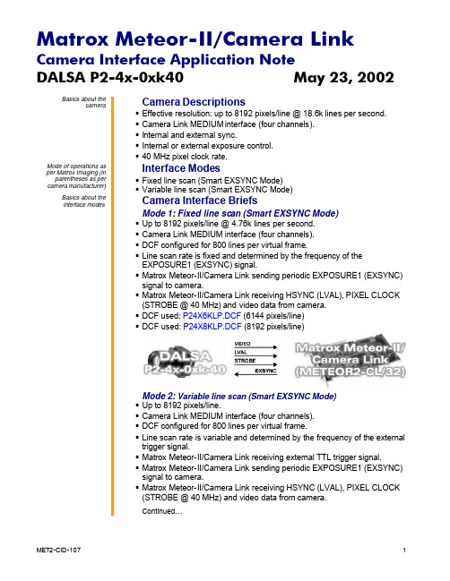
DALSA P2-4x-0xk40 May 23, 2002 Basics about thecameraCamera Descriptions§§ Camera Link MEDIUM interface (four channels).§ Internal and external sync.§ Internal or external exposure control.§ 40 MHz pixel clock rate.Mode of operations as per Matrox Imaging (in parentheses as per camera manufacturer)Interface Modes§ Fixed line scan (Smart EXSYNC Mode)§ Variable line scan (Smart EXSYNC Mode)Basics about theinterface modesCamera Interface BriefsMode 1: Fixed line scan (Smart EXSYNC Mode)§§ Camera Link MEDIUM interface (four channels).§ DCF configured for 800 lines per virtual frame.§ Line scan rate is fixed and determined by the frequency of theEXPOSURE1 (EXSYNC) signal.§ Matrox Meteor-II/Camera Link sending periodic EXPOSURE1 (EXSYNC)signal to camera.§ Matrox Meteor-II/Camera Link receiving HSYNC (LVAL), PIXEL CLOCK(STROBE @ 40 MHz) and video data from camera.§ DCF used: P24X6KLP.DCF (6144 pixels/line)§ DCF used: P24X8KLP.DCF(8192 pixels/line)Mode 2: Variable line scan (Smart EXSYNC Mode)§ Up to 8192 pixels/line.§ Camera Link MEDIUM interface (four channels).§ DCF configured for 800 lines per virtual frame.§ Line scan rate is variable and determined by the frequency of the externaltrigger signal.§ Matrox Meteor-II/Camera Link receiving external TTL trigger signal.§ Matrox Meteor-II/Camera Link sending periodic EXPOSURE1 (EXSYNC)signal to camera.§ Matrox Meteor-II/Camera Link receiving HSYNC (LVAL), PIXEL CLOCK(STROBE @ 40 MHz) and video data from camera.Continued…DALSA P2-4x-0xk40 May 23, 2002 Basics about theCamera Interface Briefs (cont.)interface modesMode 2: Variable line scan (Smart EXSYNC Mode)§ DCF used: P24X6KLV.DCF (6144 pixels/line)§ DCF used: P24X8KLV.DCF (8192 pixels/line)Specifics about theCamera Interface Detailsinterface modesMode 1: Fixed line scan (Smart EXSYNC Mode)§Line rate: The frequency of the periodic EXPOSURE1 (EXSYNC) signalcontrols the camera’s line rate. The EXPOSURE1 (EXSYNC) signalperiod for this mode is set to 210 µs which translates into a 4.76 kHz linerate. The maximum line rate equals 18.6/24.4 kHz respectively for the8k/6k models. NOTE: Capture to the Matrox Meteor-II/Camera Link on-board memory is necessary when grabbing at rates above approximately80 MB/sec. (system dependent). Moreover, when grabbing to on-boardmemory, a limit of roughly 5400/4000 lines (6K/8K model respectively)can be acquired before the on-board memory fills up and the grab willneed to be halted to allow a data transfer to the host in order to free upthe on-board memory. At a lower rate (e.g. long exposure or a slowerexternal trigger frequency), it will be possible to grab directly andcontinuously into system memory.§Exposure time: Exposure time is the active (high level) period betweenthe rising and falling edges of the EXPOSURE1 (EXSYNC) signal. Thedefault exposure time for this mode is 100 µs. The exposure time can bemodified in the DCF using Matrox Intellicam or with the MIL MdigControl()function. Refer to the respective manual for more information.§Maximum/Minimum: Since the Matrox Meteor-II/Camera Link timer is16-bit wide, the maximum exposure time for this dcf is calculated to be65536/20MHz = 3.28 ms. When the exposure time equals 100 µs, themaximum line rate can be calculated to be exposure time + line read out+ internal delay or 100 µs + 38.4µs + 1.52 µs = 139.92 µs or 7.15kHz forthe 6k model (6.50 kHz for the 8k model). The pixel clock is the referenceclock in which the exposure time is being set by, therefore the smallesttime increment equals 50 ns.DALSA P2-4x-0xk40 May 23, 2002 Specifics about theCamera Interface Details (cont.)interface modesMode 1: Fixed line scan (Smart EXSYNC Mode)§Inverted tap output: The tap output configuration features mirrored tapswhich will need to be inverted. Additional processing time will be requiredin order to invert the 3rd and 4th taps. For a sample program or additionalinformation, contact Matrox Imaging Technical Support.§Camera Communications: Refer to the camera manual for additionalinformation. The following camera configuration is set via the CameraLink Serial communication:Command Short Form Parameter Descriptionset_exposure_mode sem 4 SMART EXSYNC modeMode 2: Variable line scan (Smart EXSYNC Mode)§Line rate: The line rate is variable and determined by the frequency ofthe external trigger signal. The external TTL trigger signal period must belarger than the total duration of the exposure time (high level duration ofthe timer), the internal delay of the camera (1.52 µs) and the line rate(38.4 µs for the 6k model or 51.2 µs for the 8k model). NOTE: Capture tothe Matrox Meteor-II/Camera Link on-board memory is necessary whengrabbing at rates above approximately 80 MB/sec. (system dependent).Moreover, when grabbing to on-board memory, a limit of roughly5400/4000 lines (6K/8K model respectively) can be acquired before theon-board memory fills up and the grab will need to be halted to allow adata transfer to the host in order to free up the on-board memory. At alower rate (e.g. long exposure or a slower external trigger frequency), itwill be possible to grab directly and continuously into system memory.§Exposure time: Same as in Mode 1: Fixed line scan.§Maximum/Minimum: Same as in Mode 1: Fixed line scan.§Inverted tap output: Same as in Mode 1: Fixed line scan.§Camera Communications: Same as in Mode 1: Fixed line scan.§Timing diagram:DALSA P2-4x-0xk40 May 23, 2002 Cabling details for theCabling Requirementsinterface modesMode 1: Fixed line scan (Smart EXSYNC Mode)Cable and Connection: Standard Camera Link cable.Mode 2: Variable line scan (Smart EXSYNC Mode)Cable and Connection: Standard Camera Link.External trigger: External trigger should be connected to the OPTOTRIG input of the DB9 connector (pins 2 and 7) on the Expanded I/Oadapter bracket.EXPANDED I/O BRACKET(DB9 connector) External Trigger SourceOPTOTRIG + 07 ←SIGNAL --OPTOTRIG - 02 ←GROUND --The DCF(s) mentioned in this application note can be found on our FTP site (/pub/imaging/).The information furnished by Matrox Electronics System, Ltd. is believed to be accurate and reliable. Please verify all interface connections with camera documentation or manual. Contact your local sales representative or Matrox Sales office or Matrox Imaging Applications at 514-822-6061 for assistance.Matrox Electronic Systems Ltd.1055 St. Regis Blvd.Dorval, Quebec H9P 2T4CanadaTel: (514) 685-2630Fax: (514) 822-6273。
Matrox Meteor-II Camera Link摄像头接口应用指南说明书
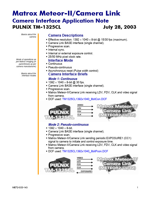
PULNiX TM-1325CL July 28, 2003Basics about thecameraCamera Descriptions § Effective resolution: 1392 × 1040 × 8-bit @ 15/30 fps (maximum). § Camera Link BASE interface (single channel). § Progressive scan. § Internal sync. § Internal or external exposure control. § 25/50 MHz pixel clock rate. Mode of operations asper Matrox Imaging (inparentheses as percamera manufacturer)Interface Mode § Continuous § Pseudo-continuous § Asynchronous reset (Pulse width control) Basics about theinterface modesCamera Interface Briefs Mode 1: Continuous § 1392 × 1040 × 8-bit @ 30 fps. § Camera Link BASE interface (single channel). § Progressive scan. § Matrox Meteor-II/Camera Link receiving LDV, FDV, CLK and video signal from camera. § DCF used:TM1325CL1392x1040_8bitCon.DCFMode 2: Pseudo-continuous § 1392 × 1040 × 8-bit. § Camera Link BASE interface (single channel). § Progressive scan. § Matrox Meteor-II/Camera Link sending periodic EXPOSURE1 (CC1) signal to camera to initiate and control exposure time. § Matrox Meteor-II/Camera Link receiving LDV, FDV, CLK and video signal from camera. § DCF used: TM1325CL1392x1040_8bitPcon.DCFPULNiX TM-1325CL July 28, 2003 Basics about theCamera Interface Briefs (cont.)interface modesMode 3: Asynchronous reset§ 1392 × 1040 × 8-bit.§ Camera Link BASE interface (single channel).§ Progressive scan.§ Matrox Meteor-II/Camera Link receiving external trigger signal.§ Matrox Meteor-II/Camera Link sending EXPOSURE1 (CC1) signal tocamera to initiate and control exposure time.§ Matrox Meteor-II/Camera Link receiving LDV, FDV, CLK and video signalfrom camera.§ DCF used: TM1325CL1392x1040_8bitAsync.DCFSpecifics about theCamera Interface Detailsinterface modesMode 1: Continuous§Frame Rate: Matrox Meteor-II/Camera Link receives the continuousvideo from the camera at 30 frames per second at full resolution.§Exposure time: Exposure time is determined by the shutter setting.Refer to the camera manual for more information.§Camera Control Software settings: Shutter mode and Scan mode setto No Shutter and 30 FPS respectively. Camera Control Software version3.2 or higher can be used.Mode 2: Pseudo-continuous§Frame Rate: For this DCF, the Matrox Meteor-II/Camera Link receivesthe pseudo-continuous video from the camera at about 22 frames persecond (22.35 Hz) for full resolution.§Exposure time: Exposure time is determined by the inactive period ofTimer1 setting in the DCF. It is recommended that the active period ofTimer1 be set to greater than one frame duration.The default exposuretime in this DCF is 5.6 ms, which can be modified using MatroxIntellicam, with the ONL imCamControl() or imDigControl() function, orwith the MIL MdigControl() function. Refer to the respective manual formore information.§Camera Control Software settings: Shutter mode and Scan mode setto Async and 30 FPS respectively. Shutter switch set to 9 or EXT.PWCONTROL. Camera Control Software version 3.2 or higher can be used.PULNiX TM-1325CL July 28, 2003 Specifics about theCamera Interface Details (cont.)interface modesMode 2: Pseudo-continuous§Timings diagram:Mode 3: Asynchronous reset§Frame Rate: The frame rate is determined by the frequency of theexternal trigger signal. The period between external TTL trigger signalsmust be larger than the total duration of the exposure time (inactiveperiod of Timer1) plus the time for one frame.§Exposure time: The width (falling edge to rising edge) of theEXPOSURE1 (CC1) signal is the exposure time. The default exposuretime in this DCF is 5.6 ms, which can be modified using MatroxIntellicam, ONL imCamControl() or imDigControl() function, or with theMIL MdigControl() function. Refer to the respective manual for moreinformation.Note that due to the negative polarity of the exposure signal, thefirst capture (grab) in this mode will be improperly exposed andshould be discarded.§Camera Control Software settings: Shutter mode and Scan mode setto Async and 30 FPS respectively. Shutter switch set to 9 or EXT.PWCONTROL. Camera Control Software version 3.2 or higher can be used.§Timings diagram:Cabling details for theCabling Requirementsinterface modesModes 1 and 2: Continuous and Pseudo-continuous§Cable and Connection: Standard Camera Link cable.PULNiX TM-1325CL July 28, 2003 Cabling details for theCabling Requirements (cont.)interface modesMode 3: Asynchronous resetCable and Connection: Standard Camera Link.External trigger: External trigger should be connected to the OPTOTRIG input of the 9-pin connector (pins 7 and 2) on the Expanded I/Oadapter bracket.EXPANDED I/O BRACKET(9-pin connector) External Trigger SourceOPTOTRIG + 07 ←SIGNAL --OPTOTRIG - 02 ←GROUND --The DCF(s) mentioned in this application note can be found on our FTP site (/pub/imaging/).The information furnished by Matrox Electronics System, Ltd. is believed to be accurate and reliable. Please verify all interface connections with camera documentation or manual. Contact your local sales representative or Matrox Sales office or Matrox Imaging Applications at 514-822-6061 for assistance.Matrox Electronic Systems Ltd.1055 St. Regis Blvd.Dorval, Quebec H9P 2T4CanadaTel: (514) 685-2630Fax: (514) 822-6273。
FeiYu WG2 3 Axis Wearable Gimbal 使用说明书

FY WG2 3 Axis Wearable Gimbal and cameras with similar dimensions GuiLin FeiYu Technology Incorporated CompanyInstruct io n ManualENV 1.0Usage Scenario DemonstrationWG2 has precision machinery transmission mechanism, water proof design can completely use in raining and water splash scene, it can be used in the water under certain conditions, please follow the requirements below when use in the water, otherwise, there are risks of damage.1.Please ensure the usb plug has been covered beforeusing underwater, dry it and place in a ventilated placeto dry before charging.3. Used in sea water environment at risk of damagethat is not recommended.2. When use under water, depth of water should be lessthan 0.5m, and time of continuous use less than 5mins.4.When it is splashed by sea water, please wash it withfresh water immediately, and soak it in fresh water for3mins, otherwise, the rotation of gimbal will be blockedby the salt crystals after the sea water dried.※It is normal phenomenon if there is a small amount of liquidflow from gimbal or the gimbal is smelly, the liquid is waterproofpaint, a few pungent smells.3Drift Swimming21User Guide1Install the Camera Remove fixed block,install the camera on retainer plate, 2Power on / offPress and hold function buttonPress and hold function button Attention: Make sure the camera is secure before powering on the gimbal.2Knob ring3Rolling axis1/4 inch screw holeProduct Overview* The showing sports camera is only for referencescrew holeWaterproof4Camera in rightForwardCamera in rightInvertedCamera in rightVerticalApp download and connect12Start the App on your smartphone,follow the instructions to connect the smartphone with gimbal via bluetooth.Download AppDownload "Feiyu ON" and install it.(2) Android version:Google play5*Please scan the two-dimensional code via the browser.6Mode /FunctionThe orientation of the camera is fixed.Panning Mode Tilting and rolling direction are fixed, and the cameralens moves according to the hand movement of the user.Panning and Tilting Mode The rolling direction is fixed, and the camera lens moves according to the hand movement of the user.Lock ModeResetReset the tilting axis of the gimbal to initial orientation and initialmode.Mode /Function Operation InstructionsIndicator StatusMode / StatusBlue light flashes once Blue light flashes twice PanningPanning and tilting mode Lock mode / Initializing Blue light on steadily Blue light keeps flashing Initialization failure /Malfunction Low battery Red light flashes three timesRed light keeps flashingTurning offFunction Button Double tap Single tapMode /FunctionExplanationPanning Mode / Lock Mode Panning and tilting mode Triple tap Single tap to switch between panning mode and lock modeWhen in panning and tilting mode, press once to switch to lock mode Rotate 180°in horizontal Make the camera lens rotate 180 °Quadruple tapQuadruple tap to enter autototation modeAutorotation ModeFifth tapSingle tap again to awake the gimbal, or triple tap to initialize the gimbalInitialization7Autorotation Mode2. Turn the panning axis and tilting axis to the position ① and hold for half a second.Click on function button,record the position ①.4.Gimbal will recover to position ① automatically. Tilting axis and panning axis turn to position ②at constant speed.The gimbal is automatically reset after the end.Four times clicks on function button, gimbal will access the autorotation mode setting. Manually turn the gimbal to an initial position, then click again on function button for recording it.Manually turn the gimbal to end position, then click the functionbutton again for recording it. Gimbal will turn to the initial position and begin autorotation.8Manual LockManual lock ,pull to the specified angle to stay half a second can be lock the current angle.(The tilting axis and panning axis in the lock mode can bemanual lock and the tilting axis can be manual lock in the panning mode.)Take the tilting axis as an example:21direction.Keep this position for half second, the current angle will be locked manually.Annexed parameter table:Gimbal speed setting and theory time adaptation reference table.Combined use of gimbal autorotation function and motion camera time-lapse photography function will make the camera achieve the excellent effect oftime-lapse photography.Theoretical time and gimbal autorotation speed adaptation effect is better, Feiyu ON APP can set the autorotation speed.WG2 theory time1234 (default)569871112108 hours / turn 4 hours / turn 2 hours / turn1 hours / turn (default)30 minutes / turn 15 minutes / turn2 minutes / turn 4 minutes / turn 8 minutes / turn 30 seconds / turn 15 seconds / turn1 minutes / turn WG2 speed setting9Please visit the official website to download the relevant software for upgrading, including USB driver,firmware upgrade software and product firmware, and install the relevant software, decompress the firmware files .Feiyu ONOption 1: connect the gimbal with PC via micro USB cable, and then upgrade the firmware.Option 2: connect the gimbal with smartphone via bluetooth, and then upgrade the firmware.(1)(2)*Please make sure the battery is fullycharged before youuse the gimbal for the first time.Firmware UpgradeFirmware UpgradeChargingThe current used version 1.7.2,new firmware is available,do you want to upgrade?LaterDownload and install it.Adjusting steps:Still placed on the desktop, gimbal is automatically initialized.the function button to turn off the gimbal,restart it and then initialize.210Gimbal initializationYou can initialize your gimbal:(1) when camera is not level (2) if not used for a long period of time(3) in case of extreme temperature variationsParameters1112.5mm89.3mm40mm61.1~78.1mmWeight265 g(Not including camera) Adaption Weight130 gUsage time 2.5 HoursPanning Increments min 1.5°/s max 270°/s Titling Increments min 1.5°/s max 150°/s Panning AngleTitling AngleRolling Angle70°360°360°12D I S C L A I ME R Attention Please correctly assemble the gimbal in accordance with the diagram Please install the camera before powering on the gimbal When the gimbal is not in use or placed on the table, please ensure it is powered offProhibit any user for any illegal purpose. Users will be responsible for all behaviors of purchase and use products.The Company assumes no liability for any risks related to or resulting from the debug and use of this product (including the direct, indirect or third-party losses).For any unknown sources of using, we will not be at any services.The updating and changes of product firmware and program may cause changes in function descriptions in this user manual, please read the instructions carefully before upgrading the firmware and use the corresponding user manual.You can get the latest user manual from the official website: FeiyuTech reserves the right to amend this manual and the terms and conditions of use the product at any time.。
python 卫星钟差预测 二阶多项式拟合
文章标题:Python应用在卫星钟差预测中的二阶多项式拟合一、介绍在卫星导航系统中,卫星钟差的准确预测是非常重要的,它直接影响到导航系统的精度和可靠性。
而预测卫星钟差的一种有效方法是利用二阶多项式拟合。
本文将介绍如何利用Python进行卫星钟差的二阶多项式拟合,并分析其中的原理和优势。
二、Python在卫星钟差预测中的应用1. 数据收集我们需要收集卫星钟差的历史数据。
这些数据可以从卫星导航系统的监测中心获取,也可以通过卫星接收设备进行实时采集。
数据包括卫星编号、时间戳和钟差数值。
2. 数据处理利用Python的数据处理库(如Pandas)可以对数据进行清洗和筛选,去除异常值和缺失数据,以确保数据的准确性和完整性。
还可以利用Matplotlib库进行数据可视化分析,查看历史数据的变化趋势。
3. 二阶多项式拟合Python的Scikit-learn库提供了丰富的机器学习算法和工具,其中包括多项式拟合模型。
通过调用相关函数,可以对卫星钟差数据进行二阶多项式拟合,得到拟合后的模型参数和拟合曲线。
4. 模型评估利用拟合后的模型对历史数据进行预测,并与实际数据进行对比,以评估拟合模型的准确性和预测能力。
可以利用Python的统计分析库进行误差分析和回归分析,进一步优化拟合模型。
三、二阶多项式拟合的优势1. 灵活性二阶多项式拟合相比一阶拟合更加灵活,可以更好地拟合数据的曲线特征,适用于钟差随时间变化的非线性问题。
2. 预测精度通过二阶多项式拟合,可以更准确地预测未来的卫星钟差,提高导航系统的精度和稳定性。
3. 模型简单二阶多项式拟合虽然具有较高的拟合精度,但模型相对简单,计算复杂度较低,适合在实时环境中应用。
四、个人观点和总结通过Python在卫星钟差预测中应用二阶多项式拟合,可以更精准地预测卫星钟差,提高导航系统的性能和可靠性。
Python作为一种强大的编程语言,提供了丰富的数据处理和机器学习工具,为卫星导航系统的优化提供了便利和可能。
gamp中将卫星坐标由xyz转径向切向法向的代码
gamp中将卫星坐标由xyz转径向切向法向的代码【最新版】目录1.GAMP 简介2.坐标转换的背景和意义3.径向切向法向的计算方法4.代码实现5.总结正文1.GAMP 简介GAMP(Geospatial Analysis and Modeling Platform)是一款开源的地理空间分析和建模平台。
它为遥感数据处理、地形分析、地图制图等提供了丰富的工具和函数。
在 GAMP 中,用户可以方便地处理卫星坐标数据。
2.坐标转换的背景和意义在卫星遥感数据处理中,坐标系转换是很常见的操作。
将卫星坐标从常用的笛卡尔坐标系(X,Y,Z)转换为径向切向法向坐标系,有助于更好地描述卫星传感器与地球表面之间的相对关系。
这种坐标系可以简化计算过程,提高数据处理效率,并有利于后续的空间分析和建模工作。
3.径向切向法向的计算方法径向切向法向坐标系(R,T,N)是一个右手坐标系。
其中,R 方向指向地球中心,T 方向与地球表面切线方向相同,N 方向垂直于地球表面。
根据定义,可以计算出各个方向的坐标:- R:R = sqrt(X^2 + Y^2)- T:T = (Y, -X)- N:N = (Z, -R)4.代码实现在 GAMP 中,可以使用以下 Python 代码实现卫星坐标从笛卡尔坐标系到径向切向法向坐标系的转换:```pythonimport numpy as npdef xyz_to_rts(xyz):x = xyz[0]y = xyz[1]z = xyz[2]r = np.sqrt(x**2 + y**2)t = (y, -x)n = (z, -r)return r, t, n# 示例:输入笛卡尔坐标系下的卫星坐标 (1, 2, 3)xyz = np.array([1, 2, 3])# 转换为径向切向法向坐标系r, t, n = xyz_to_rts(xyz)print("R:", r)print("T:", t)print("N:", n)```5.总结通过 GAMP 平台,我们可以方便地将卫星坐标从笛卡尔坐标系转换为径向切向法向坐标系。
Xpose.nlmixr2扩展包:Pharmacometric模型图形诊断工具说明书

Package‘xpose.nlmixr2’October14,2022Type PackageTitle Graphical Diagnostics for Pharmacometric Models:Extension to 'nlmixr2'Version0.4.0Maintainer Justin Wilkins<*************************>Description Extension to'xpose'to support'nlmixr2'.Provides functions to im-port'nlmixr2'fit data into an'xpose'data object,allow-ing the use of'xpose'for'nlmixr2'model diagnostics.License GPL(>=2)Encoding UTF-8Depends R(>=3.2),xpose(>=0.4.2)Imports ggplot2(>=2.2.1),dplyr(>=0.7.4),tibble(>=2.0.0),stringr(>=1.2.0),tidyr(>=0.7.2),magrittr(>=1.5),methods(>=3.4.1),vpc(>=1.0.2),crayon,rlang,nlmixr2estSuggests readr,nlmixr2RoxygenNote7.1.2NeedsCompilation noAuthor Justin Wilkins[aut,cre,cph],Matthew Fidler[aut,cph],Benjamin Guiastrennec[aut],Andrew C.Hooker[aut],Anna Olofsson[aut,cph],Sebastian Ueckert[aut],Ron Keizer[aut],Kajsa Harling[ctb],Mike K.Smith[ctb],Elodie Plan[ctb],Mats O.Karlsson[aut,cph],Pharmetheus[ctb],Pfizer[ctb],Occams[ctb],Novartis[ctb]12summarise_nlmixr2_modelRepository CRANDate/Publication2022-06-0809:10:02UTCR topics documented:nlmixr2_vpc_theme (2)summarise_nlmixr2_model (2)theme_xp_nlmixr2 (3)xpose_data_nlmixr2 (3)Index6 nlmixr2_vpc_theme Default VPC theme for’xpose.nlmixr2’DescriptionDefault VPC theme for’xpose.nlmixr2’.Usagenlmixr2_vpc_themeFormatAn object of class vpc_theme of length23.ValueA list with’vpc’theme specifiers.summarise_nlmixr2_modelData summary functionDescriptionConvert’nlmixr2’model output into an’xpose’databaseUsagesummarise_nlmixr2_model(obj,model,software,rounding,runname)theme_xp_nlmixr23Argumentsobj nlmixr2fit object to be evaluatedmodel Model.Can be blanksoftware Software that generated the modelfitrounding Number offigures to round estimates torunname Name of the model object being convertedValueA summary data object used by xpose_data_nlmixr2.theme_xp_nlmixr2Default’nlmixr2’theme for’xpose’DescriptionDefault’nlmixr2’theme for’xpose’.Usagetheme_xp_nlmixr2()ValueA list with’xpose’theme specifiers.xpose_data_nlmixr2Import nlmixr2output into xpose objectDescriptionConvert’nlmixr2’model output into an’xpose’database.Usagexpose_data_nlmixr2(obj=NULL,pred=NULL,wres=NULL,gg_theme=theme_readable(),xp_theme=theme_xp_default(),quiet,skip=NULL,...)xpose_data_nlmixr(obj=NULL,pred=NULL,wres=NULL,gg_theme=theme_readable(),xp_theme=theme_xp_default(),quiet,skip=NULL,...)Argumentsobj nlmixr2fit object to be evaluated.pred Name of the population prediction variable to use for plotting.If unspecified,it will choose either"NPDE","CWRES",and"RES"(in that order)if the columnexists in the data.wres Name of the weighted residual variable to use for plotting.If unspecified,it will choose either"NPDE","CWRES",and"RES"(in that order)if the columnexists in the data.gg_theme A ggplot2theme object.xp_theme An xpose theme or vector of modifications to the xpose theme(eg.c(point_color = red ,line_linetype= dashed )).quiet Logical,if FALSE messages are printed to the console.skip Character vector be used to skip the import/generation of:’data’,’files’,’sum-mary’or any combination of the three....Additional arguments to be passed to the read_delim functions.ValueAn xpose_data object suitable for use in’xpose’.Examples##Not run:library(nlmixr2)one.cmt<-function(){ini({##You may label each parameter with a commenttka<-0.45#Katcl<-log(c(0,2.7,100))#Log Cl##This works with interactive models##You may also label the preceding line with label("label text")tv<-3.45;label("log V")##the label("Label name")works with all modelseta.ka~0.6eta.cl~0.3eta.v~0.1add.sd<-0.7})model({ka<-exp(tka+eta.ka)cl<-exp(tcl+eta.cl)v<-exp(tv+eta.v)linCmt()~add(add.sd)})}theo_sd_fit<-nlmixr2(one.cmt,theo_sd,"focei",control=foceiControl(print=0)) xpdb<-xpose_data_nlmixr2(obj=theo_sd_fit)##End(Not run)Index∗datasetsnlmixr2_vpc_theme,2nlmixr2_vpc_theme,2read_delim,4summarise_nlmixr2_model,2theme_xp_nlmixr2,3xpose_data,4xpose_data_nlmixr(xpose_data_nlmixr2),3xpose_data_nlmixr2,3,36。
GMG操作流程-io
GMG操作流程一、软件简介1.软件组成(1) GMG Colorproof打印机配置,使用校准向导校准打印机,手动开始一个作业和热文件夹安装。
(2) GMG 色彩管理文件编辑器创建和编辑mx3, mx4 色彩管理文件测试图表的测量方法。
mx3 文件是校准文件,而mx4 文件描述的是特殊装置的特性。
(3) GMG 专色编辑器创建和编辑专色数据库.(4) GMG Rip 服务器Colorproof 一样支持PS、PDF、EPS文件。
2.软件的结构文件(1) 打印机校准文件*.mx3mx3 文件是一个用于校准颜色的三维色彩管理文件.它为印刷设备定义了特殊的媒介/油墨的结合.如果打印机属性出现了偏差,该定义好的色彩标准可以让您再次校准使用GMG Colorproof 的打印机,因此,您可以稳定重复的得到色彩准确的样张。
(2)全范围文件(Gamut File)*。
csc一个全范围文件描述了一台打印机的最大色彩容量。
当从对象值计算和从目标和当前设备值计算时需要全范围文件。
有两种不同类型的全范围文件:用于mx4 彩色profile 文件的“一般”全范围文件和用于打印机校准和特殊色彩的色彩管理文件的“完全全范围"文件。
全范围文件描述了打印机的整个的、无限制的色域空间,其能够满足打印机校准的需求。
用于打印机校准的简化色域空间常用于计算一个mx4/mx5 的色彩管理文件。
(3) 彩色色彩管理文件*.mx4这是一个用于从CMYK 到CMYK 转换的四维与设备相关的色彩管理文件。
当打印连续调样张(用于印刷机的非模拟网点图案的色彩匹配样张)时使用该文件.该色彩管理文件使用纸张、油墨和根据目标值校准的印刷机的特定组合(如胶印)模拟打样,描述打样机的输出特性。
(4) 模板文件 *。
tpl模板文件是一个关于几何、排列以及为特殊的测量装置而配置的带有测试图表的色彩图解的记录文件。
(5) 控制条文件 *.tif,*.gmg控制条是TIFF 文件格式(二值和连续)的印刷工艺控制条,它可以随样张一起被打印出来.控制条是在Colorproof 操作指南中描述的用于无差错工艺流程特定标准规范的主体。
matlab中axis函数用法 -回复
matlab中axis函数用法-回复Matlab中的axis函数是用于设置坐标轴范围和刻度的函数。
该函数允许用户通过简单的命令来控制坐标轴的显示,以便更好地呈现图形数据。
本文将详细介绍axis函数的基本用法、可选参数和示例,以帮助读者更好地理解和运用该函数。
首先,让我们来看一下axis函数的基本用法。
在Matlab中,axis函数的一般语法如下:axis([xmin xmax ymin ymax])其中,`xmin`、`xmax`代表x轴的最小和最大值,`ymin`、`ymax`则代表y轴的最小和最大值。
该函数将根据设定的范围来调整坐标轴的显示,从而使数据更好地展示在画布上。
关于坐标轴的显示范围,axis函数提供了几种不同的选项。
例如,如果我们希望自动设置坐标轴的范围,可以直接使用`axis auto`命令,该命令会根据数据的范围自动调整坐标轴的显示范围。
另外,axis函数还有一些可选参数,用于进一步控制坐标轴的显示。
以下是一些常用可选参数:- `'equal'`:保持x轴和y轴的刻度比例相等,图形显示会更准确。
- `'tight'`:自动调整坐标轴范围,使得数据充满整个画布。
- `'off'`:关闭坐标轴的显示,只显示数据和线条。
除了以上的可选参数,axis函数还可以接受其他一些值,例如'xy'或'ij',用于确定坐标轴的显示方式。
这些参数可以进一步定制图形的显示效果。
此外,还可以使用`axis('ij')`和`axis('xy')`来更改坐标轴的显示方式,即交换x和y轴的位置。
接下来,我们将通过一些示例来更好地理解axis函数的用法。
假设我们有一组数据存储在`x`和`y`变量中,并希望将其可视化为散点图。
我们可以使用如下的代码来绘制散点图并设置坐标轴范围:matlabx = [1 2 3 4 5];y = [2 4 6 8 10];plot(x, y, 'o'); 绘制散点图axis([0 6 0 11]); 设置坐标轴范围在这个例子中,我们先使用plot函数绘制了散点图,并使用'o'选项指定绘制成圆点。
蔡司G2三坐标测量机工作指引1解析
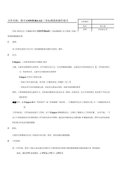
目的:指导安全.正确操作蔡司CONTURAG2三坐标测量机(以下简称三坐标)获得准确测量结果。
1范围:本工作指引适用于本公司三坐标测量机相关操作及使用、维护。
2定义:Calypso:三坐标所使用的专用测虽:软件元素:元素具有规则的几何形状,以不同的方式左义,可以用测量机测量。
元素包含几何形状的名义值,可用来评泄大小,形状和位苣。
元素可以分配给相关的特性Calypso中有以下两类元素:一类是工件自身的元素,如平面(平整的表而)和圆柱(孔)等一类是自身不存在的构建元素。
但此类元素是必须的,如相交线和圆柱轴等特性:工程制图需求的元素的尺寸,形状或位置的划义值及公差(例如:孔的直径,孔与平而的垂直度及两个平而之间的距离等)测量程序:是Calypso翻译“零件程序”或“控制数据”的结果。
一个测量程序包含了系统用于执行一个测量的所有信息。
工件坐标系:工件坐标系是基于工件的。
对于Calypso和测量机而言,它泄位了测量台上工件的位置。
安全平面:一个由六个而组成的安全区域用绕在工件及相关的夹具周围,通过此区域的设定以避免测针碰撞的危险。
探针在这些而组成的区域之外运动以避免碰撞。
3职责:计量室专职测量员负责三坐标的日常点检、保养、使用及输岀测量数据。
4工作流程:4」工作环境:使用三坐标之前先确认环境符合下面的要求以取得正确的测量数据及避免机器不必要的损耗:温度:18~22°C 温度梯度:1. 0°C/h 1.5°C/天1.0°C/米湿度:40~60%之间气压:4・8~5・2par (无水、无汕、无尘)电压:220V±10%4.2开机每日开机前用无尘布醯分析纯级无水酒精擦拭大理石平台上空气垫导轨的外露部分4.2.1打开配电箱电源和气阀,确认通电和工作气压。
4.2.2顺时针旋转以三坐标控制柜正而右上角的黑色旋钮至ON档。
4.23 顺时针旋转三坐标机身控制而板上而的黑色旋钮至RUN档,机器开始自检,机器控制面板和探头上的指示灯开始闪烁,指示灯停止闪烁后自检完成。
- 1、下载文档前请自行甄别文档内容的完整性,平台不提供额外的编辑、内容补充、找答案等附加服务。
- 2、"仅部分预览"的文档,不可在线预览部分如存在完整性等问题,可反馈申请退款(可完整预览的文档不适用该条件!)。
- 3、如文档侵犯您的权益,请联系客服反馈,我们会尽快为您处理(人工客服工作时间:9:00-18:30)。
断层分辨率
DEFORMATION宽度 深度转换 压力预测 区域应力确定 岩性预测和成图
数据质量改善
Standard processing
频率增强 改善迭加 改善断层分辨率 勘探足迹关注 改善井对地震数据的闭合
AZIM processing
办公室位置和联系方式
地址: 225 E. 16th Avenue, Suite 1200 Denver, CO 80203 电话: (303)318-7780
Bringing Geology and Geophysics Together
AXIS 地球物理公司提出革命性的新概念 IRP (INTERPRETATION_READY PROCESSING). 我们的 技术要把地质信息综合到地震数据处理中, 以建 立准备用于解释的地表一致性的地层成像. 不象传统的井闭合技术, AXIS 地球物理公 司在井和地震数据之间使用一种交互技术, 保持 精度高, 地质上与地震数据一致.
方位角速度变化特别在窄方位角放炮时, 将严重危害你的地震数据质量. AXIS公司的属性技术在市场上提供更精 确的方位角速度测量. 使用AXIS公司的AZIM 技术, 对方位角速度变化做适当的校正 对大量的 AVO 分析, 速度分析以及改善 数据质量打下坚实的基础.
AZIM 的产品和优点
方位角速度 Vfast-Vslow AVO 分析 截距和梯度数据体 方位角 AVO 数据体 AVO 误差分析 亮点分析 流体因子 第三项 AVO 分析 四阶时差分析 VTI 反演 裂缝检测
先进的解释处理
压力预测 高分辨率剩余速度分析 反演 井到地震属性校正 谱分解 地震属性成图 迭前成像
AZIM 处理
增强数据质量 精确的 AVO 和速度测量 第三项 (双曲线拟合) AVO分析 截距和梯度数据体
恢复数据
AXIS 地球物理公司革命性的新 AZIM 技术, 几乎在任何环境下改善数据质量. AZIM 技术定义在数据分析中新的分级. 如果你对质量好的数据, 精确的速度信息或 者任何类型的 AVO 分析感兴趣. 那么你应 该考虑 AZIM 处理技术应用于你的项目中.
Tel: (10) 84534350 Fax:(10) 84534351
Bringing Geology and Geophysics Together
我们的产品由于综合了处理技术的特点, 将 节省用户的时间, 降低成本. 大部分地球物理公 司提供的产品在做解释之前, 要求大量的数据和 条件. 一旦客户从AXIS 得到一个项目, 那么,井 和地震数据处理就保持一致. AXIS 地球物理公司所使用的交互技术, 不 仅得到好的成像,而且对你的数据的优点和缺点 给予更好的理解. IRP 处理技术使用户集中精力 做重要的事成, 那就是解释.
产品功能简介
用于解释的处理系统(IRP) 2D 和 3D 高分辨率地层成像 基于子波的属性处理 迭前3D 数据库合并 根据测井数据进行迭加QC 研究和参数试验 基于子波的时深功能 精确的井闭合和合成数据 大量的相位QC
地球物理测井解释
石油物理测井解释 声波测井标定 伪声波测井构建 横波处理和估算 区域石油物理模型 岩性模型 AVO 合成记录
传真: (303)318-7上海中心写字楼302 美国输入/输出公司北京代表处 电话: 68458445 84534347 传真: 84534351 Email: gmgbj@ 邮编: 100016 有关详细资料,请联系绿山公司:
