8-40W Ku-Band BUC 简体版中文手(99-09-20) V2
NETGEAR XS708E ProSafe Plus 10GBASE-T 8口10Gbps 网络开
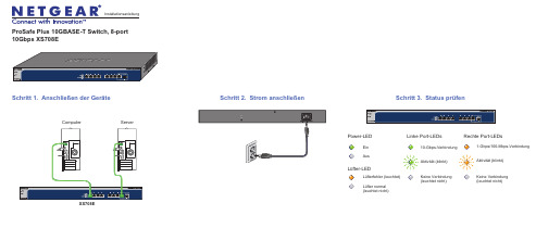
ProSafe Plus 10GBASE-T Switch, 8-port 10Gbps XS708ESchritt 2. Strom anschließen Schritt 1. Anschließen der Geräte XS708EComputer ServerEin AusPower-LEDAktivität (blinkt)Keine Verbindung (leuchtet nicht)10-Gbps-VerbindungLinke Port-LEDsRechte Port-LEDsLüfter-LEDLüfterfehler (leuchtet)Lüfter normal (leuchtet nicht)Aktivität (blinkt)Keine Verbindung (leuchtet nicht)1-Gbps/100-Mbps-VerbindungSchritt 3. Status prüfenNovember 2012Dieses Symbol wurde in Übereinstimmung mit der EU-Richtlinie 2002/96/EG zu Elektro- undElektronik-Altgeräten (WEEE-Richtlinie) hier angebracht. Die Entsorgung dieses Produkts innerhalb der Europäischen Union sollte in Übereinstimmung mit den in Ihrem Land zur Implementierung der WEEE-Richtlinie geltenden Gesetzen gehandhabt werden.NETGEAR, das NETGEAR Logo und Connect with Innovation sind Marken und/oder eingetragene Marken von NETGEAR, Inc. und/oder seiner Tochtergesellschaften in den USA und/oder anderen Ländern. Informationen können ohne vorherige Ankündigung geändert werden. Andere Marken- und Produktnamen sind eingetragene Marken oder Marken der jeweiligen Inhaber. © NETGEAR, Inc. Alle Rechte vorbehalten.In allen Staaten der EU, in EFTA-Staaten und in der Schweiz nur für die Verwendung in Räumen vorgesehen.Die vollständige EU-Konformitätserklärung finden Sie unter /app/answers/detail/a_id/11621/.Hinweis: Zur Verbesserung des internen Designs, des Betriebs und/oder der Zuverlässigkeit behält NETGEAR sich das Recht vor, die in diesem Dokument beschriebenen Produkte ohne vorherige Ankündigung zu ändern. NETGEAR lehnt im Zusammenhang mit dem Einsatz oder der Anwendung der hier beschriebenen Produkte oder Schaltpläne jegliche Haftung ab.Einrichten desSwitch-KonfigurationsprogrammsPlus-Switches sind plug-and-play-fähig. Sie können ein Konfigurationsprogramm installieren, um zusätzliche Optionen auszuwählen, mit denen Sie den Switchverwalten und für Ihr Netzwerk anpassen können. Dieses Dienstprogramm befindet sich auf der Begleit-CD, die Sie zusammen mit dem Switch erhalten haben.Hinweis: Das Konfigurationsprogramm ist auf dem Computer installiert und wird nur auf Windows unterstützt.Installieren Sie das Konfigurationsprogramm:1.Legen Sie die Begleit-CD in einen Computer ein, der an den Switchangeschlossen ist.2.Klicken Sie auf Install ProSafe Plus Utility , und folgen Sie den Anweisungen,um das Programm zu installieren.Das Switch-Konfigurationsprogramm wird in das Programmverzeichnis des Computers installiert, und auf dem Desktop wird ein ProSafe Plus Utility-Symbol erstellt.Konfigurieren Sie den Switch:1.Klicken Sie doppelt auf das ProSafe Plus Utility -Symbol.Plus-Switche, die das Gerät im lokalen Netzwerk ermitteln kann, werden auf der Konfigurations-Startseite angezeigt.2.Wählen Sie den Switch aus, der konfiguriert werden soll.Sie müssen nun das Passwort für den Switch eingeben. 3.Geben Sie dieses in das Passwort-Feld ein.Das Standard-Passwort ist password.4.Konfigurieren Sie den Switch nun mit dem Programm.Eine Beschreibung der Funktionen finden Sie im Benutzerhandbuch zum Thema Konfigurationsprogramm für ProSafe Plus Switch . DasBenutzerhandbuch befindet sich auf der Begleit-CD, aber Sie erreichen es auch über die Links im Hilfe-Bereich des Programms.Technische DatenTechnischer SupportNach der Installation des Geräts können Sie das Produkt unterhttps:// registrieren. Die Seriennummer finden Sie auf dem Etikett Ihres Produkts.Die Registrierung ist Voraussetzung für die Nutzung des telefonischen NETGEAR Supports. NETGEAR empfiehlt, das Gerät über die NETGEAR Webseite zu registrieren. Produkt-Updates und Support im Internet erhalten Sie unter .。
八线4X SDR InfiniBand 端口交换平台用户手册说明书
Eight 4X SDR InfiniBand Port Switch PlatformUser’s ManualPart Number: F-X430066Rev 1.012Eight 4X SDR InfiniBand Port Switch Platform User’s Manual3 ContentsContents 3List of Figures 5 Revision History 7 About this Manual 9 Chapter 1 Overview 11 Chapter 2 Installation and Basic Operation 122.1 Switch Platform Hardware Overview 122.1.1 InfiniBand Connectors 132.1.2 InfiniBand Port LEDs 132.1.3 System Status Indicators 132.1.4 I2C-compatible Bus Connector 132.2 Switch Platform Installation and Operation 132.2.1 Mechanical Installation 142.2.2 Power Connections and Initial Power On 142.2.3 InfiniBand Copper Cable Installation 142.2.3.1 Cable Length Support And IB Port Configuration 15 Chapter 3 Management Tools Overview 163.1 Updating Firmware 163.2 IB Administration 163.2.1 IBADM Requirements 173.2.2 How to Get IBADM 17 Appendix A Specification19 Appendix B Mechanical Drawing20 Appendix C Rack Adapter Installation Instructions21Rev 1.014Rev 1.01Eight 4X SDR InfiniBand Port Switch Platform User’s Manual5 List of FiguresFigure 1: Switch Front and Rear Panels12 Figure 2: Default Configuration Model (Example)16 Figure 3: Switch, Mounting Ears, Screws21 Figure 4: Rear Panel Side with Ear Screws Removed22 Figure 5: Mounting Ear Assembled on Rear Panel Side22 Figure 6: View of Rack Adapter Assembled on Rear Panel Sides23 Figure 7: View of Rack Adapter Assembled on Front Panel Sides23Rev 1.016Rev 1.01Eight 4X SDR InfiniBand Port Switch Platform User’s Manual7 Revision HistoryTable 1 - Revision History TableRevision & Date Description1.01 March 2006Added warnings to Section2.2.2, “Power Connections and Initial Power On,” on page141.00 February 2006First versionRev 1.018Rev 1.01Eight 4X SDR InfiniBand Port Switch Platform User’s Manual9 About this ManualThis manual provides an overview of the Eight 4X SDR InfiniBand Port Switch system and guidelines for its opera-tion. Specifically, it covers the following product:Table 1 - Switch Products Covered in this User’s ManualProduct Number DescriptionF-X430066Eight 4X InfiniBand Port Switch PlatformIntended AudienceThis manual is intended for users and system administrators responsible for installing and setting up the switch plat-form listed above.The manual assumes familiarity with the InfiniBand™ architecture specification.Rev 1.0110Rev 1.01Eight 4X SDR InfiniBand Port Switch Platform User’s Manual11 1 OverviewThis User’s Manual provides an overview of the Eight 4X InfiniBand Port Switch System based on Mellanox Tech-nologies’ MT43132 InfiniScale switch device.The switch platform comes pre-installed with all necessary firmware and configuration for standard operation in an InfiniBand fabric running an InfiniBand compliant Subnet Management software in the subnet. All that is requiredfor normal operation is to follow the usual precautions for installation and connection to the fabric. Once connected, the Subnet Management software automatically configures and begins utilizing the switch.Basic installation and hardware maintenance is covered in “Installation and Basic Operation” on page12. Maintenance and configuration of the switch is done In-Band through the InfiniBand fabric using the IBADM tools package. This package provides the ability to monitor the temperature, voltage, port utilization, and other status parameters in the switch. To upgrade switch firmware, the MFT package is required. See “Management Tools Over-view” on page16.Installation and Basic Operation122 Installation and Basic Operation2.1 Switch Platform Hardware OverviewFigure 1 shows the front and rear panel views of the Eight 4X Ports Switch System, including the I 2C connector and status LEDs.Rear PanelI2C-compatible BusConnectorFront PanelStatusLEDsIB Port 8IB Port 1Figure 1: Switch Front and Rear PanelsLink LEDEight 4X SDR InfiniBand Port Switch Platform User’s Manual132.1.1 InfiniBand ConnectorsAll InfiniBand connectivity is via the rear panel. Figure1 shows the eight 4X InfiniBand port connectors. Each port also includes power supply functionality to support fiber media adapters.2.1.2 InfiniBand Port LEDsTwo IB port LEDs are located to the left of each IB port connector on the rear panel (see Figure1 on page12). The lower (Green) LED is the IB port Physical link LED, and the upper (Yellow) LED is the IB port Logical link LED (Activity LED).Physical Link LED (Green) indications:•Steady On:The Physical link is established•Off:Physical link error, poor connection quality, or no physical connectionActivity LED (Yellow) indications:•Steady On:The Logical link is up but there is no data transfer•Blinking:Data is being transferred to/from the switch port across the cable wires•Off:The Logical link is down2.1.3 System Status IndicatorsTwo system status indicators are located on the left of the rear panel and are labeled “Status” (see Figure1 onpage12). The following status conditions are possible:1.SYSTEM STATUS OK: Green ON, Yellow OFF2.TEMPERATURE ALARM: Yellow ON3.SYSTEM OFF: Green OFF, Yellow OFF4.POWER CIRCUIT ERROR: Green OFF, Yellow OFF (with the power cord connected to power)2.1.4 I2C-compatible Bus ConnectorThe I2C-compatible Bus connector is for factory and development use only.The connector is a female 9 pin D-Type connector. Table1 shows the pinout functions:Table 1 - I2C-compatible Bus Connector Pinout FunctionsPin Number Function1-5GND6SDA8SCL7, 9Not Connected2.2 Switch Platform Installation and OperationInstallation and initialization of the switch platform are straightforward processes, requiring attention to the normal mechanical, power, and thermal precautions for rack-mounted equipment. The switch platform does not require any programming or configuration to operate as a basic InfiniBand switch and includes all of the necessary functionality to operate with external standard InfiniBand Subnet Management software.Installation and Basic Operation14This section describes the installation process and basic operation of the switch platform.2.2.1 Mechanical InstallationThe switch platform is packaged in a 1U chassis. See Table 2, “Switch Platform Mechanical and Environmental Requirements (Worst Case, Fully Populated Chassis)”. If the switch is to be mounted in a standard 19” rack it will require an adapter. Two ear brackets are included (but not assembled) in the packing box of the switch system, which can be assembled on the sides of the chassis acting as the 19” rack adapter, and include rack mounting holes which conform to the IEA-310 standard for such a rack. See “Rack Adapter Installation Instructions” on page 21.Note:The installer should use a rack cable to support the mechanical and environmental charac-teristics of a fully populated switch Chassis as listed in Table 2.Proper ventilation should also be guaranteed for air intake at the front of the chassis and exhaust at the rear in order to maintain good airflow at ambient temperature. Cable routing in particular should not impede the air exhaust from the chassis.Note that the switch platform can be either front or rear mounted. The notion of “front” and “rear” is arbitrary; how-ever, “rear” is used consistently in this manual to refer to the side of the chassis with the InfiniBand connectors.2.2.2 Power Connections and Initial Power OnWarning: The switch platform will automatically power on when AC power is applied. There is no power switch. Make sure the power cable is properly plugged into the system before connecting to power.Warning: The switch platform must be connected to an earthed mains socket-outlet.Warning: In Norway, this system should be connected to the IT power distribution system only .The input voltage is auto-adjusting for a 100-240 V AC, 50-60Hz power connection. The power cord should be a stan-dard 3-wire AC power cord including a safety ground and rated for 2A or higher.2.2.3 InfiniBand Copper Cable InstallationThe switch platform uses industry standard 4X InfiniBand cables which are available from several vendors. The stan-dard 4X cables support full-duplex 10Gb/s wire speed for all switch platform ports. All cables can be inserted or removed with the unit powered on. To insert a cable, press the connector onto the port receptacle until the connector is firmly seated. The GREEN LED indicator to the left of each port will light when the physical connection is estab-lished (that is, when the unit is powered on and a cable is plugged into the port with a functioning port plugged into the other end of the connector). After plugging in a cable, lock the connector using the latching mechanism particular to the cable vendor. To remove, disengage the locks and slowly pull the connector away from the port receptacle. Both LED indicators will turn off when the cable is unseated.Table 2 - Switch Platform Mechanical and Environmental Requirements (Worst Case, Fully Populated Chassis)Rack HeightRack Width Rack Depth Weight Power Ambient Temp.1U12.4”(315mm)w/o Rack Adapter 6.9”(175mm)7.7lb (3.5Kg)45WSingle 100-240 V AC 50-60HzInputMax: 50ºC Min: 0ºC19” (EIA-310)(483mm)w/ Rack AdapterEight 4X SDR InfiniBand Port Switch Platform User’s Manual15Warning:Care should be taken not to impede the air exhaust flow through the ventilation next to the InfiniBand ports. Cable lengths should be used which allow for routing horizontally around to the side of the chassis before bending upward or downward in the rack.2.2.3.1 Cable Length Support And IB Port ConfigurationThe switch platform is configured to drive cables up-to 20 meters long. This configuration allows maximum flexibil-ity in building a robust IB cluster.The selected configuration and cables should meet the required BER specified in the InfiniBand Architecture Specifi-cation, Volume 2, release 1.2.Management Tools Overview 163 Management Tools Overview3.1 Updating FirmwareIn order to update switch firmware, the MFT tools package is needed by Mellanox Technologies. To download this package, visit /support/switch_firmware_table.php. Make sure to also download the MFT User’s Manual and Release Notes. Specifically, the ‘spark’ tool of the MFT package is required for firmware updates. Please see the MFT User’s Manual for details.The most updated firmware is also available for download from the same web page above. Please find the ‘Custom Switch based on Mellanox's MT43132 InfiniScale switch device’ entry in the firmware table.3.2 IB AdministrationTo monitor status conditions in the switch platform, the IBADM tools package is needed (by Mellanox Technolo-gies). IBADM enables the system administrator to manage one or more switch platforms from a single remote Infini-Band host. The features include the following:•Full In-Band Management of Multiple Switch and HCA Systems from single host1•Simple default configuration to get started quickly•Name-based subnet browsing and topology verification•Event monitoring of port statistics, link status and system status for all ports in the switch•Checking and updating the firmware•Intuitive CLI interface•Extensible and customizableThe figure below shows the default configuration model for these tools:Figure 2: Default Configuration Model (Example)One or more switches InfiniBand HCA1.Firmware updates to this Eight 4X IB Port Switch System cannot be performed using ibfwmgr (the burning tool of IBADM pack-age). See Section3.1, “Updating Firmware,” on page16.Eight 4X SDR InfiniBand Port Switch Platform User’s Manual173.2.1 IBADM RequirementsThe general requirements for installing the IBADM software are listed below. Please see the IBADM release notesfor details on platform, OS, Driver and Subnet Management support.puter Platform with an InfiniBand HCA card installed12.HCA Driver3.InfiniBand Compliant Subnet Management. The Open Source SM (Eponyms) is supported.3.2.2 How to Get IBADMPlease visit Mellanox Technologies’s Documents Distribution System at . The IBADM package is available for download under ‘Code Releases/ Tools’. Note that access requires a customer login account. Consult your sales representative for details.1.Any Mellanox Technologies HCA card can be used. Consult your sales representative for other possibilities.Management Tools Overview 18Eight 4X SDR InfiniBand Port Switch Platform User’s Manual19 Appendix A: SpecificationTable 3 - Specification DataPhysical Power and EnvironmentalSize (HxDxW): Size with Rack AdapterWeight:Mounting: 10Gb/s Connector:1U x 6.9” x 12.4” (43.6mm x 175mm x 315mm)1U x 6.9” x 19” (43.6mm x 175mm x 482.6mm)7.7lb (3.5kg)19” RackmountInfiniBandInput V oltage:Maximum Power:Ambient Temperature:Humidity:Altitude:Shock:Vibration:Internal V oltage:100-240 V AC 50-60Hz45W0ºC to 50ºC10% - 90% non-condensing+5 VDCProtocol Support Regulatory ComplianceInfiniBand:QoS: RDMA Support: Management:10Gb/s8 InfiniBand Virtual Lanes for all portsYes, All PortsPerformance, and Device managementAgents for full InfiniBand In-Band Manage-mentSafetyEMCScalability and Performance Reliability, Availability and Serviceability FeaturesSwitching Performance:Addressing:Simultaneous wire-speed any port to any port48K Unicast Addresses Max. per Subnet16K Multicast Addresses per SubnetHot-Swappable:N+1 Redundant:NoneNone20Appendix B: Mechanical Drawing21Appendix C: Rack Adapter Installation InstructionsC.1 Rack Adapter Assembly PartsThe rack adapter assembly parts are included in the switch packing box and are listed in Table 4:C.2 Assembling the Rack AdapterSTEP 1:Remove the pair of screws from the two sides of the chassis where the rack adapter is to be installed. See Figure 4 on page 22.Note: The rack adapter can be installed on the sides close to the front panel or to the rear panel.Table 4 - Rack Adapter Assembly PartsItem QuantityNotes Mounting Ear2See Figure 3Phillips 100° Flat Head, Passivated Stainless SteelUNC Screw 4-40 x ¼2Each mounting ear requires 3 screws. Two additional pairs ofscrews are to be found assembled on the switch chassis sides.Figure 3: Switch, Mounting Ears, ScrewsSTEP 2:Assemble the rack kit as shown in Figure 5.See also Figure 6,“View of Rack Adapter Assembled on Rear Panel Sides” and Figure 7, “View of Rack Adapter Assembled on Front Panel Sides,” on page23.Figure 4: Rear Panel Side with Ear Screws RemovedFigure 5: Mounting Ear Assembled on Rear Panel Side23Figure 6: View of Rack Adapter Assembled on Rear Panel SidesFigure 7: View of Rack Adapter Assembled on Front Panel Sides。
易苏里奥无线开发套件(AN008)用户手册说明书
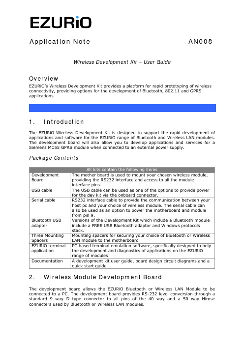
Application Note AN008 Wireless Development Kit – User GuideOverviewEZURiO’s Wireless Development Kit provides a platform for rapid prototyping of wireless connectivity, providing options for the development of Bluetooth, 802.11 and GPRS applications1. IntroductionThe EZURiO Wireless Development Kit is designed to support the rapid development of applications and software for the EZURiO range of Bluetooth and Wireless LAN modules. The development board will also allow you to develop applications and services for a Siemens MC55 GPRS module when connected to an external power supply.Package ContentsDevelopment Board The mother board is used to mount your chosen wireless module, providing the RS232 interface and access to all the module interface pins.USB cable The USB cable can be used as one of the options to provide power for the dev kit via the onboard connector.Serial cable RS232 interface cable to provide the communication between your host pc and your choice of wireless module. The serial cable canalso be used as an option to power the motherboard and modulefrom pin 9.Bluetooth USB adapter Versions of the Development Kit which include a Bluetooth module include a FREE USB Bluetooth adaptor and Windows protocols stack.Three Mounting Spacers Mounting spacers for securing your choice of Bluetooth or Wireless LAN module to the motherboardEZURiO terminal application PC based terminal emulation software, specifically designed to help the development and diagnostics of applications on the EZURiO range of modulesDocumentation A development kit user guide, board design circuit diagrams and aquick start guide2. Wireless Module Development BoardThe development board allows the EZURiO Bluetooth or Wireless LAN Module to be connected to a PC. The development board provides RS-232 level conversion through a standard 9 way D type connector to all pins of the 40 way and a 50 way Hirose connecters used by Bluetooth or Wireless LAN modules.A separate connector is provided for PCM audio for use with the 40 way EZURiO Bluetooth modules. This can be connected to a customer’s own evaluation board or a range of codec accessory boards that EZURiO will make available.3.Getting to know the Development Board40 way connector50 way connector9 way DEERS-232 Level ShifterPSU Options:USB 2.1mm JackScrews orReset SwitchPCM Output4. Power SupplyMinimum Typical Maximum Input Voltage3.6V5V6VThe development board provides a number of options to provide power to the module.• 5V Power from a USB port• Power from an external power supply via screw terminals• Power from a external mains power block via a 2.1mm DC connector • Power via Pin 9 of the RS232 adaptorThe developer kit includes a USB cable to provide power to the development board. This should be plugged into a PC USB port, a USB hub, or a mains adaptor with a USB output. If a hub is used, it should be a powered USB hub to ensure that sufficient current is available at the port being used. Both the Bluetooth Intelligent Serial Module (BISMII) and the Wireless LAN (WISM) modules can be driven by the current available at a USB port.When using a Siemens MC55 GPRS modem in the development board, an external power supply with a minimum current capacity of 2A MUST be used and connected to the power supply terminals.Jumper JP2 is used to select an external power source on the screw terminals.SW1 (slide switch) provides the power on / off for the module but does not isolate the power from other components of the development board.S1 (push button TACT switch) provides a reset signal to both the 40 way and 50 way connectors. Note that the reset polarity is different for the 40 and 50 way pinouts. This is accomplished by circuitry on the development board, providing an active HIGH reset for the 40 way connector and an active LOW for the 50 way connector. Users connecting a reset signal to the test points one the board, should be aware that there is a 10kΩpulldown on the 40 way reset pin, and a open collector transistor connected to the 50 way reset pin. Refer to the schematics on the CD.An alternative method of powering the development kit is to supply power to Pin 9 of the RS232 connector. If this method is used, no other power supplies should be connected to the board. Jumper 8 on the development board needs to be moved to allow power to be derived from pin 9 of the serial port. In this mode the ring indicator will not be available from the RS232 interface.5.RS-232 Serial InterfaceThis provides a direct interface to any standard RS-232 port on a PC or peripheral. The 9 way D type connector can be plugged straight into a serial port on a PC or peripheral. If access to the serial port is restricted, the serial cable provided can be used to connect the development board to the PC.The development board contains a level shifter on the RX, TX, CTS, RTS, DTR, DSR, RI and DCD signals that converts between the 3.3V levels required on the module to the standard RS-232 levels.The level shifter can have its outputs permanently enabled, or enabled only when themodule is active, i.e. not in sleep mode. The latter is useful when a defined state is required at the RS232 interface as the module enters and exits its low power modes.The behaviour is determined by the setting of J10, which is located behind the USB socket at the rear of the board. The normal setting is Always Enabled.Note that the 50 pin formats of the WISM and the Siemens MC55 do not support the output line to drive this input. When using modules on the 50 pin connector J10 must be set to Always Enabled.J10 SettingsIf digital signal levels are required at the RS232 connector, these can be achieved by removing the level shifter and populating the PCB pads that are then exposed with zero ohm links.6. SoftwareThe development board will connect any EZURiO Bluetooth or Wireless LAN Module to theserial port of a PC or other device. From a PC you can communicate with the module using any Terminal Emulator software such as HyperTerminal, Procomm or the EZURiOTerminal application supplied.EZURiO Terminal is a terminal emulation application capable of running on Windows 98, Me, 2000 and XP operating systems. It was developed specifically to aid development and testing of EZURiO Modules. It allows connection to serial devices using any combination of the following communications parameters:COM Port: 1 to 255Baud rate: 300 to 921600Parity: None,EvenOdd,Data Bits: 7 or 8Stop Bits: 1 or 2CTS/RTSHandshaking: NoneorThe benefits of using EZURiO Terminal are:•Status of DSR, CTS, DCD and RI are continuously displayed•DTR on the host PC can be directly controlled via a check box•RTS can be directly controlled•BREAK signals can be sent•Scripts can be run to assist•Additional built-in features speed developmentEZURiO includes a “Data Transfer Test” mode allowing data to be sent as fast as the handshaking will permit. This feature is useful for testing the bit transfer rate of a Bluetooth connection.The EZURiO terminal application is provided on the CD within this kit; updates are also available from our website: 7. Interface Specification7.1 Serial port connectorThe pin-out for the 9 way D type connector is shown in the table below.Note: The direction is as seen from the Module’s perspective.Pin Description Signal Direction1 Data Carrier Detect DCD Output2 Transmit Data TD Output3 Receive Data RD Input4 Data Set Ready DSR Input5 Ground GND ---6 Data Terminal Ready DTR Output7 Clear To Send CTS Input8 Request To Send RTS Output9 Board Power or Ring Indicator RI or Power Output7.2 Module Breakout connectorsAll of the pins from the 40 way and 50 way connectors, WITH THE EXCEPTION OF Vccare available on each of two rows of plated through holes on the long sides of the board. These translate directly to the pin layout of the module receptacles, allowing access to all of the module pins. Pin 1 is indicated by an ident on the silk screen.The format of the holes allows the fitting of your choice of connectors, or they can be used for directly soldering test wires to the board. Both are laid out on a standard 0.1” (2.54mm) pitch.7.3 PCM InterfaceThe Development board provides a dedicated audio interface for the Bluetooth modules. The pins provide the developer with access to the module’s PCM lines as well as providing power to allow additional audio hardware to be developed. EZURiO has developed a range of audio codec interface boards that can be plugged directly onto this interface to support audio application development.7.4 Board configuration jumpersJumper DescriptionJP1 Breaks the supply to the module for current measurementsJP2 Selects external power supply for Siemens modulesJP8 Selects pin 9 powerJ10 Selects low power mode for RS-232 level shifter8. Other Features8.1 Power Consumption MeasurementA removable jumper JP1 is provided to break the supply line directly to the modules, allowing the current consumption to be measured. For normal operation JP1 must be fitted.Note that this only measures the current consumption of the module, and not of the level shifter or other peripheral circuitry.8.1 USB AccessUSB access can be provided to allow a direct USB connection to a Bluetooth HCI module. To do this remove resistors R17 and R18 from the development kit and replace them with zero Ohm links.Note that if this is done and the unit is then connected to a USB host port, it will be powered from that same port. Do not attempt to use any other power source for the development kit when operating in this mode.This is not relevant for modules with a UART interface.9. WarrantyEZURiO warrants that its products shall conform to EZURiO’s published specifications and remain free from defects in materials and workmanship under normal, proper andintended use for a period of two (2) years from date of purchase, provided that proof of purchase be furnished with any returned equipment.If during the warranty period any component part of the equipment becomes defective by reason of material or workmanship, and EZURiO is immediately notified of such defect, EZURiO shall at its option supply a replacement part or request return of equipment, freight prepaid, to its designated facility for repair. In the event no trouble is found on products returned for repair, EZURiO reserves the right to charge the customer its standard published repair charge.This warranty shall not apply to any products that have been subject to misuse, bending, twisting, neglect, alteration, improper installation, testing or unauthorized repair performed by anyone other than an EZURiO designated repair facility. Any non-warranty repairs or maintenance shall be at EZURiO’s standard rates in effect at the time.This warranty is in lieu of all other warranties, whether expressed, implied, or statutory, including but not limited to, implied warranties or merchantability and fitness for a particular purpose. In no event shall EZURiO be liable, whether in contract, in part, or on any other basis, for any damage sustained by its customers or any other person arising from or related to loss of use, failure or interruption in the operation of any products, or delay in maintenance, or for incidental, consequential, in direct, or special damages or liabilities, or for loss of revenue, loss of business, or other financial loss arising out of or in connection with the sale, lease, maintenance, use, performance, failure, or interruption of these products.EZURiO LtdSaturn House, Mercury ParkWycombe Lane, Wooburn Green, HP10 0HHUnited KingdomTel: +44 1628 858 940Fax: +44 1628 528 382The information contained in this document is subject to change without notice. EZURiO Ltd makes no warranty of any kind with regard to this material including, but not limited to, the implied warranties of merchant ability and fitness for a particular purpose. EZURiO Ltd shall not be liable for errors contained herein or for incidental or consequential damages in connection with the furnishing, performance, or use of this material.© Copyright 2007 EZURiO Limited. All rights reserved. No part of this document may be photocopied, reproduced, or translated to another language without the prior written consent of EZURiO.BLUETOOTH is a trademark owned by Bluetooth SIG, Inc., U.S.A. and licensed to EZURiO Ltd.All other trademarks are the property of their respective owners.The information contained within this Application Note is provided as a guide and is subject to change.。
台电U盘工具
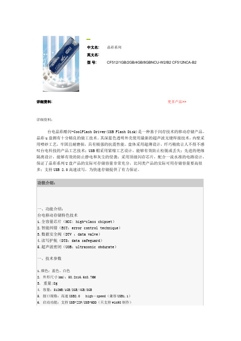
中文名:晶彩系列
英文名:
型号:CF512/1GB/2GB/4GB/8GBNCU-W2/B2 CF512NCA-B2
详细资料:更多产品>>
详细资料:
台电晶彩酷闪-CoolFlash Driver(USB Flash Disk)是一种基于闪存技术的移动存储产品。
晶彩u盘拥有十分精良的做工技术。
其深蓝色透明外壳使用最新的超声波无缝焊接技术,内壁采用喷砂工艺,牢固且耐磨损,具有极强的抗震性能。
盘体采用超薄设计,纤巧精致让人不得不感叹台电科技的产品工艺技术;USB帽采用紧缩工艺设计,能够有效防止松脱或丢失;先进的绝缘隔离设计,能够有效的防止静电和灰尘的侵袭;采用顶级闪存芯片,配合一流水准的电路设计,保证了晶彩系列U盘产品的实际可存储容量非常充分,比同类产品的实际可用存储容量要高很多;支持USB 2.0高速读写,为快速存储提供了有力保证。
晶彩(NCU)系列驱动程序
专用于晶彩NCU系列WIN98驱动程序及启动、分区、加密制作工具(支持Vista),适用于全系列(注:从包装彩盒右侧面型号贴纸上可查到产品名称)如:CF4GBNCU-B2
LOCK登入程序
此程序主要解决用户将LOCK程序删除后的解决方法,目前适用于欣喜(晶喜)系列、晶灵II代系列、晶彩系列、晶致系列、欣悦系列产品、晶灵III代系列
酷闪修复工具
此修复工具仅适合以下系列:晶彩系列、晶灵II代、天志系列、晶致系列、欣悦系列、欣喜(晶喜)系列、风尚系列、晶灵III代。
WX-08U2用户手册说明书

User Manual Ver0.1 TPC-WX08U28寸人脸支付平板ARM Cortex™_A17架构RK32881.8GHz CPU8”LCD触控式电容屏2G内存,8G EMMC电子盘1x RJ45GbE LAN,1x RS232COM1x MICRO USB,2x USB2.0Port1x Mini SD卡座,1x SIM卡座支持3G/4G通讯、内置蓝牙+WIFI模块支持DC-12V电源输入版权声明随附本产品发行的文件为深圳市英康仕电子有限公司2019年版权所有,并保留相关权利。
针对本手册中相关产品的说明,深圳市英康仕电子有限公司保留随时变更的权利,恕不另行通知。
未经深圳市英康仕电子有限公司公司书面许可,本手册所有内容不得通过任何途径以任何形式复制、翻印、翻译或者传输。
本手册以提供正确、可靠的信息为出发点。
但是深圳市英康仕电子有限公司公司对于本手册的使用结果,或者因使用本手册而导致其它第三方的权益受损,概不负责。
认可声明Rock chip为瑞芯微的商标。
ARM为ARMLtd.的商标。
.所有其它产品名或商标均为各自所属方的财产。
如需技术支持和服务,请访问深圳市英康仕电子有限公司网站:产品质量保证(1年)从购买之日起,英康仕为原购买商提供1年的产品质量保证。
但对那些未经授权的维修人员维修过的产品不予提供质量保证。
英康仕对于不正确的使用、灾难、错误安装产生的问题有免责权利。
如果英康仕产品出现故障,在质保期内我们提供免费维修或更换服务。
对于出保产品,我们将会酌情收取材料费、人工服务费用。
请联系相关销售人员了解详细情况。
如果您认为您购买的产品出现了故障,请遵循以下步骤:1.收集您所遇到的问题信息(例如,CPU主频、使用的英康仕产品及其它软件、硬件等)。
请注意屏幕上出现的任何不正常信息显示。
2.打电话给您的供货商,描述故障问题。
请借助手册,产品和任何有帮助的信息。
3.如果您的产品被诊断发生故障,请从您的供货商那里获得RMA(Return MaterialAuthorization)序列号。
惠威HR70遥控器使用说明书
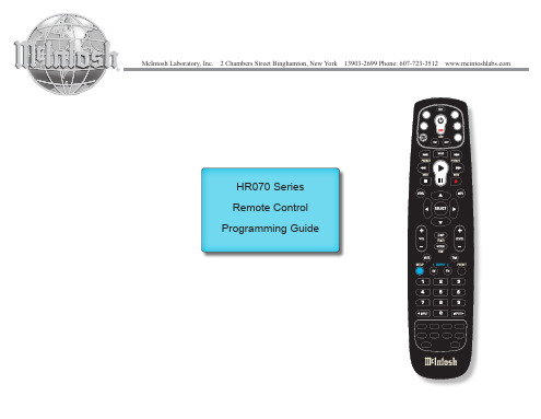
HR070 Series Remote Control Programming Guide
6. Repeat steps 1 to 5 for the other components you want to control. For future reference, write down each working component code below:
HR Series Remote Control Programming
Assigned Push-button Component Program Code
TV
CBL
SAT
AUX
DVR
Push-buttons available for Programming
Flashes during Programming
4
Used to activate Programming Mode
with the most popular code first. If the component
responds, go to step 7.
6. If the component does not respond, press LEVEL+
Push-button and the Remote Control will test
The HR70 Series Remote Controls have stored in permanent memory the necessary information to send the correct commands to the component to be controlled. By entering a five digit numeric code the commands for controlling the component is activated.
WAVESTREAM 8_16_25_32_40 Ku-band BUC中文手册
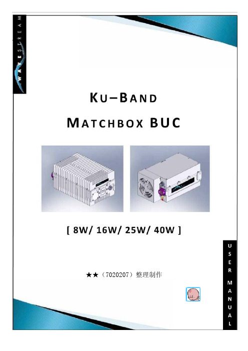
★★★★(7020207)整理制作目录1、引言 (3)1.1、保修 (3)1.2、技术支持 (3)1.3、设备维修服务 (3)1.4、注意事项 (3)2、安全 (5)2.1、避免水和连接器上的水分 (5)2.2、保证设备通风 (5)2.3、使用正确的电源 (5)2.4、防止雷击和电源浪涌 (6)2.5、禁止往设备内插如异物 (6)3、系统描述 (7)3.1、空间功率合成 (7)3.2、接口与外形尺寸 (8)3.2.1、“IF IN”连接器(J1) (8)3.2.2、“RF OUT”连接器(J2) (8)3.2.3、DC和监控(J3) (8)3.2.4、LED指示灯 (11)3.2.5、安装面尺寸 (11)3.2.6、风扇 (14)3.2.7、监控电缆 (14)4、连接和配置功放 (15)4.1、设备开箱 (15)4.2、配件,可能附带以下配件以协助单元的安装: (15)4.3、检查设备的接口 (15)4.4、检查配套电缆 (15)4.5、将本装置安装 (16)4.6、启动发射开关 (16)5、技术参数: (17)6、维护与保养 (20)6.1、一般性维护 (20)6.2、风扇组件的更换 (20)7、规范与标准 (21)7.1、标准规定认证 (21)7.2、EC符合性声明 (21)8、故障诊断 (22)8.1、两个LED灯不亮,风扇转 (22)8.1.1、首先检查功放TX为启用状态 (22)8.1.2、然后确认IF输入和RF输出 (22)8.2、两个LED灯不亮,风扇也不转 (22)8.2.1、首先确认供电航空头有直流电 (23)8.2.2、然后检查DC和M&C航空头连接是否充分。
(23)8.3、“LOL”黄灯亮 (23)8.3.1、首先确认调制器10MHz (23)8.3.2、然后检查连接 (23)8.4、“SUM FLT”红灯亮 (23)8.4.1、首先检查风扇和通风 (23)8.4.2、通过监控查看温度 (23)1、引言本用户手册提供的信息和指示的WAVESTREAM设备的安装和操作。
BONDTECH Ender-7 LGX Lite 和 Mosquito 安装指南说明书

Manuals+— User Manuals Simplified.BONDTECH Ender-7 LGX Lite And Mosquito On The Creality Owner’s ManualHome » BONDTECH » BONDTECH Ender-7 LGX Lite And Mosquito On The Creality Owner’s ManualContents1 BONDTECH Ender-7 LGX Lite And Mosquito On TheCreality2 HOW TO Install3 TAKE GOOD CARE OF IT4 HOW TO GET HELP5 Documents / Resources5.1 ReferencesBONDTECH Ender-7 LGX Lite And Mosquito On The Creality7. Loosen the three M3 screws holding the extruder to the motor using a 2 mm hex key.Pull away the extruder gear.Fasten the three M3 screws holding the extruder to the motor.Undo the four M3 screws on the bottom of the gantry front side using a 2 mm hex key.11. Undo the four M3 screws on the bottom of the gantry back side using a 2 mm hex key.12. Use a flathead screwdriver or something similar to pop off the gantry cowling.13. Cut the zipties securing the wire loom coming from the toolhead.14. Disconnect all wires coming from the toolhead.15. Pull the toolhead wiring loom through the gantry cowling.16. Undo the two M3 screws holding the toolhead to the x-carriage using a 2.5 mm hex key.17. Remove the wires from the conduit.18. Undo the two M3 screws holding the fan using a 2 mm hex key.19. Undo the four M3 screws holding the hotend using a 2 mm hex key.20. Add the conduit holder to the LGX lite using two low profile M3x8 screws and a 2 mm hex key.21. Add the mount to the bottom of the LGX lite using three low profile M3x8 screws.22. Add the mount to the hotend using two M2.5×6 SHCS screws and a 2 mm hex key.23. Add the included 40 mm PTFE insert and a collet clip.24. Remove the heater cartridge and thermistor from the original hotend and add to the Mosquito.25. Route wires as shown.26. Add the LGX lite and hotend to the x-carriage by pushing them from the front.27. Fasten the hotend to the x-carriage using included low profile M3x8 screws and a 2 mm hex key.28. Fasten the fan to the hotend using the included M2.5×16 screws and a 2 mm hex key.29. Fasten the cowling to the x-carriage back using the same SHCS screws and a 2.5mm hex key.30. Push and pull the wiring loom through the conduit.31. Using some tape and a spare piece of filament or string helps with this step.32. Secure the conduit to the side of the LGX lite using the two included zip ties.33. Place the gantry cowling loosely on the gantry and feed the conduit into it.34. Reconnect all the connectors unplugged previously.35. Click the gantry cowling back in place and secure it using the same screws on the back.36. Attach the bowden tube.’37. Unscrew all screws holding the bottom cover on.38. Remove the bottom cover.39. Power on the printer and be careful around the now live wires during the following step.40. With a multimeter, measure between PSU ground and the extruder trimpot.It should be aboout 1.25 volts from factory. Dial this down to 0.90 volts.41. Power it down and close it back up and you are done with the hardware configuration.Please see the Quick Start Guide for software configuration and print profiles.TAKE GOOD CARE OF ITEvery 6 months, or sooner if you have a higher than 15h per week average usage, perform the following maintenance operations:1. With a tooth brush and alcohol:a. Clean the double gear and the drive gearsb. Clean the needle bearings2. With a fine brush and lubricanta. Lubricate the needle bearings3. With compressed aira. Blow the housing plastic parts to remove dust and dirt particlesHOW TO GET HELPWe are available to help you with any questions or issues you may have. Simply go to our website where you can access our customer support and send us your questions or follow the provided link:https://www.bondtech.se/contact/#tab_technical-support-requestswww.bondtech.seDocuments / ResourcesBONDTECH Ender-7 LGX Lite And Mosquito On The Creality [pdf] Owner's ManualEnder-7 LGX Lite And Mosquito On The Creality, Ender-7, LGX Lite And Mosquito On The Creality, Lite And Mosquito On The Creality, And Mosquito On The Creality, Mosquito On The Creality, On The Creality, The CrealityReferencesBondtech Dual Drive Extruders and Extrusion Upgrade KitsContact Bondtech for support or to send us a messageManuals+,。
k8+电子中文说明书

用户指南User’Guide感谢:亲爱的用户感谢您购买我公司产品。
此份为用户操作指南,为了确保您快速方便的使用,在使用前请仔细阅读说明书。
目录:1.注意事项2.随机配件3.硬件规格4.认识产品5.开机和关机6.桌面7.按键8.系统设置*WIFI无线连接*声音*时间日期设置*屏幕待机9.安装、删除和运行应用程序10.触摸校准11.音乐12.视频13.图片14.网络15.录音16.照相17.电子市场18.邮件客户端19.壁纸20.外接设备*USB连接*OTG使用*键盘鼠标21.固件升级22.常见问题处理注意事项:﹡本产品是高精密度电子产品,请勿自行拆卸。
﹡避免强烈摔打,碰撞本产品。
﹡避免在以下环境中使用本产品:高低温、潮湿、多尘、磁场强大以及长期暴露于阳光之下。
﹡请使用拧干的湿棉布轻轻擦拭本产品外壳,严禁使用其他化学溶液清洗。
本产品不应水滴或水溅,所以产品附近不宜放置诸如水杯一类的装满液体的物品。
﹡过长时间、过大音量使用耳机可能会对听力造成永久性的伤害。
﹡请勿在穿越马路、驾驶机动车辆或者自行车时使用耳机,以免发生交通事故。
﹡请仅仅使用允许的电池、充电器和配件,使用任何其他类型的产品将违反保修条例,并有可能发生危险。
﹡请按照当地相关的环保条例来处理废弃机器和配件。
﹡本产品在使用过程中如有任何问题,请联系当地的经销商或直接与本公司客户服务中心联系。
﹡对于那些因为产品损坏、维修或者其他原因引起的抹涂内存损失,本公司不负任何责任,请用户遵照使用手册进行规范操作,并及时备份。
随机配件:(相关示意图)MID 主机5V 2A直流充电器快速入门指南保修卡USB 连接线硬件规则:开机和关机:﹡开机:按住电源键,系统将进入开机过程,如下所示:开机Logo启动过程中…系统已经启动,正在进入Android系统:之后,系统进入默认的主界面。
﹡关机:长按电源键,弹出设备选项,选择关机,如下所示:点击确认就可以安全关机。
﹡休眠:在机器正常运行状态下,短按电源键,进入休眠状态,此时,屏幕将会关闭。
DSUB-connect-standard

35
3.9
360~450
0.0014
AMOCO
1013
1.4*1016
130
3.9
450
0.032
XAREC
8*1014
3*1016
120
3.8
540
0.001
ARLEN
1015
1016
140
4
480
0.013
DuPont
1015
1016
145
4.2
580
0.016
DuPont
1014
1016
120
Tyco/Molex/FCI/Foxconn 安费诺/JAE/HRS/NAIS/京瓷
返回目录
分类 I
连接器的分类 I
依结构形状
圆形 矩形 印刷配线板(PWB)
依使用频率
低频(3MHz以下) 高频(3MHz以上)
高低频混装
依使用条件
室用/耐湿/防水/气密/ 耐火/防爆/耐幅射
依用途
军用/商用
连接器的分类 II
LCP Liquid crystal polymer
PCT Polycycolhexaylene terephthalate
PPA Polyphenyl amide
PC/ABS Polycarbonate/ Acrylonitrile-Butadiene-Styrene
PVC Polyvinyl chloride
聚氯乙烯
对位聚苯乙烯
聚砜
聚缩醛
分类 简称
PBT PCT
PPS
LCP SPS PA6T 结 PA9T 晶 POM-H 性 PET
PEEK PP HDPE
BU_61580寄存器说明中文版
目录
1 SOFTWARE INTERFACE 软件接口 ....................................................................................................................... 1 1.1. POWER TURN-ON/INITIALIZATION STATE 上电/初始化状态 .................................................................... 1 1.2. OVERALL ADDRESS MAPPING: WORDS VS. BYTES 整体地址映射:字 和 位 ........................................ 2 1.3. SOFTWARE INTERFACE: INTERNAL RAM 软件接口:内部 RAM .............................................................. 3 1.4. INTERNAL REGISTERS ADDRESS AND BIT MAPPING 内部寄存器地址和位映射 ..................................... 3 1.5. INTERRUPT MASK REGISTER 中断屏蔽寄存器 ........................................................................................ 6 1.5.1. RAM PARITY ERROR RAM 校验错误..................................
GUITAR LINK UCG102 使用说明书 (2)

使用说明书GUITAR LINK UCG102The Ultimate Guitar-to-USB Interface for Recording and Jamming with your PC/Mac or iOS deviceV 1.0带有此标志的终端设备具有强大的电流, 存在触电危险。
仅限使用带有 1/4'' TS 或扭锁式插头的高品质专业扬声器线。
所有的安装或调整均须由合格的专业人员进行。
此标志提醒您, 产品内存在未绝缘的危险电压,有 触电危险。
此标志提醒您查阅所附的重要的使用及维修说明。
请阅读有关手册。
小心为避免触电危险,请勿打开机顶盖 (或背面挡板)。
设备内没有可供用户维修使用的部件。
请将维修事项交由合格的专业人员进行。
小心为避免着火或触电危险, 请勿将此设备置于雨淋或潮湿中。
此设备也不可受液体滴溅, 盛有液体的容器也不可置于其上, 如花瓶等。
小心维修说明仅是给合格的专业维修人员使用的。
为 避免触电危险, 除了使用说明书提到的以外, 请勿进行任何其它维修。
所有维修均须由合格的专业人员进行。
1. 请阅读这些说明。
2. 请妥善保存这些说明。
3. 请注意所有的警示。
4. 请遵守所有的说明。
5.请勿在靠近水的地方使用本产品。
6. 请用干布清洁本产品。
7. 请勿堵塞通风口。
安装本产品时请遵照厂家的说明。
8. 请勿将本产品安装在热源附近, 如 暖 气 片, 炉子或其它产生热量的设备 ( 包 括功放器)。
9. 请勿移除极性插头或接地插头的安全装置。
接地插头是由两个插塞接点及一个接地头构成。
若随货提供的插头不适合您的插座, 请找电工更换一个合适的插座。
10. 妥善保护电源线, 使其不被践踏或刺破, 尤其注意电源插头、多用途插座及设备连接处。
11. 请只使用厂家指定的附属设备和配 件。
12. 请只使用厂家指定的或随货销售的手推车, 架子, 三 角架, 支架和桌子。
莫悟 UC-8200 系列双核麒麟A7 1GHz IIoT 网关说明书

UC-8200SeriesArm Cortex-A7dual-core1GHz IIoT gateways with built-in LTE Cat.4,1mini PCIe expansion slot for a Wi-Fi module,1CAN port,4DIs,4DOsFeatures and Benefits•Armv7Cortex-A7dual-core1GHz•Moxa Industrial Linux with10-year superior long-term support•LTE-ready computer with Verizon/AT&T certification and industrial-grade CE/FCC/UL certifications•Dual-SIM slots•2auto-sensing10/100/1000Mbps Ethernet ports•Integrated LTE Cat.4module with US/EU/APAC band support•1CAN port supports CAN2.0A/B•microSD socket for storage expansion•Programmable LEDs and a programmable button for easy installation andmaintenance•-40to85°C wide temperature range and-40to70°C with LTE enabledCertificationsIntroductionThe UC-8200computing platform is designed for embedded data acquisition applications.The computer comes with dual RS-232/422/485serial ports,dual10/100/1000Mbps Ethernet ports,and one CAN port as well as dual Mini PCIe socket to support Wi-Fi/cellular modules.These versatile capabilities let users efficiently adapt the UC-8200to a variety of complex communications solutions.The UC-8200is built around a Cortex-A7dual core processor that has been optimized for use in energy monitoring systems,but is widely applicable to a variety of industrial solutions.With flexible interfacing options,this tiny embedded computer is a reliable and secure gateway for data acquisition and processing at field sites as well as a useful communications platform for many other large-scale deployments.Wide temperature LTE-enabled models are available for extended temperature applications.All units are thoroughly tested in a testing chamber, guaranteeing that the LTE-enabled computing platforms are suitable for wide-temperature applications.AppearanceUC-8210UC-8220SpecificationsComputerCPU Armv7Cortex-A7dual-core1GHzDRAM2GB DDR3LStorage Pre-installed8GB eMMCPre-installed OS Moxa Industrial Linux(Debian9,Kernel4.4)See /MILExpansion Slots MicroSD(SD3.0)socket x1Computer InterfaceTPM UC-8210-T-LX-S:TPM v2.0UC-8220-T-LX-AP-S:TPM v2.0UC-8220-T-LX-EU-S:TPM v2.0UC-8220-T-LX-US-S:TPM v2.0Ethernet Ports Auto-sensing10/100/1000Mbps ports(RJ45connector)x2 Serial Ports RS-232/422/485ports x2,software selectable(DB9male) CAN Ports CAN2.0A/B x1(DB9male)Digital Input DIs x4Digital Output DOs x4USB2.0USB2.0hosts x1,type-A connectorsWi-Fi Antenna Connector RP-SMA x2(UC-8220only)Cellular Antenna Connector SMA x2(UC-8220only)GPS Antenna Connector SMA x1(UC-8220only)Expansion Slots mPCIe slot x2(UC-8220-T-LX)mPCIe slot x1(UC-8220-T-LX US/EU/AP models)SIM Format Nano(UC-8220only)Number of SIMs2(UC-8220only)Buttons Programmable buttonEthernet InterfaceMagnetic Isolation Protection 1.5kV(built-in)Serial InterfaceConsole Port1x4-pin header to DB9console portData Bits5,6,7,8Parity None,Even,Odd,Space,MarkStop Bits1,1.5,2Serial SignalsRS-232TxD,RxD,RTS,CTS,DTR,DSR,DCD,GNDRS-422Tx+,Tx-,Rx+,Rx-,GNDRS-485-2w Data+,Data-,GNDRS-485-4w Tx+,Tx-,Rx+,Rx-,GNDCAN InterfaceNo.of Ports1Connector DB9maleBaudrate10to1000kbpsIndustrial Protocols CAN2.0A,CAN2.0BIsolation2kV(built-in)Signals CAN_H,CAN_L,CAN_GND,CAN_SHLD,CAN_V+,GNDDigital InputsConnector Screw-fastened Euroblock terminalDry Contact Off:openOn:short to GNDIsolation3K VDCSensor Type Wet contact(NPN)Dry contactWet Contact(DI to COM)On:10to30VDCOff:0to3VDCDigital OutputsConnector Screw-fastened Euroblock terminalCurrent Rating200mA per channelI/O Type SinkVoltage24VDC nominal,open collector to30VDCCellular InterfaceCellular Standards LTE CAT-4Band Options US model:LTE Bands:Band2(1900MHz)/Band4(1700MHz)/Band5(850MHz)/Band13(700MHz)/Band14(700MHz)UMTS Bands:Band2(1900MHz)/Band5(850MHz)Carrier Approval:Verizon,AT&TEU model:LTE Bands:Band1(2100MHz)/Band3(1800MHz)/Band5(850MHz)/Band7(2600MHz)/Band8(900MHz)/LTE Band20(800MHz)UMTS Bands:Band1(2100MHz)/Band2(1900MHz)/Band5(850MHz)/Band8(900MHz)AP model:LTE Bands:Band1(2100MHz)/Band3(1800MHz)/Band5(850MHz)/Band7(2600MHz)/Band8(900MHz)/Band28(700MHz)UMTS Bands:Band1(2100MHz)/Band2(1900MHz)/Band5(850MHz)/Band8(900MHz)GPS InterfaceReceiver Types72-channel u-blox M8engineGPS/GLONASS/GalileoAccuracy Position:2.5m CEPSBAS:2.0m CEPAcquisition Aided starts:3secCold starts:26secSensitivity Cold starts:-148dBmTracking:-164dBmTime Pulse0.25Hz to10MHzLED IndicatorsSystem Power x2Programmable x1SIM card indicator x1Wireless Signal Strength Cellular/Wi-Fi x6Power ParametersNo.of Power Inputs Redundant dual inputsInput Voltage12to48VDCPower Consumption10WInput Current0.8A@12VDCReliabilityAlert Tools External RTC(real-time clock)Automatic Reboot Trigger External WDT(watchdog timer)Physical CharacteristicsDimensions141.5x120x39mm(5.7x4.72x1.54in)for UC-8220141.5x120x27mm(5.7x4.72x1.06in)for UC-8210Housing SECCMetalInstallation DIN-rail mounting,Wall mounting(with optional kit)IP Rating IP30Weight UC-8210:560g(1.23lb)UC-8220:750g(1.65lb)Environmental LimitsAmbient Relative Humidity5to95%(non-condensing)Operating Temperature UC-8210-T-LX:-40to85°C(-40to185°F)UC-8210-T-LX-S:-40to85°C(-40to185°F)UC-8220-T-LX:-40to70°C(-40to158°F)UC-8220-T-LX-US-S:-40to70°C(-40to158°F)UC-8220-T-LX-EU-S:-40to70°C(-40to158°F)UC-8220-T-LX-AP-S:-40to70°C(-40to158°F)Storage Temperature(package included)-40to85°C(-40to185°F)Shock IEC60068-2-27Vibration2Grms@IEC60068-2-64,random wave,5-500Hz,1hr per axis(without USB devicesattached)Standards and CertificationsSafety UL62368-1,EN62368-1EMC EN55032/35,EN61000-6-2/-6-4EMI CISPR32,FCC Part15B Class AEMS IEC61000-4-2ESD:Contact:4kV;Air:8kVIEC61000-4-3RS:80MHz to1GHz:10V/mIEC61000-4-4EFT:Power:2kV;Signal:1kVIEC61000-4-6CS:10VIEC61000-4-8PFMFIEC61000-4-5Surge:Power:0.5kV;Signal:1kVHazardous Locations Class I Division2,ATEXCarrier Approvals VerizonAT&TGreen Product RoHS,CRoHS,WEEEMTBFTime UC-8210-T-LX:716,739hrsUC-8210-T-LX-S:708,581hrsUC-8220-T-LX:650,836hrsUC-8220-T-LX-US-S:528,574hrsUC-8220-T-LX-EU-S:528,574hrsUC-8220-T-LX-AP-S:528,574hrsStandards Telcordia(Bellcore)Standard TR/SRWarrantyWarranty Period5yearsDetails See /warrantyPackage ContentsDevice1x UC-8200Series computerDocumentation1x quick installation guide1x warranty cardInstallation Kit1x DIN-rail kit(preinstalled)1x power jack6x M2.5mounting screws for the cellular module Cable1x console cableDimensionsUC-8210UC-8220Ordering InformationModel Name CPU RAM Storage TPM mPCIe Slot1forLTE ModulemPCIe Slot2forWi-Fi ModuleOperatingTemperatureUC-8210-T-LX1GHz Dual Core2GB8GB–––-40to85°C UC-8210-T-LX-S1GHz Dual Core2GB8GB Built-in––-40to85°C UC-8220-T-LX1GHz Dual Core2GB8GB–Reserved Reserved-40to70°CUC-8220-T-LX-US-S 1GHz Dual Core2GB8GB Built-inUS region LTEmodulepreinstalledReserved-40to70°CUC-8220-T-LX-EU-S 1GHz Dual Core2GB8GB Built-inEurope regionLTE modulepreinstalledReserved-40to70°CUC-8220-T-LX-AP-S 1GHz Dual Core2GB8GB Built-inAPAC region LTEmodulepreinstalledReserved-40to70°CAccessories(sold separately)Power AdaptersPWR-12150-EU-SA-T Locking barrel plug,12VDC,1.5A,100to240VAC,Continental Europe(EU)plug,-40to75°Coperating temperaturePWR-12150-UK-SA-T Locking barrel plug,12VDC,1.5A,100to240VAC,United Kingdom(UK)plug,-40to75°C operatingtemperaturePWR-12150-USJP-SA-T Locking barrel plug,12VDC1.5A,100to240VAC,United States/Japan(US/JP)plug,-40to75°Coperating temperaturePWR-12150-AU-SA-T Locking barrel plug,12VDC,1.5A,100to240VAC,Australia(AU)plug,-40to75°C operatingtemperaturePWR-12150-CN-SA-T Locking barrel plug,12VDC,1.5A,100to240VAC,China(CN)plug,-40to75°C operatingtemperaturePower WiringCBL-PJTB-10Non-locking barrel plug to bare-wire cableCablesCBL-F9DPF1x4-BK-100Console cable with4-pin connector,1mWi-Fi Wireless ModulesUC-8200WiFi-AC Wi-Fi package for UC-8200,includes Wi-Fi module,6screws,1heat sink,1padAntennasANT-LTEUS-ASM-01GSM/GPRS/EDGE/UMTS/HSPA/LTE,omni-directional rubber duck antenna,1dBiANT-LTE-ASM-04BK704-960/1710-2620MHz,LTE omni-directional stick antenna,4.5dBiANT-LTE-OSM-03-3m BK700-2700MHz,multi-band antenna,specifically designed for2G,3G,and4G applications,3m cable ANT-LTE-ASM-05BK704-960/1710-2620MHz,LTE stick antenna,5dBiANT-LTE-OSM-06-3m BK MIMO Multiband antenna with screw-fastened mounting option for700-2700/2400-2500/5150-5850MHzfrequenciesANT-WDB-ARM-0202 2.4/5GHz,panel antenna,2/2dBi,RP-SMA(male)DIN-Rail Mounting KitsUC-8220DIN-rail Mounting Kit DIN-rail mounting kit for UC-8220with4M3screwsWall-Mounting KitsUC-8200Wall-mounting Kit Wall-mounting kit for UC-8200with4M3screws©Moxa Inc.All rights reserved.Updated Jun29,2021.This document and any portion thereof may not be reproduced or used in any manner whatsoever without the express written permission of Moxa Inc.Product specifications subject to change without notice.Visit our website for the most up-to-date product information.。
r980t-manual-chinese说明书

1. Connecting the speakers1. Conexión de los parlantesConecte el parlante activo y el pasivo con el cable de conexión proporcionado. A continuación, conecte los cables de colores a las1. Lautsprecher anschließenVerbinden Sie die aktiven und passiven Lautsprecher mit dem mitgelieferten Lautsprecherkabel. Bitte verbinden Sie das farbigmarkierte Kabel mit der rechten Kabelklemme (das red Kabel mit der roten Klemme und das schwarz mit der schwarzen1. Connessione degli altoparlantiCollegare l'altoparlante attivo e quello passivo con il cavo di connessione incluso (cavo resso al morsetto cavo rosso e cavo14Español1. Bass-Einstellung2. Master Lautstärkeregler3. Line-in-Eingang4. EIN/AUS Schalter5. Netzanschlußkabel6. Kabelklemme1. Bassi2. Controllo volume master3. Segnale ingresso4. Interruttore dell'alimentazione5. Cavo di alimentazione6. Morsetto del cavo1. Bass adjustment2. Master volume control3. Line-in4. Power switch5. Power cord6. Wire clip1. Reguladore de grave2. Control de volumen maestro3. Entrada de línea4. Interruptor de encendido5. Cable de alimentación6. Abrazadera para cable2English8Français1. Trimmer de basses2. Contróle de volume principal3. Entrée ligne4. Interrupteur d'alimentation5. Cordon d’alimentation6. Attaches des câbles1. Connecter les haut-parleursConnecter les haut-parleurs actif et passif avec les câbles de connexion haut-parleur fournis ;connecter les câbles aux attaches selon leur couleur (le câble roug à l’attache rouge et le câble noir à l’attache noire).20Deutsch26Italiano R LR LR LR LR LPleasevisitourwebsiteat:,oremailEDIFIERSupportforfurtherassistanceat:****************,Please visit our website at: or email EDIFIER Support for further assistance at:*******************,Pleasevisitourwebsiteat:www.edifier.caoremailEDIFIERSupportat:******************If you prefer, you may contact us by phone, Toll Free: 1-877-EDIFIER (334-3437) in Canada,Veuillez consulter notre site Internet sur: , ou adresser un email au Support EDIFIER pour plusd’assistanceà:****************,Veuillez consulter notre site Internet sur: , ou adresser un email au SupportEDIFIERpourplusd’assistanceà:*******************,Veuillez consulter notre site Internet sur: www.edifier.ca ou adresser un email au Support EDIFIER à:******************Besuchen Sie unsere Webseite unter: , oder schreiben Sie eine E-Mail an den EDIFIER SupportfürweitereInformationenunter:****************,Besuchen Sie unsere Webseite unter: oder schreiben Sie eine E-Mail an denEDIFIERSupportfürweitereInformationenunter:*******************,Besuchen Sie unsere Webseite unter: www.edifier.ca oder schreiben Sie uns eine E-Mail an den EDIFIERSupportunter:******************Visita il nostro sito web: , o invia un e-mail al Supporto EDIFIER per ulteriore assistenza a:****************,Visita il nostro sito web: o invia un e-mail al Supporto EDIFIER per ulterioreassistenzaa:*******************,Visitailnostrositoweba:www.edifier.caoscriviun’e-mailalSupportoEDIFIERa:******************Se preferisci, puoi contattarci telefonicamente, Numero Verde: 1-877-EDIFIER (334-3437) in Canada,。
KU20 控制器 诺瓦COEX控制器嵌入式软件V1.1 规格书说明书

KU20控制器诺瓦COEX控制器嵌入式软件V1.1(内嵌在KU20中)规格书更新记录简介KU20是西安诺瓦星云科技股份有限公司(以下简称“诺瓦星云”)全新控制系统COEX系列下的一款6网口控制器,具有1路HDMI输入接口,6路输出网口,以及1路光纤输出接口,支持全新的视觉管理平台VMP,为用户提供更好的操控体验。
认证CCC、CE、FCC、IC、UL、CB、PSE、RCM、KC。
若该产品无所销往国家或地区的相关认证,请第一时间联系诺瓦星云确认或处理,否则,如造成相关法律风险,客户需自行承担或诺瓦星云有权进行追偿。
特性输入输出●HDMI输入接口1×HDMI 1.3(带环路输出)。
●10bit/8bit视频源输入●网口输出6路网口,最大带载390万像素。
●光纤输出1路10G光纤接口。
高级特性●画面缩放支持2种画面缩放模式,包括自定义和点对点。
●全灰阶校正配合诺瓦星云高精度校正系统和C3200科学级相机为每一级灰阶生成其专属的校正系数,保障每一级灰阶的均匀性,显著提升显示屏画质。
●逐点亮色度校正配合诺瓦星云高精度校正系统,对每个灯点的亮度和色度进行校正,有效消除亮度差异和色度差异,使整屏的亮色度达到高度一致。
●延迟−支持低延迟,控制器端0帧延迟(小于1ms),并可实现低延迟不减带载。
−支持额外帧延迟,控制器端可增加0~2帧延迟。
●无矩形框限制异形屏搭建时无矩形框限制,留空不算带载,网口带载计算为所有配屏箱体的分辨率叠加总和。
●帧频自适应自适应各种视频输入帧频,包括小数帧频。
支持用户自定义帧频,并支持0.01Hz步进的精细帧频调节。
●显示系统监测支持设备状态监测和显示屏状态监测,并自动上报故障和告警信息。
●两种设备工作模式支持视频控制器和独立主控两种工作模式。
视频控制器模式下,可使用图层及缩放功能。
操作控制●VMP软件控制使用VMP软件连接设备,易用便捷,并且支持智能化管理。
●支持SNMP协议、Art-Net协议●以太网级联控制千兆以太网控制网口,支持TCP/IP协议,支持星型连接。
朗科 酷贝 P200 说明书

右边 1 9 、耳机插孔 20 、音频线插孔
4
正面
18 20
5 6 7 8 9 10
11
12 13 14 15 16
背面
22 21
4 、挂绳孔 8 、MIC 12、音量 + 键 16、音量 - 键
5、BACKUP 键 9、FM OUT 键 13 、OK 键
6、BACK 键 10、REPEAT 键 14、LED 指示灯
传输文件
将 P200 与电脑连接。 连接成功后,P200 的显示屏上显示连机画面。 Window s 98/Me/2000/XP/Server 2003:在“我的电脑”里出现两个新的“可 移动磁盘”图标(图 2.1) ,第一个图标代表 P200,第二个图标代表插在 P200 中的 SD/MMC 卡。若未插入 SD/MMC 卡,则第二个图标代表的磁盘不可用。
在电脑上的使用 ............................... 5
Windows 98 驱动的安装 ................................. 5 传输文件 .............................................. 6 安全拔出 .............................................. 7
l
本用户手册中提及的 Window s 98 系指 Window s 98 第一版和第二版。
酷贝 TM P2 00
目 录
功能操作 ..................................... 13
电影播放 .............................................. 14
ACKU040 核心板用户手册说明书

KINTEX UltraScale开发平台用户手册ACKU040核心板2 / 24芯驿电子科技(上海)有限公司文档版本控制文档版本修改内容记录REV1.0创建文档目录文档版本控制 (2)一、ACKU040核心板 (4)(一)简介 (4)(二)FPGA芯片 (5)(三)DDR4 DRAM (5)(四)QSPI Flash (10)(五)时钟配置 (11)(六)LED灯 (12)(七)电源 (12)(八)结构图 (14)(九)连接器管脚定义 (14)3 / 244 / 24芯驿电子科技(上海)有限公司一、 ACKU040核心板(一) 简介ACKU040(核心板型号,下同)核心板,FPGA 芯片是基于XILINX 公司的XC7K325系列的XCKU040-2FFVA1156I 。
核心板使用了4片Micron 的1GB 的DDR4芯片MT40A512M16LY-062EIT,总的容量达4GB 。
另外核心板上也集成了2片128MBit 大小的QSPI FLASH ,用于启动存储配置和系统文件。
这款核心板的6个板对板连接器扩展出了359个IO ,其中BANK64和BANK65的104个IO 的电平是3.3V ,其它BANK 的IO 都是1.8V 。
另外核心板也扩展出了20对高速收发器GTH 接口。
对于需要大量IO 的用户,此核心板将是不错的选择。
而且IO连接部分,FPGA 芯片到接口之间走线做了等长和差分处理,并且核心板尺寸仅为80*60(mm ),对于二次开发来说,非常适合。
ACKU040核心板正面图5 / 24(二) FPGA 芯片核心板使用的是Xilinx 公司的KINTEX UltraSacale 芯片,型号为XCKU040-2FFVA1156I 。
速度等级为2,温度等级为工业级。
此型号为FFVA1156封装,1156个引脚,引脚间距为1.0mm 。
Xilinx KINTEX UltraSacale 的芯片命名规则如下图1-2-1所示:图1-2-1 KINTEX UltraSacale FPGA 型号命名规则定义其中FPGA 芯片XCKU040的主要参数如下所示:名称具体参数 逻辑单元Logic Cells 530,250 查找表(CLB LUTs) 242,400 触发器(CLB flip-flops) 484,800 Block RAM (Mb )大小 21.1 DSP 处理单元(DSP Slices )1,920 PCIe Gen3 x8 3GTH Transceiver20个,16.3Gb/s max速度等级 -2 温度等级工业级(三) DDR4 DRAM核心板上配有四片Micron(美光)的1GB 的DDR4芯片,型号为MT40A512M16LY-062EIT 。
Transcend USB 2.0 4-Port Hub TS0MHUB4 中文说明书
USB 2.04-Port Hub TS0MHUB4 中文使用手冊目錄產品介紹包裝內容 (1)產品特色 (1)系統需求 (2)安裝使用硬體安裝 (2)移除安裝 (4)產品規格 (4)保固條款產品介紹感謝您選購創見資訊所生產製造的4-Port Hub。
本產品完全符合USB 2.0規格並且向下相容於USB 1.1標準。
遠大於USB 1.1規格的頻寬,創見4-Port Hub具備每秒最高480Mb的傳輸速率,讓您在桌上型及筆記型電腦上輕鬆地使用需要傳輸大量資料的裝置,例如:數位相機/攝影機、掃描器、印表機、DVD、燒錄機等裝置。
其使用簡便、易於攜帶、隨插即用,再加上令人驚豔的外型,將會帶給您一個全新的體驗。
包裝內容4-Port Hub包裝盒內應含有下列物品:• 4-Port Hub• 電源供應器• USB連接線• 快速安裝說明產品特色完全符合USB 2.0傳輸規格向下相容於USB 1.1傳輸規格隨插即用:可自動偵測並安裝其他週邊裝置熱插拔功能:不需關閉電源即可插拔裝置資料傳輸:支援高速(480M bps)、中速(12M bps)及低速(1.5M bps)傳輸 提供四個Series A 之USB連接埠(downstream ports)經由Hub串接,最多可支援127個USB裝置電源指示燈:顯示4-Port Hub之供電狀態USB埠指示燈:顯示已連接裝置支援self-powered模式支援OHCI及EHCI過電流偵測及個別電源控制系統需求具備功能正常之USB連接埠,且已安裝下列任一作業系統的桌上型或筆記型電腦:• Windows® 98/98第二版, Windows® Me, Windows® 2000或Windows® XP • Mac™ OS 8.6或更新的版本安裝使用硬體安裝1. 在安裝4-Port Hub之前,請先確認您電腦的USB埠可以正常使用。
2. 將變壓器的電源線插入位於4-Port Hub側面的電源插孔,然後將變壓器之插頭插入電源插座。
- 1、下载文档前请自行甄别文档内容的完整性,平台不提供额外的编辑、内容补充、找答案等附加服务。
- 2、"仅部分预览"的文档,不可在线预览部分如存在完整性等问题,可反馈申请退款(可完整预览的文档不适用该条件!)。
- 3、如文档侵犯您的权益,请联系客服反馈,我们会尽快为您处理(人工客服工作时间:9:00-18:30)。
附加信息 ....................................................................................................................... 21
关于本机及风扇: 布线
“IF IN(中频输入端)”接头(J1) “RF OUT(射频输出端)”接头(J2) 直流与监控接头(J3) 直流与监控界面脚位分布 监控信号描述说明 RS‐485 串行接口
版权不得翻印
LED 指示灯 ................................................................................................................... 17
LOL 指示灯:黄色 LED SUM FLT 指示灯:红色 LED
平台放大器如何工作(How Deck Amplifiers™ Work)
界面 ................ห้องสมุดไป่ตู้.............................................................................................................. 12
Ku-Band 区段上变频器
8/16/25/40W KU‐BAND
MATCHBOX BUC
安装操作与维护手册
2009 年 9 月 08 日 90‐005‐0013 [Rev C] ‐ 2.0
USER OPERATION MANUAL
目录
关于本手册 ....................................................................................................... 5
安装架接口 ................................................................................................................... 18
外观与放置图标(内建风扇型式)-8W, 16W, 25W 与 40W 外观与放置图标(无风扇型式)-8W 与 16W
版权声明 ......................................................................................................................... 5 手册依据 ......................................................................................................................... 5
第三章 系统描述(SYSTEM DESCRIPTION) ................................................ 11
本章内容 ........................................................................................................................11 空间功率结合 ................................................................................................................11
第一章 简介(INTRODUCTION) ....................................................................6
本章内容 ......................................................................................................................... 6 保修说明 ......................................................................................................................... 6 技术支持 ......................................................................................................................... 7 设备服务 ......................................................................................................................... 7
本章内容 ....................................................................................................................... 22 拆开本机外包装 ........................................................................................................... 22 随本机的零件 ............................................................................................................... 22 检查接口 ....................................................................................................................... 22 继续执行检查线材组件 ............................................................................................... 23 安装本机 ....................................................................................................................... 23 发射启动配置 ............................................................................................................... 24
第二章 安全须知(SAFETY)........................................................................8
本章内容 ......................................................................................................................... 8 安全预防措施 ................................................................................................................. 8 依据描述连接 ................................................................................................................. 9 接头避免水与潮湿 ......................................................................................................... 9 提供足够的空气流通 ..................................................................................................... 9 使用正确的电源 ............................................................................................................. 9 保护预防雷击与电力突波 ............................................................................................. 9 不要打开本机 ............................................................................................................... 10
