00008547-MP.Tool.Introduction-v2.5
Maxim Micro SDK (MaximSDK) Installation and Mainte

Maxim Micro SDK (MaximSDK) Installation and Maintenance User GuideAbstractThis installation user guide contains detailed information about the installation of the MaximSDK environment for Maxim® Microcontroller ICs.Table of ContentsIntroduction (4)Installation (6)Prerequisites (6)Setup (7)Maintenance Tool (12)Package Manager (13)Update Components (13)Uninstallation (14)Revision History (15)List of FiguresFigure 1. Design resource tab of the MAX32520 web page. (7)Figure 2. Selecting the installation folder. (7)Figure 3. Selecting all the desired components. (8)Figure 4. Selecting a Start Menu for the program shortcuts. (9)Figure 5. Ready to Install window and required disk space. (10)Figure 6. Run Eclipse Maxim Integrated. (11)Figure 7. Maintenance tool window. (12)Figure 8. Maintenance tool window. (13)Figure 9. Uninstall warning message. (14)IntroductionThe Maxim Micro SDK Installer provides a simple interface to install the necessary tools to develop the firmware for Maxim Integrated’s Microcontroller ICs. The Maxim Micros Software Development Kit (MaximSDK) installer provides a compact software package to install the necessary tools containing Maxim® proprietary source codes, libraries, and examples dedicated to:•Board support packages (BSPs)•Validated Hardware Abstraction Layer (HAL) source codes•Librarieso Integrated into the installer:▪MAXUSB: CDC-ACM and HID▪FCL: Free Crypto Library▪FreeRTOS▪lwIP: Lightweight TCP/IP stack▪SDHC: SD Card Libraryo Installed separately (NDA or SLA required):▪EMV L1 Contact-Smart Card: Install as a plugin▪NFC: Install as a plugin▪UCL: Install as a plugin•Documentation•Wide range of examples ready to run on evaluation kits (EV kits)This installer is fully integrated with Eclipse™ and MaximSDK. It also bundles setups for all the required programs. The list of programs bundled in the setup is:•GNU Tools for ARM Embedded Processors•Eclipse CDT IDE for C/C++ Developers (Maxim Integrated version)•Maxim Integrated Bitmap Converter•Maxim Integrated Secure Tools•Minimalist GNU for Windows (MinGW)•Open On-Chip Debugger(OpenOCD)•Olimex ARM-USB-TINY-H DriversEclipse is a trademark of Eclipse Foundation, Inc.MinGW is a Registered Trademark of Software in the Public Interest, Inc. in the United States. The MinGW trademark is managed by the MinGW project.Maxim is a registered trademark of Maxim Integrated Products, Inc.This document describes all the installation, update, and uninstallation processes for the MaximSDK environment. It also explains how to maintain and troubleshoot the tool chain. The screenshots might be different from the MaximSDK installer version, but the steps are identical. The installer is also capable of installing firmare, software, and documentation to run with Maxim Integrated Arm Cortex products. The supported products are:•MAX32520: ChipDNA Secure Arm Cortex M4 Microcontroller•MAX32570: Low-Power Arm Cortex-M4 Microcontroller with Contactless Radio for Secure Applications•MAX32670: High Reliability, Ultra-Low Power Microcontroller Powered by Arm Cortex M4 Processor with FPU for Industrial and IoT•MAX32655: Low-Power, Arm Cortex-M4 Processor with FPU-Based Microcontroller and Bluetooth 5.2•MAX78000: Ultra-Low-Power Arm Cortex-M4 Processor with FPU-Based Microcontroller with Convolutional Neural Network AcceleratorArm and Cortex are registered trademarks of Arm Limited.InstallationPrerequisitesThe MaximSDK online installer can be downloaded from the Maxim Integrated website. The supported operating systems are Win10, MacOS, and Linux distros.The Maxim Micros SDK comes with its own version of Eclipse. Uninstall the previous version of the MaximSDK before installing the new version.The Maxim Micros SDK is updated using the Maintenance Tool integrated in the MaximSDK. Also, the Maintenance Tool can add new libraries and solutions.Setup1. Download MaximMicrosSDK.exe from the Maxim web page. This package is found inthe Design Resources tab of the supported parts web page. Run the installer exe after downloading.Figure 1. Design resource tab of the MAX32520 web page.2. Click Next to proceed from the Welcome screen.3. Choose the installation directory path and name. Click Next. Install in the C:\MaximSDKfolder.Figure 2. Selecting the installation folder.4. Select the components to install into the environment.Figure 3. Selecting all the desired components.5. Read and accept the License Agreements.6. Select the Start Menu Shortcut. Click Next.Figure 4. Selecting a Start Menu for the program shortcuts.7. Check the free and required disk spaces. The required disk space is about 1.6GB.Figure 5. Ready to Install window and required disk space.8. Click Install to download and install. This installation lasts about 20 minutes dependingon the selected components.9. The Eclipse Maxim Integrated is available in the Start Menu after installation.Figure 6. Run Eclipse Maxim Integrated.Maintenance ToolThe MaintenanceTool.exe, the uninstaller and maintenance application, is found at the top of the Maxim Integrated installation directory (e.g. C:\MaximSDK). This application installs, updates, or uninstalls packages for an existing installation. Double click the application and choose from the three options: Package manager, Update components, or Remove all components. Click Next.Figure 7. Maintenance tool window.Package ManagerSelecting this component adds or removes certain packages from the installation. Check or uncheck the corresponding checkboxes to add or remove components. Click Next.Close all applications before removing or adding components.Update ComponentsRun the maintenance tool often to update the tool chain. Selecting this component updates certain packages for an existing installation.Close all applications before removing or adding components.Uninstallation1. Close all active Eclipse applications before uninstallation.2. Select Remove all components. Click Next.3. Click Uninstall. The uninstallation lasts about five minutes.Figure 9. Uninstall warning message.4. The MaximSDK folder is removed from the C:\ directory completely. Ensure the uninstallis complete.©2020 by Maxim Integrated Products, Inc. All rights reserved. Information in this publication concerning the devices, applications, or technology described is intended to suggest possible uses and may be superseded. MAXIM INTEGRATED PRODUCTS, INC. DOES NOT ASSUME LIABILITY FOR OR PROVIDE A REPRESENTATION OF ACCURACY OF THE INFORMATION, DEVICES, OR TECHNOLOGY DESCRIBED IN THIS DOCUMENT. MAXIM ALSO DOES NOT ASSUME LIABILITY FOR INTELLECTUAL PROPERTY INFRINGEMENT RELATED IN ANY MANNER TO USE OF INFORMATION, DEVICES, OR TECHNOLOGY DESCRIBED HEREIN OR OTHERWISE. The information contained within this document has been verified according to the general principles of electrical and mechanical engineering or registered trademarks of Maxim Integrated Products, Inc. All other product or service names are the property of their respective owners.。
Statnet软件工具包说明书
Package‘statnet’October14,2022Version2019.6Date2019-06-13Title Software Tools for the Statistical Analysis of Network DataDepends R(>=3.5),tergm(>=3.6.1),ergm.count(>=3.3),sna(>=2.4),tsna(>=0.3)Imports ergm(>=3.10.4),network(>=1.15),networkDynamic(>=0.10.0),mon(>=4.2)Suggests ergm.rank(>=1.2.0),ergm.ego(>=0.5),EpiModel(>=1.7.2),degreenet(>=1.3-3),latentnet(>=2.9.0),networksis(>=2.1-3),relevent(>=1.0-4),ndtv(>=0.13.0)BugReports https:///statnet/statnet/issuesDescription Statnet is a collection of packages for statistical network analysis that are designed to work together because they share common data representations and'API'design.They provide an integrated set of tools for the representation,visualization,analysis,and simulation of many different forms of network data.This package is designed to make it easy to install and load thekey'statnet'packages in a single step.Learn more about'statnet'at<>.Tutorials for many packages can be foundat<https:///statnet/Workshops/wiki>.For an introduction to functions in this package, type help(package='statnet').License GPL-3+file LICENSEURL NeedsCompilation noAuthor Mark S.Handcock[aut],David R.Hunter[aut],Carter T.Butts[aut],Steven M.Goodreau[aut],Pavel N.Krivitsky[aut](<https:///0000-0002-9101-3362>),Skye Bender-deMoll[aut],Martina Morris[aut,cre]Maintainer Martina Morris<**************>1Repository CRANDate/Publication2019-06-1408:00:06UTCR topics documented:statnet-package (2)update_statnet (4)Index6statnet-package Easily Install and Load the statnet Packages for Statistical NetworkAnalysisDescriptionstatnet is a collection of software packages for statistical network analysis that are designed to work together,with a common data structure and API,to provide seamless access to a broad range of network analytic and graphical methodology.This package is designed to make it easy to install and load multiple statnet packages in a single step.statnet software implements recent advances in network modeling based on exponential-family random graph models(ERGM),as well as latent space models and more traditional descriptive net-work methods.This provides a comprehensive framework for cross-sectional and dynamic network analysis:tools for description,network visualization model estimation,model evaluation,model-based network simulation.The statistical estimation and simulation functions are based on a central Markov chain Monte Carlo(MCMC)algorithm that has been optimized for speed and robustness.The code is actively developed and maintained by the statnet development team.New function-ality is being added over time.Detailsstatnet packages are written in a combination of R and C It is usually used interactively from within the R graphical user interface via a command line.it can also be used in non-interactive (or“batch”)mode to allow longer or multiple tasks to be processed without user interaction.The suite of packages are available on the Comprehensive R Archive Network(CRAN)at https:// /and also on the statnet project website at / The suite of packages has the following components(those automatically downloaded with the statnet package are noted):For data handling:•network is a package to create,store,modify and plot the data in network objects.The network object class,defined in the network package,can represent a range of relational data types and it supports arbitrary vertex/edge/graph attributes.Data stored as network objects can then be analyzed using all of the component packages in the statnet suite.(automatically downloaded)•networkDynamic extends network with functionality to store information about about evo-lution of a network over time,defining a networkDynamic object class.(automatically down-loaded)For analyzing cross-sectional networks:•sna is a set of tools for traditional social network analysis.(automatically downloaded)•ergm is a collection of functions tofit,simulate from,plot and evaluate exponential random graph models.The main functions within the ergm package are ergm,a function tofit linear exponential random graph models in which the probability of a graph is dependent upon a vector of graph statistics specified by the user;simulate,a function to simulate random graphs using an ERGM;and gof,a function to evaluate the goodness offit of an ERGM to the data.ergm contains many other functions as well.(automatically downloaded)•ergm.count is an extension to ergm enabling it tofit models for networks whose relations are counts.(automatically downloaded)•ergm.ego is an extension to ergm enabling it tofit models for networks based on egocentri-cally sampled network data.(separate download required)•ergm.rank is an extension to ergm enabling it tofit models for networks whose relations are ranks.(separate download required)•latentnet is a package tofit and evaluate latent position and cluster models for statistical networks The probability of a tie is expressed as a function of distances between these nodes in a latent space as well as functions of observed dyadic level covariates.(separate download required)•degreenet is a package for the statistical modeling of degree distributions of networks.It includes power-law models such as the Yule and Waring,as well as a range of alternative models that have been proposed in the literature.(separate download required)For temporal(dynamic)network analysis:•tsna is a collection of extensions to sna that provide descriptive summary statistics for tem-poral networks.(automatically downloaded)•tergm is a collection of extentions to ergm enabling it tofit discrete time models for temporal (dynamic)networks.The main function in tergm is stergm(the“s”stands for separable), which allows the user to specify one ergm for tie formation,and another ergm for tie dissolu-tion.The models can befit to network panel data,or to a single cross-sectional network with ancillary data on tie duration.(automatically downloaded)•relevent is a package providing tools tofit relational event models.(separate download re-quired)Additional utilities:•erterms provides a template for users who want to implement their own new ERGM terms.(separate download required)•networksis is a package to simulate bipartite graphs withfixed marginals through sequential importance sampling.(separate download required)•EpiModel is a package for simulating epidemics(separate download required)statnet is a metapackage;its only purpose is to provide a convenient way for a user to load the main packages in the statnet suite.Those can,of course,also be installed individually.Each package in statnet has associated helpfiles and internal documentation,and additional the information can be found on the statnet project website(/).Tutorials, instructions on how to join the statnet help mailing list,references and links to further resources are provided there.For the reference paper(s)that provide information on the theory and methodol-ogy behind each specific package use the citation("packagename")function in R after loading statnet.We have invested much time and effort in creating the statnet suite of packages and supporting material so that others can use and build on these tools.We ask in return that you cite it when you use it.For publication of results obtained from statnet,the original authors are to be cited as described in citation("statnet").If you are only using specific package(s)from the suite,please cite the specific package(s)as described in the appropriate citation("packgename").Thank you! Author(s)Mark S.Handcock<******************.edu>,David R.Hunter<****************.edu>,Carter T.Butts<**************>,Steven M.Goodreau<***************>,Pavel N.Krivitsky<*************.au>,Skye Bender-deMoll<********************>,Samuel Jenness(for EpiModel)<**************************>,andMartina Morris<**************>Maintainer:Martina Morris<*************>update_statnet Update the Component Packages of the Statnet SuiteDescriptionA wrapper around update.packages to update the component packages of Statnet Suite to theirlatest versions.Usageupdate_statnet(...,ask=FALSE,checkBuilt=TRUE,addURLs=character())Argumentsask,checkBuiltArguments to update.packages documentation.The defaults are different fromthose of that function.addURLs Optional repository URLs in addition to CRAN,such as http://statnet./preview.Defaults to none....Additional arguments to be passed to update.packages.DetailsUpdates the list component packages of Statnet Suite,using setRepositories and update.packages.Since there are no good ways to update packages once they are loaded,this function should be called immediately after restarting R.Valueupdate_statnet returns NULL invisibly.See AlsosetRepositories,update.packages,install.packagesExamples##Not run:#Update from CRANstatnet::update_statnet()#Update from s preview release,taking packages from CRAN#as neededstatnet::update_statnet(addURLs="/preview")##End(Not run)Index∗utilitiesupdate_statnet,4ergm,3gof,3install.packages,5network,2networkDynamic,3setRepositories,5statnet(statnet-package),2statnet-package,2update.packages,4,5update_statnet,46。
U盘量产出现错误怎样修复
U盘量产出现错误怎样修复
很多朋友都喜欢把U盘量产来使用,但当量产出现失败那该怎么办呢?下面就为大家介绍一款小工具--MPTool,量产出现错误了就用它来修复吧。
我们来看看它的具体用法:
一.自动弹出输入密码框的设置:选择信息设置,在分区一设置选择CD-ROM,在ISO栏选择目录autoplayautorun.iso,在第二分区选择隐藏打勾,访问密码默认设为111,可以自行设置
二.6208加密盘U盘应选择设置文件:settings-dev.dll
三.6208A普通U盘和加密U盘选择设置文件settings_V3.dll,不用选择。
四.做文件写保护时(固化文件),文件必须放在第一分区,且把需要写保护的文件替代量产工具目录
下LoginFiles文件夹中的Login.exe即可。
五.终端用户作加密分区时要配合用DiskTool_1220版本,所以光盘资料中的DiskT ool也要相应更新。
六.1220版本新增了Micro MT29F16G08MAA(50nm,4K/page)的支持。
量产工具扫描级别的使用说明
1.针对黑片/白片(Downgrade)FLASH,扫描级别最少要级别6以上,最高是级别11。
2.针对正片(原装正片指坏块在原厂指定范围内2%)可以采用级别5以下来扫描。
3.ECC开放对U盘品质有风险。
(原厂不建议开放)
4.选用“全新闪存原厂坏块标记格式化”不会破坏之前扫描过的坏块表。
只作高级格式化。
iMQ i87-IDE 使用手册说明书
Contents1.变更历程Change History (4)2.i87-IDE硬件介绍说明 (6)2.1i87-IDE硬件介绍 (6)2.2MQ-Link硬件介绍 (7)3.i87-IDE 软件安装与固件更新 (8)3.1i87-IDE 软件安装 (8)3.1.1 安装与使用注意事项 (8)3.1.3 移除已安装之i87-IDE工具软件之程序 (13)3.2i87-IDE 固件安装 (17)3.2.1 与固件相关之硬件说明与注意事项 (17)3.2.2 更新i87-IDE工具固件之程序 (18)4.i87-IDE 软件功能说明 (21)4.1软件简介 (21)4.2软件界面 (21)4.3主菜单(Main Menu) (22)4.3.1 文件菜单 (22)4.3.2 编辑菜单 (22)4.3.3 视图菜单 (23)4.3.4 项目菜单 (26)4.3.5 编译调试菜单 (27)4.3.6 窗体菜单 (27)4.3.7 配置菜单 (27)4.3.8 帮助菜单 (33)4.4有关调试的背景知识 (33)4.5iMQ i87-IDE项目管理 (34)5.iMQ i87-IDE 调试器使用范例 (36)5.1新建项目 (36)5.1.1 选择项目类型 (36)5.1.2 选择芯片厂家和芯片型号 (37)5.1.3 选择编译器 (38)5.1.4 完成项目新建 (39)5.2添加源程序 (39)5.3设置编译器 (40)5.4项目属性设置 (41)5.4.1 通用选项 (41)5.4.2 编译选项 (42)5.5编译程序 (43)5.6脚位设定 (44)5.6.1 滚码设置 (46)Page:2 / 665.7进入调试模式 (46)5.7.1 芯片项目与对应调试目标芯片表 (48)5.8断点管理 (49)5.8.1 程序断点 (49)5.8.2 数据断点 (49)5.9变量观察 (51)6.iMQ i87-IDE 烧录功能 (53)6.1开启烧录功能选单 (53)6.2Writer 功能介绍 (55)6.2.1. IC Type选择 (55)6.2.2. 封装脚位选择 (55)6.2.3. 功能选择 (56)6.2.4. 滚码 (56)6.2.5. 脚位设定 (57)6.2.6. 载入烧录档 (57)6.2.7. 确认设定与进行烧录 (57)6.3Writer 错误讯息解释 (58)7.IDE错误信息解释 (60)8.其它补充说明 (61)8.1芯片烧录功能 (61)8.2使用MQ8603多次烧录功能之注意事项 (61)8.3轻量调适 (65)8.4其它参考文件 (65)8.5MQLink讯号电压切换5V / 3.3V (66)Page:3 / 661.变更历程Change HistoryVersion ApprovedDateDescriptionV0.9 2012/01/03 新建立V1.0 2012/10/311.新增图2.5以说明i87-IDE供电方式。
gptool使用手册
gptool使用手册【实用版】目录1.GPTool 简介2.安装 GPTool3.使用 GPTool4.GPTool 的优点5.GPTool 的不足正文1.GPTool 简介GPTool 是一款用于处理文本的工具,它可以进行文本分类、情感分析、命名实体识别等任务。
GPTool 基于深度学习技术,具有较高的准确性和速度。
2.安装 GPTool安装 GPTool 很简单,只需要按照官方文档的指引即可。
首先,需要安装 Python 3.7 或更高版本,然后安装 torch 和 PyTorch 等依赖库。
最后,通过 pip 安装 GPTool。
3.使用 GPTool使用 GPTool 需要编写一些简单的 Python 代码。
例如,进行文本分类任务,只需要创建一个分类器,然后使用分类器对文本进行分类即可。
GPTool 还提供了一些预训练模型,可以直接使用。
4.GPTool 的优点GPTool 具有以下几个优点:- 高准确度:GPTool 基于深度学习技术,具有较高的准确度。
- 高速度:GPTool 可以在短时间内完成大量文本的处理任务。
- 易用性:GPTool 的 API 很简单,容易上手。
5.GPTool 的不足尽管 GPTool 具有很多优点,但是它也存在一些不足之处:- 需要较高的计算资源:GPTool 基于深度学习技术,需要较高的计算资源。
- 需要大量的训练数据:GPTool 的预训练模型需要大量的训练数据。
- 仅支持文本处理任务:GPTool 仅支持文本处理任务,不支持其他类型的任务。
RTool远程管理工具使用说明说明书

RTool远程管理工具使用说明资料版本:V1.2—2019.03声明首先非常感谢您选择本公司产品!在使用前,请您仔细阅读本用户手册。
非本公司书面许可,任何单位和个人不得擅自摘抄、复制本书内容的部分或全部,并不得以任何形式传播。
由于不断更新,本公司不能承诺该资料与实际产品一致,同时也不承担由于实际技术参数与本资料不符所导致的任何争议,任何改动恕不提前通知。
本公司保留最终更改权和解释权。
版权所有©北京映翰通网络技术股份有限公司及其许可者版权所有,保留一切权利。
本手册图形界面约定格式意义< >带尖括号“< >”表示按钮名,如“单击<确定>按钮”。
“”带双引号“”表示窗口名、菜单名,如:弹出“新建用户”窗口。
>>多级菜单用“>>”隔开。
如“文件>>新建>>文件夹”多级菜单表示“文件”菜单下的“新建”子菜单下的“文件夹”菜单项。
提醒操作中应注意的事项,不当的操作可能会导致数据丢失或者设备损坏。
对操作内容的描述进行必要的补充和说明。
技术支持联络信息北京映翰通网络技术股份有限公司(总部)地址:北京市朝阳区利泽中园103号楼3层302电话:(8610)6439 1099 传真:(8610)8417 0089成都办事处电话:************地址:四川省成都市高新区府城大道西段399号,天府新谷10栋1406室广州办事处电话:************地址:广州市天河区棠东东路5号远洋新三板创意园B-130单元武汉办事处电话:************地址:湖北省武汉市洪山区珞瑜东路2号巴黎豪庭11栋2001室上海办事处电话:************地址:上海市普陀区顺义路18号1103室目录1. 介绍RTool (1)1.1. RTool的界面介绍 (1)1.2. RTool与DTU建立连接 (3)2. RTool的操作 (3)2.1. 远程升级 (3)2.2. 远程读取配置参数 (5)2.3. 查看/修改配置参数 (6)2.4. 远程下发配置参数 (7)2.5. 远程重启 (8)1.介绍RTool映翰通公司开发的远程管理工具(简称RTool),可对InDTU设备(简称DTU)进行远程管理。
MpTool英文说明书

Version 3.11“MPTool.exe” is a tool for mass-production of USB flash memory disk with FreeDik chip (PP2201, PP2202, & PP2366).Using this tool, you can perform following tasks basically.1. Low Level Format after assembly of disk2. Formatting of each zone of the disk ( Normal, Security, Private zone)3. Input some data for Manufacturer ( Vendor Information, Product Information, etc.)4. Check defection in the assembled goodsCPU: Pentium III 450MHz or aboveMemory: 128MB RAM or aboveT ype of PC: Desk T op PCOS: Windows 2000 or X PWhen you execute this program, it will get basic information from “mass_setting.ini” file for the following sections;1. Vendor Information2. Product Information3. Manufacturer String4. Product StringIn case the program is executed properly, the below screen will be displayed.After plug assembled set(s) in PC with hub or T est Zig, if the status is O.K., detected devices will be displayed as “Ready” on the blue bar.If the plugged device is not detected correctly, hardware of the device should be checked for debugging.Mass-Production process including Low Level Formatting will be started after click the buttons at left for detected device. (ex: “K”)During the MP process, the status bar will be displayed in red if one of 9 step is not performed correctly.Followings are status of error and solution for each step.STEP: Log File Creation- Status: Incomplete creation of Log file- Solution: Check and revise the directory and file name extension of Log file at theInformation SettingSTEP: Device Initialize- Status: Failure of device opening- Solution: System log-in user must have an authorization as Administrator.STEP: Write Protect Checking- Status: Failure of write protect function test- Solution: If the device has a Write Protect switch, the switch has to be on unlocked (or W/P disable) position before starting of MP process.When this error message is shown, click the “Log” button at right side and checkerror code. I n case error code is “0x0000”, move the W/P switch to unlocked positionand re-start MP process after re-plug in the device. In case other error code isshown, refer to the error code in the last part of this manual for debugging.STEP: Memory Checking- Status: Flash memory on the device is not detected properly- Solution: 1. Check the soldering status of flash memory2. Check the capacity of flash memory whether it is smaller than the size which is setby “Fixed Disk Size” function.STEP: Low Level Formatting- Status: Failure of recognition and re-allocation of Bad Block information marked in the flash memory- Solution: 1. Check soldering status of flash memory2. Check the type of flash memory which can be supported by the controller IC3. Replace the bad flash memory which has too many Bad Block or can’t bewritten/erased4. Do “Full Format” if Bad Block information is not mark ed in the flash memorySTEP: Disk Size Checking- Status: Failure of check the available disk size.- Causes of this error are as followings;1. Size of Bad Block is bigger than the number of Bad Percent which was set at theInformation Setting.2. Available memory capacity is smaller than the fixed size which was set by “Fixed Disk Size”function.3. Sum of capacity of each zone is more than the available memory capacity.STEP: Make File System- Status: 1. Wrong Setting of Zone information2. Incompatibility of the data after writing and reading comparison- Solution: 1. Check the Zone information set in theInformation Setting2. Do “Full Format”STEP: Write User Data- Status: Failure of writing the User Data (The size of User Data must be less than 512Byte)-Solution: Check the set information of “User Data” in the file of “MPT ool.ini”In case the formatting process is completed successfully, the status of good device will be displayed as “SUCCESS” on the g reen bar.After successful completion of MP process, device will be blinked as following;- Device with PP2366: 4 times/second- Device with PP2202: Twice per second- Device with PP2201: No BlinkNote: After completion of MP process, it is recommended to plug-out the device in order to access to the input parameter correctly.In case the device has a Write Protect switch, move it to “Enable” position.If the W/P function is O.K., the status box will be changed in Green.A fter move the switch back to “Disable” position, the box will be return in Red.If you want to format some devices simultaneously, click “Start All” button at the bottom of left of the tool after plug-in the devices.Click “Setting” button at the bottom of right side to enter into the “Setting” box.All of information or parameters for mass-production can be set in this box.The set information couldn’t be deleted or modified by Manager prog ram or OS but MP T ool only.1. PROPERTYDISK ID- Input Vendor & Product Information on device identification and it will be displayed in “Device Manager” of the “Control Board” as type of “Vendor Information + Product Information”- This information o n device ID should be same as input of “ManagerX” program.- Maximum characters: Vendor Information – 8 (English)Product Information – 16 (English)String Descriptor- Input Manufacturer & Product String for Descriptor setting of the device- These strings will be shown when the device plugged in a computer system firstly or when property of the device is checked- Maximum characters: Manufacturer String – 32 (English)Product String – 32 (English)Serial NumberSelect a type of Serial Number from AUTO, FIX, INCREMENT and MANUAL -AUTO:Create and input Serial Number automatically as following type;Year(4)+Month(2)+Day(2)+Hour(2)+Minute(2)+Second(2)+Index(2)FIX :Input same Serial Number as set in the “Value” box.(Note: In case devices have same s erial number, computer system can’t detect them simultaneously)INCREMENT :Serial Number will be created and increased automatically by following format;String (set in the “Value” box) + Added Value (start from the value set in the “Start Value” box (Ex. If you input “ABCDE” in the “Value”box and “101” in the “Start Value” box, Serial Number will be created as “ABCDE101”, “ABCDE102”, “ABCDE103”, ….)MANUAL :Input any Serial Number manually.2. ZONE- Set default value for type and size of each Zone in the device- There are 3 type of Zone - Normal, Security and Private.- Device can be divided up to 8 zones.- Private Zone is hidden area for UsersNormal ZoneUser can access to Normal Zone freely.After selection of type and fix the zone size, click “ADD” button to set.Private ZoneLog-in process is required to access to Private Zone.This Zone is write-protected before verification of password.After selection of type and fix the zone size, click “ADD” button and below windows wi ll be popped-up.In this window, input appropriate information for password (Max. 8 characters) and hint (Max. 256 characters).In order to set log-in file, click “Add” button and input a security file like as “PassMan.exe”Private Zone :This Zone is hidden area for users.Manufacturers can use this area to store some special information for specific application. Private Zone is different from “User Data Area” as following points;After selection of type and fix the zone size, click “ADD” button to specify the file which contains data for using in this zone.3. TOOL.Log FileSelect a directory for saving of Log file and input file name extension.FormattingThere are some options for formatting as followings;- A uto FormattingIf it is checked, formatting will be started automatically as soon as connecting of the device.It is recommended to not select this option at the beginning of mass-production.- Full FormatIn case this option is checked, full format will be performed and it will take quite longer time than quick formatting.Full format is good for using the inferior flash memory to check bad block in detail.- Erase A llBefore formatting, all area of flash memory will be erased with selection of this option.- Fixed Disk SizeInput specific disk size in order to use the capacity of flash memory no more than it’s maximum capacity.LEDSelect LED operation mode for idle & busy status up to 2 pieces of LED.(This option is not available with PP2201)Removal MessageInput same message as the header of warning message for “Unsafe Removal of Device”in same language,With this option, the warning message will not be appeared repeatedly.All the basic set conditions in the Setting function as above, it will be saved in the “mptool.ini”automatically.Following functions can be set or modified by editing of “mptool.ini”.[AVAILABLE BAD MEMORY]In case number of bad block of flash memory is more than set condition (Ex. 5%), MP process will display a following error message.[AVAILABLE BAD MEMORY]PERCENT=5%[SW PROTECT]Support write protect function by software.T o set as “0”, write protection will be available with write protect switch.T o set as “1”, software W/P function will be available.[SW PROTECT]MODE=0[USERDATA]Manufacturer can store some specific data (less than 512 byte size) into the User Data area by assignment of specific file nameIf the file is not located in th e same folder with “Mptool.exe”, whole path to the file should be marked.[USERDATA]DATA=userdata.bin[ID_XXXX]Input USB Vendor ID & Product ID of the manufacturer’s own.In case replace default ID with new one, [Pointchips] part of the “Umssfdk2.inf”file of 98Driver should be modified as followings; (Ex: New ID - 0x1234 & 0x5678)Original:[P ointChips]%USB\VID_0EF5&PID_2202.DeviceDesc%=Freedik2.install,USB\VID_0EF5&PID_2202%FREEDIK\DISK.DeviceDesc%=Freedikpdr2.install,2FDIK\DISK%USB\VID_09A6&PID_8001.DeviceDesc%=Freedik.install,USB\VID_09A6&PID_8001%FREEDIK\DISK.DeviceDesc%=Freedikpdr.install,FDIK\DISK%USB\VID_0EF5&PID_2202.DeviceDesc%=Freedik2.install,USB\VID_0EF5&PID_2366%FREEDIK\DISK.DeviceDesc%=Freedikpdr2.install,2FDIK\DISKAfter replacement:%USB\VID_0EF5&PID_2202.DeviceDesc%=Freedik2.install,USB\VID_0EF5&PID_2202%FREEDIK\DISK.DeviceDesc%=Freedikpdr2.install,2FDIK\DISK%USB\VID_09A6&PID_8001.DeviceDesc%=Freedik.install,USB\VID_09A6&PID_8001%FREEDIK\DISK.DeviceDesc%=Freedikpdr.install,FDIK\DISK%USB\VID_0EF5&PID_2202.DeviceDesc%=Freedik2.install,USB\VID_0EF5&PID_2366%USB\VID_0EF5&PID_2202.DeviceDesc%=Freedik2.install,USB\VID_1234&PID_5678%FREEDIK\DISK.DeviceDesc%=Freedikpdr2.install,2FDIK\DISKDefault ID for each controller[ID_2201]VENDOR ID=0x09A6PRODUCT ID=0x8001[ID_2202]VENDOR ID=0x0EF5PRODUCT ID=0x2202[ID_2366]VENDOR ID=0x0EF5PRODUCT ID=0x2366[FILE SYSTEM]This is only available with PP2201For analyzing errors in mass-production process, you may refer to error code in the log file and description of each error is as followings.정상적인양산의절차를거치는대부분의경우양산이끝난후다른시스템혹은동일시스템에장치를다시플러그인하여동작을확인하는경우가대부분이다.이때주의해야할점은시리얼넘버가서로틀린장치가계속해서붙을경우시스템이Registry를계속누적시킴으로인해시스템이불안정해질수있다.이경우양산을시작하기전시점의Registry를카피해놓았다가시스템이불안정해지는시점에서다시원래의위치에Overwrite하면이전의시스템으로돌아가게된다.2000, xp 에서Registry File 의위치는C:\Windows\System32\Config 에있는DEFAULT, SAM, SECURITY, SOFTWARE, SYSTEM 의다섯개파일이다.이파일들을부팅디스크를이용하거나Recovery Console을이용하여복사하거나복구하여야한다.즉다음의순서대로행한다.양산초기:1. 부팅디스크혹은Recovery Console 로부팅.2. C:\windows\system32\config 디렉토리의Registry File ( Default, Sam, Security,Software, System) 을특정위치에복사.3. 다시원래의시스템으로부팅.양산중문제발생시:1. 부팅디스크혹은Recovery Console로부팅.2. 앞에서특정위치에복사해놓은Registry File을원래의위치로복사.3. 다시원래의시스템으로부팅.만약시스템의File System이NTFS라면Windows98 혹은MS-DOS의부팅디스크로는파일에액세스할수없으므로Recovery Console을이용하도록한다. (Windows CD 필요)。
Tech Tool 2.8 网络更新和安装指南说明书

Guide to TT Network Update & Install (for Version 2.8) General Installation Notes•You must be logged in as “Administrator” or have admin rights to install.•Make sure all Microsoft patches are up to date prior to install.•You must turn off User Access Controls during the install.•Disable all toolbars and pop-up blockers prior to install.•You must have an Internet connection during the install and ensure that firewall and proxy requirements are met prior to the install.•If the machine is locked down by domain policies (folder or registry write permissions, BIOS read, MS-SQL password complexity restrictions, etc), you’ll need to do the install off the domain with these restrictions removed.•Some anti-virus products will view the code used during install as malware, blocking the install. Disable your antivirus prior to beginning the install and re-enable when complete.Firewall OpeningsTech Tool requires that the firewall be open for outbound connections on ports 2010, 80 and 443 for the following URLs/IP addresses:• (IP 153.112.167.191)• (IP 153.112.167.146)• (IP 153.112.163.252)• (IP 153.112.162.194)• (IP 153.112.166.184)• (IP 153.112.167.185)••/ncsi.txt•*o o o o o o o o o Important Note: The development group strongly recommends that access is “permitted by domain name” (*) rather than by IP address in both the firewall and proxy. The above specific addresses are provided (and may change) if your organization’s security policies do not allow this.Proxy RequirementsTech Tool runs as 2 different users: the human that is at the keyboard and LOCAL SYSTEM (i.e., the machine name). This can create connectivity problems with both the central systems and the network update sites, particularly at fleet sites with web filtering proxies and authentication requirements. While PTT provides a means of letting the end user automatically authenticate, it doesn’t allow the LOCAL SYSTEM to do the same. The result is that network updates don’t work, or verification of Internet connectivity fails (no option to “Connect to Central Systems”).There are two methods to fix this problem:1. The LOCAL SYSTEM, i.e., machine name, MUST be allowed to pass through or bypass the proxy without authentication (This may require Active Directory setup and/or proxy rule changes.).2. The “baf” system service can be started with a userid that is allowed to access the Internet without authentication (i.e., not the service tech’s ID).The service tech’s User ID can still be forced to authenticate, so he can’t surf to “less than desirable” web sites. If the proxy software is capable, it may be possible to configure it to allow unauthenticated access to * sites. The proxy must permit access to these URLs (HTTP and HTTPS) for both the service tech’s userid and for LOCAL SYSTEM (or the userid employed to start” baf”):• /* (IP 153.112.167.191)• /* (IP 153.112.167.146)• /* (IP 153.112.163.252)• /* (IP 153.112.162.194)• /* (IP 153.112.166.184)• /* (IP 153.112.167.185)• /ncsi.txt• *Finally, proxied DNS is not supported (PTT must be able to resolve the above URLs directly), and proxy configurations that terminate HTTPS tunnels (man-in-the-middle) and forward after decryption/re-encryption will cause PTT to fail. The application must be allowed to tunnel HTTPS using the CONNECT method for SYSTEM CONTENT.Test URLs (verify that the USER has access through proxy and firewall; there is no means of testing if the MACHINE as LOCAL SYSTEM has access, other than review of drops/denies in the proxy and firewall logs):Using IE, surf to these sites. You should get a splash page or XML code.• – if this fails, you will not be able to log into Central Systems•https:///hmgLite/ws/wsmq?wsdl - if this fails, so will client updates •https:///ping.htm - if this fails, so will client updates•https:///manifests_v21/Diagnostic%20Commu nication%20Database%20(M)%20000.009/master/mastermanifest.xml - if this fails, so will updates•https:/// - if this fails, so will VCADS updates•https://:2010 – if you get a response "401 Unauthorized", means 2010 is enabled. If not, 2010 port is blocked/disabled and you will not be able to login。
中星微VC0831 MPtool升级使用说明书
VC0831 MPtool使用说明书版本:1.3.5双模41.量产工具使用HUB的升级方法-------------<前往>------------------(page2~page6)2.单机工具的升级方式--------------------------<前往>------------------(page7~page10)3.升级后的擦除与重新升级---------------------<前往>-----------------(page11~page14)4.无法升级故障的排查方法----------------------<前往>-----------------(page15~page16)1.量产工具的升级方法l升级前的准备1. 装有windows xp SP2系统的电脑一台2.MPTool量产工具+ res.mp文件3.USB 2.0 HUB一个带外接电源4.60cm 以下USB 2.0 USB线4条注意:1;PCBA联HUB的线要尽量短而粗不能超过60cm, PCBA 线规格28AWG, 定期测试连接器牢固性。
2;HUB一定要用外部电源供电,外部电源要求电流2A以上,可以使用稳压电源。
3;HUB联电脑的线也要求质量比较好的线材。
l MPTOOL的升级1.打开MPTooL工具文件夹将烧录文件res.mp拷入文件夹内注:一般情况下不用拷,因为我们已经将res.mp 放在MPTooL工具文件里了如下图所示:2.然后打开MPTOOL里的Davinci.exe文件。
如图所示:3.单击上图中的设置3.点击确认进入设置对话框4.如图:选“高级格式化”和“量产后格式化”RES备份为2份,然后确定退出设置对话框。
回到升级界面:5.先将HUB联接电脑,然后将HUB接入外部电源将PCBA接入外接HUB扩展口。
注:目前MPTOOL外接HUB最多不能超过4台机器请参考下图所示:6.如下图所示:当4个设备全部都检测到以后选择开始7.然后进入升级状态升级中……8.当出现上图所示的画面后升级完成然后拔出重新插入4台重复上述过程。
4520模块中文操作手册

3.2 端口说明.................................................................................................................... 9
3.3 电源要求.................................................................................................................... 9
3.8 通讯端口.................................................................................................................. 15
3.9 通讯端口用法........................................................................................................... 15
本出版物设计到符号释义本出版物设计到符号释义本出版物设计到符号释义本出版物设计到符号释义
DEEP SEA ELECTRONICS PLC
DSE4510 / DSE4520 操作手册
文件编号: 057-171
作者: Allan Jones
DSE4510/DSE4520 操作手册
DSE4510/4520 操作手册
DSE商标以及名称是Deep Sea Electronics公司在英国注册的。
本出版物内所有带有注册商标标志的产品名称归各自公司所有。
Deep Sea Electronics公司保留对本文档进行修订的权利,若有改动,恕不另行通知。
i.MX Config Tools安装指南说明书

IMXIUGInstallation Guide for Config Tools for i.MXRev. 5 — 31 July 2023User guideInstallation Guide for Config Tools for i.MX 1 IntroductionConfig Tools for i.MX is a software tool that helps guide users from first evaluation to production software development. This document describes how to install the Config Tools for i.MX software.Config Tools for i.MX is available offline (local) installed on the host machine for pin routing configuration, validation and code generation, including pin functional/electrical properties, power rails, and run-time functions. Config Tools for i.MX is intended for general use and aims to help hardware designers, software engineers, embedded engineers, and field application engineers (FAEs) and consists of several tools.The Pins tool main features are:•Graphical views to create and change pins configuration•Creation of C source code and Device Tree snippet (DTS) for device initialization•Package with all pins and routable peripherals•Registers with initialization valuesThe DDR tool main features are:•Graphical view to display and change basic DDR attributes, such as memory type, frequency or number of channels•Graphical view to test and validate the DDR settingsNote: If the MacOS is set to Traditional Chinese, Config Tools for i.MX starts in English and not Chinese. This is intended.2 Minimum System RequirementsThe following lists the minimum system requirements to install and run the software:•One of the following graphical operating systems:–Microsoft® Windows® 10 (64-bit)–Ubuntu 22.04 LTSNote: Linux-hosted variants of tools are distributed on Linux as 64-bit binaries, which may not work on 32-bit systems.–Supported desktop environments: GNOME–Mac OS X (12.x )•4 GB RAM•Display with resolution 1024 x 768•Internet connection for dynamic download from processor database3 Supported ProcessorsConfig Tools for i.MX is installed with limited processor data and device support. You can download additional supported devices later.Note: Internet connection is required to install data for supported processors.4 LimitationsRefer to the Release Notes to see the limitations.Installation Guide for Config Tools for i.MX 5 InstallationAn 'Offline' installer is available for Config Tools for i.MX.This installer file includes all the files required during the setup and does not need an internet connection for installation to complete. You can use this method for slow network connections or for installing the software on multiple machines.The missing device information files are downloaded from the internet when loading a configuration into the tool.5.1 Installing on WindowsA setup binary is available for Microsoft Windows:•64-bit version: Contains "x64" in the installer executable name.Running a non-matching executable for a given host system, for example 64-bit setup on a 32-bit system, will give an error message dialog.To install Config Tools for i.MX as a desktop application on a local host:1.Run the Config_Tools_for_i.MX_<version>_<architecture>.exe.The Config Tools for i.MX Setup wizard will initiate.2.Select the language in which you want to run the installer.Figure 1. Select the Setup Language3.Click Next.4.On the next page, click Next.5.On the End-User License Agreement page of the wizard, select I accept the terms of the LicenseAgreement.Installation Guide for Config Tools for i.MXFigure 2. Accepting the End-user License Agreement6.Click Next.7.On the Select Installation Folder page of the wizard, select Browse and navigate to a destination folderyou want the Config Tools for i.MX to install to.Figure 3. Select Installation Folder8.Click Next.9.On the Configure Shortcuts page of the wizard, select shortcuts you want to be created for Config Toolsfor i.MX.Installation Guide for Config Tools for i.MXFigure 4. Configure Shortcuts10.Click Next.11.On the Ready to Install page of the wizard, select Install.Figure 5. Ready to InstallThe setup will begin the installation.Note: If you want to review or change any of your installation settings, click Back. Click Cancel to exit the wizard.The installer prompts you when the installation completes.Installation Guide for Config Tools for i.MXFigure 6. Installing Config Tools for i.MX12.Click Finish to close and exit the setup wizard.Figure 7. Complete installation13.To start using the Config Tools for i.MX, run the tool from the shortcut on desktop or from the Start menu.You can also navigate to the <product installation folder>\bin\ folder and launch the tools.exe or launch the shortcut in the <product installation folder>.5.2 Installing on MacTo install Config Tools for i.MX as a desktop application on a local host, do the following:Installation Guide for Config Tools for i.MX1.Double-click the Config_Tools_for_i.MX_<version>_<architecture>.pkg to start the Install Config Tools fori.MX setupNote: When you try to open the MacOS installer you may receive and error. To avoid it, manually select the option Mac App Store and identified developers in the Security & Privacy menu.Figure 8. Introduction2.On the Introduction page, click Continue.3.On the Software License Agreement page, click Continue.Figure 9. Software License Agreement4.Confirm that you have read and agreed to the terms of the Software License Agreement by clicking Agree.Installation Guide for Config Tools for i.MXFigure 10. Software License Agreement5.On the Destination Select page, click the green arrow to select the installation folder.Figure 11. Select destination6.Click Continue.7.On the Installation Type page, click Install.Installation Guide for Config Tools for i.MXFigure 12. Installation Type8.Type in your login credentials to continue with the installation.9.Click Install Software.Figure 13. Install Software10.Click Continue.Unless errors are reported, the Summary page will confirm that the installation was completed successfully.Installation Guide for Config Tools for i.MXFigure 14. Summary11.Click Close to exit the installation wizard.5.3 Installing on Linux5.3.1 Installing Using Command LineThis installs the tools to the default location (/opt/nxp/<default_path>).5.3.2 Uninstalling Using Command LineIn the Terminal, you can get the list of MCUX Config Toos with the package namesInstallation Guide for Config Tools for i.MX Now the desired version can be uninstalled:6 Revision historyInstallation Guide for Config Tools for i.MX 7 Legal information7.1 DefinitionsDraft — A draft status on a document indicates that the content is still under internal review and subject to formal approval, which may resultin modifications or additions. NXP Semiconductors does not give any representations or warranties as to the accuracy or completeness of information included in a draft version of a document and shall have no liability for the consequences of use of such information.7.2 DisclaimersLimited warranty and liability — Information in this document is believed to be accurate and reliable. However, NXP Semiconductors does not give any representations or warranties, expressed or implied, as to the accuracy or completeness of such information and shall have no liability for the consequences of use of such information. NXP Semiconductors takes no responsibility for the content in this document if provided by an information source outside of NXP Semiconductors.In no event shall NXP Semiconductors be liable for any indirect, incidental, punitive, special or consequential damages (including - without limitation -lost profits, lost savings, business interruption, costs related to the removal or replacement of any products or rework charges) whether or not such damages are based on tort (including negligence), warranty, breach of contract or any other legal theory.Notwithstanding any damages that customer might incur for any reason whatsoever, NXP Semiconductors’ aggregate and cumulative liability towards customer for the products described herein shall be limited in accordance with the Terms and conditions of commercial sale of NXP Semiconductors.Right to make changes — NXP Semiconductors reserves the right to make changes to information published in this document, including without limitation specifications and product descriptions, at any time and without notice. This document supersedes and replaces all information supplied prior to the publication hereof.Suitability for use — NXP Semiconductors products are not designed, authorized or warranted to be suitable for use in life support, life-critical or safety-critical systems or equipment, nor in applications where failure or malfunction of an NXP Semiconductors product can reasonably be expected to result in personal injury, death or severe property or environmental damage. NXP Semiconductors and its suppliers accept no liability for inclusion and/or use of NXP Semiconductors products in such equipment or applications and therefore such inclusion and/or use is at the customer’s own risk.Applications — Applications that are described herein for any of these products are for illustrative purposes only. NXP Semiconductors makes no representation or warranty that such applications will be suitable for the specified use without further testing or modification.Customers are responsible for the design and operation of their applications and products using NXP Semiconductors products, and NXP Semiconductors accepts no liability for any assistance with applications or customer product design. It is customer’s sole responsibility to determine whether the NXP Semiconductors product is suitable and fit for the customer’s applications and products planned, as well as for the planned application and use of customer’s third party customer(s). Customers should provide appropriate design and operating safeguards to minimize the risks associated with their applications and products.NXP Semiconductors does not accept any liability related to any default, damage, costs or problem which is based on any weakness or defaultin the customer’s applications or products, or the application or use by customer’s third party customer(s). Customer is responsible for doing all necessary testing for the customer’s applications and products using NXP Semiconductors products in order to avoid a default of the applicationsand the products or of the application or use by customer’s third party customer(s). NXP does not accept any liability in this respect.Terms and conditions of commercial sale — NXP Semiconductors products are sold subject to the general terms and conditions of commercial sale, as published at /profile/terms, unless otherwise agreed in a valid written individual agreement. In case an individual agreement is concluded only the terms and conditions of the respective agreement shall apply. NXP Semiconductors hereby expressly objects to applying the customer’s general terms and conditions with regard to the purchase of NXP Semiconductors products by customer.Export control — This document as well as the item(s) described herein may be subject to export control regulations. Export might require a prior authorization from competent authorities.Suitability for use in non-automotive qualified products — Unlessthis data sheet expressly states that this specific NXP Semiconductors product is automotive qualified, the product is not suitable for automotive use. It is neither qualified nor tested in accordance with automotive testingor application requirements. NXP Semiconductors accepts no liability for inclusion and/or use of non-automotive qualified products in automotive equipment or applications.In the event that customer uses the product for design-in and use in automotive applications to automotive specifications and standards, customer (a) shall use the product without NXP Semiconductors’ warrantyof the product for such automotive applications, use and specifications, and (b) whenever customer uses the product for automotive applications beyond NXP Semiconductors’ specifications such use shall be solely at customer’s own risk, and (c) customer fully indemnifies NXP Semiconductors for any liability, damages or failed product claims resulting from customer design and use of the product for automotive applications beyond NXP Semiconductors’standard warranty and NXP Semiconductors’ product specifications.Translations — A non-English (translated) version of a document, including the legal information in that document, is for reference only. The English version shall prevail in case of any discrepancy between the translated and English versions.Security — Customer understands that all NXP products may be subject to unidentified vulnerabilities or may support established security standards or specifications with known limitations. Customer is responsible for the design and operation of its applications and products throughout their lifecyclesto reduce the effect of these vulnerabilities on customer’s applicationsand products. Customer’s responsibility also extends to other open and/or proprietary technologies supported by NXP products for use in customer’s applications. NXP accepts no liability for any vulnerability. Customer should regularly check security updates from NXP and follow up appropriately. Customer shall select products with security features that best meet rules, regulations, and standards of the intended application and make the ultimate design decisions regarding its products and is solely responsiblefor compliance with all legal, regulatory, and security related requirements concerning its products, regardless of any information or support that may be provided by NXP.NXP has a Product Security Incident Response Team (PSIRT) (reachableat *************) that manages the investigation, reporting, and solution release to security vulnerabilities of NXP products.7.3 TrademarksNotice: All referenced brands, product names, service names, and trademarks are the property of their respective owners.NXP — wordmark and logo are trademarks of NXP B.V.Installation Guide for Config Tools for i.MXContents1Introduction (2)2Minimum System Requirements (2)3Supported Processors (2)4Limitations (2)5Installation (3)5.1Installing on Windows (3)5.2Installing on Mac (6)5.3Installing on Linux (10)5.3.1Installing Using Command Line (10)5.3.2Uninstalling Using Command Line (10)6Revision history (11)7Legal information (12)Please be aware that important notices concerning this document and the product(s)described herein, have been included in section 'Legal information'.。
MPLAB Code Configurator v5.1.0 1 用户指南说明书
Release Notes for MPLAB® Code Configurator v5.1.01 Core versions bundled with this MCC release2 What is MPLAB Code Configurator (MCC)The MPLAB®Code Configurator generates seamless, easy to understand code that is inserted into your project. It enables, configures, and utilizes a rich set of peripherals and libraries across select devices. It is integrated into MPLAB®X IDE to provide a very powerful and extremely easy to use development platform.3 System Requirements•MPLAB® X IDE v6.00 or later4 Documentation SupportThe MPLAB® Code Configurator v5 User’s Guide may be found on the MPLAB® Code Configurator page on the Microchip web site. /mcc5 Installing MPLAB® Code ConfiguratorBasic steps for installing MPLAB® Code Configurator v5 Plugin are given here.To install the MPLAB® Code Configurator v5 Plugin through the MPLAB® X IDE:1. In the MPLAB® X IDE, select Plugins from the Tools menu2. Select the Available Plugins tab3. Check the box for the MPLAB® Code Configurator v5, and click on InstallTo install the MPLAB® Code Configurator v5 Plugin manually:(If installing on a computer that has internet access, you can skip steps 3 through 5)1) Download the zip file from the Microchip website, /mcc, and extract the folder.2) Open MPLAB® X IDE.3) Go to Tools -> Plugins -> Settings.4) Add in two update centerso Add in update center for Node Provider.▪Click on add button.▪Provide a name for the new Update Center (ex: Node Provider), and the file URL. This URL should point to the updates.xml in the nodeProvider folder where you extractedthe zip file. For example the URL may look like thisfile:/path_to_extracted_mcc/nodeProvider/updates.xml. When finished, click OK.o Add in update center for Browser Libs. This is only required for MPLABX IDE v5.45 or later.▪Click on add button.▪Provide a name for the new Update Center (ex: Browser Libs), and the file URL. This URL should point to the updates.xml in the browserLibs folder where you extractedthe zip file. For example the URL may look like thisfile:/path_to_extracted_mcc/browserLibs/updates.xml. When finished, click OK.5) Uncheck the Microchip Plugins in the Update Center.6) Go to Tools -> Plugins -> Downloaded and click on the Add Plugins... button.7) Navigate to the folder where you extracted the zip file and select the MCC plugin file, com-microchip-mcc.nbm.8) Click on the Install button. MPLAB X IDE will ask to be restarted. Upon restart, the pluginis installed.9) If you unchecked the Microchip Plugins in the Update Center, go back and recheck theselection.6 What’s New7 Repairs and EnhancementsThis section lists the repairs and enhancements for the plugin and core. For library specific issues, please look at the individual library release notes.8 Known IssuesThis section lists the known issues for the plugin, for library specific issues please look at the individual library release notes.8.1 Workarounds8.2 Open9 Frequently Asked QuestionsFor frequently asked questions, please refer to the FAQ post on the MCC Forum.10 S upported FamiliesFor the list of supported families, refer to the release notes of respective libraries.This version of MCC is distributed with the core versions specified in the table shown in Chapter 1 of this document. The following libraries are also distributed with core compatibility as shown in the table below:Additional and archived libraries can be found at: /mcc.11 C ustomer Support11.1 MCC SupportTechnical support is available through the website at: /support11.2 The Microchip Web SiteMicrochip provides online support via our web site at . This web site is used asa means to make files and information easily available to customers. Accessible by using your favoriteInternet browser, the web site contains the following information:•Product Support–Data sheets and errata, application notes and sample programs, design resources, user’s guides and hardware support documents, latest software releases and archived software•General Technical Support–Frequently Asked Questions (FAQs), technical support requests, online discussion groups/forums (), Microchip consultant program member listing•Business of Microchip–Product selector and ordering guides, latest Microchip press releases, listing of seminars and events, listings of Microchip sales offices, distributors and factory representatives.11.3 Additional SupportUsers of Microchip products can receive assistance through several channels:•Distributor or Representative•Local Sales Office•Field Application Engineering (FAE)•Technical SupportCustomers should contact their distributor, representative or field application engineer (FAE) for support.Local sales offices are also available to help customers. A listing of sales offices and locations is available on our web site.Generic technical support is available through the web site at: .12 A ppendix: Supported DevicesFor the list of supported devices, please refer to the release notes of respective libraries.。
TRACE32 在线帮助说明书
Converter SPIRIT XML to PER Commands Release 09.2023TRACE32 Online HelpTRACE32 DirectoryTRACE32 IndexTRACE32 Documents ...................................................................................................................... Peripheral Files .............................................................................................................................. Converter SPIRIT XML to PER Commands (1)Introduction (3)Main view (4)Component properties (7)Start processing (9)Version 09-Oct-2023 IntroductionThis document describes using SpiritXML - PER Converter. The executable file can be found in theTRACE32 installation directory under ~~/demo/tools/ipxact_converter.SpiritXML software is used to convert XML format data into a Perfile format data. The files describing the peripheral modules using XML standard are converted to a PER format compatible with TRACE32.Main view1.Project name & Output Perfile location.Name of the project schould be given in “Project name” field. Location where the perfile will begenerated should be given in the “Output” field.2.SpiritXML Schema Locations.Access directly from Internet:If this option is selected, SpiritXML Schema files are accessed directly from SPIRIT ConsortiumWebsite, each time the Perfile is generated. The oldest version available from this location is 1.2.Perfile generating may take long time if Internet connection is slow.Access from local directories:If this option is selected, SpiritXML Schema files are accessed from local directories listed below (Listof SpiritXML Schemas locations). T o add a new location, click on the “green plus”. T o remove aselected location, click on the “red minus”.3.Help.4.Perfile Header options:Generate header in output perfile:If this option is set, generated Perfile contains a header.Generate SpiritXML files summary after header:If this option is set, Perfile header contains information about SpiritXML files used to generate Perfile.Edit header content Button:Launch header content editor. In editoer is posible availlable variables changed to values whenheader is included to perfile.5.New Project. To create a new project, click on this icon or click on tab Project / New Project (Ctrl+n).6.Open Project. T o open the project, click on this icon or click on tab Project / Open Project(Ctrl+o).7.Save Project. To save the project, click on this icon or click on tab Project / Save Project (Ctrl+s).8.Add component. To add component, click on this icon or click on tab Components / Addcomponent (Ctrl+a).9.Start processing. T o start data converting, click on this icon or click on tab Perfil / Startprocessing (F7).10.Tips. In this field tips and advice are displayed.11.Bookmarks. In a “Project bookmark” are the main settings for the project. In the “Componentsbookmark” are settings for the components. In the “Messages bookmark” are information about XML to Perfile data conversion displayed.12.Add Component / Delete Component:T o add a new Component, click on the “green plus”. T o remove a selected Component, click on the “red minus”.13.Move Component Up / Move Component Down:T o move Component up, click on the “Up arrow”. T o move down, click on the “Down arrow”.14.Sort components dialog: Sorting options appears.15.Properties of selected component / Properties of all components.ponents dialog.In this window information about the conversion of data are displayed.Component propertiesSingle Component properties.In the "General" tab can be changed the following options : component name, path to the component xml file, base address, memory class and checkboxs settings.In the "Excluded from perfile” checkbox: Setting this option causes component to be skipped whengenerating perfile.In the "Automatically open tree with this component is loaded when perfile" checkbox: If enabled, thecomponent TRACE32 tree opens automatically after the peripheral file has been displayed.In the "Create button if data.dump register array size exceeds <value> items" checkbox: If enabled, register array of size exceeding the specified number of items will be replaced by data.dump button.On the "Layout Perfile" Y ou quantity of columns can be changed.In the "Decrease number of columns if tree width exceeds <value> characters" checkbox: If enabled, the number of columns displayed register of fields will be decreased if the width of the tree exceedes defined number of characters. This option prevents registers from the displayed fields to be not fit in narrow window, making the perfil unreadable.In the "Default formats of numeric values in bit fields: When selected, all register values of 1 to 5-bit-field which are not directly defined in XML, are displayed in decimal / hexadecimal / binary number format.T o restore the original settings, click on the "Restore default"All Component Properties. In this window, the settings are the same as for a single “Component properties”, but the changes are introduced for all components.In the dialog box after adding the components their settings can be checked and if necessary enter the next one.Start processingAfter all options are set, conversions can be started. T o do this click on the "green arrow" icon or tap F7 key.In the message window information about the conversion are displayed.Once data processing is completed, a message confirming perfile generation appears.Perfile is created at the location specified in the Output field.。
actool 参数
actool 参数
actool是苹果公司提供的一个命令行工具,用于处理和优化应用程序的资源。
它通常用于处理应用程序的图像、声音和其他资源文件,以便在应用程序中更有效地使用这些资源。
actool的参数包括但不限于以下几种:
1. --compile,这个参数用于指定actool应该对哪个文件夹中的资源进行处理和编译。
你需要提供资源文件所在的文件夹路径作为参数。
2. --output-partial-info-plist,这个参数用于指定actool 在处理资源时生成的部分信息属性列表文件的输出路径。
这个属性列表文件包含了资源处理的详细信息,比如生成的图像集和资源目录等。
3. --platform,这个参数用于指定目标平台,比如iOS、watchOS、或者macOS。
这样可以确保生成的资源文件适用于特定的平台。
4. --minimum-deployment-target,这个参数用于指定应用程
序的最低部署目标版本。
这样可以确保生成的资源文件与目标平台的兼容性。
5. --filter-for-device-model,这个参数用于指定生成的资源文件适用于特定的设备型号,比如iPhone或iPad。
6. --compress-pngs,这个参数用于指定是否压缩PNG格式的图像资源。
7. --optimization,这个参数用于指定资源文件的优化级别,可以是none、space、或者speed。
总之,actool的参数可以帮助开发人员定制资源处理和优化的方式,以确保应用程序在不同平台和设备上的性能和用户体验。
希望这些信息能够帮助到你。
00008547-MP.Tool.Introduction-v2.5
00008547-MP.Tool.Introduction-v2.5MP Tool Release NoteRelease NoteMP Tool IntroductionDate: 2017/07/07Version: 2.5CHANGE HISTORY2013 Realtek Semiconductor Corp.22013 Realtek Semiconductor Corp.32013 Realtek Semiconductor Corp.4Table of ContentsI. INTRODUCTION ............................................................... 5 II. MP STRUCTURE .............................................................. 5 III. MP TOOL USER INTERFACE ................................................... 7 IV. MP TOOL OPERATION ........................................................ 29 V. MP COMMANDS ............................................................... 31 VI. HOW TO PORTING AUTO TEST PROGRAM FROM MP TOOL ............................. 46 VII. CALCULATE TX POWER INDEX OF NORMAL DRIVER ................................ 50 VIII. TX POWER TRACKING TABLES ............................................... 79 IX. TX POWER INDEX FOR AC-SERIES CHIPS –8812AR/BR, 8881A, 8814, AND 8194 ....... 87 X. RELEASE HISTORY .. (98)2013 Realtek Semiconductor Corp.5I. IntroductionThis document will introduce the basic concept of whole MP structure, the meaning of items appeared in UI of MP Tool, and how to operate this tool to execute RF verifications.II. MP StructureThere are three elements to compose a basic MP structure● PC (with MP tool UI)● DUT (Realtek WiFi device with daemon ‘UDPServer’ launched) ● Ethernet Cable (for communication between PC & DUT)Run UI: MP Tool Run daemon: UDPServerFigure 1. basic MP structure2013 Realtek Semiconductor Corp.6The procedure of running MP is like this:1. User control UI of MP tool.2. MP Tool send MP commands (according to UI operation) to DUT in form of UPD packets3. DUT receive & parse these UPD packets by daemon – UDPServer4. UDPServer execute these MP commands in system.5. MP operations can be performed by these MP commands. (like switch channels, select Tx powers, send packets…) (PC Side)(DUT Side)Figure 2. example of MP flow2013 Realtek Semiconductor Corp.7III. MP TOOL User InterfaceThis chapter will introduce the items appeared in UI of MP Tool.1. General Page:This Page is for user to launch mp operation, change WiFi setting and do RF verifications (like Tx, Rx, Power Tracking…) Figure 3. Layout of General page2013 Realtek Semiconductor Corp.81.1 Items of General Page:1. Release version & dateIn the top-left of this page, there is information about the tool version & release date.2. EFUSE TYPEIt’s for WiFi DUT’s hardware setting (int/ext pa, trswitch…), select one of these four types or input values manually. MP Tool will input values of this item into values of WiFi mibs & in DUT.Note:This item only need to be set in 92D.3. IP AddressIP address of DUT (for generation of UDP session)2013 Realtek Semiconductor Corp.94. Test LogCheck before clicking , and all the MP tool commands that are send to DUT MP daemon will be recorded in a text file named “test_log_year_month_date_hour_minute_second.txt” under folder “MP_TEST_LOG \” such as “MP_TEST_LOG\test_log_2015_03_09_16h20m3s.txt”.5. IC TYPESelect the correct WiFi chip for DUT.76. MacPhyModeThe mapping of & shall be selected as below table.Note:Just select the correct IC TYPE, no need to change MacPhyMode.7.DevSelect WLAN interfaces.8.Phy BandSelect phy band for selected WLAN interfaces.Note:Below table are supported selections, out of these selections may encounter problems.Note:PhyBand is decided automatically by device except 92D SingleMac mode.9.RFE Type (Only for 8812BR, 8197F, 8814 and 8194)When “Open” is clicked, MP tool will check the RFE type by reading MIB rfe_type and fill it in automatically. There is no need to manually select this combo-box unless one would like to do some experiments by using different RFE types.The following table shows the RFE types with related FEM:2013 Realtek Semiconductor Corp.102013 Realtek Semiconductor Corp.11Note.It is only for 8812BR, 8197F, 8814 and 8194A.10. PA Type (8812AR and 8881A only)Different external PA type need different baseband setting.When this item is select, it will cause wlan interface restart. Note.It is for 8812AR and 8881A only.11. Channel2013 Realtek Semiconductor Corp.12If < PhyBand > = 5G, channel supports from 36 to 177. If < PhyBand > = 2.4G, channel supports from 1 to 14.12. TX PowerSelect expected Tx Power Index for antanna A/B/C/D, range from 0 to 63,Selected value of Tx Power Index +1, real Tx Power +0.5 dBm (approximately).13. AntennaSelect Antenna PATH for MP Tx/Rx Test.14. DataRateSelect expected data rate for MP Tx Test.15. Packet Count & Length2013 Realtek Semiconductor Corp.13: enter value of number of Tx Packet user want to transmit. : enter value of length of each Tx Packet.16. BandWidthSelect the bandwidth between 20MHz / 40MHz or 80MHz17. GISelect Short or Long GI.18. XCAPSelect the expected crystal cap value (0~63).19. TR SwitchPlease select this item if DUT needs support of TR Switch. Note.It is for 88R, 92C, and 92D only.20. Test Setting2013 Realtek Semiconductor Corp.14< Test Item >Select test items for MP Tx/Rx verifications,Packets TX: Packet TX TestIn this function, we could set Channel, TX power, Antenna, DataRate, TX packet count. If you check infinitely Packet TX, the test does not stop until pushing stop button.Packets RX: Packet RX TestOnly two parameters, Channel and Antenna, were used in the function.Continuous TX SingleTone: Single Tone TX Test (only on CCK mode) In this function, we could set Channel , TX power , Antenna , and DataRate . But DataRate Parameters should be: 1, 2, 5.5 or11.Continuous TX:In this function, we could set Channel , TX power , Antenna , and DataRate .Carrier Suppression TX: Continuous TX Test Carrier Suppression (only on CCK mode) In this function, we could set Channel , TX power , Antenna , and DataRate . But DataRate Parameters should be: 1, 2, 5.5 or 11.< infinitely for Packet TX>If selected & Start MP Tx Test, DUT will Tx Packets until user stop test manually. (If not selected, DUT will only Tx numbers of packets from )< Silent Mode >In this mode, it will not show the Tx/Rx packet so that the console will not print statistics message.< Hardware Tx >This is for 8197F, 8812BR, 8814 and 8194 only. If “Packets Tx” starts with this checkbox checked, the DUT will transmits packets by directly setting hardware registers rather than generating software packets from higher level. In this way, the data will not be transfferd through DMA, and thus the packet period can be precisely fixed, and the packet length can extend to 60,000 Bytes. (8197F, 8812BR, 8814 and 8194 only).< Start / Stop test >2013 Realtek Semiconductor Corp.15After select expected WiFi setting & test items listed above, press these 2 buttons to start & stop MP verifications.Note:Above items shall be configured correctly before starting MP Test.21. StatisticsIf doing Packets TX or Packets RX , the statistics will be displayed in below TextBox.< Reset >It will clear all Tx/Rx counter.22. Initial Gain Value< Read >Read initial gain values for all paths by pressing23. Power Tracking2013 Realtek Semiconductor Corp.16Enter the expected Thermal value to here.Push this button to get the current thermal value and it will show on the “Current thermal” textbox.Push button & to start/stop Tx Power TrackingEnable function of Power Tracking (Add additional Tx Power from Gain Tables) Read the current Thermal value from DUT.24. Register Read/WriteRead or write baseband or RF registers.Select register set- BB or RF.Select RF path.Fill in the desired register offsetThe read/ written register value is shown here.Press this button to read register2013 Realtek Semiconductor Corp.17Press this button to write to register25. Continuous MonitorEnabling continuous read to specific register26. HW Tx Configuration (8197F, 8812BR, 8814 and 8194 only)This section is used only when < Hardware Tx > is checked. There are some configurable items listed as blow:Enable STBC Tx packetsEnable LDPC Tx packetsTx packet periodTx packet patternNote.It is for 8197F, 8812BR, 8814 and 8194A only.27. Power By Rate2013 Realtek Semiconductor Corp.18It will read flash calibrated data and show it on the textbox. (11M, 54M, HT-MCS7, HT-MCS15, HT-MCS23, HT-MCS31, VHT 1S MCS7, VHT 2S MCS7, VHT 3S MCS7, and VHT 4S MCS7)It will read the .txt file in the MP_TOOL folder.The following files should be in the folder: PHY_REG_PG_88E_new.txt PHY_REG_PG_92C.txt PHY_REG_PG_92D.txt PHY_REG_PG_92E_new.txt PHY_REG_PG_8812_new.txt PHY_REG_PG_8881Am.txt PHY_REG_PG_8814Amp_hp.txt PHY_REG_PG_8197Fmp.txt PHY_REG_PG_8822Bmp.txtNote.The file name should not be changed or it will lead to read file failure.Update the result to the “Power Index” items according to the selected data rate, bandwidth, and channel.Select the desired path to show the power by rate values and calibrated flash data.Note.The Tx power index of VHT-MCS8, VHT-MCS9 will be “index of VHT-MCS7” minus power by rate index of VHT-MCS8 / VHT-MCS9Reset all power by rate data.28.Tx Power LimitIt will read the .txt file in the MP_TOOL folder.The following 6 files should be in the folder:TXPWR_LMT_88E_new.txtTXPWR_LMT_92c.txtTXPWR_LMT_92d.txtTXPWR_LMT_92EE_new.txtTXPWR_LMT_8812_new.txtTXPWR_LMT_8881A_new.txtTXPWR_LMT_8814Amp.txtTXPWR_LMT_8197Fmp.txtTXPWR_LMT_8822Bmp.txtSelect the tested antenna.Select the tx power limit index to decide which column in limit table to use. If “0” is selected,will decide which colum to use.When items above are all decided, displays the limited power in dBm for each rate. displays the target power in dBm for each rate based on the highest rates in the choosen powe-by-rate table.2013 Realtek Semiconductor Corp.19。
gptool使用手册

gptool使用手册(最新版)目录1.概述2.安装3.命令行4.使用示例5.配置6.贡献正文# 概述gptool 是一个用于处理自然语言文本的工具,它支持多种语言,包括但不限于英语、中文、法语、西班牙语等。
gptool 提供了多种功能,包括文本分类、情感分析、命名实体识别等。
# 安装要安装 gptool,请先确保您已经安装了 Python 和 pip。
然后,通过以下命令安装 gptool:```pip install gptool```# 命令行gptool 提供了命令行界面,您可以在终端中使用它。
以下是一些常用的命令:- `gptool text_classification -i input.txt -m model.txt`:对输入文本进行分类- `gptool sentiment_analysis -i input.txt -m model.txt`:对输入文本进行情感分析- `gptool named_entity_recognition -i input.txt -m model.txt`:对输入文本进行命名实体识别# 使用示例以下是一个使用 gptool 进行文本分类的示例:```gptool text_classification -i input.txt -m model.txt```在这个示例中,`input.txt`是包含待分类文本的文件,`model.txt`是包含分类模型的文件。
gptool 将根据模型对输入文本进行分类,并将结果输出到终端。
# 配置gptool 支持多种配置选项,您可以通过命令行参数或配置文件来设置它们。
以下是一些常用的配置选项:- `-i input`:指定输入文件- `-m model`:指定模型文件- `-o output`:指定输出文件- `-t threshold`:指定阈值# 贡献gptool 是一个开源项目,欢迎任何人贡献代码、文档、示例等。
Next Generation Crimp Tool数据表说明书
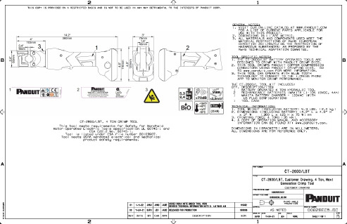
11-24-21
CHK
JEH
SCALE
NONE
DRAWING NUMBER
00828ECB_DC
SIZE
SHEET 1 OF 1
Байду номын сангаас
B
2
1
00 11-24-21 BJPU JEH JADE RELEASED FOR PRODUCTION
REV DATE BY CHK APR
DESCRIPTION
115032 093806
ECN
THIRD ANGLE PROJECTION
MATERIAL
AS NOTED
DRAWN BY DATE
BJPU
TOOL SPECIFIC NOTES:
1. THE CT-2600/LBT BATTERY OPERATED TOOLS ARE
B
DESIGNED TO CRIMP WITH PANDUIT CRIMP DIES.
2. THIS TOOL CRIMPS PANDUIT COPPER COMPRESSION
- 1、下载文档前请自行甄别文档内容的完整性,平台不提供额外的编辑、内容补充、找答案等附加服务。
- 2、"仅部分预览"的文档,不可在线预览部分如存在完整性等问题,可反馈申请退款(可完整预览的文档不适用该条件!)。
- 3、如文档侵犯您的权益,请联系客服反馈,我们会尽快为您处理(人工客服工作时间:9:00-18:30)。
MP Tool Release NoteRelease NoteMP Tool IntroductionDate: 2017/07/07Version: 2.5CHANGE HISTORY©2013 Realtek Semiconductor Corp.2©2013 Realtek Semiconductor Corp.3©2013 Realtek Semiconductor Corp.4Table of ContentsI. INTRODUCTION ............................................................... 5 II. MP STRUCTURE .............................................................. 5 III. MP TOOL USER INTERFACE ................................................... 7 IV. MP TOOL OPERATION ........................................................ 29 V. MP COMMANDS ............................................................... 31 VI. HOW TO PORTING AUTO TEST PROGRAM FROM MP TOOL ............................. 46 VII. CALCULATE TX POWER INDEX OF NORMAL DRIVER ................................ 50 VIII. TX POWER TRACKING TABLES ............................................... 79 IX. TX POWER INDEX FOR AC-SERIES CHIPS –8812AR/BR, 8881A, 8814, AND 8194 ....... 87 X. RELEASE HISTORY .. (98)©2013 Realtek Semiconductor Corp.5I. IntroductionThis document will introduce the basic concept of whole MP structure, the meaning of items appeared in UI of MP Tool, and how to operate this tool to execute RF verifications.II. MP StructureThere are three elements to compose a basic MP structure● PC (with MP tool UI)● DUT (Realtek WiFi device with daemon ‘UDPServer’ launched) ● Ethernet Cable (for communication between PC & DUT)Run UI: MP Tool Run daemon: UDPServerFigure 1. basic MP structure©2013 Realtek Semiconductor Corp.6The procedure of running MP is like this:1. User control UI of MP tool.2. MP Tool send MP commands (according to UI operation) to DUT in form of UPD packets3. DUT receive & parse these UPD packets by daemon – UDPServer4. UDPServer execute these MP commands in system.5. MP operations can be performed by these MP commands. (like switch channels, select Tx powers, send packets…)(PC Side)(DUT Side)Figure 2. example of MP flow©2013 Realtek Semiconductor Corp.7III. MP TOOL User InterfaceThis chapter will introduce the items appeared in UI of MP Tool.1. General Page:This Page is for user to launch mp operation, change WiFi setting and do RF verifications (like Tx, Rx, Power Tracking…)Figure 3. Layout of General page©2013 Realtek Semiconductor Corp.81.1 Items of General Page:1. Release version & dateIn the top-left of this page, there is information about the tool version & release date.2. EFUSE TYPEIt’s for WiFi DUT’s hardware setting (int/ext pa, trswitch…), select one of these four types or input values manually. MP Tool will input values of this item into values of WiFi mibs <trsw_pape_C9> & <trsw_pape_CC> in DUT.Note:This item only need to be set in 92D.3. IP AddressIP address of DUT (for generation of UDP session)©2013 Realtek Semiconductor Corp.94. Test Log<Test Log>Check <Test Log> before clicking <Open>, and all the MP tool commands that are send to DUT MP daemon will be recorded in a text file named “test_log_year_month_date_hour_minute_second.txt” under folder “MP_TEST_LOG \” such as “MP_TEST_LOG \test_log_2015_03_09_16h20m3s.txt”.5. IC TYPESelect the correct WiFi chip for DUT.76. MacPhyModeThe mapping of <IC TYPE> & <MacPhyMode> shall be selected as below table.Note:Just select the correct IC TYPE, no need to change MacPhyMode.7.DevSelect WLAN interfaces.8.Phy BandSelect phy band for selected WLAN interfaces.Note:Below table are supported selections, out of these selections may encounter problems.Note:PhyBand is decided automatically by device except 92D SingleMac mode.9.RFE Type (Only for 8812BR, 8197F, 8814 and 8194)When “Open” is clicked, MP tool will check the RFE type by reading MIB rfe_type and fill it in <RFE Type> automatically. There is no need to manually select this combo-box unless one would like to do some experiments by using different RFE types.The following table shows the RFE types with related FEM:©2013 Realtek Semiconductor Corp.10Release Note©2013 Realtek Semiconductor Corp.11Note.It is only for 8812BR, 8197F, 8814 and 8194A.10. PA Type (8812AR and 8881A only)Different external PA type need different baseband setting.When this item is select, it will cause wlan interface restart.Note.It is for 8812AR and 8881A only.11. Channel©2013 Realtek Semiconductor Corp.12If < PhyBand > = 5G, channel supports from 36 to 177. If < PhyBand > = 2.4G, channel supports from 1 to 14.12. TX PowerSelect expected Tx Power Index for antanna A/B/C/D, range from 0 to 63,Selected value of Tx Power Index +1, real Tx Power +0.5 dBm (approximately).13. AntennaSelect Antenna PATH for MP Tx/Rx Test.14. DataRateSelect expected data rate for MP Tx Test.15. Packet Count & Length©2013 Realtek Semiconductor Corp.13<Packet Count>: enter value of number of Tx Packet user want to transmit. <Packet Length>: enter value of length of each Tx Packet.16. BandWidthSelect the bandwidth between 20MHz / 40MHz or 80MHz17. GISelect Short or Long GI.18. XCAPSelect the expected crystal cap value (0~63).19. TR SwitchPlease select this item if DUT needs support of TR Switch. Note.It is for 88R, 92C, and 92D only.20. Test Setting©2013 Realtek Semiconductor Corp.14< Test Item >Select test items for MP Tx/Rx verifications,Packets TX: Packet TX TestIn this function, we could set Channel, TX power, Antenna, DataRate, TX packet count. If you check infinitely Packet TX, the test does not stop until pushing stop button.Packets RX: Packet RX TestOnly two parameters, Channel and Antenna, were used in the function.Continuous TX SingleTone: Single Tone TX Test (only on CCK mode) In this function, we could set Channel , TX power , Antenna , and DataRate . But DataRate Parameters should be: 1, 2, 5.5 or11.Continuous TX:In this function, we could set Channel , TX power , Antenna , and DataRate .Carrier Suppression TX: Continuous TX Test Carrier Suppression (only on CCK mode) In this function, we could set Channel , TX power , Antenna , and DataRate . But DataRate Parameters should be: 1, 2, 5.5 or 11.< infinitely for Packet TX>If selected & Start MP Tx Test, DUT will Tx Packets until user stop test manually. (If not selected, DUT will only Tx numbers of packets from <Packet Count>)< Silent Mode >In this mode, it will not show the Tx/Rx packet so that the console will not print statistics message.< Hardware Tx >This is for 8197F, 8812BR, 8814 and 8194 only. If “Packets Tx” starts with this checkbox checked, the DUT will transmits packets by directly setting hardware registers rather than generating software packets from higher level. In this way, the data will not be transfferd through DMA, and thus the packet period can be precisely fixed, and the packet length can extend to 60,000 Bytes. (8197F, 8812BR, 8814 and 8194 only).< Start / Stop test >©2013 Realtek Semiconductor Corp.15After select expected WiFi setting & test items listed above, press these 2 buttons to start & stop MP verifications.Note:Above items shall be configured correctly before starting MP Test.21. StatisticsIf doing Packets TX or Packets RX , the statistics will be displayed in below TextBox.< Reset >It will clear all Tx/Rx counter.22. Initial Gain Value< Read >Read initial gain values for all paths by pressing23. Power Tracking©2013 Realtek Semiconductor Corp.16<PG thermal>Enter the expected Thermal value to here.<Read>Push this button to get the current thermal value and it will show on the “Current thermal” textbox.Push button <Power Tracking ON> & <Power Tracking OFF> to start/stop Tx Power TrackingEnable function of Power Tracking (Add additional Tx Power from Gain Tables) Read the current Thermal value from DUT. 24. Register Read/WriteRead or write baseband or RF registers.<BB/RF>Select register set- BB or RF.<RF Path> Select RF path.<Offset>Fill in the desired register offset<Value>The read/ written register value is shown here.<Read>Press this button to read register<Write>©2013 Realtek Semiconductor Corp.17Press this button to write to register25. Continuous Monitor<Enable Monitor>Enabling continuous read to specific register26. HW Tx Configuration (8197F, 8812BR, 8814 and 8194 only)This section is used only when < Hardware Tx > is checked. There are some configurable items listed as blow:<STBC>Enable STBC Tx packets<LDPC>Enable LDPC Tx packets<Period>Tx packet period<Pattern>Tx packet patternNote.It is for 8197F, 8812BR, 8814 and 8194A only.27. Power By Rate©2013 Realtek Semiconductor Corp.18<Get_From_Flash>It will read flash calibrated data and show it on the textbox. (11M, 54M, HT-MCS7, HT-MCS15, HT-MCS23, HT-MCS31, VHT 1S MCS7, VHT 2S MCS7, VHT 3S MCS7, and VHT 4S MCS7)<Load_PG_File>It will read the .txt file in the MP_TOOL folder.The following files should be in the folder: PHY_REG_PG_88E_new.txt PHY_REG_PG_92C.txt PHY_REG_PG_92D.txtPHY_REG_PG_92E_new.txt PHY_REG_PG_8812_new.txt PHY_REG_PG_8881Am.txt PHY_REG_PG_8814Amp_hp.txt PHY_REG_PG_8197Fmp.txt PHY_REG_PG_8822Bmp.txtNote.The file name should not be changed or it will lead to read file failure.<Update>Update the result to the “Power Index” items according to the selected data rate, bandwidth, and channel.<Path>Select the desired path to show the power by rate values and calibrated flash data.Note.The Tx power index of VHT-MCS8, VHT-MCS9 will be “index of VHT-MCS7” minus power by rate index of VHT-MCS8 / VHT-MCS9<Reset>Reset all power by rate data.28.Tx Power Limit<Load Table>It will read the .txt file in the MP_TOOL folder.The following 6 files should be in the folder:TXPWR_LMT_88E_new.txtTXPWR_LMT_92c.txtTXPWR_LMT_92d.txtTXPWR_LMT_92EE_new.txtTXPWR_LMT_8812_new.txtTXPWR_LMT_8881A_new.txtTXPWR_LMT_8814Amp.txtTXPWR_LMT_8197Fmp.txtTXPWR_LMT_8822Bmp.txt<Antenna Path>Select the tested antenna.<TxPowerLimit index>Select the tx power limit index to decide which column in limit table to use. If “0” is selected,<Region domain> will decide which colum to use.When items above are all decided, <Limit Power> displays the limited power in dBm for each rate. <Target Power> displays the target power in dBm for each rate based on the highest rates in the choosen powe-by-rate table.©2013 Realtek Semiconductor Corp.19©2013 Realtek Semiconductor Corp.20The “Power Index” will be updated when “Data Rate” is selected and the value will be limited according to <Limit Power> and <Target Power>.2. Flash Page –for 92C, 92D, 88E, 92Eand 97F:This Page is for user to read/write calibration values from/into Flash or Efuse of DUT. Like Tx Power Indices for all groups of channels, Thermal value & crystal values…etc.©2013 Realtek Semiconductor Corp.21Figure 4. Layout of Flash Page2-1. Items of Flash Page:1. Wlan port.Wlan port indicates the flash page of which wlan device. E.g. wlan0 / wlan1.2. Tx Power Indices for all groups of channels.Tx Power Index (TPI) is the value to control the level of Tx Power, the bigger the value of TPI. The stronger the level of Tx packets.TPI +1 = Tx Power Level + 0.5dBm . (approximately)In general, the target Tx power is about 13 dBm, so we can utilize these flash items to store the target TPI (to reach power level of 13dBm) for normal driver.©2013 Realtek Semiconductor Corp.22Figure 5. Group division of channels in Flash pageIn this MP Tool, we split available 2.4GHz channels into 3 groups, channels in the same group share the same TPIs for both antenna A & B.In this MP Tool, we split available 5GHz channels into 9 groups, channels in the same group share the same TPIs for both antenna A & BTable 4. 5G channel groups.Note.The group division of channels in flash page is adapted to the following chips : RTL8192C ,RTL8192D ,RTL8188E ,RTL8192E ,RTL8197FWe use the following items to store TPI for all rates (CCK, OFDM, MCS-1T, MCS-2T)<CCK>Refers to power of CCK rates (for 2.4G only)<HT-1S>Refers to power of the first of wireless special stream<Diff-HT-2S>Refers to the difference between the first and the second of wireless special stream<Diff-OFDM>©2013 Realtek Semiconductor Corp.23Refers to the difference between OFDM and HT-1S.<Diff-HT20>Refers to the difference between 20M and 40MPS:The MAX value of TPI for all rates is 63(in decimal).3. Buttons to Read/Write Tx Power Indices for all groups of channels. In this MP TOOL, it will recognize the chip version and the phy band automatically.<2.4G support>This button is only available in RTL8192D since it supports both 2G and 5G.<13dBm/6dBm>This button is only available in RTL8192D. You can press the TextBox show XXdBm to switch.After these 2 items selected done, user can press <Read> <Write> buttons in Flash group to perform R/W function of Tx power items from DUT’s flas h.Flash - <Read> : Read Tx Power items from flash of DUT, and displayed in UI. Flash - <Write> : Write Tx Power items displayed in UI into flash of DUTIn Efuse group, there are 3 buttonsEfuse - <Read> : Read Tx Power items from Efuse, and displayed in UI. Efuse - <Write> : Write Tx Power items displayed in UI into Efuse-Map of DUT. Efuse - <Sync> : Write modified Efuse-Map into Efuse of DUT.Example: after user made MP verification made by operation of General page, user knows in channel 9, use CCK rate, set Tx Power = 29 can reach his expected Tx power level (like 13dBm), then user can input value 29 into TextBox of CCK-Group1-MID manually, then do Flash-<Write>. Then, normal driver will know to use TPI=29 for CCK rates for channel 9.PS:Because Efuse has its limits of times of writing, so we store the expected writing value in©2013 Realtek Semiconductor Corp.24/proc/mib/wlanXX/mib_rf (so called Efuse-Map) After executing Efuse-Write, Efuse-Map will be modified.After executing Efuse-Sync, WiFi dirver will do real Efuse writing from the modified parts of Efuse-Map.4. MAC / REG_DOMAIN / XCAP / THER / TRSW_PAPE SettingPress the button Flash-Read/Write to read/write these values from flash. 4.1 TRSWPAPE_C9_CCThis setting is only for RTL8192D to configure hw setting.4.2 XCAPPress <Read> <Write> buttons to Read/Write these values from flash of DUT.Only RTL8192D needs to fill “Crystal Capacitor In ” and “Crystal Capacitor Out ”. Other chips only need to fill “Crystal Capacitor In ”.5. Efuse for 88E and 92E©2013 Realtek Semiconductor Corp.25This efuse page only supports 88e and 92e. For CCK power, channels are divided into 6 groups as shown, while channels are divided into 5 groups for HT40 power:Button <Read> : Read data from efuse and fill them in the blanks. Button <Write > : Write the data in the blank to driver’s efuse -map. Button <Sync > : Write driver’s efuse -map to DUT’s efuse device.©2013 Realtek Semiconductor Corp.263. Flash_AC Page –for 8881A, 8812AR/BR, 8814, and 8194:1. Select interface, band, and antenna combination before calibrationSelect interface:Select band:©2013 Realtek Semiconductor Corp.27Select antenna combination:2. Tx Power Indices for all groups of channels.We divide 5GHz channels into 14 groups in RTL8812AR/RTL8812BR/RTL8881A/RTL8814, and use the following items to store TPI for all rates.<HT40-1S>Refers to power of the first of wireless special stream in 40MHz mode<Diff-OFDM>Refers to the difference between OFDM and HT40-1S<DIFF-HT20-1S>Refers to the difference between 20MHz and 40MHz of one special stream<DIFF-HT20-2S>Refers to the difference between 20MHz one special stream and two special streams<DIFF-HT20-3S>Refers to the difference between 20MHz two special stream and three special streams<DIFF-HT40-2S>Refers to the difference between 40MHz one special stream and two special streams<DIFF-HT40-3S>Refers to the difference between 40MHz two special stream and three special streams<DIFF-HT80-1S>Refers to the difference between 80MHz and 40MHz of one special stream<DIFF-HT80-2S>Refers to the difference between 80MHz one special stream and two special streams<DIFF-HT80-3S>Refers to the difference between 80MHz two special stream and three special streams <Reset>Press reset button will clear all changes in MP TOOL.If you want to set the same difference value in all channels, you can do as the follow figure :©2013 Realtek Semiconductor Corp.283. PA typeThis should only be set when RTL8812AR use different external pa.The mapping of pa type and flash entry is :Skywoks-5022 – flash set HW_WLAN0_PA_TYPE 0RFDM-4501 / Skyworks-85793 –flash set HW_WLAN0_PA_TYPE 1 Skywoks-5023 – flash set HW_WLAN0_PA_TYPE 2 RTC-5634 – flash set HW_WLAN0_PA_TYPE 3©2013 Realtek Semiconductor Corp.29IV. MP Tool OperationThis chapter will introduce how to operate MP Tool. Before going through these steps, the MP nfjrom has to be loaded to the DUT:Step 0. Loading MP nfjrom to DUTFirst plug in the DUT and press ESC when booting to enter console mode of bootloader. Then use Windows CMD command line to execute tftp to transfer MP nfjrom to the DUT. The default IP address of bootloader is 192.168.1.6, so the command looks like this:tftp –i 192.168.1.6 put “C:\patch\nfjrom”Step 1. Open MP session- select correct <EFUSE TYPE> or input C9&CC value manually for DUT (Only RTL8192D needs this step)- input the correct <IP Address> of DUT- select your <IC TYPE> (just follow default setting like below pictures) - press <Open> buttion.Figure 6.default setting of 8192C for open MP sessionStep 2. Config WLAN settingIf open MP session successfully, it will show the chip name on the UI and all RF items can be selected (or input value) now.Then users can try to config WiFi setting as their wish, but please follow this table for listed items.PhyBand and MAC/PHY Mode will be auto selected after open except the IC TYPE is RTL8192D .©2013 Realtek Semiconductor Corp.302. Select Test Items and Start MP Verification.After WiFi setting done, user can select <Test Item> want to execute, and then press <Start> to start test, press <Stop> to stop test.3. Use Flash Page/Flash_AC Page to save calibration data.From test results, user may now know which specific Tx power index is suitable for specific data rate for some channels, so, user can use Flash page to store these calibration data.4. End MP SessionJust press <Close> button in General Page.V. MP CommandsAs mentioned before, MP operation is formed by executing MP commands, any of user’s actions to UI of MP tool were all converted into sets of MP commands, this chapter will introduce the basic MP commands(format, usage, examples…), then user can try to type these commands by conso le interface, in order to do MP operations without MP Tool program installed in PC.1.IntroductionRealtek WiFi Linux driver supports driver based Mass Production functions. Customers can utilize these functions to do EMI test and other simple TX and RX test. Under Realtek WiFi turnkey, we use Linux utility “iwpriv” to get and set I/O control to WLAN driver. The following commands are executed under Linux command prompt. The MP functions will only operate after the WLAN interface is opened.age1.Start MP mode:packets. All connection with other stations will be broken. Beacon transmitting is also stopped. If the original state is client mode, the roaming will be stopped.2.Stop MP mode:other commands. It will not return to normal operation mode. System should close the WLAN interface and open again to get WLAN work normally.©2013 Realtek Semiconductor Corp.31©2013 Realtek Semiconductor Corp.323. Set Tx rate:value sets the rate of Tx packets.For example, set Tx rate to MCS 7: iwpriv wlan0 mp_rate 135Note.Since 8814 and 8194 support 3 spatial stream, the values for HT rate extends to 151, and the base value for VHT is 160 rather than legacy 144.For 8814 and 8194, the value is as following:E.g. set Tx rate to VHT NSS1 MCS 7: iwpriv wlan0 mp_rate 167©2013 Realtek Semiconductor Corp.334. Set operational channel:Set the operational channel of transmitting and receiving packets.E.g. set channel to 6:iwpriv wlan0 mp_channel 65. Set operational bandwidth:sgi sets guard interval of transmitting MCS packet, 1 for short GI, 0 for long GI Set the operational bandwidth for transmitting and receiving packets. Set the guard interval fortransmitting MCS packets. If the parameters are not given, the default action is set bandwidth to 20M mode and long GI to transmitting packets.For example, set bandwidth to 40M, and no shortGI: iwpriv wlan0 mp_bandwidth 40M=1,shortGI=06. Set Tx power:b sets Tx power level for path Bc sets Tx power level for path Cd sets Tx power level for path DSet the transmitting power level of path A, B, C, and D. If the DUT only has one path, just specify patha.For example, set path A power index to 20, and path B to 30: iwpriv wlan0 mp_txpower patha=20,pathb=307. Set xcap value:Set the PHY related parameters of crystal capacitor.For example, set crystal capacitor to 31: iwpriv wlan0 mp_phypara xcap=31©2013 Realtek Semiconductor Corp.348. Set antenna for Tx:for antenna D, ab for antenna A and B, abc for antenna A, B, and C, and abcd for antenna A, B, C, and DSet the operational antenna for Tx on the target board.For example, set Tx operational antenna to path A: iwpriv wlan0 mp_ant_tx a9.Set antenna for Rx:ant sets the operational antenna for Rx, a for antenna A, b for antenna B, c for antenna C, d for antenna D, ab for antenna A and B, abc for antenna A, B, and C, and abcd for antenna A, B, C, and DSet the operational antenna for Rx on the target board.For example, set Rx operational antenna to path A: iwpriv wlan0 mp_ant_rx a10. Start air Rx mode:start clears counters and start to accumulate Rx packets stop stops counts and show the statisticsThis command is for air receiving test. Use start command to clear all the counters and start toaccumulate the received packets. Use stop command to stop counting and show the statistics of correct packets and CRC-error packets.11. Start continuous Tx mode:n sets the number of packets to send background sends packets in background mode stop stops the background sending pkt sends packet tx, i.e., not sent by hardware cs sends carrier suppression stone sends single toneThis command is for continuous transmitting test. Use time command to assign the time to send packets. Use count command to assign the number of packets to send. If both of time and count are not specified,©2013 Realtek Semiconductor Corp.35the sending function will continue infinitely. It can be stopped when any key is pressed (should be specifically implemented in other platform) while background command is not specified. If cs isspecified, the sending signal will be a carrier suppression signal. Use stone command to send single tone signal for frequency testing. If stone is specified, the sending signal will be single tone and not adistinguishable packet any more. Use background command to tell driver to send packets in background. The command line control will return and packet sending is continuous. It can be stopped by stopcommand. By default, packets will be sent by hardware for shorter duty cycle. If pkt is specified, packets will be sent by software.For example, start background packets Tx infinitely: iwpriv wlan0 mp_ctx background,pkt12.Query air tx/rx statistics: This command is for packet counting. Under packet transmitting, use this command to get the number of packets being transmitted. Under receiving, use this command to get the statistics of correct packets and CRC-error packets.13. Set Band ModeSet the operational band mode on the target board. This is set only for RTL8192D.14. Start air Rx mode: off stops mp dig.This command is only for RTL8812AR/BR and RTL8814 while receiving test. Use on command to start mp dig and it will change the initial gain setting depends on false alarm counter. Use off command to stop mp dig and it will set initial gain to default.15. Start power tracking:stop stop power trackingStart power tracking and set the tracked thermal as xFor example, start power tracking and set the tracked thermal as 32: iwpriv wlan0 mp_pwrtrk ther=32©2013 Realtek Semiconductor Corp.3616. Start hardware Tx (8197F, 8812BR, 8814 and 8194 only):Start to transmit hardware TX packets. The packet type is described in the argument set, including Tx rate, packet period, MAC address, .etc.The argument set contains 56 arguments, which are listed in order as below:{Ntx:4, Mode:3, bEnPMacTx:1}, TX_RATE, TX_RATE_HEX, TX_SC, {BandWidth:3, NDP_sound:1, bLDPC:1, bSTBC:1, bSPreamble:1, bSGI:1}, m_STBC, PacketPeriod, PacketCount, PacketLength, PacketPattern, SFD, SignalField, ServiceField, LENGTH, CRC16[0], CRC16[1], LSIG[0], LSIG[1], LSIG[2], HT_SIG[0],HT_SIG[1],HT_SIG[2],HT_SIG[3],HT_SIG[4],HT_SIG[5], VHT_SIG_A[0], VHT_SIG_A[1],VHT_SIG_A[2],VHT_SIG_A[3],VHT_SIG_A[4],VHT_SIG_A[5], VHT_SIG_B[0],VHT_SIG_B[1],VHT_SIG_B[2],VHT_SIG_B[3], VHT_SIG_B_CRC,VHT_Delimiter[0], VHT_Delimiter[1], VHT_Delimiter[2], VHT_Delimiter[3], MacAddress[0], MacAddress[1], MacAddress[2], MacAddress[3], MacAddress[4], MacAddress[5]Since the calculation of arguments LSIG , HT_SIG , VHT_SIG_A, .etc involves floating point operation, these arguments are calculated by MP tool. Please refer to MP tool and MP API to generate the arguments and issue this command.For example, start to transmit 40M, channel 38, MCS7 packets infinitely: iwpriv wlan0 mp_pmac_ctx17,-121,19,0,32,1,0,100,0,0,0,0,0,0,3,-24,0,0,0,0,0,0,0,0,0,0,-53,6,2,-121,-24,3,7,84,0,0,0,0,0,0,0,0,0,0,0,0,0,0,0,0,-1,-1,-1,-1,-1,-13. ExamplesThe standard procedure is, firstconfig WiFi mibs to determine types of Band(5G/2.4G), Mode(A/B/G/N) and PA(extPA/intPA) then open WiFi driver and enter MP mode. then use mp commands to dynamically set channel, rate, antenna, power level… then use mp commands to perform Tx/Rx verifications and query statistics. after done testing exit MP mode and re-open WiFi driver.The following introduces the command lists for some examples.1. Init and Open WiFi Driverifconfig wlan0 down(iwpriv wlan0 set_mib trsw_pape_C9=0)// 92D only,。
