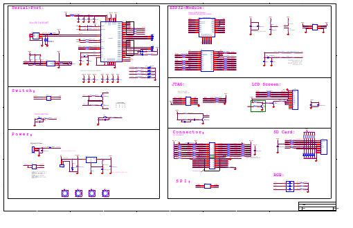
ESP-WROVER-KITJ-v1 开发板原理图
乐鑫ESP-WROVER-KIT开发板原理图
PWREN# SUSPEND#
10
1 5 11 15 25 35 47 51
R37/0R :ON 32K-CLK:R36/0R、 R38/0R、 R39/0R :OFF
GPIO:R36/0R、 R37/0R :OFF R38/0R、 R39/0R :ON
GND FT_GPIO3 GND FT_GPIO2 FT_GPIO1 VDD1V8 VDD1V8 VDD1V8 VDD33 VDD33 VDD33 VDD33 FT_GPIO0 C15 C16 C17 C18 C19 C20 C21 GND R40 R41 R42 2K(1%) 2K(1%) 2K(1%) D10 1 D11 1 D12 1 RED LED 2 RED LED 2 RED LED 2 R39 2K(1%) D9 1 RED LED 2
7 8
DM DP FT2232HL
D3 D4 GND VDD33 R4 R5 12K(1%) REF 1K(1%) RESET# 6 14 REF RESET#
FT_GPIO0 FT_GPIO1 FT_GPIO2 FT_GPIO3 TXD RXD nRTS nCTS nDTR nDSR nDCD nRI TXDEN 2 nRXLED nTXLED nPWRSAV nPWREN nSUSPEND D6 D5 2 BLUE LED 1 R9 RED LED 1 R15
Please place near IC-Pins.
VDD33
VDD33
VDD33 R2
Micro USB 5V&USB-UART
GND
GND C5 C8
GND 4.7uF/25V 4.7uF/25V
GND VDD33 50 VDD1V8 49 VREGIN
MSEK实验套件原理图

2
Title
D
Size
Number
Revision
A4
Date: File:
2013/12/16
Sheet of
E:\AllWork\..\Freq_Phase_Lock_Tiva.SCHDDrOawCn By:
3
4
1
2
VCC
C4
C7
R2
A
0.1uF 10uF 10v
47K S0
TP1
ADC
GND R1 10k
U4B
102
R7
R8
5 GND
7 LMV842
IOUTB
+5V C13 30pF2
8
AMP_OUTB
C12 104
GND
AMP_OUTB
U4A 1
3 AMP_OUTA 2 1 AMP_OUTB
C142k 104
J2
R9
+5V 22k
2.4k
6
U2B
7
5
TLV2372
R10 ADC Driver 10k
NC NC
-IN +V
+IN OUT
-V
NC
8 7 6 5
OPA330
VCC C11 1uF
GND 电压测量电路
C
VCC
J1
+3.3V PB5 PB0 PB1 PE4 PE5 PB4 PA5 PA6 PA7
J3
VBUS GND PD0 PD1 PD2 PD3 PE1 PE2 PE3 PF1
V5+ GND
VCC
GND
C13 0.1uF
TIME2 4
ESP-WROVER模组治具制作规范说明书

机台型号
ESP-WROOM-02
ESP-WROOM-02D
ESP-WROOM-02/02D-V1
ESP-WROOM-02DC
ESP-WROOM-02U
ESP-WROOM-02UC
Espressif
ESP-WROOM-02U-V3*
! /18
5
2019.01
2. 模组治具的主要结构
!
模组类型
V1.1
更更新表 2-1,增加新模组信息。
文文档变更更通知
用用户可通过乐鑫官网网订阅⻚页面面 https:///zh-hans/subscribe 订阅技术文文
档变更更的电子子邮件通知。
证书下载
用用户可通过乐鑫官网网证书下载⻚页面面 https:///zh-hans/certificates 下载产
Espressif
! /18
4
2019.01
2. 模组治具的主要结构
!
此串串口口板包括两颗串串口口芯片片,其在底箱的放置方方式如图 2-5 所示。根据夹具的类型放置对
应数目目的串串口口板(如“一一拖四”治具则需要放置 4 块串串口口板)。
!
图 2-6. 底板放置示意图
要求底板须固定在底箱里里里,防止止串串口口板位置不不固定导致管脚触碰短路路现象。固定时采用用螺
!
图 2-4. 活动台与模组台之间的距离示意
2.2. 底箱制作规范
2.2.1. 串串口口板
底箱内放有串串口口板,使用用的串串口口板的版本号为:ESP_Factory Test Board V1.3,如图 2-5
所示:
!
图 2-5. 串串口口板示意 (ESP_Factory Test Board V1.3)
ESP32-WROVER 模组技术规格说明书
不推荐用于新设计(N R N D )ESP32WROVER技术规格书版本2.7乐鑫信息科技版权©2023关于本文档本文档为用户提供ESP32-WROVER模组的技术规格。
文档版本请至乐鑫官网https:///zh-hans/support/download/documents下载最新版本文档。
修订历史请至文档最后页查看修订历史。
文档变更通知用户可以通过乐鑫官网订阅页面/zh-hans/subscribe订阅技术文档变更的电子邮件通知。
您需要更新订阅以接收有关新产品的文档通知。
证书下载用户可以通过乐鑫官网证书下载页面/zh-hans/certificates下载产品证书。
1概述62管脚定义8 2.1管脚布局8 2.2管脚描述9 2.3Strapping管脚103功能描述12 3.1CPU和内存12 3.2外部Flash和SRAM12 3.3晶振12 3.4RTC和低功耗管理124外设接口和传感器135电气特性14 5.1绝对最大额定值14 5.2建议工作条件14 5.3直流电气特性(3.3V,25°C)14 5.4Wi-Fi射频15 5.5低功耗蓝牙射频165.5.1接收器165.5.2发射器166电路原理图177外围原理图188模组尺寸199PCB封装图形2010外部天线连接器尺寸2111产品处理22 11.1存储条件22 11.2静电放电(ESD)22 11.3回流焊温度曲线22 11.4超声波振动2312相关文档和资源24修订历史251ESP32-WROVER订购信息6 2ESP32-WROVER产品规格6 3管脚定义9 4Strapping管脚10 5Strapping管脚的建立时间和保持时间的参数说明11 6绝对最大额定值14 7建议工作条件14 8直流电气特性(3.3V,25°C)14 9Wi-Fi射频特性15 10低功耗蓝牙接收器特性16 11低功耗蓝牙发射器特性161ESP32-WROVER管脚布局(顶视图)8 2Strapping管脚的建立时间和保持时间11 3ESP32-WROVER电路原理图17 4ESP32-WROVER外围原理图18 5ESP32-WROVER尺寸图19 6ESP32-WROVER封装图形20 7外部天线连接器尺寸图21 8回流焊温度曲线221概述ESP32-WROVER 是通用型Wi-Fi +Bluetooth +Bluetooth LE MCU 模组,功能强大,用途广泛,可以用于低功耗传感器网络和要求极高的任务,例如语音编码、音频流和MP3解码等。
开发板原理理图

单⽚片机外围⽤用户接⼝口标准IO开发板引出⼏几路路通⽤用IO,有Reset复位按键;⽤用户LED两路路蓝⾊色;⽤用户按键两路路,作为输⼊入使⽤用;蜂鸣器器作为提醒⽤用户使⽤用;1套Arduino标准接⼝口;1套通讯模组扩展⼝口,8P*6P;4路路电源开关:单⽚片机⼀一路路,WiFi模组⼀一路路,SUB1G 模组⼀一路路,通讯模组⼀一路路。
单独可以控制开关,单独可以关闭电源指示灯;USB 转串串⼝口多路路调试,UART4,UART5,USART3,USART1;USART1,⽤用于NB通讯模组;USART3,⽤用于WiFi模组;USART2,⽤用于Arduino扩展;通讯模组NB-IoT模组由锂电池直接供电;BC95 NB-IoT模组使⽤用USART2与单⽚片机通讯;有⼀一个总电源插座B C95 PWR;Sub-1GnRF24L01是直插式,天线朝向开发板外部插⼊入;PCB 布局整体布局本开发板整体布局较为紧凑,按理理说开发板应该做的宽松和相对密度⼩小⼀一些,⽽而本开发板在布局上参考了了实际项⽬目中的产品设计布局⽽而特意做成⾼高密度型,这样便便于读者参考,应⽤用在实际项⽬目中以减少PCB⾯面积。
本开发板是双层PCB板,元器器件⼤大部分是在表⾯面布局,读者在实际产品应⽤用过程中可以做成双⾯面焊接以节省PCB⼤大⼩小。
模组和其他外设可以摆放背⾯面,既美观⼜又节约空间;观⼜又节约空间;开发板采⽤用了了0805封装的电阻电容焊盘,⼀一⽅方⾯面是⽅方便便查看元器器件的型号,另⼀一⽅方⾯面是便便于维修和看清整体布局。
读者在实际应⽤用过程中,可以替换成0603或0402更更⼩小⼀一些的封装;为了了⽅方便便安装和替换锂电池,本开发板使⽤用了了XH2.54焊盘,采⽤用扁平的锂电池节省PCB空间,减少产品的物理理⾼高度;本开发板NB模组射频采⽤用板载PCB式天线,读者可以参考此天线设计做在实际产品中,⼀一⽅方⾯面是减少安装外置天线的步骤,另⼀一⽅方⾯面是没有外置天线占⽤用物理理空间。
开发板电路原理图
VCC WE A1 3 A8 A9 A1 1 OE A1 0 CE D7 D6 D5 D4 D3
28
27
26
A1 3
25
A8
24
A9
23
A1 1
2 2 PSEN
21
A1 0
20
19
D7
18
D6
17
D5
16
D4
15
D3
VCC C4 0 .1 u F
AT28 C2 56
扩展外部数据存储器和仿真存储器,地址为8000-- - -- FFF FH
VCC ILE
WR2 XF ER
D4 D5 D6 D7 Io u t2 Io u t1
20
VCC
19 1 8 DAC_W R
1 7 DAC_CS 1 6 DAC_D4
1 5 DAC_D5 1 4 DAC_D6
1 3 DAC_D7
12
11
+12 V GND -1 2 V
J 10 1
1 2 3
CON3
1
1
2
3
4
5
6
7
8
9
10
11
12
13
14
15
16
17
18
19
20
HEADER 1 0 X2
DAC _C S DAC_W R DAC _D0 DAC _D1 DAC _D2 DAC _D3 DAC _D4 DAC _D5 DAC _D6 DAC _D7
U9 DAC08 3 2
CS WR1 AGND D3 D2 D1 D0 Vref R fb DGND
J P9 HEADER 8 X2
ESP32-S2-WROVER 和 ESP32-S2-WROVER-I 产品手册说明书
ESP32-S2-WROVER&ESP32-S2-WROVER-I DatasheetVersion1.0Espressif SystemsCopyright©2020About This DocumentThis document provides the specifications for the ESP32-S2-WROVER and ESP32-S2-WROVER-I module.Document UpdatesPlease always refer to the latest version on https:///en/support/download/documents.Revision HistoryFor revision history of this document,please refer to the last page.Documentation Change NotificationEspressif provides email notifications to keep customers updated on changes to technical documentation.Please subscribe at /en/subscribe.CertificationDownload certificates for Espressif products from /en/certificates.Disclaimer and Copyright NoticeInformation in this document,including URL references,is subject to change without notice.THIS DOCUMENT IS PROVIDED AS IS WITH NO WARRANTIES WHATSOEVER,INCLUDING ANY WARRANTY OF MERCHANTABIL-ITY,NON-INFRINGEMENT,FITNESS FOR ANY PARTICULAR PURPOSE,OR ANY WARRANTY OTHERWISE ARISING OUT OF ANY PROPOSAL,SPECIFICATION OR SAMPLE.All liability,including liability for infringement of any proprietary rights,relating to use of information in this docu-ment is disclaimed.No licenses express or implied,by estoppel or otherwise,to any intellectual property rights are granted herein.The Wi-Fi Alliance Member logo is a trademark of the Wi-Fi Alliance.The Bluetooth logo is a registered trademark of Bluetooth SIG.All trade names,trademarks and registered trademarks mentioned in this document are property of their respective owners,and are hereby acknowledged.Copyright©2020Espressif Systems(Shanghai)Co.,Ltd.All rights reserved.1.Module Overview 1.1FeaturesMCU•ESP32-S2embedded,Xtensa®single-core32-bitLX7microprocessor,up to240MHz•128KB ROM•320KB SRAM•16KB SRAM in RTCWi-Fi•802.11b/g/n•Bit rate:802.11n up to150Mbps•A-MPDU and A-MSDU aggregation•0.4µs guard interval support•Center frequency range of operating channel:2412~2484MHzHardware•Interfaces:GPIO,SPI,LCD,UART,I2C,I2S,Cam-era interface,IR,pulse counter,LED PWM,USB1.1OTG,ADC,DAC,touch sensor,temperaturesensor•40MHz crystal oscillator•4MB SPI flash•2MB PSRAM•Operating voltage/Power supply:3.0~3.6V•Operating temperature range:–40~85°C•Dimensions:(18×31×3.3)mmCertification•Green certification:RoHS/REACH•RF certification:FCC/CE-RED/SRRCTest•HTOL/HTSL/uHAST/TCT/ESD1.2DescriptionESP32-S2-WROVER and ESP32-S2-WROVER-I are two powerful,generic Wi-Fi MCU modules that have a rich set of peripherals.They are an ideal choice for a wide variety of application scenarios relating to Internet of Things (IoT),wearable electronics and smart home.ESP32-S2-WROVER comes with a PCB antenna,and ESP32-S2-WROVER-I with an IPEX antenna.They both feature a4MB external SPI flash and an additional2MB SPI Pseudo static RAM(PSRAM).The information in this datasheet is applicable to both modules.The ordering information of the two modules is listed as follows:Table1:Ordering InformationAt the core of this module is ESP32-S2*,an Xtensa®32-bit LX7CPU that operates at up to240MHz.The chip has a low-power co-processor that can be used instead of the CPU to save power while performing tasks that do not require much computing power,such as monitoring of peripherals.ESP32-S2integrates a rich set of peripherals,ranging from SPI,I²S,UART,I²C,LED PWM,LCD,Camera interface,ADC,DAC,touch sensor, temperature sensor,as well as up to43GPIOs.It also includes a full-speed USB1.1On-The-Go(OTG)interface to enable USBcommunication.1.3Applications•Generic Low-power IoT Sensor Hub •Generic Low-power IoT Data Loggers •Cameras for Video Streaming •Over-the-top(OTT)Devices•USB Devices•Speech Recognition•Image Recognition•Mesh Network•Home Automation•Smart Home Control Panel •Smart Building•Industrial Automation •Smart Agriculture•Audio Applications•Health Care Applications •Wi-Fi-enabled Toys •Wearable Electronics •Retail&Catering Applications •Smart POS MachinesCONTENTSContents1Module Overview3 1.1Features3 1.2Description3 1.3Applications42Block Diagram83Pin Definitions9 3.1Pin Layout9 3.2Pin Description10 3.3Strapping Pins114Electrical Characteristics13 4.1Absolute Maximum Ratings13 4.2Recommended Operating Conditions13 4.3DC Characteristics(3.3V,25°C)13 4.4Current Consumption Characteristics14 4.5Wi-Fi RF Characteristics154.5.1Wi-Fi RF Standards154.5.2Transmitter Characteristics154.5.3Receiver Characteristics155Schematics17 6Peripheral Schematics19 7Physical Dimensions and PCB Land Pattern20 7.1Physical Dimensions20 7.2Recommended PCB Land Pattern21 7.3U.FL Connector Dimensions22 8Product Handling23 8.1Storage Condition23 8.2ESD23 8.3Reflow Profile23 9MAC Addresses and eFuse24 10Learning Resources25 10.1Must-Read Documents25 10.2Must-Have Resources25 Revision History261Ordering Information3 2Pin Definitions10 3Strapping Pins11 4Absolute Maximum Ratings13 5Recommended Operating Conditions13 6DC Characteristics(3.3V,25°C)13 7Current Consumption Depending on RF Modes14 8Current Consumption Depending on Work Modes14 9Wi-Fi RF Standards15 10Transmitter Characteristics15 11Receiver Characteristics161ESP32-S2-WROVER Block Diagram8 2ESP32-S2-WROVER-I Block Diagram8 3Pin Layout(Top View)9 4ESP32-S2-WROVER Schematics17 5ESP32-S2-WROVER-I Schematics18 6Peripheral Schematics19 7Physical Dimensions20 8Recommended PCB Land Pattern21 9U.FL Connector Dimensions22 10Reflow Profile232.Block Diagram2.Block DiagramFigure1:ESP32-S2-WROVER Block DiagramFigure2:ESP32-S2-WROVER-I Block Diagram3.Pin Definitions3.1Pin LayoutFigure3:Pin Layout(Top View)3.2Pin DescriptionThe module has42pins.See pin definitions in Table2.Table2:Pin Definitions3.3Strapping PinsESP32-S2has three strapping pins:GPIO0,GPIO45,GPIO46.The pin-pin mapping between ESP32-S2and the module is as follows,which can be seen in Chapter5Schematics:•GPIO0=IO0•GPIO45=IO45•GPIO46=IO46Software can read the values of corresponding bits from register”GPIO_STRAPPING”.During the chip’s system reset(power-on-reset,RTC watchdog reset,brownout reset,analog super watchdog reset,and crystal clock glitch detection reset),the latches of the strapping pins sample the voltage level as strapping bits of”0”or”1”,and hold these bits until the chip is powered down or shut down.IO0,IO45and IO46are connected to the internal pull-up/pull-down.If they are unconnected or the connected external circuit is high-impedance,the internal weak pull-up/pull-down will determine the default input level of these strapping pins.To change the strapping bit values,users can apply the external pull-down/pull-up resistances,or use the host MCU’s GPIOs to control the voltage level of these pins when powering on ESP32-S2.After reset,the strapping pins work as normal-function pins.Refer to Table3for a detailed boot-mode configuration of the strapping pins.Table3:Strapping Pins4.Electrical Characteristics4.1Absolute Maximum RatingsTable4:Absolute Maximum Ratings4.2Recommended Operating ConditionsTable5:Recommended Operating Conditions4.3DC Characteristics(3.3V,25°C)Table6:DC Characteristics(3.3V,25°C)4.4Current Consumption CharacteristicsWith the use of advanced power-management technologies,the module can switch between different power modes.For details on different power modes,please refer to Section RTC and Low-Power Management in ESP32-S2Datasheet.Table7:Current Consumption Depending on RF ModesTable8:Current Consumption Depending on Work Modes4.5Wi-Fi RF Characteristics4.5.1Wi-Fi RF StandardsTable9:Wi-Fi RF Standards1.Device should operate in the center frequency range allocated by regional regulatory authorities.Target center frequencyrange is configurable by software.2.For the modules that use IPEX antennas,the output impedance is50Ω.For other modules without IPEX antennas,users do not need to concern about the output impedance.4.5.2Transmitter CharacteristicsTable10:Transmitter Characteristics1.Target TX power is configurable based on device or certification requirements.4.5.3Receiver CharacteristicsTable11:Receiver CharacteristicsSchematicsSubmitDocumentationFeedbackSchematics7.Physical Dimensions and PCB Land Pattern7.Physical Dimensions and PCB Land Pattern 7.1Physical DimensionsFigure7:Physical Dimensions7.2Recommended PCB Land PatternFigure8:Recommended PCB Land Pattern7.3U.FL Connector DimensionsFigure9:U.FL Connector Dimensions8.Product Handling8.Product Handling8.1Storage ConditionThe products sealed in Moisture Barrier Bag(MBB)should be stored in a noncondensing atmospheric environment of<40°C/90%RH.The module is rated at moisture sensitivity level(MSL)3.After unpacking,the module must be soldered within168hours with factory conditions25±5°C and/60%RH. The module needs to be baked if the above conditions are not met.8.2ESD•Human body model(HBM):2000V•Charged-device model(CDM):500V9.MAC Addresses and eFuse9.MAC Addresses and eFuseThe eFuse in ESP32-S2has been burnt into48-bit mac_address.The actual addresses the chip uses in station or AP modes correspond to mac_address in the following way:•Station mode:mac_address•AP mode:mac_address+1There are seven blocks in eFuse for users to use.Each block is256bits in size and has independent write/read disable controller.Six of them can be used to store encrypted key or user data,and the remaining one is only used to store user data.10.Learning Resources10.Learning Resources10.1Must-Read DocumentsThe following link provides documents related to ESP32-S2.•ESP32-S2DatasheetThis document provides an introduction to the specifications of the ESP32-S2hardware,including overview, pin definitions,functional description,peripheral interface,electrical characteristics,etc.•ESP-IDF Programming GuideIt hosts extensive documentation for ESP-IDF ranging from hardware guides to API reference.•ESP32-S2Technical Reference ManualThe manual provides detailed information on how to use the ESP32-S2memory and peripherals.•Espressif Products Ordering Information10.2Must-Have ResourcesHere are the ESP32-S2-related must-have resources.•ESP32-S2BBSThis is an Engineer-to-Engineer(E2E)Community for ESP32-S2where you can post questions,share knowl-edge,explore ideas,and help solve problems with fellow engineers.Revision History Revision History。
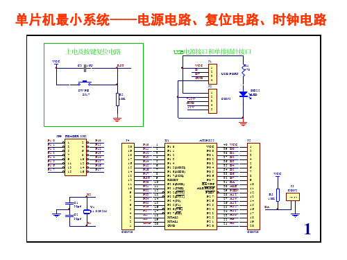
ICExplorer系列单片机仿真系统简介
ICExplorer系列单片机仿真系统简介ICExplorer系列单片机仿真系统是南京伟福实业有限公司开发的一种高性能,低价格的通用单片机开发工具. 可用于各种单片机的软硬件开发和调试. 它由ICExplorer仿真系统硬件与ICExplorer集成调试软件两部分组成.0.1 ICExplorer单片机仿真系统硬件●ICExplorer系列单片机仿真系统硬件采用大规模在线可编程芯片制造. 将整个单片机仿真控制电路、逻辑分析仪、总线跟踪、实时时效分析集成到一片大规模 ispPLD 芯片中, 仿真 CPU外置在仿真头上, 通过更换不同的仿真头,可对各种单片机进行仿真.●8位/16位兼容, 可仿真4位至16位单片机●采用专用仿真芯片及硬件断点技术, 不占用单片机任何资源. 在用户程序运行中, 可打入 CTRL-C 中断用户程序运行, 返回监控.●采用高速串口与计算机进行通信, 波特率自动设置. 最高波特率可达 115,200●逻辑分析仪可以实现各种复杂的组合断点和观察各种逻辑波形及分析时序关系,总线跟踪可以跟踪程序的运行轨迹。
0.2 ICExplorer集成调试软件●ICExplorer集成调试软件,具有编辑、汇编、编译、调试和软件模拟等功能,所有的操作均可通过窗口和菜单的选择来完成。
将软件命令和反映程序运行的情况集中在同一屏幕上的形式,称为集成环境,集成环境可以减少用户记忆众多命令的负担,方便用户编写和调试软件, 直观地反映程序运行情况, 提高软件的开发效率●支持Windows’95及Windows’98。
编辑器可以编辑超大型源文件(仅受硬盘大小限制)●支持汇编语言、PLM、C高级语言源程序调试●可观察数组、记录等各种复杂变量●支持屏幕取词. 用鼠标单击变量可直接察看该变量的当前值.●支持加亮显示. 当一个变量被修改后, 将以红色显示.●可进行软件模拟. 该软件可以用软件模拟的方式来调试用户编写的程序。
- 1、下载文档前请自行甄别文档内容的完整性,平台不提供额外的编辑、内容补充、找答案等附加服务。
- 2、"仅部分预览"的文档,不可在线预览部分如存在完整性等问题,可反馈申请退款(可完整预览的文档不适用该条件!)。
- 3、如文档侵犯您的权益,请联系客服反馈,我们会尽快为您处理(人工客服工作时间:9:00-18:30)。
EN Q1 S8050(NPN) EN MTMS MTDO MTDI MTCK S_TDI
VDD33
R_nTRST R_IO14 R_IO15 R_IO12 R_IO13
nRTSபைடு நூலகம்
R52
1K(1%)
Q2 S8050(NPN) IO0
Auto program DTR RTS-->EN IO0 1 1 1 1 0 0 1 1 1 0 0 1 0 1 1 0
GND R_IO26 R_IO23 R_IO21 R_IO34 R_IO36 R_IO18 R_IO4 R60 10K(1%) GND
RGB:
U6 R_IO2 R_IO0 R_IO4 3 2 1 3 2 1 5050RGB GND 4 5 6 4 5 6 LED_4 R149 LED_5 R150 LED_6 R151 470R(1%) 470R(1%) 470R(1%)
Support ESP32 Module: compatible old and new module
D1 GND VDD33 EN SENSOR_VP SENSOR_VN IO34 IO35 R_IO32 R_IO33 IO25 IO26 IO27 IO14 IO12 1 1 1 1 TP4 TP3 TP2 TP1 1 2 3 4 5 6 7 8 9 10 11 12 13 14 ESP32_MODULE GND3 IO23 IO22 TXD0 RXD0 IO21 IO20 IO19 IO18 IO5 IO17 IO16 IO4 IO0 38 37 36 35 34 33 32 31 30 29 28 27 26 25 GND IO23 IO22 TXD0 RXD0 IO21 C6 IO19 IO18 IO5 IO17 IO16 IO4 IO0 C7 100uF/6.3V(20%)1uF/10V(10%) C9 1nF/50V(10%)
5
4
3
2
1
Serial-Port:
VDD33 VDD1V8 L1 L2 1K@100MHZ 1K@100MHZ C1 C2 C3 C4 U1 VDD33 12 37 64 20 31 42 56 4 9 4.7uF/25V 4.7uF/25V 0.1uF/25V 0.1uF/25V
ESP32-Module:
SPI:
R_SD3 R_SD1 R_CLK JP13 1 2 3 1 2 3 6 5 4 6 5 4 R_SD2 R_CMD R_SD0 CON3X2_2P54
C
Switch:
R_IO13 R_IO15 JP14 1 2 1 2 3 4 3 4 nRTS nCTS nDTR R46 1K(1%) CON2X2_2P54
PWREN# SUSPEND#
10
1 5 11 15 25 35 47 51
R37/0R :ON 32K-CLK:R36/0R、 R38/0R、 R39/0R :OFF
GPIO:R36/0R、 R37/0R :OFF R38/0R、 R39/0R :ON
GND FT_GPIO3 GND FT_GPIO2 FT_GPIO1 VDD1V8 VDD1V8 VDD1V8 VDD33 VDD33 VDD33 VDD33 FT_GPIO0 C15 C16 C17 C18 C19 C20 C21 GND R40 R41 R42 2K(1%) 2K(1%) 2K(1%) D10 1 D11 1 D12 1 RED LED 2 RED LED 2 RED LED 2 R39 2K(1%) D9 1 RED LED 2
EECS EECLK EEDATA OSCI OSCO TEST AGND GND1 GND2 GND3 GND4 GND5 GND6 GND7 GND8
1 1 1
TP5 TP6 TP7 2K(1%) 2K(1%)
VDD33 U2 GND VDD33 EN 0R(1%) IO36 SENSOR_VP 0R(1%) IO39 SENSOR_VN 0R(1%) IO34 0R(1%) IO35 R_IO32 R_IO33 0R(1%) IO25 0R(1%) IO26 0R(1%) IO27 0R(1%) IO14 0R(1%) IO12 GND 0R(1%) IO13 0R(1%) SD2 0R(1%) SD3 0R(1%) CMD 1 2 3 4 5 6 7 8 9 10 11 12 13 14 15 16 17 18 19 GND1 3V3 EN SENSOR_VP SENSOR_VN IO34 IO35 IO32 IO33 IO25 IO26 IO27 IO14 IO12 GND2 IO13 SD2 SD3 CMD GND3 IO23 IO22 TXD0 RXD0 IO21 IO20 IO19 IO18 IO5 IO17 IO16 IO4 IO0 IO2 IO15 SD1 SD0 CLK 38 37 36 35 34 33 32 31 30 29 28 27 26 25 24 23 22 21 20 GND IO23 R10 IO22 R13 TXD0 RXD0 IO21 R21 IO19 IO18 IO5 IO17 IO16 IO4 IO0 IO2 IO15 SD1 SD0 CLK R25 R26 R28 R146 R147 R34 R148 R30 R38 R143 R144 R145 0R(1%) 0R(1%) 0R(1%) 0R(1%) 0R(1%) 0R(1%) 0R(1%) 0R(1%) 0R(1%) 0R(1%) 0R(1%) 0R(1%) 0R(1%) 0R(1%) 0R(1%) R_IO23 R_IO22 R_IO21 R_IO19 R_IO18 R_IO5 R_IO17 R_IO16 R_IO4 R_IO0 R_IO2 R_IO15 R_SD1 R_SD0 R_CLK 32K_XP R11 0R(1%) R_IO32 R12 0R(1%)(NC) IO32
16 17 18 19 21 22 23 24 26 27 28 29 30 32 33 34 38 39 40 41 43 44 45 46 48 52 53 54 55 57 58 59 60 36
VCORE1 VCORE2 VCORE3
TCK TDI TDO TMS nTRST R_DBGRQ R118 R_RTCK R119 R_DBGACKR120 R_RST R121 0R(1%)(NC) DBGRQ 0R(1%)(NC) RTCK 0R(1%)(NC) DBGACK 0R(1%)(NC) RST
R_IO13 R_SD2 R_SD3 R_CMD
GND
GND
ESP32_MODULE_2COL
0.1uF/25V 0.1uF/25V 0.1uF/25V
C
0.1uF/25V 0.1uF/25V 0.1uF/25V 0.1uF/25V GND GND GND GND
GND
GND
GND
JTAG:
When you use JTAG: Please put Jumpers ON!
D
VPHY VPLL
VCCIO1 VCCIO2 VCCIO3 VCCIO4
VDD33
CON4X2_2P54 GND
USB_DM USB_DP
GND
GND
EECS EECLK EEDATA VDD33
R6 R7 R8
63 33R(1%) R_EECS 33R(1%) R_EECLK 62 R_EEDATA 61 33R(1%) OSCI 2 3 13
GND2 IO13 SD2 SD3 CMD CLK SD0 SD1 IO15 IO2
D2
1N5819
GND1 3V3 EN SENSOR_VP SENSOR_VN IO34 IO35 IO32 IO33 IO25 IO26 IO27 IO14 IO12
R1 VDD33 5K(1%)(NC) 12K(1%) EN IO2 R3 5K(1%)(NC) GND GND GND GND IO0 RXD TXD 1 2 3 4 JP11 1 2 3 4 8 7 6 5 8 7 6 5 TXD0 RXD0
GND IO13 SD2 SD3 CMD CLK SD0 SD1 IO15 IO2
15 16 17 18 19 20 21 22 23 24
XO2 1 C12 27pF/50V
32.768KHz 32K_XN R23 2 C13 27pF/50V
0R(1%)
R_IO33 R24
0R(1%)(NC)
IO33
Please place near IC-Pins.
VDD33
VDD33
VDD33 R2
Micro USB 5V&USB-UART
GND
GND C5 C8
GND 4.7uF/25V 4.7uF/25V
GND VDD33 50 VDD1V8 49 VREGIN
GND GND
D
USB_5V J1 6 7 8 9 GND VBUS GND DGND D+ GND NC GND USB_CON8 ESD05V88D-LC ESD05V88D-LC 1 2 3 4 5 USB_PWR DD+
1 3 5 7 9 11 13
JP4 R_IO27 R_IO25 R_IO22 R_IO35 R_IO39 R_IO19 R_IO5 R_IO2 SIO_C VSYNC PCLK D7 D5 D3 D1 RESET 1 3 5 7 9 11 13 15 17 1 3 5 7 9 11 13 15 17 2 4 6 8 10 12 14 16 18 2 4 6 8 10 12 14 16 18 SIO_D HREF XCLK D6 D4 D2 D0 PWDN
Camera:
VDD33 VDD33 JP8 1 3 5 7 9 11 13 2 4 6 8 10 12 14 2 4 6 8 10 12 14 nTRST TMS TDO TDI TCK TDI MTCK MTDI MTDO MTMS EN R_IO13 R50 R_IO12 R54 R_IO15 R69 R_IO14 R55 R_nTRST R58 10K(1%) 10K(1%)(NC) 10K(1%)(NC) 10K(1%) 10K(1%) GND GND
