WP710A10SURCE;中文规格书,Datasheet资料
B0540WS-7;中文规格书,Datasheet资料
SURFACE MOUNT SCHOTTKY BARRIER RECTIFIERFeatures• Low Forward Voltage Drop• Guard Ring Construction for Transient Protection • High Conductance• Lead Free By Design/RoHS Compliant (Note 3) • "Green" Device (Note 4)Mechanical Data• Case: SOD-323• Case Material: Molded Plastic, "Green" Molding Compound.UL Flammability Rating Classification 94V-0• Moisture Sensitivity: Level 1 per J-STD-020D• Polarity: Cathode Band• Terminals: Finish - Matte Tin Annealed Over Alloy 42leadframe. Solderable per MIL-STD-202, Method 208 • Marking Information: See Page 2• Ordering Information: See Page 2• Weight: 0.004 grams (approximate)Top ViewMaximum Ratings@T A = 25°C unless otherwise specifiedSingle phase, half wave, 60Hz, resistive or inductive load.For capacitance load, derate current by 20%.Characteristic Symbol Value UnitPeak Repetitive Reverse Voltage Working Peak Reverse Voltage DC Blocking Voltage V RRMV RWMV R40 VRMS Reverse Voltage V R(RMS)28 V Average Rectified Output Current I O0.5 ANon-Repetitive Peak Forward Surge Current8.3ms single half sine-wave superimposed on rated load I FSM3 A Thermal CharacteristicsCharacteristic Symbol Value Unit Power Dissipation (Note 1) P D235 mW Typical Thermal Resistance Junction to Ambient (Note 1) RθJA426 °C/W Operating and Storage Temperature Range T J, T STG-40 to +125 °CElectrical Characteristics@T A = 25°C unless otherwise specifiedCharacteristic Symbol Min Typ Max Unit Test Condition Reverse Breakdown Voltage (Note 2) V(BR)R40 ⎯⎯V I R = 1mAForward Voltage V F⎯285480300550mVI F = 10mAI F = 500mAReverse Current (Note 2) I R ⎯⎯1.02.035μAμAV R = 10VV R = 30VTotal Capacitance C T ⎯⎯12520⎯⎯pFpFV R = 0V, f = 1.0MHzV R = 10V, f = 1.0MHzNotes: 1. Part mounted on FR-4 PC board with recommended pad layout, which can be found on our website at /datasheets/ap02001.pdf.2. Short duration pulse test used to minimize self-heating effect.3. No purposefully added Lead.4. Diodes Inc.'s "Green" policy can be found on our website at /products/lead_free/index.php.Please click here to visit our online spice models database.10100V, INSTANTANEOUS REVERSE VOLTAGE (V)Fig. 2 Typical Reverse CharacteristicsRI,INSTANTANEOUSFORWARDCURRENT(mA)FV, INSTANTANEOUS FORWARD VOLTAGE (V)Fig. 1 Typical Forward CharacteristicsF100C,TOTALCAPACITANCE(pF)TV, DC REVERSE VOLTAGE (V)Fig. 3 Total Capacitance vs. Reverse VoltageR0.250.50050100I,AVE150RAGEFORWARDCURRENT(A)F(AV)T, TERMINAL TEMPERATURE (C)Fig. 4 Forward Current Derating CurveT°0.751.02575125Ordering Information(Note 5)Part Number Case PackagingB0540WS-7 SOD-323 3000/Tape & ReelNotes: 5. For packaging details, go to our website at /datasheets/ap02007.pdf.Marking InformationSF SF = Product Type Marking CodePackage Outline DimensionsSuggested Pad LayoutIMPORTANT NOTICEDiodes Incorporated and its subsidiaries reserve the right to make modifications, enhancements, improvements, corrections or other changes without further notice to any product herein. Diodes Incorporated does not assume any liability arising out of the application or use of any product described herein; neither does it convey any license under its patent rights, nor the rights of others. The user of products in such applications shall assume all risks of such use and will agree to hold Diodes Incorporated and all the companies whose products are represented on our website, harmless against all damages.LIFE SUPPORTDiodes Incorporated products are not authorized for use as critical components in life support devices or systems without the expressed written approval of the President of Diodes Incorporated.SOD-323 Dim Min Max A 0.25 0.35 B 1.20 1.40 C 2.30 2.70 H 1.60 1.80 J 0.00 0.10 K 1.0 1.1 L0.20 0.40 M 0.10 0.15α0° 8°All Dimensions in mmDimensions Value (in mm)Z 3.75 G 1.05 X 0.65 Y 1.35 C 2.40分销商库存信息: DIODESB0540WS-7。
10S保护板规格书

LT-PD16 SPEC
文件编号:LTW-QR-YF1962
8、保护板与电芯连接的注意事项 Matters need attention when connecting
警告:把保护板连接电芯,或从电池组拆下保护板时,必须遵守以下连接顺序与规定;如果不按要 求的顺序作业,会损坏保护板的元器件,从而导致保护板不能保护电芯,造成严重的后果。
连接到第8节电芯正极 Connected to the positive terminal of Cell 8.
连接到第9节电芯正极 Connected to the positive terminal of Cell 9.
连接到第10节电芯正极 Connected to the positive terminal of Cell 10.
3. 实物图 Views
2. 特点 Features
z 7~13 节电芯串联保护 Provides protection for
7~13 cells in series z 充 电 和 放 电 的 各 种 保 护 功 能 Provides
protections in charging and discharging z 电芯的硬件平衡处理,平衡电流可通过外部器件
灵活调整 Processes the balance between cells
smartly, the current of it can be set freely by external components.(此保护板无均衡功能;) z 硬 件 的 过 流 、 短 路 保 护 功 能 处 理 Deals with
LT-PD16 SPEC
7.连接方式Connection To The Board B+(红色线) K
NZH3V0B,115;NZH10C,115;NZH8V2B,115;NZH7V5C,115;NZH6V2B,115;中文规格书,Datasheet资料
thermal resistance from junction to solder point
Min Typ Max Unit
[1] -
-
250 K/W
[2] -
-
125 K/W
[3] -
-
70 K/W
[1] Device mounted on an FR4 PCB, single-sided copper, tin-plated, mounting pad for cathode 1 cm2. [2] Device mounted on a ceramic PCB, Al2O3, standard footprint. [3] Soldering point of cathode tab.
Version SOD123F
Table 4. Marking codes
Type number
Marking code
NZH3V0B
CH
NZH3V3A
CJ
NZH3V6B
CK
NZH3V9B
CL
NZH4V3B
CM
NZH4V7B
CN
NZH5V1B
CP
NZH5V6B
CQ
NZH6V2B
CR
NZH6V8B
CS
5. Limiting values
Table 5. Limiting values In accordance with the Absolute Maximum Rating System (IEC 60134).
Symbol Parameter
Conditions
Min
Max Unit
IF Ptot
NZHxxx
ZXMP10A17E6TA;中文规格书,Datasheet资料

(Note 1)
(Note 2) (Note 1) (Note 2)
Symbol PD
RθJA TJ, TSTG
Value 1.1 8.8 1.7 13.7 113 73
-55 to 150
Unit W mW/°C
°C/W °C
Notes:
1. For a device surface mounted on 25mm x 25mm x 1.6mm FR4 PCB with high coverage of single sided 1oz copper, in still air conditions; the device is measured when operating in a steady-state condition.
3 of 8
December 2009
© Diodes Incorporated
ADVANCE INFORMATION
A Product Line of Diodes Incorporated
ZXMP10A17E6
Electrical Characteristics @TA = 25°C unless otherwise specified
ADVANCE INFORMATION
A Product Line of Diodes Incorporated
ZXMP10A17E6
100V P-CHANNEL ENHANCEMENT MODE MOSFET
Please click here to visit our online spice models database.
Thermal Characteristics
A Product Line of Diodes Incorporated
GETAC UX10-EX 全强固式平板电脑 配件规格手册说明书

Rugged Mobile Computing SolutionsGETAC UX10-EX全强固式平板电脑配件规格手册神基电通强固机动一手掌控苏州办公室 (Getac中国区总部) 江苏省昆山市长江南路恒春巷路1号4楼 电话 +86-139-1710-9441北京办公室 中国北京市朝阳区北三环东路8号静安中心2606室 电话 +86-10-53670738上海办公室 上海市闸北区江场三路213号2楼 电话 +86-21-61401023*************************** I 标准电池4200MAH(1组)特点和优点附加电池组保证您能始终有充足的备用电池,以防在野外设备电源耗尽。
产品信息电池类型:锂离子电压11.1V容量:标准4200mAh;小4080mAh电池数目:3S2P尺寸:长140x宽136x高10.7mm重:305gSKU IDGBM6X4大容量电池9240MAH(1组)特点和优点相比标准电池,大容量电池将系统运行时间扩大至两倍,给需要额外电池寿命进行全天运算的移动专业人员提供更好的解决方案。
产品信息电池类型:锂离子电压10.8V容量:9240mAh电池数目:3S3P尺寸:长140x宽136x高21mm增加设备厚度:高度增加约11mm重:515gSKU IDGBM9X5双槽充电器特点和优点此外部双槽主电池充电器适用于2个主电池同时充电。
在空间和电源插座有限时,便于您同时进行两个主电池的充电和存放。
产品信息交流电输入:100V~240V直流电输出:大13.05V, 2.4A充电槽数目:2槽尺寸:长160x宽180x高72.5mm重:1.2kg支持主电池和高容量电池。
SKU IDGCMCEE (欧盟地区电源线)GCMCUE (美国地区电源线)GCMCKE (英国地区电源线)GCMCCE (中国大陆地区电源线)GCMCTE (台湾地区电源线)多槽充电器8槽特点和优点8槽充电器可同时对多个电池组充电,为用户提供了一个高效的充电解决方案。
LCB710;中文规格书,Datasheet资料
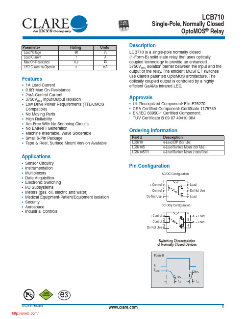
Applications
• Sensor Circuitry • Instrumentation • Multiplexers • Data Acquisition • Electronic Switching • I/O Subsystems • Meters (gas, oil, electric and water) • Medical Equipment-Patient/Equipment Isolation • Security • Aerospace • Industrial Controls
RoHS
2002/95/EC
DS-LCB710-R01
/
e3
Switching Characteristics of Normally Closed Devices
Form-B
IF ILOAD
10% toff
90% ton
1
Absolute Maximum Ratings @ 25ºC
Typical LED Forward Voltage Drop (N=50, TA=25ºC)
30
25
20
15
10
5
0 1.220 1.225 1.230 1.235 1.240 1.245 1.250 LED Forward Voltage (V)
Device Count (N)
PERFORMANCE DATA*
Ordering Information
Part # LCB710 LCB710S LCB710STR
Description 6-Lead DIP (50/Tube) 6-Lead Surface Mount (50/Tube) 6-Lead Surface Mount (1000/Reel)
EE-SX671;EE-SX674;EE-SX670A;EE-SX670P;EE-SX671A;中文规格书,Datasheet资料

T-shaped, slot center 10 mm F-shaped
Dark-ON/Light-ON Incident light (selectable) *3
EE-SX675
EE-SX675P
Dark-ON/Light-ON Incident light (selectable) *3 R-shaped Dark-ON/Light-ON Incident light (selectable) *3
EE-SX670 EE-SX671 EE-SX673 EE-SX674 Connector EE-SX675 EE-SX670A EE-SX671A EE-SX673A EE-SX674A models EE-SX470 EE-SX471 EE-SX473 EE-SX474 NPN Pre-wired EE-SX670EE-SX671EE-SX673EE-SX674EE-SX675models models WR WR WR WR WR Models with EE-SX670EE-SX671EE-SX673EE-SX674EE-SX675connectors CJ1-R CJ1-R CJ1-R CJ1-R CJ1-R EE-SX670P EE-SX671P EE-SX673P EE-SX674P Connector EE-SX670R EE-SX675P EE-SX671R EE-SX673R EE-SX674R models EE-SX470P EE-SX471P EE-SX473P EE-SX474P PNP Pre-wired EE-SX670PEE-SX671PEE-SX673PEE-SX674PEE-SX675Pmodels models WR WR WR WR WR Models with EE-SX670PEE-SX671PEE-SX673PEE-SX674PEE-SX675PItem connectors CJ1-R CJ1-R CJ1-R CJ1-R CJ1-R Sensing distance 5 mm (slot width) Sensing object Opaque: 2 × 0.8 mm min. Differential distance 0.025 mm Light source GaAs infrared LED with a peak wavelength of 940 nm Indicator *1 Light indicator (red) (turns ON when light is interrupted for models with A or R suffix) Supply voltage 5 to 24 VDC ±10%, ripple (p-p): 10% max. Current consumption 35 mA max. (NPN models), 30 mA max. (PNP models) NPN open collector: 5 to 24 VDC, 100 mA max. 100 mA load current with a residual voltage of 0.8 V max. 40 mA load current with a residual voltage of 0.4 V max. Control output OFF current: 0.5 mA max. PNP open collector: 5 to 24 VDC, 50 mA max. 50 mA load current with a residual voltage of 1.3 V max. OFF current: 0.5 mA max. Response frequency *2 1 kHz min. (3 kHz average) Ambient illumination 1,000 lx max. with fluorescent light on the surface of the receiver. Ambient temperature range Operating: −25 to +55°C, Storage: −30 to +80°C (with no icing or condensation) Ambient humidity range Operating: 5% to 85%, Storage: 5% to 95% (with no icing or condensation) Destruction: 20 to 2,000 Hz (peak acceleration: 100 m/s2) Vibration resistance 1.5-mm double amplitude for 2 h (4-min periods) each in X, Y, and Z directions Shock resistance Destruction: 500 m/s2 for 3 times each in X, Y, and Z directions Degree of protection IEC60529 IP50 Connector Models (direct soldering possible), Pre-wired Models (Standard cable length: 1 m), Connecting method Models with Connectors (Standard cable length: 0.1 m) Connector models Approx. 3.1 g Approx. 3 g Approx. 2.4 g Approx. 2.3 g Approx. 3 g Approx. 2.7 g Wei- Pre-wired models Approx. 18.9 g Approx. 17.3 g Approx. 17.8 g Approx. 16.8 g Approx. 17.1 g Approx. 18.3 g ght Models with Approx. 6.3 g Approx. 4.7 g Approx. 5.2 g Approx. 4.2 g Approx. 4.5 g Approx. 5.7 g connectors Case Polybutylene phthalate (PBT) Materi- Cover Polycarbonate al Emitter/receiver *1. The indicator is a GaP red LED (peak wavelength: 690 nm). *2. The response frequency was measured by detecting the rotating disk shown at the right.
7寸高清屏40PIN-LVDS
R O F
6.4. Storage ......................................................................................................................... 18 6.5. Cleaning ....................................................................................................................... 18
Module No.: FW070TFT-VH40
Page:1/21
1. General Specifications
No. 1 2 3 4 5 6 7 8 9 10 11 12 13 LCD size Driver element Resolution Display mode Dot pitch Active area Module size Surface treatment Color arrangement Interface Backlight power Backlight power consumption Item Specification 7.0 inch(Diagonal) a-Si TFT active matrix 1024 × 3(RGB) × 600 Normally White, Transmissive 0.05(W) × 0.15(H) mm 153.6(W) × 90.0(H) mm 165.75 (W) ×105.39(H) ×2.8(D) mm Anti-glare, Glare RGB-stripe Note 1 Remark
WP710A10SRCE;中文规格书,Datasheet资料

Electrical / Optical Characteristics at TA=25°C
Symbol λpeak λD [1] Δλ1/2 C VF [2] IR Parameter Peak Wavelength Dominant Wavelength Spectral Line Half-width Capacitance Forward Voltage Reverse Current Device Super Bright Red Super Bright Red Super Bright Red Super Bright Red Super Bright Red Super Bright Red Typ. 660 640 20 45 1.85 2.5 10 Max. Units nm nm nm pF V uA Test Conditions IF=20mA IF=20mA IF=20mA VF=0V;f=1MHz IF=20mA VR = 5V
Super Bright Red
WP710A10SRC/E
SPEC NO: DSAL0548 APPROVED: WYNEC
REV NO: V.2 CHECKED: Allen Liu
DATE: MAR/07/2011 DRAWN: J.Yu
PAGE: 3 OF 6 ERP: 1101029119
T-1 (3mm) SOLID STATE LAMP
Part Number: WP710A10SRC/E Super Bright Red
Hale Waihona Puke Featuresz Low power consumption. z Popular T-1 diameter package. z General purpose leads. z Reliable and rugged. z Long life - solid state reliability. z Available on tape and reel. z RoHS compliant.
M710e 用户指南和硬件维护手册说明书

第 3 章 计算机锁. . . . . . . . . . . . 9
锁住计算机外盖 . . . . . . . . . . . . . . 9 连接 Kensington 式钢缆锁 . . . . . . . . 10 连接钢缆锁 . . . . . . . . . . . . . . . 11
图 7. 连接钢缆锁
第 3 章 . 计 算 机 锁 11
12 M710e 用户指南和硬件维护手册
第 4 章 更换硬件
本章提供如何为您的计算机更换硬件的说明。
更换硬件之前
注意:打开计算机或尝试进行任何修理之前,请先阅读本节和《重要产品信息指南》。
更换硬件之前需要注意的事项 • 仅使用 Lenovo 提供的计算机组件。 • 安装或更换选件时,请使用本手册中列出的相应说明以及随选件附带的说明。 • 在全世界大部分地区,Lenovo 都要求退回有问题的 CRU。CRU 附带有关此事宜的信息,或将
2 M710e 用户指南和硬件维护手册
后视图
注:您的计算机型号可能与插图略有不同。
图 2. 后视图
1 音频输出接口 3 VGA 输出接口 5 USB 3.1 Gen 1 接口(2) 7 串口 9 线缆锁插槽 (2) 11 安全锁插槽 13 PCI-Express 卡区域
2 DisplayPort® 输出接口 4 USB 2.0 接口(2) 6 电源线接口 8 以太网接口 10 挂锁环 12 串口(选配)
图 1. 前视图
1 光盘驱动器弹出/关闭按钮 3 内置扬声器(选配) 5 读卡器插槽(选配) 7 电源按钮
2 光盘驱动器状态指示灯 4 存储驱动器状态指示灯 6 电源指示灯 8 麦克风接口
10A10

10A10
10A10在R-6封装里采用的1个芯片,是一款轴向大电流整流二极管。
10A10的浪涌电流Ifsm为600A,漏电流(Ir)为
10uA,其工作时耐温度范围为-55~150摄氏度。
10A10采用GPP硅芯片材质,里面有1颗芯片组成。
10A10的电性参数是:正向电流(Io)为10A,反向耐压为1000V,正向电压(VF)为1.0V,其中有2条引线。
10A10参数描述
型号:10A10
封装:R-6
特性:轴向大电流整流二极管
电性参数:10A 1000V
芯片材质:GPP
正向电流(Io):10A
芯片个数:1
正向电压(VF):1.0V
浪涌电流Ifsm:600A
漏电流(Ir):10uA
工作温度:-55~+150℃
引线数量:2
10A10轴向大电流封装系列。
它的本体长度为9.1mm,加引脚长度为59.9mm,宽度为9.1mm,高度为9.1mm。
10A10拥有低正向压降、低反向漏电流、高正向浪涌电流能力等特点。
波士顿家用电器官方网站商品说明书

Accessories: To purchase Bosch accessories, cleaners & parts please visit /us/store or call 1-800-944-2904 (Mon to Fri 5 am to 6 pm PST, Sat 6 am to 3 pm PST).SHXM78Z54N Black Stainless Steel Also available in:Stainless Steel SHXM78Z55N White SHXM78Z52N BlackSHXM78Z56NPatented CrystalDry™ technology transforms moisture into heat to get dishes, including plastics, 60% drier.142 dBA: dishwasher runs quietly so your kitchen conversations aren’t interrupted.The Flexible 3rd Rack with fold down sides adds 30% more 2 loading area, perfect for utensils and ramekins.The AquaStop® leakprotection system contains leaks through a precisely engineered system. If a leak occurs, the system contains it by shutting down operation andpumping out water. So you have the ultimate peace of mind whether you are away or at home.1Based on aggregate average drying performance of Bosch Dishwashers with CrystalDry on combined household load including plastics, glass, steel, and porcelain as compared to Bosch Dishwashers with PureDry. Drying performance may vary by dish type.2Compared to a Bosch dishwasher with 2 racks.3Certification to NSF/ANSI Standard 184 for residential dishwashers. 4September 2020 running production change to remove adhesive routing clips for power cord. These clips and the edge protector are now included in the dishwasher accessory kit # SMZEPCC1UC.Accessories: To purchase Bosch accessories, cleaners & parts please visit /us/store or call 1-800-944-2904 (Mon to Fri 5 am to 6 pm PST, Sat 6 am to 3 pm PST).Installation DetailsJunction box accessoryInstallation DetailsAccessories: To purchase Bosch accessories, cleaners & parts please visit /us/store or call 1-800-944-2904 (Mon to Fri 5 am to 6 pm PST, Sat 6 am to 3 pm PST).。
AT070TN92 群创7寸屏datasheet
INNO L U X DISPLAY CORPORATIONLCD MODULESPECIFICATIONCustomer:Model Name: AT070TN92SPEC NO.: A070-92-TT-02Date: 2009/06/22Version: 02■Preliminary Specification□Final SpecificationFor Customer’s AcceptanceApproved by CommentApproved by Reviewed by Prepared byJoe Lin2009/06/23James Yu2009/06/22David Lee2009/06/22InnoLux copyright 2004All rights reserved,Copying forbidden.Record of RevisionVersion Revise Date Page ContentPre-Spec.01 2009/01/12 Initial Release02 2009/06/22 1 Add B/L & Panel power consumption.6 Add Vcom value.7Add current consumption.Update backlight driving condition.I NNO L U XContents1. General Specifications (1)2. Pin Assignment (2)3. Operation Specifications (5)3.1. Absolute Maximum Rating (5)3.1.1. Typical Operation Conditions (6)3.1.2. Current Consumption (7)3.1.3. Backlight Driving Conditions (7)3.2. Power Sequence (8)3.3. Timing Characteristics (9)3.3.1. AC Electrical Characteristics (9)3.3.2. Data Input Format (10)3.3.3. Timing (11)4. Optical Specifications (12)5. Reliability Test Items (16)6. General Precautions (17)6.1. Safety (17)6.2. Handling (17)6.3. Static Electricity (17)6.4. Storage (17)6.5. Cleaning (17)7. Mechanical Drawing (18)8. Package Drawing (19)8.1 Packaging Material Table (19)8.2 Packaging Quantity (19)8.3 Packaging Drawing (20)1. General SpecificationsNo. Item Specification Remark1 LCD size 7.0 inch(Diagonal)2 Driver element a-Si TFT active matrix3 Resolution 800 × 3(RGB) × 4804 Display mode Normally White, Transmissive5 Dot pitch 0.0642(W) × 0.1790(H) mm6 Active area 154.08(W) × 85.92(H) mm7 Module size 164.9(W) ×100.0(H) ×5.7(D) mm Note 18 Surface treatment Anti-Glare9 Color arrangement RGB-stripe10 Interface Digital11 Backlight power consumption 1.674W (Typ.)12 Panel power consumption 0.226W (Typ.)13 Weight (150g) (Typ.)Note 1: Refer to Mechanical Drawing.2. Pin AssignmentTFT LCD Panel Driving SectionFPC Connector is used for the module electronics interface. The recommended model is FH12A-50S-0.5SH manufactured by Hirose.Pin No. Symbol I/O Function Remark1 V LED+P Power for LED backlight (Anode)2 V LED+P Power for LED backlight (Anode)3 V LED-P Power for LED backlight (Cathode)4 V LED-P Power for LED backlight (Cathode)5 GND P Power ground6 V COM I Common voltage7 DV DD P Power for Digital Circuit8 MODE I DE/SYNC mode select Note 19 DE I Data Input Enable10 VS I Vertical Sync Input11 HS I Horizontal Sync Input12 B7 I Blue data(MSB)13 B6 I Blue data14 B5 I Blue data15 B4 I Blue data16 B3 I Blue data17 B2 I Blue data18 B1 I Blue data Note 219 B0 I Blue data(LSB) Note 220 G7 I Green data(MSB)21 G6 I Green data22 G5 I Green data23 G4 I Green data24 G3 I Green data26 G1 I Green data Note 227 G0 I Green data(LSB) Note 228 R7 I Red data(MSB)29 R6 I Red data30 R5 I Red data31 R4 I Red data32 R3 I Red data33 R2 I Red data34 R1 I Red data Note 235 R0 I Red data(LSB) Note 236 GND P Power Ground37 DCLK I Sample clock Note 338 GND P Power Ground39 L/R I Left / right selection Note 4,540 U/D I Up/down selection Note 4,541 V GH P Gate ON Voltage42 V GL P Gate OFF Voltage43 AV DD P Power for Analog Circuit44 RESET I Global reset pin. Note 645 NC - No connection46 V COM I Common Voltage47 DITHB I Dithering function Note 748 GND P Power Ground49 NC - No connection50 NC - No connectionI: input, O: output, P: PowerNote 1: DE/SYNC mode select. Normally pull high.When select DE mode, MODE=”1”, VS and HS must pull high.When select SYNC mode,MODE= ”0”, DE must be grounded.Note 2: When input 18 bits RGB data, the two low bits of R,G and B data must be grounded.Note 3:Data shall be latched at the falling edge of DCLK.Note 4: Selection of scanning modeSetting of scan control inputU/D L/RScanning directionGND DV DD Up to down, left to rightDV DD GND Down to up, right to leftGND GND Up to down, right to leftDV DD DV DD Down to up, left to rightNote 5: Definition of scanning direction.Refer to the figure as below:Note 6: Global reset pin. Active low to enter reset state. Suggest to connect with an RC reset circuit for stability. Normally pull high.Note 7: Dithering function enable control, normally pull high.When DITHB=”1”,Disable internal dithering function,When DITHB=”0”,Enable internal dithering function,RightLeftDownUp3. Operation Specifications3.1. Absolute Maximum Ratings(Note 1)ValuesItem SymbolMin. Max.Unit RemarkDV DD -0.3 5.0 VAV DD 6.5 13.5 VV GH -0.3 40.0 VV GL -20.0 0.3 V Power voltageV GH-V GL- 40.0 V Operation Temperature T OP -20 70 ℃Storage Temperature T ST-30 80 ℃LED Reverse Voltage V R- 1.2 VEach LEDNote 2 LED Forward Current I F- 25 mA Each LEDNote 1: The absolute maximum rating values of this product are not allowed to be exceeded at any times. Should a module be used with any of the absolute maximum ratingsexceeded, the characteristics of the module may not be recovered, or in an extremecase, the module may be permanently destroyed.Note 2: V R Conditions: Zener Diode 20mA3.1.1. Typical Operation Conditions( Note 1)ValuesUnit Remark Item SymbolMin. Typ. Max.DV DD 3.0 3.3 3.6 V Note 2AV DD 10.2 10.4 10.6 VPower voltageV GH 15.3 16.0 16.7 VV GL -7.7 -7.0 -6.3 VInput signal voltage V COM 3.8 4.0 4.2 VInput logic high voltage V IH 0.7 DV DD - DV DD VNote 3 Input logic low voltage V IL 0 - 0.3 DV DD VNote 1: Be sure to apply DV DD and V GL to the LCD first, and then apply V GH.Note 2: DV DD setting should match the signals output voltage (refer to Note 3) of customer’s system board.Note 3: DCLK,HS,VS,RESET,U/D, L/R,DE,R0~R7,G0~G7,B0~B7,MODE,DITHB.3.1.2. Current ConsumptionValuesItem SymbolMin. Typ. Max.Unit RemarkI GH - 0.2 1.0 mA V GH =16.0VI GL - 0.2 1.0 mA V GL = -7.0V IDV DD - 4.0 10 mA DV DD =3.3VCurrent for DriverIAV DD - 20 50 mA AV DD =10.4V3.1.3. Backlight Driving ConditionsValuesItem SymbolMin. Typ. Max.Unit Remark Voltage for LED backlight V L 8.7 9.3 9.9 V Note 1 Current for LED backlight I L 170 180 200 mALED life time - 20,000 - - Hr Note 2Note 1: The LED Supply Voltage is defined by the number of LED at Ta=25℃ andI L =180mA.Note 2: The “LED life time” is defined as the module brightness decrease to 50% original brightness at Ta=25℃ and I L =180mA. The LED lifetime could be decreased ifoperating I L is lager than 180mA.3.2. Power Sequencea. Power on:Note: Data include R0~R7, B0~B7, GO~G7, U/D, L/R, DCLK, HS,VS,DE.DV DD→VGL→VGH→Data→B/LB/L→Data→VGH→VGL→DV DD3.3. Timing Characteristics3.3.1. AC Electrical CharacteristicsValuesItem SymbolMin. Typ. Max.Unit Remark HS setup time T hst8 - - nsHS hold time T hhd 8 - - nsVS setup time T vst8 - - nsVS hold time T vhd8 - - nsData setup time T dsu8 - - nsData hole time T dhd8 - - nsDE setup time T esu 8 - - nsDE hole time T ehd8 - - nsDV DD Power On Slew rate T POR - - 20 ms From 0 to 90% DV DDRESET pulse width T Rst 1 - - ms DCLK cycle time T coh 20 - - ns DCLK pulse duty T cwh 40 50 60 %3.3.2. Data Input Format3.3.3. TimingValuesUnit Remark Item SymbolMin. Typ. Max.Horizontal Display Area thd- 800 - DCLKDCLK Frequency fclk26.4 33.3 46.8 MHzOne Horizontal Line th862 1056 1200 DCLKHS pulse width thpw 1 - 40 DCLKHS Blanking thb46 46 46 DCLKHS Front Porch thfp 16 210 354 DCLKValuesItem SymbolUnit RemarkMin. Typ. Max.Vertical Display Area tvd- 480 - THVS period time tv 510 525 650 THVS pulse width tvpw 1 - 20 THVS Blanking tvb23 23 23 THVS Front Porch tvfp 7 22 147 TH4. Optical SpecificationsValuesItem Symbol ConditionMin. Typ. Max.Unit RemarkθL Φ=180°(9 o’clock) 60 70 -θRΦ=0°(3 o’clock) 60 70 -θTΦ=90°(12 o’clock) 40 50 -Viewing angle(CR≥ 10)θBΦ=270°(6 o’clock) 60 70 -degree Note 1T ON - 10 20 msec Note 3 Response timeT OFF - 15 30 msec Note 3 Contrast ratio CR 400 500 - - Note 4W X 0.26 0.31 0.36 -Color chromaticityW Y 0.28 0.33 0.38 -Note 2Note 5Note 6 Luminance L 200 250 - cd/m² Note 6 LuminanceuniformityY UNormalθ=Φ=0°70 75 - % Note 7Test Conditions:1. DV DD=3.3V, I L=180mA (Backlight current), the ambient temperature is 25℃.2. The test systems refer to Note 2.Note 1: Definition of viewing angle rangeFig. 4-1 Definition of viewing angle Note 2: Definition of optical measurement system.The optical characteristics should be measured in dark room. After 30 minutesoperation, the optical properties are measured at the center point of the LCD screen. (Response time is measured by Photo detector TOPCON BM-7, other items are measured by BM-5A/Field of view: 1° /Height: 500mm.)Fig. 4-2 Optical measurement system setupNormal line θ=Φ=0°Photo detectorΦ=90°12 o’clock directionΦ=270°6 o’clock directionΦ=0°Φ=180°Active Area500mmLCMNormal line θ=Φ=0°Φ=90°12 o’clock directionΦ=270° 6 o’clock directionΦ=0°Φ=180°Active AreaθLθTθBθRLCMNote 3: Definition of Response timeThe response time is defined as the LCD optical switching time interval between“White” state and “Black” state. Rise time (T ON) is the time between photo detector output intensity changed from 90% to 10%. And fall time (T OFF) is the timebetween photo detector output intensity changed from 10% to 90%.Fig. 4-3 Definition of response timeNote 4: Definition of contrast ratiostateBlack""theonLCDwhenmeasuredLuminancestateWhite""theonLCDwhenmeasuredLuminance(CR)ratioContrast=Note 5: Definition of color chromaticity (CIE1931)Color coordinates measured at center point of LCD.Note 6: All input terminals LCD panel must be ground while measuring the center area of the panel.The LED driving condition is I L=180mA .90%10%0%Photodetectoroutput(Relativevalue)ONTWhite (TFT OFF) Black (TFT ON) White (TFT OFF)Note 7:Definition of Luminance UniformityActive area is divided into 9 measuring areas (Refer to Fig. 4-4 ).Every measuring point is placed at the center of each measuring area.maxminBB(Yu)UniformityLuminance=L-------Active area length W----- Active area widthWW/3W/3W/6L/3L/3L/6LFig. 4-4 Definition of measuring pointsB max: The measured maximum luminance of all measurement position.B min: The measured minimum luminance of all measurement position.5. Reliability Test Items(Note3)Item Test Conditions Remark High Temperature Storage Ta = 80℃240hrs Note 1,Note 4 Low Temperature Storage Ta = -30℃240hrs Note 1,Note 4 High Temperature Operation Ts = 70℃240hrs Note 2,Note 4 Low Temperature Operation Ta = -20℃240hrs Note 1,Note 4 Operate at High Temperatureand Humidity+60℃, 90%RH 240hrs Note 4Thermal Shock -30℃/30 min ~ +80℃/30 min for a total 100cycles, Start with cold temperature and endwith high temperature.Note 4Vibration Test Frequency range:10~55Hz Stroke:1.5mmSweep:10Hz~55Hz~10Hz2 hours for each direction of X. Y. Z.(6 hours for total)Mechanical Shock 100G 6ms,±X, ±Y, ±Z 3 times for each directionPackage Vibration Test Random Vibration :0.015G*G/Hz from 5-200HZ, -6dB/Octave from 200-500HZ2 hours for each direction of X. Y. Z.(6 hours for total)Package Drop Test Height:60 cm1 corner, 3 edges, 6 surfacesElectro Static Discharge ± 2KV, Human Body Mode, 100pF/1500ΩNote 1: Ta is the ambient temperature of samples.Note 2: Ts is the temperature of panel’s surface.Note 3: In the standard condition, there shall be no practical problem that may affect the display function. After the reliability test, the product only guarantees operation,but don’t guarantee all of the cosmetic specification.Note 4: Before cosmetic and function test, the product must have enough recovery time, at least 2 hours at room temperature.6. General Precautions6.1. SafetyLiquid crystal is poisonous. Do not put it in your mouth. If liquid crystal touches your skin or clothes, wash it off immediately by using soap and water.6.2. Handling1. The LCD panel is plate glass. Do not subject the panel to mechanical shock or toexcessive force on its surface.2. The polarizer attached to the display is easily damaged. Please handle it carefullyto avoid scratch or other damages.3. To avoid contamination on the display surface, do not touch the module surfacewith bare hands.4. Keep a space so that the LCD panels do not touch other components.5. Put cover board such as acrylic board on the surface of LCD panel to protect panelfrom damages.6. Transparent electrodes may be disconnected if you use the LCD panel underenvironmental conditions where the condensation of dew occurs.7. Do not leave module in direct sunlight to avoid malfunction of the ICs.6.3. Static Electricity1. Be sure to ground module before turning on power or operating module.2. Do not apply voltage which exceeds the absolute maximum rating value.6.4. Storage1. Store the module in a dark room where must keep at 25±10℃ and 65%RH or less.2. Do not store the module in surroundings containing organic solvent or corrosivegas.3. Store the module in an anti-electrostatic container or bag.6.5. Cleaning1. Do not wipe the polarizer with dry cloth. It might cause scratch.2. Only use a soft sloth with IPA to wipe the polarizer, other chemicals mightpermanent damage to the polarizer.7. Mechanical Drawing8. Package Drawing8.1. Packaging Material TableNo. ItemModel(Material)Dimensions(mm)UnitWeight(kg)Quantity Remark1 LCMModuleAT070TN92 164.9 × 100.0 × 5.7 (0.150) 50pcs2 Partition BC Corrugatedpaper512 × 349 × 226 1.466 1set3 CorrugatedPaperB Corrugatedpaper510 × 350 0.071 4pcs4 CorrugatedBarB Corrugatedpaper512 × 11 × 3 0.046 4pcs5 Dust-ProofBagPE 700 × 530 0.048 1pcs6 A/S Bag PE 180 × 133 × 0.2 0.002 50pcs7 Carton Corrugatedpaper530 × 355 × 255 1.100 1pcs8 Total weight (10.682 kg± 5%)8.1 Packaging QuantityTotal LCM quantity in Carton: no. of Partition 2 Rows × quantity per Row 25 = 508.2 Packaging Drawing。
sbs battery at10系列电池充电器使用手册说明书
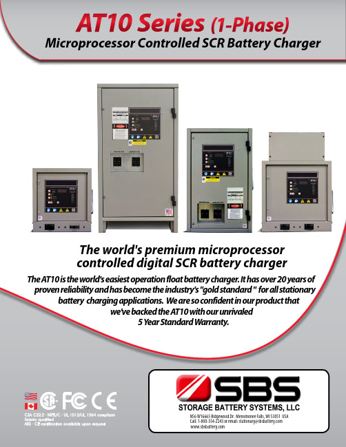
AT10 Series (1-Phase) Microprocessor Controlled SCR Battery ChargerThe world's premium microprocessorcontrolled digital SCR battery chargerThe AT10 is the world's easiest operation float battery charger. It has over 20 years of proven reliability and has become the industry's "gold standard " for all stationary battery charging applications. We are so confident in our product thatwe've backed the AT10 with our unrivaled5 Y ear Standard Warranty.N56 W16665 Ridgewood Dr. Menomonee Falls, WI 53051 USACall:1-800-554-2243oremail:*************************What are the most common applications for the AT10?SPECIFICATIONS &STANDARD FEATURESSPECIFICATIONSOPTIONS THAT LET YOU DESIGN YOUR CHARGER EXACTLY HOW YOU NEED IT!OPTIONS THAT LET YOU DESIGN YOUR CHARGER EXACTLY HOW YOU NEED IT!OPTIONS THAT LET YOU DESIGN YOUR CHARGER EXACTLY HOW YOU NEED IT!OPTIONS THAT LET YOU DESIGN YOUR CHARGER EXACTLY HOW YOU NEED IT!AT10 SERIESSPECIFICATION CHARTCabinet Style 5018Cabinet Style 5017Cabinet Style 5946-25AdcGR O U P1GR O U P2Ah x 1.Rt+L = AH=Ampere hours removedR= Recharge factor (1 = Pb) or (3 = NiCd)L= Additional standing load t= Recharge time in hours*NOTE: Dimensions shown are for reference only; for installation and mounting Continuous Charger Output Rating30-100AdcH O W T O S I Z E Y O U RC H A R G E R (s i m p l i fi e d fo r m u l a )G H J K LMicroprocessorControl BoardI/O AssemblyFilter AssemblyOutputCircuit BreakerInputCircuit BreakerMain InductorMainTransformerRectifier AssemblyGROUP 1*For chargers 16Adc and larger; consultfactory for other ratings.Input:PAGE 11I/O AssemblyOutput Circuit BreakerInput Circuit BreakerMain InductorMain TransformerRectifier AssemblyCircuit BreakerAC & DC Ratings5kAIC - 120/208/240/480Vac 5kAIC - 125VdcInput:Output:65kAIC - 120/208/240/480Vac25kAIC - 600Vac20kAIC - 250VdcInput:Output:25kAIC - 120/208/240/480Vac18kAIC - 600Vac10kAIC - 250VdcInput:Output:STANDARDMEDIUMHIGHSpecifications subject to change.YOUR CODEGROUP 2Rev. 06-13Standard Warranty(applies only to products delivered within the United States and Canada)All charger products are warranted to be free from defects in material and workmanship for a period of five (5) years from date of manufacture. During the term of the warranty period: parts, assemblies, or components deemed to be defective will be repaired or replaced at our option, free of charge. All costs related to removal, reinstallation and transportation will be paid by the purchaser/customer and/or operator of the product. Evaluation, repair and/or replacement of any defective part(s) are FOB manufacturer’s factory.This warranty does not cover products or parts that are damaged from improper use or abuse, as determined by the manufacturer. Accessory items or additional items carry only their respective manufacturer’s warranty. Consumable items (such as fuses and electrolytic capacitors), which wear out under normal use are specifically not covered by this standard warranty. Any consequential damage due to diagnosis or repair by any party other than the manufacturer's authorized personnel is not covered under this warranty.NOTE: Requests for returns or claims must be submitted to our Factory Service Center for Return Material Authorization (RMA) instructions and assignment. Returns that do not follow this procedure will not be honored.Extended warranty coverage available by request.SBS reserves the right to change specifications and designs without notice.Illustrations, data, dimensions and weights given in this brochure are for guidance only and cannot be held binding on the company.Other Products Available:AT30 Microprocessor Battery Charger AT Series Options & Accessories AT Series Communications Module AT-DC Series Distribution PanelSCR/SCRF Series Utility Battery ChargerUMC Universal Maintenance Charger Single Cell ChargerMobile DC Power System The EPIC Series Console Best Battery SelectorMobile DC Power System UniversalMaintenance Charger AT30 Microprocessor Battery Charger The EPIC Series ConsoleStorage Battery Systems, LLC N56 W16665 Ridgewood Drive Menomonee Falls, WI 53051 USA ****************************************••••。
Fairchild Semiconductor 商品说明书 FNB41060 Motion SPM

FNB41060FNB41060 Motion SPM® 45 SeriesJanuary 2014FNB41060Motion SPM ® 45 SeriesFeatures•UL Certified No. E209204 (UL1557)•600 V - 10 A 3-Phase IGBT Inverter with Integral Gate Drivers and Protection •Low Thermal Resistance Using Ceramic Substrate •Low-Loss, Short-Circuit Rated IGBTs•Built-In Bootstrap Diodes and Dedicated Vs Pins Sim-plify PCB Layout •Built-In NTC Thermistor for Temperature Monitoring •Separate Open-Emitter Pins from Low-Side IGBTs for Three-Phase Current Sensing •Single-Grounded Power Supply •Isolation Rating: 2000 V rms / min.Applications•Motion Control - Home Appliance / Industrial MotorRelated Resources•AN-9070 - Motion SPM® 45 Series Users Guide •AN-9071 - Motion SPM® 45 Series Thermal Perfor-mance Information •AN-9072 - Motion SPM® 45 Series Mounting Guid-ance •RD-344 - Reference Design (Three Shunt Solution)•RD-345 - Reference Design (One Shunt Solution)General DescriptionFNB41060 is a Motion SPM ® 45 module providing a fully-featured, high-performance inverter output stage for AC Induction, BLDC, and PMSM motors. These mod-ules integrate optimized gate drive of the built-in IGBTs to minimize EMI and losses, while also providing multi-ple on-module protection features including under-volt-age lockouts, over-current shutdown, thermal monitoring, and fault reporting. The built-in, high-speed HVIC requires only a single supply voltage and trans-lates the incoming logic-level gate inputs to the high-volt-age, high-current drive signals required to properly drive the module's robust short-circuit-rated IGBTs. Separate negative IGBT terminals are available for each phase to support the widest variety of control algorithms.Package Marking and Ordering InformationFigure 1. Package OverviewDeviceDevice MarkingPackagePacking TypeQuantityFNB41060FNB41060SPMAA-A26Rail12FNB41060 Motion SPM® 45 SeriesFigure 2. Top View INCase Temperature (T V TH(1)R TH(2)P(3)U(4)V(5)W(6)N U(7)N V(8)N W(9)V B(U)(26)V S(U)(25)V B(V)(24)V S(V)(23)V B(W)(22)V S(W)(21)IN(UH)(20)(VH)(19)IN(WH)(18)V CC(H)(17)COM(15)IN(UL)(14)IN(VL)(13)IN(WL)(12)V FO(11)C SC(10)V CC(L)(16)C )Detecting PointFNB41060 Motion SPM® 45 Series Pin DescriptionsPin Number Pin Name Pin Description1V TH Thermistor Bias Voltage2R TH Series Resistor for the Use of Thermistor (Temperature Detection)3P Positive DC-Link Input4U Output for U-Phase5V Output for V-Phase6W Output for W-Phase7N U Negative DC-Link Input for U-Phase8N V Negative DC-Link Input for V-Phase9N W Negative DC-Link Input for W-Phase10C SC Capacitor (Low-Pass Filter) for Short-circuit Current Detection Input11V FO Fault Output12IN(WL)Signal Input for Low-Side W-Phase13IN(VL)Signal Input for Low-Side V-Phase14IN(UL)Signal Input for Low-Side U-Phase15COM Common Supply Ground16V CC(L)Low-Side Common Bias Voltage for IC and IGBTs Driving17V CC(H)High-Side Common Bias Voltage for IC and IGBTs Driving18IN(WH)Signal Input for High-Side W-Phase19IN(VH)Signal Input for High-Side V-Phase20IN(UH)Signal Input for High-Side U-Phase21V S(W)High-Side Bias Voltage Ground for W-Phase IGBT Driving22V B(W)High-Side Bias Voltage for W-Phase IGBT Driving23V S(V)High-Side Bias Voltage Ground for V-Phase IGBT Driving24V B(V)High-Side Bias Voltage for V-Phase IGBT Driving25V S(U)High-Side Bias Voltage Ground for U-Phase IGBT Driving26V B(U)High-Side Bias Voltage for U-Phase IGBT DrivingFNB41060 Motion SPM® 45 SeriesFNB41060 Motion SPM® 45 SeriesAbsolute Maximum Ratings (T J = 25°C, unless otherwise specified.)Inverter Part 2nd Notes:1. Sinusoidal PWM at V PN = 300 V, V CC = V BS = 15 V, T J <150℃, F SW = 20 kHz, MI = 0.9, PF = 0.82. The maximum junction temperature rating of the power chips integrated within the Motion SPM ® 45 product is 150︒C.Control Part Bootstrap Diode Part Total System Thermal Resistance 2nd Notes:3. For the measurement point of case temperature (T C ), please refer to Figure 2.SymbolParameterConditionsRatingUnitV PN Supply Voltage Applied between P - N U , N V , N W 450V V PN(Surge)Supply Voltage (Surge)Applied between P - N U , N V , N W 500V V CES Collector - Emitter Voltage 600V I O,25Output Phase Current T C = 25°C, T J < 150°C (2nd Note 1)10A I O,100Output Phase Current T C = 100°C , T J < 150°C (2nd Note 1) 5A I pk Output Peak Phase Current T C = 25°C, T J < 150°C, Under 1 ms Pulse Width15A P C Collector DissipationT C = 25°C per Chip 32W T JOperating Junction Temperature(2nd Note 2)- 40 ~ 150°CSymbolParameterConditionsRatingUnitV CC Control Supply VoltageApplied between V CC(H), V CC(L) - COM 20V V BS High - Side Control Bias Voltage Applied between V B(U) - V S(U), V B(V) - V S(V),V B(W) - V S(W)20V V IN Input Signal Voltage Applied between IN (UH), IN (VH), IN (WH),IN (UL), IN (VL), IN (WL) - COM -0.3 ~ V CC + 0.3V V FO Fault Output Supply Voltage Applied between V FO - COM -0.3 ~ V CC + 0.3V I FO Fault Output CurrentSink Current at V FO pin 1mA V SCCurrent-Sensing Input VoltageApplied between C SC - COM-0.3 ~ V CC + 0.3VSymbolParameterConditionsRatingUnitV RRM Maximum Repetitive Reverse Voltage 600V I F Forward Current T C = 25°C, T J <150°C0.50A I FP Forward Current (Peak)T C = 25°C, T J < 150°C, Under 1 ms Pulse Width1.50A T JOperating Junction Temperature-40 ~ 150°CSymbolParameterConditionsRatingUnitV PN(PROT)Self-Protection Supply Voltage Limit (Short-Circuit Protection Capability)V CC = V BS = 13.5 ~ 16.5 VT J = 150°C, Non-Repetitive, < 2 μs 400V T STG Storage Temperature -40 ~ 125°C V ISOIsolation Voltage60 Hz, Sinusoidal, AC 1 Minute, Connect Pins to Heat Sink Plate2000V rmsSymbolParameterConditionsMin.Typ.Max.UnitR th(j-c)Q Junction to Case Thermal ResistanceInverter IGBT Part (per 1 / 6 module) -- 3.8°C / W R th(j-c)FInverter FWDi Part (per 1 / 6 module)--4.8°C / WFNB41060 Motion SPM® 45 SeriesFNB41060 Motion SPM® 45 SeriesFNB41060 Motion SPM® 45 SeriesFNB41060 Motion SPM® 45 SeriesFigure 10. Mounting Screws Torque Order10. Do not make over torque when mounting screws. Much mounting torque may cause ceramic cracks, as well as bolts and Al heat-sink destruction.11. Avoid one side tightening stress. Figure 10 shows the recommended torque order for mounting screws. Uneven mounting can cause the ceramic substrate of the SPM package to be damaged. The pre-screwing torque is set to 20 ~ 30% of maximum torque rating.12Pre -Screwing : 1→2Final Screwing : 2→1Package drawings are provided as a service to customers considering Fairchild components. Drawings may change in any manner without notice. Please note the revision and/or data on the drawing and contact a FairchildSemiconductor representative to verify or obtain the most recent revision. Package specifications do not expand the terms of Fairchild’s worldwide therm and conditions, specifically the the warranty therein, which covers Fairchild products.Always visit Fairchild Semiconductor’s online packaging area for the most recent package drawings:/dwg/MO/MOD26AA.pdfFNB41060。
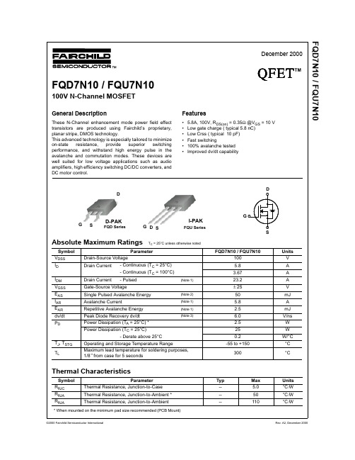
FQD7N10中文资料
VGS Top : 15.0 V
10.0 V
101
8.0 V
7.0 V
6.0 V
5.5 V
5.0 V
Bottom : 4.5 V
100 10-1
※ Notes : 1. 250μs Pulse Test 2. T = 25℃
C
100
101
V , Drain-Source Voltage [V] DS
101
100
10-1 0.2
150℃ 25℃
※ Notes : 1. VGS = 0V 2. 250μs Pulse Test
0.4 0.6 0.8 1.0 1.2 1.4 1.6 1.8 2.0 V , Source-Drain Voltage [V]
SD
Figure 4. Body Diode Forward Voltage Variation vs. Source Current and Temperature
Qg
Total Gate Charge
Qgs
Gate-Source Charge
Qgd
Gate-Drain Charge
VDD = 50 V, ID = 7.3 A, RG = 25 Ω
--
7
-- 24
-- 13
(Note 4, 5)
--
19
VDS = 80 V, ID = 7.3 A,
-- 5.8
VGS = 10 V, ID = 2.9 A = 2.9 A (Note 4) --
3.3
Dynamic Characteristics
Ciss
Input Capacitance
Coss
GENIUSMT 10-11 Gas (无锅炉) 产品规格说明说明书

Project: ________________________________ Location: ________________________________ Item #: ________________________________ Quantity: _________________________________Model: GENIUS MT 10-11 Gas (boilerless)Dimension: Width: 36 3/8 inch / 925 mm Depth: 31 3/4 inch / 805 mm Height: 44 1/8 inch / 1120 mm Weight: 366 lbs / 166 kgNumber of shelf levels : 10 x full size 18” x 26” Number of Hotel pans: 10 x full Steam pan 12” x 20” x 2”Distance/Levels :2 5/8 inch / 67 mmConnected elec. Load: 1 kW Connected gas load: 68330 BTU/hElectrical: Voltage: 110 - 130 VAC Phases: 1 phase Hz: 50 or 60 Factory recommended Amperage: 9 amp Maximum fuse rating: 15 ampGAS UNITS: SUPPLIED WITH A AWG CORD AND PLUG. DEDICATED 2 POLE CIRCUIT BREAKERREQUIRED. DO NOT CONNECT TO GFCI, USEGFEP OR HARDWIRE APPLIES TO ALL GAS UNITS.Certification:ETL, ETL Sanitation Protection (water tight): IPX 5Heat emission: - latent 6825 Btu/Hr - sensitive 5800 Btu/HrNoise level:< 70 dB (A)Cold water inlet:two (2) 3/4 inch garden hose connectionDrain:2 inch / 50 mmIT IS THE SOLE RESPONSIBILITY OF THE OWNER/ OPERATOR/PURCHASER OF THIS EQUIPMENT TO VERIFY THAT THE INCOMING WATER SUPPLY MEETS AND COMPLIES WITH THE WATER QUALITY SPECIFIED. NON-COMPLIANCE WITH THESE MINIMUM STANDARDS WILL POTENTIALLY DAMAGE THIS EQUIPMENT AND/OR COMPONENTS AND VOID THE ORIGINAL EQIPMENT MANUFACTURER’S WARRANTY.Softened water quality: - total hardness ≤ 3° dH / 3 grains/gal - pH value 7,0 - 8,5 - conductivity max. 90 µS/cm 3 - Cl: max. 240 mg/gal - SO 4: max. 400 mg/gal - SiO 4: max. 40 mg/gal - Fe: max. 0,2 mg/gal - Mn: max. 0,2 gal/l - Cu: max. 0,2 mg/gal - Cl 2: max. 0,40 mg/galWater pressure:60 PSI (35 - 87 PSI)Water flow rate: - Softened water 5,01 gal/h (at 60 PSI) - Hard water 14,50 gal/h (at 60 PSI)1. Drain2. Feet, adjustable +/- 0,4 inch (10 mm)3. Cleaner connection4. Rinsing agent connection5. Soft water connection6. Hard water connection7. Potential equalization8. Electrical cable connection9. Air filter 10. Energy optimization connection (forelectrical devices only)11. Potential-free contact (optional) (forelectrical devices only)12. Gas line connection (for gas devices only)Model: GENIUS MT 10-11 Gas (boilerless)Eloma North America 101 Corporate Woods Parkway Vernon Hills IL 60061 / USADirect: 847-215-6491 Free: 844-ELOMAUS(356-6287) Fax: 336-217-8807Standard features • MT Technology - Genuine MultiTouch display with ultrafast response and high resolution. Intuitive and preciseoperating by means of sliding, swiping or scrolling. • Quick Set - Puts all settings in the exact position with your fingertip. Changes or adds temperature and timesettings without interrupting the current cooking process on the display. • 4 Unique Start Screens manual, climaticMT, favorite, program list • 9 Menu Groups - Pasta, Desert/cakes, Bread/rolls, Poultry, Meat, Fish/seafood, Vegetables, Side dishes,Banqueting/Rethermalization • 9 modes of operation from 86°F to 572°F with an adjustable humidity between 0% to 100% - Vario-Steaming,Steaming, Forced Steaming, Combi-Steam Cooking, Convection, LT-cooking (cook & hold), Delta-T Cooking, Baking • Favorite - Customized listing for fully automatic programs. • Images - Saves individual product images. • Last 20 - Function display allows selection of the 20 most recently used cooking processes including manual andprogrammed settings for immediate restart. • Multi Cooking - automatically selects programs with the same cooking method and displays up to 15 timersinterchangeably and simultaneously on screen. • Climate Control - Patented Climatic®MT controls temperature and moisture level. Active humidification and/or de-humidification. Dry heat and humidity in combination with temperature and humidity graphically displayed. • Climatic®MT - simultaneous setting of temperature and humidity to the exact degree and percentage, temperature(°C/°F), air humidity, time, core temperature, humidity quantity, pause times • Program capacity - An integrated 9 Menu group display including a library with up to 400 recipes with 20 stepseach and 400 product pictures. • Quick Mode - An operating concept especially adapted to the needs of a multi unit operator. It allows using onlyset recipes and no manual change. • Multi Connect - Easy administration of multiple units with ProConnectMT software and advanced communicationinterfaces such as LAN or USB. • Preconfigured start time for automatic start at a freely selected time, up to 24h • Cook and Hold - Slow cooking from 86°F to 248°F. • Delta-T cooking – cooking processes regulated in accordance with the core temperature • Regeneration – storable special programs for regeneration of banquets, plates and hotel pans • Steptronic® – automatic program sequences using variable combination of cooking steps • Core temperature control for multi-point probe for precise measurement of the core temperature from 32 °F to210 °F, control of cooking procedures and explain correction in case of false core temperature probe readings. • Visual Alarm - interior lights blinking at the end of cooking program • HACCP log book – automatic internal recording and display of HACCP/LMHV data • Half Energy Feature (e/2) - Reduced electrical load. Ideal in peak times. • SPS® – Steam Protection System for prevention of burns using active steam extraction at the end of the cookingprocess • Heat Exchanger - Heat recovery through Multi-Eco System. Pre-heats incoming water for on-demand steamgeneration. Highly water and energy efficient. Exceeds drain temperature standards for most municipalities. • autoclean®MT - Patented fully-automatic technology. 100% process-controlled for guaranteed hygiene. Reducedconsumption of water and rinsing agents - quick clean in 15 minutes. Color-coded indicator of care product shows remaining quantities. No manual cool-down required. No direct employee contact with cleaning agents. Biodegradable cleaning/rinsing agents. Delayed start time possible. • 5 fan speed levels – in 5 increments or preconfigured fan timer function or pulsing, fan auto reverse for evenbrowning • Manual steam injection at any time. No pre-heating or stand-by required. Significant energy and water savings. • Steam Extraction - Steam extracted via patented Steam Protection System (SPS®) before program ends.Reduces danger of steam burns. Reduces excess humidity in the kitchen environment. Recirculation system reuses steam for maximum energy efficiency. • Active Temp – automatic preheating or cooling of the cooking chamber to set temperature • Fan-forced metal fibre burner – with combustible gas mixture in pre-chamber • High-performance triple tube heat exchanger – for highly efficient energy transfer Cleaning Alert – adjustablefrom 5-100 hours • Maintenance Alert – adjustable from 1-12 months • Safety door lock – 2-step door lock, to reduce the risk of burning due to steaming during opening the door • Integrated- self-retracting hand shower with adjustable spray functions and automatic rewind • Sensor- controlled steam cooling - for reducing the steam emission out of the exhaust air pipe • KDA service – test program for quick checksModel: GENIUS MT 10-11 Gas (boilerless)Eloma North America 101 Corporate Woods Parkway Vernon Hills IL 60061 / USADirect: 847-215-6491 Free: 844-ELOMAUS(356-6287) Fax: 336-217-8807DescriptionThe unit is a boilerless, self-cleaning, combi oven designed for steaming and convection cooking either separately, sequentially or combined. The combi oven has live-steamsystem that generates steam directly into the cooking chamber, for faster heating and re-heating without requiring a stand-by mode. An award winning Multi-Eco systemsimultaneously pre-heats incoming water and cools outgoing condensate to reduce energy and water consumption. The oven fits 10 full size sheet pans or 10 steam table pans.Construction:• Constructed to withstand temperature range from 86˚ to572°F and humidification from 0% to 100%.• Hygienic cooking chamber with coved corners, seamlesswelding. Interior and exterior housing of chrome nickel steel CrNi 18 10, BS 304 S15, AISI 304.• Tempered door glass (with hinged double panes for easycleaning) with lock-in-place positions, ventilated door, removable door gaskets & integrated drip tray.• Quick release safety door lock for single-handed operation. • Automatic fan break when door opens by contact-freemagnetic front size switch.• Integrated, external hand shower, with automatic returnand shut off - for use with door opened or closed.• Bright interior lighting with halogen lamps integrated inthe door, for easy exchange.• Exhaust and/or seal integrated in drain – fixed connectionin accordance with national and international regulations. Sensor controlled, two-stage cool down water condensation (maximum discharge temperature 176 °F). • Split water connections for hard and soft water.• Hinged control panel - easy service access from the front. • Rack can be easily removed without tools and a pan slidestop.• Manufactured according to quality management systemEN ISO 9001.• IPX 5 Water-tight rating.Options• LAN interface• External core temperature probe • Connection for energy improvement • Heat shieldSystem accessories• ProConnect programming software • Ocean version• Vario insert rack for Hotel pans only • Mobile tray racks, insert racks• SmokeFit smoker unit (WORKS ONLY FORUNITS WITHOUT CONDENSATION HOOD)Model: GENIUS MT 10-11 Gas (boilerless)Eloma North America 101 Corporate Woods Parkway Vernon Hills IL 60061 / USADirect: 847-215-6491 Free: 844-ELOMAUS(356-6287) Fax: 336-217-8807Minimum clearance for operation and maintenance workDimensionClearance [inch (mm)]Table-top devicesA Side with operating panel to the wall Minimum clearance > 2 (50) Recommended free space for maintenance / repair −B Side without operating panel to the wall Minimum clearance > 2 (50)C Rear of the combi steamer to the wall Minimum clearance > 2 (50)D Top edge of the exhaust air pipe to the ceiling Exhaust hood provided by the operating company > 2 (50) Without exhaust hood provided by the operating company> 39 3/8 (1000) Min. distanceTo Broiler, flat top, open flames , fryers without heatshield > 10 inch with heat shield > 2 1/2 inchWeight und Shipping dimensions:Shipping dimension WidthDepthHeight41 2/3 inch/ 1060 mm 42 1/8 inch/ 1070 mm 52 1/3 inch/ 1330 mmFreight class class 150Cubing packingone unit per palletWeightMax. load per shelf: 33 lbs / 15 kg Max. load size: 110 lbs / 50 kg Net load device: 366 lbs / 166 kg Shipping load device:403 lbs / 183 kgModel: GENIUS MT 10-11 Gas (boilerless)Eloma North America 101 Corporate Woods Parkway Vernon Hills IL 60061 / USADirect: 847-215-6491 Free: 844-ELOMAUS(356-6287) Fax: 336-217-8807Please note:Based on the water quality in your area, a water filtration system is required. Any filter applied should be sized to handle the flow rate of the device selected, as well as achieve the water quality specified.。
FUJITSU CELSIUS H770移动工作站数据册说明书
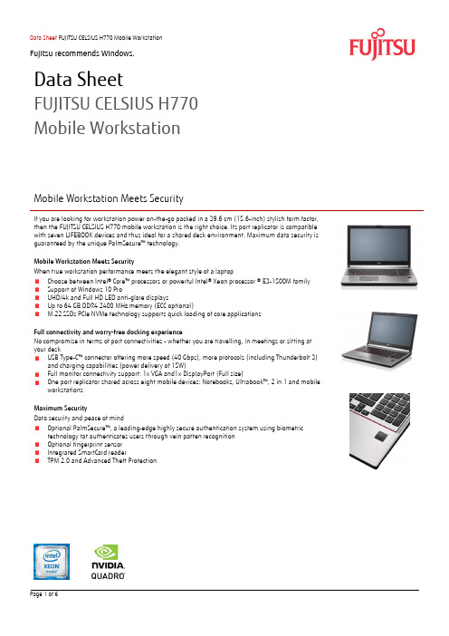
Data SheetFUJITSU CELSIUS H770Mobile WorkstationMobile Workstation Meets SecurityIf you are looking for workstation power on-the-go packed in a 39.6 cm (15.6-inch) stylish form factor,then the FUJITSU CELSIUS H770 mobile workstation is the right choice. Its port replicator is compatible with seven LIFEBOOK devices and thus ideal for a shared desk environment. Maximum data security is guaranteed by the unique PalmSecure™ technology.Mobile Workstation Meets SecurityWhen true workstation performance meets the elegant style of a laptopChoose between Intel® Core™ processors or powerful Intel® Xeon processor ® E3-1500M familySupport of Windows 10 ProUHD/4k and Full HD LED anti-glare displaysUp to 64 GB DDR4 2400 MHz memory (ECC optional)M.22 SSDs PCIe NVMe technology supports quick loading of core applicationsFull connectivity and worry-free docking experienceNo compromise in terms of port connectivities - whether you are travelling, in meetings or sitting at your deskUSB Type-C™ connector offering more speed (40 Gbps), more protocols (including Thunderbolt 3)and charging capabilities (power delivery of 15W)Full monitor connectivity support: 1x VGA and1x DisplayPort (Full size)One port replicator shared across eight mobile devices: Notebooks, Ultrabook™, 2 in 1 and mobileworkstationsMaximum SecurityData security and peace of mindOptional PalmSecure™, a l eading-edge highly secure authentication system using biometrictechnology tat authenticates users through vein patten recognitionOptional fingerprint sensorIntegrated SmartCard readerTPM 2.0 and Advanced Theft ProtectionCOMPONENTSBase Unit CELSIUS H770Operating System Windows 10 ProProcessor Intel® Xeon® processor E3-1505M v6 (3.0 GHz, up to 4.0 GHz, 8 MB, Intel® HD Graphics P630)Intel® Core™ i7-7820HQ processor (2.9 GHz, up to 3.9 GHz, 8 GB, Intel® HD Graphics 630)Memory modules 8GB (2x 4GB) DDR4 2400Mhz16GB (2x 8GB) DDR4 2400Mhz16GB (2x 8GB) DDR4 2400Mhz, ECC32GB (2x 16GB) DDR4 2400Mhz32GB (2x 16GB) DDR4 2400Mhz, ECCHard disk drives (internal) SSHD SATA III, 5400 rpm, 500 GBSSHD SATA III, 5400 rpm, 1 TBSSD SATA III, 512 GBSSD SATA III, 512 GB, SEDSSD SATA III, 1 TB, SEDPCIe-SSD, 512GB, SEDPCIe-SSD, 1 TB, SEDHard disk notes One Gigabyte equals one billion bytes, when referring to hard disk drive capacity.Accessible capacity may vary, also depending on used software.Up to 20 GB of HDD space is reserved for system recoveryInternal HDD interface: S-ATA III (6GBit/s)Modular Bay Options 2nd bay batteryDVD Super MultiWeight SaverInterface add on cards/components (optional)4G/LTE (Optional) LTE Sierra Wireless EM7305 (Downlink speed up to 100 Mbit/s, Uplink speed up to 50 Mbit/s)WLAN (Optional) Intel® Dual Band Wireless-AC 8265 802.11ac/a/b/g/n (2x2) and Bluetooth® 4.2 ComboDisplay 39.6 cm (15.6-inch), LED backlight, (Full HD), Anti-Glare, WVA, 1,920 x 1,080 pixel, 700:1, 300 cd/m²39.6 cm (15.6-inch), LED backlight, (4K UHD), Anti-glare, WVA, 3,840 x 2,160 pixel, 700:1, 300 cd/m² MultimediaCamera (Optional) Built-in webcam, 2.0 megapixelMicrophone 2x digitalBase unitBase unit CELSIUS H770General system informationChipset Intel® QM175 or CM238 (depending on CPU)Supported capacity RAM (min.) 8 GBSupported capacity RAM (max.) 64 GBMemory slots total 4 DIMM (DDR4)Memory notes Memory Slots are depending on processor type. 2 DIMM slots with dual core processors, 4 DIMM slots withquad core processorLAN Built-in 10/100/1000 MBit/s, Intel® I219LMBIOS features InsydeH20 BiosAudio type On boardAudio codec Realtek ALC255 with MaxxAudioAudio features Stereo Speakers, 2 digital microphonesDisplayDisplay notes ISO 9241-307 - Pixel class II[Full HD] Viewing angle: Left/Right 85°, Top 85°, Bottom 85°; Color Gamut: 72%[4K UHD] Viewing angle: Left/Right 85°, Top 85°, Bottom 85°; Color Gamut: 72%GraphicsGraphics card NVIDIA® Quadro® M1200M 4GB GDDR5: 640 CUDA CoresNVIDIA® Quadro® M2200M 4GB GDDR5: 1024 CUDA CoresGraphics features DualView3 Display Support (2 external, 1 internal)5 Display Support w/ Port Replicator (4 external, 1 internal)Max. resolution (DisplayPort) Up to 4,096 x 2,160Max. resolution (USB Type-C DP) Up to 4,096 x 2,160Max. resolution (D-SUB) Up to 1,920 x 1,200Max. resolutionUp to 4,096 x 2,160(DisplayPort 1,2 on Port Replicator)Up to 1,920 x 1,200Max. resololution(DVI on Port Replicator)Max. resolutionUp to 1,920 x 1,200(D-SUB on Port Replicator)InterfacesDC-in 1Audio: line-in / microphone 1Audio: line-out / headphone 1Internal microphones 2 digital microphones (array)USB 2.0 total 1USB 3.1 Gen1 total 2USB 3.1 Type-C 1 (USB 3.1 Gen2 (10 Gbps), Thunderbolt 3 (20/40Gbps), Power Delivery (15W), DP 1.2)VGA 1DisplayPort 1Ethernet (RJ-45) 1Memory card slots 1 (SD/SDHC) SD/microSD = 2GB, SDHC/micro SDHC = 32GB, SDXC = 64GBSmartCard slot 1SIM card slot 1 (only for models with integrated 4G/LTE module)Kensington Lock Support 1Port Replicator interfaces (optional)DC-in 1 (19V)Power on switch 1Audio: headphone 1Audio: microphone 1USB 3.0 total 4DisplayPort 2 - 1 DP (next to DVI) is shared with DVI, works when DVI not connectedVGA 1DVI 1 - shared with DP (next to DVI) - works when DP (next to DVI) not connectedEthernet (RJ-45) 1 (10/100/1000)Kensington Lock support 1 (Port rep & System)eSATA 1Notes Port replicator supports 0-Watts functionalityKeyboard and pointing devicesUS Keyboard w/o BacklightNumber of keyboard keys: 104 (w/10 keys), Keyboard pitch: 18.4 mm, Keyboard stroke: 1.7 mmTouchpad with three mouse buttonsECO ButtonStatus LEDPower ButtonWireless technologiesAntennas 2 Dual band WLAN antennas, 2 UMTS/LTE antennas optional, 1 Bluetooth antenna shared with WLAN Bluetooth Bluetooth® 4.1 (Win10)WLAN encryption WEP, WPA, WPA2WLAN notes Import and usage according to country-specific regulations.WiDi support Yes (with Intel W-LAN)Power supplyAC Adapter 19 V / 150 W (7.89 A), 100 V - 240 V, 50 Hz - 60 Hz, 3-pin (grounded) AC AdapterBattery 1st Battery: Li-Ion battery 6-cell, 72 Wh2nd Bay Battery: Li-Ion battery 6-cell, 28 Wh1st Battery Run-time Up to 11hrs (MobileMark® 2014)1st and 2nd Battery Run-time Up to 14hrs (MobileMark® 2014)Battery notes Battery runtime information is based on worldwide acknowledged BAPCo® MobileMark® 2014 (officeproductivity). Refer to for additional details.The BAPCo® MobileMark® Benchmark provides results that enable direct product comparisons betweenmanufacturers. It does not guarantee any specific battery runtime which actually can be lower and may varydepending on product model, configuration, application and power management settings. The batterycapacity decreases slightly with every re-charge and over its lifetime.Dimensions / Weight / EnvironmentalDimensions (W x D x H) 380.0 x 257.0 x 24.8-31.9 mm (w/o bump)Weight Start from 2.75 kg (6.1 lbs)Weight notes Actual weight may vary depending on configurationOperating ambient temperature 5 - 35 °C (41 - 95 °F)Operating relative humidity 20 - 80 % (relative humidity, non-condensing)ComplianceGlobal RoHS (EU & China)Medical EMC standard IEC60601-1-2 in combination with medical kitENERGY STAR® 6.1EPEAT® Gold (dedicated regions)Additional SoftwareAdditional Software (preinstalled)Fujitsu Anytime USB Charge UtilityFujitsu Battery UtilityFujitsu Bonus AppsFujitsu Function ManagerFujitsu LIFEBOOK Application PanelFujitsu Mic Mute UtilityFujitsu Mobility Center Extension UtilityFujitsu Software AutoInstallerFujitsu Workplace ProtectMicrosoft® Office 2016 TrialMcAfee Multi Access 60 days TrialAdditional Software (optional) Sierra Wireless Skylight (optional with WWAN)CyberLink PowerDVD (optional with DVD Super Multi)Recovery DVD for Windows®ManageabilityManageability technology PXE 2.1 Boot codeWake up from S5 (off mode)WoL (Wake on LAN)Intel® vPro™ technology (depending on CPU)iAMT 11.0 (depending on CPU)Supported standards WMI, PXESecurityPhysical Security Kensington Lock supportSystem and BIOS Security Optional: Discrete Trusted Platform Module (TPM 2.0)Optional: Fujitsu EraseDiskUser Security Hard disk passwordUser and supervisor BIOS passwordEmbedded fingerprint sensor (optional)Embedded palm vein sensor (optional)Smartcard reader (integrated)Fujitsu Workplace Protect (secure authentication solution)WarrantyStandard warranty 3 years (depending on country)Service level Bring-in Service (depending on country specific requirements)Maintenance and Support ServicesRecommended service 3 years, 9x5, Response Time: Next Business DaySpare Parts availability 5 years after end of product lifeRecommended AccessoriesClassic Port Replicator Flexibility, expandability, desktop replacement and investment protection are just a few benefits ofFujitsu docking options. It takes just a second to attach your notebook to the Port Replicator andget connected to your external display, keyboard and mouse. Your workplace is simple and tidywhile you are instantly ready to work with your notebook.Compatible Models: LIFEBOOK U745, T7, E5, E7, CELSIUS H730, H760Fujitsu Prestige Backpack The FUJITSU Prestige Backpack 17 protects notebooks with up to 17-inch displays. It contains threelarge compartments, two elastic mesh side pockets and a front bay. The padded backcompartment provides protection for your notebook, while other sections store power adaptors andoffice supplies. Padded shoulder straps and back cushions provide comfort on the move.Fujitsu Display P24-8 WS Pro The FUJITSU P24-8 WS Pro display (24-inch, 16:10) provides outstanding picture performancethanks to cutting edge panel technology. It is the perfect choice for CAD and documentmanagement applications with request for 1,200 lines. It also boasts unique and innovativefeatures such as our patent-applied Presence Sensor technology and USB support during standby.More informationIn addition to Fujitsu CELSIUS H770, Fujitsu provides a range of platform solutions. They combine reliable Fujitsu products with the best in services, know-how and worldwide partnerships.Dynamic InfrastructuresWith the Fujitsu Dynamic Infrastructures approach, Fujitsu offers a full portfolio of IT products, solutions and services, ranging from clients to data centre solutions, Managed Infrastructure and Infrastructure-as-a-Service. How much you benefit from Fujitsu technologies and services depends on the level of cooperation you choose. This takes IT flexibility and efficiency to the next level.Computing Products/global/services/computing To learn more about Fujitsu CELSIUS H770,please contact your Fujitsu salesrepresentative, Fujitsu Business partner, orvisit our website./pcAll rights reserved, including intellectualproperty rights. Technical data subject tomodifications and delivery subject toavailability. Any liability that the data andillustrations are complete, actual or correct isexcluded. Designations may be trademarksand/or copyrights of the respectivemanufacturer, the use of which by third partiesfor their own purposes may infringe the rightsof such owner.Fujitsu Green Policy Innovation is ourworldwide project for reducing burdens on theenvironment.Using our global know-how, we aim tocontribute to the creation of a sustainableenvironment for future generations throughIT.Please find further information at http://www./global/about/environment/Technical data are subject to modification anddelivery subject to availability. Any liabilitythat the data and illustrations are complete,actual or correct is excluded. Designations maybe trademarks and/or copyrights of therespective manufacturer, the use of which bythird parties for their own purposes mayinfringe the rights of such owner.HONG KONGFujitsu PC Asia Pacific LtdTel: (852) 3910-8228Email:***********************.com /pc SINGAPOREFujitsu Asia Pte Ltd.Tel: (65) 6710-5403Email:**********************.com/pcCHINAFujitsu (China) Co., Ltd.Tel:(86*************Email:*************************.com/pcINDONESIAPt. Fujitsu IndonesiaTel: (62) 21-570-9330Email:*********************.com/pcPHILIPPINESFujitsu Philippines, Inc. Tel: (63) 2-812-4001 Email:***************.com /pc MALAYSIAFujitsu (Malaysia) Sdn. BhdTel: (60) 3-8318-3700Email:********************.com/pcTAIWANFujitsu Taiwan Ltd.Tel: (886) 0800-688-028Email:*******************.com/pcTHAILANDFujitsu (Thailand) Co., LtdTel: (66) 0-2302-1500Email:***************.com/pcVIETNAMFujitsu Vietnam Limited (Hanoi)Tel: (84) 4-2220-3113Email:****************.com/pcNote: For countries not listed above, please contact our Hong Kong office.Ultrabook, Celeron, Celeron Inside, Core Inside, Intel, Intel Logo, Intel Atom, Intel Atom Inside, Intel Core, Intel Inside, Intel Inside Logo, Intel vPro, Itanium,Itanium Inside, Pentium, Pentium Inside, vPro Inside, Xeon, and Xeon Inside are trademarks of Intel Corporation in the U.S. and/or other countries.All rights to the mentioned trademarks reside with their respective owners. Fujitsu endeavours to ensure that the information in this documentation is correct and fairly stated, but does not accept liability for any errors or omissions. The development of Fujitsu products and services is continuous and published information may not be up to date. It is important to check the current position with Fujitsu. The document is not part of the contract or licence save in so far as may be expressly agreed.Last Update: 6th July 2017。
EGP10G;中文规格书,Datasheet资料

EGP10A - EGP10K 1.0 Ampere Glass Passivated High Efficiency Rectifiers July 2007EGP10A - EGP10K 1.0 Ampere Glass Passivated High Efficiency RectifiersTypical Performance CharacteristicsEGP10A - EGP10K 1.0 Ampere Glass Passivated High Efficiency RectifiersReverse Recovery Time Characterstic and Test Circuit DiagramTRADEMARKSThe following are registered and unregistered trademarks and service marks Fairchild Semiconductor owns or is authorized to use and is not intended to be an exhaustive list of all such trademarks.DISCLAIMERFAIRCHILD SEMICONDUCTOR RESERVES THE RIGHT TO MAKE CHANGES WITHOUT FURTHER NOTICE TO ANY PRODUCTS HEREIN TO IMPROVE RELIABILITY, FUNCTION, OR DESIGN. FAIRCHILD DOES NOT ASSUME ANY LIABILITY ARISING OUT OF THE APPLICATION OR USE OF ANY PRODUCT OR CIRCUIT DESCRIBED HEREIN; NEITHER DOES IT CONVEY ANY LICENSE UNDER ITS PATENT RIGHTS, NOR THE RIGHTS OF OTHERS. THESE SPECIFICATIONS DO NOT EXPAND THE TERMS OF FAIRCHILD’S WORLDWIDE TERMS AND CONDITIONS, SPECIFICALLY THE WARRANTY THEREIN, WHICH COVERS THESE PRODUCTS.LIFE SUPPORT POLICYFAIRCHILD’S PRODUCTS ARE NOT AUTHORIZED FOR USE AS CRITICAL COMPONENTS IN LIFE SUPPORT DEVICES OR SYSTEMS WITHOUT THE EXPRESS WRITTEN APPROVAL OF FAIRCHILD SEMICONDUCTOR CORPORATION.As used herein:1. Life support devices or systems are devices or systemswhich, (a) are intended for surgical implant into the body, or(b) support or sustain life, and (c) whose failure to performwhen properly used in accordance with instructions for useprovided in the labeling, can be reasonably expected to resultin significant injury to the user.2. A critical component is any component of a life supportdevice or system whose failure to perform can be reasonablyexpected to cause the failure of the life support device orsystem, or to affect its safety or effectiveness.PRODUCT STATUS DEFINITIONSDefinition of TermsACEx®Build it Now™CorePLUS™CROSSVOLT™CTL™Current Transfer Logic™EcoSPARK®Fairchild®Fairchild Semiconductor®FACT Quiet Series™FACT®FAST®FastvCore™FPS™FRFET®Global Power Resource SMGreen FPS™Green FPS™ e-Series™GTO™i-Lo™IntelliMAX™ISOPLANAR™MegaBuck™MICROCOUPLER™MicroFET™MicroPak™Motion-SPM™OPTOLOGIC®OPTOPLANAR®®PDP-SPM™Power220®Power247®POWEREDGE®Power-SPM™PowerTrench®Programmable Active Droop™QFET®QS™QT Optoelectronics™Quiet Series™RapidConfigure™SMART START™SPM®STEALTH™SuperFET™SuperSOT™-3SuperSOT™-6SuperSOT™-8SyncFET™The Power Franchise®TinyBoost™TinyBuck™TinyLogic®TINYOPTO™TinyPower™TinyPWM™TinyWire™µSerDes™UHC®UniFET™VCX™Datasheet Identification Product Status DefinitionAdvance Information Formative or In DesignThis datasheet contains the design specifications for product development.Specifications may change in any manner without notice.Preliminary First ProductionThis datasheet contains preliminary data; supplementary data will be pub-lished at a later date. Fairchild Semiconductor reserves the right to makechanges at any time without notice to improve design.No Identification Needed Full ProductionThis datasheet contains final specifications. Fairchild Semiconductor reservesthe right to make changes at any time without notice to improve design. Obsolete Not In ProductionThis datasheet contains specifications on a product that has been discontin-ued by Fairchild semiconductor. The datasheet is printed for reference infor-mation only.Rev. I30分销商库存信息: FAIRCHILDEGP10G。
CWSB11AA2F;CWSB21AA1F;CWSB21AA2F;CWSA11AANS;CWSA11AAN1S;中文规格书,Datasheet资料
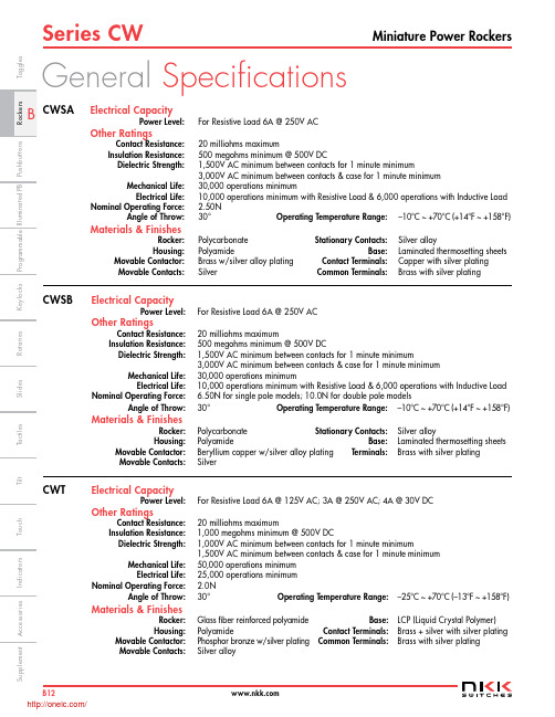
Series CWMiniature Power RockersB12I n d i c a t o r sA c c e s s o r i e sS u p p l e m e n tT a c t i l e sK e y l o c k sR o t a r i e sP u s h b u t t o n sI l l u m i n a t e d P BS l i d e s P r o g r a m m a b l eT o u c hT i l tT o g g l e sGeneral SpecificationsElectrical CapacityPower Level: For Resistive Load 6A @ 250V ACOther RatingsContact Resistance: 20 milliohms maximumInsulation Resistance: 500 megohms minimum @ 500V DCDielectric Strength: 1,500V AC minimum between contacts for 1 minute minimum3,000V AC minimum between contacts & case for 1 minute minimum Mechanical Life: 30,000 operations minimumElectrical Life: 10,000 operations minimum with Resistive Load & 6,000 operations with Inductive Load N ominal Operating Force: 2.50N Angle of Throw: 30° Operating Temperature Range: –10°C ~ +70°C (+14°F ~ +158°F)Materials & FinishesRocker: Polycarbonate Stationary Contacts:Silver alloyHousing:PolyamideBase:Laminated thermosetting sheets Movable Contactor: Brass w/silver alloy plating Contact Terminals: Copper with silver platingMovable Contacts:SilverCommon Terminals:Brass with silver platingElectrical CapacityPower Level: For Resistive Load 6A @ 250V ACOther RatingsContact Resistance:20 milliohms maximumInsulation Resistance: 500 megohms minimum @ 500V DCDielectric Strength: 1,500V AC minimum between contacts for 1 minute minimum3,000V AC minimum between contacts & case for 1 minute minimum Mechanical Life: 30,000 operations minimumElectrical Life: 10,000 operations minimum with Resistive Load & 6,000 operations with Inductive Load N ominal Operating Force: 6.50N for single pole models; 10.0N for double pole models Angle of Throw: 30° Operating Temperature Range: –10°C ~ +70°C (+14°F ~ +158°F)Materials & FinishesRocker: Polycarbonate Stationary Contacts: Silver alloy Housing:Polyamide Base: Laminated thermosetting sheets Movable Contactor: Beryllium copper w/silver alloy plating Terminals: Brass with silver platingMovable Contacts:SilverElectrical CapacityPower Level: For Resistive Load 6A @ 125V AC; 3A @ 250V AC; 4A @ 30V DCOther RatingsContact Resistance:20 milliohms maximumInsulation Resistance: 1,000 megohms minimum @ 500V DCDielectric Strength: 1,000V AC minimum between contacts for 1 minute minimum1,500V AC minimum between contacts & case for 1 minute minimum Mechanical Life: 50,000 operations minimum Electrical Life: 25,000 operations minimum N ominal Operating Force: 2.0N Angle of Throw:30° Operating Temperature Range: –25°C ~ +70°C (–13°F ~ +158°F)Materials & FinishesRocker: Glass fiber reinforced polyamide Base: LCP (Liquid Crystal Polymer) Housing:Polyamide Contact Terminals: Brass + silver with silver plating Movable Contactor: Phosphor bronze w/silver plating Common Terminals: Brass with silver platingMovable Contacts:Silver alloyCWSB CWT CWSA/Series CWMiniature Power Rockers B13I n d i c a t o r s A c c e s s o r i e s S u p p l e m e n t T a c t i l e s K e y l o c k s R o t a r i e s P u s h b u t t o n s I l l u m i n a t e d P B S l i d e s P r o g r a m m a b l e T o g g l esT o u c h T i lt Distinctive CharacteristicsCWSALow cost molded rocker.See-saw contact mechanismStable stationary contact construction for high reliability.Easily installed with snap-in mounting.Large terminal hole dimensioned .067” x .098” (1.7mm x 2.5mm) simplifies wiring and soldering.Wave Soldering (PC version): See Profile A in Supplement section. Manual Soldering: See Profile A in Supplement section.CWSBLow cost molded rocker.Snap-acting contact mechanism gives smooth actuation and audible feedback.Stable stationary contact construction for high reliability.Front panel, snap-in mounting for labor-saving installation.Solder lug/quick connect terminals can be used with connectors.Manual Soldering: See Profile B in Supplement section.CWTLow cost molded rocker in compact, slim design.See-saw contact mechanismOutstanding insulation resistance and dielectric strength.Dust proof construction protects contact area.Stable stationary contact construction for high reliability.Front panel, snap-in mounting for labor-saving installation.Terminals are molded in and epoxy sealed to lock out flux, dust, and other contaminants.Manual Soldering: See Profile A in Supplement section./Series CWMiniature Power RockersB14I n d i c a t o r sA c c e s s o r i e s S u p p l e m e n tT a c t i l e sK e y l o c k sR o t a r i e sP u s h b u t t o n sI l l u m i n a t e d P B S l i d e sP r o g r a m m a b l eT o u c h T i l t T o g g l e sSTANDARDS & CERTIFICATIONSCWSASpecific CWSA models listed below are qualified for Underwriters Laboratories Inc. recognition and Canadian Standards Association certification. cULus marking on case is standard as noted in following table.Model Ratings @ AC cULus File No. Marking on CaseCWSA11 6A @ 250V E44145 StandardCWSA126A @ 250VE44145StandardCWSBSpecific CWSB models listed below are qualified for Underwriters Laboratories Inc. recognition and Canadian Standards Association certification. cULus marking on case is standard as noted in following table.Model Ratings @ AC cULus File No. Marking on CaseCWSB11 6A @ 250V E44145 StandardCWSB216A @ 250VE44145StandardCWTSpecific CWT model listed below is qualified for Underwriters Laboratories Inc. recognition and Canadian Standards Association certification. cULus marking on case is standard as noted in following table.Model Ratings @ AC cULus File No. Marking on CaseCWT126A @ 125V E44145Standard3A @ 250V/Series CWMiniature Power RockersB15I n d i c a t o r sA c c e s s o r i e s S u p p l e m e n t T a c t i l e s K e y l o c k s R o t a r i e s P u s h b u t t o n s I l l u m i n a t e d P BS l i d e s P r o g r a m m a b l e T o g g l esT o u c hT i ltTYPICAL ORDERING EXAMPLECWSA11AANSTYPICAL SWITCH ORDERING EXAMPLESFor SPST & SPDTNo CodeNoneFor SPST 1Horizontal 2Vertical 3Dot MarkingTYPICAL ORDERING EXAMPLECWSB21AA2FCWT12AAS1* Wire harness & cable assemblies offered only in Americas* Wire harness & cable assemblies offered only in Americas* Wire harness & cable assemblies offered only in Americas/Series CWMiniature Power RockersB16I n d i c a t o r s A c c e s s o r i e sS u p p l e m e n tT a c t i l e sK e y l o c k sR o t a r i e s P u s h b u t t o n sI l l u m i n a t e d P B S l i d e sP r o g r a m m a b l eT o u c hT i l t T o g g l e sTYPICAL SWITCH DIMENSIONS FOR CWSACWSA12AANSRight Angle Single Pole • Horizontal On-Off InscriptionSolder LugSingle Pole • No InscriptionCWSA11AAN1HINSCRIPTIONSNoneNot available in double pole.No CodeHorizontal OrientationOnly On-None-Off models are available with the horizontal inscription.1Vertical OrientationOnly On-None-Off models are available with the vertical inscription.2Dot MarkingOnly Single Pole On-None-Off models are available with the dot inscription.3The IEC symbols for On-Off are supplied with Single Throw models only. Orientation of inscription must be selected.Inscription color is white ink on black.Panel Thickness .030” ~ .079” (0.75mm ~ 2.0mm)Terminal numbers are on side of switch body Terminal numbers areon side of switch bodySingle throw model doesnot have terminal 1b /Series CWMiniature Power RockersB17I n d i c a t o r s A c c e s s o r i e s S u p p l e m e n tT a c t i l e sK e y l o c k sR o t a r i e sP u s h b u t t o n sI l l u m i n a t e d P B S l i d e sP r o g r a m m a b l e T o g g l esT o u c hT i l tCWT12AAS1Single Pole • No InscriptionSolder LugTYPICAL SWITCH DIMENSIONS FOR CWSBCWSB21AA2FSingle Pole • Dot Inscription Right AngleDouble Pole • Vertical On-Off InscriptionQuick ConnectCWSB11AA3HFootprint DPSTPanel Thickness .030” ~ .079” (0.75mm ~ 2.0mm)TYPICAL SWITCH DIMENSIONS FOR CWTPanel Thickness .030” ~ .079” (0.75mm ~ 2.0mm)FootprintSPSTTerminal numbers are on bottom of switchTerminal numbers are on bottom of switchTerminal numbers are on side of switch body /分销商库存信息:NKK-SWITCHCWSB11AA2F CWSB21AA1F CWSB21AA2F CWSA11AANS CWSA11AAN1S CWSA11AAN2S CWSA11AAN3S CWSB11AAF CWSA12AANS CWT12AAS1CWSA11AAN1H CWSB11AA1F CWSB11AA3F CWT12AAS1/U CWSA12AANH CWSA11AANH CWSB11AAH CWSA11AAN2H CWSB11AA1H CWT12AAS1/UC CWSB11AA3H CWSB21AA1H CWSB21AA2H。
- 1、下载文档前请自行甄别文档内容的完整性,平台不提供额外的编辑、内容补充、找答案等附加服务。
- 2、"仅部分预览"的文档,不可在线预览部分如存在完整性等问题,可反馈申请退款(可完整预览的文档不适用该条件!)。
- 3、如文档侵犯您的权益,请联系客服反馈,我们会尽快为您处理(人工客服工作时间:9:00-18:30)。
Description
The Hyper Red source color devices are made with AlGaInP on GaAs substrate Light Emitting Diode.
Package Dimensions
Notes: 1. All dimensions are in millimeters (inches). 2. Tolerance is ±0.25(0.01") unless otherwise noted. 3. Lead spacing is measured where the leads emerge from the package. 4. The specifications, characteristics and technical data described in the datasheet are subject to change without prior notice.
Notes: 1.Wavelength: +/-1nm. 2. Forward Voltage: +/-0.1V.
Absolute Maximum Ratings at TA=25°C
Parameter Power dissipation DC Forward Current Peak Forward Current [1] Reverse Voltage Operating/Storage Temperature Lead Solder Temperature [2] Lead SolderP710A10SURC/E
SPEC NO: DSAL0555 APPROVED: WYNEC
REV NO: V.2 CHECKED: Allen Liu
DATE: MAR/07/2011 DRAWN: J.Yu
PAGE: 3 OF 6 ERP: 1101029222
/
T-1 (3mm) SOLID STATE LAMP
Part Number: WP710A10SURC/E Hyper Red
Features
z Low power consumption. z Popular T-1 diameter package. z General purpose leads. z Reliable and rugged. z Long life - solid state reliability. z Available on tape and reel. z RoHS compliant.
SPEC NO: DSAL0555 APPROVED: WYNEC
REV NO: V.2 CHECKED: Allen Liu
DATE: MAR/07/2011 DRAWN: J.Yu
PAGE: 6 OF 6 ERP: 1101029222
/
分销商库存信息:
KINGBRIGHT WP710A10SURC/E
Units mW mA mA V
SPEC NO: DSAL0555 APPROVED: WYNEC
REV NO: V.2 CHECKED: Allen Liu
DATE: MAR/07/2011 DRAWN: J.Yu
PAGE: 2 OF 6 ERP: 1101029222
/
Part No. Dice Lens Type Iv (mcd) [2] @ 20mA Min. WP710A10SURC/E Hyper Red (AlGaInP) WATER CLEAR 1600 Typ. 2500 Viewing Angle [1] 2θ1/2 34°
Notes: 1. θ1/2 is the angle from optical centerline where the luminous intensity is 1/2 of the optical peak value. 2. Luminous intensity/ luminous Flux: +/-15%.
SPEC NO: DSAL0555 APPROVED: WYNEC
REV NO: V.2 CHECKED: Allen Liu
DATE: MAR/07/2011 DRAWN: J.Yu
PAGE: 1 OF 6 ERP: 1101029222
/
Selection Guide
/
SPEC NO: DSAL0555 APPROVED: WYNEC
REV NO: V.2 CHECKED: Allen Liu
DATE: MAR/07/2011 DRAWN: J.Yu
PAGE: 5 OF 6 ERP: 1101029222
/
Electrical / Optical Characteristics at TA=25°C
Symbol λpeak λD [1] Δλ1/2 C VF [2] IR Parameter Peak Wavelength Dominant Wavelength Spectral Line Half-width Capacitance Forward Voltage Reverse Current Device Hyper Red Hyper Red Hyper Red Hyper Red Hyper Red Hyper Red Typ. 640 630 25 45 1.9 2.5 10 Max. Units nm nm nm pF V uA Test Conditions IF=20mA IF=20mA IF=20mA VF=0V;f=1MHz IF=20mA VR = 5V
Notes: 1. 1/10 Duty Cycle, 0.1ms Pulse Width. 2. 2mm below package base. 3. 5mm below package base.
Hyper Red 75 30 200 5 -40°C To +85°C 260°C For 3 Seconds 260°C For 5 Seconds
PACKING & LABEL SPECIFICATIONS
WP710A10SURC/E
WP710A10xxx
SPEC NO: DSAL0555 APPROVED: WYNEC
REV NO: V.2 CHECKED: Allen Liu
DATE: MAR/07/2011 DRAWN: J.Yu
PAGE: 4 OF 6 ERP: 1101029222