MIC5013YM;MIC5013YN;MIC5013YM TR;MIC5013BM;MIC5013BN;中文规格书,Datasheet资料
500系列话筒前置放大器502快速入门指南说明书

500 SERIES MICROPHONE PREAMPLIFIER 502 500 Series Modular Midas Microphone Preamplifier with Classic XL4 FiltersV 1.0带有此标志的终端设备具有强大的电流, 存在触电危险。
仅限使用带有 1/4'' TS 或扭锁式插头的高品质专业扬声器线。
所有的安装或调整均须由合格的专业人员进行。
此标志提醒您,产品内存在未绝缘的危险电压, 有 触电危险。
此标志提醒您查阅所附的重要的使用及维修说明。
请阅读有关手册。
小心为避免触电危险, 请勿打开机顶盖 (或背面挡板)。
设备内没有可供用户维修使用的部件。
请将维修事项交由合格的专业人员进行。
小心为避免着火或触电危险, 请勿将此设备置于雨淋或潮湿中。
此设备也不可受液体滴溅, 盛有液体的容器也不可置于其上, 如花瓶等。
小心维修说明仅是给合格的专业维修人员使用的。
为 避免触电危险, 除了使用说明书提到的以外, 请勿进行任何其它维修。
所有维修均须由合格的专业人员进行。
1. 请阅读这些说明。
2. 请妥善保存这些说明。
3. 请注意所有的警示。
4. 请遵守所有的说明。
5. 请勿在靠近水的地方使用本产品。
6. 请用干布清洁本产品。
7. 请勿堵塞通风口。
安装本产品时请遵照厂家的说明。
8. 请勿将本产品安装在热源附近, 如 暖气片, 炉子或其它产生热量的设备 ( 包括功放器)。
9. 请勿移除极性插头或接地插头的安全装置。
接地插头是由两个插塞接点及一个接地头构成。
若随货提供的插头不适合您的插座, 请找电工更换一个合适的插座。
10. 妥善保护电源线, 使其不被践踏或刺破, 尤其注意电源插头、多用途插座及设备连接处。
11. 请只使用厂家指定的附属设备和配 件。
12. 请只使用厂家指定的或随货销售的手推车, 架子, 三 角架, 支架和桌子。
若使用手推车来搬运设备, 请注意安全放置设备, 以 避免手推车和设备倾倒而受伤。
马兰士 SR5013 环绕声接收器 操作说明书

AV Surround ReceiverSR5013操作说明书附件9安装电池10遥控器的操作范围10特点11高音效11高性能12简易操作16部件名称与功能17前面板17显示屏20后面板22遥控器26连接方法扬声器安装30连接扬声器37连接扬声器之前37扬声器配置和“放大器分配”设置41连接5.1声道扬声器42连接7.1声道扬声器43连接5.1声道扬声器:前置扬声器的双功放连接49连接5.1声道扬声器:第二对前置扬声器50连接多区域扬声器51连接电视机53连接1:配备了HDMI端子并兼容ARC(Audio Return Channel)的电视机54连接2:配备了HDMI端子且不兼容ARC(Audio Return Channel)的电视机55连接3 : 未配备HDMI端子的电视机56连接播放设备57连接机顶盒(卫星调谐器/有线电视)58连接DVD播放机或蓝光碟片播放机59连接摄像机或游戏机60连接电唱机61使用多声道输出端子连接设备62将USB存储设备连接至USB端口63连接FM/AM天线64连接至家庭网络(LAN)66有线LAN66无线局域网67连接外部控制设备68 REMOTE CONTROL插孔68直流输出(DC OUT)插孔69连接电源线70播放基本操作72开启电源72选择输入源72调节音量73暂时关闭声音(静音)73播放DVD播放机/蓝光碟片播放机73播放USB存储设备74播放储存在USB存储设备上的文件75在蓝牙设备上收听音乐78从蓝牙设备播放音乐79与其他蓝牙设备配对80从蓝牙设备重新连接至本机81收听FM/AM广播82收听FM/AM广播83通过输入频率来进行调谐(直接调谐)84更改调谐模式(调谐模式)85自动调谐到电台并进行预设(自动预设记忆)85预设当前广播电台(预设记忆)86收听预设电台86指定预设广播电台的名称(预设名称)87跳过预设的广播电台(跳过预设)88取消跳过预设89收听网络电台90收听网络电台91播放存储在计算机或NAS中的文件92播放存储在计算机或NAS中的文件93获取 HEOS App96 HEOS账户97从流媒体音乐服务播放98在多个房间聆听相同的音乐101AirPlay功能105从iPhone、iPod touch或iPad播放歌曲106从iTunes播放歌曲106使用本机的遥控器进行iTunes的播放操作107在多个同步设备上播放iPhone、iPod touch或 iPad上的曲目 (AirPlay 2)108 QPlay功能109在本机上播放QQ音乐曲目109便捷功能110添加到HEOS最爱收藏111播放HEOS最爱收藏111删除HEOS最爱收藏112调节各声道的音量以与输入源相符(声道电平调节)113调节音调(音调)114音频播放过程中播放所需视频(视频选择)115根据您的观看环境调节图片质量(画面模式)116在所有区域中播放相同的音乐(所有区域立体声)117选择声音模式118选择声音模式119直通播放120纯直通播放120自动环绕播放121声音模式类型介绍122可为每个输入信号选择的声音模式126HDMI控制功能130设置步骤130智能菜单功能131睡眠定时器功能133使用睡眠定时器134智能选择功能135调用设置136更改设定137面板锁定功能138禁用所有键的按键操作138禁用除VOLUME之外的所有按键操作138取消面板锁定功能139远程锁定功能140禁用遥控器的感应窗功能140启用遥控感应窗功能140网络控制功能141通过网络控制对本机进行控制141 ZONE2(区域2)(另一房间)中播放143连接ZONE2(区域2)143 ZONE2(区域2)播放145设置菜单图147菜单操作151音频152中置电平调节152低音炮音量调节152环绕参数153 M-DAX156音频延迟157音量158 Audyssey®159图形 EQ161视频163画质调整163 HDMI设置165输出设置170屏幕显示174 4K信号格式175 TV格式176输入177输入分配177源重命名179隐藏源179输入源电平179输入选择180扬声器181 Audyssey®设置181扬声器的设定步骤(Audyssey®设置)183出错信息189检索Audyssey®设置设定190手动设置191放大器分配191扬声器配置192距离197电平198交叉199低音200前置扬声器201网络202信息202连接202 Wi-Fi设置203设置205网络控制207友好名称207诊断208HEOS账户209您尚未登录209您已经登录209常规210语言210 ECO210区域2设置214区域重命名215智能选择名称215触发器输出216前显示屏216固件217信息220使用率数据221保存和读取222设置锁定222重置223使用遥控器限制操作区域224提示提示226故障诊断228电源无法开启 / 电源关闭229使用遥控器无法执行操作230本机显示屏不显示内容230不发出声音231所需声音没有发出232声音中断或出现噪音234电视机上不显示视频235菜单屏幕不显示在电视机上237电视机上所显示菜单画面和操作内容的颜色与正常时不同237 AirPlay无法播放238USB存储设备无法播放239无法播放蓝牙设备240网络电台无法播放241计算机或NAS上的音乐文件无法播放242无法播放各种在线服务243 HDMI控制功能无效243无法连接至无线LAN网络244更新/升级错误消息245恢复出厂设置246恢复网络设置247保修和修理248附录关于HDMI249视频转换功能252播放USB存储设备254播放蓝牙设备255播放保存在计算机或NAS中的文件256播放网络收音机257个人记忆附加功能257最新功能记忆257声音模式和声道输出258声音模式和环绕参数260输入信号的类型和对应的声音模式263术语解释266商标信息275规格277索引282感谢您选购此Marantz产品。
海康威视网络摄像机操作手册 V5.0.3

注意事项提醒用户防范 潜在的伤害或财产 损失危险。
警告: 请使用满足 SELV(安全特低电压)要求的电源,并按照 IEC60950_1 符合 Limited Power Source(受限电源)的额定电压为 5V/12V 直流或 24V 交流电源供电(供电电源的要求详见说明书) 。 如果设备工作不正常,请联系经销商或最近的服务中心,不要以任何方式拆卸或修改设备(未经许可的修改或维修所导 致的问题,责任自负) 。 为减少火灾或电击危险,请勿让本产品受到雨淋或受潮。 本安装应该由专业的服务人员进行,并符合当地法规规定。 应该在建筑物安装配线中组入易于使用的断电设备。 有关在天花板上安装设备的指示:安装后,请确保该连接至少可承受向下 50 牛顿(N)的拉力。
杭州海康威视数字技术股份有限公司|版权所有(C)
3 网络摄像机 . 操作手册
目录
1 网络连接 ............................................................................................................................................................. 4 1.1 有线网络 ................................................................................................................................................. 4 1.2 无线网络 .....................................................................
PMAC503M 电气火灾监控探测器 说明书

029-85237916 ,13201415059 029-85230751,029-81909186,029-84037291,
重点消防单位、智能大厦与小区,石油化工、电信及国防等部门 用电的安全保护。 1.2 产品功能特点 � �
029-85237916 ,13201415059 029-85230751,029-81909186,029-84037291,
029-85237916 ,13201415059 029-85230751,029-81909186,029-84037291,
注意事项提示
■ 在拆除此仪器包装后,请先认真阅读本说明书,务必按照说明 书的操作方法进行安装和设置。 ■ 该设备不能带电安装或更改接线,在进行任何接线时,必须先 切断工作电源。 ■ ■ ■ 在将设备通电前,应将所有的机械部件,门和盖子恢复原位。 设备在使用中应提供正确的额定电压, 不能超过额定工作电压。 本说明书不旨在包含所有细节或装置的变更,也未能提供所有 与安装、运行、维护方面的每种情况,如果遇到特殊问题请及 时和本公司联系。
产品外貌
精度等级 漏电通道数 剩余电流动作值 ln( mA) 剩余电流预警值 lno(mA) 温度探测器报警范围 电压(V) 电流(A)
0.5 级 1路 100 ~1000 mA ,调节步长 1mA lno=1/2 ln 测量范围: 0~150 ℃,动作范围:55~140℃ ,±1℃ 三相四线,相电压 AC220V,精确至小数点后两位 四位显示,根据数值大小切换小数点位,精确至小 数点后三位
�
具有事件存储功能,报警器能够纪录 20 条故障发生的类型 、 故障值及时间,根据故障记录可以分析现场的用电情况,为消 除故障提供依据。(该功能由我公司 Smart PM 漏电火灾监控系 统完成, 如需 PMAC503M 探测器本体选配该功能, 须特别说明!)
联想 ideapad MIIX 310-10ICR 安全、保修和设置指南

以下信息说明产品在保修期内或整个使用期内可以获得的技 术支持。
1
• 请勿将电池放入水中或暴露在雨中。 • 请勿试图拆开电池。 • 请勿使电池短路。 • 将电池置于儿童无法触及之处。 • 避免电池摔落。 请勿将电池丢入掩埋处理的垃圾中。处理电池时,请遵照当 地的法令或法规。
应该以室温存储电池,并且将其充电到 30% 到 50%。建议每 年对电池充电一次以防止过量放电。
注释:下列规格或许包括非精准的技术描述或排版错误。联 想保留在任何时候改进和 / 或改变规格内容的权利, 且不另行通知。
平板电脑
外形尺寸 尺寸 重量 LCD尺寸
处理器
处理器
内存 型号 最大支持容量
存储 容量 接口
显示屏 触摸屏
显示屏分辨率
约 257.4 mm × 176 mm × 9.4 mm 约 580 g 10.1 英寸
○
○
○
电池 × ○ ○
○
○
○
电源 × ○ ○
○
○
○
适配器
底壳、
顶盖和 × ○ ○
○
○
○
扬声器
台湾 RoHS
5
7
9
2. 如果您所购买机器的包装箱或者产品无上图所示的标识, 请您忽略此部分。
《微型计算机能源效率标识实施规则》和《微型计算机能效限 定值及能效等级》是由国家发展改革委员会所推行的能效标 识制度,旨在通过开发节能产品和有效的节能方式来保护环 境。通过使用符合能效标识制度要求的产品可以减少电源消 耗、有助于节省开支、营造更清洁的环境并降低温室气体排 放量。 联想很荣幸能为用户提供符合相应能效等级设计要求的产品, 也鼓励用户购买高能效的产品。 有关能效标识制度的更多信息,请访问“中国能效标识网”
摩托罗拉 CPEi 800 无线宽带调制解调器 - 说明书

Motorola CPE i 800Plug & Play Wireless Broadband Modem for Rapid Market EntryMotorola’s 4th generation CPE platform, CPE i 800 series Customer Premise Equipment (CPE) provides high-performing, orientation-free wireless broadband access to meet your end-users’ home networking needs.Highlights• Plug & Play installation• High performance radio• Omni-directional antenna performance• Front panel, easy-to-read operational statusLEDs for radio signal quality, data and voicestatus• 10/100Base-T Ethernet (RJ-45) for high speeddata access• Over The Air (OTA) upgrades• Standards based device management (HTTPS,OMA & TR069)• Intuitive, built-in self diagnostics for quick andeasy troubleshootingDimensions: 183mm(h) x 160mm(d) x 60mm(w)CONVENIENT, EFFICIENT & RELIABLEThe CPE i 800 wireless broadband modem is based on Motorola’s proven WiMAX CPE experience. This power packed fourth generation WiMAX CPE platform focuses on improved uplink performance, network operations & management and self-diagnostics, while including all of the advanced features and functionality of the previous generation product.The CPE i 800 has one data access port. It also features a firewall for security, providing an effective solution for basic residential broadband data service needs.Easy-to-read signal strength indicators are clearly visible on the front of the CPE i 800, making it intuitivefor users to check the status of the device at any time. Operators can control the number of LEDs lit onthe device by setting the thresholds of each LED per their network RF plans. This offers a unique way of delivering committable service levels to end-users.In addition, facility to wall-mount the device with optional accessory enables end users to fix the deviceat the best possible location and not have to worry about orienting the device post initial installation. This feature eliminates the need to buy expensive remote antennas and also offers a more efficient way to overcome any potential additional indoor penetration losses.The CPE i 800 is built of components with very high mean time between failure (MTBF) specifications. This ensures that the operator will be able to keep the device in service for several years with minimal repair and return overheads.IMPROVED PERFORMANCEThe radio design in the CPE i 800 incorporates extensive lessons learned by Motorola from network deployments in over 40 countries, with over two million WiMAX CPEs and devices sold. Motorola understands that the measure for radio performance of any device is not just the effective radiated power (EIRP) which is typically used in the network planning tools for setting cell boundaries. Antenna beamwidth limitations, orientation losses of the device and selection of optimal antenna transmit position at any particular moment, also have major impacts on the service level areas and overall network capacity.The CPE i 800 comes with a highly sensitive receiver, omni directional antenna performance, high power output and high gain, orthogonally polarized antennas with switched transmit diversity for improved radio performance. These factors stretch the service level areas of the network, improve cell edge performance and also reduce uplink overheads on the access points. Together these factors not only improve the end-user experience, but also enhance the overall site capacity.REDUCE OPERA TIONS & MAINTENANCE (O&M) OVERHEADSThe Motorola CPE i 800 series supports remote management capability, allowing management and health monitoring of the devices from a standards based centralized device management server such as OMA or TR069 platforms or even a simple HTTPS server based platform. While TR069 is the Broadband Forum’s recommended device management standard for fixed modem management, operators can also choose to use OMA device management platform. Customers may further benefit from using Motorola’s NBBS device management solution that supports both OMA & TR069 standards on the same platform.The CPE i 800 also supports unique features such as self-diagnostics, modular upgrades and enhanced statistics to reduce the operator’s overall operations & maintenance (O&M) overheads and to ensure consistent optimal performance of the devices. In addition, advanced security and authentication protocols protect the end-user and the operator from external threats.MOTOROLA AND WiMAXThe Motorola WiMAX CPE i 800 series is part of the Motorola WiMAX comprehensive portfolioof solutions and services needed to plan, launch and manage a WiMAX network. Designed to complement and complete operator networks, Motorola solutions address a broad range of applications across operator segments. Our WiMAX CPEs and devices demonstrate exceptional ability to overcome the harsh conditions of the radio propagation environment. So they’ll not only deliver excellent performance for your subscribers, but also lower costs and higher returns to you.The information presented herein is to the best of our knowledge true and accurate. No warranty or guarantee expressed or implied is made regarding the capacity, performance or suitability of any product. MOTOROLA and the Stylized M Logo are registered in the U.S. Patent and Trademark Office. All other product or service names are the property of their respective owners. © Motorola, Inc. 2010CPE i 800_data sheet_v5_FNL。
笔记本无限上网方案
放出最经济高效的笔记本无限上网解决方案2005-07-30 19:26这篇文章本来是发在远望资讯的论坛上,后来问的人太多,这次转到这里,望与本本一族交流以红外线连接为例,因为大多数的笔记本和手机是可以利用红外线通信的(一)首先你要有这两设备(废话)但这里有几点说明1你的电脑是能够识别你的手机,有很多是需要装上软件(一般买手机自带)才能识别并正常工作;2你的手机要能够作为moden来用,这和拨号上网的原理是一样的!而且你的手机设置要遵照移动的规则来,接入点设为cmwap!3还要补充,这样是很耗电的,所以你的手机最好满格。
以上就是硬件方面的要求了!(二)其次你办理了中国移动的gprs包月套餐,否则你知道有多贵的,除非你是大款!说明:我所说的包月并不是中国移动在全国推广的那种0。
03/kb得,四类套餐,那是有钱人用的,要向经济实惠,最好是保无限流量,我在南京用的就是20元包无限量!更要说明的是。
这种包月的接入点是cmwap,而不是netwap,这就是关键所在!(三)关键的来了,当你的电脑识别出你的手机之后,确保一切连接正常,而且也识别出你的手机moden,这个时候,你要像建立电话线拨号连接一样,建立一个新的连接,不同的是,这是你的电脑有两个moden你要选择你的手机作为moden,其次选择代理服务器,ip:10.0.0.172 端口:80;其他的向用户名密码之类的不要。
还有就是拨打的电话号码是*99#(四)拨号后你的连接已将建立,还不能浏览,因为你用的是代理服务,所以无论是上qq还是ie都要设置代理服务器,我就不在这里复述了.相信大家都会!(五)速度问题,他显示的应该是115kb,不过那简直是不可能的,实际速度也就是拨号的一半!后记:看到有个朋友问,才想起来告诉大家至少在广东和南京这个方法是有效的!还有,有的地方可能没有包月套餐,那就惨了,不过如果你真得很想尝试,我可以帮你高一张南京的卡玩斑竹,加个精华吧,原创呀!欢迎大家交流,我的qq:21553838【原创】笔记本无限上网方案笔记本无限上网方案首先出场的是我们传统的有线网络;有线上网分两种,一类是通过电话线拔号上网,这就需要你的本本有MODEM,只要有电话的地方就可以拔号了,缺点是速度惨不堪言,用惯宽带之后再用MODEM拔号,会有从天堂掉到地狱的感觉,我们在这里打分:50分。
Keysight N9038A MXE EMI接收器产品简介说明书
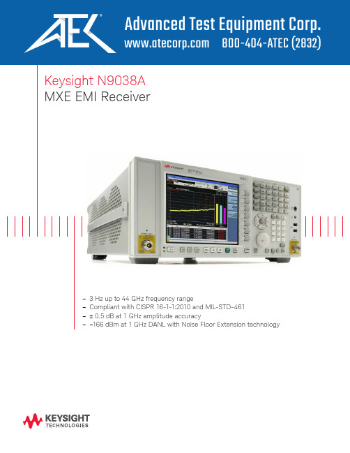
Keysight N9038AMXE EMI Receiver–3 Hz up to 44 GHz frequency range–Compliant with CISPR 16-1-1:2010 and MIL-STD-461–± 0.5 dB at 1 GHz amplitude accuracySummary of Key SpecificationsThe X-Series difference Future-readyOptimize your investment and extend instrument longevity with upgradeable processor, memory, connectivity, and more to keep your test assets current today and tomorrow.Consistent measurement frameworkAchieve measurement integrity across your organization and drive more productivity in less time by leveraging a proven foundation for signal analysis and identical operation across the X-Series instruments.Broadest set of applicationsAddress the changing demands of technology with additionalmeasurement applications, the ability to run software inside the openWindows operating system, and a first-to-market track record in emerging standards.Stay ready, stay in sync, and arrive ahead —with the Keysight X-Series./find/X-SeriesKeep the Test Queue FlowingIn EMC testing, success depends on tools that can help you do more in less time—today and tomorrow. That’s why we created the MXE: it’s a standards-compliant EMI receiver and diagnostic signal analyzer built on an upgradeable platform. In the lab and on the bench, it provides the accuracy, repeatability,and reliability you need to test with confidence.The MXE makes it easy to test in accordance with CISPR 16-1-1:2010 and MIL-STD-461. Choose the frequency coverage you need—up to 3.6, 8.4, 26.5, or44 GHz—and fully test devices with outstanding accuracy and excellent sensitivity across the required ranges.Through the front panel or remotely with software, you can evaluate emissions and identify suspect signals using EMC measurements and a variety of intuitive displays. The extensive set of built-in analysis tools helps you diagnose the causes of noncompliant emissions.With all these capabilities and more, the MXE enables you and your team to keep the test queue flowing.Extend instrument longevity with easy upgradabilityTo keep your instrument current and extend its longevity, the MXE offers easy upgradability of hardware and software capabilities. For example, you can enhance platform performance through CPU and memory upgrades, and add functionality with a simple license key.Leverage the proven reliability of a mature hardware platform Uptime is essential in a test lab and that’s why we built the MXE on the robust Keysight X-Series signal analyzer platform. In addition, the MXE carries the benefits of Keysight’s standard three-year warranty and responsive service and support team.The MXE is ideally suited for high-performance EMC testing in commercial and military applications. The instrument offers a range of CISPR- and MIL-STD-compliant capabilities—detectors, bandwidths, and more—as well as features that further enhance the accuracy and throughput of EMC testing and data analysis.Simplify setupThe MXE contains a number of features that simplify the setup process for compliance measurements. For example, you can use setup tables to create specific measurement configurations for a variety of frequency ranges and antennas. You can also reduce overall setup time by saving and recallingfrequently used custom instrument settings. In addition, the MXE can remotely control switching functions in external LISNs.To accelerate identification of suspect emissions, access the built-in library of limit lines and activate the relevant regulatory limits. You can also define custom limit lines with the easy-to-use editor. To ensure appropriate limit testing, the MXE can automatically correct measured amplitudes for specific transducers, antennas, cabling, and external preamplifiers using customer-configured amplitude correction files.Accelerate data collectionThe MXE is designed to help you see signal activity—quickly and easily—from multiple perspectives. The comprehensive user display allows you to see both a broad overview of the emissions environment and a detailed view of the signal amplitude at a single frequency.Easily capture emissions data using built-in automated scan, search, and measure functions that mirror recommended commercial and military testing procedures. The multi-trace and max hold capabilities let you view emissions from the current position of the device under test (DUT) along with themaximum emissions from all DUT positions. During monitoring, the three color-coded detectors are updated simultaneously to ensure accurate results.The MXE receiver display provides a simplified view into the emissions performance of the DUT.Maximize Throughput in Compliance TestingChoose from traditional frequency or rapid time domain scanning.Easily identify suspect signalsWith built-in measurement and analysis functions, the MXE makes it easy to identify suspect emissions. For example, the unique color-coded trace display capability clearly identifies signals that exceed the selected limit lines and margins.When creating suspect lists, you can choose between traditional frequency scanning and rapid time domain scanning. Time domain scans significantly reduce the time needed to create a list of suspect emissions prior to making final measurements.Built-in limit testing makes it easy to create emission suspect lists. The receiver can automatically move out-of-limit signals to the signal list, where you can perform measurements with the touch of a button.Simplify final measurementsThe list function in the MXE makes it easy to perform final emissionsmeasurements for all supported standards. When you need to control tower or turntable position, internal frequency lists can be passed to automationsoftware. When orientation optimization isn’t required, built-in capabilities help you complete final measurements with ease.When final measurements are complete, you can conveniently create reports in HTML or PDF format with customized content that includes amplitude corrections, limits, scan tables, trace data, signal lists, and screen shots.All-digital IF architectureA digital intermediate frequency (IF) receiver architecture improvesmeasurement accuracy. By comparison, an analog IF architecture implements gain blocks, log amps, resolution bandwidths, and detectors with analog hardware. Even the best of these designs exhibit performance differences when receiver settings are changed from the settings used for calibration. These differences are then exacerbated over temperature.The all-digital IF architectureincludes digital realizations of the key components, which operate on the signal after it has been digitized. Digital IF can improve EMC measurement throughput by minimizing the need for users to bring the signal being measured to the top of the reference level. Analog receivers require this step for every measurement to minimize the effects of analog hardware errors.In addition, digital IF architecturereduces the occurrence of IF overload, even if signals are above the reference level.As an EMI receiver and diagnostic signal analyzer, the MXE puts a wealth of capabilities at yourfingertips. New receiver technology reduces measurement time and ensures you are prepared for future requirements.Go faster with time domain scanningThe MXE offers three types offrequency scanning: swept, stepped, and time domain. Time domain scan decreases total test time by reducing overall prescan collection times when longer measurement dwell times are required.Time domain scan speedsmeasurements by using high-overlap fast Fourier transforms (FFTs) tocollect emissions data simultaneously over an acquisition bandwidth that is multiple resolution bandwidths wide. This is in contrast to frequency-domain measurements, whichcollect data in individual resolution bandwidths.With time domain testing, you can collect suspect lists rapidly, greatly improving overall test time and throughput.Automate click measurementsUse the MXE's built-in disturbance analyzer to easily make discontinuous disturbance, or click, measurements as specified in CISPR 14-1. Simplify and automate data collection, analysis, and report generation for these commonly tested emissions for more efficient testing.Enhance Your Lab with the Latest CapabilitiesComparison of resolution and FFT acquisition bandwidths.FrequencyA m p l i t u d eFFT acquisition bandwidthA m p l i t u d eFrequencyReceiver resolution bandwidthSwept or stepped frequency domain scanTime domain scanDwell for each resolution bandwidthDwell for each FFT bandwidth (multiple resolution bandwidth)Simplify and automate data collection, analysis, and report generation for click measurements.Be ready for APD measurementsThe MXE helps future-proof your lab by offering the amplitude probability distribution (APD) function that is being considered by CISPR foremissions testing of microwave ovens. To characterize slowly-varyingemissions, the APD function displays the probability of an emissionreaching or exceeding a given level. To facilitate use of this new function, the MXE also offers specific limit-line types that can be used with built-in evaluation capabilities to simplify DUT testing.Find the maximum with monitor spectrumIn EMC testing, capturing the maximum value of each emissionfrequency is crucial. Doing so enables accurate characterization of the DUT.To ensure that you have identified the frequencies of maximum emissions in your suspect list, the MXE offers a new feature called monitor spectrum. This feature offers both live-spectrum and meter displays that make it easy to see emission levels and find the maximum while adjusting the center frequency. Ultimately, monitor spectrum improves overall measurement time by reducing the time it takes to prepare your signal list for final measurements.Monitor spectrum identifies frequency of peak emissions.Be ready for future applications with the APD function.The global center frequency feature lets you easily track signals in both the receiver and spectrum analyzer.Gain Insight with Extensive Diagnostic CapabilitiesVerifying product compliance is just one facet of EMI testing. Solving emissions problems can present a wide range of challenges, and the MXE offers a number of tools that will help you see and understand what’s happening.Leverage powerful spectrum analysisInvestigate out-of-compliance emissions with the MXE’s built-in X-Series spectrum analysis capabilities, which include a rich set of resolution and video analysis bandwidths, detectors, and marker functions. In addition, the MXE includes the X-Series PowerSuite measurements for characterization of transmitted signals.Switching between receiver and spectrum analyzer modes is greatlysimplified with the global center frequency function, which links the viewed frequencies. When analyzing an emission, any modification of its frequency will be automatically updated in the MXE’s suspect list, simplifying the final measurement process.Enhance precompliance measurementsYou can leverage the power and usability of the MXE when making precompliance measurements. The Keysight EMI measurement applications (N6141A and W6141A) put the functionality of the MXE inside any of our X-Series signalanalyzers: PXA, MXA, EXA, or CXA. The excellent sensitivity of the X-Series signal analyzers translates into highly accurate emissions measurements.For PXA, MXA or EXA:/find/N6141A For CXA:/find/W6141AStrip Chart mode provides a unique, gap-free view that is useful fortracking DUT performance as a function of turntable or antenna position.Spectrogram displays and the signal-marker capability help you understand the amplitude–and time-varying nature of emissions.RTSA lets you see and understand high-speed transient signals that aredifficult to capture.See amplitude variation vs time with Strip ChartCharacterize the variation of signal amplitude versus time using Strip Chart, a Keysight-exclusive feature which plots data for up to three detectors. All collected data isgapless, with a two-hour time record. This feature is especially useful for capturing the azimuthal emissions characteristics of a DUT when testing on a turntable.The frequency used for the Strip Chart display is coupled to the suspect list, making it easy to view each signal in the suspect list.View varying emissions with spectrograph displaysObserve how emissions spanning a broad spectral range change over time using the built-in spectrograph display. Tracking any variations in spectral data can provide clues about the origins of out-of-compliance emissions.Capture transient signals with real-time spectrum analysisDiagnose high-speed transient signals using real-time spectrum analysis (RTSA) with frequencymask trigger capability. Preselected microwave RTSA enables image-free, over-the-air signal analysis so you can more quickly and easily analyze sources of radiated emissions.Build a Complete EMI Test SolutionProtect Your Investment with an Upgradable PlatformOur qualified Keysight Solution Partners provide a single point of contact to purchase complete EMI measurement solutions that meet commercial and military specifications. In addition to the MXE EMI receiver, they can provide equipment including chambers, probes, towers and antennas, and services such as integration, installation, training, and support. To further simplify testing, they also offer automation software that can meet your specific needs.If you need to go beyond emission and immunity, our solution partners can provide ESD, line harmonics, droop testing, and more.To keep your instrument current and extend its longevity, the MXE offers easy upgradability of hardware and software. When needed, you can enhanceplatform performance through upgradable CPU, memory, disk drives, and I/O ports. Internally, the mechanical assembly has three expansion slots that can accommodate future enhancements.On the software side, simple license-key upgrades are all it takes to add functionality or measurement applications. For example, the external source control option lets the MXE interface with a variety of Keysight signalgenerators, enabling stimulus/response testing up to 20 GHz. For detailed signal analysis, the library of available measurement applications includes analog demodulation, phase noise, and noise figure.Upgrade frequencyThrough return-to-Keysight upgrades, you can extend the frequency range of MXE EMI receivers up to 44 GHz. The receiver maintains its options, applications, and serial number.While the receiver is at the service center for a frequency extension, it is a convenient time to add functionality such as time domain scan for fast FFT-based frequency scanning.For precompliance testing, Keysight also offers frequency upgrades on PXA, MXA, or EXA signal /find/frequencyup11 | Keysight | MXE EMI Receiver N9038A - BrochureMXE Front and Rear PanelsView up to threedifferent prehensive display provides view of spectrum, meters, and suspect list.Second inputpulse-protected to 2 kW.Removable CPU enables processor, memory, and I/O upgrades.Auxiliary/IO port for LISN control.Send and receive SCPI commands over the GPIB interface.Identify signals and view information easily on the 21.4-cm, high-resolution XGA display.Acquire IQ waveform data quickly or control the MXE remotely from an external PC over the USB 2.0 (type-B port) interface.Synchronize other test equipment with the analyzer using the external trigger output signals.Get answers quickly with the comprehensive, context-sensitive embedded help system.Connect external peripherals and transfer data via the USB 2.0 (type-A port) interface.Navigate the interface and help system using the front-panel keys, or a mouse and keyboard.Test devices up to 44 GHz.View the display on an external monitor by connecting to the VGA video output.Two USB 2.0 ports conveniently located on the front of the instrument.Control the MXE remotely over1000Base-T LAN.Removable solid-state drive.Additional solid-state driveavailable for instrument security.Save files fast with the quick-save feature.12 | Keysight | MXE EMI Receiver N9038A - BrochureThis information is subject to change without notice.© Keysight Technologies, 2013 - 2018Published in USA, March 27, 20185990-7422ENRelated LiteratureKeysight MXE EMI receiverPublication title Publication number Data Sheet5990-7421EN Configuration Guide5990-7419EN X-Series Measurement Application Brochure5989-8019EN/find/mxeEvolving Since 1939Our unique combination of hardware, software, services, and people can help you reach your next breakthrough. We are unlocking the future of technology.From Hewlett-Packard to Agilent to Keysight.myKeysight/find/mykeysightA personalized view into the information most relevant to you. /find/emt_product_registrationRegister your products to get up-to-date product information and find warranty information.Keysight Services/find/serviceKeysight Services can help from acquisition to renewal across your instrument’s lifecycle. Our comprehensive service offerings—one-stop calibration, repair, asset management, technology refresh, consulting, training and more—helps you improve product qualityand lower costs.Keysight Assurance Plans/find/AssurancePlansUp to ten years of protection and no budgetary surprises to ensure your instruments are operating to specification, so you can rely on accurate measurements.Keysight Channel Partners/find/channelpartnersGet the best of both worlds: Keysight’s measurement expertise and product breadth, combined with channel partner convenience.For more information on KeysightTechnologies’ products, applications or services, please contact your local Keysight office. The complete list is available at:/find/contactus Americas Canada (877) 894 4414Brazil 55 11 3351 7010Mexico001 800 254 2440United States (800) 829 4444Asia Pacific Australia 1 800 629 485China800 810 0189Hong Kong 800 938 693India 1 800 11 2626Japan 0120 (421) 345Korea 080 769 0800Malaysia 1 800 888 848Singapore 180****8100Taiwan0800 047 866Other AP Countries (65) 6375 8100Europe & Middle East Austria 0800 001122Belgium 0800 58580Finland 0800 523252France 0805 980333Germany ***********Ireland 1800 832700Israel 1 809 343051Italy800 599100Luxembourg +32 800 58580Netherlands 0800 0233200Russia 8800 5009286Spain 800 000154Sweden 0200 882255Switzerland0800 805353Opt. 1 (DE)Opt. 2 (FR)Opt. 3 (IT)United Kingdom0800 0260637For other unlisted countries:/find/contactus(BP-9-7-17)/go/quality Keysight Technologies, Inc.DEKRA Certified ISO 9001:2015Quality Management System。
小米手机 详细参数
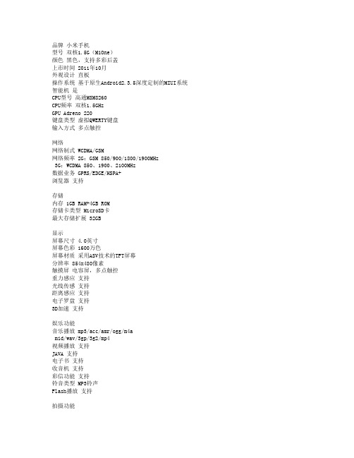
mid/wav/3gp/3g2/mp4 视频播放 支持 JAVA 支持 电子书 支持 收音机 支持 彩信功能 支持 铃音类型 MP3铃声 Flash播放 支持
品牌 小米手机 型号 双核1.5G(MiOne) 颜色 黑色,支持多彩后盖 上市时间 2011年10月 外观设计 直板 操作系统 基于原生Android2.3.5深度定制的MIUI系统 智能机 是 CPU型号 高通MSM8260 CPU频率 双核1.5GHz GPU Adreno 220 键盘类型 虚拟QWERTY键盘 输入方式 多点触控
拍摄功能
后置摄像头 800万像素 前置摄像头 无 传感器类型 CMOS 闪光灯 LED闪光灯 视频拍摄 720p (1280x720,30帧/秒)视频录制
1080p (1920x1080,30帧/秒)视频播放 连拍功能 支持 ISO感光度 支持可选 测光模式 支持可选 白平衡 支持可选 对焦方式 支持可选 对焦区域 支持可选 自动对焦 支持 拍摄风格 支持可选 拍摄场景 支持可选 照片分辨率 最大支持3200x2400像素照片拍摄 其他性能 数字防抖,对比度/饱和度、锐度自主调节
网络 网络制式 WCDMA/GSM 网络频率 2G:GSM 850/900/1800/1900MHz
3G:WCDMA 850、1900、2100MHz 数据业务 GPRS/EDGE/HSPA+ 浏览器 支持
存储 内存 1GB RAM+4GB ROM 存储卡类型 MicroSD卡 最大存储扩展 32GB
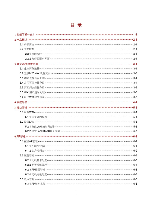
H3C Mini M20无线管理器 用户手册-5W101-正文 (1)
HP OfficeJet 200 Mobile系列使用手册说明书

声明
Microsoft 和 Windows 是 Microsoft Corporation 在美国和/或其他国家/地区 的注册商标或商标。
HP OfficeJet 200
HP OfficeJet 200 Mobile series
使用手册
版权信息
© 2016 版权所有 HP Development Company, L.P.
2016 年 3 月,第 1 版
HP 公司通告
本文档包含的信息如有更改,恕不另行 通知。
保留所有权利。 除非版权法允许,否则 在未经 HP 预先书面许可的情况下,严 禁转载、改编或翻译本手册的内容。
2 使用入门 ...................................................................................................................................................... 2 辅助功能 ................................................................................................................................................................ 2 HP EcoSolutions(惠普与环境) .....................................................................
无线路由器CPU闪存内存芯片列表

WIFI模块应用领域:串口(RS232/RS485)转WiFi、SPI转WiFi;WiFi远程控制/监控、TCP/IP和Wi-Fi协处理器;WiFi遥控飞机、车等玩具领域;WiFi网络收音机、摄像头、数码相框;医疗仪器、数据采集、手持设备;WiFi脂肪秤、智能卡终端;家居智能化;LED照明灯具电源开关仪器仪表、设备参数监测、无线POS机;现代农业、军事领域等其他无线相关二次开发应用。
汽车电子智能电网工业控制NO 中文名称型号方案 flash (M ) D DR (M ) Data Rate (速率)(M) RF Power壳料材质Power(optional)(电源)1 CPE cpe007 9341 8M/16M 32/64M 300 B:28±2,N :24.5 胶壳 18V/1A2 CPE cpe008 9344 8M/16M 64/128M 300 500MW 胶壳 18V/1A3 CPE cpe012 9331 8M/16M 32/64M 150 500MW 胶壳 18V/1A4 CPEcpe0177240+9285 8M/16M 32/64M150100MW胶壳 18V/1A5 CPE cpe020 7240+92858M/16M 32/64M 150 100MW 胶壳 18V/1A6 CPE cpe021 7240+92838M/16M 32/64M 300 500MW 胶壳 18V/1A7 CPE/壁挂APcpe0217240+92838M/16M 32/64M 300 500MW 铁壳 18V/1A8 CPE/壁挂APAP023 9344 16M 128M 300 500MW 铁壳 18V/1A9 CPE/壁挂APSX-AP-23A AR9344 16M64M/128Mdual-frequency/2.4/5.8B:23±2A:22±2铁壳POE06BorPOE12Aor12V1A10 CPE/壁挂APAR9341 8M/16M 64M 300 500MW 铁壳 24V POEor48V POE11 CPE/壁挂APSX-AP-23A AR9344 16M 128M 600 300 铁壳 24V POEor48V POE12 CPE/壁挂APSX-AP-23A AR9344 16M64M/128Mdual-frequency/2.4/5.8B:23±2A:22±2铁壳POE06BorPOE12Aor12V1A13 入墙AP SX-RQAP-01B AR9331 8M/16M 32/64M 150 100MW 胶壳 POE04BorPOE15Aor14 入墙AP SX--RQAP-05A AR9341 8M/16M 32/64M 300 B:18±1.5 胶壳 POE08A15 入墙AP SX-rqap_07A AR9341 8M 64M 300 300MW 胶壳 POE04BorPOE15A16 室外AP SX-AP-03 AR9344 16M 128M dual-frequency600M/2.4/5.82.4GB:27±1.5A:24/26铁壳 POE06B17 吸顶AP SX-AP-10A6 AR9341 8M/16M 32/64M 300 B:28±2 胶壳POE06BorPOE12Aor12V1 A18 吸顶AP SX-AP-15B AR9344 16M 128M dual-frequency600M/2.4/5.8B:27±2,n:20A:22±2,n:20胶壳POE06BorPOE12Aor12V1A19 吸顶AP SX-AP15 9344+938216M 128M300M/2.4g B:27±2,n:20胶壳POE06BorPOE12Aor12V1A20 吸顶AP SX-AP-16A AR9331 8M/16M 32/64M 150 500MW 胶壳POE06BorPOE12Aor12V1 A21 吸顶AP SX-AP19 8197 8M/16M 32/64M 600M 200MW(23DBM)胶壳 POE06B/POE12Aor12V1.22 吸顶AP SX-AP-20A 8192+81968M/16M 32/64M 300M 500MV 胶壳 POE06B/POE12Aor12V1.23 吸顶AP SX-AP-21A 8197DL 8M/16M 32/64M 600Mbps 200mW 胶壳 POE06B/POE12Aor12V1.24 吸顶AP SX-AP-22A1 AR9341 8M/16M 32/64M 300 B:28±2,N:24.5 胶壳 POE06B/POE12A/(falseP24V1A)25 路由LY-03C 9341 8M/16M 64M 300Mbps 500mW 胶壳POE06BorPOE12Aor12V1 A26 路由LY-06B AR9344 8M/16M 64M/128M300Mbps 500mW 胶壳POE06BorPOE12Aor12V1A27 路由LY-08A MTK7620N A18M 64M 300Mbps 100mW 胶壳POE06BorPOE12Aor12V1A28 路由LY-09A AR9341 8M 64M 300Mbps 200mW 胶壳POE06BorPOE12Aor12V1 A29 路由LY-10A MTK7620A 8M/16M 64M/128M300Mbps 500mW 胶壳POE06BorPOE12Aor12V1A30 路由LY-10B MTK7620A 8M/16M 64M/128Mdual-frequency 300Mbps500mW 铁壳POE06BorPOE12Aor12V1A31 路由RT-03C 9341 8/16M 64M 300Mbps 500mW 铁壳POE06BorPOE12Aor12V1 A32 路由RT-06B AR9344 8/16M 64/128M 300Mbps 500mW 铁壳POE06BorPOE12Aor12V1 A33 模块SX-9331MK-01A AR9331 8M/16M 32M/64M 150 50MW34 模块AR9331-PCB-A2 9331 8M/16M 32M/64M 150 50MW35 模块SX-9331MK-04A AR9331 8M/16M 32M/64M 150 50MW36 模块MK-06A AR9344 8M/16M 64M/128Mdual-frequency300M/2.4/5.850MW37 模块SX-9331MK-07A AR9331 8M/16M 32M/64M38 模块SX-9331MK-08AAR9331 16M 64M 150 50MW39 模块SX-9331MK-11A AR9331 8M/16M 32/64M 150 50MW40 模块SX-9331MK-12A AR9331 8M/16M 32/64M 150 50MW41 模块SX-9331MK-13A AR9331 8M/16M 32/64M 150 50MW42 模块SX-MK-15A 9341 8M/16M 32/64M 300 B:23±243 模块SX-AP9331-CPU 9331 8M/16M 32/64M 150 50MW44 模块SX-9331MK-20A 9331 8M/16M 32/64M 150 50MW45 模块SX-9331MK-21A 9331 8M/16M 32/64M46 网卡SHX007C AR9220 NO NO 300 300MW47 网卡SHX002D AR9223 NO NO 300 500MW48 网卡MB92网卡NO NO 300 500MW49 网卡SHX22A 9382 NO NO 300 A:21±1.550 网卡SHX22A1 AR9382 NO NO 300 A:21±1.551 网卡SHX023A 8192 NO NO 300 100MW本文由于作者精力与能力所限,所列型号大部分只能为国产,或YLJ+水货,且也不能列举所有型号和所有版本,但阅读完本文应该已能辨别绝大部分路由的好坏本文如有疏漏,也请各位不吝指正另,路由猫不在本文讨论范围内基本知识储备:1.关键词:解决方案路由厂家实在太多,但是能生产路由主芯片的厂家则很少,路由厂你可以理解为主板厂,而提供无线和主芯片的厂家则可对应理解为intel 和AMD,后者提供解决方案,前者则生产出最终的路由成品卖到消费者手中,如下图所示Athros的官方解决方案:AR9001AP-2NG(AR9130+AR9102+AR)和d-link,TP-link对应的自己的出场成品(后者可能处于成本或者性能考虑,交换芯片更换成Marvell的产品)Athers官方解决方案:AP81图片来自: alan_rei的百度相册d-link dir615 c1版TP-link 841n v3版(交换芯片更改成Marvell 88E6060,性能没有区别)现在无线路由的解决方案主要由两大厂家把持——Broadcom(博通)和Atheros(目前已被Qualcomm高通收购) 以下是两家的产品列表链接:Atheros /wiki/AtherosAtheros被收购后设计的芯片/wiki/Qualcomm_AtherosBroadcom /wiki/Broadcom!!这两家的解决方案将是重点,图例和说明在下一楼上!!还有少部分份额则是由廉价的螃蟹(realtek),Ralink(雷凌)和比较昂贵(还是没有Broadcom贵,博通方案,特别是高端解决方案纯属于坑爹价的类型)的Marvell,Ubicom(只用主芯片的解决方案,没有无线芯片的解决方案,D-link的中高端产品用的最多)方案占据.(早期的主芯片解决方案中还有intel的strongARM插足,如有名的IXP4XX系类)D-link dir-655 A3版解决方案:主芯片Ubicom IP5160U,千兆交换芯片VITESSE VSC7385,无线基带+射频芯片:Atheros AR5416+AR2133(MINI PCI)Ubicom属于比较小众的解决方案,但却是D-link的御用芯片,这种芯片的特点是多线程的性能非常好,这也是D-link 一直再上默默投入的原因,D-link很早就在此基础上开发了自己流控固件,类似于killer网卡的那种QOS,可以设置网络游戏封包的优先权,高端系列的转发也很不错,无线方面一般是配合Atheros的无线网卡,所以无线性能也很有保障,缺点嘛,显而易见,芯片集成度不高,整套方案很繁杂,成本很高belkin 8235-4 V2 (v2000)解决方案:主芯片+无线Ralink RT3025F ,千兆交换芯片realtek RTL8366RB/SB其实Ralink的这个芯片已经集成了一个百兆的交换机,只是这个路由需要千兆的功能所以外加了千兆的交换芯片,Ralink 的解决方案一般集成度比较高,也比较廉价,但是Ralink的由于无线和网络芯片的研发起步的比较早,所以性能还是很不错的,不过产品线比较单一,优势是在信号和传输稳定上,缺点则是芯片的发热(集成度高)和802.11N的极限传输速度上代表产品还有MOTO 2108-N9/D9 , ASUS RT-N13, 华为HG255Ddir 615 A版解决方案:主芯片Marvell 88F5180, 交换芯片Marvell 88E6061, 无线基带+射频芯片Marvell 88W8361P+88W8060 可以看出Marvell的方案一般为全套的解决方案,一般不会与其他芯片混用,而且设计的也比较复杂,成本比较高,典型代表还有Netgear的WNR854T和苹果的airport extreme base station A1354,优点是无线极限传输性能不错,主芯片转发也不错,缺点是方案复杂,成本很高dir-615 F3版或FG版解决方案:主芯片+无线芯片+交换芯片Realtek RTL8196B廉价路由上用烂的方案,性能不是很好,不管是转发抑或是无线覆盖或是传输稳定性,口碑都不好,FG版也成为国内615系列口碑最烂的版本,Realtek做无线相对较少,对这方面投入的没有有线那么多,54M的时候很响亮的8187L USB无线网卡解决方案是其经典的代表作,但是近几年的在无线方面建树较少,所以无线路由选购时尽量不要选采用螃蟹芯片的产品linksys WRV54G V1解决方案:主芯片intel IXP425 @266MHz,交换芯片KENDIN KS8995M, 无线基带+射频芯片Intersil ISL3880 +ISL3686A,自从Intel将strongARM卖给Marvell以后,Intel的解决方案自此从路由市场销声匿迹了,这是04年初上市的老路由,一般Intel解决方案都定位为中小企业及的产品,比家用级高一个档次,这款型号对应的家用版本就是赫赫有名的WRT54G,但显然IXP425的性能是Broadcom BCM4712这类芯片所不能比拟的,所以也注定了他的过高的身价,在市场中的产品也是凤毛麟角,代表产品还有Actiontec MI424WR(此款为IXP425全频版@533MHz ), linksys WRT300N v1,casio RV042注释:进入802.11N无线时代,主要的无线芯片厂都拿出了自己解决方案Broadcom叫INTENSI-FI,Atheros 叫XSPAN,Marvell叫Top Dog,螃蟹和雷凌的叫法不详2.各路由厂家的喜好linksys(Casio):intel(早期),BroadcomASUS:BroadcomNetgear:Broadcom,Marvell(中高端),Atheros(中低端),Realtek(低端)Buffalo:Broacom( 早期),Atheros(目前,高端),Ralink(目前,低端)apple:Marvell+Atheros(前者提供主芯片,后者提供无线)Belkin: Broadcom(中高端),Ralink(中低端)d-link:Ubicon+Atheros(中高端:前者提供主芯片,后者提供无线),Atheros(中低端),Ralink(中低端),Marvell(中端),realtek(低端)moto:Broadcom,RalinkTPlink&Mercury&FAST(普联,水星,迅捷基本算是一家公司):Atheros, MTK(是的你没看错!!!)以上是比较常见的牌子,韩国棒子的ToTolink和斐讯国内也有一定市场,但是我没玩过,所以就不说了。
戴尔 EMC PowerEdge MX5016s 和 MX5000s 安装和服务手册说明书

Dell EMC PowerEdge MX5016s 和 MX5000s 安装和服务手册注、小心和警告注: “注”表示帮助您更好地使用该产品的重要信息。
小心: “小心”表示可能会损坏硬件或导致数据丢失,并说明如何避免此类问题。
警告: “警告”表示可能会造成财产损失、人身伤害甚至死亡。
© 2018 Dell Inc. 或其子公司。
保留所有权利Dell、EMC 和其他商标为 Dell Inc. 或其子公司的商标。
其他商标均为其各自所有者的商标。
2018 - 09Rev. A001 关于本说明文件 (5)2 系统概览 (6)Dell EMC PowerEdge MX5016s 底座概览 (6)底座内部组件 (6)底座的前视图 (7)找到您的系统的服务标签 (7)系统信息标签 (8)Dell EMC PowerEdge MX5000s SAS IOM 概览 (8)PowerEdge MX5000s 模块的前视图 (9)3 MX5016s 的初始系统设置和配置 (10)设置系统 (10)存储底座映射配置 (11)驱动器分配 (11)4 安装和卸下系统组件 (14)安全说明 (14)建议工具 (14)存储底座 (15)从机柜中卸下底座 (15)在机柜中安装底座 (16)驱动器盘位 (17)打开驱动器抽屉 (17)合上驱动器抽屉 (18)驱动器 (19)卸下驱动器挡片 (20)安装驱动器挡片 (21)卸下驱动器托盘 (22)安装驱动器托盘 (23)从驱动器托架中卸下驱动器 (24)将驱动器安装到驱动器托盘中 (25)存储扩充器模块 (26)卸下扩充器模块 (26)安装扩充器模块 (27)SAS IOM 模块 (28)从结构 C 插槽中卸下 MX5016s 挡片 (28)在结构 C 插槽中安装 MX5016s 挡片 (29)从结构 C 插槽中卸下 MX5016s 模块 (30)在结构 C 插槽中安装 MX5016s 模块 (31)目录35 技术规格 (33)底座尺寸 (33)底座重量 (33)支持的操作系统 (33)存储扩展器规格 (34)驱动器规格 (34)模块尺寸 (34)模块重量 (34)环境规格 (34)扩展操作温度 (35)微粒和气体污染规格 (36)6 系统诊断程序和指示灯代码 (37)PowerEdge MX5016s 系统诊断程序和指示灯 (37)系统运行状况指示灯代码 (37)驱动器状态 LED 指示灯 (37)扩充器运行状况状态指示灯 (39)PowerEdge MX5000s 系统诊断程序和指示灯代码 (40)LED 指示灯 (40)7 说明文件资源 (41)8 获得帮助 (43)联系 Dell EMC (43)说明文件反馈 (43)通过使用 QRL 访问系统信息 (43)PowerEdge MX5016s 系统的快速资源定位符 (44)接收自动与 SupportAssist 支持 (44)4目录关于本说明文件本说明文件提供关于存储底座和 SAS IOM 模块的概览、有关安装和装回组件的信息、技术规格以及安组件时要遵循的原则。
3KC ATC6300 自动转换控制器 设备手册说明书
4.5 4.5.1 4.5.2
ATC6300 的显示页面....................................................................................................30 显示页面说明 ...............................................................................................................30 滚动显示页面 ...............................................................................................................41
2.1
ATC6300 自动转换控制器的属性 ..................................................................................15
2.2
兼容的西门子 SENTRON 开关设备.................................................................................17
3.3
电压控制 ......................................................................................................................22
4 产品描述 .........................................................................................................................................25
Dell WB3023杜邦网络摄像头用户指南说明书

Regulatory Model: WB3023tJanuary 2023Rev. A01Dell WebcamWB3023User GuideNOTE: A NOTE indicates important information that helps you make better use of your computer.CAUTION: A CAUTION indicates potential damage to hardware or loss of data if instructions are not followed.WARNING: A WARNING indicates a potential for property damage, personal injury, or death.© 2023 Dell Inc. or its subsidiaries. All rights reserved. Dell, EMC, and other trademarks are trademarks of Dell Inc. or its subsidiaries. Other trademarks may be trademarks of their respective owners.ContentsOverview . . . . . . . . . . . . . . . . . . . . . . . . . . . . . . . . . . . . . . . . . . . .4 What’s in the box (5)Views . . . . . . . . . . . . . . . . . . . . . . . . . . . . . . . . . . . . . . . . . . . . 6 Setting up your webcam on a monitor . . . . . . . . . . . . . . . . . . . . . .7 Setting up your webcam on a tripod . . . . . . . . . . . . . . . . . . . . . . .9 Features . . . . . . . . . . . . . . . . . . . . . . . . . . . . . . . . . . . . . . . . . . . . .10 Specifications . . . . . . . . . . . . . . . . . . . . . . . . . . . . . . . . . . . . . . . . .11 Dell Peripheral Manager . . . . . . . . . . . . . . . . . . . . . . . . . . . . . . . . .12 What is Dell Peripheral Manager? . . . . . . . . . . . . . . . . . . . . . . . . . . . . .12 Installing Dell Peripheral Manager on Windows . . . . . . . . . . . . . . . . . . . . . .12 Dell Display and Peripheral Manager . . . . . . . . . . . . . . . . . . . . . . .13 What is Dell Display and Peripheral Manager on Mac? . . . . . . . . . . . . . . . . . .13 Frequently asked questions . . . . . . . . . . . . . . . . . . . . . . . . . . . . . .14 Troubleshooting . . . . . . . . . . . . . . . . . . . . . . . . . . . . . . . . . . . . . . .15 Statutory information . . . . . . . . . . . . . . . . . . . . . . . . . . . . . . . . . . .17 Getting Help . . . . . . . . . . . . . . . . . . . . . . . . . . . . . . . . . . . . . . . . . .18 Contacting Dell . . . . . . . . . . . . . . . . . . . . . . . . . . . . . . . . . . . . . . .18 Steps . . . . . . . . . . . . . . . . . . . . . . . . . . . . . . . . . . . . . . . . . . . .18│ 3OverviewThe Dell WB3023 webcam offers the following:• 2K video at 30 fps, Full-HD video at 30 fps and HD video at 60 fps• 2x digital zoom• Adjustable field-of-view with autofocus• Built-in microphone• High Dynamic Range (HDR) and video noise reduction support• Additional customization using Dell Peripheral Manager on Windows and Dell Display and Peripheral Manager on Mac4 │ OverviewWhat’s in the boxOverview │ 56 │ OverviewViews1. Multi-element lens and Sony sensor2. MicrophoneNote: Microphone enabled via Dell Peripheral Manager software on Windows andDell Display and Peripheral Manager software on mac.3. LED light indicator4. Integrated privacy shutter5. Tripod-adapter threadNote: Tripod not included.6. Universal mounting clip 123456Setting up your webcam on a monitor │ 71. Open the universal mounting clip as seen below.2. Place the webcam on the monitor bezel and adjust the foot on the universal mounting clip at the back of the monitor until the webcam sits firmly on the monitor bezel.3. Control the privacy shutter by sliding left before using and gently slide to the right when not in use.Setting up your webcam on a monitorN OTE: It is recommended to have an active internet connection on your computer for the best setup experience.N OTE: Download the Dell Peripheral Manager or Dell Display and Peripheral Manager from/support/wb3023.8 │ Setting up your webcam on a monitorNOTE : Remove the sticker on the webcam.NOTE : Manually adjust the webcam up/down to the best position.4. Connect the USB-A end of the cable to a USB-A port on your computer, desktop, or monitor.5. Use the on-screen instructions on Dell Peripheral Manager application on Windows or DellDisplay and Peripheral Manager application on Mac, to customise the camera settings.Setting up your webcam on a tripod │ 9NOTE : Tripod is not included in the box.1. Align the thread on the universal mount with the mounting screw on the tripod. Rotate the tripod adapter until it is firmly fixed on the tripod.2. Connect the camera USB cable to a USB-A port on your computer, desktop, or monitor . Control the privacy shutter by sliding left before using and gently slide to the right when not in use.3. Use the on-screen instructions on Dell Peripheral Manager application on Windows or Dell Display and Peripheral Manager application on Mac, to customise the camera settings.Setting up your webcam on a tripodFeaturesAdjustable field-of-view:The Dell WB3023 webcam features a 78 degree field-of-view (FOV) and can be changed to 65 based on the user's preference. Adjusting the FOV allows you to customise the video output to your external environment.HDR and Video Noise Reduction :The Dell WB3023 webcam's HDR guarantees superior picture quality in extreme lighting environments, while video noise reduction automatically eliminates grainy images in low light.Facial Detection Auto Exposure :The Dell WB3023 comes with an intelligent image processing technology that detects the human face and automatically adjust the exposure to look just right in any lighting condition,Microphone :The built-in microphone enables clear communication optmised for personal workspace.10 │ FeaturesSpecificationsWebcam camera stream data Stream video encoding engine Video format supportedField-of-ViewFocusZoomAuto Light Correction Microphone*LED indicatorsSupported operating systemOperating temperature (maximum)USB 2.0 cableMJPEG encoding engine2K QHD at 30 fpsFull-HD at 30 fpsHD at 30 or 60 fps65 / 78 degreeAuto Focus2x digital zoomHDR and Auto White BalanceVideo Noise ReductionOmni-directionalPick-up range up to 2mON: Webcam is in useOFF: Webcam is off or not in useWindows 10, 64-bitWindows 11, 64-bitMac OS 12.3.1The webcam can operate at a maximum ambient temperature of 40°C*Microphone can be enabled via Dell Peripheral Manager software on Windows and Dell Display and Peripheral Manager software on MacSpecifications │ 11Dell Peripheral ManagerWhat is Dell Peripheral Manager?The Dell Peripheral Manager application helps you manage and set up various Dell Peripherals connected to your Windows OS computer. It allows the user to make changes to settings of the device and provides additional customization like enabling HDR, adjusting Field of View to 68, 2x Zoom, activating the Microphone and more.Installing Dell Peripheral Manager on WindowsWhen you connect the device to your computer for the first time, Dell Peripheral Manageris downloaded and installed automatically through the Windows Update process.NOTE : If Dell Peripheral Manager does not appear within a few minutes, you can manually install the software by checking for updates.Download the Dell Peripheral Manager from /support/wb3023.For more details on the application and the customizations for Dell WB3023 on Windows OS, refer to the Dell Peripheral Manager's User’s Guide at /support/wb3023.12 │Dell Peripheral ManagerDell Display and Peripheral Manager │ 13Dell Display and Peripheral ManagerWhat is Dell Display and Peripheral Manager on Mac?Dell Display and Peripheral Manager (DDPM) is an Apple macOS application to manage a monitor or a group of monitors or webcams.Dell Display and Peripheral Manager allows manual adjustment of the displayed image,assignment of automatic settings, energy management, window organization, image rotation, webcam preview, webcam settings and other features on selected Dell monitors and webcams.NOTE: To activate the microphone, please enable the setting on the Dell Display and Peripheral Manager.Download the Dell Display and Peripheral Manager from /support/wb3023.For more details on the application and the customizations for Dell WB3023 on Mac OS, refer to the Dell Display and Peripheral Manager's User’s Guide at /support/wb3023.Frequently asked questions1. What is the recommended configuration to install the Dell WB3023 webcam?Windows 10, 64-bit or newer.MacOS 12.3.1 or newer.One USB type-A port.2. How do I know if my camera is on?The Dell WB3023 webcam has a status-LED on the front lens that stays on (white light) when the camera is in use. The status-LED is solid white when the webcam in use.3. Can I use the Dell WB3023 webcam with a docking station or a USB Hub?Yes, you can configure the webcam through a docking station or a USB hub connected to your computer.4. Can I connect my webcam directly to a monitor?Yes, the Dell WB3023 can be connected to the monitor directly. Ensure that the monitor’s data up-stream cable is connected to the computer, without which the webcam will not work. In case the monitor does not have a data up-stream port, the webcam cannot be connected to the monitor and must be connected to the computer directly.5. How do I activate the Microphone on the webcam?The microphone will be disabled by default and must be enabled using the Dell Peripheral Manager(DPM) for Windows or Dell Display and Peripheral Manager (DDPM) for Mac OS application. After installing the application and setting up the webcam, go to More Settings > Audio > Switch the toggle on for Camera Microphone on DPM or select On for Camera Microphone setting under Webcam > Webcam Control tab in DDPM.6. How do I set up my webcam on a Mac?The process for setting up the webcam remains the same on MacOS or Windows.However, certain Apple devices do not come with a USB-A port. In such instances, the webcam must be connected through a device-compatible dongle, docking station or a Display Monitor USB hub.7. Can I use the webcam to take photos and record videos?Yes, Dell WB3023 is capable of capturing high-quality photos and videos. This can be done using the default Windows Camera app or any other webcam-enabled application. 8. Do my camera setting adjustment in DPM or DDPM changes every time Idisconnect and reconnect the webcam from the device?The DPM or DDPM application stores user’s preferred settings and will only change if manually edited. Disconnecting and reconnecting the webcam will not change the user settings and you can just pick-up where you left off.14 │Frequently asked questionsTroubleshootingProblem Possible solutionsRecommended steps for webcam issues For any issues with the Dell WB3023 webcam, it is recommended to start by following these steps:1. Update the BIOS on your computer to the latestavailable version.2. Update the operating system to the latest availableversion.3. Update the USB-host and Thunderbolt driver onyour computer.Update the firmware on the Dell WB3023 webcam to the latest version from /support/wb3023.Webcam not detected 1. Try disconnecting and reconnecting the USB cable.2. Check if the webcam is detected in Device Manager.3. Disconnect the webcam from any docking stationsor USB-hubs, and connect it directly to thecomputer.Image or video shows artefacts and flickering, due to interference from LED or Florescent light sources T o resolve this issue, additional customization is needed based on your environmental lighting. For details onhow to resolve this, go to DPM or DDPM > Color and Image:1 .Switch on the Anti Flicker toggle.2 .T oggle between 50Hz and 60Hz to check which option eliminates the flickering.Troubleshooting │ 15Unable to install Dell Peripheral Manager on ARM-based Windows computers Dell Peripheral Manager is not supported on ARM-based Windows computers.Webcam does not work with Dell Peripheral Manager and Dell Display and Peripheral Manager and Windows or Mac Camera app after hot-plugging the webcam to the computer Wait for a few seconds after unplugging the camera before re-connecting it to the computer.Webcam not detected when connected to a docking station or USB hub 1. Connect the dock or hub to a USB2.0/3.0 or USB-Cport on the computer.2. Update the firmware on the dock to the latestversion.Webcam is unable to automatically set the frame-rate and exposure Auto-exposure and frame rate feature only function at low light condition and it is supported when HDR is turned off.T oggle off HDR on the DPM or DDPM to use auto-exposure and frame rate feature.Microphone is not functional 1. Check if the microphone is enabled in the DPM orDDPM application.2. Check if the computer has permission to access thewebcam in the Windows/MacOS system settings.3. Try using the webcam’s microphone on a differentapplication. Adjust the application settings to choosewebcam as the input device.4. Disconnect and reconnect the webcam.5. If the webcam is connected to the computerthrough a docking station or monitor, try connectingthe webcam directly to the computer.16 │ TroubleshootingStatutory informationWarrantyLimited warranty and return policiesDell WB3023 webcam ships with a 3-year limited hardware. If purchased together with a Dell system, it will follow the system warranty.For U.S. customers:This purchase and your use of this product are subject to Dell’s end user agreement, which you can find at /terms This document contains a binding arbitration clause. For European, Middle Eastern and African customers:Dell-branded products that are sold and used are subject to applicable national consumer legal rights, the terms of any retailer sale agreement that you have entered into (which will apply between you and the retailer) and Dell’s end user contract terms.Dell may also provide an additional hardware warranty—full details of the Dell end user contract and warranty terms can be found by going to , selecting your country from the list at the bottom of the “home” page and then clicking the “terms and conditions”link for the end user terms or the “support” link for the warranty terms.For non-U.S. customers:Dell-branded products that are sold and used are subject to applicable national consumer legal rights, the terms of any retailer sale agreement that you have entered into (which will apply between you and the retailer) and Dell’s warranty terms. Dell may also provide an additional hardware warranty full details of Dell’s warranty terms can be found by going to , selecting your country from the list at the bottom of the “home” page and then clicking the “terms and conditions” link or the “support” link for the warranty terms.Statutory information │ 17Getting HelpContacting DellNOTE:If you do not have an active Internet connection, you can find contactinformation on your purchase invoice, packing slip, bill, or Dell product catalog.Dell provides several online and telephone-based support and service options. Availability varies by country and product, and some services may not be available in your area. T o contact Dell for sales, technical support, or customer service issues:StepsGo to /support.1. Select your support category.2. Verify your country or region in the Choose a Country/Region drop-down list at thebottom of the page.3. Select the appropriate service or support link based on your need.18 │Getting Help。
电容式无线咪

无线麦克风电路图
这个无线麦克风对初学者来说非常的适合,可以简单的做到跟老手一样的品质。
它已被成功的安装在吉他中使用过,因为许多人要求够得到较高功率且灵敏度高的FM 麦克风,所以Harry Lythall 设计了这个新的麦克风线路(第5 版),而且频率的穏定度也较高,而且理论上可到1 公里的距离,这个线路里增加了一个10dB 的高频缓冲器及一个音频放大器。
许多制作无线发射器时常发现的问题就是线圈的制作,这个制作L1
线圈为3.25 圈的螺旋状,直接将线圈制作在电路板中,所以不用再另外制作线圈。
两个
BC547晶体管可以自行更换成任一型小讯号的NPN 晶体管如2N2222等..终端用的BC557也是一般通用的晶体。
若输入端要改为主动式麦克风,必须移除4.7K 电阻。
经设计者的测试实际穏定的距离达700 公尺远,效果真的不错。
零件的配置如下图:
PC 板的大小为50mm*25mm ,请自行以复印机或影像处理软件调整大小,
曝光时注意要反面。
成品图如下:
至于如何调整频率呢?
上图中你可以看到一个小小的秘密装置,跨接在电路12P 电容上,这个小装置可以微量调整电容量,所以在电路中可以些微的调降发射的频率,这个装置只是两条被扭绞在一起的绝缘的单芯导线,长约2 公分,若想增大电容(降低频率)就把它再扭多圈点,如想再减低电容(升高频率)就把言两条绞线剪短一点,利用这个方法来调整频率。
再次感谢Harry Lythall 。
最小抑菌浓度测定
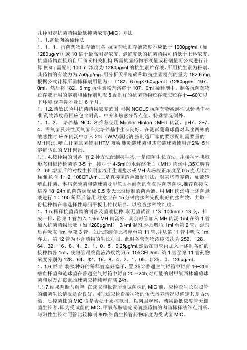
几种测定抗菌药物最低抑菌浓度(MIC)方法1。
1.常量肉汤稀释法1。
1。
1。
抗菌药物贮存液制备抗菌药物贮存液浓度不应低于1000μg/ml(如1280μg/ml)或10倍于最高测定浓度。
溶解度低的抗菌药物可稍低于上述浓度。
抗菌药物直接购自厂商或相关机构.所需抗菌药物溶液量或粉剂量可公式进行计算.例如:需配制100 ml浓度为1280μg/ml的抗生素贮存液,所用抗生素为粉剂,其药物的有效力为750μg/mg。
用分析天平精确称取抗生素粉剂的量为182.6 mg.根据公式计算所需稀释剂用量为:(182。
6 mg×750μg/ml)/1280μg/ml=107。
0ml,然后将182。
6 mg抗生素粉剂溶解于107。
0ml稀释剂中。
制备抗菌药物贮存液所用的溶剂和稀释剂见表5.配制好的抗菌药物贮存液应贮存于—60℃以下环境,保存期不超过6个月。
1。
1.2.药敏试验用抗菌药物浓度范围根据NCCLS抗菌药物敏感性试验操作标准,药物浓度范围应包含耐药、中介和敏感分界点值,特殊情况例外。
1。
1。
3。
培养基NCCLS推荐使用Mueller-Hinton(MH)肉汤,pH7。
2~7。
4。
需氧菌及兼性厌氧菌在此培养基中生长良好。
在测试葡萄球菌对苯唑西林的敏感性时,应在肉汤中加入2%(W/V)氯化钠,按制造厂家的要求配制需要量的MH肉汤。
嗜血杆菌属菌使用HTM肉汤,肺炎链球菌和其它链球菌使用含2%~5%溶解马血的MH肉汤。
1.1。
4.接种物的制备有2种方法配制接种物,一是细菌生长方法,用接种环挑取形态相似待检菌落3-5个,接种于4-5ml的水解酪蛋白(MH)肉汤中,35℃孵育2—6h.增菌后的对数生长期菌液用生理盐水或MH肉汤校正浓度至0.5麦氏比浊标准,约含1~2×10⁸CFU/ml.二是直接菌落悬液配制法,对某些苛养菌,如流感嗜血杆菌、淋病奈瑟菌和链球菌及甲氧西林耐药的葡萄球菌等菌株,推荐直接取培养18~24h的菌落调配成0.5麦氏比浊标准的菌悬液。
主流频段最强者,摩托罗拉摩路由M1评测

主流频段最强者,摩托罗拉摩路由M1评测随着互联网的不断发展,越来越多人生活更加依赖于网络,而Wi-Fi 则成为了大多数用户连接到网络的重要手段。
然而,对于家庭用户而言,不同的家居环境对于Wi-Fi 信号的影响非常大,如何选择一款合适的路由器作为家里Wi-Fi 载体也成为了不少用户遇到的最大难题。
不过,作为通讯行业的佼佼者,摩托罗拉自然了解到不同用户使用网络的需求,推出了一款适用场景更为广阔的路由器——摩托罗拉摩路由M1。
究竟这款摩路由M1 有着怎样的特殊技能?我们一起来看一下吧。
摩路由M1 采用了以白色为主色调包装设计风格,正面采用了产品硬照作为主体,让用户从接触到包装后即能够对产品外形有了一定的认识。
除了产品硬照之外,摩路由M1 的包装就仅仅印上了产品的主要卖点以及摩托罗拉Logo,通体极为简洁,给人感觉十分舒适。
作为一款家用路由器,摩路由M1 在外形设计上也下了一定的功夫。
虽然路由器选择了白色作为主色调,但搭配激光咬花工艺以及正面的纹理设计之后,摩路由M1 看起来也就没那么单调了。
此外,摩路由M1 采用了类拱桥式设计,让外形更美观的同时也为其带来了更好的散热表现。
与其他路由器一样,摩路由M1 的所有接口都放置在机身的背部,分别为DC 电源接口、一个WAN 接口、四个LAN 接口以及一个隐藏式复位键,基本满足了绝大部分用户对于路由器的网络接口需求了。
较为遗憾的是,摩路由M1 并没有设置实体开关按键,同时也没有预留USB 接口,用户想要与存储设备进行数据交换的话,也只能通过Wi-Fi 了。
翻看摩路由M1 包装上的参数,我们看到摩路由M1 支持802.11b/g/n 以及802.3/3U 传输协议,工作频率主要为2.4GHz,发射功率最高20dBm,无线速率达到了800Mbps,为目前市面上单2.4GHz 频段网速最快的。
而在天线设计上,摩路由M1 则选择了配备4 天线作为信号发射塔,希望能够获得更稳定的信号表现。
- 1、下载文档前请自行甄别文档内容的完整性,平台不提供额外的编辑、内容补充、找答案等附加服务。
- 2、"仅部分预览"的文档,不可在线预览部分如存在完整性等问题,可反馈申请退款(可完整预览的文档不适用该条件!)。
- 3、如文档侵犯您的权益,请联系客服反馈,我们会尽快为您处理(人工客服工作时间:9:00-18:30)。
+R1=100mV S R R (SR+R )V +SR( +100mV)R I – ( +100mV)R =R =–10002200VTRI PSFor this example:=30A (trip current)I L=100mVVTRI PS S TH VTRI PVTRI PL U R C EGeneral DescriptionThe MIC5013 is an 8-pin MOSFET driver with over-current shutdown and a fault flag. It is designed to drive the gate of an N-channel power MOSFET above the supply rail high-side power switch applications. The MIC5013 is compatible with standard or current-sensing power MOSFETs in both high- and low-side driver topologies.The MIC5013 charges a 1nF load in 60µs typical and protects the MOSFET from over-current conditions. The current sense trip point is fully programmable and a dynamic threshold allows high in-rush current loads to be started. A fault pin indicates when the MIC5013 has turned off the FET due to excessive current.Other members of the Micrel driver family include the MIC5011 minimum parts count driver and MIC5012 dual driver.Features• 7V to 32V operation• Less than 1µA standby current in the “OFF” state • Available in small outline SOIC packages• Internal charge pump to drive the gate of an N-channel power FET above supply• Internal zener clamp for gate protection• 60µs typical turn-on time to 50% gate overdrive • Programmable over-current sensing• Dynamic current threshold for high in-rush loads • Fault output pin indicates current faults •Implements high- or low-side switchesApplications• Lamp drivers• Relay and solenoid drivers • Heater switching • Power bus switching •Motion controlTypical Application Protected under one or more of the following Micrel patents:patent #4,951,101; patent #4,914,546Note: The MIC5013 is ESD sensitive.Micrel, Inc. • 2180 Fortune Drive • San Jose, CA 95131 • USA • tel + 1 (408) 944-0800 • fax + 1 (408) 474-1000 • Ordering InformationPart NumberTemperature Range Package Standard Pb-Free MIC5013BNMIC5013YN–40ºC to +85ºC8-pin PlasticDIP MIC5013BM MIC5013YM –40ºC to +85ºC8-pin SOICFigure 1. High-Side Driver with Current-Sensing MOSFETPin Description (Refer to Figures 1 and 2)Pin NumberPin Name Pin Function1 Input Resets current sense latch and turns on power MOSFET when taken above threshold (3.5V typical). Pin 1 requires <1µA to switch.2ThresholdSets current sense trip voltage according to:R=+ 10002200VTRI PTHwhere R TH to ground is 3.3k to 20kΩ. Adding capacitor C TH increases the trip voltage at turn-on to 2V. Use C TH =10µF for a 10ms turn-on time con-stant.3 SenseThe sense pin causes the current sense to trip when V SENSE is V TRIP above V SOURCE . Pin 3 is used in conjunction with a current shunt in the source of a 3 lead FET or a resistor R S in the sense lead of a current sensing FET. 4 SourceReference for the current sense voltage on pin 3 and return for the gate clamp zener. Connect to the load side of current shunt or kelvin lead of cur-rent sensing FET. Pins 3 and 4 can safely swing to –10V when turning off inductive loads.5 Ground6 Gate Drives and clamps the gate of the power FET. Pin 6 will be clamped to ap-proximately –0.7V by an internal diode when turning off inductive loads.7 V + Supply pin; must be decoupled to isolate from large transients caused by the power FET drain. 10µF is recommended close to pins 7 and 5.8FaultOutputs status of protection circuit when pin 1 is high. Fault low indicates normal operation; fault high indicates current sense tripped.Absolute Maximum Ratings (Note 1, 2)Input Voltage, Pin 1–10 to V +Threshold Voltage, Pin 2 –0.5 to +5V Sense Voltage, Pin 3 –10V to V +Source Voltage, Pin 4 –10V to V +Current into Pin 4 50mA Gate Voltage, Pin 6–1V to 50V Supply Voltage (V +), Pin 7 –0.5V to 36V Fault Output Current, Pin 8 –1mA to +1mAJunction Temperature150°COperating Ratings (Notes 1, 2)Power Dissipation 1.25W θJA (Plastic DIP) 100°C/W θJA (SOIC)170°C/W Ambient Temperature: B version –40°C to +85°C Storage Temperature –65°C to +150°CLead Temperature260°C (Soldering, 10 seconds)Supply Voltage (V +), Pin 7 7V to 32V high side7V to 15V low sideFault V+Gate 12348MIC5013Gnd 765Thresh Sense Source InputPin ConfigurationElectrical Characteristics (Note 3, 5)Test circuit. T A = –55°C to +125°C, V+ = 15V, all switches open, unless otherwise specified.Parameter Conditions Min Typical Max Units Supply Current, I7V+ = 32V V IN = 0V, S4 closed 0.1 10 µAV IN = V S = 32V 8 20 mA Logic Input Voltage, V IN V+ = 4.75V Adjust V IN for V GATE low 2 VAdjust V IN for V GATE high 4.5 VV+ =15V Adjust V IN for V GATE high 5.0 V Logic Input Current, I1V+ = 32V V IN = 0V –1 µAV IN = 32V 1 µA Input Capacitance Pin 1 5 pF Gate Drive, V GATE S1, S2 closed, V+ = 7V, I6 = 0 13 15 VV S = V+, V IN = 5V V+ = 15V, I6 = 100 µA 24 27 V Zener Clamp, S2 closed, V IN = 5V V+ = 15V, V S = 15V 11 12.5 15 V V GATE – V SOURCE V+ = 32V, V S = 32V 11 13 16 V Gate Turn-on Time, t ON V IN switched from 0 to 5V; measure time 60 200 µs(Note 4) for V GATE to reach 20VGate Turn-off Time, t OFF V IN switched from 5 to 0V; measure time 4 10 µsfor V GATE to reach 1VThreshold Bias Voltage, V2I2 = 200 µA 1.7 2 2.2 V Current Sense Trip Voltage, S2 closed, V IN = 5V, V+ = 7V, S4 closed 75 105 135 mV V SENSE – V SOURCE Increase I3I2 = 100 µA V S = 4.9V, S4 open 70 100 130 mVV+ = 15V S4 closed 150 210 270 mVI2 = 200 µA V S = 11.8V, S4 open 140 200 260 mVV+ = 32V V S = 0V, S4 open 360 520 680 mVI2 = 500 µA V S = 25.5V, S4 open 350 500 650 mV Peak Current Trip Voltage, S3, S4 closed, 1.6 2.1 V V SENSE – V SOURCE V+ = 15V, V IN = 5VFault Output Voltage, V8V IN = 0V, I8 = –100 µA 0.4 1 VV IN = 5V, I8 = 100 µA, current sense tripped 14 14.6 V Note 1. Absolute Maximum Ratings indicate limits beyond which damage to the device may occur. Electrical specifications do not apply when operating the device beyond its specified Operating Ratings.Note 2.The MIC5010 is ESD sensitive.Note 3.Minimum and maximum Electrical Characteristics are 100% tested at T A = 25°C and T A = 85°C, and 100% guaranteed over the entire range. Typicals are characterized at 25°C and represent the most likely parametric norm.Note 4.Test conditions reflect worst case high-side driver performance. Low-side and bootstrapped topologies are significantly faster—see Applications Information.Note 5.Specification for packaged product only.Test CircuitTypical Characteristics024681012Supply CurrentSUPPLY VOLTAGE (V)S U P P L Y C U R R E N T (m A )3691215SUPPLY VOLTAGE (V)02468101214V G A T E – V + (V )DC Gate Voltage above SupplyI8V INT U R N -O N T I M E(m S )SUPPLY VOLTAGE (V)High-side Turn-on Time*0.51.01.52.02.53.03.5050100150200250300350T U R N -O N T I M E (µS )SUPPLY VOLTAGE (V)High-side Turn-on Time** Time for gate to reach V + + 5V in test circuit with VS = V + – 5V (prevents gate clamp from interfering with measurement).Typical Characteristics (Continued)SUPPLY VOLTAGE (V)1310301003001000T U R N -O N T I M E (µS )Low-side Turn-on TimeSUPPLY VOLTAGE (V)T U R N -O N T I M E (µS )Low-side Turn-on Time1030100300100030000.50.751.01.251.51.752.0–25255075100125DIE TEMPERATURE (°C)N O R M A L I Z E D T U R N -O N T I METurn-on TimeSUPPLY VOLTAGE (V)T U R N -O F F T I M E (µS )1020304050Turn-off TimeC H A R G E -P U M P C U R R E N T (µA )51015202530SUPPLY VOLTAGE (V)Charge PumpBlock DiagramApplications InformationFunctional Description (refer to block diagram)The various MIC5013 functions are controlled via a logic block connected to the input pin 1. When the input is low, all functions are turned off for low standby current and the gate of the power MOSFET is also held low through 500Ω to an N-channel switch. When the input is taken above the turn-on threshold (3.5V typical), the N-channel switch turns off and the charge pump is turned on to charge the gate of the power FET. A bandgap type voltage regulator is also turned on which biases the current sense circuitry.The charge pump incorporates a 100kHz oscillator and on-chip pump capacitors capable of charging 1nF to 5V above supply in 60µs typical. The charge pump is capable of pumping the gate up to over twice the supply voltage. For this reason, a zener clamp (12.5V typical) is provided between the gate pin 6 and source pin 4 to prevent exceed-ing the V GS rating of the MOSFET at high supplies.The current sense operates by comparing the sense volt-age at pin 3 to an offset version of the source voltage at pin 4. Current I2 flowing in threshold pin 2 is mirrored and returned to the source via a 1kΩ resistor to set the offset, or trip voltage. When (V SENSE – V SOURCE) exceeds V TRIP, the current sense trips and sets the current sense latch to turn off the power FET. An integrating comparator is used to reduce sensitivity to spikes on pin 3. The latch is reset to turn the FET back on by “recycling” the input pin 1 low and then high again.A resistor R TH from pin 2 to ground sets I2, and hence V TRIP. An additional capacitor C TH from pin 2 to ground creates a higher trip voltage at turn-on, which is necessary to prevent high in-rush current loads such as lamps or capacitors from false-tripping the current sense.When the current sense has tripped, the fault pin 8 will be high as long as the input pin 1 remains high. However, when the input is low the fault pin will also be low. Construction HintsHigh current pulse circuits demand equipment and assembly techniques that are more stringent than normal low current lab practices. The following are the sources of pitfalls most often encountered during prototyping: Supplies: many bench power supplies have poor transient response. Circuits that are being pulse tested, or those that operate by pulse-width modulation will produce strange results when used with a supply that has poor ripple rejection, or a peaked transient response. Monitor the power supply voltage that appears at the drain of a high-side driver (or the supply side of the load in a low-side driver) with an oscilloscope. It is not un-common to find bench power supplies in the 1kW class that overshoot or undershoot by as much as 50% when pulse loaded. Not only will the load current and voltage measure-ments be affected, but it is possible to over-stress various components—especially electrolytic capacitors—with pos-sibly catastrophic results. A 10µF supply bypass capacitor at the chip is recommended.Residual Resistances: Resistances in circuit connections may also cause confusing results. For example, a circuit may employ a 50mΩ power MOSFET for low drop, but careless construction techniques could easily add 50 to 100mΩ resistance. Do not use a socket for the MOSFET. If the MOSFET is a TO-220 type package, make high-current drain connections to the tab. Wiring losses have a profound effect on high-current circuits. A floating millivoltmeter can identify connections that are contributing excess drop under load.V I =20A (trip current)L V TRI P I L VTRI P= 200mVFor this example:R=2200–1000V TRI PTHR =S+*International Resistive CompanyR1=R2=100ΩR =R =1mAV 100mV+2200–1000+I L For this example:I =10A (trip current)LV =100mV TRI PV TRI PV TRI PS TH Circuit TopologiesThe MIC5013 is suited for use in high- or low-side driver applications with over-current protection for both current-sensing and standard MOSFETs. In addition, the MIC5013 works well in applications where, for faster switching times, the supply is bootstrapped from the MOSFET source out-put. Low voltage, high-side drivers (such as shown in the Test Circuit) are the slowest; their speed is reflected in the gate turn-on time specifications. The fastest drivers are the low-side and bootstrapped high-side types. Load current switching times are often much faster than the time to full gate enhancement, depending on the circuit type, the MOS-FET, and the load. Turn-off times are essentially the same for all circuits (less than 10µs to V GS = 1V). The choice of one topology over another is based on a combination of considerations including speed, voltage, and desired system characteristics. Each topology is described in this section. Note that I L , as used in the design equations, is the load current that just trips the over-current comparator.Low-Side Driver with Current Shunt (Figure 2). The over-current comparator monitors RS and trips if I L × R S exceeds V TRIP . R is selected to produce the desired trip voltage.As a guideline, keep V TRIP within the limits of 100mV and 500mV (R TH = 3.3kΩ to 20kΩ). Thresholds at the high end offer the best noise immunity, but also compromise switch drop (especially in low voltage applications) and power dissipation.The trip current is set higher than the maximum expected load current—typically twice that value. Trip point accuracy is a function of resistor tolerances, comparator offset (only a few millivolts), and threshold bias voltage (V2). The val-ues shown in Figure 2 are designed for a trip current of 20 amperes. It is important to ground pin 4 at the current shunt R S , to eliminate the effects of ground resistance.A key advantage of the low-side topology is that the load sup-ply is limited only by the MOSFET BVDSS rating. Clamping may be required to protect the MOSFET drain terminal fromFigure 2. Low-Side Driverwith Current ShuntFigure 3. High-Side Driverwith Current Shunt† Suppliers of Kelvin-sensed power resistors:Dale Electronics, Inc., 2064 12th Ave., Columbus, NE 68601. Tel: (402) 564-3131International Resistive Co., P .O. Box 1860, Boone, NC 28607-1860. Tel: (704) 264-8861Kelvin, 14724 Ventura Blvd., Ste. 1003, Sherman Oaks, CA 91403-3501. Tel: (818) 990-1192 RCD Components, Inc., 520 E. Industrial Pk. Dr., Manchester, NH 03103. Tel: (603) 669-0054 Ultronix, Inc., P .O. Box 1090, Grand Junction, CO 81502. Tel: (303) 242-0810V R C ES R R I –R =LVTRI P V TRI PS R=–10002200VTRI PTHFor this example:=20A (trip current)I L =100mVVTRI PApplications Information (Continued)inductive switching transients. The MIC5013 supply should be limited to 15V in low-side topologies; otherwise, a large current will be forced through the gate clamp zener.Low-side drivers constructed with the MIC501X family are also fast; the MOSFET gate is driven to near supply imme-diately when commanded ON. Typical circuits achieve 10V enhancement in 10µs or less on a 12 to 15V supply.High-Side Driver with Current Shunt (Figure 3). The comparator input pins (source and sense) float with the current sensing resistor (R S ) on top of the load. R1 and R2 add a small, additional potential to V TRIP to prevent false-triggering of the over-current shutdown circuit with open or inductive loads. R1 is sized for a current flow of 1mA, while R2 contributes a drop of 100mV. The shunt voltage should be 200 to 500mV at the trip point. The example of Figure 3 gives a 10A trip current when the output is near supply. The trip point is somewhat reduced when the output is at ground as the voltage drop across R1 (and therefore R2) is zero.High-side drivers implemented with MIC5013 drivers are self-protected against inductive switching transients. During turn-off an inductive load will force the MOSFET source 5V or more below ground, while the driver holds the gate at ground potential. The MOSFET is forced into conduction, and it dissipates the energy stored in the load inductance. The MIC5013 source and sense pins (3 and 4) are designed to withstand this negative excursion without damage. External clamp diodes are unnecessary.Current Shunts (R S ). Low-valued resistors are necessary for use at R S .Values for R S range from 5 to 50mΩ, at 2 to 10W. Worthy of special mention are Kelvin-sensed, “four-terminal” units supplied by a number of manufacturers †(see next page). Kelvin-sensed resistors eliminate errors caused by lead and terminal resistances, and simplify product assembly. 10% tolerance is normally adequate, and with shunt potentials of 200mV thermocouple effects are insignificant. Temperature coefficient is important; a linear, 500 ppm/°C change will contribute as much as 10% shift in the over-current trip point. Most power resistors designed for current shunt service drift less than 100 ppm/°C.Low-Side Driver with Current Sensing MOSFET (Figure 4). Several manufacturers now supply power MOSFETs in which a small sampling of the total load current is diverted to a “sense” pin. One additional pin, called “Kelvin source,” is included to eliminate the effects of resistance in the source bond wires. Current-sensing MOSFETs are specified with a sensing ratio “S” which describes the relationship between the on-resistance of the sense connection and the body resistance “R” of the main source pin. Current sensing MOSFETs eliminate the current shunt required by standard MOSFETs.The design equations for a low-side driver using a current sensing MOSFET are shown in Figure 4. “S” is specified on the MOSFET’s datasheet, and “R” must be measured or estimated. V TRIP must be less than R × I L , or else R S will become negative. Substituting a MOSFET with higher on-resistance, or reducing V TRIP fixes this problem. V TRIP = 100 to 200mV is suggested. Although the load supply is limited only by MOSFET ratings, the MIC5013 supply should be limited to 15V to prevent damage to the gate clamp zener. Output clamping is necessary for inductive loads.“R” is the body resistance of the MOSFET, excluding bond resistances. R DS(ON) as specified on MOSFET data sheets includes bond resistances. A Kelvin-connected ohmmeterFigure 4. Low-Side Driver with Current-Sensing MOSFETApplications Information (Continued)(using TAB and SOURCE for forcing, and SENSE and KELVIN for sensing) is the best method of evaluating “R.” Alternatively, “R” can be estimated for large MOSFETs (R DS(ON) ≤ 100mΩ) by simply halving the stated R DS(ON), or by subtracting 20 to 50mΩ from the stated R DS(ON) for smaller MOSFETs.High-Side Driver with Current Sensing MOSFET (Figure 5). The design starts by determining the value of “S” and “R” for the MOSFET (use the guidelines described for the low-side version). Let V TRIP = 100mV, and calculate R S for a desired trip current. Next calculate R TH and R1. The trip point is somewhat reduced when the output is at ground as the voltage drop across R1 is zero. No clamping is required for inductive loads, but may be added to reduce power dis-sipation in the MOSFET.Typical ApplicationsStart-up into a Dead Short. If the MIC5013 attempts to turn on a MOSFET when the load is shorted, a very high current flows. The over-current shutdown will protect the MOSFET, but only after a time delay of 5 to 10µs. The MOSFET must be capable of handling the overload; consult the device’s SOA curve. If a short circuit causes the MOSFET to exceed its 10µs SOA, a small inductance in series with the source can help limit di/dt to control the peak current during the 5 to 10µs delay.When testing short-circuit behavior, use a current probe rated for both the peak current and the high di/dt.The over-current shutdown delay varies with comparator overdrive, owing to noise filtering in the comparator. A delay of up to 100µs can be observed at the threshold of shutdown. A 20% overdrive reduces the delay to near minimum.Incandescent Lamps . The cold filament of an incandes-cent lamp exhibits less than one-tenth as much resistance as when the filament is hot. The initial turn-on current of a #6014 lamp is about 70A, tapering to 4.4A after a few hundred milliseconds. It is unwise to set the over-currenttrip point to 70A to accommodate such a load. A “resistive” short that draws less than 70A could destroy the MOSFET by allowing sustained, excessive dissipation. If the over-current trip point is set to less than 70A, the MIC5013 will not start a cold filament. The solution is to start the lamp with a high trip point, but reduce this to a reasonable value after the lamp is hot.The MIC5013 over-current shutdown circuit is designed to handle this situation by varying the trip point with time (see Figure 5). R TH1 functions in the conventional manner, pro-viding a current limit of approximately twice that required by the lamp. R TH2 acts to increase the current limit at turn-on to approximately 10 times the steady-state lamp current. The high initial trip point decays away according to a 20ms time constant contributed by C TH . R TH2 could be eliminated with C TH working against the internal 1kΩ resistor, but this results in a very high over-current threshold. As a rule of thumb design the over-current circuitry in the conventional manner, then add the R TH2/C TH network to allow for lamp start-up. Let R TH2 = (R TH1÷10)–1kΩ, and choose a capaci-tor that provides the desired time constant working against R TH2 and the internal 1kΩ resistor.When the MIC5013 is turned off, the threshold pin (2) ap-pears as an open circuit, and C TH is discharged through R TH1 and R TH2. This is much slower than the turn-on time constant, and it simulates the thermal response of the fila-ment. If the lamp is pulse-width modulated, the current limit will be reduced by the residual charge left in C TH .Modifying Switching Times . Do not add external capacitors to the gate to slow down the switching time. Add a resistor (1kΩ to 51kΩ) in series with the gate of the MOSFET to achieve this result.Bootstrapped High-Side Driver (Figure 6). The speed of a high-side driver can be increased to better than 10µs by bootstrapping the supply off of the MOSFET source. This topology can be used where the load is pulse-width modulated (100Hz to 20kHz), or where it is energizedC TH 1kΩR TH2Figure 5. Time-VariableTrip ThresholdHigh-Side Driver100kΩApplications Information (Continued)IRFP044 (2)O FFONCR2943-NA102A (GE)To MIC5013 Input10mAfor only a short period of time (≤25ms). If the load is left energized for a long period of time (>25ms), the bootstrap capacitor will discharge and the MIC5013 supply pin will fall to V+ = V DD –1.4. Under this condition pins 3 and 4 will be held above V+ and may false trigger the over-current circuit. A larger capacitor will lengthen the maximum “on” time; 1000µF will hold the circuit up for 2.5 seconds, but requires more charge time when the circuit is turned off. The optional Schottky barrier diode improves turn-on time on supplies of less than 10V.Figure 7. 10-Ampere Electronic Circuit BreakerFigure 8. Improved Opto-Isolator PerformanceFigure 9. 50-Ampere Industrial Switch分销商库存信息:MICRELMIC5013YM MIC5013YN MIC5013YM TR MIC5013BM MIC5013BN MIC5013BM TR。