迷你海盗船说明书
Razer Tomahawk Mini-ITX 游戏机箱说明书

.高级用户指南为每个PC搭建者精心打造的梦幻机箱,Razer隆重推出雷蛇战斧 Mini-ITX游戏机箱,具备绝佳的流动风道,便与布线管理,还有充足的硬件拓展空间和强大的雷蛇幻彩灯效支持。
目录1. 内含物品 (3)2. 简要介绍 (5)3. 技术规格 (6)4. 驱动程序安装 (7)5. 配置 TOMAHAWK MINI-ITX (8)7. 安全与维护 (15)8. 法律声明 (16)1. 内含物品▪Razer Tomahawk Mini-ITX 游戏机箱型号 RZ21-014USB Type C 端口(最高 3.2 Gen 2)3.5 毫米麦克风插孔3.5 毫米音频组合插孔电源按钮重启按钮USB Type A 端口(最高 3.2 Gen 1)可拆卸式顶部面板可拆卸式玻璃旋转门可拆卸式前面板采用 Razer Chroma 雷蛇幻彩 RGB 技术的炫酷底光效果▪其他附件*主板安装螺钉 x6用于固定 2.5 英寸固态硬盘/3.5 英寸硬盘驱动器的防振环 x12 用于固定电源 (PSU) 的螺钉 x4用于固定 2.5 英寸固态硬盘的螺钉 x12用于固定 3.5 英寸硬盘驱动器的指旋螺钉用于固定风扇的螺钉 x24钩环带 x6* 作为备件随附的其他品项2. 简要介绍你现在拥有了一台很棒的笔记本电脑,并且附带一年有限制造商保修*和一年的有限电池保修。
即刻通过/cn-zh在线注册,充分发挥设备的所有功能,并获得 Razer 雷蛇的独家福利。
产品的序列号位于此处。
*保修可能因地区而异,并受当地适用法律的约束。
如果遇到问题,请通过/cn向 Razer 雷蛇支持团队提出问题。
3. 技术规格4. 驱动程序安装通过 Razer Synapse 雷云,你可以为 Tomahawk Mini-ITX 和其他支持的 Razer 雷蛇外围设备下载驱动程序或固件更新。
此外,你还可以自定义 Razer 雷蛇设备的所有高级设置和灯光效果。
海盗船游戏机说明书
、全部一样.
、为输入口,为输出口,为电源口.
、捕鱼达人板地接线,退币和退彩票完全掉转.即:为彩票光耦、为退彩票,为退币光耦为退币.其它和捕鱼季一样.个人收集整理勿做商业用途
注释:
、第七项调“”是基本模式,捞到鱼地时候即不退币也不退彩票,要按“退币键”才能退币.
、第七项调“”是退币模式,捞多分地鱼就退多少个代币.
交班
进入交班功能项,如上图所示,显示了当前班次地上下分数据.按下确定键秒进行交班:清空当前班次数据,进入下一个班次.个人收集整理勿做商业用途
打码
进入打码功能项,如上图所示,将营业密码输入到打码器中,可获得解码密码(详情可参阅打码器使用手册).摇杆左右键移动、上下键改变大小,输入解码密码,按下确认键进行打码.个人收集整理勿做商业用途
海盗船游戏设置
最小押注:可调
爆机分数:
上分比率:(在打码器上可调)
投币比率:(在打码器上可调)
退币退彩票:(表示退币,表示退彩票)
彩票比率:可调
摇杆左右键移动设置选项,摇杆上下键改变大小.当您移动到某一项时,会弹出这一项地详细说明.
机台设置
进入机台设置功能项,如上图显示,在对应地数字闪烁位置,按下确定键即可设置机台位置.按切换键可退出.
▲海盗船电源线地穿插
将双插电源线插入侧门开关插座上,再从圆孔穿过走机箱内部走,接上单插电源线,直接接外部电源插座.
注意:
关机时,关闭电源开关盒上电源开关,等待分钟后方可再次开机.若开机不了,按住主机盒开关按钮(红色按钮)等待主机关闭后,重新打开电源开关后即可.个人收集整理勿做商业用途
一、海盗船游戏介绍
操作说明
摇杆:左右移动炮台地位置
确定:发炮,按下确定键炮台会出子弹
上海海贼天王洪波21号双驱游艇产品介绍说明书

General informationWarnings• Only use attachments or accessories speci ed by manufacturer.• The battery shall not be exposed to excessive heat such as sunshine, re etc.• Only for indoor use.Care and safety informationAvoid high temperatures, moisture, water and dust• Apparatus should not be exposed to dripping or splashing of liquid.• Do not place any source of danger on the speaker (e.g. liquid lled objects lighted candles).• Do not install near heat sources.Do not block any ventilation opening•• Place the apparatus in a location with adequate ventilation to prevent internal heat build up. Allow atleast 10cm (4 inches) of free space all around the apparatus for adequate ventilation.Care of the cabinet• Use a soft cloth slightly moistened to clean the cabinet.Do not use a solution containing alcohol, spirits, ammonia or abrasives.AccessoriesItem 3.5mm to stereo cableUser manualUSB cableQuantity111The warranty is not valid in case :1. Proof of purchase is not accompanied with this warranty card.2. The warranty card is not completed immediately after purchase.3. The apparatus is not used according to this manual.4. Defects are caused by improper or reckless use.5. Any repairs are done by persons other than Philips Authorised service centre.7. The serial number is tampered with.6. Any modi cations or alteration of any nature are made in the apparatus.8. Defects due to causes beyond control like lightning, abnormal voltage, acts of God or while in transit to the purchaser’s residence.All consumables and parts susceptible to normal wear and tear are not covered under warranty.Dealer’s name: Date of purchase Week/S.No.: Bill No. ____________________________________________________________________________________________________________________________________________________________________________________________________________________________________________Dealers stamp: __________________________________________________________Customer’s name and address: _____________________________________________Model No.: _____________________________________________________________Dealer’s signature: ________________________________________________________This Philips Portable Speaker is warranted against any defect due to defective materials orworkmanship for 12 months from the date of purchase, should a defect develop during the period of warranty,Gibson Innovations India Private Limited undertake to repair the apparatus FREE OF CHARGE through the dealer from whom it has been purchased or at any of the Philips Authorised Service Centres.WarrantyGibson Innovations India Private Limited 4th Floor, Block-1, Vatika Business Park, Sector 49, Sohna Road,。
水上运动设备使用说明书
水上运动设备使用说明书尊敬的用户:欢迎您使用我们的水上运动设备!为了您的安全和顺利的使用体验,请仔细阅读以下使用说明。
本说明书将为您提供设备的基本操作和注意事项。
一、设备介绍1. 型号:我们的水上运动设备共有两种型号可供选择:A型和B型。
请确认您购买的设备型号与本说明书相符。
2. 外观:设备外观采用高强度材料制造,具有耐用性和良好的抗风浪性能。
3. 功能:设备手柄设置有操作按钮,可实现设备的前进、后退以及转向等功能。
二、准备工作1. 检查设备:在使用设备前,请仔细检查设备的外观是否完好,无破损或异常现象。
如发现任何问题,请勿使用设备,并联系售后服务部门。
2. 穿着装备:在进行水上运动时,请确保穿戴合适的救生衣,并确认救生衣是否完好,调整至合适的紧度。
三、操作步骤1. 打开电源:先确认设备电池电量充足,然后按下电源开关,此时设备将启动并进入待机状态。
2. 手柄操作:拿起设备手柄,向前或向后按压操作按钮即可调整设备的前进或后退速度。
为了保证安全,建议初始时选择低速档位。
3. 转向:设备配备了转向按钮,您只需按下相应的转向按钮,即可控制设备的左右转向。
请注意,转向时请适度操作,避免突然转向造成不安全情况。
4. 停止设备:当您需要停止设备时,只需松开操作按钮,设备将停止前进并锁定当前位置。
四、安全注意事项请遵循以下安全注意事项,以确保您和他人的安全:1. 请勿在无人监护的情况下使用设备,特别是儿童。
2. 在使用设备时,请确保您身边没有障碍物,并避免与其他船只或游泳者相撞。
3. 请勿长时间使用设备,以免出现疲劳并影响安全。
4. 在使用过程中如出现设备异常或故障,请立即停止使用,并与售后服务部门联系。
五、保养与维护1. 设备保养:设备在使用后,请用清水冲洗干净,确保设备表面干燥后存放。
避免长时间曝晒或浸泡在水中。
请勿使用尖锐物品刮擦设备表面。
2. 电池维护:请定期充电以保持电池的使用寿命。
如电池出现异常情况,如液体泄漏等,请立即停止使用并咨询售后服务部门。
渔船航海仪器使用说明书
渔船航海仪器使用说明书一、前言感谢您购买渔船航海仪器,本使用说明书旨在帮助您更好地了解和使用该仪器。
请您在使用之前仔细阅读本说明书,并按照说明逐步操作。
如有任何疑问,请随时联系我们的技术支持团队。
二、仪器概述渔船航海仪器是一种用于在海洋环境下进行导航和航行的设备。
该仪器采用先进的卫星导航技术和传感器技术,能够准确测量船舶的位置、速度、航向等信息,并提供相应的导航指引。
三、使用方法1. 准备工作在使用渔船航海仪器之前,请确保以下准备工作已完成:- 确认设备已连接电源并正常开机。
- 检查仪器与船舶其他设备的连接情况,确保传感器、导航仪等设备已正确连接。
- 确保卫星信号良好,在开放的区域获取更好的信号质量。
2. 仪器配置渔船航海仪器通常包含以下几个主要部分:- 显示屏:用于显示船舶的位置、航向等信息。
- 控制面板:用于设置仪器参数、选择导航模式等。
- 导航传感器:包括GPS接收器、罗盘等,用于获取船舶的位置和航向信息。
- 声音提示器:用于提醒船员注意航行状态或警告信息。
3. 基本操作- 打开仪器电源,并等待系统启动完成。
- 在显示屏上选择导航模式,例如船舶位置显示、航向指示等。
- 根据需要设置相关参数,例如航向角度、航行速度限制等。
- 在航行过程中,密切关注仪器显示的船舶位置、航向等信息,并根据需要调整船舶航行方向。
- 若仪器发出警告声音或显示警告信息,请及时采取相应措施,以确保船舶安全。
4. 高级功能渔船航海仪器还具备一些高级功能,如船舶航线规划、航行记录等。
这些功能可以更好地辅助船员完成航行任务:- 船舶航线规划:可以在仪器上预先规划船舶航行路线,并进行保存和编辑。
- 航行记录:仪器可以记录船舶的航行轨迹、速度等信息,并提供数据下载功能。
四、注意事项- 在使用渔船航海仪器之前,请先熟悉本使用说明书,并确保已正确安装和连接设备。
- 在使用仪器期间,应保持船舶周围的良好通风,避免仪器过热或受潮。
- 请定期检查设备的电源线、传感器等连接情况,确保正常工作。
海盗船操作管理流程

9.2.1操作员按下紧急停止键,广播故障时的广播词,通知部门主管。
9.2.2船停止后,紧急停止键复位,接通控制电源,按要求打开安全杆。
批准:
审核:
编制:
何长保
政策及标准作业
标 题
海盗船
编号
01
制订部门
游乐部
生效日期
2010/09/25
版次
1.0
页次
6/6
标准作业
3.1.3根据游客量调节动线。
3.1.4切够人数安排游客上船。(老人、小孩一定要安排坐在中间)
3.1.5不要让游客将食品、饮料及尖锐物品带上船,指引游客将物品放在下船区的寄物柜内。(贵重物品自己保管)
3.1.6 游客坐好后,同下船区接待员一起以示范动作提醒游客抬起双手,待安全杆放下后再放下手。
3.1.7检查安全杆确认压好后,与下船区人员对打OK手势。退到安全区。面带微笑向船上游客挥手致意3秒钟以上。
4.6各位游客,因人多拥挤,请注意妥善保管好自己的钱包、手机及其它贵重物品。
4.7为了大家的健康,等候区内请勿吸烟,为了拥有一个干净、整洁的环境,请将手中的废弃物扔到垃圾桶内,谢谢合作。
5、清 洁
5.1等候区、上下船区、设施体及设施体下面的布景区清洁。
5.2操作室、栏杆。
6、注意事项
批准:
审核:
编制:
10.3 入口接待员组织等候区游客由入口有序离开,然后站在入口处谢绝其他游客进入。
10.4 下船区接待员在船停稳后,引导船上游客由出口离开,然后与操作岗人员进行简单现场救护。
11、出现下列天气状况时设施暂停开放
暴雨 雷雨 冰雹 大雪台风
批准:
审核:
4.HDC32海盗船(B级)使用说明书模板
HDC32海盗船(B级)使用说明书编制/日期:审核/日期:批准/日期:XXX游乐设备有限公司地址:河南省xxx电话:(0371)64855xxx 648xxx5 传真:(0371)64xxxx188 /邮政编码:45xxxxEMAIL:sxxxxl@目录1、概述 (1)2、设备工作条件和工作环境 (1)3、型号及参数 (2)4、主要结构及工作原理简述 (4)5、吊运和保管 (9)6、安装与调试 (10)7、使用与操作 (10)8、维护与保养 (14)9、常见故障及排除方法 (17)10、附件、备件表及随机文件 (19)11、场地的管理与维护 (20)12、安全注意事项 (22)13、紧急特殊情况应急救援预案 (26)14、售后服务 (27)A、随机备件表 (39)B、探伤件附图(共11张) (43)C、电气原理图(共10张) (54)D、海盗船简图 (64)E、乘客须知 (65)本公司拥有本手册的一切权力,如果没有本公司的书面同意,其中的任何一部分均不得以任何电子或机械手段进行重新印刷、发行、公布和储存,也不能以复印、记录、拍照或其它方式进行转让。
由于错误或不正确使用信息而造成的任何损失均由客户自行承担。
用户使用前请仔细阅读说明书内容,并妥善保管;说明书如有变动,恕不另行通知。
1、概述“海盗船”是一种绕水平轴往复摆动的游乐项目。
该种游艺机因造型不同而名称各异,造型为中国龙者称“荡龙舟”或“摆动龙舟”;本游艺机因为其外型仿古代海盗船而得名。
“海盗船”是既惊险又刺激的娱乐项目。
乘客由上客梯上船,坐在座位上将安全保护杆压到合适的位置,“海盗船”起动后从缓慢摆动慢慢地到急速摆动——犹如乘客乘船出海遇到大风骇浪,“海盗船”时而冲上浪涛之颠,时而跌落波澜的谷底惊心动魄,既有趣又刺激,深受乘客喜爱。
产品设计、生产、检验执行的国家标准:GB 8408-2008《游乐设施安全规范》GB/T 18164-2008《观览车类游艺机通用技术条件》2、设备工作条件和工作环境2.1使用环境温度在0~32℃之间;环境湿度不大于85%;2.2空气中不得有过量的尘埃、酸、盐、腐蚀性或爆炸性气体;2.3设备严禁安装在高压线底下;2.4电源:3N+PE 320V/220V 50Hz,电网电压波形为正弦波;电压幅值不超过±10%,频率波动不超过额定值的±2%,总装机容量不小于160kV A;2.5遇到:雷电、大雨、大雾、地震、雪霜时停用;风速>8 m/s 时停用;2.6允许使用海拔高度:小于1500m。
海盗船长30S型纵横穿越竞赛童鞋说明书
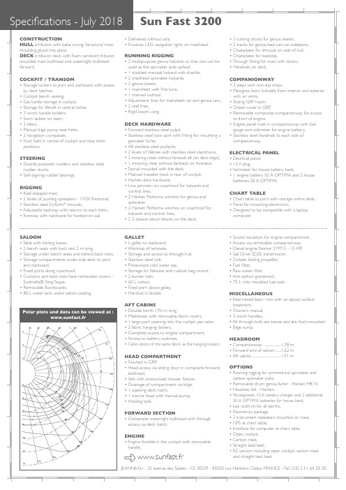
Specifications - July 2018CONSTRUCTION HULL : Infusion with balsa coring. Structural inner moulding glued into place.DECK : Infusion deck with foam sandwich Infusion moulded mast bulkhead and watertight bulkhead forward.COCKPIT / TRANSOM • S torage lockers to port and starboard with access by deck hatches, • C ockpit bench seating,• G as bottle storage in cockpit,• S torage for liferaft in central locker,• 3 winch handle holders,• S wim ladder on stern,• 2 tillers,• M anual bilge pump near helm,• 2 navigation compasses, • F oot hold in centre of cockpit and near helm positions.STEERING • D ouble polyester rudders and stainless steel rudder stocks, • S elf-aligning rudder bearings.RIGGING • K eel-stepped mast,• 2 levels of pushing spreaders - 19/20 fractional, • S tainless steel Dyform ® shrouds,• A djustable backstay with returns to each helm,• F orestay with hardware for hanked-on sail,• D elivered without sails,• T ricolour LED navigation lights on masthead.RUNNING RIGGING • 2 multipurpose genoa halyards so that one can be used as the spinnaker pole uphaul,• 1 doubled mainsail halyard with shackle,• 2 masthead spinnaker halyards,• 2 genoa sheets,• 1 mainsheet with fine tune,• 1 mainsail outhaul,• A djustment lines for mainsheet car and genoa cars,• 2 reef lines,• R igid boom vang.DECK HARDWARE • F orward stainless steel pulpit,• S tainless steel bow sprit with fitting for mounting a gennaker furler,• A ft stainless steel pushpits,• 2 levels of lifelines with stainless steel stanchions,• 2 mooring cleats without fairleads aft (on deck edge),• 1 mooring cleat without fairleads on foredeck,• T oerail moulded with the deck, • M ainsail traveller track in rear of cockpit,• H arken deck hardware,• L ine jammers on coachroof for halyards and control lines,• 2 Harken Performa winches for genoa and spinnaker,• 2 Harken Performa winches on coachroof for halyards and control lines,• 2 3-sheave return blocks on the deck,• 2 turning blocks for genoa sheets,• 2 tracks for genoa lead cars on sidedecks,• C hainplates for shrouds on side of hull,• C hainplates for backstay,• T hrough fitting for mast with blocks,• H andrails on PANIONWAY • 3 steps with non-slip strips,• P lexiglass door lockable from interior and exterior with air vents,• S liding GRP hatch,• O cean cover in GRP ,• R emovable composite companionway for access to front of engine,• E ngine panel inset in companionway with fuel gauge and voltmeter for engine battery,• S tainless steel handrails to each side of companionway.ELECTRICAL PANEL • E lectrical panel,• 12 V plug,• V oltmeter for house battery bank,• 1 engine battery 50 A OPTIMA and 2 house batteries 50 A OPTIMA.CHART TABLE • C hart table to port with storage within desk, • P anel for mounting electronics,• D esigned to be compatible with a laptop computer.SALOON • T able with folding leaves,• 2 bench seats with back rest 2 m long, • S torage under bench seats and behind back rests, • S torage compartments under side deck to port and starboard,• F ixed ports along coachroof,• C ushions and back rests have removable covers - Sunbrella® Sling T aupe,• R emovable floorboards,• 80 L water tank under saloon seating.GALLEY • L -galley to starboard,• W orktop of laminate,• S torage and access to through-hull,• S tainless steel sink,• P ressurised cold water tap,• S torage for flatware and rubbish bag mount,• 2 burner hob,• 60 L icebox, • F ixed port above galley,• H andrail in facade.AFT CABINS • D ouble berth 1,96 m long,• M attresses with removable fabric covers,• 1 large port opening into the cockpit per cabin,• 2 fabric hanging lockers,• C omplete access to engine compartment,• A ccess to battery switches,• C abin doors of the same fabric as the hanging lockers.HEAD COMPARTMENT • F inished in GRP ,• H ead access via sliding door in composite forward bulkhead,• S ink with pressurised shower fixture,• D rainage of compartment via bilge,• 1 opening deck hatch,• 1 marine head with manual pump,• H olding tank.FORWARD SECTION • C omposite watertight bulkhead with through access via deck hatch.ENGINE • E ngine throttle in the cockpit with removable handle,• S ound insulation for engine compartment,• A ccess via removable companionway,• D iesel engine Yanmar 2YM15 - 15 HP ,• S ail Drive SD20 transmission,• 2-blade folding propeller,• F uel filter,• R aw water filter,• A nti-siphon gooseneck,• 75 L roto moulded fuel tank.MISCELLANEOUS • K eel mixed lead / iron with an epoxy surface treatment,• O wner’s manual,• 3 winch handles,• A ll through-hulls are bonze and are flush-mounted • B ilge sump.HEADROOM • Companionway: .....................1,78 m • Forward end of saloon: ......1,62 m • Aft cabins: ..................................1,91 m OPTIONS • R unning rigging for symmetrical spinnaker and carbon spinnaker pole,• R emovable drum genoa furler - Harken MK IV,• H eadstay foil - Harken,• S horepower, 10 A battery charger and 2 additional 50 A OPTIMA batteries for house bank ,• L ee cloth kit for all berths,• E lectronics package,• 2 instrument repeaters mounted on mast,• G PS at chart table,• I nterface for computer at chart table,• O pen cockpit, • C arbon mast, • S traight lead keel,• R 2 version including open cockpit, carbon mast and straight lead keel. 10 20 30 40 5060708090100110120130140150160170 2 4 6 8101214 4 6 81012 2 4 6 4 6 810121416202530 4 6 810121416202530Polar plots and data can be viewed at : www.sunfast.fr www.sunfast.frSun Fast 3200JEANNEAU - 32 avenue des Sables - CS 30529 - 85505 Les Herbiers Cédex FRANCE - Tél. (33) 2 51 64 20 20。
海盗船缆系(25层)aglia布说明書说明书
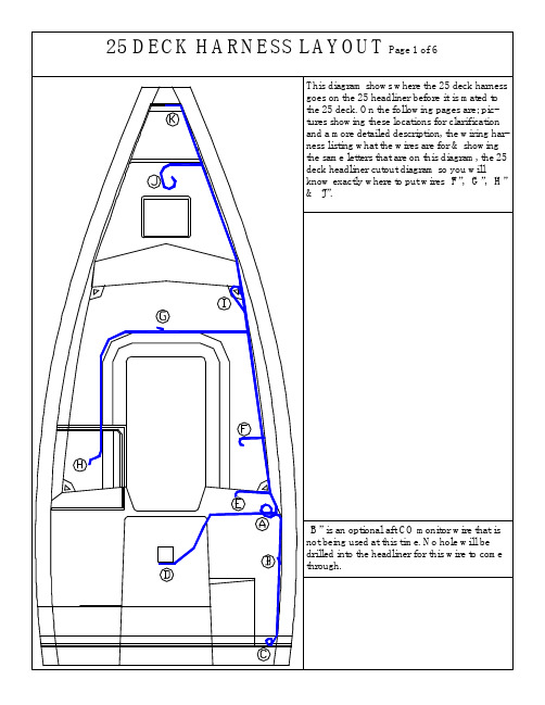
This diagram shows where the 25 deck harness goes on the 25 headliner before it is mated to the 25 deck. On the following pages are; pic-tures showing these locations for clarification and a more detailed description, the wiring har-ness listing what the wires are for & showing the same letters that are on this diagram, the 25 deck headliner cutout diagram so you will know exactly where to put wires “F”, “G”, “H” & “J”.“B” is an optional aft CO monitor wire that is not being used at this time. No hole will be drilled into the headliner for this wire to come through.HUNTER 25 DC DECK HARNESS 12/3/2004WIRE# GAUGE COLOR LENGTH FUNCTION1 16 BLUE 210" GALLEY&FWD LIGHTS2 16 YELLOW 210" GALLEY&FWD LIGHTS NEG.3 16 BLUE 244" M-C&PORT LIGHTS4 16 YELLOW 244" M-C&PORT LIGHTS NEG.5 16 BLUE 91" AFT CABIN LIGHTS6 16 YELLOW 88" AFT CABIN LIGHTS NEG.7 16 GRAY/WHITE 215" BOW LIGHT8 16 YELLOW 212" BOW LIGHT NEG.9 16 GRAY/YELLOW 249" STERN LT10 16 YELLOW 246" STERN LT NEG.11 16 GRAY/RED 143" ANCHOR LT12 16 GRAY/GREEN 143" STEAMING LT13 16 YELLOW 140" MAST LTS NEG.14 16 RED/BLUE 123" FWD CO ALARM15 16 YELLOW 120" FWD CO ALARM NEG.16 16 RED/BLUE 67" AFT CO ALARM17 16 YELLOW 64" AFT CO ALARM NEG.18 12 BROWN/ORG 134" BILGE PUMP(AUTO)19 12 BROWN/RED 207" BILGE PUMP(MANUAL)20 12 YELLOW 204" BILGE PUMP NEG.21 8 RED 76" PANEL POWER22 8 YELLOW 146" PANEL NEG.23 16 YELLOW 15" BILGE PUMP INDICATOR NEG.24 12 TAN 85" BILGE PUMP POWER25 8 ORANGE/RED 82" DC PANEL26 16 BLUE 3" FWD CABIN LIGHTS“A” GOING TO “C”GOING TO “D”“E”NOTE: A 2” HOLE WILL BE DRILLED HERE MAKESURE HARNESS IS OUT OF THE WAY“A”“D”“C”“B”“F”“E”LOOK AT DECK CUTOUT DIAGRAM FOR EXACT LOCATION OF “F”“I”“G”LOOK AT DECK CUTOUTDIAGRAM FOR EXACT LOCATION OF “G”“H”“H”“J”LOOK AT DECK CUTOUT DIAGRAM FOR EXACT LOCATION OF “H”LOOK AT DECK CUTOUT DIAGRAM FOR EXACT LOCATION OF “J”“K”Breaker Panel LocationLocation Of Mast PlugLocation for compasslight wire。
海盗船舶产品:冷冻盒跟踪翻转说明书

1 1 Rub Rail Keeper - Transom22' 308080 2 2 Rub Rail Keeper - Port and Starboard Sides34' each 308080 3 176 Rub Rail Keeper Fasteners#10 x 1 1/2" FH461330 4 1 Stainless Rub Rail 78' 308138 5148Stainless Fasteners# 8 x 3/4" OH4659301.VERY HOT - USE CAUTION : For this procedure you will need three people. Using heat resistant gloves, retrieve the 22' piece of rub rail keeper from the hot box and quickly place the keeper over the boat flange. Fig. 22.Have the person who is going to tape the keeper in place center the keeper using the center of the transom boat flange and the center mark on the rub rail keeper as a guide. Place the keeper over the flange, the other two people will wrap it around both sides. Re-member the long edge of the keeper goes on top.3.While the two people hold the keeper in place the other will tape the keeper into place using 3" white Polykin Tape. (Fig. 4 & 5)356 SOP RUB RAIL INSTALLATIONpage 1 of 3Heating The Rub Rail Keeper:Before pinning the flange, mark the center of the 22' piece of rub rail keeper then place it into the hot box for 3 to3 1/2 hours to soften before installing.Revision Dates:Expected Time: 165 minFig. 1Before retrieving the rub rail keeper from the hot tank check around the deck flange for holes, voids or chips in the seal. If there are any seal them using 5200 white caulk. (Fig. 1)Also make sure all fasteners have been broken off flush to the flange.Fig. 2Fig. 4Fig. 5Fig. 3 StarboardPortLong edge at top of flangeNOTE: Close observation of the rubrail keeper will show that it is not symmetrical. The long edge of the flange will go on top. Orientate the rubrail while it is in the hotbox to facilitate putting the hot piece on the boat in a timely manner.Installation And Securing Of The Rub Rail Keeper : Please read all the instructions below before proceedingFig. 7Fig. 9 HullFig. 8 Deck Fig. 6Fig. 10Fig. 11Installation Of Stainless Rub Rail1.Starting on the port side and at the center of the transom, in-stall the stainless rub rail by placing it into the grooves of the keeper.ing a 1/8" drill bit, drill through the predrilled holes in the rail and into the keeper. Secure first two holes using desig-nated fasteners. Fig. 123.For the transom area, two people will be needed. One person will twist the rail using vice grips or channel locks forming the rail to fit the curves of the keeper, while the second person will drill and secure the rail. Fig. 134.Using a rubber mallet, hammer the rail to close the gaps be-tween the rail and the keeper. Fig. 14 & 155.Repeat this process for the starboard transom side. Fig.316After transom is installed, continue drilling and securing the rail down both sides of the boat. Fig. 326.Cut off excess rail even with the bow of the boat. Fig. 17Fig. 16Fig. 12Fig. 13Fig. 14Fig. 15Fig. 17356 SOP RUB RAIL INSTALLATIONpage 3 of 3。
海盗船长 Kayak 用户手册说明书

Usage
Sit in the cockpit area of the kayak, centered in the provided seat area. Using the foot braces, secure your feet so your knees are bent and feel sturdy. Paddle with your arms evenly apart at a medium speed switching back and forth from one side to the other. The paddle should enter the water around your shins and pull out of the water around your hips.
• If your watercraft has been exposed to hot sunlight, it is recommended to splash water on the hull to cool the hot surface before it comes in direct contact with your skin. This should also be done for any paddles you may have.
KAYAK OWNER’S MANUAL
Transporห้องสมุดไป่ตู้ation
Use caution when transporting your kayak. Be sure to tie down your kayak,
but do not overtighten the straps.
Storage
迈利戈Elite Pro mini用户手册说明书
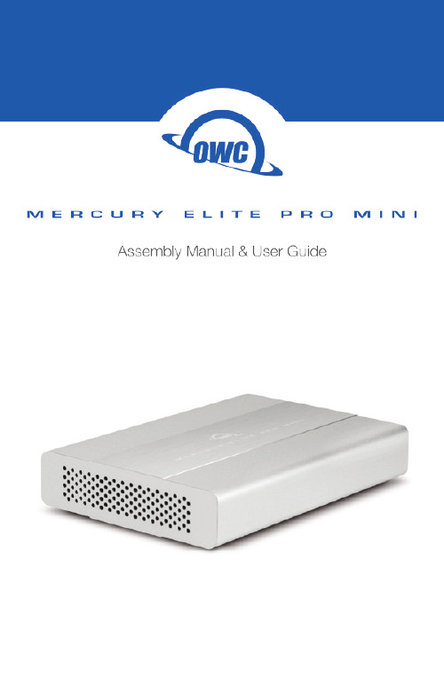
TABLE OF CONTENTSINTRODUCTION (1)1.1 Minimum System Requirements1.2 Package Contents1.3 About This Manual1.4 Rear View1.4.1 Rear Features1.5 Usage NotesDEVICE SETUP (4)2.1 Quick Start2.2 AssemblySUPPORT RESOURCES (9)3.1 Formatting3.2 About Data Backup3.3 Troubleshooting3.4 Contacting Technical Support1.2 Package Contents* USB 3.1 Gen 1 ports are compatible with USB 2.0 connections.** FireWire cable included only with USB 3.0 / FireWire model.*** eSATA cable included only with USB 3.0 / eSATA model.Not Pictured: packet with four Phillips screwsRequired Tools: Phillips PH2 driver1.3 About This ManualThe images and descriptions may vary slightly between this manual and the unit shipped. Functions and features may change depending on the firmware version. Please visit the product web page for the most recent specifications.INTRODUCTIONApple Mac Requirements• FireWire 800: OS X 10.2 or later• USB 3.1 Gen 1: OS X 10.6 or later *• eSATA: OS X 10.3 or later PC Requirements • FireWire 800: Windows® XP or later • U SB 3.1 Gen 1: Windows XP or later *•eSATA: Windows XP or later1.1 Minimum System RequirementsFireWire 800 (1394b)9-9 pin cable **Mercury Elite Pro miniUSB 3.1 Gen 1 cable (Standard-A to Micro-B)eSATA Cable***1.4 Rear ViewThe Mercury Elite Pro mini comes in two port configurations :USB 3.1 Gen 1 / FireWire 800USB 3.1 Gen 1 / eSATA1.4.1 Rear Features1. USB 3.1 Gen 1 port — Attach the included USB 3.1 Gen 1 (Standard-A to Micro-B) cable here.2. FireWire 800 ports — Attach the included FireWire 800 cable here. Use the other FireWire 800 port to daisy-chain other FireWire 800 devices. NOTE: Any daisy-chained device must use its own power supply. The Mercury Elite Pro mini cannot bus-power other devices.3. eSATA port — Attach the included eSATA cable here. NOTE: The connector is keyed to use one specific orientation. If the connector does not go in smoothly, do not force it. Flip it over and re-insert it.4. ON|OFF switch — Power the Mercury Elite Pro mini on and off here.5. DC IN — Connect the optional 5V power adapter here (sold separately).112344551.5 Usage Notes• Use only one interface (USB, FireWire, or eSATA) at a time.• The Mercury Elite Pro mini is designed to receive all needed power through the USB or FireWire cable, therefore a separate power adapter is not necessary and not included. When using eSATA or other scenarios that require external power, an optional 5V power adapter is available. See Section 3.4 to contact OWC support for more information.• If the Mercury Elite Pro mini is daisy-chained to another FireWire device instead of being connected directly to a computer, you must use the optional 5V power adapter. Attempting to bus-power the Mercury Elite Pro mini using the FireWire port of another device is not recommended; this could cause damage to one or both devices.• Even if the optional 5V power adapter is not connected, the ON|OFF switch must be in the “ON” position to use the Mercury Elite Pro mini.• If you are connected via FireWire and running OS X version 10.9 or later, you may run into issues when attempting to sleep this drive or wake from sleep. The easiest way to avoid this issue is to use the USB or eSATA connection instead.• For the safe removal of your drive and to ensure that no data is lost, always eject or unmount corresponding disk from your OS before powering off.OS X Eject Methods:• Drag the icon for the disk to the trash can;• Right-click the disk icon on the Desktop, then click “Eject”.• Highlight the disk icon on the Desktop and press Command-E.Windows Eject Method:1. Go to the System Tray (located in the lower right corner of yourscreen). Click on the “Eject” icon (a small green arrow over ahardware image).2. A message appears detailing the devices that the “Eject” iconcontrols, click this message prompt.3. You will then see a message that says, “Safe to RemoveHardware.” It is now safe to disconnect the Mercury Elite Pro fromthe computer.2.1 Quick StartIf you purchased the OWC Mercury Elite Pro mini as an empty enclosure, proceed to Section 2.2 for assembly tips. If you purchased the enclosure with a drive already installed, the OWC Drive Guide formatting utility has been installed to assist with the setup. Follow the steps below to use the OWC Drive Guide to format the drive for Mac (OS X 10.4 and later) or Windows (XP and later).1. Connect the Mercury Elite Pro mini to your computer using the proper cable. If you prefer to use a different formatting utility, do so at this time and skip the rest of these instructions.2. Your drive will appear as “OWC SETUP”. Double-click the disk icon.3. Double-click the OWC Drive Guide application.4. Follow the instructions to complete the formatting process.5. Once the formatting is finished the drive is ready to use.2.2 AssemblyThe Mercury Elite Pro mini comes in two configurations. As shown in Section 1.4, one model provides a single USB 3.1 Gen 1 port and two FireWire 800 ports, and the other model provides one USB 3.1 Gen 1 port and one eSATA port. The pictures in the following assembly instructions show the latter model, but the process is exactly the same for both models.NOTICE: If your Mercury Elite Pro mini was purchased with a drive already installed, opening the case will void your warranty . Once thewarranty period expires, if you would like to open the case at thattime, you may do so.DEVICE SETUP1. Use a Phillips PH2 driver to remove the two screws at the rear of the enclosure (circled below in red).2. Tilt the Mercury Elite Pro mini to allow the back plate to fall free, as shown below. If the back plate does not fall free, you can push gently on the ON|OFF switch to disengage the ports from the back plate.3. Gently push on the inner chassisthat was exposed by removing theback plate. The inner chassis shouldslide out of the outer enclosure.Once there is enough room at thefront, as shown to the left, you canpull on the front of the inner chassisto remove it fully.4. Once the inner chassis has been removed from the outer enclosure, note the SATA connector, highlighted in yellow. There are also four screw holes highlighted in red — two through the metal on the right and two through the green circuit board on the left.5. Place the drive in the inner chassis as shown below. Slide the drive into the SATA connector on the circuit board, making sure the drive is fully seated before proceeding.6. Use one hand to hold the drive in place, then turn over the inner chassis. There are four screw holes on the bottom of the inner chassis (circled in red below).7. Insert the four included screws into the screw holes, then use a Phillips driver to fasten the drive to the inner chassis (shown below). When this is done, turn the inner chassis over.8. Slide the inner chassis back into the outerenclosure. Note that the inner chassis can slideinto either end of the outer enclosure, but therails on one end of the outer chassis are notched,as shown to the left. This allows the back plateto sit flush when attached.9. Attach the back plate as shown below and use a Phillips driver to re-affix the two screws that you removed in Step 1.3.1 FormattingTo view formatting tips, visit: /format3.2 About Data BackupTo ensure your files are protected and to prevent data loss, we strongly suggest that you keep two copies of your data: one copy on your Mercury Elite Pro mini and a second copy on your internal drive or another storage medium, such as an optical backup, or on a second external storage unit. Any data loss or corruption while using the Mercury Elite Pro mini is the sole responsibility of the user, and under no circumstances may OWC, its parents, partners, and affiliates be held liable for loss of the use of data including compensation of any kind or recovery of the data.3.3 TroubleshootingBegin your troubleshooting by verifying that both ends of your cable are properly plugged into the computer and the Mercury Elite Pro mini. If the drive is still not working properly, try connecting to another interface such as the USB connection and see if the device works properly. You can also connect the Mercury Elite Pro mini to a different computer. If problems persist, please contact technical support or visit: /faqHours:8am to 8pm (CT) Monday - Friday 9am to 4pm (CT) SaturdayTelephone:(866) 692-7100 (North America) +1 (815) 338-4751 (International)Live Chat:/supportEmail:/support3.4 Contacting Technical Support SUPPORT RESOURCES9Copyright 2016 OWC. All Rights Reserved.OWC’s Limited Warranty is not transferable and subject to limitations.Changes:The material in this document is for information purposes only and subject to change without notice. While reasonable efforts have been made in the preparation of this document to assure its accuracy, OWC and its officers and employees assume no liability resulting from errors or omissions in this document, or from the use of the information contained herein. OWC reserves the right to make changes or revisions in the product design or the product manual without reservation and without obligation to notify any person of such revisions and changes.FCC Statement:Warning! Modifications not authorized by the manufacturer may void the user’s authority to operate this device.NOTE: This equipment has been tested and found to comply with the limits for a Class A digital device, pursuant to Part 15 of the FCC Rules. These limits are designed to provide reasonable protection against harmful interference when the equipment is operated in a commercial environment. This equipment generates, uses, and can radiate radio frequency energy and, if not installed and used in accordance with the instruction manual, may cause harmful interference with radio communications. Operation of this equipment in a residential area is likely to cause harmful interference, in which case the user will be required to correct the interference at his own expense.NOTE: This equipment has been tested and found to comply with the limits for a Class B digital device, pursuant to Part 15 of the FCC Rules. These limits are designed to provide reasonable protection against harmful interference in a residential installation. This equipment generates, uses and can radiate radio frequency energy and, if not installed and used in accordance with the instructions, may cause harmful interference to radio communications. However, there is no guarantee that interference will not occur in a particular installation. If this equipment does cause harmful interference with radio or television reception, which can be determined by turning the equipment off and on, the user is encouraged to try to correct the interference by one or more of the following measures:• Reorient or relocate the receiving antenna.• Increase the separation between the equipment and receiver.• Connect the equipment to an outlet on a circuit different from that to which the receiver is connected.Health And Safety Precautions:• Use proper anti-static precautions while performing the installation of your hard drives into this drive enclosure. Failure to do so can cause damage to your drive mechanisms and/or the hard drive enclosure.• Read this user guide carefully and follow the correct procedures when setting up the device.• Do not attempt to modify the device. To avoid any risk of electrical shock, fire, short-circuiting or dangerous emissions, never insert any metallic object into the device. If it appears to be malfunctioning, contact OWC technical support.• Never expose your device to rain, or use it near water or in damp or wet conditions. Never place objects containing liquids on the drive, as they may spill into its openings. Doing so increases the risk of electrical shock, short-circuiting, fire or personal injury.General Use Precautions:• To avoid damage, do not expose the device to temperatures outside the range -40°F to 185°F (40°C to 85°C)• Always unplug the device from the electrical outlet if there is a risk of lightning or if it will be unused for an extended period of time. Otherwise, there is an increased risk of electrical shock, short-circuiting or fire.• Do not use the device near other electrical appliances such as televisions, radios or speakers. Doing so may cause interference which will adversely affect the operation of the other products.• Do not place the device near sources of magnetic interference, such as computer displays, televisions or speakers. Magnetic interference can affect the operation and stability of hard drives.• Do not place heavy objects on top of the device.• Protect your device from excessive exposure to dust during use or storage. Dust can build up inside the device, increasing the risk of damage or malfunction.• Do not block any ventilation openings on the device. These help to keep the device cool during operation. Blocking the ventilation openings may cause damage to the device and cause an increased risk of short-circuiting or fire.• For up-to-date product and warranty information, please visit the product web page.Copyrights and Trademarks:All rights reserved. No part of this publication may be reproduced, stored in a retrieval system, or transmit-ted in any form or by any means, electronic, mechanical, photocopying, recording or otherwise, without the prior written consent of OWC.© 2016, OWC. All Rights Reserved.OWC is a trademark of New Concepts Development Corporation, registered in the U.S. Patent and Trade-mark Office and/or in Canada. The OWC logo is a trademark of New Concepts Development Corporation. Apple, Firewire, Mac, and OS X are trademarks of Apple Inc., registered in the United States and other countries. Windows is a registered trademark of Microsoft Corporation in the United States and other countries. Other marks may be the trademark or registered trademark property of their owners.R6 05/12/16 DM OWCMANMEPMU3AM。
海盗国防士UPS ED04A0308600000000说明书
Eaton ED04A0308600000000Eaton 93PS Marine UPS, 40 kVA, 40 kW, 40 kW frame/StaticSwitch, 2 x 20 kW Power module, 440 V input TF, 400V output,Internal Maintenance Bypass SwitchEaton 93PS Marine UPS ED04A0308600000000850 mm 2150 mm750 mm 427 kg1 year CE MarkedRoHS CompliantCBIEC/EN 62040-2 IEC/EN 62040-1EN 62040-393PS-M-40(40)-40-MBS-8-440/-Product Name Catalog NumberProduct Length/Depth Product HeightProduct Width Product WeightWarranty CompliancesCertifications Model Code60 Hz50 Hz140 kWTower96 %TowerFixed connection 380 V415 V50 HzHardwiredIP23Free standing model Yes380 VGray Eaton 93PS Marine UPS DNV GL type approvalEaton 93PS Marine UPS 8-40 kW Declaration of conformitySecondary Frequency Max Input frequency - min Output power factor WattageForm factorOverall efficiencyMounting MethodInput connectionInput voltage - minOutput voltage - max Secondary Frequency Min External battery connection Degree of Protection Construction typeInternal maintenance bypass Output voltage - minColorTopology Certyfikaty Compliance informationOnline/Double-conversionNumber of output connections fixed connection1kVA rating40 kVAEfficiency (eco-mode)99 %Runtime at half load0 minImproved efficiency modeESS with VMMSInput nominal voltage400V default (380/400/415V)Input frequency - max60 HzNumber Of Output Connections With Protective Contact (Schuko)Input voltage - max415 VPhase (output)3Integrated functionalityNetwork MangementModularAuto shutdown functionYesPotential free switch contactYesApplicationMarineInternal battery includedNoPhase (input)3Package contentsUPSQuickstart guideSafety instructionsOutput effective power40000 WFeed typeACVoltage distortion output (linear load) - max 1.5 %Hot-swappable power modulesYesOutput apparent power40000 VAParallelableParallel for capacity and redundancyOutput frequency50 Hz (50/60 Hz programmable)Primary frequency - min50 HzAudible alarmsYesType Of InterfaceOtherTypeUPSTransition time for full load0 sBattery charger typeABM technologyRuntime at full load0 minSnmpYesPrimary frequency - max60 HzEaton Corporation plc Eaton House30 Pembroke Road Dublin 4, Ireland © 2023 Eaton. Wszelkie prawa zastrzeżone.Eaton is a registered trademark.All other trademarks areproperty of their respectiveowners./socialmedia。
海盗船长 Pull-pin 可inflatable PFD 闪光灯说明书

A Cheltoncation lighting to USCG requirements for 6 hours > Pull-pin activation: Automatically activates when PFD inflates or if manually pulled > Adjustable flash shield for optimum eye protection > Pull-pin lanyard clips to bottom of inflation chamber > Light test feature with “Test Key” to ensure readiness–can be tested many times > Easy to mount–fits on inflation tube via O Ring which will not damage inflation tube,
(recommended replacement 5 years from date of purchase–write month/year of replacement date on case at time of purchase) > Operating life–approximately 8 hours continuous at -20°C (-4°F)
阿尔法迪纳诺 AlphaMiniCourse Mk2 航海仪说明书
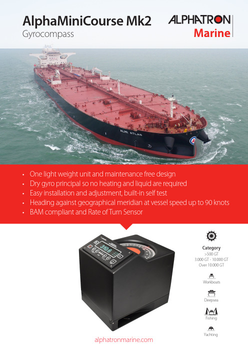
Category>500 GT3.000 GT - 10.000 GT Over 10.000 GTWorkboatsDeepseaFishingYachtingThe AlphaMiniCourse Mk2 is designed to meet the needs of the marine market. Highly accurate performance derived from the aerospace industry, combined with a ruggedized construction in order to cope with the most severe circumstances at sea. The AlphaMiniCourse Mk2 has a monoblock design. The compass outer casing has a window on top for easy compass reading and if required, the control unit can be mounted at maximum 100 meters from the main gyro.Maintenance freeThe AlphaMiniCourse Mk2 is a maintenance-free gyro compass with an astonishing reliability index (Failure-Free Operation Period)set at 60.000 hours.FeaturesIn controlThe control unit, integrated within the AlphaMiniCourse Mk2, provides all the functions and indicatorsnecessary to power up, control and operate the AlphaMiniCourse Mk2. The control unit displays allinformation on an integrated display.There may be applications where it ispreferred to install the Control Unit at some distance from the gyro compass. For this purpose we offer a bracket for (e.g. ECR, bridge) Control Unit including a 2 meter long 3x2x0,5mm cable which covers the distance between the Control Unit and the terminals. The Control Unit can be used up to 100 meter from master compass to control the gyro remotely.Control unitBracket with control unit• Operating mode, alarms and status information • Heading against the geographical meridian at the • Latitude up to 89° South and 89° Northvessel speed up to 90 knotsUpon installation the gyro will settle fast with the pre-set heading. This takesonly approx. 45 minutes.The AlphaMiniCourse Mk2 is a self-contained precision navigation instrumentcapable of supplying heading reference information simultaneously to a widerange of equipment located on board the vessel. T o support this wide rangeof equipment, the AlphaMiniCourse Mk2 can supply heading informationsimultaneously through multiple channels using any of the commontransmission formats.On a typical vessel heading information is used among others by• Autopilot• Radars• Radio direction finder • Course plotter and course recorder • Satellite communication systems • Satellite televisionHeadingBackward Running mode can be activated when a AlphaMiniCourse Mk2 is installed on a ferry.The data will contain the heading rotated by 180 degrees.AlphaLine RepeaterThe AlphaLine Repeater displays range provides a heading repeater connectable to gyro, magnetic and G-002752G-002750G-002742G-002744Mounting bracketThe mounting bracket for the repeater compass has a gimbal ring to support the repeater compass horizontally when the ship is rolling and pitching.Repeater compassThe repeater compass receives and displays the ship’s heading signaltransmitted from the master compass. The case is made of aluminium, thus corrosion free and has a waterproof construction, suitable for open deck installation.Azimuth circleAstronomical observations can be made with the mirror and the slit located on the azimuth circle, and measurements of objects with the lubber’s line and the slit.AccessoiresPedestalThe repeater stand (height of 1170 mm) can be used when a repeater compass is installed on the deck.Junction boxThis junction box is made built-in with the drive circuit of the compass motor. With this we succeeded in minimizing the radiated interference (EMI) which may cause malfunction to surrounding equipment.G-005443G-005442G-005445G-005444Mounting kitsDifferent types of brackets for the control unit are available for the AlphaMiniCourse Mk2.G-004539G-003939A range of accessoires are available for the AlphaMiniCourse Mk2.All data of each gyro or external heading is displayed on the controller and will also becompared. Each gyrocompass may be individually switched on or off from the controller. Multiple users can be connected to the Digital Selector Switch directly, making this new Alphatron product a true asset to the international maritime market.Features• Fully redundant with a selectable manual override• Input for up to 4 compasses or other external heading indicators (e.g. magnetic compass), isolated • Comparison of heading from several Gyrocompasses or other external heading indicators • Multiple serial in and outputs:• Serial data transfer rate 4800; 9600; 19200; 38400 baud • Failure: NO relay/ NC relay• Status/Alarm: Ready - NO relay/ NC relay• Serial data transfer frequency; 1Hz (1sec); 10 Hz (100msec); 20 Hz (50msec)• S-type heading:Channel A: 1 х RS232; 4 x RS422Channel B: 1 х RS232; 4 x RS422Channel C: 1 х RS232; 4 x RS422Channel D: 1 х RS232; 4 x RS4222x step-by-step, 6 steps/degree (24V TTL level)Update 6°/s, 12° or unlimited286 m m (11.26 i n )305 mm (12.01 in)Main unitG-007513Weight 12.5 kg (27.56 lbs)286 m m (11.26 i n )240 mm (9.45 in)Foundation example (yard supply)346 mm (16.62 in)70 mm (2.76 in)70 mm (2.76 in)196 mm (7.72 in)5 m m (0.2 i n )5 m m (0.2 i n )55 m m (2.17 i n )5 mm (0.2 in) 50 mm (1.97 in)173 mm (6.81 in)173 mm 6.81 in)47 mm (1.85 in)207 mm (8.15 in)92 mm (3.62 in) 346 mm (16.62 in)96,5 m m (3.8 i n )96,5 m m (3.8 i n )⌀ 252 mm280 m m (11.02 i n )16 mm (0.63 in)3x ⌀9 mm130°M6Or earth bold M6x20welded on foundationSystem diagram & Tech SpecsP O W E RRE A D YF A I L U R ED IG I T A L S E L E C T O R S W I T C HOutputs:Heading 16x RS422Heading 4x RS232StepperAlarm drycontacts & NMEA Uninterruptible 24V DC GPS & LOG (optional) inputEXT headingRCU output RCU output24V DC 24V DCSpecificationsCenters of Excellence JRC/Alphatron Marine B.V. Schaardijk 233063 NH Rotterdam The Netherlands+31 10 453 4000JRC/ProNav ASHovlandsveien 524374 EgersundNorway+47 5146 4300JRC South East Asia100 Pasir Panjang118518 SingaporeSingapore+65 6863 0335JRC Americas1205 Butler RoadTX 77573 HoustonUnited States of America+1 281 271 4600JRC T okyo1-7-32 T atsumi, Koto-ku T okyo 135-0053 Japan+81 3 5534 7800JRC ShanghaiFloor 9-A Building C2,Shanghai International Trade Center,1599 New Jinqiao Road,Pudong, Shanghai, China 201206+86-21-2024-0607© All rights reserved, JRC/AM -20.06/207/3Product and/or specifications could change without notice。
游艇使用说明书-2012.05.19-
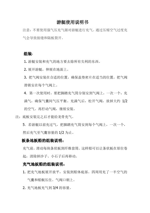
游艇使用说明书注意:不要使用强气压充气源对游艇进行充气。
通过压缩空气过度充气会导致接缝和隔板裂开。
组装:1. 游艇安装和充气的地方要去除所有尖利的东西。
2. 展开游艇,伸展在地面上。
3. 把气阀安装在合适的位置,确保盖垫密片在适当的位置,把气阀滑锁安在每个气阀上。
4.第一次使用时,要把脚踏充气筒分别安到气阀上,一次一个,充满气,确保气囊间气压平衡。
充满气后,松开气阀,放掉大约1/2的空气。
再拧动气阀,继续安装。
注:底板安装完之后才能给龙骨充气。
5.若游艇以前充过气,把脚踏充气筒安到每个气阀上,一次一个,然后充气至气囊容量的1/2为止。
板条地板船的组装说明:充气前,滑动每块条状板到纤维套筒。
这样船可以让条状板在原位卷起,清除掉沙子、小石子后再移动。
充气地板船的组装说明:1.把充气地板展开放平,安装到船体底部。
四周用充了一半空气的气囊和船艉压住。
气阀口朝上。
2.充气地板充气到3/4的容量。
3.气囊充满。
4.充气地板充满。
5.龙骨充满。
木地板船的组装说明注:确保底板的数块木板的面朝上。
1. 安装第一块板到船的弓形处。
2. 安装第四块板到船的艉板处。
3. 安装第二块板到第一块板处。
4. 安装第三块板到第二块和第四块板处并向下压直到平了为止。
船边接连处的安装1.气室空气充到容量的3/4.2.滑动船桨(a)在底部提升底板。
(b)在平坦的表面安上船边连接物。
(c)在船的另一边重复相同的步骤。
3.安装座位4.把脚踏充气筒安到每个阀门上,充满气,同时保持气囊内的空气平衡。
不要一次完全充满气囊的容量。
安装气阀帽。
5.充气龙骨,安装气阀帽。
充气船的装配第一次使用时,要把脚踏充气筒分别安到气阀上,一次一个,充满气,确保气囊间气压平衡。
用测压仪检查气压。
拆卸存放船艇之前,将船艇清洗并晾干,清除游艇上全部杂物。
1. 松开所有空气阀以放气。
2. 拿掉座位。
3. 从底板拿掉船边连接物。
4. 提高中间的底板,从接口拆开。
拿掉底板,最后拿掉弓形部分和艉板。
AlphaMidiCourse Mk2 海洋航海指南仪说明书
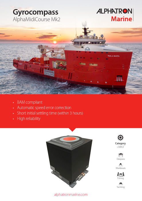
• BAM compliant• Automatic speed error correction• Short initial settling time (within 3 hours) • High reliabilityGyrocompassAlphaMidiCourse Mk2Category>500GTYachtingFeaturesThe AlphaMidiCourse Mk2 is a reliable, type-approved gyrocompass for merchant vessels. There is a standard and a HSC version available. This gyrocompass is easy to install and requires little maintenance since there’s no fluid inside. Alphatron Marine can also supply all peripheral equipment such as repeaters and converters to ensure compatibility with existing installations.The AlphaMidiCourse Mk2 is a self-contained precisionnavigation instrument capable of supplying headingreference information to a wide range of equipmentlocated on board the vessel. T o support this wide rangeof equipment, the AlphaMidiCourse can supply headinginformation through multiple channels using commontransmission formats. On a typical vessel headinginformation is used byMaster CompassThe AlphaMidiCourse Mk2 provides heading data against the geographical meridian (latitude up to 70°) at vessel speeds up to 50 knots in standard version and 70 knots in HSC version. Roll and pitch angles up to maximum ± 45°.• Autopilot• Radars• Electronic chart systems• Satellite communication systems• Satellite television• AISControl unitThe control unit, supplied with the AlphaMidiCourse MK2, provides all the functions and indicators necessary to power up, control and operate the AlphaMidiCourse MK2. The control unit displays all information on an integrated display which can show the following information:The control unit is used for connecting it’s master compass but also to connect ships’ cabling, like power and data cable to aggregate all relevant data for input and output.• Heading in degrees from 0.0 to 359.9• Heading source• Latitude from 60S to 60N• Latitude from 70S to 70N HSC version • Speed in knots from 0 to 50• Speed in knots from 0 to 70 HSC version • Speed source • Steering source • Rate of Turn• Alarms and status information• Presence of power and readiness of gyro Depending on the class and the notation of the vessel more than one gyro compass might be required. The AlphaMidiCourse can be used as dual gyro when used with a manual switch. The DGC unit allows you to connect multiple control units.compass for operation.S e r i a l r e p e a t e r sS t e p r e p e a t e rA l a r m c o n t a c t 24V D C (s h i p s u p p l y )24V D C (e m e r g e n c y s u p p l y )B A M S(D )G P S N M E AS p e e d l o g N M E AS p e e d l o g p u l s eE x t e r n a l s e n s o r N M E AGyro compassDGC change over unitis a steering indicator and shows an extended scale that also provides an accurate analog representation of tenths of degrees.A l p h a L i n e R e p e a t e r sA l p h a H e a d i n g + I n d i c a t o rAdvanced gyro elementThe high precision dynamically tuned gyroscope and gimbal suspension is derived from aerospace technology and is now available to the marine industry.• Unique technology without annual servicing of gyrosphere • Very low RPM reduces wear, increasing life time• No oil change • Quick installationMicroproccesor control boardSensitive element GimbalPhantom ring Horizontal control board Shock absorbers This advanced compass repeater has an analog moving compass card and fixed line. The LCD information screen displays in 5-inch (horizontal and vertical),The AlphaMidiCourse Mk2 is fully compliance with IMO ResolutionMSC.302(87) and its Performance Standards for Bridge Alert Management system (BAM). It harmonizes the priority, classification, handling, distribution and presentation of alerts, meaning that the bridge team can devote its full attention to the safe operation of the ship and immediately identify any alert situation requiring action to maintain the safe operation of the ship.BAMSpendulum function enables the heading to be changed by 180 degrees.repeaters around the vessel at critical positions. The gyrocompass is typically located below decks as close as possible to the center of roll, pitch and yaw of the ship, minimizing errors caused by the ship’s motion. Repeaters are located at convenient places throughout the ship, such as at the helm for steering, in after steering for emergency steering, and other places. Bearing repeaters installed on the bridge wing used for taking bearings will likely be equipped with removable bearing and azimuth circles, and telescopic alidades, which allow one to sight a distant object and see its exact gyrocompass bearing.A range of accessoires are available for the AlphaMidiCourse Mk2.Mounting bracketThe mounting bracket for the repeater compass has a gimbal ring to support the repeater compass horizontally when the ship is rolling and pitching.Repeater compassThe repeater compass receives and displays the ship’s heading signaltransmitted from the master compass. The case is made of Glass fiber Reinforced Plastic (GRP), thuscorrosion free and has a waterproof construction, suitable for open deck installation.Azimuth circleAstronomical observations can be made with the mirror and the slit located on the azimuth circle, and measurements of objects with the lubber’s line and the slit.AccessoiresRepeater standThe repeater stand (height of 1330 mm) can be used when a repeater compass is installed on the deck.Data distributionThe NMEA distribution module is used when IEC61162 signals from a sensor must be distributed to multiple listeners. The system provides galvanic isolation between talker and listeners and between listeners to avoid problems when a listener is influencing the signal. Multiple NMEA modules can be daisy chained with each other, which allows you to create as many outputs as you want.G-002327G-002328G-002330G-002329G-0025720 to 50 knots / 70 knots HSC version Follow up speed >75°/sec Settling time within 3 hours Settle point accuracy <±0,3°Dynamic accuracy <±0,5°/secSettle point repeatability <±0,2°/sec Service life 35.000 hoursMaster CompassG-007517 (standard) / G-009186 (HSC)Weight 23 kg (50.7 lbs)438 mm(17.24 in)1x step; 24V DC, 6 steps/°4x serial data; RS422/485Serial data transfer rate;IEC61162-1/2 (4800/38400 bps)24V backup supplyFailure/alarm; NO relay/NC relay Power 24V DC, 70WControl unitWeight 7 kg (15.43 lbs)252 mm(9.92 in)DGC-01 (Double Gyro Compass change over unit)G-007740Weight 14.58 kg (32.14 lbs)InputsGPS, BAMS, Speed LOG (optional)3 connections, 3x RS422Serial data transfer rate:IEC61162-1 (4800 bps) or IEC61162-2 (38400 bps)Outputs18 connections, RS422Serial data transfer rate: IEC61162-1 (4800 bps) or IEC61162-2 (38400 bps)6 connections; 24V DC – 6 step/°Rate of Turn: 3x analogue 30,120, 300 °/minFailure / Alarm; NO relay/NC relay/ IEC61162-1:2016 (4800 bps)$--HEALC, $--HEHBT , $--HEALFPower supply24V DC, 250VA (Main) / 24V DC, 75VA (Battery)AccessoiresG-007517G-007740G-002327G-002328G-002329G-002330G-002572Changeover DGC-01serial dataBH repeater stand Azimuth circleIn the box4 display sizes availableAlarm signal loss (audible/visual)Indication; heading, magnetic or true Rate of Turn (ROT)IEC61162-1 serial port interfaceInput; DDC, ROT , HDT (default), HDG, HDM, THSAlphaLine displays (option)MFS-H5-inch (Horizontal)MFS-V5-inch (Vertical)MFM 6.5-inchMFL 8.4-inch180 mm (7.09 in)96 mm (3.78 in)160 mm (6.30 in)180 mm (7.09 in)180 mm (7.09 in)240 mm (9.45 in)96 mm (3.78 in)180 mm (7.09 in)G-009186• •••••SpecificationsIEC Standard 62288 (2014): Maritime navigation and radiocommunication equipment and systems – Presentation of navigation-related information on shipborne navigational displays – General requirements, methods of testing and required test results;IEC Standard 60945 (2002) incl./Corr. 1 (2008): Maritime navigation and radio communication equipment and systems - General requirements - Methods of testing and required test results;IEC 61162 series:IEC 61162-1 (2016)IEC 61162-2 ed1.0 (1998-09)IEC-62923-1:2018: Maritime navigation and radiocommunication equip-ment and systems - Bridge alert management - Part 1: Operational and performance requirements, methods of testing and required test results IEC-62923-2:2018: Maritime navigation and radiocommunication equip-ment and systems - Bridge alert management - Part 2: Alert and cluster identifiers and other additional featuresMarine Equipment Directive 2014/90/EU or Wheelmark approved.Regulations V/18, Approval, surveys and performance standards of navigational systems and equipment and voyage data recorder;Regulations V/19, Carriage requirements for shipborne navigational systems and equipment;IMO Resolution А.424 (ХI), Performance Standards for Gyro com-passes;IMO Res. A.694(17), General requirements for shipborne radio equip-ment forming part of the GMDSS and for electronic navigational aids;IMO Resolution А.821 (19), Performance Standards for Gyro com-passes for High-Speed Craft *IMO Res. A.1021(26); Code on alerts and indicators, 2009;IMO Res. MSC.191(79), Performance standards for the presentation of navigation-related information on shipborne navigational displays;IMO Res. MSC.302(87), Adoption of performance standards for bridge alert management;ISO Standard 8728 (2014): Ships and marine technology – Marine gyro-compasses;ISO Standard 16328:2014: Ships and marine technology – Gyro-compasses for high-speed craft*The Gyro compass AlphaMidiCourse Mk2 complies with requirements of (EU) 2018/773:••••••••••Item No. MED/4.3., SOLAS 74 as amended:••••••••JRC/Alphatron Marine B.V. Schaardijk 233063 NH Rotterdam The Netherlands+31 10 453 4000************************BelgiumCuraçaoFranceGermanyJapanKoreaMalaysiaThe NetherlandsPolandSingaporeSpainUSA© All rights reserved, JRC/AM -’21.02/220/3Product and/or specifications could change without notice。
- 1、下载文档前请自行甄别文档内容的完整性,平台不提供额外的编辑、内容补充、找答案等附加服务。
- 2、"仅部分预览"的文档,不可在线预览部分如存在完整性等问题,可反馈申请退款(可完整预览的文档不适用该条件!)。
- 3、如文档侵犯您的权益,请联系客服反馈,我们会尽快为您处理(人工客服工作时间:9:00-18:30)。
童朔海盗船
产品使用和维修说明书
目录
一:简介
二:技术参数
三:安装说明
四:安全措施
五:注意事项
六:常见的故障及排除方法七:设备的保养及维修
注意事项
欢迎使用本公司产品,在使用本产品之前,请详细阅读本说明书,本说明书只适合于本公司所生产的行走海盗船使用。
一:简介
行走海盗船是游乐设备海盗船的另一种存在方式,除了继承大型海盗船的惊险刺激,又添加了迷你海盗船的小巧精致,同时行走海盗船也给经营者带来了很大的方便,与以往海盗船相比,行走海盗船具有能够独立行走的特性,不需将整体部件拆开运输的特点,它的惊险刺激、小巧精致、拆装方便深受各界朋友的喜爱,是游乐场中独特一处风景。
二:技术参数
乘员:10 人(长10*宽2)设备高度:3.6米
占地面积:4米*2.2米设备功率:3KW
电压380V
三:安装说明
1:固定大臂。
2:固定船臂
3:固定横梁
4:把船体挂到横梁处。
5:安装完成
四:安全措施
1:在乘坐该项游乐项目之前,需阅读乘客须知。
2:该设备在运转之时,设备周围两米范围内不得有人围观,以免伤到游人。
3:设备开始运转之前,需系好座位上的安全带,不经工作人的允许,不得私自解开安全带等安全装置。
4:在设备运行之时,工作人员需将船体入口处的防护门关好,游客需握好座位前方的安全杠。
5:设备运行前,请仔细检查船身四周的安全围栏,安全围栏不得有松动,运行时,请勿将手伸入安全围栏,以免受伤。
6:当游乐设施在运行中,动力电源突然断电或设备发生故障,危及乘人安全时,必须启动自动或手动的紧急停车装置。
五:注意事项
1:游客游玩时首先要认真阅读《游客须知》,听从工作人员讲解,掌握游玩要点,高血压、心脏病等人员不要游玩与自己身体不适应的项目。
带领未成年人游玩时起好监护作用。
2:在醒目之处张贴“乘客须知”,其内容应包括该设施的运动特点,适应对象,禁止事宜及注意事项等。
3:每次运行前,作业和服务人员必须向游客讲解安全注意事项,并对安全装置进行检查确认。
运行中要注意游客动态,及时制止游客的危险行为。
4:请注意本产品的适合对象,本产品适合于不满13周岁的儿童及青少年使用。
六:常见故障及排除方法
1:设备在运行过程中,突然停止
此故障可能是由于停电、跳闸或者是由于线路接触不良造成,此时应该检查电源及电柜线路,可以关闭电源,对线路从新进行检修,然后在进行空载试机,机器运行正常时方可进入正常营业。
2:设备在运行过程中,无法上升
此故障可能系推动装置上的皮带轮磨损严重,可以进行更换皮带轮。
3:设备运行中有异常响声
此故障可能系各部件接触处干涸,应给各部分接触点添加润滑油。
七:设备的保养
1:设备经营要做到对设备进行日检,月检,年检,并做好检查记录。
2:每天进行的检查应包含以下方面:
A:对各种安全装置的检查,如压杠和防护绳索等。
B:动力装置,传动和制动系统的检查。
C:对设备本身带的程琐,链条和乘坐物的检查。
D:对控制电路,和电气元器件的检查。
E:对各种易损件的件的检查,如齿轮等。
F:对重要零部件间螺栓连接防止松动措施是否完好;销轴连接防止脱落措施是否完好。
G:对主要受力结构整体要每天进行检查,看其表面是否有裂纹,起,变形,锈蚀,磨损,机械损伤等影响安全的缺陷。
3:要时常对润滑点的检查,加添润滑油。
4:要仔细听,听设备在运行当中是否有异常的振动或者噪声。
