VIO-LPAR手记1
Aixplorer使用指南-基础操作篇
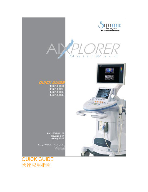
QUICK GUIDE 快速应用指南WELCOME!欢迎!感谢并祝贺您选择Aixplorer®新声威特种鉴别诊断超声系统Aixplorer®新声威特种鉴别诊断超声系统包含以下文本文件:• 快速应用指南• 用户指南本《快速应用指南》包括关于产品使用的基础信息。
并不能替代《用户指南》。
为确保您正常、安全的使用本产品,请仔细阅读《用户指南》。
Aixplorer®新声威特种鉴别诊断超声系统的设计保证将临床操作和患者的安全风险降至合理可行的最低范围。
区域客服代表能够帮助解决您的疑问。
请与区域销售或客服人员联系,获得更多辅助信息。
GETTING STARTED系统开启1. 开/关系统开机按下位于机身后方的I 键按下控制面板左侧扬声器旁的On/Off 键系统启动关机按下控制面板上的On/Off 键主屏幕显示关机菜单选择Yes。
按下机身后方的0 键关闭系统电源。
2. 进入患者信息列表按下控制面板上的Patient 键。
您将看到以下内容:·主屏幕显示患者信息列表·触摸屏显示键盘使用轨迹球和/或键盘箭头移动光标位置。
填写相应数据。
GETTING STARTED系统开启触摸屏上会显示正在输入的文字(键盘上方的白色区域内)。
使用backspace 键删除刚刚输入的文字。
将光标移至需要删除的文字,然后单击Delete LINE,用来删除已经输入的文字。
编辑完成后,按下Patient 键退出患者信息列表。
3. 选择探头和预设置按下控制面板上的Probe 键。
触摸屏上显示探头选项。
单击tab 选择需要的应用系统。
触摸屏上将显示与此应用系统相关的探头。
单击preset 选择适合的探头和预设置条件。
系统将加在选定的预设置条件,并进入实时B-超成像模式。
更多关于系统开启、患者信息或探头选择的详细信息,敬请参考《用户指南》。
B-MODE IMAGINGB-超成像调节以下参数,以获得拥有最佳细节显示和更高分辨率的稳定图像。
易尔里格摄影枪用户手册安装和调节2,生产在瑞典3,恭喜您获得了新的易尔里格!说明书
User ManualSetup andAdjustmentMade in SwedenCongratulations on your new Easyrig! Easyrig is patented and specially designed by a photographer for professional photographers. It can be used with both video and film cameras. EASYRIG is manufactured in Sweden and has been ergonomically tested with optimal results.EASYRIG gives you the advantages of both a handheld camera and tripod mounted camera; i.e. with the speed and mobility of the handheld camera you can still achieve steady pictures. EASYRIG relieves your back and shoulders. The load is redis-tributed to the hips so that you can concentrate on the actual filming. You won’t suffer from a strained back or shoulders as you would from normal handheld shooting and you will be able to work for longer periods of time.After you are finished with your Easyrig, just fold it and put it in the specially designed Petrol bag that your Easyrig is delivered in.Easyrig will be your best tool when you do sport events, docu-mentaries, news, yes, any occasion where handheld camera is required.To get most out of your Easyrig, please read the user manual carefully.Have fun!Johan HellstenUsing the EasyrigIt is as simple to put the Easyrig on as it is with a backpack. Just don’t forget to adjust it so it feels comfortable.The weight of the camera should primarily be on your hips. It is important that the support bar is vertical – if it is lopsided, the load will be unevenly distributed on the hips and the cam-era might hit the bar.The hip belt should be tightened so that the rig doesn’t slide down or around the hips. The shoulder strap is mainly for bal-ancing the Easyrig, and prevent it from tilting.If the support arm is too high or too low, first try adjusting the support bar in relation to the hip belt/vest, or change po-sition of your hips. It is also possile to adjust the tube inside the support bar, but that might require adjusting the tight-ness of the suspension line. Note that there must not be more than 10 cm (4 in) between the lower end of the tube and the adjustment ring.When attaching the hook onto the camera, you might find it easier to put the camera on a table or a bench first. Try and find the right balance before you secure the hook.Don’t forget to fasten the safety line.Hip shotsEasyrig gives you the freedom to shoot from various levels. You simply move the camera down from your shoulder as you would in an ordinary handheld situation – only now you don’t feel more than a fraction of the camera’s weight.When shooting at hip level, lean backwards when pushing the camera forward, thus minimising the load on your back.The length of the suspension line makes it possible to move the camera as far as your arms reach.Fig. 1Undo the buckle and unfold the support arm.Fig. 2Let the tube slide into the back support bar and pull over the bellows.Fig. 2Put on your Easyrig.Adjust the hip belt until you find the rig comfortable.Pull the belt tightly.Fig. 4Attach your camera to the Easyrig. Use your middlefinger to open the hook.Secure the hook by turningthe knob clockwise.Fasten the safety line.Fig. 5Leave a gap of approx. 2 cm (1 inch) between the camera and thesupport arm.Fig. 6If adjustment is needed, loosen the knobs and move the hipbelt and/or the vest to find the right position.Fig. 7By adjusting the side supports you will move the weight onyour hips.Fig. 8Adjust the chest strap if necessary, but don’t pull it too tight.Your Easyrig is now readyto be used.Safety precautionsAlways hold the camera when working with the Easyrig. There is a safety strap which you attach to the camera and hook onto the vest.Never undo the hip belt buckle when the camera is attached to the Easyrig! The weight of the camera will pull the top of the Easyrig down, and you might loose control of the camera. If you fall into water when wearing the Easyrig, it’s important to get the equipment off quickly. Just release the hip belt and shoulder strap buckles and slide the shoulder strap over your arm.Be especially careful when filming in rough terrain. Make sure you wear comfortable shoes and clothing.If you work with the Easyrig under special conditions, i.e. ina car, boat, plane or helicopter, make sure to use a safety beltor harness.Some practical adviceTry to keep the camera as close to your body as possible, to avoid unnecessary strain on your back.When filming upwards, you might find it easier if you have the camera tucked under your arm.When filming at hip or knee level, you can remove the eye piece in order to see better. You could also attach an LCD screen, to get better control of the shot.When shooting at hip level during longer periods of time, rest the camera on the hip belt to increase stability.Avoid getting your clothing creased under the hip belt since it may cause discomfort.Use the Easyrig for transporting your camera to and from the filming site.When folding your Easyrig, always make sure to put the upper part of the support arm inside the hip belt and fasten the buckle at the back of the hip belt. This will prevent the suspension line from wearing.When filming with a cable, fasten it to the Easyrig in order to maintain stability.If you don’t use your Easyrig for more than a couple of months, make sure to store it standing up. Otherwise the shock absorber gasket might dry out.Australia Lemac Sydney:1416 Punch Street Artarmon NSW 2064Phone: +61 2 9438 4488Fax: +61 2 9438 3399email:***************.au web: .au Melbourne:2 Griffiths Street Richmond VIC 3121Phone: +61 3 9429 8588 Fax: +61 3 9428 3336 Brisbane:5 Exhibition Street Bowen Hills QLD 4006Phone: +61 7 3252 9777 Fax: +61 7 3252 9877AustriaAvisys Electronics GmbH Felbigergasse 38, 1140 Wien Phone: +43 1 41 960 10 Fax.: +43 1 41 960 07email:****************.at web: www.avisys.co.atBangladesh Film Trust81 North South Road, 1st. Floor Bijoynagar Dhaka 1000Tel: +880 2 831 6514, 935 1939Fax: +880 2 831 9388Email:******************BelgiumES Video Facilities Technologielaan 33001 HeverleePhone: +32 16 40 40 20Fax: +32 16 40 51 60email:***************web: www.esvideo.be CanadaPrecision Camera Inc. 181 Carlaw AvenueToronto, Ontario, M4M 2SI Phone: +1 416 461 3411 Fax: +1 416 461 4869 web: www.pci Support Communication Inc. 4949 E. MetropolitainMontreal Quebec, H1R 1Z6Phone/fax: +91 514 498 3335Pierre Pelletieremail: SupportCommunication @videotron.caChinaVideotech Consultants Company13B, Fuk Shing Mansion 89 Ma Tau Wai RoadHung Hom, Kln, Hong Kong Phone: +852 2764 9763Fax: +852 2362 5996DenmarkZimmermann Film & Videoteknik H.C. Ørstedsvej 11 B 1879 Frederiksberg C Phone: +45 33 25 85 25 Fax: +45 33 25 85 23email:****************** web: www.zimmermann.dkDubaiUnited Broadcast & Media Showroom #1,Rashid Al Majid Building,Airport Road, Dubai, U.A.E.Phone: +971 4 2827171Fax: +971 4 2827373email:**************web: Egypt Egypt Plus12 Soliman Abaza street Mohandseen, Giza 12311Phone: +20 2 761 3484, 337 3914, 338 0529 Fax: +20 2 337 3914email:*******************FinlandQualitron Oy AbVitikka 4, 02630 EspooPhone: +358 (0)9 2510 1622Fax: +358 (0)9 2510 1690Mobile: +358 (0)50 4653 561email:************************web: www.qualitron.fi Pro Av Saarikko OyOtakuja 2, 02150 Espoo Phone: +358 9 5259 2113Fax: +358 9 5259 2123email:**************web: www.proav.fi France Emit2, Bd de la Libération Urbaparc 1 Bat A393284 Saint DenisPhone :+33 1 48 13 90 10Fax :+33 1 48 13 90 13email:***************Germany FilmtechnikA. Chrosziel GmbH Klausnerring 6 85551 HeimstettenPhone: +49 89 901 09 10 Fax: +49 89 447 08 61 email:***************** web: Great BritainProduction Gear lennium Studios Elstree Way, Borehamwood Herts WD6 1SFPhone: +44 (0)20 8236 1212Fax: +44 (0)20 8236 1414**********************.uk web: Greece M C Manios Arahneou 14 115 22 AthensPhone: +30 210 645 29 95 Fax: +30 210 645 29 97 email:****************web: www.mcmanios.gr HollandVocas Sales & Services Larensweg 1211221 CL HilversumPhone +31 356233 707Fax: +31 356233 997email:********************web: www.vocas.nlFofic b.v.Kruyderlaan 353431 BM Nieuwegein Phone: +31 30 6044422 Fax: +31 30 6047944email:*********************** web: www.fofic.nlIsraelBand Pro Film Video Inc.3 Hasolelim street TelAviv 678970Phone: +972 3 562 1631Fax: +972 3 562 1632email:*********************.il web: ItalyCartoni S.p.A.Via Giuseppe Mirri 13 00159 RomePhone: +39 06 438 2002 Fax: +39 06 435 88293 email:*************** web: JapanSuzuki Enterprises Inc. Daiichi Nishiya bld 2f173 Hatagaya, ShibuyaKu Tokyo 1510072Phone: +81 3 5350 8235 Fax: +81 3 5350 8237 email:***************web: KoreaHuman Network Broadcast RM501 SungWooNetVill919 Mok dong YangcheonGu Seoul, Korea 158051Phone: +82 2 2168 2040Fax: +82 2 2062 2014email:***********.kr web: www.ihnb.co.krDigital Sunwoo Co. ltd 10F, KCE B/D, #1660,Hangangro 3Ka, YongsanKu, Seoul Phone: +82 2 705 1245 Fax: +82 2 705 1244***********************.kr web: www.digitalsunwoo.co.kr Norway Bright ASBrenneriveien 11, 0182 Oslo Phone: +47 22 98 22 22Fax: +47 22 98 22 23email:****************** web: www.brighttech.no Palestina Star 2000P.O. Box 2130, Ramallah Phone: +970 52 88 65 18Fax: +970 52 98 40 37email: star2000@p PolandStudiotech Poland Sp. z.o.o.ul.Taneczna 18 A Pl 02829 Warszawa Phone: +48 22 644 1025Fax: +48 22 648 0171************************.pl web: .pl Russian Federation SintexKasatkina st. 11, build 3, Moscow Phone: +7 495 258 5979Fax: +7 495 258 5979email:**************web: www.sintex.ruCineLine65 bld.5 Leningradskoe shosse 124445, MoscowPhone/fax: +7 095 4584381 email:***************** Slovenia MOPS d.o.o.Papirnica 26, 4220 Skofja Loka Phone/Fax: +386 4 512 18 39Mobile: +386 (0)41 70 63 10email:*************SpainCeproma, S.A.Arturo Soria, 106, Chalet 3 28027 MadridPhone: +34 91 408 60 12 Fax: +34 91 408 28 54email:*******************TaiwanView Point Image Assemblings 6f No. 153 ShueiYuan Rd. TaipeiPhone: +886 2 2303 7899 Fax: +886 2 2301 2028email:*******************.net Turkey SigmaGuniz Sokak 23 / 8Kavaklidere 06700, Ankara Phone: +90 312 4662169Fax : +90 312 4662175email:*********************web: USA 16x9inc.P.O. Box 10142Burbank, CA 91505Phone: +1 818 972 2839Fax: +1 818 972 2832TollFree:186****1699email: web: Abel Cine Tech Inc.609 Greenwich St. 5th Floor New York, NY 10014Phone: +1 888 223 1599Phone: +1 212 462 0100Fax: +1 212 462 0199email:*****************web: If there is no agent in your country, please contact our head office directly:EASYRIG AB Anumark 231S905 95 UmeåSwedenPhone/fax: +46 90 77 60 01email:***************web: www.easyrig.seUp to date agent information found on websiteE a s y r i g a g e n t sEasyrig Warranty Information card Please mail within 30 days of purchase.Name_____________________________ Title___________________Company______________________ Type of business_______________Address__________________________________________________City__________________________ Postal code__________________Country_______________________Phone:________________________ Fax:________________________email:________________________Easyrig serial No:________________Purchase location/company:_____________________ Date: __________Please send to:Easyrig AB Anumark 231 or fax to: +46 90 77 60 01 S905 95 Umeå Sweden Thank you!Easyrig limited WarrantyManufacturer’s products are warranted to be free from defects caused by faulty materials or workmanship for a period of two years from the date of purchase. The liability of the Manufacturer under this warranty is limited to repairing, replacing, or at its option issuing credit for any of its products which are returned by purchaser dur-ing such period provided, however, that:A. Warranty card is properly filled out and returned to Manufacturer within 30 days of purchase.B. Defective merchandise is returned to Manufacturer accompanied by a report of findings indicating the basis of/for rejection and with transportation charges paid by the purchaser.C. That such defects exist and have not been caused by abuse, mis -use, neglect, improper installation or assembly, repair, alteration or accident.In no event shall Manufacturer be liable for collateral or con -sequential damages of any nature. This warranty is in lieu of all other warranties expressed or implied.L a y o u t /p r i n t i n g : O r i g i n a l , U m e å 2007 (1702)。
VICTOR Nivo Multimode Plate Reader 版本说明书
VICTOR Nivo Multimode Plate ReaderMultimode DetectionDescriptionThe VICTOR ® Nivo ™ is a high-performance filter-based multimode plate reader system that can be equipped with all major detection technologies – absorbance, luminescence, fluorescence intensity, time-resolved fluorescence, fluorescence polarization, and Alpha. It is a compact, light-weight instrument designed for life science research laboratories performing routine low-throughput assays, or assay development work, and with diverse application requirements. The system’s software has a modern, workflow-oriented user interface that is easy to learn and includes pre-defined application protocols to get users productive quickly . In addition, MyAssays Desktop Standard software is provided for data analysis.Detection TechnologiesThe system incorporates a dynamic wheel system with space for storage of up to 32 filters, providing ready access to filters for a large number of dyes. Filters are exchanged between the inner and outer filter wheels, so any individual filter can serve either excitation or emission lightpaths. As a result, there’s no need to install new filters when switching between assays, and filters can be locked within the system so they can’t be mislaid in the lab – ideal for multi-user environments. When fully-loaded, the filter system provides the flexibility to detect many dyes with better sensitivityand greater cost-effectiveness compared to a monochromator. For absorbance measurements, there is a choice of either a filter- or a spectrometer-based system. Full spectrum absorbance measurements are ultra-fast – 230 to 1000 nm at selectable resolutions (2.0 nm, 5.0 nm, 10 nm) in less than one second per well. The spectrometer system also allows for the detection of a wide range of dyes or measurement of samples with unknown absorbance spectra. The system also features high-performance Alpha laser technology, validated for use with our proprietary AlphaScreen ® and AlphaLISA ® technologies.Key Features• Available in four configurations - standard models include absorbance, luminescence, and fluorescence; option to add time-resolved fluorescence, fluorescence polarization, and/or Alpha • T op and bottom reading of all standard technologies (with the exception of Alpha) for plate formats up to 1536-wells • Compact, lightweight instrument frees-up bench space and is easy to move • Internal dynamic filter wheel system with space for up to 32 filters • For absorbance, choice of filter-based detection for best sensitivity or spectrometer for wavelength flexibility • Time resolved fluorescence certified for use with proprietary LANCE ® and HTRF ® technologies • Enhanced Security software for regulated environments provides technological controls and features that support 21 CFR Part 11 compliance • Laser based Alpha detection capabilities for fast and sensitive Alpha measurements • Browser-based software enables control from a variety of devices – PC, laptop, or tablet • Controllable via network or Wi-Fi to facilitate remote working and data access • Optional dispenser for applications such as fast kinetics, flash luminescence, or dual addition assays • Integrated temperature control and optional gas control unit to keep cells healthy during long term kinetic assaysFor research purposes only. Not for use in diagnostic procedures.For a complete listing of our global offices, visit /ContactUsCopyright ©2020, PerkinElmer, Inc. All rights reserved. PerkinElmer ® is a registered trademark of PerkinElmer, Inc. All other trademarks are the property of their respective owners.58608 PKIPerkinElmer, Inc. 940 Winter StreetWaltham, MA 02451 USA P: (800) 762-4000 or (+1) 203-925-4602*ATP detected by VICTOR Nivo with dispenser。
AXIS Q3538-LVE 语音智能防盗相机说明书
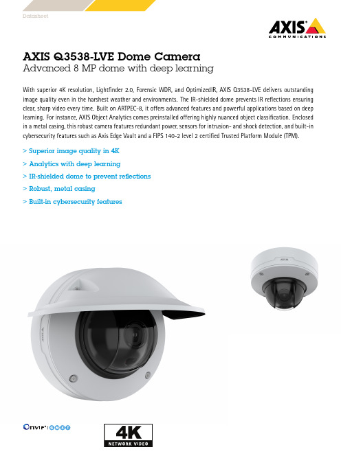
AXIS Q3538-LVE Dome CameraAdvanced8MP dome with deep learningWith superior4K resolution,Lightfinder2.0,Forensic WDR,and OptimizedIR,AXIS Q3538-LVE delivers outstanding image quality even in the harshest weather and environments.The IR-shielded dome prevents IR reflections ensuring clear,sharp video every time.Built on ARTPEC-8,it offers advanced features and powerful applications based on deep learning.For instance,AXIS Object Analytics comes preinstalled offering highly nuanced object classification.Enclosed in a metal casing,this robust camera features redundant power,sensors for intrusion-and shock detection,and built-in cybersecurity features such as Axis Edge Vault and a FIPS140-2level2certified Trusted Platform Module(TPM).>Superior image quality in4K>Analytics with deep learning>IR-shielded dome to prevent reflections>Robust,metal casing>Built-in cybersecurity featuresDatasheetAXIS Q3538-LVE Dome Camera CameraImage sensor1/1.2”progressive scan RGB CMOSLens Varifocal,6.2–12.9mm,F1.6–2.9Horizontal field of view:103°–49°Vertical field of view:56°–28°Varifocal,Remote focus and zoom,P-Iris control,IR correctedDay and night Automatically removable infrared-cut filterMinimum illumination Color:0.07lux at50IRE,F1.6 B/W:0lux at50IRE,F1.6Shutter speed1/66500s to2sCamera angleadjustmentPan±180°,tilt-43to+80°,rotation±175°System on chip(SoC)Model ARTPEC-8Memory2048MB RAM,8194MB Flash ComputecapabilitiesDeep learning processing unit(DLPU) VideoVideo compression H.264(MPEG-4Part10/AVC)Baseline,Main and High Profiles H.265(MPEG-H Part2/HEVC)Main ProfileMotion JPEGResolution Up to3840x2160Frame rate With WDR:25/30fps with power line frequency50/60HzWithout WDR:50/60fps with power line frequency50/60Hz Video streaming Multiple,individually configurable streams in H.264,H.265andMotion JPEGAxis Zipstream technology in H.264and H.265Controllable frame rate and bandwidthVBR/ABR/MBR H.264/H.265Video streaming indicatorMulti-viewstreamingUp to8individually cropped out view areasImage settings Saturation,contrast,brightness,sharpness,Forensic WDR:Up to 120dB depending on scene,white balance,day/night threshold,tone mapping,exposure mode,exposure zones,defogging,barrel distortion correction,electronic image stabilization,compression,rotation:0°,90°,180°,270°including CorridorFormat,mirroring,text and image overlay,dynamic text andimage overlay,privacy masks,polygon privacy maskPan/Tilt/Zoom Digital PTZ,optical zoom,preset positionsLimited guard tour,control queue,on-screen directional indicatorTour recording(max10,max duration16minutes each),guardtour(max100)2x optical zoomAudioAudio streaming Two-way,full duplexAudio encoding24bit LPCM,AAC-LC8/16/48kHz,G.711PCM8kHz,G.726ADPCM8kHz,Opus8/16/48kHzConfigurable bit rateAudio input/output External microphone input or line input(balanced or unbalanced), line output,digital audio input,automatic gain control Microphone power:Microphone power5V on tip,ring power12V on ring, phantom power12V on tip/ringNetworkSecurity Password protection,IP address filtering,HTTPS a encryption,IEEE802.1x(EAP-TLS)a network access control,digestauthentication,user access log,centralized certificatemanagement,brute force delay protection,signed firmware,secure boot,signed video,Axis Edge Vault,Axis device ID,securekeystore(CC EAL4certified),TPM(FIPS140-2certified)Network protocols IPv4,IPv6USGv6,ICMPv4/ICMPv6,HTTP,HTTPS a,HTTP/2,TLS a,QoS Layer3DiffServ,FTP,SFTP,CIFS/SMB,SMTP,mDNS(Bonjour),UPnP®,SNMP v1/v2c/v3(MIB-II),DNS/DNSv6,DDNS,NTP,NTS,RTSP,RTCP,RTP,SRTP,TCP,UDP,IGMPv1/v2/v3,DHCPv4/v6,ARP,SSH,SIP,LLDP,CDP,MQTT v3.1.1,Syslog,Link-Local address(ZeroConf)System integrationApplicationProgrammingInterfaceOpen API for software integration,including VAPIX®andAXIS Camera Application Platform;specifications at One-click cloud connection(O3C)ONVIF®Profile G,ONVIF®Profile M,ONVIF®Profile S,andONVIF®Profile T specification at OnscreencontrolsElectronic image stabilizationDay/night shiftDefoggingWide dynamic rangeVideo streaming indicatorIR illuminationHeaterEvent conditions Analytics,external input,supervised external input,edge storageevents,virtual inputs through APIAudio:audio detection,audio clip playingCall:state,state changeDevice status:above operating temperature,above or belowoperating temperature,below operating temperature,IP addressremoved,network lost,new IP address,shock detected,casingopen,storage failure,system ready,within operating temperatureDigital audio:digital signal contains Axis metadata,digital signalhas invalid sample rate,digital signal missing,digital signal okayEdge storage:recording ongoing,storage disruption,storagehealth issues detectedI/O:digital input,manual trigger,virtual inputMQTT subscribeMQTT:statelessScheduled and recurring:scheduleVideo:tampering,average bitrate degradation,day-night mode,live stream openEvent actions I/O:toggle I/O once,toggle I/O while the rule is activeRecord video:SD card and network shareUpload of images or video clips:FTP,SFTP,HTTP,HTTPS,networkshare and emailPre-and post-alarm video or image buffering for recording oruploadNotification:email,HTTP,HTTPS,TCP and SNMP trapCalls:end SIP call,make SIP call,answer callMQTT publishOverlay text,external output activation,play audio clip,zoompreset,day/night mode,make call,flash status LED,use lights,set defog mode,send MQTT publish message,set WDR modeBuilt-ininstallation aidsLeveling assistant,straighten image,image grid,pixel counterAnalyticsAXIS ObjectAnalyticsObject classes:humans,vehicles(types:cars,buses,trucks,bikes)Trigger conditions:line crossing,object in area,time in area BETAUp to10scenariosMetadata visualized with trajectories and color-coded boundingboxesPolygon include/exclude areasPerspective configurationONVIF Motion Alarm eventMetadata Object data:Classes:humans,faces,vehicles(types:cars,buses,trucks,bikes),license platesConfidence,positionEvent data:Producer reference,scenarios,trigger conditionsApplications IncludedAXIS Object AnalyticsAXIS Video Motion Detection,active tampering alarm,audiodetectionSupportedSupport for AXIS Camera Application Platform enablinginstallation of third-party applications,see /acapGeneralCasing IP66-,IP6K9K-,NEMA4X-and IK10+-ratedPolycarbonate hard coated domeAluminum and plastic casing,polycarbonate(PC)dome,sunshield(PC/ASA)Color:white NCS S1002-BThis product can be repaintedFor repainting instructions of casing and impact on warranty,contact your Axis partner.Mounting Mounting bracket with junction box holes(double-gang,single-gang,4”square,and4”octagon)¾”(M25)conduit side entrySustainability PVC freePower Power over Ethernet(PoE)IEEE802.3at Type2Class4Typical9W,max23W10–28V DC,typical9W,max24WConnectors Shielded RJ4510BASE-T/100BASE-TX/1000BASE-T PoEDC input,3.5mm mic/line in,3.5mm line outTerminal block for two configurable supervised inputs/digitaloutputs(12V DC output,max load50mA)IR illumination OptimizedIR with power-efficient,long-life850nm IR LEDsRange of reach40m(130ft)or more depending on the scene Storage Support for microSD/microSDHC/microSDXC cardSupport for SD card encryption(AES-XTS-Plain64256bit)Recording to network-attached storage(NAS)For SD card and NAS recommendations see Operating conditions -50°C to55°C(-58°F to131°F)Maximum temperature according to NEMA TS2(2.2.7):74°C (165°F)Start-up temperature:-40°C(-40°F)Humidity10–100%RH(condensing)Storage conditions -40°C to65°C(-40°F to149°F) Humidity5-95%RH(non-condensing)Approvals EMCCISPR35,EN50121-4,EN55032Class A,EN55035,EN61000-3-2,EN61000-3-3,EN61000-6-1,EN61000-6-2,FCC Part15Subpart B Class A,ICES-3(A)/NMB-3(A),IEC62236-4,KS C9832Class A,KS C9835,RCM AS/NZS CISPR32Class A,VCCI Class ASafetyCAN/CSA-C22.2No.60950-22,CAN/CSA C22.2No.62368-1,IEC/EN/UL62368-1,IEC/EN/UL60950-22,IEC62471,IS13252EnvironmentIEC60068-2-2,IEC60068-2-6,IEC60068-2-14,IEC60068-2-27,IEC60068-2-78,IEC/EN60529IP66,ISO20653IP6K9K,IEC/EN62262IK10+(50J),NEMA250Type4X,NEMA TS2(2.2.7-2.2.9)NetworkNIST SP500-267Dimensions Height:124mm(4.9in),184mm(7.3in)including weathershield ø183mm(7.2in)Weight 2.1kg(4.6lb)including weathershieldIncludedaccessoriesInstallation guide,Windows®decoder1-user license,drill holetemplate,terminal block connectors for DC and I/O,RESISTORX®L-key,connector guard,cable gasket,conduit adapter,mountingbracket,weathershieldOptionalaccessoriesAXIS T8415Wireless Installation ToolAXIS Surveillance CardsAXIS TQ3807-E Dome Smoked,AXIS T94M01D Pendant KitFor more accessories,see VideomanagementsoftwareAXIS Companion,AXIS Camera Station,video managementsoftware from Axis Application Development Partners availableat /vmsLanguages English,German,French,Spanish,Italian,Russian,SimplifiedChinese,Japanese,Korean,Portuguese,Polish,Traditional Chinese Warranty5-year warranty,see /warrantya.This product includes software developed by the OpenSSL Project for use in the OpenSSL Toolkit.(),and cryptographic software written by Eric Young (*****************).Environmental responsibility:/environmental-responsibility©2021-2022Axis Communications AB.AXIS COMMUNICATIONS,AXIS,ARTPEC and VAPIX are registered trademarks ofAxis AB in various jurisdictions.All other trademarks are the property of their respective owners.We reserve the right tointroduce modifications without notice.T10168579/EN/M11.2/2211。
VIO学习之配置VIO
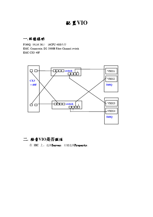
配置VIO一.环境说明P560Q(9116-561)16CPU 48G内存EMC. Connectrix. DS-5000B Fibre Channel switchEMC CX3-40F二. 检查VIO是否激活在 HMC 上,选择Server,右键选择Property。
如上图两项为TRUE时,表示已激活。
三. 划分VIO SERVER分区1.在 HMC 上,打开Server和Partition文件夹,然后打开ServerManagement文件夹。
2.右键单击想要在其上创建分区的所管理系统,选择Create,然后选择Logical Partition。
3.为您的 VIO Server 提供名称,在Partition Environment框中选择Virtual I/O Server单选按钮,单击Next4.暂时不使用工作负载管理,直接单击Next。
5.为您的分区输入概要名称,并确保未选中Use all the resources in thesystem复选框。
单击Next。
6.输入您确定对系统适当的内存量。
VIO Server 至少需要512MB 的RAM。
LPAR 分配整个处理器。
这里我们选择Shared。
8.输入最低、所需和最大处理单元(CPU) 数量。
9.此时将向您显示系统上已安装的 I/O 设备。
对于VIO Server,必须至少分配一个存储控制器和一个以太网卡(因为共有两个VIO Server,所以可以将全部I/O设备的一半分配给每个VIO Server),单击Add as required。
光驱只有一个,所以应该设为Add as desired(下图中的Slot T15),以便以后在分区间迁移。
10.I/O Pool 面板用于 i5/OS,所以对于 VIO Server、AIX 和 Linux 分区,可忽略该面板。
单击Next。
11.选择Yes, I want to specify virtual I/O adapters,然后单击Next。
南京卫人科技有限公司 铱星终端 N5-I 技术说明书
编号密级版本铱星终端N5-I技术说明书编写校对审核会签批准南京卫人科技有限公司铱星终端N5-I技术说明书目次1概述 (1)2技术特征 (2)2.1产品功能 (2)2.2产品性能 (2)2.2.1GNSS单元指标 (2)2.2.2铱星单元指标 (3)2.2.3电源特性 (3)2.2.4环境适应性 (3)2.2.4其他 (4)3、组网拓扑 (4)4接口按键定义 (4)4.1对外接口 (4)4.2按键定义 (4)3.3指示灯定义 (5)4结构尺寸 (5)5终端连接 (6)6终端使用 (6)6.1使用步骤 (6)6.2注意事项 (7)7固件升级 (7)8标准配件 (7)9变更记录 (8)1概述铱星终端N5-I(以下简称终端)是我司推出的一款同时支持铱星SBD报文功能、全球定位功能、语音播报等功能以及蓝牙连接的终端产品。
终端与智能手机通过蓝牙连接,用户可以通过手机端专用app 实现位置服务、铱星短报文通信、GNSS定位、自动位置上报、SOS 报警等功能。
2技术特征2.1产品功能(1)铱星SBD短报文功能;(2)GNSS定位功能;(3)语音播报、提示功能;(4)支持终端状态查询功能;(5)支持蓝牙4.0连接;(6)支持一键开关机;(7)支持SOS按键报警功能;(8)支持落水自动报警功能;(9)内置锂电池供电;(10)支持磁吸充电;(11)支持设备内温湿度、气压参数检测功能。
2.2产品性能2.2.1GNSS单元指标●支持频点:BDS_B1/GPS_L1;●定位精度:≤10m;●冷启动时间:≤50s;●热启动时间:≤5s;●RNSS刷新率:1Hz(默认);2.2.2铱星单元指标●IRIDIUM频率:1616MHz to1626.5MHz●卫星覆盖范围:全球覆盖、卫星可视范围内无盲区;●卫星传输方式:全双向数据传输;●数据业务:铱星短数据SBD业务,●数据能力:单次发送最大340bytes,接收最大270bytes;●组网方式:终端-IP服务器-终端;●通信可靠性:高可靠性、没有数据丢失和误码;2.2.3电源特性●待机时间:模式待定;●报警工作时间:≥24小时(SOS模式);●电池充电:1.5A@5V(充电温度0℃-45℃)●电池放电:-20℃~+55℃●电池容量:2500mAh;2.2.4环境适应性●工作温度:-10℃~+60℃;●贮存温度:短期(1个月内):-20℃~+60℃中期(3个月内):-20℃~+45℃长期(1年):-5℃~+30℃●防护等级:IP67,抗1.2米落摔;2.2.4其他●重量:≤160±5g;●尺寸:98*59*23mm。
PowerVM常用命令手册
PowerVM常用命令手册目录目录 (1)1. 基本操作 (3)2. 创建VIOS分区 (3)3. VIOS配置 (7)3.1 创建共享以太网卡SEA(Shared Ethernet Adapter) (7)3.2 创建VSCSI虚拟磁盘 (7)3.3 NPIV配置 (12)3.4 参数调整 (16)3.5 VIO测试 (18)3.6 设置VIO Server分区自动启动 (19)4. VIOS巡检工作 (21)5. 虚拟资源的调整 (22)6. VIOS、VIOC配置实例 (25)7. WPAR技术 (32)7.1 创建Application WPAR (33)7.2 创建System WPAR (34)7.3 如何确定当前是在Global Environment中还是在WPAR中 (36)7.4如何关闭WPAR (36)7.5 如何重启WPAR (37)7.6修改WPAR的名字 (39)7.7 WPAR的状态 (39)7.8 删除WPAR (40)7.9 WPAR中的文件系统管理 (41)7.10 同步WPAR配置 (45)7.11备份、恢复、克隆WPAR (45)7.12 WPAR用户和组管理 (46)7.13 恢复WPAR中的用户口令 (46)7.14修改MPIO磁盘的hcheck_interval属性 (47)8. 存在多个VLAN ID的TCP/IP网络 (47)9. Active Memory Expansion(AME)技术 (50)10. 备份和恢复VIO Server (53)10.1 备份VIO Server (53)10.2 恢复VIO Server (55)11. 故障处理 (56)11.1 收集虚拟资源配置信息 (56)11.2更换VIO Server的SEA物理网卡 (56)12. topas性能监控 (58)1. 基本操作默认用户:padmin默认无密码默认用户环境为受限的Korn Shell切换到AIX root用户环境命令:oem_setup_env安装VIOS系统installios接受VIOS License文件命令:license -accept升级VIOS版本命令:updateios -commitupdateios -accept -install -dev /dev/cd0ioslevelshutdown -restart备份VIOS的配置:viosbr -backup -file /home/padmin/<backupfile_name>恢复VIOS的配置:viosbr -restore -file <backupfile_name>.tar.gz备份VIOS系统backupiosroot用户环境下输入VIOS配置命令:/usr/ios/cli/ioscli lsmap -all查看分区的CPU、内存配置lparstat -i2. 创建VIOS分区一个shared、uncapped Processor分区作为VIOS分区即可,在同一台服务器上可以部署多个VIOS分区,例如在网络IO和磁盘IO都很繁忙的应用环境,可以部署四个VIOS分区,其中两个VIOS负责处理Virtual Ethernet,另外两个VIOS负责处理Virtual Disk。
Waves eMotion LV1 Live Mixer 用户手册说明书
UsermanualMIDI/Audio control surface with motorized fadersFor the Waves eMotion LV1 Live MixerImportant Safety Instructions1. Read this manual thoroughly before using this unit.2. Keep this manual for future reference.3. Take notice of and comply with all warnings included in the user's manual or indicated on theappliance.4. Follow all instructions included in this manual.5. Do not expose this unit to rain or moisture. Avoid having water or other liquids spilled on thisunit.6. When cleaning the cabinet or other parts of this appliance, use only a dry or slightly damp softcloth.7. Do not block any ventilation openings or interfere with the proper ventilation of this unit. Installin accordance with the manufacturer's instructions.8. Do not use or store near any heat sources such as radiators, heat registers, stoves, or other heat-producing appliances.9. Do not interfere with the safety purpose of the polarized or grounding-type plug. A polarized plughas two blades with one wider than the other. A grounding-type plug has two blades and a third grounding prong. These are designated for your safety. If the provided plug does not fit into your outlet, consult an electrician.10. Protect the power cord from being walked on or otherwise damaged by items placed on oragainst them. Particular attention should be given to the plugs, receptacles, and the point where the cord exits the appliance.11. To avoid the risk of electrical shock, do not touch any exposed wiring while the unit is inoperation.12. Only use attachments/accessories specified by the manufacturer.13. Unplug this unit and all connected electrical equipment during lightning storms or when leftunused a long period of time.14. Refer all servicing to qualified service personnel. Servicing is required when the appliance hasbeen damaged in any way or fails to operate normally.WARNING: To reduce the risk of fire or electric shock, do not expose this unit to rain or moistureContentsIntroduction (4)What's in the package? (4)Features (5)Front Panel Layout (6)Side Panel Layout (8)Getting Started (9)Connecting Your Platform M WAVES Controller (9)Specifications (12)4IntroductionWhat's in the package?Thank you for purchasing the ICON Platform M WAVES M IDI /Audio control surface. We sincerely trust this product will provide years of satisfactory service, but if anything is not to your complete satisfaction, we will endeavor to make things right.In these pages, you'll find a detailed description of the features of the Platform M WAVES, as well as a guided tour through its front and rear panels, step-by-step instructions for its setup and use, and full specifications.You'll also find a warranty card enclosed —please don't forget to fill it out and mail it so that you can receive online technical support at: . And so we can send you updated information about this and other ICON products in the future. As with most electronic devices, we strongly recommend you retain the original packaging. In the unlikely event the product must be returned for servicing, the original packaging (or reasonable equivalent) is required.With proper care and adequate air circulation, your Platform M WAVES will operate without any trouble for many years. We recommend that you record your serial number in the space provided below for future reference.Please write your serial number here for future reference:Purchased at:Date of purchase:●Platform M WAVES USB-MIDI Controller x 1pc●CD x 1App software – iMap (Mac & Windows)User manual & QSGDAW software●Quick Start Guide x 1●USB2.0 Cable x 1●AC adaptor x 1pc5Features●Extremely compact, durable, and versatile●Customize the perfect setup with a variety of platform extension modules ●8 touch-sensitive motorized channel faders with 10-bit resolution● 1 touch-sensitive motorized fader for the master channel, with 10-bit resolution ●8 dual-function encoder knobs (rotate and enter)●Jog wheel for assigned control and menu access.●Illuminated buttons for each channel, including Sel, Mute, Solo● 6 illuminated mode and function buttons●Illuminated menu buttons with two directional navigation keys (Left/Right and Up/Down), used in combination with the jog wheel●4 illuminated buttons for shifting channel bank s and control pages●Class-compliant with Windows XP , Vista (32-bit), Windows 7/8/10 (32-bit & 64-bit) Mac OS X (IntelMac)●USB 2.0 high-speed connectivity●Superior build quality and robust metal casing with Kensington lock port ●12V/2.5A power adapter included1.Channel fadersThe eight 100mm motorized faders are generally used for controlling channelvolume. They are all touch sensitive to allow override automation the momentyou touch a fader. Also, they are motorized; they will automatically move toreflect the current level of the selected channels in your LV1.2.Master faderThis 100mm motorized fader operates the same as the other 8 faders. It can beassigned to any mixer channel.3.KnobsThe eight rotary encoder knobs are generally used for controlling the track panposition, aux send levels, and EQ and dynamics plugin parameters.4.Control buttons4a) Channel control buttons sectionREC buttons - currently not implemented.SOLO buttons - Turn on and off the solo/cue state of the associatedchannel. The switch lights red when the channel solo or cue state is on and other channels are muted.MUTE buttons - Activate and deactivate the mute state of the associatedchannel. The switch will light red when the channel is muted.SEL buttons - Selects the associated channel for processing control. Achannel does not need to be selected to use its fader or to activate muteor solo.64b) ArrowsControlsLeft Arrow: Toggle to previous rotary controls pageRight Arrow: Toggle to next rotary controls pageLayersLeft Arrow: Toggle to previous fader bank layer page4c) Rotary and other controlsInput Assign rotary controls to channel Input controls pagesSend Assign rotary controls to channel FX/Mon auxiliary sends controls pagesPan Assign rotary controls to channel Pan/Imager controls pagesRack Assign rotary controls to channel Rack and Plugins controls pagesEQ Assign rotary controls to channel EQ controls pagesDYN Assign rotary controls to channel Dynamics controls pagesFlip Flip rotary controls with corresponding fadersAuxiliaries sends on faders mode automatically activates this function.!T empo Tap tempoClear Solo Clear all channels that are in Cue or Solo modesMenu Navigate within the Scenes menu5.Jog wheelThe Jog Wheel can be assigned to any selected control (rotary or click) inthe Mixer or Channel window. A mixer control that’s being controlledexternally is highlighted red.The Jog Wheel can also be used to navigate through the Scenes menu inorder to recall scenes. This mode is activated with the two Menu buttonsabove the wheel. Click the right button; the Jog Wheel moves menuselection up or down. When the left button is clicked, the Jog Wheel movesmenu selection right or left. Click on the wheel to recall the selected scene.To return to normal Jog Wheel operation, deselect the Menu buttons.78Side Panel LayoutB portFunctions as a MIDI port to your notebook (or computer) and compatible software.2.LCD Module (Platform D/Platform D2)Connect your Platform D/Platform D2 here with the provided cable.3.12V/2.5A power adaptorConnect the provided power adaptor here.(Note: Platform M WAVES cannot work without the provided power adaptor connected. The USB bus power is not able to provide sufficient power supplyfor Platform M WAVES.)9Getting StartedConnecting Your Platform M WAVES ControllerConnect the Platform M WAVES to your Mac/PC via the USB portChoose a USB port on your Mac/PC and insert the wide (flat) end of the USB cable. Connect the cable’s other end to the Platform M WAVES. Your Mac/PCshould automatically “detect” the new hardware and notify you that it is ready to use.3210eMotion LV1 SetupSystem Inventory Page11eMotion LV1 SetupMackie Control PanelSpecificationsConnector: To computer USB connectorPower supply: 12V/2.5A DCCurrent consumption: 2.0A or lessWeight: 1.765kg (3.89lb)Dimensions: 395(L) x 196(W) x 58(H)mm15.6”(L) x 7.7”(W) x 2.3”(H) 12/iconproaudio /iconproaudio/iconproaudio。
VIS Infinera 12x1 4x1 VCSEL芯片数据表说明书

No. 120314-Rev 1.0March 2012Product CParameter Typical NotesEmission Wavelength 850 nmavailable from 835 – 860 nm Data RateUp 28 Gbit/s per channel Rise time (20% to 80%) < 15 ps Threshold Current 1.0 mA Peak Output Power7 mWProduct Description Product DescriptionThese compact and very high modulation rate top-emitting GaAs-based vertical cavity surface emitting laser (VCSEL) chips and 1xN (N=1, 2, 4, 12, etc.) arrays are available as engineering samples for use in the development and evaluation of opticalinterconnections, optical backplanes and integrated waveguides, and next-generation optical data communications systems. The VCSELs are contacted on the top-surface individually using ground-source (GS) microprobes, wire bonds, or flip-chip bonds.DatasheetFeatures· available in 4x1 and 12x1configuration · up to 28 Gbit/s per channel · high temperature stability · standard pitch size 250 µm · high device-to-device uniformity Applications· 40/100 Gbit/s Ethernet · Infiniband FDR · OTU4 100 Gbit/s· Proprietary optical interconnects · Active Optical Cables (AOC)VI Systems GmbH Hardenbergstrasse 7 D-10623 Berlin28 Gbit/s VCSELs and VCSEL Arrays (850 nm)Product Code:V25B-850C 1x1 V25B -850C4 4x1 arrayV25B -850C12 12x1 arrayPreliminarySample image only. Actual product may vary.DatasheetV25B-850CPreliminary Electro Optical SpecificationsAbsolute Maximum RatingsAll product specifications and descriptions are subject to change without notice. VI Systems GmbH Hardenbergstrasse 7 D-10623 Berlin No. 120314-Rev 1.0 March 2012No. 120314-Rev 1.0March 2012DatasheetV15-850CPreliminaryVI Systems GmbH Hardenbergstrasse 7 D-10623 BerlinNo. 120314-Rev 1.0March 2012All product specifications and descriptions are subject to change without notice.Pleasecontactoursalesdepartmentforadditionalinformationandtoreceiveaquotation:*********************VI Systems GmbH Hardenbergstrasse 7 D-10623 BerlinThe V25B-850C has been tested to meet specifications outlined in this data sheet at room temperature. However, it has not undergone full qualification testing or characterization and therefore may not meet the performance specifications over all extremes.Limited Qualification NotificationVI Systems GmbH Hardenbergstrasse 7 10623 BerlinTel.: +49 30 3083143 30 Fax: +49 30 3083143 59 *********************DatasheetV25B-850C。
ibm VIOS实现双机的方案
PowerVM Editions:
PowerVM Enterprise Edition PowerVM Standard Edition PowerVM Express Edition
IBM虚拟化 技术发 展历 程
A 40 year tradition culminates with PowerVM
v S C S I v L A N
AIX 5L Linux AIX 5L Linux V5.3 V5.3
A1 B1 B2 A2 B3 A3
A1 A2
A3
A4 A5
B1 B2 B4 B5 B3 VIOS owns physical disk resources LVM based storage on VIO Server Physical Storage can be SCSI or FC Local or remote Micro-partition sees disks as vSCSI (Virtual SCSI) devices Virtual SCSI devices added to partition via HMC LUNs on VIOS accessed as vSCSI disk VIOS must be active for client to boot Virtual SCSI
vSCSI specifics
– Storage Virtualizer: - FC, SCSI, iSCSI, SAS, SATA, USB - SCSI Target - SCSI peripheral device types: - Disk (backed by physical volume, logical volume, or file) - Optical (backed by physical optical, or file) - Tape (backed by physical tape) - Adapter and device level sharing
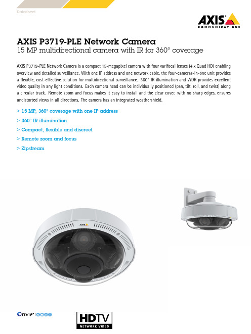
AXIS P3719-PLE 网络摄像头:15 MP 多方向摄像头,四个矫正焦距的 Quad HD
AXIS P3719-PLE Network Camera15MP multidirectional camera with IR for360°coverageAXIS P3719-PLE Network Camera is a compact15-megapixel camera with four varifocal lenses(4x Quad HD)enabling overview and detailed surveillance.With one IP address and one network cable,the four-cameras-in-one unit provides a flexible,cost-effective solution for multidirectional surveillance.360°IR illumination and WDR provides excellent video quality in any light conditions.Each camera head can be individually positioned(pan,tilt,roll,and twist)along a circular track.Remote zoom and focus makes it easy to install and the clear cover,with no sharp edges,ensures undistorted views in all directions.The camera has an integrated weathershield.>15MP,360°coverage with one IP address>360°IR illumination>Compact,flexible and discreet>Remote zoom and focus>ZipstreamDatasheetAXIS P3719-PLE Network Camera CameraImage sensor4x1/2.5”progressive scan RGB CMOSLens Varifocal,3–6mm,F1.8–2.64x1440p capture mode:Horizontal field of view:101°–49°Vertical field of view:54°–29°Diagonal field of view:116°–58°Motorized focus,motorized zoomDay and night Automatically removable infrared-cut filterMinimum illumination Color:0.20lux at50IRE F1.8B/W:0.04lux at50IRE F1.8,0lux with IR illumination onShutter speed1/66500s to1/5s with50/60HzCamera angleadjustmentPan±90°,tilt+25to+95°,rotation–5to+95°,twist±20°System on chip(SoC)Model S5Memory2048MB RAM,512MB FlashVideoVideo compression H.264(MPEG-4Part10/AVC)Main and High Profiles H.265(MPEG-H Part2)Resolution4x2560x1440(4x Quad HD)to4x640x360Frame rate Up to25/30fps(50/60Hz)Video streaming Multiple,individually configurable streams in H.264and H.265Axis Zipstream technology in H.264and H.265Controllable frame rate and bandwidthVBR/ABR/MBR H.264Image settings Saturation,contrast,brightness,sharpness,WDR,white balance, exposure control,rotation:0°,90°,180°,270°including CorridorFormat,dynamic text and image overlay,polygon privacy mask,compressionAudioAudio input/output Two-way audio connectivity via optional AXIS T61Audio and I/O Interfaces with portcast technologyA30W midspan or higher between AXIS T61Audio and I/O Interfaces and AXIS P3719-PLE is required.NetworkIP address One IP address for all channelsNetwork protocols IPv4,IPv6USGv6,ICMPv4/ICMPv6,HTTP,HTTP/2,HTTPS,TLS,QoS Layer3DiffServ,FTP,CIFS/SMB,SMTP,mDNS(Bonjour),UPnP TM, SNMP v1/v2c/v3(MIB-II),DNS/DNSv6,DDNS,NTP,NTS,RTSP, RTP,SRTP/RTSPS,SFTP,TCP,UDP,IGMPv1/v2/v3,RTCP,ICMP, DHCPv4/v6,ARP,SSH,LLDP,CDP,MQTT v3.1.1,Secure syslog (RFC3164/5424,UDP/TCP/TLS),Link-Local address(ZeroConf)System integrationApplication Programming Interface Open API for software integration,including VAPIX®and AXIS Camera Application Platform;specifications at One-click cloud connectionONVIF®Profile G,ONVIF®Profile M,ONVIF®Profile S and ONVIF®Profile T,specification at Event triggers Detectors,hardware,input signal,storage,system,time,analytics,edge storage eventsMQTT subscribeEvent actions Day/night vision mode,overlay text,record video,send images, send notification,send SNMP trap,send video clip,status LEDFile upload:FTP,HTTP,HTTPS,network share,SFTP and emailNotification:email,HTTP,HTTPS,TCP and SNMP trapMQTT publishData streaming Event dataBuilt-ininstallation aidsPixel counter,remote focus,remote zoomAnalyticsApplications IncludedAXIS Motion Guard,AXIS Fence Guard,AXIS Loitering GuardAXIS Video Motion Detection,active tampering alarmSupport for AXIS Camera Application Platform enablinginstallation of third-party applications,see /acap CybersecurityEdge security Software:Signed firmware,brute force delay protection,digest authentication,password protectionNetwork security IEEE802.1X(EAP-TLS),HTTPS/HSTS,TLS v1.2/v1.3,Network Time Security(NTS),X.509Certificate PKI,IP address filtering Documentation AXIS OS Hardening GuideAxis Vulnerability Management PolicyAxis Security Development ModelAXIS OS Software Bill of Material(SBOM)To download documents,go to /support/cybersecu-rity/resourcesTo read more about Axis cybersecurity support,go to/cybersecurityGeneralCasing IP66-,IP67-,NEMA4X-rated,IK09impact-resistant,aluminium and plastic casing with polycarbonate hard-coated dome,sunshield(PC/ASA)Color:white NCS S1002-BFor repainting instructions of casing and impact on warranty,contact your Axis partner.Mounting Mounting bracket with junction box holes(double gang box,single gang box,4”octagon junction box and4”square junctionbox)½”(M20)conduit side entry¾”(M25)conduit adapter includedSustainability PVC freePower Power over Ethernet(PoE)IEEE802.3at Type2Class4IR illumination on:class4,typical16.3W,max25.5WIR illumination off:class3,typical10.7W,max25.5W Connectors Shielded RJ4510BASE-T/100BASE-TX/1000BASE-T PoEAudio and I/O connectivity via AXIS T61Audio and I/O Interfaceswith portcast technology.IR illumination Four individually controllable IR with power-efficient,long-life850nm IR LEDsRange of reach15m(50ft)or more depending on the scene Storage Support for microSD/microSDHC/microSDXC cardDual SD cardsSupport for SD card encryption(AES-XTS-Plain64256bit)Support for recording to network-attached storage(NAS)For SD card and NAS recommendations see Operatingconditions-30°C to50°C(-22°F to122°F)Humidity10–100%RH(condensing)Maximum temperature according to NEMA TS2(2.2.7):74°C(165°F)Storageconditions-40°C to65°C(-40°F to149°F)Approvals EMCEN55032Class A,EN50121-4,IEC62236-4,EN61000-3-2,EN61000-3-3,EN55024,EN61000-6-1,EN61000-6-2,FCC Part15Subpart B Class A,ICES-003Class A,VCCI Class A,RCM AS/NZS CISPR32Class ASafetyIEC/EN/UL62368-1,IEC/EN/UL60950-22,IS13252,IEC62471EnvironmentIEC60068-2-1,IEC60068-2-2,IEC60068-2-6,IEC60068-2-14,IEC60068-2-27,IEC60068-2-78,IEC/EN60529IP66/67,IEC/EN62262IK09,NEMA250Type4X,NEMA TS2(2.2.7-2.2.9)NetworkNIST SP500-267Dimensions Height:91.5mm(3.6in)ø255mm(10.04in)Weight 2.0kg(4.4lb)IncludedaccessoriesRJ45mounting tool,screw bit TR20,Installation guide,Windows®decoder1-user licenseOptionalaccessoriesAXIS T94N01D Pendant KitAXIS T94N01L Recessed MountAxis mounts and cabinetsFor more accessories,see Video management software AXIS Companion,AXIS Camera Station,video managementsoftware from Axis’Application Development Partners availableon /vmsLanguages English,Simplified Chinese,Traditional Chinese,Dutch,Czech,Swedish,Finnish,Turkish,Thai,Vietnamese,French,German,Italian,Japanese,Korean,Polish,Portuguese,Russian,SpanishWarranty5-year warranty,see /warranty©2018-2023Axis Communications AB.AXIS COMMUNICATIONS,AXIS,ARTPEC and VAPIX are registered trademarks ofAxis AB in various jurisdictions.All other trademarks are the property of their respective owners.We reserve the right tointroduce modifications without notice.T10134016/EN/M31.2/2310。
小型机AIX教程十五

实验15项目名称:日常维护及配置(一)1、实验目的了解小型机系统日常维护及配置的基本内容。
掌握系统及用户环境管理的基本方法。
在理解系统日志概念的基础上,掌握错误日志文件的管理方法。
2、实验内容日常维护及配置的基本内容前面我们分别按专题分别介绍了在小型机系统上对用户、进程、内存、文件系统、存储、外围设备以及网络等方面的基本管理。
本实验则是从用户与系统环境的维护及配置角度,讨论系统管理员日常需做各项工作,其中包括系统及用户环境的配置、系统日志的管理与维护、错误和异常的排查和分析、系统安全管理、基本的数据备份和恢复等等。
这些工作本身并不对应于系统中的某个硬件或软件子系统,但却贯穿于系统管理工作的始终,系统管理员往往是通过这些日常工作逐渐积累各种经验,特别是对系统各类问题,如硬件错误、安全异常等方面的经验,最终成为一名优秀的系统管理员。
因此,这些系统管理知识和技能是大家所必须掌握的内容。
本专题分为两部分,本次实验主要介绍系统及用户环境的配置、系统日志的管理与维护等方面的内容。
系统及用户环境管理对于一个系统管理员,在开展工作前,最起码要对当前系统和用户所使用的环境有一个基本的了解。
以下所介绍的命令,主要用在获取基本系统和用户环境的基本信息。
命令:lscfg功能:显示系统的配置信息、诊断信息和重要产品的信息格式:lscfg例子:lscfg命令的使用#lscfgINSTALLED RESOURCE LISTThe following resources are installed on the machine.+/- = Added or deleted from Resource List.* = Diagnostic support not available.Model Architecture: chrpModel Implementation: Multiple Processor, PCI bus+ sys0 System Object+ sysplanar0 System Planar* vio0 Virtual I/O Bus* vsa1 LPAR Virtual Serial Adapter* vty1 Asynchronous Terminal* vsa0 LPAR Virtual Serial Adapter显示单个设备的基本信息#lscfg | grep ProcessorModel Implementation: Multiple Processor, PCI bus+ proc0 Processor+ proc2 Processor问题:请完成如下问题,并将截图结果附于问题之后。
VIO S118 快速入门手册说明书
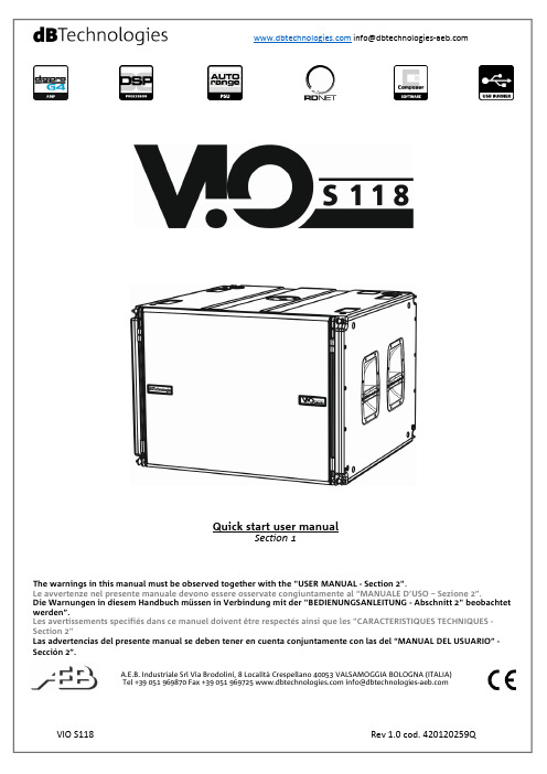
Quick start user manualSection 1The warnings in this manual must be observed together with the "USER MANUAL - Section 2".Le avvertenze nel presente manuale devono essere osservate congiuntamente al “MANUALE D’USO – Sezione 2”.Die Warnungen in diesem Handbuch müssen in Verbindung mit der "BEDIENUNGSANLEITUNG - Abschnitt 2" beobachtet werden”.Les avertissements specifiés dans ce manuel doivent être respectés ainsi que les "CARACTERISTIQUES TECHNIQUES -Section 2"Las advertencias del presente manual se deben tener en cuenta conjuntamente con las del “MANUAL DEL USUARIO” - Sección 2”.A.E.B. Industriale Srl Via Brodolini, 8 Località Crespellano 40053 VALSAMOGGIA BOLOGNA (ITALIA)Thank you for choosing a dBTechnologies Product!VIO S118 is an active horn loaded subwoofer, designed for professional use, easy to fly, equipped with one 18” woofer (voice coil: 4”). The powerful DIGIPRO® G4 amplifier section, capable of handling up to 1600 W (RMS power), is controlled by a DSP, which can perform a detailed customization of the output sound of the subwoofer. In particular, thanks to the complete control interface, it is possible to accurately tune various types of configurations, like cardioid or end-fire. The RDnet connections allow in-depth remote control, thanks also to free available software (dBTechnologies Network, dBTechnologies Composer). WPD (wireless position detection) is a new feature which allows recognizing the placement of the subwoofer in line-array (in the real use). Professional accessories (like FSA-VIOL210 flown adapter, GSA-VIOL210 stack adapter, DRK-210 fly-bar, DO-VIOS118 dolly) ensure easy set-up to create different configurations, completing live installations with VIO-L210 line-arrays.Check the site for the complete user manual!1) UnpackingThe box contains:No. VIO S118No. 1 Mains cable with Neutrik® powerCON TRUE1connectorNo. 1 FuseThis quick start and warranty documentation2) Easy installationThe quick assembly in line-array is guaranteed by:UPPER SIDEfront retractable brackets (A), for anchoring to ahigher subwoofer or DRK-210 fly-bar (flowninstallation)rear retractable brackets(B), for anchoring to ahigher subwoofer, to DRK-210 fly-bar (flowninstallation) or to GSA-VIOL210 (stacked installation)quick-release pins (C) for securing the retractablebracketsLOWER SIDEfront anchorage system(D), for anchoring to alower subwoofer or to VIO-L210 module (flowninstallation)rear anchorage system (E), for anchoring to alower subwoofer or to FSA-VIOL210 (flowninstallation)TOP AND LATERAL SIDESpick points forDRK- 210 fly-bar (F)(stacked mounting)pole-mount adapter (G)(M20 threaded hole)handles (H) (2 for eachside)The use of main accessories for each type ofinstallation is illustrated in the pictures below. Pleaserefer to the related instructions and complete manualsfor further information.The product and accessories must be handled bytrained personnel only! The user is required tofollow regulations and mandatory laws onsafety of the country in which the product is used. Don’tuse handles and/or roping points to suspend VIO S118!3) First switch-onThe DIGIPRO G4 amplifier of VIO S118 is controlled by a powerful DSP. All the connections and controls are in the rear amplifier control panel:The subwoofer is supplied with a mounted fuse for operation within the 220-240V~ range. If you need to operate in the 100-120V~ voltage range:▪ Disconnect all connections, including the powersupply▪ Wait 5 minutes▪ Replace the fuse with the one provided in thepackage for the 100-120V~ range1 – Input (balanced) connector2 – Link/Xover Out (balanced) connector3 – Subwoofer attenuation rotary control4 – Delay rotary controls5 – Polarity switch6 – Cardioid preset switch7 – Link/Xover Out switch8 – Xover LPF9 – Status LEDs (Limiter, Signal, Mute/Protection, Ready)10 – RDNet Data In 11 – RDNet Data Out 12 – RDNet status LEDs 13 – System test switch14 – USB Data Service (USB-standard Type B) 15 – Full Range Mains input connector 16 – Mains Link connector 17 – Mains Fusea) Once you have properly set up the desiredconfiguration (see also the VIO S118 complete user manual and accessories instructions for further information), connect the audio input (1). Set the Subwoofer attenuation (3) to 0 dB.b) Connect the possible output direct link (2), and set the Link/Xover Out switch (7). If your choice is Xover, you can choose the LPF frequency with (8) Xover rotary. This filter does not affect the “Link” output, if selected with (7).c) Choose the Subwoofer Setup (Delay 4, Polarity 5) In cardioid configuration, please note that thecardioid preset switch (6), when active, bypass these controls.d) In case of remote control, connect the Data Input (10) to the hardware remote controller (RDNetControl 2 or RDNet Control 8) with cables equipped with etherCON connectors. Then connect the Data Output (11) to the Data Input (10) of a possiblesecond device, and so on. When the RDNet network is on and it has recognized the connected device, the LED “Link” (12) is on. The other LEDs (12) “Active” start blinking at the presence of data transmission, the “Remote Preset Active” advise that all the local controls set on the amplifier panel (level, DSPpresets, etc.) are by-passed and controlled remotely by RDNet. In remote control it is essential the use of free dBTechnologies software:∙ dBTechnologies Network,useful for an in-depth control of different devices in remote connection;∙ dBTechnologies Composer,useful for the complete sound system design for various professional needs, particularly developed for VIO series.e) Connect the power supply (15). Link the power to other subwoofer or modules (see Technical Data for further information) using mains link connector (16).For further information, download the complete user manual and the free software:/EN/Downloads.aspx or scan the QR code.Technical DataSpeaker Type: Active horn-loaded subwooferAcoustical dataFrequency Response [-6 dB]:36 Hz – Cut frequency(crossover - dependent)Frequency Response [-10 dB (HPF)]:33 HzMax SPL (1 m): 139 dBLF: 1 x 18”LF Voice Coil: 4”Crossover freq.: 60 to 110 Hz + full-rangeDirectivity: (omnidirectional) Cardioid with DSPAmplifierAmp Technology: Digipro® G4Power supply: Full range with PFCAmp Class: Class-DRMS Power: 1600 WPeak Power: 3200 WCooling: Passive (convection)Operating voltage:100-240V~ 50-60 Hz (Full Range)Wireless position recognition: WPD technologyProcessorController: DSP, 64 bit 96 kHzLimiter: Peak, RMS, ThermalControls: Rotary Delay Control (0-9.9 ms, steps: 0.1 ms),switches (Link/Xover, Cardioid Preset, System test,Phase), Subwoofer level, Xover LPFInputMains connections: PowerCON® TRUE1 In/linkMaximum number of subwoofer for each daisy chainpower connection [mains input + mains link]: 1+3 VIOS118** (220-240V~), 1+1 VIO S118** (100-120V~)Signal Input: (Balanced)1x IN (female)Signal Out: (Balanced) Link OUT (male)RDNET connectors:Data In / Data OutUSB connector: standard USB B-type (for SERVICE DATA)MechanicsHousing: Wooden box/black polyurea finishGrille: Full metal (CNC machining)Handles: 2 per sideRigging points: 4 in the upper side, 4 in the lower sidePick points (stack mode): yes (on top for DRK210)Width: 720 mm (28.34 in)Height: 520 mm (20.47 in)Depth: 695 mm (27.36 in)Weight: 45.1 kg (99.42 lbs.)Download the complete user manual on:/EN/Downloads.aspxEMI CLASSIFICATIONAccording to the standards EN 55103 this equipment is designed and suitable to operate in E5 Electromagnetic environments.FCC CLASS A STATEMENT ACCORDING TO TITLE 47, PART 15, SUBPART B, §15.105This equipment has been tested and found to comply with the limits for a Class A digital device, pursuant to part 15 of the FCC Rules.These limits are designed to provide reasonable protection against harmful interference when the equipment is operated in a commercial environment.This equipment generates, uses and can radiate radio frequency energy and, if not installed and used in accordance with the instructions, may cause harmful interference to radio communications.Operation of this equipment in a residential area is likely to cause harmful interference in which case the user will be required to correct the interference at his own expense.Changes or modifications not expressly approved by the party responsible for compliance could void the user’s authority to operate the equipment.WARNING: This equipment is compliant with Class A of CISPR 32. In a residential environment this equipment may cause radio interference. WARNING: Make sure that the loudspeaker is securely installed in a stable position to avoid any injuries or damages to persons or properties. For safety reasons do not place one loudspeaker on top of another without proper fastening systems. Before hanging the loudspeaker check all the components for damages, deformations, missing or damaged parts that may compromise safety during installation. If you use the loudspeakers outdoor avoid spots exposed to bad weather conditions.Contact dB Technologies for accessories to be used with speakers. dBTechnologies will not accept any responsibility for damages caused by inappropriate accessories or additional devices.Features, specification and appearance of products are subject to change without notice.dBTechnologies reserves the right to make changes or improvements in design or manufacturing without assuming any obligation to change or improve products previously manufactured.Scan withyour QRReader App todownload thecomplete UserManual。
PremierOne 手持数据簿说明书

First responders have to be ready for anything. Access to the right information at the right time in the right place is vital to ensuring faster, safer outcomes. Once outside or away from their vehicles, public safety personnel are often cut off from critical data.PremierOne™ Handheld makes it easy to take it with them on their Android ®-powered smartphone ortablet. No matter where they are – in their car, or on foot, bicycle, horseback or motorcycle this smartphone application lets officers quickly and securely look up critical details about people, property and vehicles while on the move.PREMIER ONE TMHANDHELDSMART PUBLIC SAFETY SOLUTIONSOfficer receives stolen vehicle BOLO on laptopSuspect information transfers to handheldwhen away fromthe vehicleSuspect is arrested quicklyACCURATE, INFORMED RESPONSETimely information for first responders as the incident unfolds is critical to maximizing every minute on scene and ultimately controlling and closing out an incident.R E SOL VE C AP TU RER ES PO NDD ISPA TC HAs an incident unfolds, officers need information quickly. They need to know who or what they’re dealing with at all times. Without the need for dispatch assistance, officers have the flexibility to control their access to critical data when and where they need it, improving situational awareness and response time, taking advantage of every second.MAXIMIZE THE MINUTESTAY AHEAD OF WHAT’S NEXTENABLE REAL–TIME COLLABORATIONSecure messaging functionality puts visual intelligence quickly into view. A picture of a suspect helps officers better prepare before approaching a front door. The photo of a missing child serves as a quick reference point while out on patrol or searching a specific area. A quick message sent by the EMS team enhances collaboration. PremierOne Handheld meets the critical communications needs of agencies of all sizes by making it easy for users to send and receive secure messages between devices, department personnel and external contacts.10-2016PremierOne Handheld eliminates the guesswork, allowing personnel to queryCollect, view and distribute critical information quickly on scene and across multiple agencies•People by name or driver’s license •Vehicles by plate or VIN • Boats by hull number• Stolen property – bikes, boats, phones – by serial number • Guns by serial number• Compose, forward, reply and delete messages • View assigned, pending, active and closed incidents• A ccess address book, unit status, premise hazards, location details • Identify responder’s location • Update unit status• Review previous known incidents• A ccess to federal and state databases including the National Law Enforcement Telecommunications System (NLETS), the National Crime Information Center (NCIC) and BOLO dataTRACK AND MONITOR INFORMATION IN REAL TIMEImagine if your officers had powerful new tools so they could extend command to the front line. Building on its core query and messaging functionality, PremierOne™ Handheld provides a mobile solution integrated with PremierOne CAD and Mobile. This integration brings mapping, status update and dispatch functionalities from CAD to PremierOne Handheld. Command capabilities are extended directly to the field to accelerate officer response and decision making.The PremierOne Handheld is designed to work the way public safety works, to keep responders’ mission critical voice and data lifelines intact, no matter where an incident takes them. Intuitive applications improve situational awareness and improve communications. This new addition to the PremierOne platform empowers the field to do more at the point of work, keeping officers out in the community and better prepared for whatever comes next.PremierOne™ Handheld delivers instant access to federal and state databases including the National Law Enforcement Telecommunications System (NLETS), the National Crime Information Center (NCIC) and BOLO data.PURPOSE BUILT FOR RELIABLE PERFORMANCEAccess mission critical information in real time improving officer and community safety• Receive and view incidents and map details with directions to incident • Create incidents - field initiation• Update with incident type, location and comments • Add information on people, vehicles and include attachments • Close incidents with and without dispositions and notes• Get immediate status updates with a single touch• L og on to PremierOne Handheld and PremierOne Mobile as a single user and single unit• Q uickly link individuals to an incident by manual input or by scanning driver’s license bar-codeWHEN LIVES ARE ON THE LINE, RELY ON THE SPEED OF INTUITION TO SIMPLIFY WORKFLOWS FOR EFFECTIVE INCIDENT MANAGEMENT–SO YOU CAN MAZIMIZE THE MINUTE.Motorola Solutions Inc. 1301 E. Algonquin Road, Schaumburg, Illinois 60196 U.S.A /iccMOTOROLA and the Stylized M Logo are trademarks or registered trademarks of Motorola Trademark Holdings, LLC and are used under license. All other trademarks are the property of their respective owners. © 2016 Motorola Solutions, Inc. All rights reserved. 10-2016To learn how PremierOne Handheld and the complete PremierOne Smart Public Safety can help you save time, streamline information access and sharing across your operations, contact your Motorola Solutions representative or visit /premieronehandheldOnly Motorola can deliver a truly unified platform that streamlines operations by providing one, real-time operational view. The PremierOne™ platform and applications – CAD, Mobile, Handheld, Records and Jail – transform the way your agency operates, collaborates and shares information. PremierOne Handheld, integrated with CAD, places more intelligence in the hands of first responders to keep citizens and communities safer and more secure.A POWERFUL INTEGRATED PLATFORMPREMIERONE HANDHELD AT A GLANCEDesigned specifically to meet mission critical communications needs, the PremierOne Handheld application is:• Android 4.0+ smartphone and tablet device compatibility• C JIS compliance with advanced, two-factor authentication and FIPS 140-2 encryption• Inactivity timeouts and device wipe on logout capabilities • Single display mode for day and night time use •3G, 4G and LTE network capability。
亚里尔-布雷迪(Allen-Bradley)微罗格(MicroLogix)1400说明书

Place image hereSPECIFICATIONSPublication 1766-PP001A-EN-P – July 2008Copyright ©2008 Rockwell Automation, Inc. All Rights Reserved. Printed in USA.MicroLogix 1766-L32BW A1766-L32AW A1766-L32BXB 1766-L32BW AA1766-L32AW AA1766-L32BXBA Input Power 120/240 VAC 24 VDC120/240 VAC24 VDCMemorynon-volatile battery backed RAMUser Program / User Data Space 10 K / 10K configurableData Logging / Recipe Storage128 K (without Recipe) / up to 64 K (after subtracting Data Logging)Battery Back-up Y es Back-up Memory ModuleY esDigital Inputs(12) Fast 24VDC (8) Normal 24VDC (20) 120VAC (12) Fast 24VDC (8) Normal 24VDC (12) Fast 24VDC (8) Normal 24VDC (20) 120VAC(12) Fast 24VDC(8) Normal 24VDCDigital Outputs (12) Relay(12) Relay (6) Relay(3) Fast DC (3) Normal DC(12) Relay(12) Relay(6) Relay (3) Fast DC (3) Normal DCAnalog Inputs / OutputsNone(4) Voltage Inputs / (2) Voltage OutputsSerial Ports (1)RS232C/RS485* , (1)RS232C**Serial Protocols DF1 Full Duplex, DF1 Half Duplex Master/Slave, DF1 Radio Modem,DH-485, Modbus RTU Master/Slave, ASCII, DNP 3 SlaveEthernet Ports (1) 10/100 EtherNet/IP port Ethernet Protocols EtherNet/IP messaging onlyT rim Potentiometers 2 DigitalHigh-Speed Inputs Up to 6 channels @100 kHzN/AUp to 6 channels @100 kHz Up to 6 channels @100 kHzN/AUp to 6 channels @100 kHzReal Time ClockY es, embeddedPID Y es (limited by loop and stack memory)PWM /PTO N/A 3 channel PTO (100kHz)\PWM(40kHz)N/A 3 channel PTO (100kHz)\PWM(40kHz)Dual Axis Servo control N/AThrough embeddedPTON/AThrough embeddedPTOEmbedded LCD Y es Floating Point Math Y es Online Editing Y es Operating T emperature -20°C to +60°C Storage T emperature-40°C (or -30°C) to +85°C* Isolated. RS232/RS485 combo port. Same as MicroLogix 1100 Comm 0 ** Non-isolated RS232. standard D-sub connector.。
LPAR+逻辑分区
安装在此插槽上的卡,某一时刻只能分给一个分区,如果此卡可有多个 设备,则其上的所有设备将自动分配给它所在的分区。所以在从逻辑分 区上做DLPAR remove 操作时, 首先要从分区的操作系统中删除与此卡 相关的所有设备的定义,然后才可做DLPAR remove 操作, 以光驱划分 为例,查找光驱cd0的父设备并在该分区删除 # lsdev -Cl cd0 -F parent -> scsi1 # lsdev -Cl scsi1 -F parent -> sisscsia # lsdev -Cl sisscsia -F parent -> pci11 # rmdev -l pci11 -d -R -> ok 删除完之后,进行下面的迁移,然后在目标LPAR上进行cfgmgr刷新, 就能查看到I/O设备。
需要重新启动这两个分区的操作系统。又如,用户可以将不常用的系统
资源如CD-ROM或者磁带机在不同的分区间动态移动。
对于服务器是否可以使用动态 LPAR,是要看安装在服务器上的
软件是否支持。如果希望实现动态,LPAR 需要在相关的分区安装 AIX
5L 5.2 及以上版本,并且 HMC recovery 软件必须至少是 3.1 版本 ( 或
更高 )。如果分区运行的是 AIX 5L 5.1 以下版本,动态逻辑分区不可
用。每个 LPAR 至少需要一些资源,对于P5机器下面是每个 LPAR 的
最小需求
Power 5 系列小型机 每个分区至少有一个处理器。
每个分区至少有 128MB 内存。 每个分区至少有一块硬盘用于安装和存储操作系统 , 或 VIO server 上提供的 1 块虚拟盘(对于 AIX, 做为 rootvg)。 每个分区至少有一块硬盘适配器或集成的适配器(含 VIO server 上的虚拟适配器)用于连接硬盘。 每个分区至少有一块网卡(含虚拟网卡)用于每个分区与
LPAR+逻辑分区
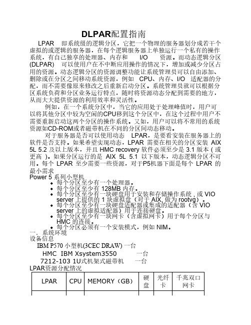
DLPAR配置指南LPAR 即系统级的逻辑分区,它把一个物理的服务器划分成若干个虚拟的或逻辑的服务器,在每个逻辑服务器上单独运行一个私有的操作系统,有自己独享的处理器、内存和I/O 资源。
而动态逻辑分区(DLPAR) 可以使用户在不中断应用操作的情况下,增加或减少分区占用的资源。
动态逻辑分区的资源调整功能让系统管理员可以自由添加、删除或在分区之间移动系统资源,例如CPU、内存、I/O 适配器的分配,而不需要像原来修改之后重新启动分区。
系统管理员就可以根据分区系统负荷和分区业务运行特点,随时将资源动态分配到需要的地方,从而大大提供资源的利用效率和灵活性。
例如,在一个系统分区中,当它的应用处于处理峰值时,用户可以将其他分区中较为空闲的CPU移到这个分区中,在这个过程中用户不需要重新启动这两个分区的操作系统。
又如,用户可以将不常用的系统资源如CD-ROM或者磁带机在不同的分区间动态移动。
对于服务器是否可以使用动态LPAR,是要看安装在服务器上的软件是否支持。
如果希望实现动态,LPAR 需要在相关的分区安装AIX 5L 5.2 及以上版本,并且HMC recovery 软件必须至少是3.1 版本( 或更高)。
如果分区运行的是AIX 5L 5.1 以下版本,动态逻辑分区不可用。
每个LPAR 至少需要一些资源,对于P5机器下面是每个LPAR 的最小需求Power 5 系列小型机∙每个分区至少有一个处理器。
∙每个分区至少有128MB 内存。
∙每个分区至少有一块硬盘用于安装和存储操作系统, 或VIO server 上提供的1 块虚拟盘(对于AIX, 做为rootvg)。
∙每个分区至少有一块硬盘适配器或集成的适配器(含VIO server 上的虚拟适配器)用于连接硬盘。
∙每个分区至少有一块网卡(含虚拟网卡)用于每个分区与HMC 的连接。
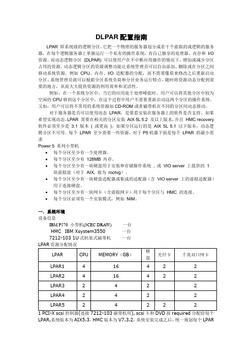
∙每个分区必须有一个安装模式,例如NIM。
一.系统环境设备信息IBM P570 小型机(3CEC DRAW) 一台HMC IBM Xsystem3550 一台7212-103 1U式机架式磁带机一台LPAR,系统版本为AIX5.3,HMC版本为V7.3.2,系统安装完成之后,统一规划每个LPAR的ent3为DLPAR的通信端口,地址规划为与HMC控制口不同网断,建议DLPAR利用单独的hub来实施,地址分别为:HMC IP地址172.1.50.1LPAR1IP地址 172.1.50.51LPAR2 IP地址 172.1.50.52LPAR3 IP地址 172.1.50.53LPAR4 IP地址 172.1.50.54LPAR5 IP地址 172.1.50.55二.配置DLPAR要求1.建议将HMC控制台的版本升级到3.24以上,本次实验HMC版本为V7.3.2。
vio实施

目录第1章前言 (3)1.1参考文档 (3)1.2注意事项 (3)第2章用户需求 (4)第3章硬件安装 (5)第4章实施准备 (6)4.1硬件准备: (6)4.2软件准备: (6)第5章VIOS配置 (8)5.1创建SHARE PRECESSOR POOL (8)5.2创建VIO S ERVER (9)5.3VIOS的升级: (15)第6章创建虚拟设备 (17)6.1创建VSCSI设备 (17)6.2创建虚拟光纤卡设备 (18)第7章VIO 客户端设置 (19)第8章VSCSI与NPIV配置 (20)8.1V SCSI在VIOS上的配置 (20)8.2NPIV在VIOS上的配置 (20)8.3NPIV在VIO C IENT上的配置 (21)8.4NPIV在SAN S WITCH上的配置 (21)8.5NPIV的SAN BOOT支持 (21)第1章前言1.1参考文档IBM System p Advanced POWER Virtualization (PowerVM) Best Practicespdfsg247590IBM PowerVM Virtualization Managing and Monitoring.pdf1.2注意事项文档中的截图,会与在项目实施中有所差异,只用作实施中的参考,请以文字说明为准。
第2章 用户需求用户硬件环境与根据用户应用需求(用户提供)VIOS:2.1.3.10-FP23, AIX6105SP1 硬件类别 分区 组件分区1 SAP Retail 数据库生产服务器分区2 SAP Retail 应用生产服务器1分区3 SAP AFS 数据库生产服务器生产环境服务器分区4 SAP AFS 应用生产服务器1分区5 SAP BI 数据库生产服务器分区6 SAP BI 应用生产服务器 (备)分区1 SAP Retail 数据库生产服务器 (备)分区2 SAP Retail 应用生产服务器2分区3 SAP AFS 数据库生产服务器 (备)生产环境服务器分区4 SAP AFS 应用生产服务器2分区5 SAP BI 数据库生产服务器 (备)分区6 SAP BI 应用生产服务器分区1 SAP Retail 数据库、应用开发服务器分区2 SAP AFS 数据库、应用开发服务器开发环境服务器分区3 SAP BI 数据库、应用开发服务器分区1 SAP Retail 数据库、应用测试服务器分区2 SAP AFS 数据库、应用测试服务器测试环境服务器分区3 SAP BI 数据库、应用测试服务器VIO规划见附件第3章 硬件安装根据用户机房环境安装项目中的E4AX2,EMAX2,DS5020,B40X2.第4章 实施准备4.1硬件准备:HMC、相关连接线。
SiFive HiFive Unleashed 初学者指南 v1p0说明书

SiFive HiFive Unleashed Getting Started Guidev1p0© SiFive, Inc.SiFive HiFive Unleashed Getting Started GuideProprietary NoticeCopyright © 2018, SiFive Inc. All rights reserved.Information in this document is provided “as is”, with all faults.SiFive expressly disclaims all warranties,representations and conditions of any kind,whether ex-press or implied,including,but not limited to,the implied warranties or conditions of merchantabil-ity, fitness for a particular purpose and non-infringement.SiFive does not assume any liability rising out of the application or use of any product or circuit, andspecifically disclaims any and all liability,including without limitation indirect,incidental,spe-cial,exemplary, or consequential damages.SiFive reserves the right to make changes without further notice to any products herein. Release InformationVersion Date Changesv1p0March 09, 2018•Initial releaseContents1Required Hardware (2)2Optional Hardware (3)3Board Setup (4)4Boot and Run (8)4.1Connecting with ssh (8)4.2Connecting with USB console (8)4.3Knobs on the HiFive/Unleashed (9)4.4HiFive/Unleashed Boot (9)5Connector Pinout (11)5.1FMC Connector (11)5.2Low Speed IO Expansion Connectors (15)5.3MicroUSB Connector (16)5.4MicroSD Card Connector (16)5.5JTAG Connector (16)Chapter 1Required HardwareUsing the HiFive Unleashed Development Kit requires the following hardware:HiFive Unleashed Development KitSiFive’s HiFive Unleashed development kit is based around the Freedom U540-C000chip,the world’s first 4+1 multi-core RISC-V Linux capable SoC. It can be purchased from Crowd Supply: /sifive/hifive-unleashedUSB A to Micro-B CableAny standard USB Type A Male to Micro-B Male cable can be used to interface with the HiFive Unleashed./usb-a-to-micro-b-cable12V DC Power Wall AdapterThe HiFive Unleashed Development Kit requires an external12V,2A power supply.When not powering directly from the FMC expansion module,a12V DC Wall Adapter with a5.5outer di-ameter,2.5mm center-positive barrel plug,must be plugged into J8on the Development Kit.If powering directly from the FMC expansion module,then unplug the12DC power wall adapter from the development kit. Power should not be supplied from 2 different external sources.Chapter 2Optional HardwareEthernet CableHiFive Unleashed Development Kit has an RJ45Ethernet port that enables the FU540-C000to connect to an 10/100/1000 Base-T network.FMC Expansion Carrier CardAdditional functionality can be added to the HiFive Unleashed Development Kit through the FMC connector.The FMC expansion carrier card typically has an FPGA to enable third-party develop-ers to add new logic to the development kit.The HiFive Unleashed Development Kit can be directly powered from the FMC expansion carrier card.When powering from the FMC expansion carrier card,do not plug in the12V DC adapter into the HiFive Unleashed.Chapter 3Board SetupTo prepare the board for use, follow these steps:•Unplug the HiFive/Unleashed and switch the power off(red button sticking out).The board is still powered even when the switch is off, so handle with care whenever power is applied.•Ensure the fan is plugged in.•Set all pins in the DIP-switch block to the LEFT.The ON position=0;therefore,this sets MSEL to mode 1111. See the boot modes table in next section for more information on MSEL.•Insert an SD-card programmed with bbl+linux.The github repository sifive/freedom-u-sdk produces an image suitable for writing to a partition with GUID type 2E54B353-1271-4842-806F-E436D6AF6985.•If available,connect the board to a network switch.The board will run DHCP on boot and start an ssh server.The MAC address is70:b3:d5:92:fX:XX,where X:XX is replaced by the board number converted to hexadecimal.For example,if the board is H5U-00063,then the last digits of the MAC address are0:3f.•If available,connect the board via USB to a developer machine.The USB connector has two serial interfaces.The first contains the linux console running at115200Hz.The second pro-vides JTAG suitable for use with openocd.•Plug in the HiFive/Unleashed; the fan should begin to spin.•Turn on the HiFive/Unleashed; after 30s a LED should begin to regularly blink a heartbeat.Chapter 4Boot and RunFollow the steps from the previous section to power on the board.Once the heartbeat LED is pulsing regularly, you can connect to the board.There are two ways to connect to the HiFive/Unleashed:ssh and serial.The serial interface is slower and cannot receive files, so ssh is recommended.4.1Connecting with sshOn power-on,the default freedom-u-sdk image obtains an IP address from DHCP and starts an ssh server.The MAC address of the board is70:b3:d5:92:fX:XX,where X:XX is replaced by the board number converted to hexadecimal.Ask your network administrator which IP address your board has obtained. Add the following to your.ssh/config, filling in the IP address:Host hifiveuHostName xxx.yyy.zzz.aaaUser rootStrictHostKeyChecking noUserKnownHostsFile /dev/nullTo connect, run ssh hifiveu. The password is sifive.4.2Connecting with USB consoleWith a USB cable connected to the HiFive/Unleashed,you can access the console.The console both shows the linux boot process and can be used to log in to the device.From Mac OS, run:sudo screen /dev/bserial-*01 115200From Linux, run:sudo screen /dev/serial/by-path/*-port0 115200Hit enter a few times to see the login prompt. Username root, password sifive.To quit screen,hit Control-a,\,y.If you do not quit properly,you can end up with multiple screens running at the same time. This manifests as lost characters both sent and received.4.3Knobs on the HiFive/UnleashedSD cards formatted by the freedom-u-sdk contains a second partition which can be used for persistent storage.You can access this storage by executing mount/dev/mmcblk0p2/mnt. However, the linux mmc_spi driver is extremely slow, so this should not be used for large files. Report core frequency:echo $(cat /sys/devices/platform/soc/10000000.prci/rate)4.4HiFive/Unleashed BootThe Freedom U500 supports several boot methods. The general flow follows multiple stages:1.ROM0(0x1004):Decode MSEL and jump to the address found in0x1100+8*MSEL.For MSEL > 4, the process proceeds to the next step.2.ROM1(0x1_0000):Decode MSEL to determine which media contains the First StageBoot Loader(FSBL).The media is expected to be formatted with a GPT partitiontable(even on SPI flash).The entire contents of the first partition with GUID type5B193300-FC78-40CD-8002-E86C45580B47are downloaded into the L2sidebandmemory and execution transfers there.ROM1contains a hard-coded DTB blockpassed in a1to the FSBL, which ignores it.3.FSBL(0x800_0000):Initialize core PPLs,DDR,and Ethernet PHY.Decode MSEL todetermine which media contains the Berkeley Boot Loader(BBL).The media is ex-pected to contain a GPT-formatted partition table.The contents of the first partitionwith GUID type2E54B353-1271-4842-806F-E436D6AF69851are downloaded intoDDR memory and execution transfers there.The FSBL contains an embedded DTBdescribing both the Freedom U500SoC and HiFive/Unleashed board.The DTB isupdated with the board MAC address and DDR capacity and passed to BBL in a1.4.BBL(0x8000_0000):Initialize the RISC-V supervisor binary interface(SBI).Jump tothe embedded linux kernel payload, passing a redacted DTB in a1.5.Linux (0xffff_ffe0_0000_0000): Initializes all devices, starts DHCP + ssh.Both ROM1and the FSBL find the next boot loader stage based on the MSEL setting.All possible values are enumerated below.The three SPI interfaces on the Freedom U500SoC can be used to download media either from SPI flash(using x4data pins or x1)or an SD card,using the SPI protocol.ROM1downloads the FSBL at10MHz,while the FSBL uses50MHz for SPI and20MHz for SD.MSEL FSBL BBL Purpose0000--loops forever waiting for debugger0001--jump directly to 0x2000_0000 (memory-mapped SPI0)0010--jump directly to 0x3000_0000 (memory-mapped SPI1)0011--jump directly to 0x4000_0000 (uncached ChipLink)0100--jump directly to 0x6000_0000 (cached ChipLink)0101SPI0 x1SPI0 x1-0110SPI0 x4SPI0 x4Rescue image from flash (preprogrammed)0111SPI1 x4SPI1 x4-1000SPI1 SD SPI1 SD-1001SPI2 x1SPI2 x1-1010SPI0 x4SPI1 SD-1011SPI2 SD SPI2 SD Rescue image from SD card1100SPI1 x1SPI2 SD-1101SPI1 x4SPI2 SD-1110SPI0 x1SPI2 SD-1111SPI0 x4SPI2 SD Default boot modeChapter 5Connector Pinout5.1FMC ConnectorHiFive Unleashed has an VITA57FPGA Mezzanine Card(FMC)HPC connector(Samtec ASP-134602-01)to connect to an FPGA on an FMC carrier card(mating connector:Samtec ASP-134486-01).The communication interface between the HiFive Unleashed and the FPGA is ChipLink.The HiFive Unleashed can be powered directly from the FMC carrier card through the FMC connector.11Pin Name Voltage Rail Direction FMC Pin Number CHIPLINK_RX_CLK 1.8V INPUT G2CHIPLINK_RX_RST 1.8V INPUT G37CHIPLINK_RX_SEND 1.8V INPUT G36CHIPLINK_RX_DAT0 1.8V INPUT D20CHIPLINK_RX_DAT1 1.8V INPUT D21CHIPLINK_RX_DAT2 1.8V INPUT C22CHIPLINK_RX_DAT3 1.8V INPUT C23CHIPLINK_RX_DAT4 1.8V INPUT H22CHIPLINK_RX_DAT5 1.8V INPUT H23CHIPLINK_RX_DAT6 1.8V INPUT G21CHIPLINK_RX_DAT7 1.8V INPUT G22CHIPLINK_RX_DAT8 1.8V INPUT H25CHIPLINK_RX_DAT9 1.8V INPUT H26CHIPLINK_RX_DAT10 1.8V INPUT G24CHIPLINK_RX_DAT11 1.8V INPUT G25CHIPLINK_RX_DAT12 1.8V INPUT D23CHIPLINK_RX_DAT13 1.8V INPUT D24CHIPLINK_RX_DAT14 1.8V INPUT H28CHIPLINK_RX_DAT15 1.8V INPUT H29CHIPLINK_RX_DAT16 1.8V INPUT G27CHIPLINK_RX_DAT17 1.8V INPUT G28CHIPLINK_RX_DAT18 1.8V INPUT D26CHIPLINK_RX_DAT19 1.8V INPUT D27CHIPLINK_RX_DAT20 1.8V INPUT C26CHIPLINK_RX_DAT21 1.8V INPUT C27CHIPLINK_RX_DAT22 1.8V INPUT H31CHIPLINK_RX_DAT23 1.8V INPUT H32CHIPLINK_RX_DAT24 1.8V INPUT G30CHIPLINK_RX_DAT25 1.8V INPUT G31CHIPLINK_RX_DAT26 1.8V INPUT H34CHIPLINK_RX_DAT27 1.8V INPUT H35CHIPLINK_RX_DAT28 1.8V INPUT G33CHIPLINK_RX_DAT29 1.8V INPUT G34CHIPLINK_RX_DAT30 1.8V INPUT H37CHIPLINK_RX_DAT31 1.8V INPUT H38CHIPLINK_TX_CLK 1.8V OUTPUT H4CHIPLINK_TX_RST 1.8V OUTPUT G19CHIPLINK_TX_SEND 1.8V OUTPUT G18CHIPLINK_TX_DAT0 1.8V OUTPUT G6CHIPLINK_TX_DAT1 1.8V OUTPUT G7CHIPLINK_TX_DAT2 1.8V OUTPUT D8CHIPLINK_TX_DAT3 1.8V OUTPUT D9Table 1:FMC Connector PinoutPin Name Voltage Rail Direction FMC Pin Number CHIPLINK_TX_DAT4 1.8V OUTPUT H7CHIPLINK_TX_DAT5 1.8V OUTPUT H8CHIPLINK_TX_DAT6 1.8V OUTPUT G9CHIPLINK_TX_DAT7 1.8V OUTPUT G10CHIPLINK_TX_DAT8 1.8V OUTPUT H10CHIPLINK_TX_DAT9 1.8V OUTPUT H11CHIPLINK_TX_DAT10 1.8V OUTPUT D11CHIPLINK_TX_DAT11 1.8V OUTPUT D12CHIPLINK_TX_DAT12 1.8V OUTPUT C10CHIPLINK_TX_DAT13 1.8V OUTPUT C11CHIPLINK_TX_DAT14 1.8V OUTPUT H13CHIPLINK_TX_DAT15 1.8V OUTPUT H14CHIPLINK_TX_DAT16 1.8V OUTPUT G12CHIPLINK_TX_DAT17 1.8V OUTPUT G13CHIPLINK_TX_DAT18 1.8V OUTPUT D14CHIPLINK_TX_DAT19 1.8V OUTPUT D15CHIPLINK_TX_DAT20 1.8V OUTPUT C14CHIPLINK_TX_DAT21 1.8V OUTPUT C15CHIPLINK_TX_DAT22 1.8V OUTPUT H16CHIPLINK_TX_DAT23 1.8V OUTPUT H17CHIPLINK_TX_DAT24 1.8V OUTPUT G15CHIPLINK_TX_DAT25 1.8V OUTPUT G16CHIPLINK_TX_DAT26 1.8V OUTPUT D17CHIPLINK_TX_DAT27 1.8V OUTPUT D18CHIPLINK_TX_DAT28 1.8V OUTPUT C18CHIPLINK_TX_DAT29 1.8V OUTPUT C19CHIPLINK_TX_DAT30 1.8V OUTPUT H19CHIPLINK_TX_DAT31 1.8V OUTPUT H20RESET_N 1.8V Open Drain H5VDD_DCIN12V Voltage In-putC35, C37VDD_1V8 1.8V VoltageOutputH1PG_M2C Open Drain Open Drain F1 PRSNT_M2C_L GND Open Drain H2GND GND GND A1, A4, A5, A8, A9, A12, A13, A16, A17, A20, A21, A24, A25, A28, A29, A32, A33, A36, A37, A40, B2, B3, B6, B7, B10, B11, B14, B15, B18, B19, B22, B23, B26, B27, B30, B31, B34, B35, B38, B39, C1, C4, C5, C8, C9, C12, C13, C16, C17, C20, C21, C24, C25, C28, C29, C32, C33,Pin Name Voltage Rail Direction FMC Pin NumberC36, C38, C40, D2, D3, D6, D7,D10, D13, D16, D19, D22, D25,D28, D37, D39, E1, E4, E5, E8,E11, E14, E17, E20, E23, E26,E29, E32, E35, E38, E40, F2, F3,F6, F9, F12, F15, F18, F21, F24,F27, F30, F33, F36, F39, G1, G4,G5, G8, G11, G14, G17, G20,G23, G26, G29, G32, G35, G38,G40, H3, H6, H9, H12, H15, H18,H21, H24, H27, H30, H33, H36,H39, J1, J4, J5, J8, J11, J14,J17, J20, J23, J26, J29, J32, J35,J38, J40, K2, K3, K6, K9, K12,K15, K18, K21, K24, K27, K30,K33, K36, K39Pin and Signal DescriptionCHIPLINK_RX_CLK: ChipLink Receive Clock from the FMC carrier card to HiFive Unleashed. CHIPLINK_RX_RST: ChipLink Receive Reset from the FMC carrier card to HiFive Unleashed. CHIPLINK_RX_SEND:ChipLink Receive Send strobe from the FMC carrier card to HiFive Un-leashed.CHIPLINK_RX_DATA[31:0]:ChipLink Receive Data bus from the FMC carrier card to HiFive Un-leashed.CHIPLINK_TX_CLK: ChipLink Transmit Clock from HiFive Unleashed to the FMC carrier card. CHIPLINK_TX_RST: ChipLink Transmit Reset from HiFive Unleashed to the FMC carrier card. CHIPLINK_TX_SEND:ChipLink Transmit Send strobe from HiFive Unleashed to the FMC carrier card.CHIPLINK_TX_DATA[31:0]:ChipLink Transmit Data bus from HiFive Unleashed to the FMC car-rier card.RESET_N:Bidirectional,Open Drain active-low system-level reset.Either the HiFive Unleashed or the FMC carrier card can initiate a system level reset by pulling this pin low.The pull up resistor is on the HiFive Unleashed.VDD_DCIN: 12V voltage rail from the FMC carrier card to HiFive Unleashed.VDD_1V8: 1.8V IO voltage from HiFive Unleashed to the FMC carrier card.PG_M2C:Open-drain,active high power good signal to indicate that HiFiveUnleashed has pow-ered up correctly. The pull up resistor is on the FMC carrier card.PRSNT_M2C_L:Active-low signal to indicate to the FMC carrier card that HiFive Unleashed is present. The pull up resistor is on the FMC carrier card.All other pins are No Connect on the FMC connector.5.2Low Speed IO Expansion ConnectorsThere are two Low Speed IO Expansion connectors,a2mm pitch2x20and a2mm pitch2x10 female headers.The2x20connector follows the96Boards EE Specification Expansion Connector pinout.All IO voltage are at 1.8V.Net Name Pin Name##Pin Name Net NameGND GND12GND GNDNo Connect UART0_CTS34PWR_BTN_N PWR_BTN_NUART0_TX UART0_TXD56RST_BTN_N RESET_NUART0_RX UART0_RXD78SPI0_SCLK QSPI1_SCKNo Connect UART0_RTS910SPI0_DIN QSPI1_DQ1UART1_TX UART1_TXD1112SPI0_CS QSPI1_CS0UART1_RX UART1_RXD1314SPI0_DOUT QSPI1_DQ0I2C0_SCL I2C0_SCL1516PCM_FS No ConnectI2C0_SDA I2C0_SDA1718PCM_CLK No ConnectNo Connect I2C1_SCL1920PCM_DO No ConnectNo Connect I2C1_SDA2122PCM_DI No ConnectGPIO0GPIO-A2324GPIO-B GPIO1GPIO2GPIO-C2526GPIO-D GPIO3GPIO4GPIO-E2728GPIO-F GPIO5GPIO6GPIO-G2930GPIO-H GPIO7GPIO8GPIO-I3132GPIO-J GPIO9GPIO15GPIO-K3334GPIO-L No ConnectVDD_1V8+1V83536SYS_DCIN VDD_DCINVDD_5V0+5V3738SYS_DCIN VDD_DCINGND GND3940GND GNDTable 2:2x20 Low Speed IO Expansion Connector PinoutThe 2x10 connector has additional low speed IOs. All IO voltage are at 1.8V.Net Name Direction##Direction Net NamePWM0_0OUTPUT12OUTPUT PWM0_2PWM0_1OUTPUT34OUTPUT PWM0_3GEMGXL_RST (Reset toOUTPUT56BIDIRECTIONAL QSPI1_DQ2 Ethernet PHY)FASTLINK_FAIL (OutputOUTPUT78BIDIRECTIONAL QSPI1_DQ3 from Ethernet PHY)EN_VDD_SD (EnableOUTPUT910OUTPUT QSPI1_CS1 Power to SD Card)SD_CD (SD Card De-OUTPUT1112OUTPUT QSPI1_CS2 tect)(NC)NC1314OUTPUT QSPI1_CS3PWM1_0OUTPUT1516GND GNDPWM1_1OUTPUT1718OUTPUT PWM1_2GND GND1920OUTPUT PWM1_3Table 3:2x10 Low Speed IO Expansion Connector Pinout5.3MicroUSB ConnectorThe MicroUSB connector provides a connection to UART0and JTAG from a Host PC.If needed, drivers for the FTDI FT2232H can be found at:/FTDrivers.htm5.4MicroSD Card ConnectorThe MicroSD card connector enables adding more storage with an external MicroSD card.The connector is accessible from the Freedom U540 through SPI0.5.5JTAG ConnectorThe JTAG connector is a1.27mm pitch2x5male header(SAMTEC FTSH-105or equivalent) that is complaint to the RISC-V External Debug Support V0.13 specification.More information about the RISC-V External Debug can be found at:https:///documentation/risc-v/risc-v-external-debug-supportPin Name##Pin NameTCK12GNDTDO34VCCTMS56SRSTn(NC)78(TRSTn/NC)TDI910GNDTable 4:JTAG Connector Pinout。
- 1、下载文档前请自行甄别文档内容的完整性,平台不提供额外的编辑、内容补充、找答案等附加服务。
- 2、"仅部分预览"的文档,不可在线预览部分如存在完整性等问题,可反馈申请退款(可完整预览的文档不适用该条件!)。
- 3、如文档侵犯您的权益,请联系客服反馈,我们会尽快为您处理(人工客服工作时间:9:00-18:30)。
Partition Resource for VIO LPAR
1. HMC connect to Pserver.HMC eth0 as a DHCP server, P5's HMC1 Port as Client.
If one HMC managed multi-P systems, can add 1 HUB or Switch between HMC and P systems.
HMC eth0 DHCP pool: 10.*.*.* or 192.*.*.*
P5's eth0: ip= 9.*.*.*
网上收P5连接HMC
2. Create 1 VIO Server Logical Partition. In HMC Interface Point to Configuration: click VIO Server;
/pod/pod到这里输入机器的型号和序列号,查看VET information.
3. Change Partition ID: 1 Partition Name: VIOSrv1, Next;
4. Profile Name:Default, point to Next;或者编辑成其他相关名字;
5. Shared,and Next;
6. Minimum Processing Units: 0.1以0.1为单位,最小
Desired processing Units: 0.2期望值
Maximum processing units:0.3最大值;
Minimum virtual processors: 1最小的VP,整数值
Desired virtual processors: 2期望
Maximum virtual processors:3最大
Uncapped: Checked. Weight: 192.0数值越高,优先级别越高;
7. Minimum memory: 128 MB最小内存
Desired memory: 1 G期望内存
Maximum memory: 2G最大内存
8. Check P5 all IO devies;
Choose "Storage controller&PCI Ethernet&Other Mass Storage Controller" as required IO resources.
Next;或者所有设备都选为Desired.
9. Maximum virtual adapters: 100
Actions--create--Ethernet Adapter…建立虚拟网卡Adapter ID: 11
VLAN ID: 1
Access external network: checked. Press OK.
Actions-Create-SCSI建立虚拟的SCSI为其他LPAR
建立VSCSI Adapter 给其他Vlpar.
Virtual SCSI Adapter for CDROM
Actions--Create--SCSI Adapter…
Adapter: 60光驱的VSCSI Choose any client partition can connect
Virtual SCSI Adapter for LPAR2
Actions--Create--SCSI Adapter…
Adapter: 20
Choose Only selected partition can connect
Client Partition ID: 2
Client adapter ID: 21
Virtual SCSI Adapter for LPAR3
Actions--Creae--SCSI Adapter…
Adapter: 30
Choose Only selected partition can connect
Client Partition ID: 3
Client adapter ID: 21
10. Next and finish,VIO 划分完成
Install and Configure VIO Servers
1. Install VIO Server.
Activate VIO Server;
Partition profiles: default
Check Open a terminal window or console session.
Click Advanced:
Boot Mode: Choose SMS.Press Ok to start install VIO Server(put VIO Server CD to P serve 3. Login in VIO Server, id: padmin$license -accept。
