远翔(飞凌)单片机MCU选型与规格书下载
飞凌OK210硬件手册说明书
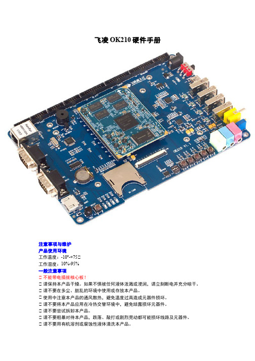
飞凌OK210硬件手册注意事项与维护产品使用环境工作温度:-10°-+75℃工作湿度:10%-95%一般注意事项℃ 不能带电插拔核心板!℃ 请保持本产品干燥。
如果不慎被任何液体泼溅或浸润,请立刻断电并充分晾干。
℃ 请不要在多尘、脏乱的环境中使用或存放本产品。
℃ 使用中注意本产品的通风散热,避免温度过高造成元器件损坏。
℃ 请不要将本产品应用在冷热交替环境中,避免结露损坏元器件。
℃ 请不要尝试拆卸本产品。
℃ 请不要粗暴对待本产品,跌落、敲打或剧烈晃动都可能损坏线路及元器件。
℃ 请不要用有机溶剂或腐蚀性液体清洗本产品。
℃ 请不要用颜料涂抹本产品。
℃ 擅自修改或使用未经授权的配件可能损坏本产品,由此造成的损坏将不给予保修。
如果产品出现故障,请联系飞凌技术服务部。
版权声明本手册所有权由保定市飞凌嵌入式有限公司独家持有。
未经本公司的书面许可,任何单位和个人无权以任何形式复制、传播、转载本手册的任何部分,否则一切后果由违者自负。
技术支持与更新技术支持说明技术支持范围:开发板软、硬件资源;判断开发板是否存在故障;如何烧写和更新系统;如何测试和运行开发板提供的程序。
技术支持时间:周一到周五:9:00—11:30,13:30—17:00。
公司按照国家法定节假日安排休息,在此期间无法提供技术支持,有问题请在论坛发帖。
保修范围及内容说明:1.凡飞凌出售的产品,除特殊说明外,提供一年的保修服务,(液晶屏提供三个月质保)。
2.保修期间凡产品出现质量问题,均可享受飞凌的免费维修服务,运费由双方均摊。
3.保修期满后出现性能故障和硬件问题,可与飞凌取得联系,飞凌提供有偿的维修服务,视具体情况而定。
注:凡是不在免费保修范围之内,邮费由客户来承担。
如客户不能提供购买时间的凭证,将开发板出厂日期视为购买日期。
维修周期:收到需维修的产品后,安排维修工程师测试、维修。
一般七个工作日即可修好(不包括邮寄路途上的时间)。
如有特殊情况,会向客户说明再与客户协商处理。
飞凌嵌入式OK335x硬件手册
飞凌OK6410-A开发板硬件手册
一.OK6410开发板简介随着微电子技术的快速发展,ARM处理器经历了包括ARM7、ARM9在内的多个发展历程,而ARM11的成熟应用必将为嵌入式的发展带来新的活力,使更高端的产品应用成为可能。
与ARM9的5级流水线相比,ARM11拥有一条具有独立的load-store和算术流水的8级流水线,在同样工艺下,ARM11处理器的性能与ARM9相比大约提高了40%。
ARM11执行ARMv6架构的指令,ARMv6指令包含了针对媒体处理的单指令流多数据流(SIMD)扩展,采用特殊的设计,以改善视频处理性能。
为了能够进行快速浮点运算,ARM11增加了向量浮点单元。
所有这些结构上的提高,都是ARM9处理器不可比拟的。
ARM11为便携式和无线应用,提供了从未有过的高超性能,并且使我们主要关心的成本和功耗减到最小。
ARM11的微架构保证了系统性能可以从基本的350-500MHz范围扩展到最终的1GHz以上。
其微架构的高效率表现,允许开发者根据不同的应用来调节时钟频率和电源电压,从而在性能和功耗之间达到最佳的折衷。
例如,一个基于ARM11的微架构的处理器在1.2V工作电压下,使用0.13um工艺实现,其功率将不会超过0.4mW/MHz。
ARM11微处理器是一种高性能、低功耗的‘准64位’微处理器!对于目前大多数嵌入式应用,一个真正的64位处理器仍然被认为是不必要的,其巨大的功耗和面积让人难以接受。
对此,ARM11选择了一个折中的方案,以较小的代价,部分实现了一个64位微架构。
ARM11只在处理器整数单位和高速缓存之间,以及在整数单位和协处理器之间实现了64位数据总线。
这些64位数据道路允许处理器在一个时钟周期中同时获取两条指令,还允许在一个时钟周期执行多个数据读写指令这使得ARM11在执行很多特定序列的代码时能够达到非常高的性能,特别是那些允许数据搬移与数据处理并行处理的代码序列。
S3C6410是由三星公司推出的一款低功耗、高性价比的RSIC处理器,它基于ARM11内核(ARM1176JZF-S),可广泛应用于移动电话和通用处理等领域;S3C6410为2.5G和3G通信服务提供了优化的硬件性能,内置强大的硬件加速器:包括运动视频处理、音频处理、2D加速、显示处理和缩放等;集成了一个MFC(Multi-Format video Codec)支持MPEG4 /H.263/H.264编解码和VC1的解码,能够提供实时的视频会议以及NRSC和PAL制式的TV输出;除此之外,该处理器内置一个采用最先进技术的3D加速器,支持OpenGL ES 1.1/ 2.0和D3DM API,能实现4M triangles/s的3D加速;同时,S3C6410包含了优化的外部存储器接口,该接口能满足在高端通信服务中的数据带宽要求。
Cmsemicon cms8s588x 增强型闪存8位1T 8051微控制器 数据手册说明书

CMS80F251x数据手册ArrayCMS8S588x数据手册增强型闪存8位1T 8051微控制器Rev.1.0.2请注意以下有关CMS知识产权政策*中微半导体(深圳)股份有限公司(以下简称本公司)已申请了专利,享有绝对的合法权益。
与本公司MCU或其他产品有关的专利权并未被同意授权使用,任何经由不当手段侵害本公司专利权的公司、组织或个人,本公司将采取一切可能的法律行动,遏止侵权者不当的侵权行为,并追讨本公司因侵权行为所受的损失、或侵权者所得的不法利益。
*中微半导体(深圳)股份有限公司的名称和标识都是本公司的注册商标。
*本公司保留对规格书中产品在可靠性、功能和设计方面的改进作进一步说明的权利。
然而本公司对于规格内容的使用不负责任。
文中提到的应用其目的仅仅是用来做说明,本公司不保证和不表示这些应用没有更深入的修改就能适用,也不推荐它的产品使用在会由于故障或其它原因可能会对人身造成危害的地方。
本公司的产品不授权适用于救生、维生器件或系统中作为关键器件。
本公司拥有不事先通知而修改产品的权利,对于最新的信息,请参考官方网站。
1. 产品特性1.1 功能特性◆兼容MCS-51的1T指令系统- 系统时钟频率最高支持48MHz- 机器周期最快支持1T SYS @ F SYS≤24MHz - 机器周期最快支持2T SYS @ F SYS=48MHz ◆内存- 程序FLASH:32K×8Bit- Data FLASH:1K×8Bit- 通用RAM:256×8Bit- 通用XRAM:2K×8Bit- 支持BOOT功能区,1K/2K/4K可选- 程序FLASH支持分区保护◆4种振荡方式- HSI-内部高速振荡:48MHz- HSE-外部高速振荡:8MHz/16MHz- LSE-外部低速振荡:32.768KHz- LSI-内部低速振荡:125KHz◆GPIO- 最多可达30个GPIO- 均支持上/下拉电阻功能- 均支持边沿(上升沿/下降沿/双沿)中断- 均支持唤醒功能◆中断源- 支持所有的外部端口中断- 7个定时器中断- 其它外设中断◆定时器- WDT定时器(看门狗定时器)- Timer0/1,Timer2,Timer3/4- LSE_Timer(支持休眠唤醒功能)- WUT(唤醒定时器)- BRT(串口波特率时钟发生器)◆循环冗余校验单元- CRC16(CRC16-CCITT)◆蜂鸣器驱动- 50%占空比,频率可自由设置◆PWM- 6通道PWM- 6个相互独立周期计数器- 支持独立/互补/同步/成组模式- 支持边沿对齐方式- 支持互补模式死区延时功能◆通信模块- 1xSPI(通讯速率最高可达6Mb/s)- 1xI2C(通讯速率最高可达400Kb/s)- 2xUART(波特率最高可达1Mb/s)- UART1可任意GPIO映射◆工作电压范围- 2.1V~5.5V◆工作温度范围- -40℃~105℃◆低压复位功能(LVR)- 1.8V/2.0V/2.5V/3.5V◆低压检测功能(LVD)- 2.0V~4.3V 8级可选◆高精度12位ADC- 最多可达30个AD外部通道- 参考电压可选(1.2V/2.0V/2.4V/3.0V/VDD)- 可检测内部1.2V基准电压- 支持硬件触发启动转换功能- 支持一组结果数字比较功能◆低功耗模式- 空闲模式(IDLE)- 休眠模式(STOP)◆支持96位唯一ID号(UID)- 每颗芯片有独立的ID号◆支持两线串行编程与调试1.2 产品对比注:(1)通过系统配置寄存器设置APROM和BOOT空间大小,APROM与BOOT空间总共最大为32K。
SmartPRO编程器编程Spansion的MCU产品应用手册说明书
广州致远电子股份有限公司文件信息类别内容关键词SmartPRO 通用编程器 Spansion FUJITSU MCU摘要本文介绍如何使用SmartPRO 系列通用编程器来编程Spansion 的MCU 芯片。
SmartPRO 编程器编程Spansion 的MCU修订历史版本日期原因V1.00 2008/09/01 创建文档。
V1.01 2009/10/10 将文档中图片修改为SmartPRO 2008版软件截图V1.02 2014/07/23 更改半导体公司名称、修改错别字目录1.Spansion的MCU芯片支持情况 (1)2.Spansion的MCU芯片特点 (2)2.1 加密特点 (2)2.2 NVR区 (2)3.应用软件界面简介 (3)4.烧录器件的步骤 (4)4.1 选择器件 (4)4.2 将数据装入缓冲区 (5)4.3 设置芯片配置信息及加密选项 (6)4.4 编程芯片 (6)4.5 组合定制 (7)4.6 量产 (7)5.脱机模式 (9)5.1 脱机操作说明 (9)5.1.1 键盘使用规则 (9)5.1.2 菜单介绍 (9)5.1.3 创建脱机工程 (9)1.制作脱机工程 (9)2.填写工程信息 (10)3.选择存储介质 (10)5.2 脱机操作步骤 (10)6.免责声明 (13)1. Spansion的MCU芯片支持情况目前,在SmartPRO 5000U-Plus和SmartPRO T9000-PLUS 编程器上均支持52种Spansion(原FUJITSU)的MCU芯片(包含封装),包括F2MC-8FX系列, F2MC-8L系列,F2MC-16LX系列和F2MC-16FX系列。
详细情况见表 1.1。
表 1.1 FUJITSU 芯片支持情况Series Part Number Adapter Part Number AdapterF2MC-8FX MB95F108AMWPFM@QFP64ZY514E MB95F203K@SOP20 ZY308A MB95F108AHWPFM@ QFP64ZY514E MB95F203H@SDIP24 ZY403A MB95F108PFV@ QFP64 ZY565B MB95F203K@SDIP24 ZY403A MB95F118ASPMT@QFP48 ZY509A MB95F204H@SOP20 ZY308A MB95F118NSPMC@LQFP52ZY552D MB95F204K@SOP20 ZY308A MB95F128MBPMC@LQFP100ZY515A MB95F204H@SDIP24 ZY403A MB95F128NBPMC@LQFP100ZY515A MB95F204K@SDIP24 ZY403A MB95F136MBSPF@SOP28 ZY309A MB95F212KMB95F156MPMT@QFP48 ZY509A MB95F212K@SOP8 ZY301A MB95F166DPMC1@QFP64 ZY565A MB95F213KMB95F168JPMC1@QFP64 ZY565A MB95F213K@SOP8 ZY301A MB95F202H@SOP20 ZY308A MB95F214KMB95F202K@SOP20 ZY308A MB95F214K@SOP8 ZY301A MB95F202H@SDIP24 ZY403A MB95F223KMB95F202K@SDIP24 ZY403A MB95F223K@SOP16 ZY301A MB95F203H@SOP20 ZY308A MB95F264K@SOP20 ZY308AF2MC-8LMB89F202P-SH@SDIP32ZY403A MB89F538L-101PFM@LQFP64ZY514DMB89F202RA@SDIP32ZY403A MB89F538L-201PFM@LQFP64ZY514DF2MC-16LXMB90F057@ LQFP100 ZY515C MB90F562BPFM@ LQFP64 ZY514CMB90F342CAPF@ QFP100 ZY510E MB90F562PFM@LQFP64 ZY514CMB90F352SPFM@QFP64 ZY514B MB90F823APF@QFP80 ZY583A MB90F462APFM@ LQFP64 ZY514C MB90F882PMC@ LQFP100 ZY515CMB90F488BPFV@ LQFP100 ZY515B MB90F927PF@ QFP100 ZY510DMB90F543GPF@ QFP100 ZY510DF2MC-16FX MB96F346RWBPQC@QFP100ZY510E MB96F347RSBPQC@QFP100 ZY510E MB96F347RSBPMC@LQFP100ZY515D MB96F348HSBPQC@QFP100 ZY510E注:对于FUJITSU芯片我们正在持续添加中,请到/sitecn/program下载最新软件“SmartPRO 系列通用编程器软件(SmartPRO 2008)”。
华芯微特科技有限公司 SWM20P 系列 MCU 数据手册说明书

ARM®Cortex TM-M032位微处理器SWM20P系列MCU数据手册华芯微特科技有限公司Synwit Technology Co., Ltd.目录相关文档 (7)缩写表 (7)寄存器描述列表缩写约定 (7)文档下载地址 (7)1概述 (8)2特性 (9)3选型指南 (12)4功能方框图 (13)5管脚配置 (14)5.1SWM20PG6S6 (14)5.2管脚定义 (15)5.3管脚复用功能 (18)6功能描述 (20)6.1存储器映射 (20)6.2中断控制器(NVIC) (21)6.3系统定时器(SYSTIC) (36)6.4系统控制器 (43)6.5系统管理(SYSCON) (53)6.6端口控制模块(PORTCON) (103)6.7通用I/O (GPIO) (142)6.8加强型定时器(TIMER) (164)6.9基础定时器(BTIMER) (192)6.10正交编码器(QEI) (203)6.11看门狗定时器(WDT) (218)6.12实时时钟(RTC) (230)6.13UART接口控制器(UART) (251)6.14I2C总线控制器(I2C) (272)6.15SPI总线控制器(SPI) (298)6.16脉冲宽度调制(PWM)发生器 (323)6.17预驱电路(GATE DRIVER) (379)6.18模拟数字转换器(SAR ADC) (383)6.19旋转坐标计算(CORDIC) (415)6.20除法器(DIV) (426)6.21FLASH控制器与ISP操作 (437)6.22比较器(CMP) (450)6.23放大器(OPA) (462)7典型应用电路 (471)8电气特性 (472)8.1绝对最大额定值 (472)8.2DC电气特性 (473)8.3AC电气特性 (474)8.4模拟器件特性 (478)8.5DRIVER特性 (486)9封装尺寸 (488)9.1SSOP28 (488)10版本记录 (489)图目录图4-1功能方框图 (13)图5-1 20PG6S6封装管脚配置图 (14)图6-1 systic模块结构图 (37)图6-2 SysTick计数时序图 (38)图6-3时钟结构框图 (54)图6-4端口唤醒示意图 (58)图6-5 PORTCON模块结构框图 (104)图6-6 引脚配置示意图 (105)图6-7 IO输入上拉下拉 (106)图6-8 推挽输出 (106)图6-9 开漏输出 (107)图6-10 TIMER 模块结构框图 (165)图6-11定时器工作示意图 (166)图6-12计数器工作示意图 (167)图6-13级联模式工作示意图 (168)图6-14 脉冲发送示意图 (169)图6-15 输出脉冲比较点1等于周期脉冲发送示意图 (169)图6-16单次高电平捕捉示意图 (170)图6-17单次低电平捕捉示意图 (170)图6-18 HALL记录值 (171)图6-19 HALL对应关系图 (172)图6-20 BTIMER 模块结构框图 (193)图6-21定时器工作示意图 (194)图6-22定时器RELOAD工作示意图 (195)图6-23 QEI模块结构框图 (204)图6-24 增量式正交编码盘示意图 (205)图6-25 三相信号正向/反向旋转时序关系 (205)图6-26 QEI计数器索引复位模式 (206)图6-27 计数匹配复位模式 (206)图6-28 正交编码器x4计数模式示意图 (207)图6-29 正交编码器x2计数模式示意图 (207)图6-30 WDT模块结构框图 (219)图6-31 普通模式WDT工作示意图 (220)图6-32 WDT配置为RESET模式波形图 (221)图6-33 WDT配置为中断模式波形图 (221)图6-34 窗口模式看门狗发生中断及复位与计数值之间的关系示意图 (221)图6-35 RTC模块结构框图 (231)图6-36 UART模块结构图 (252)图6-37 UART字符格式 (253)图6-38 自动波特率示意图 (254)图6-39 LIN Fram示意图 (256)图6-40 Break信号不够长示意图 (257)图6-41 Break信号恰好够长示意图 (257)图6-42 Break信号足够长示意图 (257)图6-43硬件流控 (258)图6-44 对方发送8个数据接收FIFO示意图 (259)图6-45 对方发送9个数据接收FIFO示意图 (259)图6-46 发送FIFO示意图 (260)图6-47 I2C模块结构框图 (273)图6-48 I2C通信示意图 (274)图6-49 Master SCL周期配置示意图 (275)图6-50 Master 寄存器时序示意图 (277)图6-51 Slave 寄存器时序示意图 (279)图6-52 SPI模块结构框图 (299)图6-53 SPI模式波形图 (300)图6-54 SSI模式单次输出波 (301)图6-55 SSI模式连续输出波形 (301)图6-56主机模式接口框图 (302)图6-57从机模式接口框图 (302)图6-58 philips数据格式 (302)图6-59 MSB对齐数据格式 (303)图6-60 PCM短帧数据格式 (303)图6-61 PCM 长帧数据格式(PCMSYNW = 0) (304)图6-62 PCM 长帧数据格式(PCMSYNW = 1) (304)图6-63 SPIFLASH四线读帧格式 (304)图6-64 SPIFALSH四线模式外部连接图 (304)图6-65 PWM模块结构框图 (324)图6-66 PWM死区示意图 (325)图6-67 边沿对齐模式下向上计数时计数器启动与停止波形 (326)图6-68 边沿对齐模式下向下计数时计数器启动与停止波形 (327)图6-69 中心对齐模式下计数器启动与停止波形 (328)图6-70 非对称中心对齐模式下计数器启动与停止波形 (328)图6-71 边沿对齐模式下计数器计数过程波形 (329)图6-72 中心对称模式下计数器计数过程波形 (329)图6-73 硬件刹车控制和软件刹车控制计数器计数情况 (330)图6-74 计数器重载波形 (331)图6-75 边沿对齐模式下PWM信号产生波形 (332)图6-76 中心对齐模式下PWM信号产生波形 (332)图6-77 非对称中心对齐模式下PWM信号产生波形 (333)图6-78 BRK中心对齐模式下PWM信号产生波形 (333)图6-79 TRIGGER控制波形 (334)图6-80 重复计数功能波形图 (335)图6-81 PWM触发ADC采样示意图 (335)图6-82 电平翻转示意图 (336)图6-83 挖坑前波形 (337)图6-84 挖坑后波形 (337)图6-85 预驱电路结构框图 (380)图6-86 参考应用电路图 (382)图6-87 ADC模块结构框图 (384)图6-88 ADC时钟示意图 (385)图6-89 中心对称模式下PWM触发ADC采样示意图 (386)图6-90 SAR ADC连续采样示意图 (387)图6-91 SAR ADC多通道连续采样示意图 (388)图6-92比较器框图 (451)图6-93 比较器迟滞功能示意图 (453)图6-94 HALL对应关系图 (453)图6-95 P端分压模式结构示意图 (454)图6-96 P端分压模式结构图 (454)图6-97放大器框图 (463)图6-98典型放大电路 (464)图6-99 PGA内部结构图 (465)图6-100 PGA应用参考图 (466)图7-1典型应用电路图 (471)图8-1 上电复位时间示意图 (477)图9-1 SSOP28封装尺寸图 (488)表格目录表格3-1 SWM20P系列MCU选型表 (12)表格5-1 PA复用功能 (18)表格5-2 PB复用功能 (18)表格5-3 PM复用功能 (19)表格6-1存储器映射 (20)表格6-2中断编号及对应外设 (22)表格8-1绝对最大额定值 (472)表格8-2 DC电气特性(Vdd-Vss = 5.0V, Tw =25℃)) (473)表格8-3内部振荡器特征值 (474)表格8-4外部4-32MHZ晶体振荡器 (475)表格8-5外部振荡器典型电路 (476)表格8-6 SAR ADC特征值 (478)表格8-7放大器特征值 (479)表格8-8比较器特征值 (480)表格8-9LDO特征值 (481)表格8-10 绝对最大额定值 (486)表格8-11 绝对最大额定值 (486)表格8-12 绝对最大额定值 (486)表格8-13 动态电特性值 (487)相关文档缩写表寄存器描述列表缩写约定文档下载地址/support-1/3.html1概述SWM20P系列32位MCU(以下简称SWM20P)内嵌ARM® CortexTM-M0内核,凭借其出色的性能以及高可靠性、低功耗、代码密度大等突出特点,可应用于工业控制、电机控制、白色家电等多种领域。
远翔科技-IC选型表
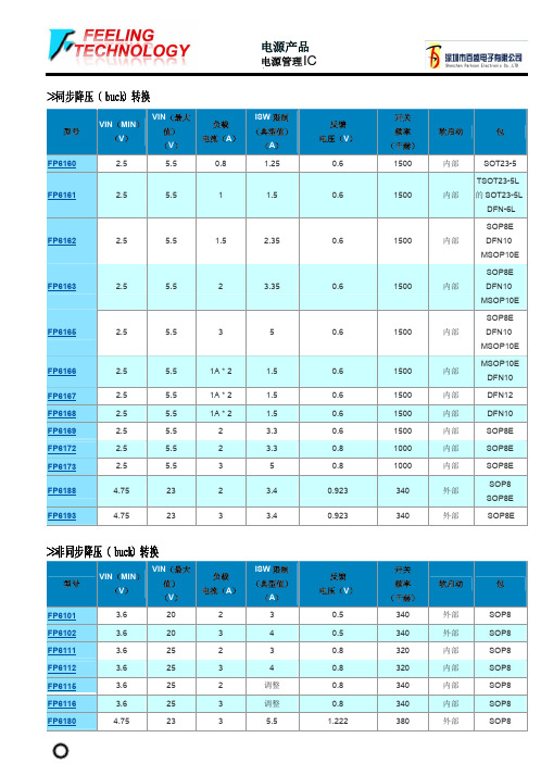
>>白光LED驱动器
型号
VIN(MIN) (V)
VIN(最大 值) (V)
VOUT (MAX)
(V)
#发光二 极管
(最大)
驱动 电流 (A)
LED 开路 普罗特。
FP7101A
4.75
23
16
4
2
FP7102
3.6
28
25
6
2
FP7103
3.6
28
25
6
3
FP7151
7
26
26
7
0.7
●
FP7152
3
25
FP103
2.5
32
FP115
3
20
IOUT (毫安)
20 20 20 100 10
参考 电压(V)
1.25 1.25 1.25 2.5 1.25
>>线性锂离子电池充电器
型号
VIN(MIN) (V)
VIN(最大 值) (V)
充电 电流(A)
涓流 充电
FP8102
4.25
5.5
1
是的
FP8103
●
FP5453
3.6
30
调整
调整
外部
●
FP5462
3.6
40
调整
调整
外部
●
●
SOP8
SOP16 ●
SSOP16
SOP16 ●
SSOP16
SOP16 ●
SSOP16
SOP16 ●
SSOP16
>>非同步升压(升压)转换器
型号
VIN(MIN) (V)
VIN(最大 值) (V)
单片机资料百度盘
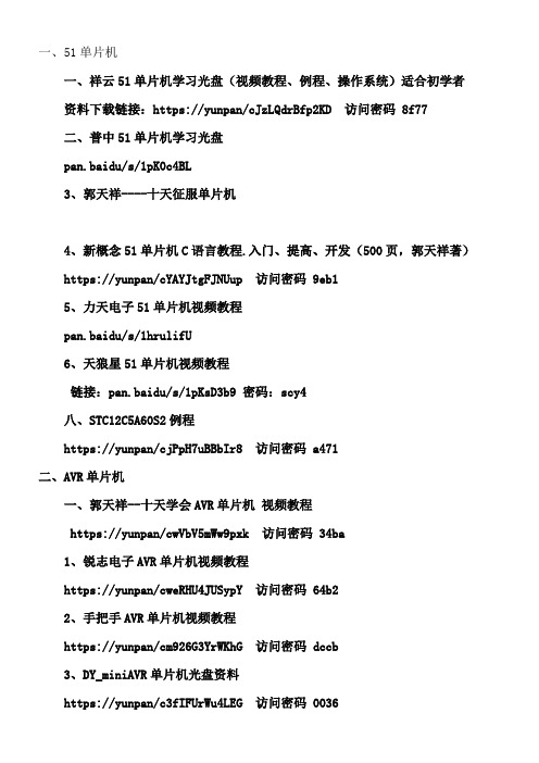
一、51单片机一、祥云51单片机学习光盘(视频教程、例程、操作系统)适合初学者资料下载链接:https://yunpan/cJzLQdrBfp2KD 访问密码 8f77二、普中51单片机学习光盘pan.baidu/s/1pK0c4BL3、郭天祥----十天征服单片机4、新概念51单片机C语言教程.入门、提高、开发(500页,郭天祥著)https://yunpan/cYAYJtgFJNUup 访问密码 9eb15、力天电子51单片机视频教程pan.baidu/s/1hrulifU6、天狼星51单片机视频教程链接:pan.baidu/s/1pKsD3b9 密码:scy4八、STC12C5A60S2例程https://yunpan/cjPpH7uBBbIr8 访问密码 a471二、AVR单片机一、郭天祥--十天学会AVR单片机视频教程https://yunpan/cwVbV5mWw9pxk 访问密码 34ba1、锐志电子AVR单片机视频教程https://yunpan/cweRHU4JUSypY 访问密码 64b22、手把手AVR单片机视频教程https://yunpan/cm926G3YrWKhG 访问密码 dccb3、DY_miniAVR单片机光盘资料https://yunpan/c3fIFUrWu4LEG 访问密码 00364、AVR代码生成器https://yunpan/c3fILqj5h3aT9 访问密码 20615、AVR开发工具https://yunpan/c3fI3satMGmSh 访问密码 d3566、AVR例程https://yunpan/c3fIFfSgCzhWE 访问密码 48c1三、msp430单片机一、郭天祥---十天学会msp430单片机https://yunpan/cYAYvyxDBaHgr 访问密码 4dca2、力天msp430单片机视频教程https://yunpan/cYAY83HwRumTn 访问密码 d66c3、msp430 c语言.pdfhttps://yunpan/cYAY577Ucc7b2 访问密码 86b34、msp430教程.pdfhttps://yunpan/cYAYtXwXYesgC 访问密码 ccbf5、IAR C 430标准库函数.pdfhttps://yunpan/cYAYnInwURHZx 访问密码 52ef 四、PIC单片机一、郭天祥--十天学会pic单片机https://yunpan/cYAYDyx2Zydsi 访问密码 af9b2、王伟民pic单片机教程https://yunpan/cYAYz37WLEaYZ 访问密码 2312五、STM32嵌入式教程一、正点原子《手把手教你学STM32-M3》-基于正点原子战舰STM32开发板2、正点原子《手把手教你学STM32-M4》-基于正点原子探讨者STM32F4开发板3、正点原子UCOS/EMWIN/LWIP视频-基于正点原子STM32开发板4、mini基础板视频教程光盘链接:pan.baidu/s/1hqVhZdq 密码:rhab5、stm32历程链接:pan.baidu/s/1jH0maay 密码:hcy26、众想单片机stm32视频教程链接:pan.baidu/s/1hrwmnRY 密码:rb887、李想stm32视频教程链接:pan.baidu/s/1jGZN9kE 密码:m9668、红龙stm32开发板光盘链接:pan.baidu/s/1i4mGYqT 密码:uc5v9、stm’32清楚教程链接:pan.baidu/s/1bogN6Gn 密码:p7pt10、stm32官方文件链接:pan.baidu/s/1c1gfzva 密码:s2gs11、stm32资料pdf资料总汇(20)篇12、基于嵌入式实时操作系统的程序设计技术_周航慈_北航.pdf13、任哲-嵌入式实时操作系统μCOS-II原理及应用.pdf14、嵌入式操作系统uCOS-II(第二版)15、ucos2经典讲解16、邵贝贝ucos操作系统全书.pdf17、零死角玩转stm32-系统篇(uCOS-II)18、ucosii学习文档集六、ARM7、ARM9视频教程一、郭天祥ARM7视频教程https://yunpan/cwVbAjCw9JL95 访问密码 627d2、郭天祥ARM9视频教程https://yunpan/cYARicupI5tjL 访问密码 1f282、郭天祥郭天祥CPLD视频教程https://yunpan/cwVbfP2dTEeRq 访问密码 f955七、CORTEX—A内核arm教程一、基于cortex-a内核的指令链接:pan.baidu/s/1c1qURXe 密码:zux42、国嵌学院cortex-a嵌入式视频全集(内部视频)链接:pan.baidu/s/1pKwEjLh 密码:mc9r3、wince6.0镜像链接:pan.baidu/s/1dEuq3uT 密码:14ww4、wince6.0源码链接:pan.baidu/s/1i4ymmdn 密码:fpb05、vs2005链接:pan.baidu/s/1boiP2Bd 密码:7spr6、QT视频教程链接:pan.baidu/s/1i4fpok1 密码:o4q3链接:pan.baidu/s/1c0ZtQbI 密码:fwkq7、QT在Android下编程教程链接:pan.baidu/s/1geft1Z1 密码:z2gq8、cortex-a下游戏安装集链接:pan.baidu/s/1o84B9WY9、天嵌210光盘资料10张(视频、源码、电路)链接:pan.baidu/s/1boCjt5110、andriod资料链接:pan.baidu/s/1i42VQSH 密码:7fbg2、windows下资料链接:pan.baidu/s/1i4bRBoT 密码:nqan3、linux操作系统资料链接:pan.baidu/s/1behIfc 密码:c13n4、wince操作系统资料pan.baidu/s/1YHVRK5、ARM64-zip链接:pan.baidu/s/1sk1Z6Mx 密码:7uc36、QT源码包链接:pan.baidu/s/1boj5ptt 密码:w9bv7、linux源码包链接:pan.baidu/s/1geyWgPd 密码:qz8z8、linux开发工具链接:pan.baidu/s/1qXaXmB6 密码:n5ka八、其他资料一、AD6.9 PCB设计教程(15G)https://yunpan/cjGM4TkItmeCH 访问密码 6e712、autocad视频教程https://yunpan/cHP5pRjnFbYEA 访问密码 ea0d3、C++课件https://yunpan/c3WZYx7h56wZW 访问密码 62f84、c语言参考手册https://yunpan/cjGMTU6WgxQs8 访问密码 65a25、protel99视频教程https://yunpan/c3FHH4rSdp8pH 访问密码 10116、protues8视频教程https://yunpan/cwVbKL73tJtkT 访问密码 068e链接:pan.baidu/s/1TYmHg 密码:5l5m7、SolidWorks视频教程(低级、高级)https://yunpan/cYABpMI5Yu4a5 访问密码 fc708、VC++视频教程https://yunpan/cYABNBtWUfziZ 访问密码 71479、zigbee文档资料视频教程https://yunpan/cYABipqm9VmTS 访问密码 737c10、zigbee-cc2530光盘资料链接:pan.baidu/s/1nubduNf 密码:h6n211、zigbee组网、栈协议教程链接:pan.baidu/s/1nubduNf 密码:h6n212、经常使用74芯片、电阻、电容、电感、三级管、运放等资料集https://yunpan/cYA6ghmYJRUMN 访问密码 5449https://yunpan/cYA6sTMXiCpEg 访问密码 86f4https://yunpan/cYA6AztRiuDHN 访问密码 8129https://yunpan/cYA6fkEyFb9qS 访问密码 bd7ahttps://yunpan/cYA6KVtPtzN8R 访问密码 751a13、VB资料文档+视频教程https://yunpan/cYA6Jt5cHvJtJ 访问密码 31a514、matlab教程文档+视频https://yunpan/cYA6Z4ZneS92Y 访问密码 bc362、瑞萨开发板光盘-电子设计大赛专用https://yunpan/cctk6idf8A7HZ 访问密码 b9253、你必需明白的495个C语言问题高清PDF中文版全书 https://yunpan/cYA6QyFqqhcqq 访问密码 ee8a4、电路设计技术与技术第二版高清楚pdf中文版https://yunpan/cYA6cfvbcMtHY 访问密码 fcaf5、战舰-GSM短信模块教程资料链接:pan.baidu/s/1qXaXmIo 密码:e2vk6、语音模块资料https://yunpan/cYA6LifVjRi2n 访问密码 0a297、无线通信模块资料https://yunpan/cYA63EabvaH6J 访问密码 9eac8、指纹识别模块资料https://yunpan/cYA6r3jtbJKYT 访问密码 e9b09、顺平linux视频教程 (内部)链接:pan.baidu/s/1nuzzQGx 密码:521t10、jave零基础视频教程链接:pan.baidu/s/1boh3v6B 密码:bqux11、大数据学习资料链接:pan.baidu/s/1kUtyzPH 密码:miv212、android电话端编程视频教程链接:pan.baidu/s/1skiwKOH 密码:rriv13、陀螺仪-飞控-四旋翼-电路仿真mulitism资料链接:pan.baidu/s/1c1mQU8S 密码:d0e6。
飞凌嵌入式AM335x产品规格书-2014-09-18

第 3页
OK335x 产品规格书 2014-09-18
第一章 产品说明
1.1 产品总述
OK335x 系列产品是由飞凌自主设计、生产和发行销售的高性能,工业级开发平台。开 发平台采用了 TI 公司的 AM335X Cortex-A8 处理器,运行主频高达 1GHz,AM335X 处理器集 成了两个千兆网卡,集成了 CAN 总线控制器,IIC 控制器,LCD 控制器,集成了 PowerVR SGX530 图形处理器,非常适合工业控制,多媒体终端等应用领域。
第四章 OK335xS-II 产品................................................................................................................20 4.1 产品概述............................................................................................................................20 4.1.1 FET335xS-II 概述................................................................................................... 20 4.1.2 OK335xS-II 概述.....................................................................................................21 4.2 产品参数............................................................................................................................22 4.2.1 FET335xS-II 硬件参数........................................................................................... 22 4.2.2 FET335xS-II 软件参数........................................................................................... 22 4.2.3 OK335xS-II 接口说明............................................................................................24 4.3 OK335xS-II 尺寸说明....................................................................................................25 4.3.1 FET335xS-II 核心板尺寸说明图........................................................................... 25 4.3.2 OK335xS-II 底板尺寸说明图.................................................................................25
STM32F102x4x6规格书PDF 最新最详细
Contents
STM32F102x4, STM32F102x6
Contents
1 2 Introduction . . . . . . . . . . . . . . . . . . . . . . . . . . . . . . . . . . . . . . . . . . . . . . . . 7 Description . . . . . . . . . . . . . . . . . . . . . . . . . . . . . . . . . . . . . . . . . . . . . . . . . 8
STM32F102x4
ST代理:
STM32F102x6
STM32F051,STM32F2,STM32F4系列,STM32F100, STM32F101,STM32F102,STM32F103,STM32F105, STM32F107,STM32L151,STM32L152,STM32F050
资料查询
深圳市恒信宇电子有限公司 1091944079@QQ.COM
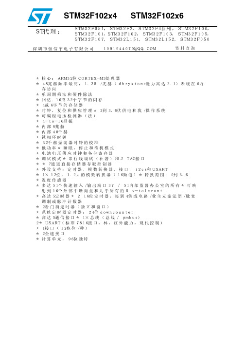
* 核心:ARM32位CORTEX-M3处理器 * 48兆赫频率最高,1.25 /兆赫(dhrystone能力高达2.1)表现在0内 存访问 * 单周期乘法和硬件除法 * 回忆:16或32个字节的闪存 * 4或6字节的存储器 * 时钟,复位和供应管理* 2到3.6伏供电和我/操作系统 * 可编程电压检测器(法) * 4-to-16晶振 * 内部8兆赫 * 内部40千赫 * 锁相环时钟 * 32千赫振荡器时钟的校准 * 低功率* 睡眠,停止和待机模式 * 电池电压供应时钟和备份寄存器 * 调试模式* 串行线调试(社署)和J TAG接口 * * 7通道直接存储器存取控制器 * 外设支持:定时器,模数转换器,接口,i2cs和USART * 1×12位,1.2μ的模数转换器(16频道)* 转换范围:0到3.6 * 温度传感器 * 多达51个快速输入/输出端口37 / 51内部监督办公室的所有* 可映 射到16个外部中断向量和几乎所有的5 v-tolerant * 高达5定时器* 2 16位定时器,每到4集成电路/业主立案法团/脉宽 调制或脉冲计数器 * 2看门狗定时器(独立和窗口) * 系统定时器定时器:24位downcounter * 高达5通信接口* 1×总线(总线/ pmbus) 2* USART(标准7816接口,林,红外能力,现代控制) * 1接口(12兆位/秒) * 2全速接口 * 计算单元,96位独特
北京聚英翱翔电子有限公司DAM1600E标准版继电器控制卡产品说明书
DAM1600E继电器控制卡说明书V1.1北京聚英翱翔电子有限公司2016年07月目录一、产品特点 (1)二、产品功能 (1)三、产品选型 (1)四、主要参数 (1)五、接口说明 (2)六、通讯接线说明 (2)1、RS232接线方式 (2)2、RS485级联接线方式 (3)七、输出接线说明 (3)1、继电器接线说明 (3)八、测试软件说明 (3)1、软件下载 (3)2、软件界面 (4)3、通讯测试 (4)九、参数配置 (5)1、设备地址 (5)2、波特率的读取与设置 (7)3、闪开闪断功能及设置 (7)十、开发资料说明 (8)1、通讯协议说明 (8)2、Modbus寄存器说明 (8)3、指令生成说明 (10)4、指令列表 (11)5、指令详解 (12)十一、常见问题与解决方法 (14)十二、技术支持联系方式 (14)一、产品特点●DC7-30V;●继电器输出触点隔离;●采用欧姆龙G2R-A-E继电器可更换;●通讯接口支持RS485、RS232;●通信波特率:2400,4800,9600,19200,38400(可以通过软件修改,默认9600);●通信协议:支持标准modbus RTU协议;●可以设置0-255个设备地址,可以通过软件设置;●具有闪开、闪断功能,可以在指令里边带参数、操作继电器开一段时间自动关闭;●具有频闪功能,可以控制器继电器周期性开关;●加入高频滤波器,提高产品的抗扰度,阻挡电网不干净电源对设备的影响。
二、产品功能●十六路继电器控制●支持电脑软件手动控制●支持顺序启动模式●支持流水循环模式●支持跑马循环模式三、产品选型型号modbus RS232RS485USB WiFi继电器DAM1600E-RS232+485●●●16四、主要参数参数说明触点容量16A/30VDC16A/250VAC耐久性10万次数据接口RS485、RS232额定电压DC7-30V电源指示1路红色LED指示(不通信时常亮,通信时闪烁)通讯指示与电源指示灯共用输出指示16路红色LED指示温度范围工业级,-40℃~85℃尺寸180*94*41mm重量330g默认通讯格式9600,n,8,1波特率2400,4800,9600,19200,38400软件支持配套配置软件、控制软件;支持各家组态软件;支持Labviewd等五、接口说明六、通讯接线说明1、RS232接线方式RS232接线为标准DB9母头接口,为直连线。
飞扬电子产品选型手册说明书

在开始使用前请仔细阅读下面说明概述飞扬电子主要是销售信号采集,控制卡的公司,主要从事的行业是测控行业。
目前已有的产品包括PCI 总线,PCIe总线,USB总线,串口等等。
保修用户需要遵守储存、运输和使用的要求。
因违反操作规定和要求而造成损坏的,需缴纳器件费和维修费及相应的运输费用,如果板卡有明显烧毁、烧糊情况原则上不予维修。
保修期:一年。
具体的维修细则请参看产品的手册附录。
版权信息保留在不另行通知的情况下,更新手册的权利。
不承担由于使用产品不当,所造成的直接、间接、附带的或相应产生的损失或责任。
本产品及其软件具有专利权、版权及其他知识产权。
未经授权,不得直接或间接复制、制造、加工本产品及其相关部分。
应用范围本产品设计制造由于普通工业应用,不能用于易燃易爆等危险场合,超于预料的用途或对人的生命或财产造成重大影响的场合不在本产品应用和服务的范围内。
软件支持服务终身提供技术支持。
目录在开始使用前请仔细阅读下面说明 (1)一、概述 (3)1.1 产品信息 (3)1.2 使用流程 (4)1.3 选型建议 (4)1.4 产品优势 (6)二、主要产品展示 (7)FY2400 (7)FY2450 (8)FY4400 (9)FY4401 (10)FY4405 (11)FY6400 (12)FY6402 (13)FY6403 (14)FY6405 (15)FY6451 (16)FY5400 (17)FY5402 (18)FY5403 (19)FY5405 (20)FY5451 (21)FY3400 (22)FY3401 (23)FY3402 (24)FY3403 (25)FY3404 (26)FY3405 (27)FY3406 (28)FY3451 (29)三、用户注意事项 (30)四、版本信息 (31)一、概述1.1 产品信息简介本公司的IO (开关量/数字量)控制板卡,是实现自动化控制的基础设备。
产品按照总线可以分为:PCI总线;PCIe 总线;USB 总线;RS232总线控制卡是在工业控制领域,自动化集成设备中应用的一种电子设备。
单片机说明书
•
San Jose, CA 95134-1709 • 408-943-2600 Revised September 27, 2005
CY7C68013A/CY7C68014A CY7C68015A/CY7C68016A
1.1 Features (CY7C68013A/14A only)
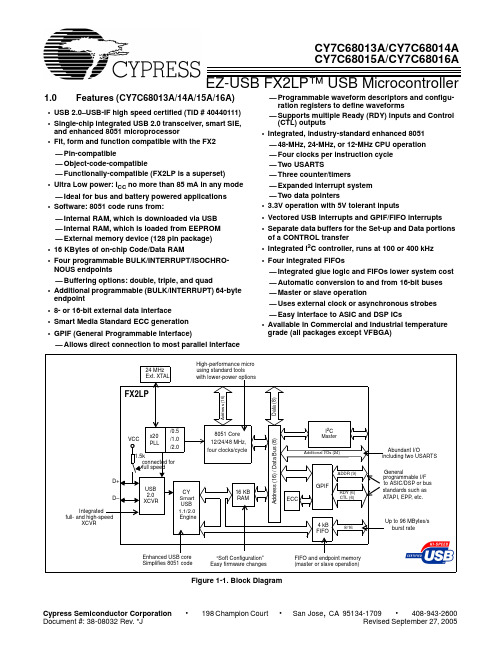
USB 2.0 SIE or external transceiver implementations. With EZ-USB FX2LP, the Cypress Smart SIE handles most of the USB 1.1 and 2.0 protocol in hardware, freeing the embedded microcontroller for application-specific functions and decreasing development time to ensure USB compatibility. The General Programmable Interface (GPIF) and Master/Slave Endpoint FIFO (8- or 16-bit data bus) provides an easy and glueless interface to popular interfaces such as ATA, UTOPIA, EPP, PCMCIA, and most DSP/processors. The FX2LP draws considerably less current than the FX2 (CY7C68013), has double the on-chip code/data RAM and is fit, form and function compatible with the 56-, 100-, and 128pin FX2. Five packages are defined for the family: 56VFBGA, 56 SSOP, 56 QFN, 100 TQFP, and 128 TQFP.
保定飞凌嵌入式技术 OK2440开发板 说明书 V2.0
OK2440用户手册V2.0保定飞凌嵌入式技术有限公司网站:论坛:/bbsOK2440是由飞凌嵌入式技术有限公司设计生产的一款基于ARM9的嵌入式开发平台,它基于三星公司的ARM处理器S3C2440A,内部带有全性能的MMU(内存处理单元),适用于设计移动手持设备类产品。
OK2440开发板采用核心板+底板设计,性能稳定可靠,具有高性能、低功耗、接口丰富和体积小等优良特性。
目前已成功移植Linux,WINCE等操作系统到OK2440-II开发板。
在使用开发板时,请注意以下事项:1.用户在拿到开发板后,请至网站“客户服务”页面注册,并用电话(0312-*******)通知我们您的姓名,购买时间,注册名称,开发板的编号,我们会及时为您开通会员权限,便于您及时下载更新的资料!2.第一次使用OK2440开发板时,请务必先阅读用户手册,按照手册上所述进行相关操作,谨防随意破坏系统程序!3.每次使用OK2440开发板前,请先将手接触开发板周围金属接口或者其它地方放电,避免直接用手触摸芯片造成芯片烧坏!4.需要对开发板进行物理操作时,请关闭电源,除USB以及网络接口(如果与局域网相接请使用普通网线,开发板带网线为计算机直连网线)外,其它接口均不支持热插拔,开发板工作时,请不要带电插拔。
5.本开发板硬件保修时间为三个月(非人为或不可抗力原因除外),技术支持时间一年(论坛技术支持及“客户服务”下载时间不在此限),方式为BBS和电话支持。
最后,欢迎您使用OK2440开发板,并提出宝贵意见!编者:飞凌嵌入式技术有限公司地址:河北保定市七一西路165号邮编:071051电话:0312-*******传真:0312-*******E-mail:bdht@网址:论坛:/bbs目录一.第一章OK2440开发板硬件介绍 (5)1.1开发套件包含的内容 (5)1.2用户光盘内容说明 (5)1.3OK2440开发板外观 (6)1.4OK2440开发板硬件资源 (6)1.5硬件资源分配 (8)1.5.1地址空间分配以及片选信号定义 (8)1.5.2开发板接口说明 (9)1.5.3按键说明 (9)1.5.4LED指示灯说明 (10)1.5.5跳线分配表 (10)1.6OK2440开发板主要硬件说明 (10)1.6.1系统存储器 (10)1.6.2JTAG及复位逻辑 (12)1.6.3LCD/触摸屏接口引脚定义 (14)1.6.4IDE(也作为总线接口)接口引脚定义 (16)1.6.5GPIO扩展口引脚定义 (17)1.6.6SD卡接口 (18)1.6.7IIS音频输入输出接口 (19)1.6.8摄像头接口: (20)1.6.9串口电路 (20)1.6.10USB接口 (22)1.6.11功能按键及用户LED指示灯 (22)1.6.12AD转换电路 (24)1.6.13红外接收电路 (25)1.6.14温度传感器 (26)1.6.15IIC电路(24c02) (26)1.7OK2440支持的操作系统及其驱动 (27)1.7.1Linux操作系统 (27)1.7.2WINCE操作系统 (27)二.第二章OK2440开发板基本使用 (29)2.1OK2440外部硬件连接 (29)2.2WINDOWS下驱动的安装 (29)2.2.1安装USB驱动 (29)2.2.2安装并口驱动程序 (31)2.3调试终端使用 (34)2.3.1DWN软件的使用 (34)2.3.2超级终端的使用 (35)2.4BOOTLOADER使用全攻略 (39)2.4.1bootloader简介 (39)2.4.2功能菜单说明 (39)2.4.3选择菜单说明 (41)2.4.4参数设置说明 (41)2.4.5通过USB下载程序并写入FLASH (43)2.4.6用sjf2440.exe烧写bootloader程序 (45)2.5ADS下的LED试验 (46)2.5.1ADS安装 (46)2.5.2使用ADS创建工程 (46)2.5.3编译和链接工程 (52)2.5.4H-JTAG的安装使用 (59)2.5.5用AXD进行代码调试 (61)一.第一章OK2440开发板硬件介绍OK2440开发板采用核心板+底板的模式,核心板为6层,底板为2层。
CA51F5 系列 MCU 中文用户手册说明书

Built - in 16 Bit PWM / Touch Key / 1T 8051 8K Flash MCUCA51F5系列MCU中文用户手册REV 2.2深圳市锦锐科技股份有限公司电话:*************传真:*************地址:中国广东省深圳市南山区沙河西路深圳湾科技生态园一区2栋B座5层目录1 概述 (5)2 基本特性 (5)3 芯片型号功能介绍 (7)4 系统框图 (8)5 引脚封装及其描述 (9)5.1封装定义 (9)5.2引脚描述 (11)6 中央处理器(CPU) (13)6.1CPU简介 (13)6.2寄存器描述 (13)7 存储器系统 (17)7.1 随机数据存储器(RAM) (17)7.2 特殊功能寄存器(SFR) (17)7.3 Flash存储器 (18)7.3.1 功能简介 (18)7.3.2 Flash存储器组织结构 (18)7.3.3 Flash寄存器描述 (19)7.3.4 Flash控制例程 (22)7.4外部RAM映射为程序空间 (24)8 中断系统 (25)8.1 功能简介 (25)8.2 中断逻辑 (25)8.3 中断向量表 (26)8.4 中断控制寄存器 (26)8.5 外部中断 (28)8.5.1外部中断介绍 (28)8.5.2外部中断寄存器 (28)8.5.3外部中断控制例程 (30)9 时钟系统 (32)9.1 时钟系统介绍 (32)9.1.1 时钟专用名称定义 (32)9.1.2 内置16MHz RC振荡器(IRCH) (32)9.1.3内置131 KHz RC振荡器(IRCL) (32)9.2 时钟控制寄存器描述 (33)9.3 系统时钟 (35)9.3.1 系统时钟结构图 (35)9.3.2 系统时钟控制寄存器描述 (35)9.3.3 系统时钟控制方法及例程 (36)10 供电和复位系统 (37)10.1 供电系统 (37)10.1.1 LDO功能简介 (37)10.1.2 LDO控制寄存器 (38)11 功耗管理 (42)11.1 IDLE模式 (42)11.2 STOP模式 (42)11.3 低速运行模式 (43)11.4 低功耗相关寄存器描述 (43)11.5 低功耗模式控制例程 (44)12 通用定时器(定时器0,定时器1,定时器2) (47)12.1 定时器0 (47)12.1.1 定时器0介绍 (47)12.1.2 定时器0寄存器描述 (48)12.2 定时器1 (50)12.2.1 定时器1介绍 (50)12.2.2 定时器1寄存器描述 (51)12.3 定时器2 (52)12.3.1 功能简介 (52)12.3.2 定时器2寄存器描述 (53)13 看门狗定时器(WDT) (56)13.1 看门狗定时器(WDT)功能简介 (56)13.2 看门狗定时器(WDT)寄存器描述 (56)13.3 看门狗定时器控制例程 (58)14 TMC定时器 (60)14.1 TMC功能简介 (60)14.2 TMC寄存器描述 (60)14.3 TMC控制例程 (61)15 通用输入输出口(GPIO)及复用定义 (62)15.1 功能简介 (62)15.2 引脚寄存器描述 (64)15.3 引脚控制例程 (69)16 通用串行接口(UART0) (70)16.1 功能简介 (70)16.2寄存器描述 (74)17 I²C接口 (76)17.1 功能简介 (76)17.2 I2C主要特点 (76)17.3 I2C功能描述 (76)17.4 I2C通信引脚的映射 (78)17.5 寄存器描述 (78)17.6 I2C控制例程 (81)18 PWM (88)18.1 PWM功能简介 (88)18.2 PWM功能描述 (88)18.3 PWM寄存器描述 (90)18.4 PWM功能控制例程 (99)19 数模转换器(DAK) (102)19.2寄存器描述 (102)19.4 DAK控制例程 (103)20电容式触摸按键(Touch Key) (104)20.1 功能简介 (104)20.2 主要特性 (104)20.3 结构图 (105)20.4 功能描述 (105)20.4.2 手动模式和自动模式 (105)20.4.3 触摸时钟预分频 (105)20.4.4 低功耗模式 (106)20.4.5触摸按键共用LED驱动 (106)20.5 寄存器描述 (107)20.6 触摸控制例程 (120)21低电压检测(LVD) (121)21.1 功能简介 (121)21.2 功能描述 (121)21.3 寄存器描述 (122)21.4 LVD控制例程 (123)22程序下载和仿真 (125)22.1 程序下载 (125)22.2 在线仿真 (125)23电气特性 (126)23.1 极限参数 (126)23.2 直流电气特性 (126)23.3交流电气特性 (128)24封装类型 (129)25附录 (133)附录1 指令集速查表 (133)1 概述CA51F551系列芯片是基于1T 8051内核的8位微控制器,通常情况下,运行速度比传统的8051芯片快10倍,性能更加优越。
C8051F MCU选型指南

Engineering for a mixed-signal world.SPRING 2013Engineering for a mixed-signal world.Mixed-Signal 8-bit and 32-bit Microcontrollers /MCUSPRING 2013MICROCONTROLLERPRODUCT SELECTOR GUIDE2 / M I C R O C O N T R O L L E R S E L EC T O R G U I D EProduct Selector Tables32-bit Microcontroller ProductsREQUEST SAMPLES AND DOWNLOAD DOCUMENTATION AT /32bit-mcu™™™M I C R O C O N T R O L L E R S E L EC T O R G U I D E /3®®REQUEST SAMPLES AND DOWNLOAD DOCUMENTATION AT /mcu4 / M I C R O C O N T R O L L E R S E L EC T O R G U I D EM I C R O C O N T R O L L E R S E L EC T O R G U I D E / 56 / M I C R O C O N T R O L L E R S E L EC T O R G U I D EM I C R O C O N T R O L L E R S E L EC T O R G U I D E / 78 / M I C R O C O N T R O L L E R S E L EC T O R G U I D EM I C R O C O N T R O L L E R S E L EC T O R G U I D E / 910 / M I C R O C O N T R O L L E R S E L E C T O R G U I D ELow-Power MCUsM I C R O C O N T R O L L E R S E L EC T O R G U I D E / 1112 / M I C R O C O N T R O L L E R S E L E C T O R G U I D EM I C R O C O N T R O L L E R S E L EC T O R G U I D E / 1314 / M I C R O C O N T R O L L E R S E L E C T O R G U I D EM I C R O C O N T R O L L E R S E L EC T O R G U I D E /15Precision32 AppBuilder Rapid Prototyping UtilitySilicon Labs’ Precision32 AppBuilder graphical rapid prototyping and code generation utility helps designers get up and runningquickly. Designers can easily set-up and adjust pin configuration, map peripherals, configure clocking trees and generate source code allwithout wading through programming register bits in the data sheet. A sophisticated error checking engine validates peripheral properties and pin assignments, and provides real-time feedback when conflicts are detected.Last minute changes… No problem. New peripherals can be easilyadded with simple firmware modifications so developers won’t have to work weekends to try to accommodate new features.Precision32 Integrated Development EnvironmentSilicon Labs’ Eclipse-based IDE includes a full compiler, debugger and an online dashboard for application-critical information such as a software libraries with example code, data sheets, schematics, PCB footprints, application notes, active version tracking andautomatic updates. These tools are available for free, without code size or time restrictions.Precision32™ 32-bit Microcontroller SoftwareFIND THE TOOLS YOU NEED TO HELP WITH YOUR ENTIRE PROJECT /32bit-softwareSilicon Labs 8-bit IDEThe Silicon Labs Integrated Development Environment (IDE) is a complete, stand-alone software program that includes the items following:The IDE interfaces to third party development tool chains to provide system designers a complete embedded software development environment. The IDE and other development tools run under the Windows 2000, Windows XP and Windows Server 2003 operating systems and support the entire MCU portfolio.• 4 kB C compiler included • Source code editor • Project manager• Keil 8051 macro assembler and linker • Device programmer• Supports full-speed, non-intrusive, in-circuit debug logic • Source-level debug• Variable watch window • Real-time breakpoints• Conditional memory watchpoints • Memory and register inspect/modify • Supports third-party development tools • Single-step and animated execution modes8-bit Microcontroller SoftwareFIND THE TOOLS YOU NEED TO HELP WITH YOUR ENTIRE PROJECT /8bit-software16 / M I C R O C O N T R O L L E R S E L E C T O R G U I D EHardware SupportFIND THE TOOLS YOU NEED TO HELP WITH YOUR ENTIRE PROJECT /MCU Development KitsSilicon Labs offers complete tools to help designersthroughout the entire project. All microcontroller solutions offerhardware and software platforms to easily set up and configure,compile and debug a project. Full documentation and a broadrange of third-party compilers and development tools areavailable. Software stacks provide networking support formulti-node metering networks. Software simulation tools canestimate power consumption and determine expected batterylife. /devkitsComplete development/prototyping system includes the following:• Prototyping/demonstration board• Integrated development environment• Configuration tools• MCU configuration wizardSiM3U1xx Precision32 32-bit MCU UDP CARD C8051F996 LOW POWER TARGET BOARDMCU USB TOOLSTICK C8051F990 SLIDER EVALUATION KITM I C R O C O N T R O L L E R S E L EC T O R G U I D E / 17CLASS D TOOLSTICKBATTERY LIFE ESTIMATION UTILITY C8051F960 MCU UDP CARD WITH Si1120 DAUGHTER CARD Unified Development PlatformSilicon Labs offers an innovative approach in hardware support with the Unified Development Platform (UDP), featuring a main mother board, modular daughter cards, integrated LCD and ample real estate for prototyping, expansion and integration. The UDP provides a standalone demonstration and software development platform for the Wireless MCU devices and both 8-bit and Precision32™ 32-bit MCU products. Kits include UDP base boards and RF test cards. Additional test cards may be ordered if the 915 MHz or 868 MHz test cards don’t satisfy the requirements for the end application. /UDPThe UDP platform supports all of the following:• MCU code and firmware development (IDE, Configuration Wizard, example code etc.)• RF design and optimization (WDS support, automatic board detection and firmware download, sample RF code, run-time PHY interface etc.)• Networks and protocol stacks (such as the wireless M-Bus stack)Test CardsPico CardI/O CardUDP MotherboardMCU Card18 / M I C R O C O N T R O L L E R S E L E C T O R G U I DEThird Party Tool SupportA broad range of third-party compilers and development tools are available including a free Small Device C Compiler (SDCC) supported by Application Note 198, “Integrating SDCC 8051 Tools into the Silicon Labs IDE.” Device programming and source-level debug of OMF-51 object files is fully supported.Product and Design SupportThe MCU Knowledge Base provides answers to common technical questions about the MCU product line and product use. MCU User’s Forum is a place where C8051 MCU users can share experiences and technical questions with other users. For MCU support email: mcuapps@Microcontroller ResourcesFIND THE TOOLS YOU NEED TO HELP WITH YOUR ENTIRE PROJECT/mcuCross-Reference UtilitySilicon Labs’ cross reference utility allows you to type in acompetitor’s part number (full or partial) and if we have a cross-match, our part number pops up. Results are automatically filtered as you type and can be exported to excel so you can e-mail or save results. /cross-referenceSilicon Labs Online UtilitiesFIND THE TOOLS YOU NEED TO HELP WITH YOUR ENTIRE PROJECT/online-utilitiesBattery Life EstimatorThe Battery Life Estimator is an easy-to-use web-based calculator that gives designers a quick and easy way to understand the discharge characteristics of different system configurations to help optimize low-power applications. You can also download the software to your desktop. /batterycalculatorMCU Parametric SearchSilicon Labs offers an easy-to-use parametric search for ourMicrocontroller products. Click the buttons to filter as you search for the features you require and find the perfect part to meet your needs. You can then buy or sample parts or export your results into a sortable Excel spreadsheet. /parametric-searchParametric Search iPad AppTake the parametric search mobile! The Silicon Labs Parametric Search iPad app makes it easy to find exactly what you need for your next embedded design. Quickly jump between microcontroller and other product families. Access data sheets and other documentation directly in the app and download to iBooks for offline access. Browse detailed product information – features, applications, block diagrams and even order samples and development kits, all from within the app. Offline access available – refresh data the next time you’re connected to the Internet./parametric-searchISO 9001ISO 14001ISO/TS 16949SILICON L ABOR ATORIE S INC. | 400 W. CE SAR CHAVEZ | AUSTIN, T X 78701 | USA | +1 (512) 416-8500 | SIL 。
MCU002 远程控制单元说明书
Model: MCU002 Remote Control UnitIndex1. Model: MCU0022. Specifications2-1. Standard Comprising2-2. Technical Specifications3. Operations – User Interface3-1. Getting Started – Model TZT9/14/BB New Version v3.123-2. Keys and Functions – Basic Operations3-3. Showing a Cross Cursor – New with Model TZT9/14/BB v3.123-4. Auto Scroll ON or OFF – New with Model TZT9/14/BB v3.123-5. Entering a Point – New with Model TZTBB and TZT14 (External Touch Screen Mode) v3.123-6. User Interface Auto-Hide “10 Seconds” Recommended3-7. Limitations and Notes4. Installing Model MCU0024-1. Dimensions4-2. Flush Mounting4-3. Interconnection5. Model MCU002 with TZT9/14/BB v3.02 or Earlier6. Tips – Model TZT9/14/BB with Generic HID Mouse1. Model: MCU002The Model MCU002 is a compact remote control unit for use with the TZT9/14/BB. It offers the expandability of multi touch operation of the TZT9/14/BB to the hardware key operation, as the best supplemental tool to multi touch operation. This document describes the basic information on specifications, operations, and installation of the MCU002.Model: MCU002Screen Image from TZTBB2. Specifications2-1. Standard ComprisingThe MCU002 (00002546100) comes with the components shown at right.(Components) (Carton)2-2. Technical SpecificationsInterface USB2.0 Cable Length 2 mPower Supply via USB port Water ProofFront: IP56 Rear: IP22 Operating Temperature -15 to +55℃Humidity 40℃ 94% or less (without internal fogging) MountingFlush mount from the front side (See Section 4-2)NameTypeQtyL (175 mm)W (85 mm)H (100 mm)Remote control unit MCU002 1 Front panelFRC-D01-0031 Flush mount gasket FRC-D01-008 1 Flush mount screwBH3*13 TAB-B4 User’s Guide (English)13. Operations – User Interface3-1. Getting Started – Model TZT9/14/BB New Version v3.12To fully make use of the MCU002, update the TZT9/14/BB to v3.12, which will be released in May 2014.3-2. Keys and Functions – Basic OperationsThe MCU002 consists of 10 hardware keys to control the TZT9/14/BB as described below.MCU002NoKeysDescriptions(1) STBY / AUTO Sets the NAVpilot-700 to STBY or AUTO modes (2) CENTER Sets the ship in the center of the screen(3) CURS / SCRL Switches the joystick functions between Cursor and Scroll (4) Joystick Moves a cursor in 8 directions (5) - / ▲ (UP)Acts as rotating RotoKey™ clockwise(6) + / ▼ (DOWN) Acts as rotating RotoKey™ counterclockwise(7) ENT Acts as pushing RotoKey™ (8) CANCEL & MOBShort presss to cancelLong press to enter an MOB point (9) FUNC Acts as Function Gesture(10) HOME & BRILLShort press to access the Home page Long press to open the Brilliance control box(1) STBY / AUTOThis key activates the NAVpilot-700 AUTO and STBY modes . When opening the NAVpilot-700 control window on the TZT9/14/BB, you can activate the AUTO mode from the MCU002 [STBY/AUTO ] key.When the NAVpilot-700 mode is changed between AUTO/NAV and STBY with the MCU002 or touch operations, the TZT9/14/BB will generate abeep sound with the following notification on the top of the screen.STBY to AUTO/NAVAUTO/NAV to STBYThe notification of [NAVpilot is engaged.] will appear . The notification of [NAVpilot is disengaged.] will appear .(2) CENTERThis key sets the own vessel to the center on the screen of Plotter and Radar and cancels echo history of Fish Finder .(3) CURS / SCRL (CURSOR / SCROLL)This key switches the joystick functions between cursor and scroll modes . At default the joystick works to move a cursor . Pressing the [CURS/SCRL ] key, the joystick works to scroll the Chart, Radar , and Fish Finder screen. Plotter screen – Cursor in motionPlotter screen – Scrolled with joystick(4) JoystickThe joystick can move in eight (8) directions to move a cursor or scroll the screen as shownabove. It also has a “push” function. As an example, if you push the joystick on the Plotter screen,contextual menus will appear as follows.(Sample: Plotter screen from TZTBB)Note:The joystick has NO “drag” function. For details on limitationsof operations with the MCU002, see Section 3-5.(5)- / UP (▲)(6) +/ DOWN (▼)(7) ENTThese three (3) components work as the RotoKey™: [-/▲ (UP)] key as rotating the RotoKey™clockwise, [+/▼(DOWN)] key as rotating the RotoKey™ counterclockwise, and [ENT] as pushing theRotoKey™. The following screenshots from the Plotter page show how to operate these keys.Press [ENT] to show RotoKey™ menus.Press [-/▲] or [+/▼] to move the RotoKey™ menus andpress [ENT]. In this example, [Overlay] is selected.] to zoom in or zoom out the Plotter and Radar screen.(8) CANCEL & MOBThis key has two (2) functions: Short press to activate the “CANCEL ” and long press the “MOB ” functions as shown below. Short Press for “CANCEL”Long Press for “MOB”- Closes Home/Menu/Lists/Tides/Catalog pages, RotoKey™ and contexual menus, and dialog boxes - Mutes alarm sound- Ends action such as creating a route and moving a point Note : No “Undo” function - Enters an MOB point at the own ship’s position(9) FUNC (FUNCTION)This key activates the function set in [Menu] – [General] – [Function Gesture]. In the following example, the Function Gesture is assigned to [Event]. The [FUNC ] key pops up the event window. Youcan select an event mark with the [-/▲] or [+/▼] key and enter it with the [ENT ] key, or place a cursor with the joystick on a required event mark and push the joystick.(10) HOME & BRILLThis key has two (2) functions: Short press to activate the “HOME ” and long press the “BRILL ” functions. On the Home page and Brilliance window, you can proceed to further settings as follows.Short Press for “HOME” Long Press for “BRILL”Press [-/▲] or [+/▼] to select a page and [ENT ] to open the selected page.Press [-/▲] or [+/▼] to adjust the brillaince and[CANCEL ] to close the window. To turn off the unit, place a cursor with the joystick on [Power Off This Device] or [Power Off Network] and press it.Note:It is not possible to turn on the TZT9/14/BB with the MCU002 although the power can be turned off as shown above.3-3. Showing a Cross Cursor – New with Model TZT9/14/BB v3.12The TZT9/14/BB v3.12 program has new setting options of Cross Cursor and Cross Cursor Speed , which enables to show a cross cursor on the screen and adjust its speed. With the MCU002, the cross cursor will help to see a present cursor location.While the joystick in operation, the gray, thick cross cursor appears on the screen.The cursor speed can be adjusted between [1] and [20]: [1] – slowest, [8] – default, and [20] – fastest.Cross Cursors on Other ScreensTips – No cross cursor while touch operationsWhen the TZT9/14/BB is operated by touch, the cross cursor will not appear. The cross cursor will appear only when the cursor is in operation with the MCU002 joystick.3-4. Auto Scroll ON or OFF – New with Model TZT9/14/BB v3.12The TZT9/14/BB v3.12 program has another new setting option of Auto Scroll, which enables to scroll the Plotter, Radar, and Sounder screen by placing a cursor at the edge of the screen. The following screenshots show the menu settings and scroll motions.At default, the Auto Scroll mode is set to OFF. When a cursor In this example, a cursor is placed at the left edge of thePlotter screen, while the chart is automatically scrolled.(You can see the [Center Vessel] icon.) To stop the scrollmotion, place the cursor away from the edge.3-5. Entering a Point– New with Model TZTBB and TZT14 (External Touch Screen Mode) v3.12Pushing the MCU002 joystick, [New Point] will be highlighted at default on the contextual menus. You can just press [ENT] to enter the point.Note:This specification is for the TZTBB and TZT14 under the External Touch Screen Mode only. With the TZT9 and TZT14without the External Touch Screen Mode, the top one or previously-selected one of the contextual menus will be highlighted even if the joystick is pushed.See each screenshot below.With the TZT9 and TZT14 without the3-6. User Interface Auto-Hide “10 Seconds” RecommendedIn [Menu] – [General], there is a setting option of [User Interface Auto-Hide]. This setting offers the time period before the popped-up RotoKey™ or contextual menus and window closes. With the MCU002 in use, the setting of “10 seconds” is useful to show the popped up items for a longer time.Contextual menus will stay for 10 seconds3-7. Limitations and Notes(1) Limitation in Drag by JoystickThe joystick has NO “drag” function . The guard zone setting of Radar , which requires to be adjusted by drag, will not be available with the MCU002 joystick. This operation should be made by touch operations or with a generic mouse/trackball unit.(2) Limitation in 3D Mode – Pan/TiltYou can turn the screen mode into the 3D mode by selecting [3D Mode] from the contextual menu. However , you cannot pan/tilt the chart with the MCU002 because sliding the screen with two fingers is the only way to pan/tilt it. The chart in 3D is always in the default angle as shown at right. Or if you have paned/tilted the chart with two fingers before, the screen will be in the previously-set angle.(3) Note on Cross Cursor PositionThe cross cursor position will not appear on the data box. Toshow the cursor position, ensure to push the joystick and show pop-up windows like you tap the screen.2nd Layer1st Layer“UP” arrow“DOWN” arrow(5) Note on Virtual KeyboardTo enter characters and numbers with a virtual keyboard, use the joystick: Place a cursor on a required key and push the joystick.(6) Note on Active WindowIn the split screen mode, even if you place a cursor on a different screen, the window will not be active. Ensure to press any key such as joystick on the screen like you tap the screen to activate it.(7) Note on Power On/OffIt is not possible to turn on the TZT9/14/BB with the MCU002. Ensure to press the Power key of the TZT9/14/BB. However, the power can be turned off with the operation of [HOME & BRILL] key and joystick as described in Section 3-1 (10) HOME & BRILL and shown at right4. Installing Model MCU002 4-1. Dimensions4-2. Flush MountingThe MCU002 can be flush mounted on a console from the front side as shown in the illustration at right.4-3. InterconnectionThe MCU002 can be used with the TZT9, TZT14, and TZTBB by USB connection. Connect the MCU002 to the USB port of the TZT9/14/BB as shown in the following examples.TZTBB with MCU002 TZT14 with MCU002TZT9 with MCU002Notes:(1) A maximum of two (2) sets of MCU002 can be connected toone (1) USB port via a USB hub as shown at right.(2) When there are two (2) sets of MCU002 are connected to one(1) TZT9/14/BB, we recommend that both MCU002 unitsshould not be operated simultaneously because it can give aload on the system.(Extracted from User Guide)5. Model MCU002 with TZT9/14/BB v3.02 or EarlierIf the MCU002 is used with the TZT9/14/BB v3.02 or earlier program, there will be limitations as described below.(1) No gray, thick cross cursor is available because there is no menu option of Cross Cursor . (2) Only the joystick will work. Other hardware keys will not work because the v3.02 or earlier programs do not detect these key codes from the MCU002. The [-/▲] and [+/▼] keysmay react but will just scroll the screen upwards and downwards respectively.6. Tips – Model TZT9/14/BB with Generic HID MouseWhile the TZT9/14/BB is preloaded with an HID driver , a generic HID mouse (USB mouse) or trackball unit with a wheel can also be used . If the Cross Cursor mode is activated on the TZT9/14/BB v3.12 [Menu] – [General] – [Cross Cursor], it will be more useful to follow thecursor motion.Each mouse/trackball component will work as follows.(Sample shot: LTSX50 (2) Push to show RotoKey ™ items in gold at the right sideRight-click to activate the preset function in [Menu] – [General] – [Function with left-click--- END ---3HistoryRelease Date Page Section Descriptions1st release Apr . 16, 2014 - - -Rev. 1 May xx, 2014 10 3-4 Descriptions of the Auto Scroll mode are added.Rev. 1 May xx, 2014 10 3-5 Section numbers are changed after adding the descriptions of the Auto Scroll mode in Section 3-4.Rev. 1 May xx, 2014 11 3-6 Rev. 1 May xx, 2014123-7。
