USB彩屏版测试仪使用说明
USB彩屏测试仪UM34C使用说明书
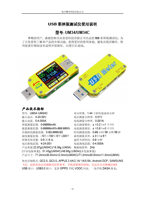
USB彩屏版测试仪使用说明型号:UM34/UM34C尊敬的用户,感谢您购买由睿登科技有限公司出品的USB彩屏版测试仪,为了让您更快了解本产品的全部功能,获得更好的使用体验,避免出现误操作,使用前请仔细阅读本说明并保留好,以便日后查阅。
产品技术指标型号:UM34 /UM34C显示屏幕:1.44寸彩色液晶显示屏输入电压:4-24.00V电压测量分辨率:0.01V输入电流:0-4.000A电流测量分辨率:0.001A容量测量范围:0-99999mAh电压测量精度:±(0.2%+1个字)能量测量范围:0-99999mWh-999.99Wh 电流测量精度:±(0.8%+3个字)负载阻抗测量范围:0.8Ω-9999.9Ω 时间测量范围:0-99小时59分钟59秒温度测量范围:-10℃~100℃/0℉~200℉温度测量误差:± 3℃/ ± 6℉屏幕亮度设置:0-5共6级延时关屏时间:0-9分钟电压曲线范围:4-24.00V 电流曲线范围:0-4.000A产品重量:22.87g(UM34C)/18.39g (UM34)数据刷新率:2Hz(不含包装重量);51.43g(UM34C)/46.95g (UM34)(含包装重量)产品尺寸:71.2mmx30.5mmx12.4mm(UM34C)/71.2mmx30.5mmx11.3mm(UM34)快充识别模式:QC2.0、QC3.0、APPLE 2.4A/2.1A/ 1A/0.5A、Android DCP、SAMSUNG (注:此快充协议识别模式仅供参考,手机更新换代较快,无法百分百准确识别)USB接口:USB3.0接口,支持OPPO手机VOOC闪充,一加手机DASH快充。
功能界面测量主界面快充识别界面充电记录界面线阻测量界面测量曲线界面系统参数设置界面核心功能USB3.0接口快充模式识别手机APP 控制自带中英文帮助界面数据记录、存储及导出容量/能量检测压差法测量线阻阻值负载接入检测功能,测试仪自动熄屏后,插上负载,自动点亮屏幕输入电压电流及功率检测屏幕可四向旋转面板说明A:Micro USB接口B:多功能按键(共4个)C:蓝牙电源开关D:USB 3.0母座接口E:USB 3.0公头接口F:Type-C 输入接口(仅做USB转Type-C线内阻测量用)G:1.44寸彩色液晶显示屏H:蓝牙指示灯:当连接上位机软件后,蓝牙指示灯由闪烁变为长亮;联机后,屏幕显示蓝牙标志。
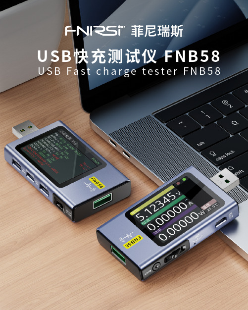
FNB58 USB快充测试仪 使用说明书
USB快充测试仪 FNB58目 录五、 外观结构03六、 技术指标044.0.2 快充触发类034.0.3 线材鉴别类024.0.4 杂类037.0.2 监测页面057.0.3 波形页面067.0.4 应用页面06058.0.1 自动检测078.0.2 PD触发器078.0.3 小米PD触发器088.0.5 QC3.0触发088.0.4 QC2.0触发088.0.6 FCP触发098.0.7 SCP触发098.0.8 AFC触发098.0.9 VOOC/WARP触发098.0.10 SVOOC 1.0/SVOOC 2.0触发0910.0.2PD监听器1210.0.3PD转换器1310.0.4USB-C电子标签13十、工具箱119.0.2电池容量计算109.0.3离线记录10九、能量统计0911.0.2记录1611.0.3触发1711.0.4系统1711.0.5关于1710.0.7模拟APPLE 2.4A15141410.0.5读取DASH线缆10.0.6模拟DASH一、版本与更新由于仪表功能极多且软硬件更新频繁,说明书随时可能更新,请知悉。
请在官网上获取最新的更新信息。
二、概述FNB58 USB测试仪是一款高可靠性、高安全性的USB电压电流检测表及移动通信终端快充触发仪。
具有2.0寸全彩超宽视角TFT LCD显示屏及集成USB-A、Micro-USB、Type-C接口。
使用外置16位ADC,PD协议物理芯片。
可用于测量USB接口、手机充电器、U盘等产品的供电或耗电情况;可用于测量手机充电功率、移动电源输入输出状况;可用于充电器快充协议测试。
本使用说明书包括有关的安全信息、警告提示以及常见的异常状况解决方案,请仔细阅读有关内容并严格遵守所有的警告和注意事项。
三、注意安全事项●监控接口请勿接入超过28V的电源;●PC联机端口请勿接入超过16V的电源;●同一时间只能有一对监控接口(一个输入口、一个输出口)工作,当已有一对监控接口工作时,禁止在其他监控接口接入设备。
测试仪的使用方法

测试仪的使用方法
一、前言
测试仪是一种广泛应用于各种领域的仪器设备,其作用是对待测对象进行各种测试,以得到相应的数据和结果。
本文将介绍测试仪的使用方法,包括准备工作、使用步骤、注意事项等方面。
二、准备工作
1. 确认测试仪的型号和规格,并查看说明书。
2. 检查测试仪的电源是否正常,如有问题需要及时处理。
3. 准备好待测对象,并将其放置在合适的位置。
4. 确认所需的测试参数和范围,以便进行正确的设置。
三、使用步骤
1. 打开测试仪电源,并按照说明书操作进行初始化设置。
2. 根据待测对象和所需参数设置测试仪。
3. 将待测对象与测试仪连接,确保连接牢固可靠。
4. 启动测试程序,并等待测试结果显示。
5. 根据需要记录或保存测试结果。
四、注意事项
1. 在使用过程中要注意安全,避免电击或其他危险情况发生。
2. 在进行高压或高电流等特殊测试时要格外小心,遵循相关操作规程。
3. 在进行长时间连续运行时要注意散热和保养维护。
4. 在使用过程中如发现异常情况要及时停机检查,避免损坏测试仪或
待测对象。
5. 在进行数据处理和分析时要注意准确性和可靠性,避免误判或错误
结论。
五、总结
测试仪是一种重要的测量工具,其正确使用可以提高工作效率和精度。
在使用过程中要注意安全和维护保养,以保证测试仪的长期稳定运行。
同时也要注意数据处理和分析的准确性和可靠性,以得出正确的结论。
USB仪表说明

我们炬为U表特别采用的是重成本的8192像素的高清中文显示屏生产制造,宝贝可实时监测手机充电时USB设备等的电压、电流、容量、电量、功率、内阻、温度、充满断电,定时充电、充电计时、USB 数据D+/D-快充协议电压测量显示、容量系数设置、过流过压低压门限切断输出蜂鸣器声音与显示双重报警、定时充电关断输出设置保护、国内中文测量界面等多功能多数据测量显示功能,如果你配合炬为电子负载器,还可以鉴别出充电器、充电线、充电宝、数据线的质量好坏,移动电源容量的真假,从此告别被忽悠!高精度可比专业设备,是充电器、移动电源厂家的重要便携设备,更是数码玩家玩测USB产品的必须的小装备,另外,描述下宝贝的隐藏功能,定时功能,倒计时设置断电功能,过流过压切断保护功能,后台系统设置功能,蜂鸣器喇叭报警功能,快充协议的D+ D-电压监测等等功能,你可以根据随机配备说明书上面的各种案例引导进行测玩,更多的功能和玩法期待您的挖掘晒图和分享。
nextkit-USB信号万用仪使用手册
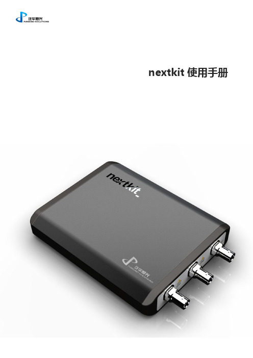
nextkit使用手册概述nextkit 是泛华恒兴为工程师精心设计的一款USB信号万用仪,可实现包括示波器、波形发生器、频率响应分析仪等多种常用仪器功能,更可通过二次开发实现功能自定义,广泛用于产品研发、车载测试、实验室教学、课外工程创新等领域,是除笔记本与万用表之外,随身必备的又一“利器”。
23众所周知,笔记本电脑、万用表一直是工程师的标志,示波器和信号发生器虽然也是常用仪器,但由于其体积因素长期无法实现便携。
nextkit 就是在这方面实现了突破,其首创性地将示波器与信号发生器功能完美结合在一台可手持的USB 仪器中,让工程师随时随地,信号一手掌握。
由于其体积纤小、重量轻,广泛适用于面积狭小的工位操作人员、野外作业环境、移动式车辆操作环境等工作现场;它的优异性能和友好的虚拟软面板工作界面很适合学校实验室、仪器仪表维修现场。
基本性能指标:• 工作温度: 0 - 55摄氏度• 双通道数字存储示波器• 实时采样速率: 200MHz ,可按5,2,1方式向下设置• 垂直分辨率: 8 位• 每通道存储容量: 4k• 量程: 1:1 探头 -10V –10V1:10 探头-100V –100V•输入通道耦合:DC、AC、GND•输入阻抗:1M Ohm / 5pF•输入信号带宽:0Hz –50MHz•任意波形发生器•最高采样速率:50MSa/s•输出波形种类:正弦/方波/三角波/锯齿波/直流/噪声/调制/任意波•输出电压量程:±4Vpp•输出阻抗:50 Ohm•分辨率:12位•数字电压表•电压范围:-100V –100V•输入参数:与示波器一致•频率分析仪(扫频)•扫频范围:1Hz –10MHz•幅频、相频分析•USB 供电模式,无需外接电源•提供现成可用软件(基于nextpad)与DLL及二次开发手册•外形基于人机工程学设计|独特的BNC头保护结构|个性镭雕•于优酷网站提供专业使用指南演示视频4产品组成nextkit 产品包含下列主要部分:nextkit主机一台标准示波器探头:2支USB 电缆:1根BNC双头线:1条配套U盘:1枚(包括所有相关驱动,nextpad软件平台,nextkit软面板,二次开发DLL以及VI,使用说明书,使用教学视频,二次开发文档等)个性LOGO镌刻服务5驱动安装Windows XP如果计算机上没有装过nextkit驱动,当插入nextkit 仪器时就会出现“发现新硬件”,的提示,并弹出安装对话框,这时根据计算机的提示步骤完成仪器驱动安装。
PicoScope 6000 Series 高性能USB波形测试仪说明书

Superior specifications. Great value.Supplied with a full SDK including example programs Windows XP, Windows Vista and Windows 7 From a name you can trust...4 Channels • 500 mh z bandwidth • 5 gs/s sampling • 1 gs memory10,000-waveform bufferx100,000,000 zoom mask limit testing Serial bus decodingUp to 500 mhz spectrum analyzerArbitrary waveform generator Hi-Speed USB 2.0 interfaceArbitrary waveform and function generatorGenerate standard waveforms from DC to 20 MHz (all models) or define your own using the power of the built-in 12-bit, 200 MS/s arbitrary waveform generator (B models only). You can import arbitrary waveforms from data files or draw them using the built-in AWG editor.Spectrum analyzerWith the click of a button, you can open a new window to display a spectrum plot of selected channels. The spectrum analyzer allowsColor persistence modesSee old and new data superimposed, with new data in a brightercolor or shade. This makes it easy to see glitches and dropouts and to estimate their relative frequency. Choose between analog persistence and digital color, or create a custom display mode.High-speed data acquisitionThe drivers and software development kit supplied allow you towrite your own software or interface to popular third-party software packages. If the 1 gigasample record length of the PicoScope 6404B Spectrum analyzerArbitrary waveform generatorPicoScope performance and reliabilityWith 20 years’ experience in the test and measurement industry, we know what’s important in a new oscilloscope. The PicoScope 6000 Series scopes have the best bandwidth, sampling rate and memory depth of any USB oscilloscopes. These features are backed up by advanced software developed with the help of feedback from our customers.High bandwidth, high sampling rateWith a 250 MHz to 500 MHz analog bandwidth complemented by a real-time sampling rate of 5 GS/s, the PicoScope 6000 Series scopes can display single-shot pulses with 200 ps time resolution. ETS mode boosts the maximum sampling rate to 50 GS/s, giving higher timing resolution for repetitive signals.Huge buffer memoryThe PicoScope 6000 Series gives you the deepest buffer memory available as standard on any oscilloscope. Other oscilloscopes have high maximum sampling rates, but without deep memory they cannot sustain these rates on long timebases. The 1-gigasample buffer on the PicoScope 6404B allows it to capture at 5 GS/s down to 20 ms/div for a total duration of 200 ms. To help manage all this two zoom methods. There are zoom buttons as well as an overview window that lets you zoom and reposition the display by simply dragging with the mouse.Advanced triggersAs well as the standard range of triggers found on most oscilloscopes, the PicoScope 6000 Series has a built-in set of advanced triggers to help you capture the data you need.All triggering is digital, resulting in high threshold resolution and excellent waveform stability.Custom probe settingsThe custom probes feature allows you to correct for gain, attenuation, offsets and nonlinearities in special probes, or toconvert to different units of measurement. Definitions for standard Pico-supplied probes are built in, but you can also save your own definitions to disk for later use.Rapid triggeringThe PicoScope 6000 Series contains special triggering hardware to minimise the time between captures. This enables you to collect waveforms at intervals of 1 μs or less when using a short timebase, improving your chances of spotting an infrequent glitch.Deep memory allows you to zoom in... and in... and in6000 Color persistence modesSerial data decoding:CAN • LIN • UART • SPI • I 2CThe PicoScope 6000 Series oscilloscopes are well-suited to serial decoding, with a deep memory buffer that allows them to collect long, uninterrupted sequences of data. This allows the capture of thousands of frames or packets of data over several seconds. The scopes can decode up to four buses simultaneously with independent protocol selection for each input channel.PicoScope displays the decoded data in the format of your choice: “in view”, “in window”, or both at once.“In view” format shows the decoded data beneath the waveformon a common time axis, with error frames marked in red. You can zoom in on these frames to look for noise or distortion on the waveform.“In window” format shows a list of the decoded frames, includingthe data and all flags and identifiers. You can set up filteringconditions to display only the frames you are interested in, search for frames with specified properties, or define a start pattern that the program will wait for before it lists the data.Mask limit testingThis feature is designed for production and debugging environments.Capture a signal from a known working system, and PicoScope will draw a mask around it with your specified tolerance. Connect the system under test, and PicoScope will highlight any parts of thewaveform that fall outside the mask area. The highlighted details persist on the display, allowing the scope to catch intermittent glitches while you work on something else. The measurements window counts the number of failures, and can display other measurements and statistics at the same time.The numerical and graphical mask editors (both shown above) can be used separately or in combination, allowing you to enter accurate mask specifications or modify existing masks. You can import and export masks as files.Digital low-pass filteringEach input channel has its owndigital low-pass filter withindependently adjustable cut-off frequency from 1 Hz to the full Accessories includedInstruction manualSolid tip 0.5 mmCoding rings, 3 x 4 colors Ground lead 15 cm TA133• Instruction manual • Solid tip 0.5 mm• Coding rings, 3 x 4 colors • Ground lead 15 cm Serial data decodingMask limit testingmovable axes: The vertical axes can be dragged up and down. This feature is particularly useful when one waveform is obscuring another. There’s alsoan Auto Arrange Axes command.Automatic measurements: Display calculated measurements fortroubleshooting and analysis. You can add as many measurements as youneed on each view. Each measurement includes statistical parametersshowing its variability.Built-in measurements:AC RMS, True RMS, DC Average, Cycle Time,Frequency, Duty Cycle, Falling Rate, Fall Time, Rising Rate, Rise Time,High Pulse Width, Low Pulse Width, Maximum, Minimum, Peak to Peakmask limit testing:Automatically generate atest mask from a waveformor draw one by hand.PicoScope highlights anyparts of the waveform thatfall outside the mask andshows error statistics.PicoScopeChannels (vertical)6402A 6402B 6403A 6403B 6404A 6404BNumber of channels 4 (BNC connectors)Bandwidth (-3 dB)250 MHz (TA150 probes/50 Ω)200 MHz (±50 mV range)350 MHz (TA150 probes/50 Ω)250 MHz (±50 mV range)500 MHz (TA133 probes/50 Ω)Bandwidth limiterSwitchable, 20 MHz Switchable, 20 MHz Switchable, 25 MHzRise time (10% to 90%, calculated)1.4 ns 1.0 ns 0.7 nsVoltage ranges±50 mV to ±20 V (up to ±5 V when 50 Ω input selected)Sensitivity 10 mV/div to 4 V/div at x1 zoom Input coupling AC or DC (1 MΩ) or DC (50 Ω)Input impedance1 MΩ || 15 pF, or 50 Ω 1 MΩ || 10 pF, or 50 ΩInput offset (position) adjustmentInput range Offset range 50 to 200 mV ±0.5 V 500 mV ±2.5 V 1 V ±2.5 V 2 V ±2.5 V 5 V ±20 V (50 Ω: ±0.5 V)10 V ±20 V 20 V ±20 V Input range Offset range 50 to 200 mV ±2 V 500 mV ±10 V (50 Ω: ±5 V)1 V ±10 V (50 Ω: ±4.5 V)2 V ±10 V (50 Ω: ±3.5 V)5 V ±35 V (50 Ω: ±0.5 V)10 V ±30 V 20 V ±20 VDC accuracy3%Overload protection±100 V to ground (1 MΩ inputs), 5.5 V RMS (50 Ω inputs)Timebase (horizontal)Timebases (real-time sampling)10 ns/div to 1000 s/div Timebases (equivalent-time sampling/ETS)1ns/div to 1000 s/divTimebase accuracy5 ppmAcquisitionADC resolution8 bits (up to 12 bits in resolution enhancement mode)Maximum real-time sampling rate5 GS/s (one channel enabled), 2.5 GS/s (two channels enabled), 1.25 GS/s (three or four channels enabled)Maximum equivalent-time sampling (ETS) rate 50 GS/s (any number of channels)Buffer size (shared between active channels)128 MS 256 MS 256 MS 512 MS 512 MS 1 GS Maximum buffer segments 125 000250 000250 000500 000500 000 1 000 000Maximum streaming data rate1 MS/s in PicoScope software. >10 MS/s using supplied SDK (PC-dependent)TriggerBasic triggers Rising, fallingAdvanced triggers Edge, Pulse width, Window, Window pulse width, Dropout, Window dropout, Level, Interval, Logic level, Runt pulseTrigger modes None, Single, Repeat, Auto, Rapid, ETS Maximum trigger rate Up to 10,000 waveforms in a 10 ms burstTrigger timing resolution1 sample period Trigger sources Channels A to D, AUXTrigger level Adjustable over whole of selected voltage rangeRe-arm timeLess than 1 μs on fastest timebaseMaximum pre-trigger capture 100% of capture size Maximum post-trigger delay4 billion samplesAUX inputExternal clock inputReference frequency 5 MHz to 25 MHzInput type50 Ω, BNC, ±1 V threshold adjustment range, ±5 V protection range, DC coupled Function generator and arbitrary waveform generator (AWG)Function generator frequency range DC to 20 MHzFunction generator waveforms (A models)Sine, square, triangle, DCFunction generator waveforms (B models)As A models plus ramp, sin (x)/x, Gaussian, half-sine, white noise, PRBSDAC resolution / DC accuracy12 bits / 1%Amplitude range ±250 mV to ±2 VOffset adjustment ±1 V (max. combined output ±2.5 V)Output impedance 50 ΩAWG buffer size N/A 16 kS N/A 16 kS N/A 16 kS AWG sample rateN/A 200 MS/s N/A 200 MS/s N/A200 MS/sProbe calibration outputSignal output type1 kHz square wave,2 V pk-pk, 600 ΩSpectrum analyzerFrequency range DC to 250 MHzDC to 350 MHz DC to 500 MHzDisplay modes Magnitude, average, peak holdWindowing functions Rectangular, Gaussian, triangular, Blackman, Blackman-Harris, Hamming, Hann, flat-topNumber of FFT pointsSelectable power of 2 from 27 to 220Math channelsFunctions −x, x+y, x−y, x*y, x/y, x^y, sqrt, exp, ln, log, abs, norm, sign, sin, cos, tan,arcsin, arccos, arctan, sinh, cosh, tanh, freq, derivative, integral, min, max, average, peakOperandsInput channels A to D, reference waveforms, time, πSerial bus decodingBaud rate10 kb/s to 1 Mb/s, auto-detect with manual overrideThreshold voltageAuto or manualData formatsCAN, LIN, I 2C, UART/RS-232, SPIMask limit testingStatisticsPass/fail, failure count, total count DisplayInterpolation Linear or sin (x)/xPersistence modesDigital color, analog intensity, custom, or noneGeneralDimensions (including connectors and end caps)255 x 170 x 40 mm (approx. 10.0” x 6.7” x 1.6”) 280 x 170 x 40 mm (approx. 11.0” x 6.7” x 1.6”)Weight1 kg (approx.2 lb3 oz) 1.3 kg (approx. 2 lb 14 oz)Operating temperature range0 °C to 40 °C (20 °C to 30 °C for stated accuracy)Compliance EU: EMC, LVD, RoHS, WEEE. USA: FCC Part 15 Class APC connection USB 2.0 (USB 1.1 compatible)Power supplyAC adapter and cable (cord) suppliedLanguages supportedSimplified Chinese, Traditional Chinese, Czech, Danish, Dutch, English, Finnish, French, German, Greek, Hungarian, Italian, Japanese, Norwegian, Polish, Portuguese, Romanian, Spanish, Swedish, TurkishP i c o S c o p e 6000 S e r i e s P C O s c i l l o s c o p e sSpecificationsPico Technology, James House, Colmworth Business Park, St. Neots, Cambridgeshire, PE19 8YP, United Kingdom ☎ +44 (0) 1480 396 395 +44 (0) 1480 396 296✉******************* Prices are correct at the time of publication. Please contact Pico Technology for the latest prices before ordering. Errors and omissions excepted. Windows is a registered trademark of Microsoft Corporation in the United States and other countries. Pico Technology, PicoScope and PicoLog are internationally registered trade marks of Pico Technology Ltd..Ordering informationDescriptionPicoScope 6402A 250 MHz Oscilloscope with probesPicoScope 6402B 250 MHz Oscilloscope with AWG and probes PicoScope 6403A 350 MHz Oscilloscope with probesPicoScope 6403B 350 MHz Oscilloscope with AWG and probes PicoScope 6404A 500 MHz Oscilloscope with probesPicoScope 6404B 500 MHz Oscilloscope with AWG and probes Replacement x10 probe for PicoScope 6402A/B & 6403A/B Replacement x10 probe for PicoScope 6404A/BHave you seen the PicoScope 6407 Digitizer?The PicoScope 6407 Digitizer has four 1 GHz inputs and a maximum sampling rate of 5 GS/s. See for more information.Product pack contents• PicoScope 6000 Series oscilloscope • Four factory-compensated probes • USB cable• Universal mains (AC) power supply • Mains lead (power cord)• Installation Guide• Software and Reference CD • Carrying caseMM023-7. Copyright © 2011-2012 Pico Technology Ltd. All rights reserved.。
USB插拔试验机操作规程

6、待测试结束(也可能为设定次数到达,机器自动停机),关掉机器电源,取下被测试件,判定其品质。
注
意
事
项
1.检查试验产品夹持是否稳固,USB口是否平稳的插入产品中,插拔是否精准。
2.实验前检查参数是否清零,转速调试合适方可开机试验.
深圳市欧力科技有限公司
文件编号
WI—011-007
制订日期
2019-3-30
USB插拔寿命试验机操作规程
版本
A/0
页次
1/1
操
作
说
明
1、放置注意地面之平坦,安装时请调整机器水平;
2、将插试件一头放入左边夹具内夹紧,然后再将插试件的另一头插入试件中。打开右边夹具,手动转动圆盘,转动至最大行程时,看右边夹具是否能够将试件夹到。如果不能再调节圆盘边上行程调节旋钮,加大行程(一般来讲尽量将试件夹入多一点为好);然后再紧固右边夹具,使试件在同一平行水平面上无张力
3.试验完成后,产品状况进行测试并记录。已达到测试目的。4.使用完后关ຫໍສະໝຸດ 试验机电源。制表审核
批准
3、接入220V电源,按下电源开关,指示灯亮;
4、在计数器上进行设定所需插拔次数,(当机器运行达到设定数值时,运行停止;需要再次启动,按计数器清零键清零,机器恢复下常工作状态)。设定数值最大为8位数99999999,设定好的数值将在计数器的下方显示。调节速度钮至最小值,按启动键,机器启动,观察试件插入是否在中心位置上。如有异常请停机,再一次将夹具调节好。计数器设置方法:按复位键将计数器归零。根据要求设定需测试次数,计数器最大可设定99999999次。按计数器上的RST键将计数器清零,按>键五秒进入试验次数设置,计数器上八位数字从右下到左上分别代表个位到千万位,如设定280360次,则按>键将跳动数值调节到左上第三个数字按∧键将数值设定为2,再按>键将跳动数值调节到左上第四个数字按∧键将数值设定为8,再按>键将跳动数值调节到右下第三个数字按∧键将数值设定为3,再按>键将跳动数值调节到右下第二个数字按∧键将数值设定为6,其它位置均设定为零即可,根据试验要求设定试验所需次数,将测试次数清零后,按启动开始测试;
网络版款彩屏中文机说明书

网络版彩屏中文机说明书目录USB驱动安装 (1)一、驱动安装 (1)二、查看设备 (3)使用说明 (5)一、系统设置及使用 (5)1. 启动系统 (5)2.资源管理 (5)二、资源设置 (7)1. 人员设置 (7)2. 地点设置 (7)3. 事件设置 (8)4. 棒号设置 (9)5. 地点事件设置 (10)6. 系统设置 (10)三、设置功能 (11)1. 线路设置 (11)2. 计划设置 (12)3. 下载档案 (12)四、下载数据 (13)1. 采集数据 (13)2. 计划实施 (14)USB驱动安装一、驱动安装第一次安装完软件后,请将巡检器用USB传输线与电脑连接好,系统自动出现如下画面:选择第一个选项(是,仅此一次),单击下一步,出现:选择第二个选项(从列表或指定位置安装),单击下一步,出现:选择在搜索中包括这个位置,点击浏览,选择USB驱动所在的文件夹,单击下一步,出现:单击完成,则USB驱动安装成功。
二、查看设备安装完USB驱动后,您可以在设备管理器中查看所用的串口号,选择我的电脑按右键选择属性,在属性中选择硬件,点击设备管理器,在管理器中选择端口(COM和LPT),出现CP2101 USB to UART Bridge Controller (COM3),则您在软件中应用的串口号则为COM3。
具体过程如下图所示:然后在软件的系统设置里面更改串口号为“com3”,如图:使用说明一、系统设置及使用1.启动系统软件安装完成后,即可在开始|程序|指纹中文机中,单击"指纹中文机"项,系统启动,并出现登录窗口。
如果是第一次使用本系统,请选择管理员登录系统,口令为"admin",这样您将以管理员的身份登录到本系统。
系统启动后出现如上图示各菜单操作,第一次使用本系统进行日常工作之前,应建立必要的基础数据,如果需要,应修改系统参数。
2.资源管理(1)人员管理在该界面中可以进行登录人员的设置,点击添加按钮,系统则自动增加一个人员的信息,双击用户名、密码、操作权限的单元格可以修改相应的信息,双击单位的单元格可以为新增加的人员选择登录部门。
RS Pro 2205A-20 USB数字波形测试仪说明说明书
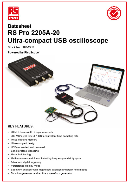
KEY FEATURES:• 20 MHz bandwidth, 2 input channels• 200 MS/s real-time & 4 GS/s equivalent-time sampling rate• 16 kS capture memory• Ultra-compact design• USB-connected and poweredMath channels and filters, including frequency and duty cycle Advanced digital triggeringPersistence display modeSpectrum analyser with magnitude, average and peak hold modes Function generator and arbitrary waveform generatorSPECIFICATIONSRS Pro 2205A-20VERTICAL Channels2Bandwidth20 MHzRise Time (calculated)17.5 nsInput Ranges±50 mV to ±20 V (1-2-5 increments)Input Sensitivity10 mV/div to 4 V/div (10 vertical divisions)DC Accuracy±3% of full scale ±200 μVInput Coupling AC / DCInput Characteristics 1 MΩ ± 1%, 15 pF ± 2 pFTRIGGER Sources Ch A, Ch BTrigger Modes None, Auto, Repeat, SingleTrigger Types Edge, Window, Pulse Width, Window Pulse Width, Dropout, Window Dropout, Interval, LogicTrigger Sensitivity Digital triggering provides 1 LSB accuracy up to full bandwidthHORIZONTAL Range 5 ns/div to 5000 s/div (1-2-5 increments)Initial Timebase Accuracy±100 ppmPre-Trigger Up to 100% of capture sizePost-Trigger Up to 4 billion samplesSIGNAL ACQUISITION Real-Time Sample Rate 1 ch.2 ch.200 MS/s (Ch. A) 100 MS/sEquivalent-Time Sample Rate 4 GS/sUSB Streaming Sample Rate Up to 1 MS/sVertical Resolution8 bitsEnhanced Vertical Resolution Up to 12 bitsCapture Memory (Block Mode)16 kS (shared between active channels)Capture Memory (USBStreaming)100 MS (shared between active channels)Max. waveforms in buffer10 000Capture Modes Scope, Spectrum, PersistencePersistence Modes Digital colour, analogue intensity, custom, fast or noneSPECTRUM ANALYSER Frequency Range DC to analogue bandwidth of oscilloscopeDisplay Modes Magnitude, average, peak holdWindowing Functions Rectangular, Gaussian, triangular, Blackman, Blackman-Harris, Hamming, Hann, flat-topNumber of FFT Points Selectable from 128 to half available capture memory in powers of 2SIGNAL GENERATOR Operates As Function generator, arbitrary waveform generator (AWG)Output Signals Sine, square, triangle, DC voltage, ramp, sinc, Gaussian, half-sine, arbitraryStandard Signal Frequency DC to 100 kHzSweep Modes Up, down, dual with selectable start/stop frequencies and incrementsOutput Frequency Accuracy Oscilloscope timebase accuracy ± output frequency resolutionOutput Frequency Resolution< 0.02 HzOutput Voltage Range±2 VOutput Adjustments Any amplitude and offset within ±2 V rangeAWG Update Rate 1.548 MHzAWG Buffer Size 4 kSAWG Resolution12 bitsAWG Bandwidth> 100 kHzAWG Rise Time (10% to 90%)< 2 µsSERIAL DECODING Protocols1-Wire, ARINC 429, DCC, DMX512, I²C, LIN, Modbus ASCII, Modbus RTU, PS/2, SPI, SENT,UART/RS-232, USB 1.1MATH CHANNELS Functions−x, x+y, x−y, x*y, x/y, x^y, sqrt, exp, ln, log, abs, norm, sign, sin, cos, tan, arcsin, arccos, arctan,sinh, cosh, tanh, freq, derivative, integral, min, max, average, peak, delay, duty, highpass,lowpass, bandpass, bandstopOperands A, B (input channels), T (time), reference waveforms, constants, piSPECIFICATIONSRS Pro 2205A-20RULERS AND MEASUREMENT Scope Measurements AC RMS, true RMS, frequency, cycle time, duty cycle, DC average, falling rate, rising rate,low pulse width, high pulse width, fall time, rise time, minimum, maximum, peak to peak, edgecount, falling edge count, rising edge countSpectrum Measurements Frequency at peak, amplitude at peak, THD dB, SNR, SINAD, SFDR, total power, averageamplitude at peak, THD %, THD+N, IMDStatistics Minimum, maximum, average and standard deviation, capture count, spanMask Limit Testing Statistics Pass/fail, failure countRuler Measurements Amplitude rulers, time rulers, frequency rulers, phase rulersINTERFACE PC connectivity USB 2.0 (USB 3.0 compatible). USB cable included.Power requirements Powered from USB portENVIRONMENTAL Temperature range, operating0 °C to 50 °CTemperature range, operating,for stated accuracy15 °C to 30 °CTemperature range, storage–20 °C to +60 °CHumidity range, operating5% to 80% RH non-condensingHumidity range, storage5% to 95% RH non-condensingAltitude Range Up to 2000 mPollution Degree2Safety approvals Designed to EN 61010-1:2010Environmental approvals RoHS, WEEEEMC approvals Tested to meet EN61326-1:2013 and FCC Part 15 Subpart BGENERAL Free Software Available forDownloadPicoScope 6 for Microsoft Windows 7, 8 and 10; 32-bit and 64-bitLanguages Supported Simplified Chinese, Czech, Danish, Dutch, English, Finnish, French, German, Greek,Hungarian, Italian, Japanese, Korean, Norwegian, Polish, Portuguese, Romanian, Russian,Spanish, Swedish, TurkishDimensions142(D) x 92(W) x 18.8(H) mm including connectors and feetWeight< 0.2 kgORDERING INFORMATIONRS Pro 2205A-2020 MHz, 2-channel USB PC oscilloscopeACCESSORIES INCLUDEDQuick Start Guide ×1, Data Sheet ×1, USB 2.0 cable ×1TA208 set of two 60 MHz (10:1/1:1) passive probesFREE DOWNLOADPC Software PicoScope 6 softwareDocumentation Quick Start GuideData SheetRS Components Ltd.Birchington Road Corby NorthantsNN17 9RSUK Tel.: 08457 201201Web: DO302-1。
USB上下电测试仪使用说明书
USB上下电测试仪使用说明书B上下电测试仪产品特性✓机械开关接通、断开,完全模拟手工插拔过程✓支持USB1.1/2.0的LS低速/FS全速/HS高速、USB3.0/3.1的SS超高速。
✓可以测试USB主机(HOST)或者USB设备(DEVICE)频繁上下电(通断电)✓适用于USB产品的开发/测试/生产各个环节✓开关寿命10万次✓免驱动,插上电脑,打开程序就可以操作!✓支持VB/VC/C#/Delphi/Labview/易语言/按键精灵,只要能调用VC DLL都可以;支持Linux,支持树莓派,支持Openwrt。
✓提供管理工具及源码;只需一条USB线,无需外接电源,简单易用。
✓提供VB/VC例程源代码。
✓支持32位/64位windows2000/xp/vista/win7/win8✓一台电脑最多可以同时接126个✓全速USB HID接口,无需安装驱动、应用软件,即插即用。
✓命令接口简单易用✓提供应用程序例程和DLL以及静态链接LIB,可以自己开发没有DLL的应用程序B上下电测试仪USB上下电测试仪是一个可以在电脑上运行程序控制的USB上下电开关。
采用免驱动HID的通讯协议,即插即用,无需安装任何驱动。
上图左侧的两个USB母头,支持USB2.0/3.0低速、全速、高速、超高速。
USB Device和USB Host任意接到其中一个母头即可,没有区别。
3.注意事项3.1.PC软件支持32/64位Windows2000及以上操作系统我们提供DLL及静态链接库。
在64位Windows操作系统上,PC端应用软件必须编译成X86模式,不能编译成X64或者AnyCpu模式。
一般在Visual Studio中如下设置:3.2.不要多进程同时操作一个USB上下电测试仪USB上下电测试仪支持多线程,也就是在一个exe里多个线程同时操作一个USB上下电测试仪,是可以的。
但建议不要多进程操作一个USB上下电测试仪,就如同多个人同时操作一份文档一样,如果多个进程(比如多个exe)同时操作一个USB上下电测试仪,USB上下电测试仪的状态将是不可知的。
歌诗德 U18 高性能 USB 数字音频界面 使用说明书
GustardU18高性能USB数字音频界面使用说明书目录前面板介绍 (2)后面板介绍 (2)显示屏及操作菜单 (3)HDMI-IIS线序展示 (4)驱动安装 (5)foobar2000实现DSD硬解的设置 (8)foobar2000未能DSD问题解答 (13)产品参数 (17)售后服务 (18)前面板1.显示屏显示当前工作采样率、时钟源状态以及多功能BNC接口输出信号类型状态。
2.REF——时钟参考源选择功能,用以选择界面的时钟源是用本地时钟还是由外部10M合成。
3.IIS——用以调整HDMI-IIS接口的模式,短按切换线序,长按调整DSD FLAG。
后面板显示屏及操作菜单1.U18高性能数字界面使用高分辨率OLED显示屏,实时状态显示以及功能操作。
以下图形为屏幕主页面显示状态。
2.时钟参考源选择(REF):借由歌诗德开发的K2——第二代音频时钟频率合成器,U18高性能数字界面可以使用外部10M 输入来进一步提升音质。
按下功能按键区域左边REF按键,可以在本地时钟(显示为INT)以及外部10M(显示为EXT)之间选择。
本地时钟使用的是2枚美国ACCUSILICON AS338超低相噪HI-END飞秒时钟源。
* 安全起见,接入外部10M时钟后,本机不会自动切换时钟源,必须手动选择内外时钟源。
* 当切换到外部10M时钟源为稳定、准确的信号时。
U18可以保持完全正常工作。
否则会显示EXT ERR 且采样率会持续闪烁IIS线序调整(IIS):U18手动设置HDMI-IIS输出接口的线序:共有 GUSTARD、MODE2、MODE3、MODE4 总共4种模式可选GUSTARD为歌诗德模式,后端为歌诗德解码时选择此模式MODE2、MODE3、MODE4的线序如下图所示F14/F15/F16为可调的DSD FLAG引脚位,通过长按IIS按键操作。
*GUSTARD模式下无需调整DSD FLAG,直接配合,故无显示和调整。
测试仪的使用说明
测试仪的使用说明一.介绍测试仪是一种用于测量和检测各种电气参数的仪器。
它广泛应用于工业生产、电力系统、通信领域等各个行业。
本使用说明将帮助用户了解和正确操作测试仪,使其能够准确、有效地测量和检测电气参数。
二.安全操作1.在使用测试仪之前,务必熟悉并遵守所有相关的安全规定和操作指南。
2.使用测试仪时,应注意身体和设备的安全,避免发生触电、触及高温部件、烧伤等危险。
3.如果测试仪出现故障或损坏,应停止使用并寻求专业维修人员的帮助。
三.使用前准备1.仔细阅读测试仪的说明书,了解其功能、技术参数和操作方法。
2.检查测试仪的各个部分是否完好无损,如显示屏、控制按钮、连接线缆等。
如有损坏,应及时更换或修理。
3.储备所需的测试仪配件和附件,如电池、测试夹子、测试针等。
四.连接与使用1.将测试仪连接到电源或电池上,确保供电正常。
2.选择所需的测量参数,并调整测试仪的量程和功能。
在调整前,可通过查阅技术参数来确保选择正确的量程范围。
3.使用测试仪时,应将测量引线正确连接到测试样品或电路上。
确保引线与电路接触良好,无松动和断开的情况。
4.在测量过程中,要保持手持测试仪的稳定和准确。
避免突然晃动或移动导致不准确的测量结果。
5.如需改变测量参数,应先停止测量并作出相应的调整,然后重新启动测量过程。
6.测量结束后,应断开测试样品或电路的连接,并关闭测试仪的电源,避免电池耗尽或造成不必要的能源浪费。
7.使用后应将测试仪放置在干燥、通风良好的地方,避免受潮或存放在高温或低温环境中。
五.常见问题与解决方法1.测试仪无法正常开机:-检查是否有足够的电源供应,如电池电量是否足够或电源是否供电正常;-检查测试仪是否损坏,如是否需要更换显示屏、控制按钮等组件。
2.测试结果不准确:-检查是否选择了正确的测量参数和量程范围;-检查测量引线是否与测试样品或电路良好接触;-检查测试仪是否受到外部电磁干扰,如靠近强磁场、高频干扰等;-检查测试仪是否需要校准,如需要,应及时进行校准操作。
USB线材测试仪作业指导书

USB线材测试仪作业指导书工站名称:成品测试使用设备:线材测试仪输入电压:220VAC一、操作步骤:1、开机前,检查测试机是否完好可用,治具是否正常无损,把测试机的AB端与治具的AB 端连接好(A-A,B-B)。
2、在测试机背部插上220V电源,把开关打向“I”接通电源,等待屏幕显示“无线缆插入???请插入线缆...”,说明开机完成,测试机已准备好。
3、每班首次使用测试机时应用良品与不良品进行点检。
校验合格,方可进行正常测试,校验不合格,必须通知技术人员进行维修并再次校验,直至合格。
4、点检完成后,即可进行测试。
先把线的USB公头插入并插满治具A端,然后把母头插治具B端进行测试。
5、测试合格时,屏幕显示“通过”,正确绿灯亮起,并发出“嘟”声。
测试不合格时,屏幕显示“错误”,错误红灯亮起,不发出声音。
如有不合格产品,应立即拔出放入指定红框内。
6、屏幕显示的是合格数量,如需清零,则应关电重启。
“A=02 B=02”表示当前测试的线材是两芯线。
7、将测试好的线整理整齐摆放。
(作业完成后,按照要求摆放好成品和不良品,做好不良品标识。
)8、如需更换产品规格,则需先拿合格的产品连接好读取资料。
先拿合格产品连接治具AB 端,开启电源,屏幕亮时应快速按两次红色的学习按钮,读取资料并显示线材的总pin数(此步骤需由工程师或生技人员操作。
)二、点检作业要求:1.点检要具备的物品:①测试确认表②反测试样品线③测试冶具④确认参数与作业指导书一致。
2.点检失败判定方式:测试线测试完后,在USB测试机上的结果跟线上标签显示的不良方式不同,则判定点检失败。
例如:测试线是错线,USB测试机显示的是其它性能不良,则判定点检失败,也可能为机台故障。
3.出现点检失败的,操作员必须通知当班组长,由组长联系相关维修人员对USB测试机进行故障认定及维修。
4.维修完后,操作员必须对USB线材测试机再进行一次点检,点检OK,品管确认签名后方可量产。
USB 分析仪使用说明.
六、软件的安装与使用 在光盘的 software 目录里双击 Setup.exe 然后应用程序和驱动程序都会安装上了。软件安装完毕后,只
要连接上 USB 分析仪就可以使用了。注:USB 分析仪的软件驱动程序在软件打包里,请先安装软件后再 连接 USB 分析仪。
连接上监控计算机的 USB 线后,计算机会出现如图 5 的提示。
查找错误数据,其对话框如图 23 所示。
图 23 查找错误对话框 可以选择的错误方式有: 错误的 PID:表示 USB1.1 协议内不存在的 PID。 位缓冲错误:表示 USB 总线上受到干扰或不符合 USB 总线规定的传输错误。 错误的 CRC5:USB 传输令牌过程中传输的 CRC5 与校验出来的 CRC5 不同的地方。 错误的 CRC16:USB 传输数据过程中传输的 CRC16 与校验出来的 CRC16 不同的地方。 查找数据字符串:
SOF、SETUP、DATA0、DATA1、ACK、NAK、STALL、PRE。 由于本分析仪记录深度比较大,建议才用人工触发,把所有数据都采集后在进行数据分析。 连接选择为选择采集端数据的速度类型,请按照设备的类型进行选择全速或低速设备。其中,一般
USB 键盘和鼠标都为低速设备。当选择不正确时,由于全速设备和低速设备的采样频率不同,会造成数据 的错误。
图 7 寻找驱动程序 如果使用 Windows XP 或 Windows 2000 操作系统,会有图 8 的提示。
图 8 Windows 徽标提示 点击仍然继续,就开始复制驱动程序,安装完后,会有如图 9 的提示。
图 9 完成新硬件向导 -4-
广州周立功单片机发展有限公司 Tel: (020)38730976 38730977 Fax: 38730925 点击完成就可以了,且右下方会出现如图 10 的新硬件安装完成的提示。
USB 分析仪使用说明.

图 7 寻找驱动程序 如果使用 Windows XP 或 Windows 2000 操作系统,会有图 8 的提示。
图 8 Windows 徽标提示 点击仍然继续,就开始复制驱动程序,安装完后,会有如图 9 的提示。
图 9 完成新硬件向导 -4-
广州周立功单片机发展有限公司 Tel: (020)38730976 38730977 Fax: 38730925 点击完成就可以了,且右下方会出现如图 10 的新硬件安装完成的提示。
图 29 解码设备请求对话框
- 10 -
广州周立功单片机发展有限公司 Tel: (020)38730976 38730977 Fax: 38730925 如图 30 为一个对 Packet #1318 进行解码的结果。
二、系统要求 (1)监控计算机
Pentium IV 1.0G 以上或 100%兼容 CPU USB 2.0 接口 128M 内存以上 500M 硬盘空间 CD-ROM 或 DVD-ROM 驱动器 Windows 98,Windows 2000,Windows XP 或更高操作系统(推荐使用 Windows XP 或 Windows 2000) (2)调试主机 符合通用主机控制器(UHC)或开放主机控制器(OHC)规范的设备(如个人计算机、工业计算机、 笔记本电脑、PDA 等)
Gossen MAVO-MONITOR USB 光线测量仪操作指南说明书
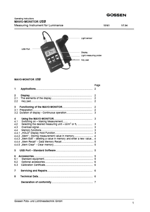
Operating InstructionsMAVO-MONITOR USBMeasuring Instrument for Luminance 151611/7.04MAVO-MONITOR USBPage1 Applications (2)2 Display (2)2.1 The elements of the display (2)2.2 Key pad (2)3 Functioning of the MAVO-MONITOR (2)3.1Preparation (2)3.2 Duration of display - Continuous operation (3)4 Using the MAVO-MONITOR .......................................................34.1 Switching on – Making Measurement.......4.2 Selecting the desired measuring unit – cd/m 2 or fL .....................34.3 Overload signal.............................................................................34.4 Memory functions..........................................................................34.4.1 …HOLD“ Display Hold Function......................................................34.4.2 …Mem“ - Storing measurement value in memory...........................44.4.3 …Mem Edit“ - deleting a value in memory and enter a new value...44.4.4 …Mem Recall“ - Data Memory Recall..............................................54.4.5 …Mem Clear“ - Clear memory.........................................................55USB Port – Standard Software (5)6 Accessories (5)6.1 Standard equipment (5)6.2 Optional accessories (6)6.3 Calibration Certificate....................................................................67 Servicing and Repairs (6)8 Technical Data (6)Declaration of conformity ...........................................................7USB Port1 ApplicationsThe MAVO-MONITOR Luminance Meter is a handy, easy to use and high precision measuring instrument. It allows the accurate measurement of the luminance in cd/m² or fL. The MAVO-MONITOR is ideally suited for contact measurements with the light measuring probe placed direct on luminous or backlighted surfaces (monitors, TV sets,light boxes, light panels). When combined with the MAVO-SPOT Attachment (optional accessory), it can be used for spot metering the luminance at a distance from 34 cm to ∞, the measuring angle being 1 degree. (Monitors, with the ambient light being taken into consideration in the measurement - lighting and illumination of work stations, streets, airports, museums, projection screens). The light sensor is color corrected, i.e. its spectral responsitivity has been matched to the spectral photonic vision of the human eye (V λ). The accuracy class for luminance meters has been defined in the Standard Specification DIN 5032, Part 7. The MAVO MONITOR fully complies with the requirements of ClassB.Consequently all the important types of light can be measured with high precision, without the necessity to apply additional corrrection factors. The MAVO-MONITOR is provided with a data memory with 100 measurement value locations, which can be read and processed direct with the keys and display, but also through the integrated USB Port and the standard software provided with the instrument.cd/m² = Candela per m² 1 cd/m2 = 0.2919 fL = 0.0929 cd/ft2fL = footLambert 1 fL = 3.426 cd/m2 = 0.3183 cd/ft21 cd/ft2 = 10.76 cd/m2 = 3.142 fL2 Display2.1Description of display 2.2 Key pad1 Display of measured value and1Switching on/offMemory indication 2Range key – Memory/Measuring range2 Measurement Unit 3cd/m2fL- Select measurement unit3 Display …HOLD… indication4Hold - Function4 Multiplying factor for measurement value5Range key – Memory/Measu5 Auto ranging – automatic range selection6Mem – Memory key6 Low Battery3Functioning of the MAVO-MONITOR3.1PreparationFirst remove the snap-on cover and open the battery compartment at the back of the meter. Insert the battery included with the meter (1.5 V size AA, IEC LR6) in the battery compartment.Care should be taken to place the battery correctly accordingto the polarity indications “+“ and “-“ in the battery compartment.When the battery warning symbol ( ) appears in the display,the battery must be replaced.The values in the measurement data memory and also the presetindividual values will be maintained, even when the battery is changed.3.2 Duration of Display – Continuous operationIf for approx. 4 minutes none of the keys of the MAVO-MONITOR is pressed, the instrument will be switched off automatically. During the last 4 seconds before automatic switch off an acoustic signal will sound. By pressing any one of the keys, you can override the automatic switch off. When the instrument is switched off, the values stored in the data memory and also the preset individual values will be maintained.You can override the automatic switch off, when switching on the instrument and simultaneously keep the HOLD key depressed.The measuring unit (cd/m² or fL) in the display will blink and indicate that the continuous operation mode is on.4Using the MAVO-MONITOR4.1Switching on – Making MeasurementPress the on/off key and the MAVO-MONITOR is immediately in the measuring mode and is measuring at the rate of 2 times per second. The instrument is in the function …AUTO“, i.e. the MAVO-MONITOR willselect the best suited measuring range for the existing light level. By pressing one of the range keys, one of the measuring ranges can be locked. Browsing up or down through additional measuring ranges isaccomplished by briefly pressing one of the range keys. If both keys are pressed and held simultaneously,the instrument is returned to …AUTO RANGING“.4.2Selecting the desired measurement unit cd/m 2or fL Use the key cd/m 2 fL to select the desired unit for the read-out – cd/m² or fL.4.3Overload DisplayWhen exceeding one of the measuring ranges …OL“ (Overload) appears in the display.4.4Memory FunctionsThe MAVO-MONITOR is provided in addition to the …Display Hold“ also with a memory for data up to 100measurement values.This function allows several measurement operations in the field and read-out at a later time. The data stored in the memory will be maintained, even when the instrument is turned off or the battery is changed.4.4.1…HOLD“ Display Hold FunctionThe display HOLD function allows you to measure even at very low light levels, where it would be difficult to read the display. By pressing the HOLD key, the last value measured is held on the display to be read at brighter light. Pressing the HOLD key again will return the MAVO-MONITOR to the measuring function.The function HOLD is the basic function for all the memory functions.674.4.2…Mem“ – Storing measurement value in memoryThe measurement value to be memorized is locked by the Hold key in thedisplay. By pressing the key Mem you will enter the value to be stored inthe next free memory location. An acoustic signal confirms …value stored inmemory“.The display indicates the stored measurement value alternating with thenumber of the memory location for a few seconds. Subsequently, theMAVO-MONITOR will return to the measuring function. When the memoryis completely filled, the display will show …FLL“.4.4.3…Mem-Edit“ – Deleting a value in memory and entering a new valueThe Mavolux offers the function …Mem Edit“ for correcting a value stored inthe memory. Measure again, press the Hold key and the new value islocked. Then by pressing one of the range keys, you can browse throughthe memory.At the memory location to be corrected press nowthe key Mem . An acoustic signal confirms …valuestored in memory“. In the display the measurementvalue stored is indicated for a few secondsalternating with the number of the memorylocation. Subsequently theMAVO-MONITOR will return to measuringfunction.4.4.4…Mem Recall“ –Data memory RecallStart in the function …Measuring“ and press the key Mem.Press one of the range keys to browse through thedata memory. The current memory location isindicated in the display alternating with themeasurement value stored in the memory.By pressing any one of the other keys or when forabout ten seconds no further memory data will berecalled with the Range keys, the MAVO-MONITOR will return to the measuring function. 4.4.5…Mem-Clear“ – Clear memoryThe MAVO-MONITOR must be in function …HOLD“.When pressing simultaneously the Range keys, you clear the complete measuring data memory. The cancelling is confirmed by an acoustic signal and three dashes in the display.5USB Port – Standard SoftwareThe MAVO-MONITOR is equipped with a USB Port which allows the meter to be connected to a PC with the USB cable (supplied).The CD Rom supplied with the MAVO-MONITOR contains, among other information, a Standard Software which allows you to start the PC operation immediately.More details about the PC operational functions are also available on that CD-Rom.6Accessories6.1 Standard Equipment- Leather carrying case-Battery-Standard Software on CD-ROM-USB-cable-Instruction Manual6.2 Optional Accessories- MAVO-SPOT (ordering no. M494G) AttachmentFor precision spot metering of the luminance, non contact, at a distance from 34 cm to ∞, withmeasuring angle of 1 degree. The ambient light is being taken into consideration in the measurement.The light sensor is color corrected, i.e. its spectral responsitivity is adapted to the photonic vision of the human eye. (V λ) according to DIN 5032, Part 7, Class B. TheMAVO-MONITOR with attached MAVO-SPOT is especially suited for inspecting and constancy testing of viewing monitors in medical imaging applications according to DIN 6868/57. Other applications: Projection screens, street surfaces and street lighting, illumination of tunnels and sport areas.- CALCULATOR, calculating disk (ordering no. 5999V0380)For converting the value measured with the MAVO-MONITOR into photographic shutterspeed/f-stop combinations based on the film speeds.6.3Calibration Certificate (Optional)Calibration reference: Scientific Standard Lamps, type Wi 41G of the PTB (Physikalische Technische Bundesanstalt Braunschweig – National Standard Institute of Germany). Depending on how the instrument is being used we recommend a recalibration interval between 12 and 18 months. For this purpose please13contact our Calibration Service Department (telephone +49 911 8602 172).7Servicing and RepairsNo special maintenance is required, if the MAVO-MONITOR is handled correctly.Keep the outside surfaces clean. Use a slightly dampened cloth for cleaning. Do not use cleansers, abrasives or solvents.Should the instrument nevertheless not work to your satisfaction or if you will require repeated calibration with Test Certificate, please send the MAVO-MONITOR to:GOSSEN Foto- und Lichtmesstechnik GmbHThomas-Mann-Strasse 16 – 20D – 90471 Nürnberg8Technical DataLight Sensor Silicon photo diode with V (λ) filterClassification Class B according to DIN 5032, Part 7 (CIE 69)Measuring Rate 2 measurements per secondLCD display50 mm x 25 mmRead-out 7 segments, 31/2 digits, 13 mmOverload signal…OL“ in the displayMemory for measurement values100 memory locations, display indication …FLL“ = memory fullPort USB 1.1Power SupplyBattery one 1.5 V alkaline – manganese cell, size AA (IEC LR 6) or suitable rechargeable battery Battery life approx. 45 hours continuous operation with alcaline – manganese batteryBattery test Automatic display of … … symbol, when battery voltage drops below 1.0 Volts External When the MAVO-MONITOR is connected to a PC, power will be supplied by the PC via the USB cable.Weights and DimensionsHousing PlasticsDimensions Measuring instrument: 65 x 120 x 19 mm (2,56 x 4,73 x 75“)(without carrying case)Measuring Probe:31 x 105 x 30 mmWeight Measuring instrument with measuring probeapprox. 265 g – without batteryMeasuring probe Aperture: approx. 18.5 mm ∅Sensor surface area:6,5 x 6,5 mmLength of cable approx. 1.5 m; available in 3m, 5m and 10 meters, on special order.Electromagnetic Compatibility (EMC)The MAVO-MONITOR meets the Specifications 89/336/EWG dt. 01.01.1996Characteristics Mavo-Monitor USBMeas. Quantity Measuring Range Resolution Resolution in Candela/m2 (cd/m2)in footLambert (fL)in cd/m2in fL Luminance I0.01... 19.990.001... 1.9990.010.001 II0.1... 199.90.01... 19.990.10.01III 1... 1 9990.1... 199.910.1IV10... 19 990 1... 1 999101 Most Important Error Limits Mavo-Monitor USBCharacteristics Admissible Error perDIN 5032 Klasse B Maximum Error Mavo-Monitor USBV(λ)-Matching (f1)6%≤ 3.0%Linearity (f3)2%≤ 1.0%Adjustment Error (f11)1%≤ 0.8%Total Error (f ges)10%≤ 8.0%EG - KONFORMITÄTSERKLÄRUNGDECLARATION OF CONFORMIT YDokument-Nr./ Document.No.:103/2004Hersteller/ Manufacturer:GOSSEN Foto- und Lichtmesstechnik GmbHAnschrift / Address:Thomas-Mann-Str.16-2090471 NürnbergProduktbezeichnung/ Product name:Leuchtdichtemessgerät/Luminance MeterTyp / Type:MAVO-MONITOR USBBestell-Nr / Order No:M504G / M506GDas bezeichnete Produkt stimmt mit den Vorschriften folgender Europäischer Richtlinien überein, nachgewiesen durch die vollständige Einhaltung folgender Normen:The above mentioned product has been manufactured according to the regulations of the following European directives proven through complete compliance with the following standards: Nr. / No.Richtlinie Directive73/23/EWG 73/23/EEC Elektrische Betriebsmittel zur Verwendunginnerhalb bestimmter Spannungsgrenzen- Niederspannungsrichtlinie–Anbringung der CE-Kennzeichnung : 2003Electrical equipment for use within certain voltagelimits- Low Voltage Directive -Attachment of CE mark : 2003EN/Norm/Standard IEC/Deutsche Norm VDE-Klassifikation/ClassificationEN 61010-1 : 1993 EN 61557-3 : 1997IEC 61010-1 : 1992IEC 61557-3 : 1997VDE 0411-1 : 1994VDE 0413-3 : 1997Nr. / No.Richtlinie Directive89/336/EWG 89/336/EEC Elektromagnetische Verträglichkeit- EMV - RichtlinieElectromagnetic compatibility-EMC directiveFachgrundform / Generic Standard: EN 61326 : 2002Nürnberg, den 24. Juni 2004___________________________________________________ _____________________________________Ort, Datum / Place, date: Vorsitzender der GeschäftsführungDiese Erklärung bescheinigt die Übereinstimmung mit den genannten Richtlinien,This declaration certifies compliance with the above mentionedbeinhaltet jedoch keine Zusicherung von Eigenschaften. Die Sicherheitshinweise directiv es but does not include a property assurance. The safetyder mitgelieferten Produktdokumentationen sind zu beachten.notes given in the product documentations which are part of the supply, must be observed.Gossen Foto- und Lichtmesstechnik GmbH is also a leading provider for other interesting light measuring instrumemts:-MAVOLUX 5032 C USB: Digital precision instrument for measuring the illuminance in lx or fc, classified acc. to DIN 5032, Part 7 and CIE 69 in Class C. Ideally suited for use in industry, trade institutes and inspection authorities, also for very high light intensities.-MAVOLUX 5032 B USB: Digital precision instrument for measuring the illumenance in lx or fc, classified acc. to DIN 5032, Part 7 and CIE 69 in Class B. Especially wide measuring range and high sensitivity for inspection and certification, suited for checking emergency lighting, but also for very high light intensities. -MAVO-MAX: For monitoring the ambient light in the surroundings of monitors according to theIEC 61223-2-5 (QS-RL dt. 20/11/2003). The use of the MAVO-MAX allows extending the requiredrepeat test intervalls of the …veil luminance“ and the …maximum contrast“ at medical imaging displays –to six month.。
HangZhou RuiDeng技术有限公司-USB测试器全彩显示-型号:UM24 UM24C说明书
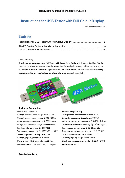
Instructions for USB Tester with Full Colour Display-Model: UM24/UM24CContentsInstructions for USB Tester with Full Colour Display .................................................... - 1 -The PC Control Software Installation Instruction...................................................................- 5 - UM24C Android APP Instruction ........................................................................................... - 16 -Dear Customer,Thank you for purchasing this Full Colour USB Tester from Ruideng Technology Co. Ltd. Prior to using this product we recommended that you briefly familiarize yourself with these instructions in In order to ensure the correct operation and use of the device. We also advise that you keep these instructions in a safe place for future reference as may be needed.Technical Parameters:Model: UM24 /UM24C Product weight:20.75gVoltage measurement range: 4.50-24.00V Voltage measurement resolution: 0.01V Current measurement range: 0.000-3.000A Current measurement resolution: 0.001A Capacity accumulation range: 0-99999mAh Voltage measurement accuracy: ± (0.2% + 1digit) Energy accumulation range: 0-99999mWh Current measurement accuracy: ±(0.8%+3 digits) Load impedance range: 1.5-9999.9ΩTime measurement range: 0-99h59min59s Temperature range: -10℃~100℃/0℉~200℉Temperature measurement error: ± 3℃/ ± 6℉Screen brightness setting: Levels 0-5 Auto screen off time: 1-9 minutesVoltage graphing range: 04.5-24.0V Current graphing range: 0.00A-3.00A Dimensions:71.2mmx31.8mmx11.3mm Quick charge recognition mode:QC2.0 QC3.0 Display screen:1.44 Inch color LCD display Refresh rate: 2HzFunction InterfacesMeasurement MainInterface Quick Charge Recognition Interface Data Recording InterfaceData Connection CableImpedanceMeasurement InterfaceVoltage GraphingInterface Current GraphinginterfaceSettings InterfaceDevice Layout1: Multifunction buttons (4) 2: Micro USB Port 3: USB A Male Port 4: USB A Female Port5: 1.44 Inch Color LCD Screen6: Bluetooth Indicator Light: When connected to the host computer control software, theBluetooth indicator changes from flashing to steady state. When connecting, the Bluetooth icon is displayed on the screen. (Bluetooth communication version only).Operating InstructionsWhen the unit is first powered on the welcome screen is displayed followed shortly by the main interface screen.Hidden interface: Pressing any buttonwhilst powering on the module will displaythree options. Option 1 selects the ChineseInterface and option 2 selects the Englishinterface.The third option is to zero the Currentreading (Ensure there is no load connectedto the unit). Holding the button will stepthrough the 3 options. Release the button at the desired selection. Pressing and holding the button after stepping to the third option will exit the hidden interface.Interface 1: Main MeasurmentInterface.1: Voltage measurement.2: Current measurement.3: Accumulated Capacity.4: Accumulated Energy.5: Temperature.6: Number of the Data Group in use.7: Load equivalent impedance.8: Power measurement.Press the "Help" button to enter the interface as shown above:Press and hold the "Next" button to switch Data Group. The USB tester can provide a total of 10 groups of data to save and view. These are numbered 0-9.With Data Groups 1-9 selected the current mAh and mWh are saved after power off. They will continue accumulating the next time the tester is powered on. When the data group selected is 0 then the current value of mAh and mWh will be temporarily saved at power off. When the device is next powered on these values will be recalled and will begin flashing. When the accumulated mAh exceeds 1 mAh, the previous data will be cleared and accumulation will restart.With a Data Group selected, press and hold the "Help" button to clear the mAh and mWh. Press "Next" to switch to the Quick Charge Recognition Interface.Interface 2: Quick Charge Recognition Interface.9: D +: (DP) data positive signal level.10: D-: (DM), data negative signal level.11: Mode display: The product willautomatically identify a device with asupported fast charging mode. At thistime the device supports the QC2.0 andQC3.0 mode only.Press "Next" to switch to the Data Recording InterfaceInterface 3: Data Recording Interface12: Time display: The total accumulated recording time.13: Low Current trigger value.REC: recording status indicator. ‘REC’ displayed in red indicates that recording is stopped. ‘REC’ displayed in green indicates that recording is in progress.After power on, when the current flowing is greater than the Low Current trigger value. The system automatically begins to record the accumulated capacity, energy, and time elapsed. The ‘REC’ indicator will change from red to green.To set the Low Current trigger value, press and hold the "Next" button to highlight the value then press the ‘Next’ button to adjust the value as required. The value can be set anywhere between 0.01A- and 0.30A. (10mA to 300mA).Press "Next" button to switch to the Data Connection Cable impedance Measurement Interface.Interface 4: Data Connection Cable Impedance Measurement Interface.The Tester can be used to measure theresistance of a data connection cable.14: 1. USB Tester directly connected to thepower supply with Voltage and Currentvalues displayed.15: B Tester connected via a dataconnection cable with Voltage and Currentvalues displayed.16: R: Data Connection Cable resistance.Measurement procedure:First, connect the USB Tester directly to the power supply and adjust the appropriate load current (recommended value 1A). Press and hold the "Next" button to begin recording data. The indicator prompt will stop flashing.Second,unplug the USB Tester and then reconnect it to the power supply via the data connection cable and adjust the load current to the same value as in the first step. Press and hold the "Next" button to begin recording data. The indicator prompt stops flashing and the Data Connection Cable resistance measurement test is completed and the value displayed.Note: If during the second step the screen turns black, this indicates that the voltage difference is too high and the tester will enter the 4.5V power-down state. The load current needs to be reduced. Then re-start the measurement from the first step. After the Data Connection Cable resistance test is completed, the Tester needs to be powered off and then on again to resume measurement.Press the "Next" button to switch to the voltage graphing interface.Interface 5: Voltage Graphing Interface.This interface displays the voltagemeasurement over time in the 4.5V-24.0Vrange and will automatically adjust thedisplayed range in real time to account for voltage fluctuations.Press the "Next" button to switch to the Current graphing interface.Interface 6: Current graphing Interface.This interface displays the Currentmeasurement over time in the 0.00A-3.00Arange and will automatically adjust thedisplayed range in real-time to account forCurrent fluctuations.Press the "Next" button to switch to theSettings interface:Interface 7: Settings Interface.17: Auto screen off time18: Screen brightness19: Temperature display C /FPress and hold the "Next" button to stepthrough the options of auto screen off time,brightness level and temperature display units. Stop on the value you wish to change then press the "Next" button to change the setting. For auto screen off time setting press ‘Next’ to repeatedly step though the 10 options from 0 to 9 minutes. For the screen brightness setting, press ‘Next’ to repeatedly step though the 6 options from 0 to 5 where 0 is the lowest brightness level and 5 is the highest. For the temperature display units, pressing the ‘Next’ button toggles the setting between C and F. To exit the Settings menu press and hold the ‘Next’ button.The PC Control Software Installation InstructionNote: This product only supports Windows 7 and above.1 Unzip the installation packageNote: Before unzip the installation package , please install the font package “ArialUnicode MS.ttf ”.2 Click setup to install3 Bluetooth connection3.1 View device Manager3.2 Connect bluetooth:3.2.1 Bluetooth connection is successful; there will be two serial ports. Select the lower value port. Example, if the ports configured for Bluetooth are COM3 and COM4, then select COM3 for the connection. Or you right click bluetooth device to see the the attribute, there show the corresponding port number. You can select it.3.2.2 When the Bluetooth indicator changes from blinking to static, click “Connect”4. Function Introduction4.1 Program interface overview:1: Basic functions: Rotate screen, Next pages2: Corresponding data group: data group switch, data group data clear3: Corresponding the main display interface 1: main measurement interface4: Corresponding the main display interface 3: Data recording interface5: Corresponding the main display interface 2: Quick Charge Recognition interface6: Corresponding the main display interface 7: Settings interface, dual format temperature display7: Corresponding the main display interface 7: Settings interface, screen brightness, auto screen off time.8: Corresponding the main display interface 6: Current Graphing Interface.9: Corresponding the main display interface 5: Voltage Graphing Interface.4.2 Graphing and Data Export:Move mouse over the Voltage / Time measurement graph then right-click and select the following options:4.2.1: Copy data to the clipboard:4.2.2: Automatically adjust the X axis:4.2.3: Export data to the clipboard:Format : Reference point number on X Axis, Voltage value at that reference point.Read times - Voltage graph Voltage(V) - Voltage graph0 12.031 12.022 12.033 12.034 11.975 12.006 12.007 12.088 12.109 12.13…4.2.4: Export data to Excel:Export data to Excel. If you want export all data, remember to click auto scale X. otherwise only the current record data group is exported. Please note, the exported data is only for Microsoft Office Excel.4.2.5: Export simplified images:4.2.6: Clear chart:Note:1. for desktop, when you use the bluetooth adapter to make bluetooth connection, Please don’t use the adapter own driver, and use the windows system bluetooth driver, otherwise the module can’t make SSP series port communication. If you have installed the adaptor driver, you can uninstall it and unplug the adaptor, then plug in again, the system will install it automatically.2. after power off, when power on again, you need to select the COM port again. When the bluetooth indicator is lighting, you can connect the PC with module3, please use windows official version, simple version may lose some part.4, when communicating, don’t press the button on tester, otherwise there will be some error data5. The exported data is only for Microsoft Office Excel.UM24C Android APP Instruction1, APP Installation:NOTE:The APP only support Android 5.0 and above.UM24C Android APP download link:/folder/0jt6xx2cyn7jt/UM241.1 APP download link : /folder/0jt6xx2cyn7jt/UM24 , choose UM24C android APP file to download, you can use the computer to download , then sent the phone, or use the phone download directly.1.2 Open the installation packageA BC D2. After Installation APP icon as the picture2.1 Click APP icon, the interface as the following:1: Export data to the mobile phone folder(phone SD card root director, repeat to write, generate graph directly in the excel.)2: Multiple language choice, click this to select language. For now there are 17 kinds language( 简体中文繁體中文English русский Español Deutsch Français 日本語한국어हहहहहह हहह Bahasa Indonesia Hollands Polski Slovenskýjazyk latviešu valoda Türkçe), More languages continue to be updated.3: Bluetooth connection: click this to select the device, search this device bluetooth name, select it and enter pair code (0000 or 1234), click connection (if you can’t search UM24C bluetooth name, you can connect the bluetooth on the phone bluetooth, then open APP to connect directly)4: Procedural information the version number, the assist personnel information5:Voltage-current measurement dual graph6:Corresponding the main display interface 3: accumulated mAh, accumulated mWh.7:Corresponding the main display interface 2: quick charge recognition, D+ D- data signal wire voltage8:Corresponding the main display interface 7:Screen brightness adjustment: press and hold the slider to adjust.Off the screen time adjustment: press and hold the slider to adjustTemperature display: Celsius/ Fahrenheit9:Switch to next page10:clearing key:clear current data group to zero11:Switch data group: click data group to choose one of 0-9 total 10 gourps12:Rotation button: control USB tester display to rotate13:Corresponding the main display interface 4, mAh and mWh display , time recording, control the slider to adjust the Low Current trigger value.14:Corresponding the main display interface 1, voltage measurement value, current measurement value, power measurement value, load equivalent load impedanceNoteA:Because there are too many kinds android phone, so the UI display interface will be different at some brand phone or different scale screen of one brand phoneB:Application access requirements, allowing the necessary permissions when installing (allows the background running, allows to use bluetooth, allowing folder operation, allowed to read the application list); and also set application permissions at phone after installation: allows the background running , allow to be not cleaned after screen locked, allow auto-start and so onC:Languages selection memory, only at first time you need to select the language when open APP.。
USB触摸屏说明书
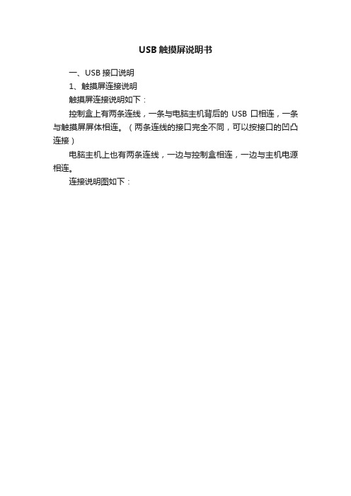
USB触摸屏说明书一、USB接口说明1、触摸屏连接说明触摸屏连接说明如下:控制盒上有两条连线,一条与电脑主机背后的USB口相连,一条与触摸屏屏体相连。
(两条连线的接口完全不同,可以按接口的凹凸连接)电脑主机上也有两条连线,一边与控制盒相连,一边与主机电源相连。
连接说明图如下:2、驱动程序安装说明1)、安装驱动程序:A:首先,打开电脑,把连接线的USB口和取电口插入电脑,另一端接控制盒,接好后系统认到新设备并自动安装USB设备的驱动,如下所示:B:USB设备的驱动装好后就可以安装触摸屏的驱动程序,双击触摸屏驱动盘中的Setup.exe,开始安装C:点击“下一步”按钮,出现以下画面:D:点击“完成”,会弹出“没有找到数字签名”窗口,点“是”继续安装E:通过数字签名后,驱动完成安装,并弹出控制面板F:点击面板中的“校准”按钮,出现校位画面,请用手点击画面的圆圈以进行校准。
图面如下:G:按“是”保存校准的坐标退出,如果不准可按“否”重新校准。
2)、驱动程序控制面板参数设置:点击开始控制面板,双击打开“ETWOTouch设置程序”图标屏幕校准点击“校准”按钮,重新校准触摸屏。
声音设置触摸屏有三种发声模式:“从不”是指关闭触摸声音;“刚触摸时”为触摸时发出声音,“离开时”为手指从触摸屏移开时发出声音。
声音设置鼠标模式“触摸时点击”为刚触摸屏体时响应;“离开时点击”为手指从屏体移开时响应;“拖动”功能同“触摸时点击”,但可以在屏体上拖动;“拖动、双击”功能同“拖动”,但加大了双击的有效范围使双击变为更容易。
3)、卸载驱动程序:A :点击开始程序 ETWOTOUCH Uninst 出现以下窗口:B :点击“完成”,触摸屏驱动程序卸载完成。
设置双击的有效范围设置双击的间隔时间二、使用注意事项1、使用注意事项:a、硬件部分工作正常情况下,开机时控制盒指示灯短暂长亮(约二、三秒钟)后熄灭,点击触摸屏时指示灯亮,手指离开后,指示灯熄灭。
综合测试仪设备操作说明书
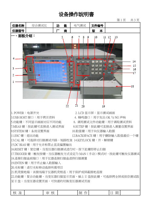
仪器名称 综合测试仪功 能 电气测试文件编号仪器型号厂 商版 本 一、面板介绍:1. POWER :电源开关2. LCD 显示屏:显示测试画面B HOST 接口:用于拷贝资料4. 蜂鸣器口:用于发出OK 与NG 声响5.功能键:不同显示画面对应不同功能6. 调用测试文件功能键:用于调取测试资料7.MEAS 键:按此键可直接进入测试界面8.SUTEP 键:按此键可直接进入测量设置界面9.SYSTEM 键:系统设置界面 10.数值键:用于向仪器输入数据11.ESC 键:退出功能 12.BACKSPACE 键:用于删除输入数值最后一个键 13.CAL 键:可选择对扫描测试开路、短路校准 14.KEYLOCK 键:开、解锁键 15.DC BIAS 键:用于允许和禁止直流偏置输出16.RESET 键:复位键,当变压器扫描测试进行时,按下此键即停止扫描17.TRIGGER 键:触发按键,当仪器触发方式设定为MAN (手动)模式时,按此键可触发仪器测试 18.连接扫描盒前端口:用于仪器连接扫描盒进持扫描测量 19.ENTEN 键:用于终止输入数据输入 20.光标键:进行光标移动选择所需项目21.机壳接地端:该接线端于仪器机壳相连。
用于保护或屏蔽接地连接22.功能键:复合功能键。
当变压器扫描显示页面,插上U 盘按此键,可选择拷全屏或保存测试数至U 盘;当变压器设置页面,可快速的切换变压器测试页面核 准 审 核 制 作 日 期4321567 8 910110 120130140 150 160 170 18192021 22仪器名称 综合测试仪功 能 电气测试文件编号 仪器型号厂 商版 本二、操作说明:1.仪器、扫描盒、治具的连接如下图:23.连接扫描盒前端口:用于扫描盒连接仪器 24.扫描盒:由仪器控制其扫描测量 25.脚踏板开关: 26.综合测试治具27.SCANNER :控制端口,用专用电缆线将扫描盒SCANNER 接口与仪器SCANNER 接口相连接 28.专用电缆线:用于仪器与扫描盒的连接 29.电源线:用于接通220V/50HZ 的电压 30.SCANNER 接口:通过SCANNER 接口控制变压器扫描盒2.仪器的开机:接通220V/50HZ 电源后,按下如图“1”电源开关按键后再按MEAS 键进入变压器测试界面。
FMI-B30 数字精密测力计 (USB) 说明书
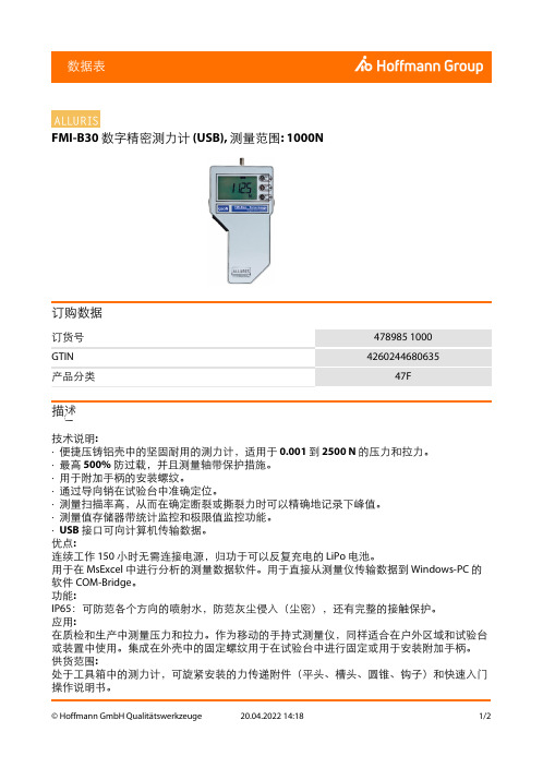
FMI-B30 数字精密测力计 (USB), 测量范围: 1000N订购数据描述技术说明:·便捷压铸铝壳中的坚固耐用的测力计,适用于 0.001 到 2500 N 的压力和拉力。
·最高 500% 防过载,并且测量轴带保护措施。
·用于附加手柄的安装螺纹。
·通过导向销在试验台中准确定位。
·测量扫描率高,从而在确定断裂或撕裂力时可以精确地记录下峰值。
·测量值存储器带统计监控和极限值监控功能。
·USB 接口可向计算机传输数据。
优点:连续工作 150 小时无需连接电源,归功于可以反复充电的 LiPo 电池。
用于在 MsExcel 中进行分析的测量数据软件。
用于直接从测量仪传输数据到 Windows-PC 的软件 COM-Bridge。
功能:IP65:可防范各个方向的喷射水,防范灰尘侵入(尘密),还有完整的接触保护。
应用:在质检和生产中测量压力和拉力。
作为移动的手持式测量仪,同样适合在户外区域和试验台或装置中使用。
集成在外壳中的固定螺纹用于在试验台中进行固定或用于安装附加手柄。
供货范围:处于工具箱中的测力计,可旋紧安装的力传递附件(平头、槽头、圆锥、钩子)和快速入门操作说明书。
软件 FMI-Connect。
校准: 价格承索IP 保护等级: IP 65分辨率: 0.2 N误差范围: ±0.15 最大值(±1 数字的) %连接螺纹: M6长度: 150 mm宽度: 82 mm高度: 29 mm技术说明。
- 1、下载文档前请自行甄别文档内容的完整性,平台不提供额外的编辑、内容补充、找答案等附加服务。
- 2、"仅部分预览"的文档,不可在线预览部分如存在完整性等问题,可反馈申请退款(可完整预览的文档不适用该条件!)。
- 3、如文档侵犯您的权益,请联系客服反馈,我们会尽快为您处理(人工客服工作时间:9:00-18:30)。
USB彩屏版测试仪使用说明型号:UM34/UM34C修订时间2019-8-3尊敬的用户,感谢您购买由睿登科技有限公司出品的USB彩屏版测试仪,为了让您更快了解本产品的全部功能,获得更好的使用体验,避免出现误操作,使用前请仔细阅读本说明并保留好,以便日后查阅。
目录USB彩屏版测试仪使用说明 (1)1.1产品技术指标 (4)1.2功能界面 (4)1.3核心功能 (4)1.4面板说明 (5)1.5界面提示符代表功能 (5)1.6操作说明 (5)1.6.1测量主界面 (6)1.6.2快充识别界面 (6)1.6.3充电记录界面 (7)1.6.4线阻测量界面 (7)1.6.5测量曲线界面 (7)1.6.6系统参数设置界面 (8)UM34C安卓手机APP使用说明书 (9)2.1手机APP软件安装 (9)2.1.1APP的下载 (9)2.1.2APP的安装 (9)2.2安装完成 (10)2.2.1APP的使用 (10)2.2.2APP界面显示 (10)UM34C苹果手机APP使用说明 (13)3.1APP使用方法 (13)3.2APP更新 (13)附录1:名词解释 (13)附录2:基本操作知识 (14)1.1产品技术指标型号:UM34/UM34C 显示屏幕:1.44寸彩色液晶显示屏输入电压:4-24.00V电压测量分辨率:0.01V 输入电流:0-4.000A电流测量分辨率:0.001A 容量测量范围:0-99999mAh电压测量精度:±(0.2%+1个字)能量测量范围:0-99999mWh-999.99Wh电流测量精度:±(0.8%+3个字)负载阻抗测量范围:0.8Ω-9999.9Ω时间测量范围:0-99小时59分钟59秒温度测量范围:-10℃~100℃/0℉~200℉温度测量误差:±3℃/±6℉屏幕亮度设置:0-5共6级延时关屏时间:0-9分钟(0为长亮)电压曲线范围:4-24.00V 电流曲线范围:0-4.000A含包装重量:约52g(UM34C)/47g (UM34)数据刷新率:2Hz产品尺寸:71.2mmx30.5mmx12.4mm(UM34C)/71.2mmx30.5mmx11.3mm(UM34)快充识别模式:QC2.0、QC3.0、APPLE 2.4A/2.1A/1A/0.5A 、Android DCP 、SAMSUNG (注:此快充协议识别模式仅供参考,手机更新换代较快,无法百分百准确识别)USB 接口:USB3.0接口,支持OPPO 手机VOOC 闪充(不支持Super VOOC),一加手机DASH 快充。
1.2功能界面测量主界面快充识别界面充电记录界面线阻测量界面测量曲线界面系统参数设置界面1.3核心功能USB3.0接口快充模式识别手机APP控制自带中英文帮助界面数据记录、存储及导出容量/能量检测压差法测量线阻阻值负载接入检测功能,插上负载,自动点亮屏幕输入电压电流及功率检测屏幕可四向旋转1.4面板说明A:Micro USB接口B:多功能按键(共4个)C:蓝牙电源开关D:USB3.0母座接口E:USB3.0公头接口F:Type-C输入接口(仅测量USB转Type-C线内阻用)G:1.44寸彩色液晶显示屏H:蓝牙指示灯:蓝牙连接后,蓝牙指示灯由闪烁变为长亮;连机后,屏幕显示蓝牙标志(仅限UM34C,USB3.0通信与蓝牙会有同频干扰现象存在,通信时请关闭蓝牙)。
1.5界面提示符代表功能I:长按对应按键实现逆时针旋转画面J:短按对应按键实现关屏K:短按对应按键出现帮助界面L:长按对应按键实现顺时针旋转画面M:短按对应按键翻到上一页N:短按对应按键翻到下一页1.6操作说明隐藏界面:按住任意按键再给测试仪通电会显示四个选项,第一项为设置中文语言,第二项为设置英文语言,第三项为恢复出厂设置(重置后设置参数恢复,存储的数据不受影响),第四项为电流零点校准(执行该项功能时,须保证无欢迎界面隐藏界面负载接入)。
按键不松开会依次选中四项,在选中项处松开按键表示执行该项设置,若第四项过后仍未松开按键,表示不执行任何功能,将退出隐藏选项界面。
上电后首先显示欢迎界面,然后进入主界面。
1.6.1测量主界面O:电压测量值P:电流测量值Q:累计容量值R:累计能量值S:温度测量值T:数据组编号U:负载等效阻抗V:功率测量值短按“帮助”键,界面显示如上图。
长按“下一页”键切换数据组,本测试仪可提供0-9共10组数据的保存和查看。
当数据组为第1-9组时,掉电时存储当前容量和能量,待下次开机继续累加。
当数据组为第0组时,掉电时暂存当前容量和能量,待下次开机时闪烁提醒上次容量和能量,当累加容量超过1mAh自动清除上次数据,重新开始累计。
在数据组编号选中状态下,长按“上一页”键可清零本组数据组内累计容量值和累计能量值。
如图:短按“下一页”键切换到快充识别界面:1.6.2快充识别界面W:D+,DP,数据正信号X:D-,DM,数据负信号Y:模式显示该产品会自动识别快充模式,本产品能识别QC2.0、QC3.0、APPLE2.4A/2.1A/1A/0.5A、Android DCP、SAMSUNG等快充协议。
(注:D+D电压和快充协议识别模式仅供参考)短按“下一页”键切换到充电记录界面。
1.6.3充电记录界面Z :累计容量值AA :累计能量值AB :记录时间:当前负载累计记录时间AC :截止电流AD :REC :记录状态指示,红色REC 代表停止,绿色REC 代表记录中。
通电后,当电流大于截止电流时,系统开始记录容量和能量,时间随之增加,且REC 由红色变为绿色。
长按“下一页”键选中截止电流,短按“上一页”依次循环调整数值,本产品截止电流可以在0.01-0.30A 之间进行设置,长按“下一页”键取消编辑状态。
短按“下一页”键切换到线阻测量界面。
1.6.4线阻测量界面AE :测试仪直接接入电源时电压电流值AF :测试仪通过待测数据线接入电源时电压电流值AG :R ,数据线线阻本产品此界面可通过压差法来测量数据线的线阻值,操作步骤:第一步:测试仪直接接入电源,调节合适负载电流(建议1A ),长按“下一页”键记录数据,右侧指示图标停止闪烁。
第二步:拔掉测试仪,将测试仪通过Micro USB/Type-C IN 数据线接入电源,负载电流调节至第一步相同电流,长按“下一页”键记录数据,右侧指示图标停止闪烁,线阻测试完成,显示数据线线阻值。
注意事项:若第二步插入数据线后测试仪屏幕变黑,表明压差太大,测试仪进入4.0V 掉电状态,需减小负载电流,重新从第一步开始测量。
线阻测量完成后,在测试仪下次上电后重新开始测量。
短按“下一页”键切换到测量曲线界面。
1.6.5测量曲线界面此界面为电压-电流测量波形图,电压在4.00-24.00V 测量范围内自动变换量程,实时显示电压波动情况。
电流在0-4.000A测量范围内自动变换量程,实时显示电流波动情况。
长按“下一页”键进入D+D-曲线图,如图:此界面为D+-D-测量波形图,D+/D-电压分别在0-3.3V 测量范围内自动变换量程,分别实时显示D+/D-电压波动情况。
短按“下一页”键切换到系统参数设置界面。
1.6.6系统参数设置界面AH :延时关屏时间设置AI :屏幕亮度设置AJ :温度单位切换设置AK :主题背景色设置AL :主题前景色设置长按“下一页”键进入设置状态,对应位置对应数字选中并反显,短按“下一页”键可依次循环设置延时关屏时间、亮度等级、温度单位切换、主题背景色设置、主题前景色设置。
在设置状态下:默认状态为关屏时间设置,对应数字选中并反显,短按“上一页”键可以循环修改数值,数值在0-9共10个数值之间进行依次循环改变,其中0为长亮。
默认关屏时间为1分钟。
短按“下一页”键进入屏幕亮度设置,对应数字选中并反显,短按“上一页”键可改变数字大小,数字越大,屏幕越亮,共6级设置。
默认亮度等级为4。
短按“下一页”键进入温度单位切换,对应数字选中并反显,短按“上一页”键可以在0和1之间切换,0为摄氏度,1为华氏度。
默认温度单位:摄氏度。
短按“下一页”键进入主题背景色设置,对应数字选中并反显,短按“上一页”键可以在0-7之间切换,颜色按照“红色、绿色、蓝色、黄色、浅蓝色、粉红色、白色、黑色”的顺序依次进行切换。
默认主题背景色:蓝色。
短按“下一页”键进入主题前景色设置,对应数字选中并反显,短按“上一页”键可以在0-7之间切换,颜色按照“红色、绿色、蓝色、黄色、浅蓝色、粉红色、白色、黑色”的顺序依次进行切换。
默认主题前景色:白色。
任意参数设置状态下,长按“下一页”键退出设置状态。
电压电流曲线D+D-信号曲线UM34C安卓手机APP使用说明书2.1手机APP软件安装注:本产品手机APP功能仅支持Android5.0及以上系统使用。
UM34C安卓APP下载链接:https:///s/19ho51-wLye3xtZgYvSlpmg2.1.1APP的下载APP安装下载地址:https:///s/19ho51-wLye3xtZgYvSlpmg,选择APK 文件,电脑下载通过QQ发送到手机或者直接手机打开链接将安装包下载到手机中(如不会下载或无法下载可以找客服人员索取该软件)。
2.1.2APP的安装打开手机文件,找到APP安装包,安装过程如下图:(1)(2)(3)(4)2.2安装完成安装完成,手机APP图标如下:2.2.1APP的使用点击APP图标,APP启动后,系统会自动后台检测APP版本是否有更新,新版本会弹框提醒更新,界面显示如下:2.2.2APP界面显示更新完成后,APP主界面显示如下图(1):图(1)图(2)AM:导出数据到手机文件夹(手机内存或者SD卡根目录,重复写入,在Excel 中能直接生成曲线图),同时可以将文件分享到其他APP查看(如图2)AN:多语言选项,点击可选择语种,目前22种语言(汉语(简/繁),英语,俄语,波兰语,西班牙语,印地语,斯洛伐克语,拉脱维亚语,日语,德国语,荷兰语,韩语,法语,土耳语,泰语,印尼语,捷克语,乌克兰语,希腊语,匈牙利语,葡萄牙语…),更多语言持续更新中。
AO:蓝牙连接:点击进入设备选择,搜索本设备蓝牙名称,输入配对码1234点击连接(首次连接,先在手机设置蓝牙进行配对连接,然后打开APP点击蓝牙图标后连接。
)AP:程序信息:版本号说明、协助开发人员信息AQ:电压-电流测量双曲线AR:(同O)电压测量值AS:(同P)电流测量值AT:(同V)功率测量值AU:(同U)负载等效阻抗AV:毫安时记录AW:毫瓦时记录AX:(同AB)记录时间AY:(同AC)截止电流AZ:(同T)数据组编号(点击下拉三角形即可切换数据组)BA:(同Q)累计容量值BC:(同R)累计能量值BD:(同Y)快充模式识别BE:(同W)D+数据信号线电压BF:(同X)D-数据信号线电压BG:(同AI)屏幕亮度调整:按住滑动条即可实现BH:(同AH)关屏时间调整:按住滑动条即可实现BI:(同AJ)温度显示(摄氏度/华氏度)BJ:切换至上一页BK:翻转键:控制USB测试仪屏幕翻转BL:清除键:当前数据组清零BM:切换至下一页注:1:因安卓手机种类繁多,因此在个别品牌或者一种品牌的不同比例屏幕上UI界面显示不一样。
