CMS监控系统说明书-中文
网络视频集中管理软件(CMS)使用说明书
在权限控制下,用户可以通过系统客户端对每个监控点方便地进行控制和设置,系统还集成了电 子地图功能。
1.2.11 集成度高。
系统集成了其它相关信息,如报警信息、语音信息等。 1.2.12 可靠性高。
第五章 系统设置........................................................................................................................... 16 5.1 监控点设置 .......................................................................................................................... 16 5.2 客户端配置 .......................................................................................................................... 20 5.3 设备配置 .............................................................................................................................. 24 5.4 用户管理 .............................................................................................................................. 36 5.5 客户端日志 .......................................................................................................................... 37
CMS产品说明书

CMS产品说明书1.概述网站内容管理系统(Content Management System,简称CMS)是搜狐公司对搜狐网站和其他企业网站建设的需求进行长期深入分析,并结合成功实施这些网站建设项目的实践经验,而推出的专门面向互联网站内容编辑与发布的应用系统。
开发这套CMS系统旨在利用搜狐公司管理庞大的后台信息系统的经验,帮助政府机关和企事业单位规范其网站后台信息流程、统一数据存储格式、减少网站维护的投入、加强信息披露的权限管理。
它的出现将大大减轻建立各类信息网站的复杂性,并使网站的运营管理、内容维护变得易如反掌。
CMS基本信息流程如下所示:2.功能简介2.1.栏目管理用于管理栏目,具体的功能有:栏目的增加、修改、删除,以及查询栏目的基本信息。
整个站点的栏目呈树状结构,栏目的级数可以任意添加。
2.2.合作伙伴管理用于管理合作伙伴(稿件来源),具体的功能有:合作伙伴的增加、修改、删除,以及查询合作伙伴的基本信息。
对于只发布自己内容的网站,此项功能无需使用。
2.3.标记管理用于管理预定义标记,具体的功能有:页面的预定义标记的增加、修改、删除。
标记是网站编辑人员镶嵌在模版中的特定标识,标记管理中对这些标记作出说明,在生成页面时用于替换这些标记。
2.4.模板的处理在数据库中保存的内容在生成页面的过程中依赖于不同频道的模板以形成不同的页面。
模板的基本样式由编辑确定,技术人员会根据这些页面抽取有效内容形成模板。
在页面发生变动时,有经验的编辑或技术人员可以修改模板。
模板保存在数据库中,用以统一每个栏目的观感(Look & Feel)。
模板将尽可能地使用公用的框架,减少对资源的占用。
以搜狐页面为例说明模式如下:文章页面二级索引页面其中使用的模块说明如下:●Sohu:搜狐的图形标志●频道:频道的图形标志●广告:旗帜广告●搜狐导航条:所有搜狐页面上统一的频道列表●频道导航条:频道内所有页面统一的热门链接(栏目、频道)●栏目菜单:频道内所有栏目的链接列表;●合作伙伴菜单:频道内所有合作伙伴的链接列表;●相关分类:与频道相关的搜狐分类的信息;●文章:文章的内容,包括标题、正文、发布时间等。
CMS操作说明.

视频集中监控管理系统使用说明书上海睿网电子有限公司Shanghai Ruinet Electronics Co., Ltd 一、软件的打开与登录(1)双击击桌面图标“CMS视频集中监控管理系统”启动应用程序。
(2)软件打开后,进入平台登录主界面。
用户名和密码对于不同级别权限的用户有不同账户IP地址或域名:此处填写权限管理服务器的端口地址输入自己的用户名和密码登录软件二、画面组的切换与球机控制(1)画面的组切换单击换组,选择想要查看的组,即可切换到预先配置好的各个图像组已经切换好的图像组鼠标右键弹出的菜单栏中,可以对软件主界面的画面数进行调整。
可以单击画面宫格,在宫格边框变红的状态下再双击摄像机地址栏中的画面查看当前选择的摄像机的图像可以直接拖动摄像机地址栏中的摄像机到相应的宫格画面,当前拖动的摄像机画面会直接显示在目标宫格上(2)球机的控制双击单个画面放大,如果是球机提供的画面,可以在软件控制栏中对画面的图像进行位置和焦距的调整。
其控制按钮如上图所示。
也可以在视频画面中按照鼠标的指示箭头方向移动画面,还可以通过滚动鼠标滚轮对画面的焦距进行调整。
三、视频网络回放功能的使用(1)视频回放单机回放按钮,选择网络回放。
软件自动切换到回放界面单击下拉菜单按钮,选择相应回放存储服务器单击所有记录按钮的下拉菜单,选择需要回放视频的日期再选择相应回放视频摄像头的视频通道,通道选择完毕后会出现对应视频的时间段。
双击某某时间段,播放对应时间段的视频。
视频播放界面可以拖动进度条,对视频进行快速定位。
也可以在选定的监看画面反点右键,对本画面进行回放。
支持矩阵屏幕墙上回放录像。
注意:视频回放功能是需要有回放查看权限的账号登录才可以回放,普通操作者账号是无权对视频进行回放的。
在本机上控制大屏图像的操作:在主界面鼠标右键里,选择“视频VGA矩阵”如下图进入VGA矩阵界面后,右键在画面数里选择4画面,大屏就变成四画面,如下图:点选通道窗口后,可把右边树列表里的摄像机拖进矩阵里,大屏的图像就会出来。
CMS网络摄像头客服端使用说明书
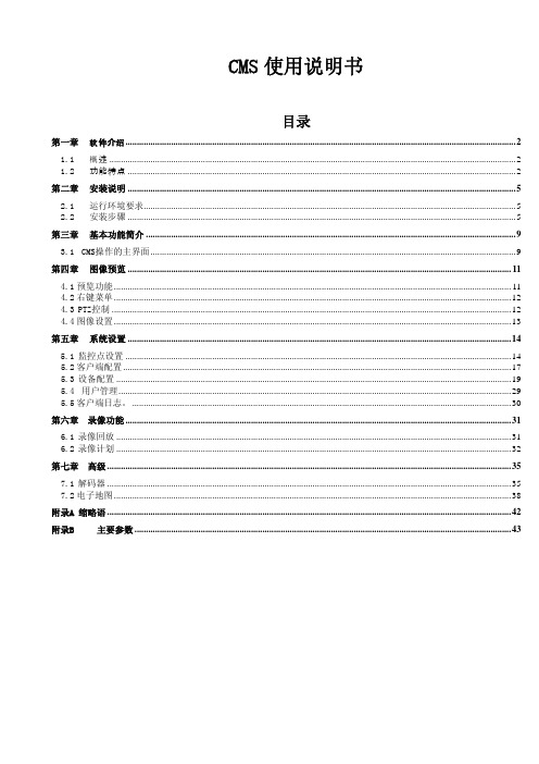
第六章 录像功能 .........................................................................................................................................................................31 6.1 录像回放 .............................................................................................................................................................................31 6.2 录像计划 .............................................................................................................................................................................32
CMS组态软件使用说明书
CMS 组态软件使用说明书
CMS 组态软件使用说明书 (Version 2.0)
湖北万洲电气集团有限公司
HUBEI WORLDWIDE ELECTRIC GROUP CO., LTD.
湖北万洲电气集团有限公司 湖北省襄阳市长征路 58 号 邮编:441001 电话:(0710)3405668
用户将程序安装完毕后,进入安装的目标文件夹,如 D:\CMS。可以看到如下图所列文件。 湖北万洲电气集团有限公司 湖北省襄阳市长征路 58 号 邮编:441001 电话:(0710)3405668
-3-
万洲电气
CMS 组态软件使用说明书
图 1.4 CMS 软件组成
主要文件说明如下: CMSHelp:帮助文件夹,CMS 软件的操作和说明文件放在 CMSHelp 文件夹中,说明文件为.html 格式,用户可直接进入 CMSHelp 文件夹中点击打开或在程序中的帮助菜单进入。 CMSlockMenu:安全管理文件夹,文件夹中存放系统锁定后允许运行的程序快捷菜单。 CMSUILibrary:图形库文件夹,编辑好的图形库放在该文件夹。 DBRealTime:数据库文件夹,运行数据存储在该文件夹。 PlugIn:插件文件夹,CMS 扩展的插件模块放在该文件夹。 Protocols:通讯协议文件夹,监控软件所使用的通讯协议模块放在该文件夹。 CMS.exe:主监控程序。 CMSLock.exe:系统锁定程序,该程序运行后,将接管系统操作桌面,不能运行无关程序。 CMSReport.exe:报表程序,用于报表的设计和编辑。 CMSUser.exe:用户管理程序,用于管理操作用户的管理和操作权限。 Index.cmsui:画面程序,用于存放设计编辑的监控画面。 CurveView.exe:录波分析软件,可将录波数据和报表数据以波形或曲线形式显示。 default.cmscfg:用于存放通讯配置。 SelectCurve.exe:录波选择软件,使用该软件选择录取的波形文件。 SpeechAlert.exe:语音报警程序,中文语音报警。 BeepStart.exe:声音报警程序,可使用计算机自带轰鸣器报警。 2.4. CMS 软件的运行 CMS 组态软件安装完毕后,在桌面建立快捷方式,可选择 CMS 组态软件文件点击运行,也 可以选择锁定系统并运行 CMS 全部模块。区别是点击后者同时锁定并接管操作系统,用户不能 运行其它无关程序。 湖北万洲电气集团有限公司 湖北省襄阳市长征路 58 号 邮编:441001 电话:(0710)3405668
CMS客户端操作说明书

CMS使用说明书目录第一章软件介绍1.1 概述本软件是一个功能强大的中控软件,分布式架构,集多窗口,多用户,多语言,语音对讲,视频会议,分级电子地图,报警中心,兼容其它扩展产品,单机直连设备监控系统等功能为一体。
软件具有电子地图功能,界面友好,操作简单,可方便的进行权限设置。
本软件是针对连接多台不同类型或型号的设备(如DVR,DVS等),此说明书只针对软件操作进行介绍,涉及到具体设备的功能设置请阅读相关的产品说明书。
本手册是为负责计划、执行或复查网络视频监控软件的硬件安装的任何人提供的。
您应具备相关设备(如DVR,DVS等)的基本操作知识和经验。
1.2 功能特点1.2.1用户及权限管理系统支持N级组织机构管理,及用户管理和权限设置管理。
1.2.2采用数据接口技术系统所有数据交互采用数据接口技术,可灵活支持各种大中小型数据库,如SQL、MYSQL及XML数据等。
1.2.3支持EXCEL表格编辑增加设备。
平台支持用户采用Excel表格软件进行设备的增加和编辑,方便用户进行大批量设备的维护,提高了系统的易用性和极大的减少了用户维护的工作量。
1.2.4智能视频传输协议。
使用智能视频传输协议,最大限度地利用网络带宽,特别对于前端网点网络带宽有限的情况下,系统在保证图像质量的基础上,在很低的网络带宽下,也能保证系统正常运行。
1.2.5可扩展的分布式网络结构。
支持多个服务器协调运行,智能负载均衡,在保证整体性的同时,可灵活增添服务器,有效提升系统处理能力1.2.6完善的视频监控功能。
在支持实时监视的同时,系统支持报警录像、自动监测录像、录像回放等,能精确控制各个通道的录像情况。
1.2.7动态调节解码缓冲。
实时监视时可灵活调节视频图像流畅性或实时性优先,流畅性讲求视频图像的流畅,实时性强调视频图像的实时,可满足不同用户的需求。
1.2.8采用货架技术,模块化开发,可灵活组装应用方案。
系统采用货架技术,分层及模块化开发,具有丰富的中件间服务,可以方便的进行各种应用方案的灵活组装。
监控系统操作说明书 通用
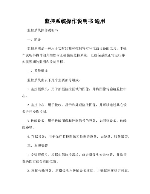
监控系统操作说明书通用监控系统操作说明书一、简介监控系统是一种用于实时监测和控制特定环境或设备的工具。
本操作说明书将详细介绍如何正确使用监控系统,以确保系统正常运行并实现预期的监测和控制目标。
二、系统组成监控系统由以下几个主要部分组成:1. 监控摄像头:用于拍摄监控区域的图像,并将图像传输给监控中心。
2. 监控中心:用于接收、显示和处理监控图像,并可以通过其它设备进行操作控制。
3. 传输设备:用于传输图像和控制信号的设备,如网络设备、传输线路等。
4. 存储设备:用于保存监控图像和数据的设备,如硬盘、服务器等。
三、系统安装1. 安装摄像头:根据实际监控需求,确定摄像头安装位置,并将摄像头固定在合适的位置。
2. 连接传输设备:将摄像头与传输设备连接,并确保连接稳定可靠。
3. 安装监控中心:根据实际需要,选择合适的监控中心设备,并将其安装在指定位置。
4. 连接传输设备和监控中心:使用合适的传输线路连接传输设备和监控中心,确保信号传输正常无误。
5. 配置和调试:按照监控系统提供的说明书进行系统配置和调试,确保系统正常工作。
四、系统操作1. 启动监控系统:按照监控中心设备的说明书,启动监控系统,并确保电源供应正常。
2. 查看监控图像:在监控中心的界面上,选择要查看的监控图像,系统将显示实时的监控画面。
3. 录像功能:根据需要,可以启动录像功能,将监控画面实时录制并保存在存储设备上,以便后续查看。
4. 控制操作:根据实际需要,可以使用监控中心设备提供的控制功能,如云台控制、放大缩小、镜头调节等。
5. 报警处理:监控系统可以设置报警功能,当监控画面中出现异常情况时,系统将发出警告信号,操作人员需要及时处理报警信息。
6. 数据分析:监控系统还提供数据分析功能,操作人员可以根据需要对监控数据进行统计分析和报表生成。
五、系统维护1. 定期检查:定期检查监控系统的各个部件是否正常运行,包括摄像头、传输设备、存储设备等。
CMS说明书

集中监控管理平台CMSVision操作说明目录1. 产品介绍 (2)1.1.概述 (2)1.2运行环境要求 (2)1.3安装与卸载 (3)2. 集中监控管理平台操作说明 (3)2.1.软件启动 (3)2.2.登录和退出系统 (3)2.3.添加设备 (4)2.4.主界面说明 (6)2.4.1.图像预览 (8)2.4.2.画面切换 (8)2.4.3.右键菜单 (9)2.5.云台 (10)2.6.图像管理 (11)2.7.系统设置 (11)2.7.1本地设置 (11)2.7.2远程配置 (13)2.7.3远程设备管理 (19)2.7.4电子地图 (20)2.7.5报警联动设置 (22)2.7.6报警输出设备 (25)2.8.录像功能 (25)2.8.1.开启和关闭录像 (25)2.8.2.远程回放 (27)2.8.3.本地回放 (28)2.8.4.录像计划 (29)2.8.5.设置集中录像 (30)2.8.6 强制切换录像文件 (32)2.9.高级 (34)2.9.1分组设置 (34)2.9.2分组切换 (35)2.9.3轮视 (35)2.9.4电视墙 (35)2.9.5语音对讲 (38)2.9.6日志管理 (41)2.9.7看图 (42)1. 产品介绍1.1.概述CMSVision是一款中型网络监控管理软件,采用分布式网络拓扑结构,支持流媒体转发和网络直接连接前端视频采集服务器:1、具有很强的扩展性,根据客户需求可以任意扩充监控点,一个监控点就是一个集中监控管理平台。
2、在用户访问控制方面,流媒体转发采用统一的用户访问控制,在流媒体服务器进行用户权限校验,直接连接前端视频采集服务器,在视频采集服务器端进行权限效验。
3、集中监控管理平台支持多画面图像预览和图像轮视,以及电子地图操作图像预览和联动报警功能。
4、在网络上采用当今最先进的完成埠技术,在相同的网络环境下比一般的TCP网络传输质量更高效,而且支持断线重连。
CMS X-Tools 用户手册 - 监控系统说明书

CMS X-ToolsUser Manual - 05 - Monitoring SystemEnglishRelease 2014-11Safety GuidelinesThis document contains notices which you should observe to ensure your own personal safety as well as to avoid property damage. The notices referring to your personal safety are highlighted in the manual by a safety alert symbol, notices referring to property damage onlyhave no safety alert symbolDanger Indicates an imminently hazardous situation which, if not avoided, will result in death or serious injury.Warning Indicates a potentially hazardous situation which, if not avoided, could result in death or serious injury.Caution Used with the safety alert symbol indicates a potentially hazardous situation which, if not avoided, may result in minor or moderate injury.NoticeUsed without the safety alert symbol indicates a potential situation which, if not avoided, may result in an undesirable result or state.When several danger levels apply, the notices of the highest level (lower number) are always displayed. If a notice refers to personal damages with the safety alert symbol, then another notice may be added warning of property damage. Qualified PersonnelThe device/system may only be set up and operated in conjunction with this documentation. Only qualified personnel should be allowed to install and work on the equipment. Qualified persons are defined as persons who are authorized to commission, to earth, and to tag cir-cuits, equipment and systems in accordance with established safety practices and standards. Intended UsePlease note the following:WarningThis device and its components may only be used for the applications described in the catalog or technical description, and only in connection with devices or components from other manufacturers approved or recommended by Siemens. This prod-uct can only function correctly and safely if it is transported, stored, set up and installed correctly, and operated and main-tained as recommended.TrademarksAll designations marked with ® are registered trademarks of Siemens AG. Other designations in this documentation might be trademarks which, if used by third parties for their purposes, might infringe upon the rights of the proprietors. Copyright Siemens AG 2014. All rights reserved.Reproduction, transmission or use of this document or its contents is not permitted without express written authority. Offenders will be liable for damages. All rights, including rights created by patent grant or registration of a utility model or design, are reserved. Disclaimer of LiabilityWe have checked the contents of this document for agreement with the hardware and software described. Since deviations cannot be precluded entirely, we cannot guarantee full agreement. However, the data in the manual are reviewed regularly, and any necessary cor-rections will be included in subsequent editions. Suggestions for improvement are welcomed.Siemens AG Industry Sector P.O. Box 4848 90327 Nuremberg GermanySiemens AG 2014Technical data subject to changeTable of Contents1Preface (17)1.1Purpose of this Document (17)1.2Validity of this Document (17)1.3Audience (17)1.4Notations (18)2Monitoring System (19)2.1Monitoring System Explorer (19)2.1.1Overview (19)2.1.2Main Branch (20)2.1.3Editors Branch (20)2.1.4Monitoring Charts Branch (20)2.1.5Monitoring Chart Branch (21)2.1.6Monitoring View Editors Branch (21)2.1.7Monitoring View Editor Branch (21)2.1.8Servers Branch (21)2.1.9Server Branch (21)2.1.10Files Branch (21)2.1.11File Location Branch (22)2.1.12Monitoring View Files Branch (22)2.1.13Libraries Branch (23)2.1.14Analyzing Functions Branch (23)2.1.15Analyzing Function Branch (23)2.1.16User Functions Branch (23)2.1.17User Function Branch (24)2.1.18Monitoring Process Modules Branch (24)2.1.19Monitoring Process Module Branch (24)2.1.20Find References Dialog (24)2.1.20.1Overview (24)2.1.20.2Find Settings Table (25)2.1.20.3Find Results Table (25)2.1.21Analyzing Function Overview Dialog (26)2.1.21.1Overview (26)2.1.21.2Analyzing Function Properties Table (26)2.1.21.2.1Analyzing Function Arguments Table (27)2.1.22User Function Overview Dialog (27)2.2Monitoring Charts (28)2.2.1MTC Mimic Board T001 (28)2.2.1.1Overview (28)2.2.1.2Action Area (29)2.2.1.2.4Value Boxes (36)2.2.1.2.5Link Boxes (36)2.2.1.2.6Signal Lights (37)2.2.1.2.7Configuration File Controls (37)2.2.1.3Slider Area (38)2.2.1.4Toolbar Area (40)2.2.1.5Chart Options Dialog (44)2.2.1.5.1Overview (44)2.2.1.5.2Chart Options Table (44)2.2.1.5.3Menu Bar (46)2.2.1.6Chart Styles Dialog (46)2.2.1.6.1Overview (46)2.2.1.6.2Styles of Controls Table (46)2.2.1.6.3Menu Bar (46)2.2.1.7Edit Text Box Dialog (47)2.2.1.7.1Overview (47)2.2.1.7.2Text Box Parameters Table (47)2.2.1.7.3Menu Bar (47)2.2.1.8Edit Value Box Dialog (48)2.2.1.8.1Overview (48)2.2.1.8.2Value Box Parameters Table (48)2.2.1.8.3Menu Bar (49)2.2.1.9Edit Link Box Dialog (49)2.2.1.9.1Overview (49)2.2.1.9.2Link Box Parameters Table (50)2.2.1.9.3Menu Bar (50)2.2.1.10Edit Signal Light Dialog (51)2.2.1.10.1Overview (51)2.2.1.10.2Signal Light Parameters Table (51)2.2.1.10.3Menu Bar (52)2.2.1.11Edit Configuration File Control Dialog (52)2.2.1.11.1Overview (52)2.2.1.11.2Configuration File Control Parameters Table (53)2.2.1.11.3Menu Bar (53)2.2.1.12Drag&Drop sensitive Areas (54)2.2.2MTC Orbit T001 (55)2.2.2.1Overview (55)2.2.2.2Curve Area (56)2.2.2.3x-Axis Area (59)2.2.2.7Toolbar Area (67)2.2.2.8Measurement Cursor (71)2.2.2.9Measurement Cursors Table (72)2.2.2.10Chart Options Dialog (73)2.2.2.10.1Overview (73)2.2.2.10.2Chart Options Table (74)2.2.2.10.3Menu Bar (76)2.2.2.11Chart Styles Dialog (77)2.2.2.11.1Overview (77)2.2.2.11.2Default Styles of Data Table (77)2.2.2.11.3Styles of Controls Table (78)2.2.2.11.4Menu Bar (78)2.2.2.12Data Style Dialog (78)2.2.2.12.1Overview (78)2.2.2.12.2Style Parameters Table (79)2.2.2.12.3Menu Bar (79)2.2.2.13Select Style Dialog (80)2.2.2.13.1Overview (80)2.2.2.14Manual scale x-Axis Dialog (80)2.2.2.14.1Overview (80)2.2.2.14.2x-Axis Parameters Table (81)2.2.2.14.3Menu Bar (81)2.2.2.15Manual scale y-Axis Dialog (82)2.2.2.15.1Overview (82)2.2.2.15.2y-Axis Parameters Table (82)2.2.2.15.3Menu Bar (83)2.2.2.16Manual scale Renderer Dialog (83)2.2.2.16.1Overview (83)2.2.2.16.2Renderer Parameters Table (83)2.2.2.16.3Menu Bar (83)2.2.2.17Drag&Drop sensitive Areas (84)2.2.3MTC Vector2D T001 (85)2.2.3.1Overview (85)2.2.3.2Curve Area (86)2.2.3.3x-Axis Area (90)2.2.3.4y-Axis Area (92)2.2.3.5Slider Area (94)2.2.3.6Legend Area (96)2.2.3.7Toolbar Area (98)2.2.3.10.1Overview (105)2.2.3.10.2Chart Options Table (106)2.2.3.10.3Menu Bar (108)2.2.3.11Chart Styles Dialog (109)2.2.3.11.1Overview (109)2.2.3.11.2Default Styles of Data Table (109)2.2.3.11.3Styles of Controls Table (110)2.2.3.11.4Menu Bar (110)2.2.3.12Data Style Dialog (110)2.2.3.12.1Overview (110)2.2.3.12.2Style Parameters Table (111)2.2.3.12.3Menu Bar (111)2.2.3.13Select Style Dialog (111)2.2.3.13.1Overview (111)2.2.3.14Manual scale x-Axis Dialog (112)2.2.3.14.1Overview (112)2.2.3.14.2x-Axis Parameters Table (112)2.2.3.14.3Menu Bar (113)2.2.3.15Manual scale y-Axis Dialog (113)2.2.3.15.1Overview (113)2.2.3.15.2y-Axis Parameters Table (113)2.2.3.16Manual scale Renderer Dialog (114)2.2.3.16.1Overview (114)2.2.3.16.2Renderer Parameters Table (114)2.2.3.17Drag&Drop sensitive Areas (115)2.2.4MTC yn T001 (116)2.2.4.1Overview (116)2.2.4.2Curve Area (117)2.2.4.3x-Axes Area (122)2.2.4.4y-Axes Area (125)2.2.4.5Slider Area (127)2.2.4.6Legend Area (130)2.2.4.7Toolbar Area (132)2.2.4.8Measurement Cursors (139)2.2.4.9Advanced Cursors (140)2.2.4.10Frequency Markers (142)2.2.4.11Using of Cursors and Markers (144)2.2.4.11.1The currently selected Cursor (144)2.2.4.11.2The current Cursor Data (144)2.2.4.11.5Linking of Data to the Main Frequency Marker (145)2.2.4.12Spectrum Envelopes (145)2.2.4.13Measurement Cursors Table (145)2.2.4.14Advanced Cursors Table (146)2.2.4.15Frequency Markers Table (147)2.2.4.16Chart Options Dialog (148)2.2.4.16.1Overview (148)2.2.4.16.2Chart Options Table (149)2.2.4.16.3Menu Bar (152)2.2.4.17Chart Styles Dialog (152)2.2.4.17.1Overview (152)2.2.4.17.2Default Styles of Data Table (153)2.2.4.17.3Styles of Controls Table (153)2.2.4.17.4Menu Bar (153)2.2.4.18Data Style Dialog (154)2.2.4.18.1Overview (154)2.2.4.18.2Style Parameters Table (154)2.2.4.18.3Menu Bar (155)2.2.4.19Select Style Dialog (155)2.2.4.19.1Overview (155)2.2.4.20Manual scale x-Axis Dialog (156)2.2.4.20.1Overview (156)2.2.4.20.2x-Axis Parameters Table (156)2.2.4.20.3Menu Bar (157)2.2.4.21Manual scale y-Axis Dialog (158)2.2.4.21.1Overview (158)2.2.4.22Configure Frequency Markers Dialog (158)2.2.4.22.1Overview (158)2.2.4.22.2Frequency Markers Table (159)2.2.4.22.3Menu Bar (159)2.2.4.23Configure Envelopes Dialog (160)2.2.4.23.1Overview (160)2.2.4.23.2Envelope Parameters Table (160)2.2.4.23.3Menu Bar (161)2.2.4.24Configure Alarm Band Dialog (162)2.2.4.24.1Overview (162)2.2.4.24.2Alarm Band Parameters Table (162)2.2.4.24.3Menu Bar (163)2.2.4.25Drag&Drop sensitive Areas (164)2.2.5MTC ynm T001 (165)2.2.5.4y-Axis Area (171)2.2.5.5z-Axis Area (172)2.2.5.6Slider Area (172)2.2.5.7Legend Area (176)2.2.5.8Toolbar Area (178)2.2.5.9Measurement Cursors (187)2.2.5.10Measurement Cursors Table (187)2.2.5.11Chart Options Dialog (188)2.2.5.11.1Overview (188)2.2.5.11.2Chart Options Table (189)2.2.5.11.3Menu Bar (192)2.2.5.12Chart Styles Dialog (192)2.2.5.12.1Overview (192)2.2.5.12.2Default Styles of Data Table (193)2.2.5.12.3Styles of Controls Table (193)2.2.5.12.4Menu Bar (193)2.2.5.13Data Style Dialog (194)2.2.5.13.1Overview (194)2.2.5.13.2Style Parameters Table (194)2.2.5.13.3Menu Bar (195)2.2.5.14Select Style Dialog (195)2.2.5.14.1Overview (195)2.2.5.15Manual scale x-Axis Dialog (196)2.2.5.15.1Overview (196)2.2.5.15.2x-Axis Parameters Table (196)2.2.5.15.3Menu Bar (197)2.2.5.16Manual scale y-Axis Dialog (197)2.2.5.16.1Overview (197)2.2.5.17Manual scale z-Axis Dialog (198)2.2.5.17.1Overview (198)2.2.5.18Manual scale Color Gradient Dialog (198)2.2.5.18.1Overview (198)2.2.5.18.2Color Gradient Parameters Table (198)2.2.5.18.3Menu Bar (199)2.2.5.19Drag&Drop sensitive Areas (199)2.2.6MTC ynt T001 (201)2.2.6.1Overview (201)2.2.6.2Curve Area (202)2.2.6.3x-Axis Area (208)2.2.6.7Legend Area (214)2.2.6.8Toolbar Area (216)2.2.6.9Measurement Cursors (225)2.2.6.10Measurement Cursors Table (226)2.2.6.11Chart Options Dialog (227)2.2.6.11.1Overview (227)2.2.6.11.2Chart Options Table (228)2.2.6.11.3Menu Bar (230)2.2.6.12Chart Styles Dialog (231)2.2.6.12.1Overview (231)2.2.6.12.2Default Styles of Data Table (231)2.2.6.12.3Styles of Controls Table (232)2.2.6.12.4Menu Bar (232)2.2.6.13Data Style Dialog (232)2.2.6.13.1Overview (232)2.2.6.13.2Style Parameters Table (233)2.2.6.13.3Menu Bar (233)2.2.6.14Select Style Dialog (234)2.2.6.14.1Overview (234)2.2.6.15Manual scale x-Axis Dialog (234)2.2.6.15.1Overview (234)2.2.6.15.2x-Axis Parameters Table (235)2.2.6.15.3Menu Bar (235)2.2.6.16Manual scale y-Axis Dialog (236)2.2.6.16.1Overview (236)2.2.6.17Manual scale t-Axis Dialog (236)2.2.6.17.1Overview (236)2.2.6.17.2t-Axis Parameters Table (237)2.2.6.17.3Menu Bar (237)2.2.6.18Manual scale Color Gradient Dialog (238)2.2.6.18.1Overview (238)2.2.6.18.2Color Gradient Parameters Table (238)2.2.6.18.3Menu Bar (238)2.2.6.19Drag&Drop sensitive Areas (239)2.2.7MTC yt T001 (240)2.2.7.1Overview (240)2.2.7.2Curve Area (241)2.2.7.3t-Axes Area (245)2.2.7.4y-Axes Area (247)2.2.7.8Measurement Cursors Table (257)2.2.7.9Chart Options Dialog (258)2.2.7.9.1Overview (258)2.2.7.9.2Chart Options Table (259)2.2.7.9.3Menu Bar (262)2.2.7.10Chart Styles Dialog (263)2.2.7.10.1Overview (263)2.2.7.10.2Default Styles of Data Table (263)2.2.7.10.3Styles of Controls Table (264)2.2.7.10.4Menu Bar (264)2.2.7.11Data Style Dialog (264)2.2.7.11.1Overview (264)2.2.7.11.2Style Parameters Table (265)2.2.7.11.3Menu Bar (266)2.2.7.12Select Style Dialog (266)2.2.7.12.1Overview (266)2.2.7.13Manual scale t-Axis Dialog (267)2.2.7.13.1Overview (267)2.2.7.13.2t-Axis Parameters Table (267)2.2.7.13.3Menu Bar (268)2.2.7.14Manual scale y-Axis Dialog for numerical y-Axes (268)2.2.7.14.1Overview (268)2.2.7.14.2y-Axis Parameters Table (269)2.2.7.14.3Menu Bar (269)2.2.7.15Manual scale y-Axis Dialog for binary y-Axes (270)2.2.7.15.1Overview (270)2.2.7.15.2y-Axis Parameters Table (270)2.2.7.15.3Menu Bar (270)2.2.7.16Drag&Drop sensitive Areas (271)2.2.8MTC yx T001 (272)2.2.8.1Overview (272)2.2.8.2Curve Area (273)2.2.8.3x-Axis Area (277)2.2.8.4y-Axis Area (279)2.2.8.5Slider Area (281)2.2.8.6Legend Area (284)2.2.8.7Toolbar Area (286)2.2.8.8Measurement Cursors (290)2.2.8.9Measurement Cursors Table (291)2.2.8.10.3Menu Bar (296)2.2.8.11Chart Styles Dialog (296)2.2.8.11.1Overview (296)2.2.8.11.2Default Styles of Data Table (297)2.2.8.11.3Styles of Controls Table (297)2.2.8.11.4Menu Bar (297)2.2.8.12Data Style Dialog (298)2.2.8.12.1Overview (298)2.2.8.12.2Style Parameters Table (298)2.2.8.12.3Menu Bar (299)2.2.8.13Select Style Dialog (300)2.2.8.13.1Overview (300)2.2.8.14Manual scale x-Axis Dialog (300)2.2.8.14.1Overview (300)2.2.8.14.2x-Axis Parameters Table (301)2.2.8.14.3Menu Bar (301)2.2.8.15Manual scale y-Axis Dialog (302)2.2.8.15.1Overview (302)2.2.8.16Manual scale Renderer Dialog (302)2.2.8.16.1Overview (302)2.2.8.16.2Renderer Parameters Table (303)2.2.8.16.3Menu Bar (303)2.2.8.17Drag&Drop sensitive Areas (303)2.3Monitoring View Editors (305)2.3.1Overview (305)2.3.2Common Controls (305)2.3.2.1Overview (305)2.3.2.2Monitoring View Settings Table (305)2.3.2.3Provided Parameters Table (306)2.3.2.4Menu Bar (307)2.3.3MVE Standard T001 (308)2.3.3.1Overview (308)2.3.3.2Monitoring View Settings Table (309)2.3.3.3Provided Parameters Table (309)2.3.3.4Monitoring View Parameters Table (309)2.3.3.5Automatic Reports Parameters Table (312)2.3.3.6Automatic Reports Trigger Table (313)2.3.3.7Formula Editor Table (314)2.3.3.8Action Area (316)2.3.3.9Cursor Area (316)3Contact Information (317)Table of FiguresFigure 1: Example of a MTS Explorer (19)Figure 2: Example of a Find References Dialog (24)Figure 3: Example of an Analyzing Function Overview Dialog (26)Figure 4: Example of a MTC Mimic Board T001 (28)Figure 5: Example of the Action Area of a MTC Mimic Board T001 (29)Figure 6: Example of the Slider Area of a MTC Mimic Board T001 (38)Figure 7: Example of the Toolbar Area of a MTC Mimic Board T001 (40)Figure 8: Example of a Chart Options Dialog of a MTC Mimic Board T001 (44)Figure 9: Example of a Chart Styles Dialog of a MTC Mimic Board T001 (46)Figure 10: Example of an Edit Text Box Dialog of a MTC Mimic Board T001 (47)Figure 11: Example of an Edit Value Box Dialog of a MTC Mimic Board T001 (48)Figure 12: Example of an Edit Link Box Dialog of a MTC Mimic Board T001 (49)Figure 13: Example of an Edit Signal Light Dialog of a MTC Mimic Board T001 (51)Figure 13: Example of an Edit Configuration File Control Dialog of a MTC Mimic Board T001 (52)Figure 14: Dropping of Data in order to open a new Monitoring Chart (54)Figure 15: Dropping of Data in order to add it to the existing MTC Mimic Board T001 (54)Figure 16: Example of a MTC Orbit T001 (55)Figure 17: Example of the Curve Area of a MTC Orbit T001 (56)Figure 18: Example of the x-Axis Area of a MTC Orbit T001 (59)Figure 19: Example of the y-Axis Area of a MTC Orbit T001 (61)Figure 20: Example of the Slider Area of a MTC Orbit T001 (63)Figure 21: Example of the Legend Area of a MTC Orbit T001 (65)Figure 22: Example of the Toolbar Area of a MTC Orbit T001 (67)Figure 23: Example of the Measurement Cursor of a MTC Orbit T001 (71)Figure 24: Example of a Measurement Cursors Table of a MTC Orbit T001 (72)Figure 25: Example of a Chart Options Dialog of a MTC Orbit T001 (73)Figure 26: Example of a Chart Styles Dialog of a MTC Orbit T001 (77)Figure 27: Example of a Data Style Dialog of a MTC Orbit T001 (78)Figure 28: Example of a Select Style Dialog of a MTC Orbit T001 (80)Figure 29: Example of a Manual scale x-Axis Dialog of a MTC Orbit T001 (80)Figure 30: Example of a Manual scale y-Axis Dialog of a MTC Orbit T001 (82)Figure 31: Example of a Manual scale Renderer Dialog of a MTC Orbit T001 (83)Figure 32: Dropping of Data in order to open a new Monitoring Chart (84)Figure 33: Dropping of Data in order to add it to the existing MTC Orbit T001 (84)Figure 34: Example of a MTC Vector2D T001 (85)Figure 35: Example of the Curve Area of a MTC Vector2D T001 (86)Figure 36: Example of the x-Axis Area of a MTC Vector2D T001 (90)Figure 37: Example of the y-Axis Area of a MTC Vector2D T001 (92)Figure 38: Example of the Slider Area of a MTC Vector2D T001 (94)Figure 39: Example of the Legend Area of a MTC Vector2D T001 (96)Figure 41: Example of the Measurement Cursor of a MTC Vector2D T001 (102)Figure 42: Example of a Measurement Cursors Table of a MTC Vector2D T001 (104)Figure 43: Example of a Chart Options Dialog of a MTC Vector2D T001 (105)Figure 44: Example of a Chart Styles Dialog of a MTC Vector2D T001 (109)Figure 45: Example of a Data Style Dialog of a MTC Vector2D T001 (110)Figure 46: Example of a Select Style Dialog of a MTC Vector2D T001 (111)Figure 47: Example of a Manual scale x-Axis Dialog of a MTC Vector2D T001 (112)Figure 48: Example of a Manual scale y-Axis Dialog of a MTC Vector2D T001 (113)Figure 49: Example of a Manual scale Renderer Dialog of a MTC Vector2D T001 (114)Figure 50: Dropping of Data in order to open a new Monitoring Chart (115)Figure 51: Dropping of Data in order to add it to the existing MTC Vector2D T001 (115)Figure 52: Example of a MTC yn T001 (116)Figure 53: Example of the Curve Area of a MTC yn T001 (117)Figure 54: Example of the x-Axes Area of a MTC yn T001 (122)Figure 55: Example of the y-Axes Area of a MTC yn T001 (125)Figure 56: Example of the Slider Area of a MTC yn T001 (128)Figure 57: Example of the Legend Area of a MTC yn T001 (130)Figure 58: Example of the Toolbar Area of a MTC yn T001 (132)Figure 59: Example of the Measurement Cursors of a MTC yn T001 (139)Figure 60: Example of the Harmonics of a MTC yn T001 (140)Figure 61: Example of the Subharmonics of a MTC yn T001 (140)Figure 62: Example of the Sidebands of a MTC yn T001 (141)Figure 63: Example of the Frequency Markers of a MTC yn T001 (143)Figure 64: Example of a Measurement Cursors table of a MTC yn T001 (145)Figure 65: Example of an Advanced Cursors table of a MTC yn T001 (146)Figure 66: Example of a Frequency Markers table of a MTC yn T001 (147)Figure 67: Example of a Chart Options Dialog of a MTC yn T001 (148)Figure 68: Example of a Chart Styles Dialog of a MTC yn T001 (152)Figure 69: Example of a Data Style Dialog of a MTC yn T001 (154)Figure 70: Example of a Select Style Dialog of a MTC yn T001 (155)Figure 71: Example of a Manual scale x-Axis Dialog of a MTC yn T001 (156)Figure 72: Example of a Manual scale y-Axis Dialog of a MTC yn T001 (158)Figure 73: Example of a Configure Frequency Markers Dialog of a MTC yn T001 (158)Figure 73: Example of a Configure Envelopes Dialog of a MTC yn T001 (160)Figure 73: Example of a Configure Alarm Band Dialog of a MTC yn T001 (162)Figure 74: Dropping of Data in order to open a new Monitoring Chart (164)Figure 75: Dropping of Data in order to add it to the existing MTC yn T001 (164)Figure 76: Example of a MTC ynm T001 (165)Figure 77: Example of the Curve Area of a MTC ynm T001 (166)Figure 78: Example of the x-Axis Area of a MTC ynm T001 (171)Figure 79: Example of the y-Axis Area of a MTC ynm T001 (171)Figure 81: Example of the Slider Area of a MTC ynm T001 (172)Figure 82: Example of the Legend Area of a MTC ynm T001 (176)Figure 83: Example of the Toolbar Area of a MTC ynm T001 (178)Figure 84: Example of the Measurement Cursors of a MTC ynm T001 (187)Figure 85: Example of a Measurement Cursors table of a MTC ynm T001 (187)Figure 86: Example of a Chart Options Dialog of a MTC ynm T001 (188)Figure 87: Example of a Chart Styles Dialog of a MTC ynm T001 (192)Figure 88: Example of a Data Style Dialog of a MTC ynm T001 (194)Figure 89: Example of a Select Style Dialog of a MTC ynm T001 (195)Figure 90: Example of a Manual scale x-Axis Dialog of a MTC ynm T001 (196)Figure 91: Example of a Manual scale y-Axis Dialog of a MTC ynm T001 (197)Figure 92: Example of a Manual scale z-Axis Dialog of a MTC ynm T001 (198)Figure 93: Example of a Manual scale Color Gradient Dialog of a MTC ynm T001 (198)Figure 94: Dropping of Data in order to open a new Monitoring Chart (199)Figure 95: Dropping of Data in order to add it to the existing MTC ynm T001 (200)Figure 96: Example of a MTC ynt T001 (201)Figure 97: Example of the Curve Area of a MTC ynt T001 (202)Figure 98: Example of the x-Axis Area of a MTC ynt T001 (Perspective) (208)Figure 99: Example of the x-Axis Area of a MTC ynt T001 (Isometric) (208)Figure 100: Example of the x-Axis Area of a MTC ynt T001 (Spectrogram) (208)Figure 101: Example of the x-Axis Area of a MTC ynt T001 (Front View) (208)Figure 102: Example of the y-Axis Area of a MTC ynt T001 (Perspective) (209)Figure 103: Example of the y-Axis Area of a MTC ynt T001 (Isometric) (209)Figure 104: Example of the y-Axis Area of a MTC ynt T001 (Front View) (209)Figure 105: Example of the t-Axis Area of a MTC ynt T001 (Perspective) (210)Figure 106: Example of the t-Axis Area of a MTC ynt T001 (Isometric) (210)Figure 107: Example of the t-Axis Area of a MTC ynt T001 (Spectrogram) (210)Figure 108: Example of the Slider Area of a MTC ynt T001 (210)Figure 109: Example of the Legend Area of a MTC ynt T001 (214)Figure 110: Example of the Toolbar Area of a MTC ynt T001 (216)Figure 111: Example of the Measurement Cursors of a MTC ynt T001 (Perspective) (225)Figure 112: Example of the Measurement Cursors of a MTC ynt T001 (Spectrogram) (225)Figure 113: Example of a Measurement Cursors table of a MTC ynt T001 (226)Figure 114: Example of a Chart Options Dialog of a MTC ynt T001 (227)Figure 115: Example of a Chart Styles Dialog of a MTC ynt T001 (231)Figure 116: Example of a Data Style Dialog of a MTC ynt T001 (232)Figure 117: Example of a Select Style Dialog of a MTC ynt T001 (234)Figure 118: Example of a Manual scale x-Axis Dialog of a MTC ynt T001 (234)Figure 119: Example of a Manual scale y-Axis Dialog of a MTC ynt T001 (236)Figure 120: Example of a Manual scale t-Axis Dialog of a MTC ynt T001 (236)Figure 121: Example of a Manual scale Color Gradient Dialog of a MTC ynt T001 (238)Figure 122: Dropping of Data in order to open a new Monitoring Chart (239)Figure 123: Dropping of Data in order to add it to the existing MTC ynt T001 (239)Figure 124: Example of a MTC yt T001 (240)Figure 125: Example of the Curve Area of a MTC yt T001 (241)Figure 126: Example of the t-Axes Area of a MTC yt T001 (245)Figure 127: Example of the y-Axes Area of a MTC yt T001 (247)Figure 128: Example of the Legend Area of a MTC yt T001 (249)Figure 129: Example of the Toolbar Area of a MTC yt T001 (251)Figure 130: Example of the Measurement Cursors of a MTC yt T001 (255)Figure 131: Example of a Measurement Cursors table of a MTC yt T001 (257)Figure 132: Example of a Chart Options Dialog of a MTC yt T001 (258)Figure 133: Example of a Chart Styles Dialog of a MTC yt T001 (263)Figure 134: Example of a Data Style Dialog of a MTC yt T001 (264)Figure 135: Example of a Select Style Dialog of a MTC yt T001 (266)Figure 136: Example of a Manual scale t-Axis Dialog of a MTC yt T001 (267)Figure 137: Example of a Manual scale y-Axis Dialog for numerical y-Axes of a MTC yn T001 (268)Figure 138: Example of a Manual scale y-Axis Dialog for binary y-Axes of a MTC yt T001 (270)Figure 139: Dropping of Data in order to open a new Monitoring Chart (271)Figure 140: Dropping of Data in order to add it to the existing MTC yt T001 (271)Figure 141: Example of a MTC yx T001 (272)Figure 142: Example of the Curve Area of a MTC yx T001 (273)Figure 143: Example of the x-Axis Area of a MTC yx T001 (277)Figure 144: Example of the y-Axis Area of a MTC yx T001 (279)Figure 145: Example of the Slider Area of a MTC yx T001 (281)Figure 146: Example of the Legend Area of a MTC yx T001 (284)Figure 147: Example of the Toolbar Area of a MTC yx T001 (286)Figure 148: Example of the Measurement Cursors of a MTC yx T001 (290)Figure 149: Example of a Measurement Cursors table of a MTC yx T001 (291)Figure 150: Example of a Chart Options Dialog of a MTC yx T001 (292)Figure 151: Example of a Chart Styles Dialog of a MTC yx T001 (296)Figure 152: Example of a Data Style Dialog of a MTC yx T001 (298)Figure 153: Example of a Select Style Dialog of a MTC yx T001 (300)Figure 154: Example of a Manual scale x-Axis Dialog of a MTC yx T001 (300)Figure 155: Example of a Manual scale y-Axis Dialog of a MTC yx T001 (302)Figure 156: Example of a Manual scale Renderer Dialog of a MTC yx T001 (302)Figure 157: Dropping of Data in order to open a new Monitoring Chart (303)Figure 158: Dropping of Data in order to add it to the existing MTC yx T001 (304)Figure 159: Example of a MVE Standard T001 (308)1 Preface1.1 Purpose of this DocumentThis document provides detailed information about the functionalities and usage of the software ∙CMS X-Toolsof the CMS product line.In addition to the detailed information about each dialog and functionality of the Monitoring System which is found within this document, also the following documentation is available:∙CMS X-Tools - User Manual - 01 - Introductiono provides an introduction into the basic functionalities of CMS X-Tools∙CMS X-Tools - User Manual - 02 - Master Data Systemo provides detailed information about the functionality which is provided by the Master Data System ∙CMS X-Tools - User Manual - 03 - Main Management Systemo provides detailed information about the functionality which is provided by the Main Management Sys-tem∙CMS X-Tools - User Manual - 04 - Device Management Systemo provides detailed information about the functionality which is provided by the Device Management System∙CMS X-Tools - User Manual - 06 - Analyzing Systemo provides detailed information about the functionality which is provided by the Analyzing System ∙CMS X-Tools - User Manual - 07 - Storage Systemo provides detailed information about the functionality which is provided by the Storage System ∙CMS X-Tools - Release Noteso provides additional information about the released version of CMS X-Tools∙CMS X-Tools - Change Logo provides an overview about the changes which have been introduced with the current version of CMS X-Tools1.2 Validity of this DocumentThis document is valid for the following software:∙CMS X-Tools Pro V 04.02∙CMS X-Tools ODV V 04.02During the following pages, these software packages will be referred to by the term X-Tools. Not all editions of X-Tools provide all functionality, thus it may be that some of the descriptions within the user manual do not apply to all editions.1.3 AudienceThis document is intended for personnel involved in the commissioning and using of the software: ∙X-Tools。
CMS监控系统说明书-中文

CMS监控系统说明书1.登录CMS有两种登录方式:本地用户登录和设备ID直接登录。
1.1.本地用户登录双击桌面快捷方式,进入登录界面(如图1-1):(图1-1)用于登录的默认用户名和密码分别为:用户名:admin密码:空在成功登录了CMS系统之后,即显示其主界面(如图1-2)1.2.设备ID登录(图1-3)1.在CMS系统的登录界面,点击【号码模式】按钮,在【设备号码】中输入所要连接主控的设备号码。
2.【查找设备】:点击【查找设备】按钮,可以把局域网中所有设备的ID号码都搜索出来,并显示在下拉列表中,用户可以选择设备号码并登录。
3.【高级设置】:高级设置中输入所连接主控的网络账号、密码.下面有两个权限:启用内网探测、以原始比例显示。
注:其中勾选启用内网探测:如果是在局域网内连接,选中此项。
广域网中,可不选;以原始比例显示:勾选此项后,可保证客户端显示的画面比例与主控端的画面比例一致。
(图1-4)(图1-5)2.CMS主要功能主要功能分布如下:2.1.系统设置系统设置功能是CMS的最主要的功能,CMS连接主控的设置就是在这里设置的;(图2-1)系统设置包含:视频源与分组、本地用户、存储设置、高级设置四大功能,下面将逐一介绍2.1.1.视频源与分组1.分组设置:为方便用户在针对多组CMS应用,而增加的功能。
用户可以对一台主控服务器划分一个分组,以便管理。
2.当前组:显示的是当前组的信息,连接的时候,就是按照当前组来连接视频源;3.添加新组:可以添加新的分组;4.修改组名:可以将当前组的组名进行修改,修改完后点击一下【修改组名】按钮,就会修改成功;5.删除组:将当前组删除,但是不能删除最后一个分组。
6.组内视频源:分组内的所有视频源详细列表,选择某一路进行详细设置,每个视频源都有相应的通道对应。
】7.使用域名或IP连接:如果勾选此项,那么输入主控的IP就可以连接主控,一般情况下,端口、用户名、访问密码都为默认即可;不勾选此项,即用设备号码连接,在设备号码中输入从主控中获取的设备号码,进行连接(连接的前提是主控端的设备号码显示已上线);8.连接别名:为方便用户记忆而设的一项附加功能9.用户名:CMS连接主控所用到的网络用户名,在主控-【系统设置】-【用户管理】-【网络用户】中获取,不同的用户名对应不同的权限;10.访问密码:网络用户名所对应的密码;11.通道号:要连接主控的哪个通道,就在通道号中输入相应的数字,如要连接主控的第10个通道,那么通道号就输入10.12.使用内网探测:如果是在局域网中用设备号码连接,勾选此项,即可直接通过内网连接;如果是广域网,勾选此项没有意义。
CMS X-Tools用户指南-监控系统说明书
CMS X-ToolsUser Manual - 05 - Monitoring SystemEnglishRelease 2016-10Safety GuidelinesThis document contains notices which you should observe to ensure your own personal safety as well as to avoid property damage. The notices referring to your personal safety are highlighted in the manual by a safety alert symbol, notices referring to property damage onlyhave no safety alert symbolDanger Indicates an imminently hazardous situation which, if not avoided, will result in death or serious injury.Warning Indicates a potentially hazardous situation which, if not avoided, could result in death or serious injury.Caution Used with the safety alert symbol indicates a potentially hazardous situation which, if not avoided, may result in minor or moderate injury.NoticeUsed without the safety alert symbol indicates a potential situation which, if not avoided, may result in an undesirable result or state.When several danger levels apply, the notices of the highest level (lower number) are always displayed. If a notice refers to personal damages with the safety alert symbol, then another notice may be added warning of property damage. Qualified PersonnelThe device/system may only be set up and operated in conjunction with this documentation. Only qualified personnel should be allowed to install and work on the equipment. Qualified persons are defined as persons who are authorized to commission, to earth, and to tag cir-cuits, equipment and systems in accordance with established safety practices and standards. Intended UsePlease note the following:WarningThis device and its components may only be used for the applications described in the catalog or technical description, and only in connection with devices or components from other manufacturers approved or recommended by Siemens. This prod-uct can only function correctly and safely if it is transported, stored, set up and installed correctly, and operated and main-tained as recommended.TrademarksAll designations marked with ® are registered trademarks of Siemens AG. Other designations in this documentation might be trademarks which, if used by third parties for their purposes, might infringe upon the rights of the proprietors. Copyright Siemens AG 2016. All rights reserved.Reproduction, transmission or use of this document or its contents is not permitted without express written authority. Offenders will be liable for damages. All rights, including rights created by patent grant or registration of a utility model or design, are reserved. Disclaimer of LiabilityWe have checked the contents of this document for agreement with the hardware and software described. Since deviations cannot be precluded entirely, we cannot guarantee full agreement. However, the data in the manual are reviewed regularly, and any necessary cor-rections will be included in subsequent editions. Suggestions for improvement are welcomed.Siemens AG Industry Sector P.O. Box 4848 90327 Nuremberg GermanySiemens AG 2016Technical data subject to changeTable of Contents1Preface (20)1.1Purpose of this Document (20)1.2Validity of this Document (20)1.3Audience (20)1.4Notations (21)2Monitoring System (22)2.1Monitoring System (22)2.1.1Overview (22)2.1.2Menu Bar (23)2.2Monitoring System Explorer (24)2.2.1Overview (24)2.2.2Menu Bar (25)2.2.3MTS Explorer Tree (26)2.2.3.1Overview (26)2.2.3.2Main Branch (26)2.2.3.3Editors Branch (26)2.2.3.4Monitoring Charts Branch (26)2.2.3.5Monitoring Chart Branch (27)2.2.3.6Monitoring View Editors Branch (27)2.2.3.7Monitoring View Editor Branch (27)2.2.3.8Servers Branch (27)2.2.3.9Server Branch (27)2.2.3.10Files Branch (27)2.2.3.11File Location Branch (28)2.2.3.12Monitoring View Files Branch (28)2.2.3.13Libraries Branch (29)2.2.3.14Analyzing Functions Branch (29)2.2.3.15Analyzing Function Branch (29)2.2.3.16User Functions Branch (29)2.2.3.17User Function Branch (30)2.2.3.18Monitoring Process Modules Branch (30)2.2.3.19Monitoring Process Module Branch (30)2.2.4Find References Dialog (30)2.2.4.1Overview (30)2.2.4.2Find Settings Table (31)2.2.4.3Find Results Table (31)2.2.5Analyzing Function Overview Dialog (32)2.2.5.1Overview (32)2.2.5.2Analyzing Function Properties Table (32)2.2.6User Function Overview Dialog (33)2.2.7View active Parameters Dialog (33)2.2.7.1Overview (33)2.2.7.2Properties Table (34)2.2.7.3Parameters Table (34)2.3Monitoring Charts (35)2.3.1MTC Mimic Board T001 (35)2.3.1.1Overview (35)2.3.1.2Menu Bar (36)2.3.1.3Action Area (38)2.3.1.3.1Overview (38)2.3.1.3.2Background Image (44)2.3.1.3.3Text Boxes (44)2.3.1.3.4Value Boxes (44)2.3.1.3.5Link Boxes (45)2.3.1.3.6Signal Lights (45)2.3.1.3.7Configuration File Controls (46)2.3.1.4Slider Area (46)2.3.1.5Toolbar Area (48)2.3.1.6Chart Options Dialog (51)2.3.1.6.1Overview (51)2.3.1.6.2Chart Options Table (51)2.3.1.6.3Menu Bar (53)2.3.1.7Chart Styles Dialog (53)2.3.1.7.1Overview (53)2.3.1.7.2Styles of Controls Table (53)2.3.1.7.3Menu Bar (53)2.3.1.8Edit Text Box Dialog (54)2.3.1.8.1Overview (54)2.3.1.8.2Text Box Parameters Table (54)2.3.1.8.3Menu Bar (54)2.3.1.9Edit Value Box Dialog (55)2.3.1.9.1Overview (55)2.3.1.9.2Value Box Parameters Table (55)2.3.1.9.3Menu Bar (56)2.3.1.10Edit Link Box Dialog (56)2.3.1.10.1Overview (56)2.3.1.10.2Link Box Parameters Table (57)2.3.1.10.3Menu Bar (57)2.3.1.11Edit Signal Light Dialog (58)2.3.1.11.1Overview (58)2.3.1.12Edit Configuration File Control Dialog (59)2.3.1.12.1Overview (59)2.3.1.12.2Configuration File Control Parameters Table (60)2.3.1.12.3Menu Bar (60)2.3.1.13Drag&Drop sensitive Areas (60)2.3.2MTC Orbit T001 (61)2.3.2.1Overview (61)2.3.2.2Menu Bar (62)2.3.2.3Curve Area (64)2.3.2.4x-Axis Area (67)2.3.2.5y-Axis Area (69)2.3.2.6Slider Area (71)2.3.2.7Legend Area (73)2.3.2.8Toolbar Area (75)2.3.2.9Measurement Cursor (78)2.3.2.10Measurement Cursors Table (79)2.3.2.11Chart Options Dialog (80)2.3.2.11.1Overview (80)2.3.2.11.2Chart Options Table (81)2.3.2.11.3Menu Bar (83)2.3.2.12Chart Styles Dialog (84)2.3.2.12.1Overview (84)2.3.2.12.2Default Styles of Data Table (84)2.3.2.12.3Styles of Controls Table (85)2.3.2.12.4Menu Bar (85)2.3.2.13Data Style Dialog (85)2.3.2.13.1Overview (85)2.3.2.13.2Style Parameters Table (86)2.3.2.13.3Menu Bar (86)2.3.2.14Select Style Dialog (87)2.3.2.14.1Overview (87)2.3.2.15Manual scale x-Axis Dialog (87)2.3.2.15.1Overview (87)2.3.2.15.2x-Axis Parameters Table (88)2.3.2.15.3Menu Bar (88)2.3.2.16Manual scale y-Axis Dialog (89)2.3.2.16.1Overview (89)2.3.2.16.2y-Axis Parameters Table (89)2.3.2.16.3Menu Bar (90)2.3.2.17Manual scale Renderer Dialog (90)2.3.2.18Drag&Drop sensitive Areas (90)2.3.3MTC Polar yx T001 (91)2.3.3.1Overview (91)2.3.3.2Menu Bar (92)2.3.3.3Curve Area (94)2.3.3.4Polar Axes Area (97)2.3.3.5Slider Area (99)2.3.3.6Legend Area (102)2.3.3.7Toolbar Area (104)2.3.3.8Measurement Cursor (107)2.3.3.9Measurement Cursors Table (108)2.3.3.10Chart Options Dialog (109)2.3.3.10.1Overview (109)2.3.3.10.2Chart Options Table (110)2.3.3.10.3Menu Bar (113)2.3.3.11Chart Styles Dialog (114)2.3.3.11.1Overview (114)2.3.3.11.2Default Styles of Data Table (114)2.3.3.11.3Styles of Controls Table (115)2.3.3.11.4Menu Bar (115)2.3.3.12Data Style Dialog (116)2.3.3.12.1Overview (116)2.3.3.12.2Style Parameters Table (116)2.3.3.12.3Menu Bar (116)2.3.3.13Select Style Dialog (117)2.3.3.13.1Overview (117)2.3.3.14Manual scale polar Axes Dialog (117)2.3.3.14.1Overview (117)2.3.3.14.2Polar Axes Parameters Table (118)2.3.3.14.3Menu Bar (118)2.3.3.15Manual scale Renderer Dialog (119)2.3.3.15.1Overview (119)2.3.3.15.2Renderer Parameters Table (119)2.3.3.15.3Menu Bar (120)2.3.3.16Configure Curve Dialog (120)2.3.3.16.1Overview (120)2.3.3.16.2Curve Parameters Table (121)2.3.3.16.3Menu Bar (123)2.3.3.17Drag&Drop sensitive Areas (123)2.3.4.3Curve Area (127)2.3.4.4x-Axis Area (130)2.3.4.5y-Axis Area (132)2.3.4.6Slider Area (134)2.3.4.7Legend Area (136)2.3.4.8Toolbar Area (138)2.3.4.9Measurement Cursor (141)2.3.4.10Measurement Cursors Table (143)2.3.4.11Chart Options Dialog (144)2.3.4.11.1Overview (144)2.3.4.11.2Chart Options Table (145)2.3.4.11.3Menu Bar (147)2.3.4.12Chart Styles Dialog (148)2.3.4.12.1Overview (148)2.3.4.12.2Default Styles of Data Table (148)2.3.4.12.3Styles of Controls Table (149)2.3.4.12.4Menu Bar (149)2.3.4.13Data Style Dialog (149)2.3.4.13.1Overview (149)2.3.4.13.2Style Parameters Table (150)2.3.4.13.3Menu Bar (150)2.3.4.14Select Style Dialog (150)2.3.4.14.1Overview (150)2.3.4.15Manual scale x-Axis Dialog (151)2.3.4.15.1Overview (151)2.3.4.15.2x-Axis Parameters Table (151)2.3.4.15.3Menu Bar (152)2.3.4.16Manual scale y-Axis Dialog (152)2.3.4.16.1Overview (152)2.3.4.16.2y-Axis Parameters Table (152)2.3.4.17Drag&Drop sensitive Areas (153)2.3.5MTC yn T001 (154)2.3.5.1Overview (154)2.3.5.2Menu Bar (155)2.3.5.3Curve Area (158)2.3.5.4x-Axes Area (162)2.3.5.5y-Axes Area (165)2.3.5.6Slider Area (167)2.3.5.7Legend Area (170)2.3.5.11Frequency Markers (181)2.3.5.12Using of Cursors and Markers (182)2.3.5.12.1The currently selected Cursor (182)2.3.5.12.2The current Cursor Data (182)2.3.5.12.3Labeling of Cursor and Marker Lines (182)2.3.5.12.4Linking of Cursors/Markers (183)2.3.5.12.5Linking of Data to the Main Frequency Marker (183)2.3.5.13Spectrum Envelopes (183)2.3.5.14Measurement Cursors Table (183)2.3.5.15Advanced Cursors Table (184)2.3.5.16Frequency Markers Table (185)2.3.5.17Chart Options Dialog (186)2.3.5.17.1Overview (186)2.3.5.17.2Chart Options Table (187)2.3.5.17.3Menu Bar (190)2.3.5.18Chart Styles Dialog (190)2.3.5.18.1Overview (190)2.3.5.18.2Default Styles of Data Table (191)2.3.5.18.3Styles of Controls Table (191)2.3.5.18.4Menu Bar (192)2.3.5.19Data Style Dialog (192)2.3.5.19.1Overview (192)2.3.5.19.2Style Parameters Table (193)2.3.5.19.3Menu Bar (193)2.3.5.20Select Style Dialog (194)2.3.5.20.1Overview (194)2.3.5.21Manual scale x-Axis Dialog (194)2.3.5.21.1Overview (194)2.3.5.21.2x-Axis Parameters Table (195)2.3.5.21.3Menu Bar (196)2.3.5.22Manual scale y-Axis Dialog (196)2.3.5.22.1Overview (196)2.3.5.23Configure Cursors and Markers Dialog (196)2.3.5.23.1Overview (196)2.3.5.23.2Cursors and Markers Table (197)2.3.5.23.3Menu Bar (197)2.3.5.24Configure Frequency Markers Dialog (197)2.3.5.24.1Overview (197)2.3.5.24.2Frequency Markers Table (198)2.3.5.25.2Envelope Parameters Table (200)2.3.5.25.3Menu Bar (201)2.3.5.26Configure Alarm Band Dialog (201)2.3.5.26.1Overview (201)2.3.5.26.2Alarm Band Parameters Table (201)2.3.5.26.3Menu Bar (202)2.3.5.27Drag&Drop sensitive Areas (202)2.3.6MTC ynm T001 (203)2.3.6.1Overview (203)2.3.6.2Menu Bar (204)2.3.6.3Curve Area (207)2.3.6.4x-Axis Area (211)2.3.6.5y-Axis Area (212)2.3.6.6z-Axis Area (212)2.3.6.7Slider Area (213)2.3.6.8Legend Area (216)2.3.6.9Toolbar Area (218)2.3.6.10Measurement Cursors (223)2.3.6.11Measurement Cursors Table (223)2.3.6.12Chart Options Dialog (224)2.3.6.12.1Overview (224)2.3.6.12.2Chart Options Table (225)2.3.6.12.3Menu Bar (228)2.3.6.13Chart Styles Dialog (228)2.3.6.13.1Overview (228)2.3.6.13.2Default Styles of Data Table (229)2.3.6.13.3Styles of Controls Table (229)2.3.6.13.4Menu Bar (229)2.3.6.14Data Style Dialog (230)2.3.6.14.1Overview (230)2.3.6.14.2Style Parameters Table (230)2.3.6.14.3Menu Bar (231)2.3.6.15Select Style Dialog (231)2.3.6.15.1Overview (231)2.3.6.16Manual scale x-Axis Dialog (232)2.3.6.16.1Overview (232)2.3.6.16.2x-Axis Parameters Table (232)2.3.6.16.3Menu Bar (233)2.3.6.17Manual scale y-Axis Dialog (233)2.3.6.19Manual scale Color Gradient Dialog (234)2.3.6.19.1Overview (234)2.3.6.19.2Color Gradient Parameters Table (234)2.3.6.19.3Menu Bar (235)2.3.6.20Drag&Drop sensitive Areas (235)2.3.7MTC ynt T001 (236)2.3.7.1Overview (236)2.3.7.2Menu Bar (237)2.3.7.3Curve Area (240)2.3.7.4x-Axis Area (245)2.3.7.5y-Axis Area (246)2.3.7.6t-Axis Area (247)2.3.7.7Slider Area (247)2.3.7.8Legend Area (251)2.3.7.9Toolbar Area (253)2.3.7.10Measurement Cursors (258)2.3.7.11Measurement Cursors Table (258)2.3.7.12Chart Options Dialog (259)2.3.7.12.1Overview (259)2.3.7.12.2Chart Options Table (260)2.3.7.12.3Menu Bar (262)2.3.7.13Chart Styles Dialog (263)2.3.7.13.1Overview (263)2.3.7.13.2Default Styles of Data Table (263)2.3.7.13.3Styles of Controls Table (264)2.3.7.13.4Menu Bar (264)2.3.7.14Data Style Dialog (265)2.3.7.14.1Overview (265)2.3.7.14.2Style Parameters Table (265)2.3.7.14.3Menu Bar (266)2.3.7.15Select Style Dialog (266)2.3.7.15.1Overview (266)2.3.7.16Manual scale x-Axis Dialog (267)2.3.7.16.1Overview (267)2.3.7.16.2x-Axis Parameters Table (267)2.3.7.16.3Menu Bar (268)2.3.7.17Manual scale y-Axis Dialog (268)2.3.7.17.1Overview (268)2.3.7.18Manual scale t-Axis Dialog (269)2.3.7.18.2t-Axis Parameters Table (269)2.3.7.18.3Menu Bar (270)2.3.7.19Manual scale Color Gradient Dialog (270)2.3.7.19.1Overview (270)2.3.7.19.2Color Gradient Parameters Table (270)2.3.7.19.3Menu Bar (271)2.3.7.20Drag&Drop sensitive Areas (271)2.3.8MTC ynz T001 (272)2.3.8.1Overview (272)2.3.8.2Menu Bar (273)2.3.8.3Curve Area (276)2.3.8.4x-Axis Area (281)2.3.8.5y-Axis Area (282)2.3.8.6z-Axis Area (283)2.3.8.7Slider Area (284)2.3.8.8Legend Area (287)2.3.8.9Toolbar Area (289)2.3.8.10Measurement Cursors (294)2.3.8.11Measurement Cursors Table (295)2.3.8.12Chart Options Dialog (297)2.3.8.12.1Overview (297)2.3.8.12.2Chart Options Table (298)2.3.8.12.3Menu Bar (302)2.3.8.13Chart Styles Dialog (303)2.3.8.13.1Overview (303)2.3.8.13.2Default Styles of Data Table (303)2.3.8.13.3Styles of Controls Table (304)2.3.8.13.4Menu Bar (304)2.3.8.14Data Style Dialog (305)2.3.8.14.1Overview (305)2.3.8.14.2Style Parameters Table (305)2.3.8.14.3Menu Bar (306)2.3.8.15Select Style Dialog (307)2.3.8.15.1Overview (307)2.3.8.16Manual scale x-Axis Dialog (307)2.3.8.16.1Overview (307)2.3.8.16.2x-Axis Parameters Table (308)2.3.8.16.3Menu Bar (308)2.3.8.17Manual scale y-Axis Dialog (309)2.3.8.17.1Overview (309)2.3.8.18Manual scale z-Axis Dialog (309)2.3.8.19Manual scale Color Gradient Dialog (310)2.3.8.19.1Overview (310)2.3.8.19.2Color Gradient Parameters Table (310)2.3.8.19.3Menu Bar (310)2.3.8.20Drag&Drop sensitive Areas (310)2.3.9MTC yt T001 (311)2.3.9.1Overview (311)2.3.9.2Menu Bar (312)2.3.9.3Curve Area (314)2.3.9.4t-Axes Area (317)2.3.9.5y-Axes Area (319)2.3.9.6Legend Area (322)2.3.9.7Toolbar Area (324)2.3.9.8Measurement Cursors (326)2.3.9.9Measurement Cursors Table (327)2.3.9.10Chart Options Dialog (329)2.3.9.10.1Overview (329)2.3.9.10.2Chart Options Table (330)2.3.9.10.3Menu Bar (333)2.3.9.11Chart Styles Dialog (334)2.3.9.11.1Overview (334)2.3.9.11.2Default Styles of Data Table (334)2.3.9.11.3Styles of Controls Table (335)2.3.9.11.4Menu Bar (335)2.3.9.12Data Style Dialog (335)2.3.9.12.1Overview (335)2.3.9.12.2Style Parameters Table (336)2.3.9.12.3Menu Bar (337)2.3.9.13Select Style Dialog (337)2.3.9.13.1Overview (337)2.3.9.14Manual scale t-Axis Dialog (338)2.3.9.14.1Overview (338)2.3.9.14.2t-Axis Parameters Table (338)2.3.9.14.3Menu Bar (339)2.3.9.15Manual scale y-Axis Dialog for numerical y-Axes (339)2.3.9.15.1Overview (339)2.3.9.15.2y-Axis Parameters Table (340)2.3.9.15.3Menu Bar (340)2.3.9.16Manual scale y-Axis Dialog for binary y-Axes (341)2.3.9.16.1Overview (341)2.3.9.16.2y-Axis Parameters Table (341)2.3.9.17Drag&Drop sensitive Areas (341)2.3.10MTC yx T001 (342)2.3.10.1Overview (342)2.3.10.2Menu Bar (343)2.3.10.3Curve Area (345)2.3.10.4x-Axis Area (348)2.3.10.5y-Axis Area (350)2.3.10.6Slider Area (352)2.3.10.7Legend Area (355)2.3.10.8Toolbar Area (358)2.3.10.9Measurement Cursors (361)2.3.10.10Measurement Cursors Table (362)2.3.10.11Chart Options Dialog (363)2.3.10.11.1Overview (363)2.3.10.11.2Chart Options Table (364)2.3.10.11.3Menu Bar (367)2.3.10.12Chart Styles Dialog (367)2.3.10.12.1Overview (367)2.3.10.12.2Default Styles of Data Table (368)2.3.10.12.3Styles of Controls Table (368)2.3.10.12.4Menu Bar (368)2.3.10.13Data Style Dialog (369)2.3.10.13.1Overview (369)2.3.10.13.2Style Parameters Table (369)2.3.10.13.3Menu Bar (370)2.3.10.14Select Style Dialog (371)2.3.10.14.1Overview (371)2.3.10.15Manual scale x-Axis Dialog (371)2.3.10.15.1Overview (371)2.3.10.15.2x-Axis Parameters Table (372)2.3.10.15.3Menu Bar (372)2.3.10.16Manual scale y-Axis Dialog (373)2.3.10.16.1Overview (373)2.3.10.17Manual scale Renderer Dialog (373)2.3.10.17.1Overview (373)2.3.10.17.2Renderer Parameters Table (374)2.3.10.17.3Menu Bar (374)2.3.10.18Drag&Drop sensitive Areas (374)2.4Monitoring View Editors (375)2.4.1Overview (375)2.4.2Common Controls (375)2.4.2.2Menu Bar (376)2.4.2.3Monitoring View Settings Table (377)2.4.2.4Provided Parameters Table (378)2.4.3MVE Standard T001 (379)2.4.3.1Overview (379)2.4.3.2Menu Bar (380)2.4.3.3Monitoring View Settings Table (380)2.4.3.4Provided Parameters Table (380)2.4.3.5Monitoring View Parameters Table (380)2.4.3.6Automatic Reports Parameters Table (383)2.4.3.7Automatic Reports Trigger Table (384)2.4.3.8Formula Editor Table (385)2.4.3.9Action Area (387)2.4.3.10Cursor Area (387)2.4.3.11Dropping of Items (387)3Contact Information (388)Table of FiguresFigure 1: Example of a Monitoring System (22)Figure 2: Example of a MTS Explorer (24)Figure 3: Example of a Find References Dialog (30)Figure 4: Example of an Analyzing Function Overview Dialog (32)Figure 3: Example of a View active Parameters Dialog (33)Figure 5: Example of a MTC Mimic Board T001 (35)Figure 6: Example of the Action Area of a MTC Mimic Board T001 (38)Figure 7: Example of the Slider Area of a MTC Mimic Board T001 (46)Figure 8: Example of the Toolbar Area of a MTC Mimic Board T001 (48)Figure 9: Example of a Chart Options Dialog of a MTC Mimic Board T001 (51)Figure 10: Example of a Chart Styles Dialog of a MTC Mimic Board T001 (53)Figure 11: Example of an Edit Text Box Dialog of a MTC Mimic Board T001 (54)Figure 12: Example of an Edit Value Box Dialog of a MTC Mimic Board T001 (55)Figure 13: Example of an Edit Link Box Dialog of a MTC Mimic Board T001 (56)Figure 14: Example of an Edit Signal Light Dialog of a MTC Mimic Board T001 (58)Figure 15: Example of an Edit Configuration File Control Dialog of a MTC Mimic Board T001 (59)Figure 16: Example of a MTC Orbit T001 (61)Figure 17: Example of the Curve Area of a MTC Orbit T001 (64)Figure 18: Example of the x-Axis Area of a MTC Orbit T001 (67)Figure 19: Example of the y-Axis Area of a MTC Orbit T001 (69)Figure 20: Example of the Slider Area of a MTC Orbit T001 (71)Figure 21: Example of the Legend Area of a MTC Orbit T001 (73)Figure 22: Example of the Toolbar Area of a MTC Orbit T001 (75)Figure 23: Example of the Measurement Cursor of a MTC Orbit T001 (78)Figure 24: Example of a Measurement Cursors Table of a MTC Orbit T001 (79)Figure 25: Example of a Chart Options Dialog of a MTC Orbit T001 (80)Figure 26: Example of a Chart Styles Dialog of a MTC Orbit T001 (84)Figure 27: Example of a Data Style Dialog of a MTC Orbit T001 (85)Figure 28: Example of a Select Style Dialog of a MTC Orbit T001 (87)Figure 29: Example of a Manual scale x-Axis Dialog of a MTC Orbit T001 (87)Figure 30: Example of a Manual scale y-Axis Dialog of a MTC Orbit T001 (89)Figure 31: Example of a Manual scale Renderer Dialog of a MTC Orbit T001 (90)Figure 32: Example of a MTC Polar yx T001 (91)Figure 33: Example of the Curve Area of a MTC Polar yx T001 (94)Figure 34: Example of the Polar Axes Area of a MTC Polar yx T001 (97)Figure 35: Example of the Slider Area of a MTC Polar yx T001 (99)Figure 36: Example of the Legend Area of a MTC Polar yx T001 (102)Figure 37: Example of the Toolbar Area of a MTC Polar yx T001 (104)Figure 38: Example of the Measurement Cursor of a MTC Polar yx T001 (107)Figure 41: Example of a Chart Styles Dialog of a MTC Polar yx T001 (114)Figure 42: Example of a Data Style Dialog of a MTC Polar yx T001 (116)Figure 43: Example of a Select Style Dialog of a MTC Polar yx T001 (117)Figure 44: Example of a Manual scale polar Axes Dialog of a MTC Polar yx T001 (117)Figure 45: Example of a Manual scale Renderer Dialog of a MTC Polar yx T001 (119)Figure 46: Example of a Configure Curve Dialog of a MTC Polar yx T001 (120)Figure 47: Example of a MTC Vector2D T001 (124)Figure 48: Example of the Curve Area of a MTC Vector2D T001 (127)Figure 49: Example of the x-Axis Area of a MTC Vector2D T001 (130)Figure 50: Example of the y-Axis Area of a MTC Vector2D T001 (132)Figure 51: Example of the Slider Area of a MTC Vector2D T001 (134)Figure 52: Example of the Legend Area of a MTC Vector2D T001 (136)Figure 53: Example of the Toolbar Area of a MTC Vector2D T001 (138)Figure 54: Example of the Measurement Cursor of a MTC Vector2D T001 (141)Figure 55: Example of a Measurement Cursors Table of a MTC Vector2D T001 (143)Figure 56: Example of a Chart Options Dialog of a MTC Vector2D T001 (144)Figure 57: Example of a Chart Styles Dialog of a MTC Vector2D T001 (148)Figure 58: Example of a Data Style Dialog of a MTC Vector2D T001 (149)Figure 59: Example of a Select Style Dialog of a MTC Vector2D T001 (150)Figure 60: Example of a Manual scale x-Axis Dialog of a MTC Vector2D T001 (151)Figure 61: Example of a Manual scale y-Axis Dialog of a MTC Vector2D T001 (152)Figure 62: Example of a MTC yn T001 (154)Figure 63: Example of the Curve Area of a MTC yn T001 (158)Figure 64: Example of the x-Axes Area of a MTC yn T001 (162)Figure 65: Example of the y-Axes Area of a MTC yn T001 (165)Figure 66: Example of the Slider Area of a MTC yn T001 (167)Figure 67: Example of the Legend Area of a MTC yn T001 (170)Figure 68: Example of the Toolbar Area of a MTC yn T001 (172)Figure 69: Example of the Measurement Cursors of a MTC yn T001 (176)Figure 70: Example of the Harmonics of a MTC yn T001 (177)Figure 71: Example of the Subharmonics of a MTC yn T001 (178)Figure 72: Example of the Sidebands of a MTC yn T001 (179)Figure 73: Example of the Frequency Markers of a MTC yn T001 (181)Figure 74: Example of a Measurement Cursors table of a MTC yn T001 (183)Figure 75: Example of an Advanced Cursors table of a MTC yn T001 (184)Figure 76: Example of a Frequency Markers table of a MTC yn T001 (185)Figure 77: Example of a Chart Options Dialog of a MTC yn T001 (186)Figure 78: Example of a Chart Styles Dialog of a MTC yn T001 (190)Figure 79: Example of a Data Style Dialog of a MTC yn T001 (192)Figure 80: Example of a Select Style Dialog of a MTC yn T001 (194)Figure 83: Example of a Configure Cursors and Markers Dialog of a MTC yn T001 (196)Figure 83: Example of a Configure Frequency Markers Dialog of a MTC yn T001 (197)Figure 84: Example of a Configure Envelopes Dialog of a MTC yn T001 (199)Figure 85: Example of a Configure Alarm Band Dialog of a MTC yn T001 (201)Figure 86: Example of a MTC ynm T001 (203)Figure 87: Example of the Curve Area of a MTC ynm T001 (207)Figure 88: Example of the x-Axis Area of a MTC ynm T001 (211)Figure 89: Example of the y-Axis Area of a MTC ynm T001 (212)Figure 90: Example of the z-Axis Area of a MTC ynm T001 (212)Figure 91: Example of the Slider Area of a MTC ynm T001 (213)Figure 92: Example of the Legend Area of a MTC ynm T001 (216)Figure 93: Example of the Toolbar Area of a MTC ynm T001 (218)Figure 94: Example of the Measurement Cursors of a MTC ynm T001 (223)Figure 95: Example of a Measurement Cursors table of a MTC ynm T001 (223)Figure 96: Example of a Chart Options Dialog of a MTC ynm T001 (224)Figure 97: Example of a Chart Styles Dialog of a MTC ynm T001 (228)Figure 98: Example of a Data Style Dialog of a MTC ynm T001 (230)Figure 99: Example of a Select Style Dialog of a MTC ynm T001 (231)Figure 100: Example of a Manual scale x-Axis Dialog of a MTC ynm T001 (232)Figure 101: Example of a Manual scale y-Axis Dialog of a MTC ynm T001 (233)Figure 102: Example of a Manual scale z-Axis Dialog of a MTC ynm T001 (234)Figure 103: Example of a Manual scale Color Gradient Dialog of a MTC ynm T001 (234)Figure 104: Example of a MTC ynt T001 (236)Figure 105: Example of the Curve Area of a MTC ynt T001 (240)Figure 106: Example of the x-Axis Area of a MTC ynt T001 (Perspective) (245)Figure 107: Example of the x-Axis Area of a MTC ynt T001 (Isometric) (245)Figure 108: Example of the x-Axis Area of a MTC ynt T001 (Spectrogram) (245)Figure 109: Example of the x-Axis Area of a MTC ynt T001 (Front View) (245)Figure 110: Example of the y-Axis Area of a MTC ynt T001 (Perspective) (246)Figure 111: Example of the y-Axis Area of a MTC ynt T001 (Isometric) (246)Figure 112: Example of the y-Axis Area of a MTC ynt T001 (Front View) (246)Figure 113: Example of the t-Axis Area of a MTC ynt T001 (Perspective) (247)Figure 114: Example of the t-Axis Area of a MTC ynt T001 (Isometric) (247)Figure 115: Example of the t-Axis Area of a MTC ynt T001 (Spectrogram) (247)Figure 116: Example of the Slider Area of a MTC ynt T001 (247)Figure 117: Example of the Legend Area of a MTC ynt T001 (251)Figure 118: Example of the Toolbar Area of a MTC ynt T001 (253)Figure 119: Example of the Measurement Cursors of a MTC ynt T001 (Perspective) (258)Figure 120: Example of the Measurement Cursors of a MTC ynt T001 (Spectrogram) (258)Figure 121: Example of a Measurement Cursors table of a MTC ynt T001 (258)Figure 125: Example of a Select Style Dialog of a MTC ynt T001 (266)Figure 126: Example of a Manual scale x-Axis Dialog of a MTC ynt T001 (267)Figure 127: Example of a Manual scale y-Axis Dialog of a MTC ynt T001 (268)Figure 128: Example of a Manual scale t-Axis Dialog of a MTC ynt T001 (269)Figure 129: Example of a Manual scale Color Gradient Dialog of a MTC ynt T001 (270)Figure 130: Example of a MTC ynz T001 (272)Figure 131: Example of the Curve Area of a MTC ynz T001 (276)Figure 132: Example of the x-Axis Area of a MTC ynz T001 (Perspective) (281)Figure 133: Example of the x-Axis Area of a MTC ynz T001 (Isometric) (281)Figure 134: Example of the x-Axis Area of a MTC ynz T001 (Spectrogram) (281)Figure 135: Example of the x-Axis Area of a MTC ynz T001 (Front View) (281)Figure 136: Example of the y-Axis Area of a MTC ynz T001 (Perspective) (282)Figure 137: Example of the y-Axis Area of a MTC ynz T001 (Isometric) (282)Figure 138: Example of the y-Axis Area of a MTC ynz T001 (Front View) (282)Figure 139: Example of the z-Axis Area of a MTC ynz T001 (Perspective) (283)Figure 140: Example of the z-Axis Area of a MTC ynz T001 (Isometric) (283)Figure 141: Example of the z-Axis Area of a MTC ynz T001 (Spectrogram) (283)Figure 142: Example of the Slider Area of a MTC ynz T001 (284)Figure 143: Example of the Legend Area of a MTC ynz T001 (287)Figure 144: Example of the Toolbar Area of a MTC ynz T001 (289)Figure 145: Example of the Measurement Cursors of a MTC ynz T001 (Perspective) (295)Figure 146: Example of the Measurement Cursors of a MTC ynz T001 (Spectrogram) (295)Figure 147: Example of a Measurement Cursors table of a MTC ynz T001 (295)Figure 148: Example of a Chart Options Dialog of a MTC ynz T001 (297)Figure 149: Example of a Chart Styles Dialog of a MTC ynz T001 (303)Figure 150: Example of a Data Style Dialog of a MTC ynz T001 (305)Figure 151: Example of a Select Style Dialog of a MTC ynz T001 (307)Figure 152: Example of a Manual scale x-Axis Dialog of a MTC ynz T001 (307)Figure 153: Example of a Manual scale y-Axis Dialog of a MTC ynz T001 (309)Figure 154: Example of a Manual scale z-Axis Dialog of a MTC ynz T001 (309)Figure 155: Example of a Manual scale Color Gradient Dialog of a MTC ynz T001 (310)Figure 156: Example of a MTC yt T001 (311)Figure 157: Example of the Curve Area of a MTC yt T001 (314)Figure 158: Example of the t-Axes Area of a MTC yt T001 (317)Figure 159: Example of the y-Axes Area of a MTC yt T001 (319)Figure 160: Example of the Legend Area of a MTC yt T001 (322)Figure 161: Example of the Toolbar Area of a MTC yt T001 (324)Figure 162: Example of the Measurement Cursors of a MTC yt T001 (326)Figure 163: Example of a Measurement Cursors table of a MTC yt T001 (327)。
监控系统使用说明书
监控系统使用说明书
一、日常操作
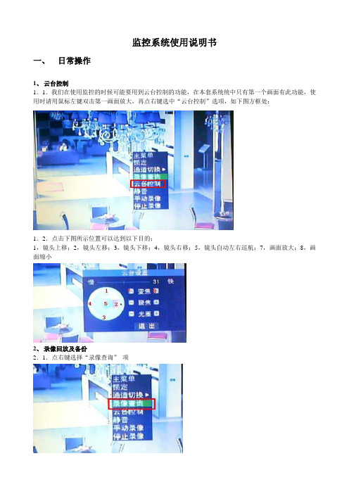
1、云台控制
1.1.我们在使用监控的时候可能要用到云台控制的功能,在本套系统统中只有第一个画面有此功能,使用时请用鼠标左键双击第一画面放大,再点右键选中“云台控制”选项,如下图方框处:
1.2.点击下图所示位置可以达到以下目的:
1,镜头上移;2,镜头左移;3,镜头下移;4,镜头右移;5,镜头自动左右巡航;7,画面放大;8,画面缩小
2、录像回放及备份
2.1.点右键选择“录像查询”项
2.2.在对话框中设好如下参数:
1,要查询的通道(窗口);2,录像开始的日期;3,录像开始的时间;4,点击“搜索”;5等待一段时间后搜索完成,再点击“详细文件”
2.3.如果画面显示的文件中有须要的时间段,选中方框处的位置再点击右下角的“备份”可以将录像内容拷贝备用(须要在前面板的USB口中插上自备的U盘,并保证U盘有大于256M的可用空间)。
如果画面中没有须要的时间段,可以点击“上一页”或“下一页”继续查找。
如果要回放录像内容请双击所查到的文件。
2.4.播放画提供以下操作功能:
1,多重速度倒放;2,多重速度慢放;3,正速度播放;4,画面暂停;5,多重速度前进;6,退出播放
二、日常维护
1、应经常擦拭设备表及摄像枪镜头的灰尘,以保证设备有较散热和图像的清晰;
2、不要在设备表面及周围堆放杂物,以免造成设备散热不良;
3、平时尽量关闭显示器的电源,以免缩短显示器使用寿命(显示器关闭后录像机仍然可以正常运作)。
CMS_使用说明书(中文)
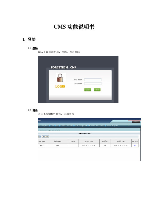
CMS功能说明书1.登陆1.1登陆输入正确的用户名,密码,点击登陆1.2退出点击LOGOUT 按钮,退出系统2.权限管理2.1管理员2.1.1增加输入正确的信息,点击提交,其中”admin authority” 在对应角色管理中的角色2.1.2删除勾选要删除的管理员,点击删除按钮2.1.3修改(1) 点击修改按钮(2) 修改完点击提交2.2角色管理2.2.1增加输入角色名,勾选要授予的权限,点击提交, 角色名不能跟已有的相同2.2.2删除勾选要删除的角色,点击删除按钮,如果角色已经授予给某一管理员,则无法删除, 若要删除必须先删除关联的管理员2.2.3修改(1) 点击修改按钮进入修改(2)点击提交保存修改的信息3.系统管理3.1服务器管理3.1.1增加服务器选择服务器类型,输入带星号的项,点击提交, 除了资源服务器,其他服务器只允许添加一台。
(1)资源服务器字段说明:输入服务器: 名任意字符服务器ID: 对应资源服务器提供的ID(2)CMS服务器字段说明:服务器名称:任意字符IP 地址:对应CMS服务器的IP地址端口:对应CMS服务器的端口Server id: 0(3)控制服务器字段说明:服务器名称:任意字符IP 地址:对应控制服务器的IP地址端口:9906Server ID: 0(4)P2P服务器字段说明:服务器名称:任意字符IP 地址:对应P2P服务器的IP地址端口:9907Server ID: 03.1.2删除服务器勾选要删除的服务器,点击删除, 此操作影响较大,将会导致客户端无法正常工作。
3.1.3修改服务器(1)点击修改按钮,进入修改(2) 输入正确的信息,点击提交, 具体填写的字段信息请参考添加的功能3.2日志管理3.2.1日志查询可以根据操作模糊查询,根据操作人查询,根据操作的时间段查询3.3数据库备份点击备份按钮,把整个数据库导出来。
4.直播4.1增加填写带星号的必填项,点击提交,其他项不用填写。
CMS使用说明书
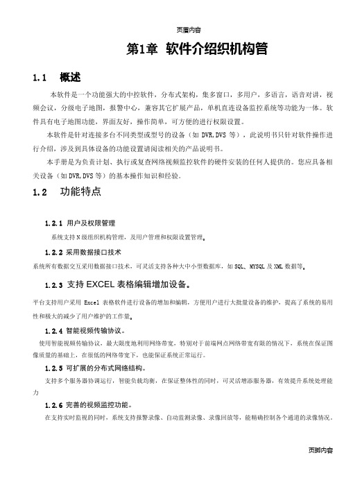
页眉内容第1章软件介绍织机构管1.1 概述本软件是一个功能强大的中控软件,分布式架构,集多窗口,多用户,多语言,语音对讲,视频会议,分级电子地图,报警中心,兼容其它扩展产品,单机直连设备监控系统等功能为一体。
软件具有电子地图功能,界面友好,操作简单,可方便的进行权限设置。
本软件是针对连接多台不同类型或型号的设备(如DVR,DVS等),此说明书只针对软件操作进行介绍,涉及到具体设备的功能设置请阅读相关的产品说明书。
本手册是为负责计划、执行或复查网络视频监控软件的硬件安装的任何人提供的。
您应具备相关设备(如DVR,DVS等)的基本操作知识和经验。
1.2 功能特点1.2.1用户及权限管理系统支持N级组织机构管理,及用户管理和权限设置管理。
1.2.2采用数据接口技术系统所有数据交互采用数据接口技术,可灵活支持各种大中小型数据库,如SQL、MYSQL及XML数据等。
1.2.3支持EXCEL表格编辑增加设备。
平台支持用户采用Excel表格软件进行设备的增加和编辑,方便用户进行大批量设备的维护,提高了系统的易用性和极大的减少了用户维护的工作量。
1.2.4智能视频传输协议。
使用智能视频传输协议,最大限度地利用网络带宽,特别对于前端网点网络带宽有限的情况下,系统在保证图像质量的基础上,在很低的网络带宽下,也能保证系统正常运行。
1.2.5可扩展的分布式网络结构。
支持多个服务器协调运行,智能负载均衡,在保证整体性的同时,可灵活增添服务器,有效提升系统处理能力1.2.6完善的视频监控功能。
在支持实时监视的同时,系统支持报警录像、自动监测录像、录像回放等,能精确控制各个通道的录像情况。
1.2.7动态调节解码缓冲。
实时监视时可灵活调节视频图像流畅性或实时性优先,流畅性讲求视频图像的流畅,实时性强调视频图像的实时,可满足不同用户的需求。
1.2.8采用货架技术,模块化开发,可灵活组装应用方案。
系统采用货架技术,分层及模块化开发,具有丰富的中件间服务,可以方便的进行各种应用方案的灵活组装。
CMS电脑监控使用方法
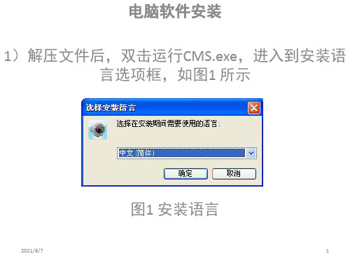
1)解压文件后,双击运行CMS.exe,进入到安装语 言选项框,如图1 所示
图1 安装语言
2021/6/7
2)点击【确定】,进入对应语言版本的CMS 安装 向导,如图2 所示,
图2 安装向导
2021/6/7
2
3)点击【下一步】,在后续弹出的设置向导中, 根据实际需要选择安装路径和附加图标位置,进入
到安装
界面,提示安装完成时,点【完成】即结束安装, 如图3 所示,
2021/6/7
3
4.确认监控主机有用网线连接到路由器的LAN接口 如下图所示
注! 不是连接到光纤猫哦!
2021/6/7
4
5.电脑添加监控设备
第一次打开监控软件,软件会自动搜索在局域网内 的监控设备,无需手动操作,即可实现电脑监控.
2021/6/7
10
感谢您的观看
2021/6/7
11
部分资料从网络收集整 理而来,供大家参考,
感谢您的关注!
2021/6/7
5
6.实时监控画面自动打开
2021/6/7
6
7.如电脑和监控设备不在一个局域网内
软件无法自动添加监控设备,需要手动添加监控设 备ID号.
2021/6/7
7
8.输入ID信息
2021/6/7
8
9.点击全部打开查看实时视频
2021/6/7
9
10.电脑查看监控录像视频
点击远程文件,查看监控主机硬盘录像文件,选择对 应的日期,通道,点击开始搜索,即可查看录像视频
- 1、下载文档前请自行甄别文档内容的完整性,平台不提供额外的编辑、内容补充、找答案等附加服务。
- 2、"仅部分预览"的文档,不可在线预览部分如存在完整性等问题,可反馈申请退款(可完整预览的文档不适用该条件!)。
- 3、如文档侵犯您的权益,请联系客服反馈,我们会尽快为您处理(人工客服工作时间:9:00-18:30)。
CMS监控系统说明书1.登录CMS有两种登录方式:本地用户登录和设备ID直接登录。
1.1. 本地用户登录双击桌面快捷方式,进入登录界面(如图1-1):(图1-1)用于登录的默认用户名和密码分别为:用户名:admin密码:空在成功登录了CMS系统之后,即显示其主界面(如图1-2)1.2. 设备ID登录(图1-3)1.在CMS系统的登录界面,点击【号码模式】按钮,在【设备号码】中输入所要连接主控的设备号码。
2.【查找设备】:点击【查找设备】按钮,可以把局域网中所有设备的ID号码都搜索出来,并显示在下拉列表中,用户可以选择设备号码并登录。
3.【高级设置】:高级设置中输入所连接主控的网络账号、密码.下面有两个权限:启用内网探测、以原始比例显示。
注:其中勾选启用内网探测:如果是在局域网内连接,选中此项。
广域网中,可不选;以原始比例显示:勾选此项后,可保证客户端显示的画面比例与主控端的画面比例一致。
(图1-4)(图1-5)2.CMS主要功能主要功能分布如下:2.1. 系统设置系统设置功能是CMS的最主要的功能,CMS连接主控的设置就是在这里设置的;(图2-1)系统设置包含:视频源与分组、本地用户、存储设置、高级设置四大功能,下面将逐一介绍2.1.1.视频源与分组1.分组设置:为方便用户在针对多组CMS应用,而增加的功能。
用户可以对一台主控服务器划分一个分组,以便管理。
2.当前组:显示的是当前组的信息,连接的时候,就是按照当前组来连接视频源;3.添加新组:可以添加新的分组;4.修改组名:可以将当前组的组名进行修改,修改完后点击一下【修改组名】按钮,就会修改成功;5.删除组:将当前组删除,但是不能删除最后一个分组。
6.组内视频源:分组内的所有视频源详细列表,选择某一路进行详细设置,每个视频源都有相应的通道对应。
】7.使用域名或IP连接:如果勾选此项,那么输入主控的IP就可以连接主控,一般情况下,端口、用户名、访问密码都为默认即可;不勾选此项,即用设备号码连接,在设备号码中输入从主控中获取的设备号码,进行连接(连接的前提是主控端的设备号码显示已上线);8.连接别名:为方便用户记忆而设的一项附加功能9.用户名:CMS连接主控所用到的网络用户名,在主控-【系统设置】-【用户管理】-【网络用户】中获取,不同的用户名对应不同的权限;10.访问密码:网络用户名所对应的密码;11.通道号:要连接主控的哪个通道,就在通道号中输入相应的数字,如要连接主控的第10个通道,那么通道号就输入10.12.使用内网探测:如果是在局域网中用设备号码连接,勾选此项,即可直接通过内网连接;如果是广域网,勾选此项没有意义。
13.接收远程报警信号:选择此功能可以接收主控端的报警信号。
14.开启悬浮窗口:勾选了此项,再开启悬浮窗口的时候,此通道画面才能悬浮在桌面上。
15.添加新源:即在一个分组内添加一个新的视频源。
16.删除最后源:删除排列在最下方的一个视频源。
17.默认设置:将所有设置内容恢复到默认状态下。
18.应用于全组:将当前视频源设置的所有功能内容应用到所有视频源通道。
19.保存本组设置:保存当前设置的视频源的内容。
20.解码卡功能介绍1)在使用解码卡功能前,需要在CMS端的PC机上装上解码卡,然后再装解码卡驱动,解码卡的驱动从【开始菜单】-【CMS】-【解码卡驱动安装】处即可安装。
2)上图表示视频源2关联至解码卡通道1,解码卡上的尾线V1接到视频线的一端,视频线的另一端接到监视器上,监视器上就会出现视频源2的图像;3)“位置”指的是输出的画面在监视器的哪个位置,其中0代表全屏;1代表左上方;2代表右上方;3代表左下方;4代表右下方。
如想把第1、2、3、4通道通过解码卡的第一个通道同时输出到监视器上,通道1设置:关联至解码卡通道“1”,位置“1”;通道2设置:关联至解码卡通道“1”,位置“2”;通道3设置:关联至解码卡通道“1”,位置“3”;通道4设置:关联至解码卡通道“1”,位置“4”;4)一台监视器最多能显示四个画面,如果有16个画面需要输出到1台监视器上,那么只能通过分组轮视的功能来实现。
21.启用数字矩阵输出功能介绍正常连接若干个视频输出设备的步骤如下所述:1)购买独立显卡,正确安装后开机,其安装图如2-2所示;请确保显卡驱动正确安装(建议安装驱动精灵进行显卡驱动的安装);(图2-2)2)将若干个视频输出设备同时连接到一个计算机的主机上,其图如2-3所示;(图2-3)3)鼠标右键单击计算机的桌面在弹出的右键菜单中选择“属性”子菜单,则系统弹出“显示属性”对话框,其图如2-4所示。
(图2-4)4)在图2-4界面中,鼠标单击“设置”页签,则打开设置界面,并在该界面中鼠标单击选择其它显示屏(如2),勾选“将Windows桌面扩展到该监视器上”复选框,其图如2-5所示,单击“确定”按钮即可将第一屏的内容扩展到其它屏上(如2)。
(图2-5)5)关联至通道:用于设置所关联的通道号。
6)位置:用于设置监控图像在上墙屏幕中的显示方式,其中0位置代表全屏显示,1位置代表显示在屏幕的左上角,2位置代表显示在屏幕的右上角,3位置代表显示在屏幕的左下角,4位置代表显示在屏幕的右下角。
2.1.2.本地用户设置(图2-6)该功能页表用于针对客户端用户进行权限设置和分配而建的。
在此您可以添加或删除新的用户登录名,或者修改原有用户名的权限。
2.1.3.存储设置(图2-7)该功能页表包含存放文件路径,文件打包时间和存放磁盘选择。
录像文件打包时间间隔是以分钟为单位的任意值,依用户个人而定。
录像文件存储磁盘选择则是除了系统盘无法作为存放磁盘外,其它磁盘可任意选择。
2.1.4.高级设置(图2-8)1.分组轮视间隔秒数:用于设置轮视所需的时间。
2.程序界面总在最前:当您选择该选项之后,本系统软件界面将会在任何情况下占用显示桌面,从而无法调用任何第三方软件界面。
3.当系统被锁定后禁止用户使用CTRL+ALT+DEL组合键:为防止非法用户在锁定下对软件进行破坏而设定无法使用该组合键,是一种预防功能。
4.开启设备管理:勾选此项,在主界面的右边才会出现【设备管理】按钮;5.启用自动更新:勾线此项,程序会自动检测最新软件并更新,重启以后就会自动升级为最新软件。
2.2. 全部连接连接远程图像按钮。
前提是在确认主控开启网络服务及CMS连接设置完成。
2.3. 全部断开断开所有已经连接的远程图像功能按钮。
2.4. 通道录像开启CMS软件录像功能按钮。
包括子菜单(全部录像,全部停录,开启录像和停止录像)。
2.5. 现场拍照针对CMS软件图像进行抓图功能。
拍完照以后可以从【更多功能】-【抓图管理】中查看图片。
2.6. 录像回放播放在CMS软件中记录的视频文件的功能,CMS中的录像回放功能跟主控中的录像回放功能是一样的,在这里不再做介绍。
2.7.更多功能具体功能列表如下:功能说明切换用户用于方便切换不同权限下的用户而设置的功能锁定系统对CMS软件进行操作锁定解锁系统解除软件的操作锁定分组轮视按不同画面数进行轮回显示系统日志记录操作信息及软件信息的列表图像管理用于浏览抓图的图片管理工具停止声卡报警停止由多种报警条件下引起的声卡报警声音清空CMS界面右下方的操作日志,但不完成删除该清空操作日志信息多画面组合方式,分1、4、9、16、25、36、49、画面分割64画面关于本系统显示本系统版本信息及所有权公司信息栏2.8. 远程云台控制CMS用户用以连接并控制服务端对应通道的云台控制功能。
2.9. 分组/远程回放/设备管理分组:想连接哪个分组的视频源,在下列表中选择即可;远程回放:远程回放主控的录像文件。
操作方法:连接主控,想查看哪个通道的远程录像,先用鼠标选中该通道,再点击【远程回放】-【远程检索】按钮,可以搜索到所选日期当天的主控的所有录像,双击录像文件即可播放;远程下载:检索出录像文件,还可以远程下载,即将主控的录像文件下载到本地。
注意:在下载过程中不可远程回放和录像,同样在远程回放时也不可以远程下载和录像。
设备管理:要想启用此项,需要在【系统设置】-【高级设置】中勾选【开启设备管理】项;设备管理功能可以搜索到局域网内的所有设备,包括DVR、IPC、视频采集卡的所有设备。
搜索到以后,可以双击IP下的通道直接连接。
2.10. 操作日志记录软件及操作信息的区域。
2.11. CMS的右键菜单功能右键菜单功能包括:连接本窗口、断开本窗口、录像本窗口、停录本窗口、播放声音、关闭声音、远程录像回放控制、开启主控录像、关闭主控录像、语音对讲、停止对讲、远程设置功能,下面将逐一介绍这些功能。
1.连接本窗口:连接鼠标所在窗口;2.断开本窗口:断开鼠标所在窗口;3.矩阵输入至:当已正常连接了两个或两个以上(需插入加密狗)的视频输出设备时,鼠标右键单击视频监控区,在弹出的右键菜单中选择“矩阵输出至”菜单项,则系统打开其子菜单项,选择“屏幕1”,且位置为0(0位置代表全屏显示,1位置代表显示在屏幕的左上角,2位置代表显示在屏幕的右上角,3位置代表显示在屏幕的左下角,4位置代表显示在屏幕的右下角),其界面如图2-9所示,其选择后的结果是另一个显示器中将全屏显示鼠标右键单击的监控画面。
其图如2-10所示。
(图2-9)(图2-10)4.录像本窗口:录像鼠标所在窗口,仅录制这一个窗口;5.停录本窗口:停止鼠标所在窗口的录像,仅停止这一个窗口的录像;6.播放声音:如果的通道上接了音频,并且在主控-【系统设置】-【压缩参数】中开启了【音视频压缩】,那么在CMS中点击播放声音,就会听到声音。
此时,CMS端录像也会将声音录制上。
如果主控端选择的是【视频压缩】那么,CMS端即使点击了播放声音,也不会听到声音;7.关闭声音:点击关闭声音,CMS将不再听到声音,此时,CMS录像中也不会有声音;8.远程录像回放控制:此功能是针对远程回放的时候进行的操作。
如远程回放时可以加速、减速、暂停、恢复播放;9.开启主控录像:可以开启CMS所连接通道的主控端的录像,即远程开启主控的录像。
CMS是否具有这一功能的权限取决于CMS连接用的网络用户名,如果网络用户有这一权限,那么CMS可以开启、关闭主控录像,如果没有这一功能,CMS将不能远程对主控的录像进行控制。
这一权限的设置在主控-【系统设置】-【用户管理】-【网络用户】中。
10.关闭主控录像:远程关闭主控的录像。
权限同上。
11.远程视频调节:用于调节音视频采集卡设备的视频图像,可调节其亮度、对比度、饱和度、色度、锐度及设置预置点功能。
12.语音对讲:CMS必须连接上主控后,才能开启此功能;13.停止对讲:停止语音对讲;14.远程设置:此功能主要针对DVR、IPC进行的设置。