MP118TH-C 规格书(1)
LM1117规格书
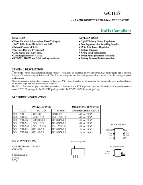
Load Regulation (Notes 2, 3) GC1117-3.3 GC1117-5.0 VIN = 4.75V, 0 ≤ IOUT ≤ 0.8A VIN = 6.5V, 0 ≤ IOUT ≤ 0.8A ∆VOUT , ∆VREF = 1%, IOUT = 0.8A (Note 4) (VIN - VOUT) = 1.5V (V IN - VOUT) = 1.5V (Note 5) (VIN - VOUT) = 1.5V 900
GENERAL DESCRIPTION
The The GC1117 series of adjustable and fixed voltage regulators are designed to provide up to0.8A outputcurrent and to operate down to 1V input-to-output differential. The dropout voltage of the device is guaranteed maximum 1.3V, decreasing at lower load currents. On-chip trimming adjusts the reference voltage to 1.5%. Current limit is set to minimize the stress under overload conditions on both the regulator and power source circuitry. The GC1117 devices are pin compatible with other t hree-terminal SCSI regulators and are offered in the low profile surface mount SOT-223 package, in the 8L SOIC package and in the TO-252 (DPAK) plastic package.
华联电子HPC814×-×光敏晶体管输出型光耦合器规格书说明书

产品规格书SPECIFICATION产品名称:光敏晶体管输出型光耦合器DESCRIPTION:Photo-transistor Output Opto-coupler产品型号:HPC814×-×PART NO.:HPC814×-×电话Tel :86-0592-*******传真Fax :86-0592-*******网址Web :地址:厦门市思明区前埔路502号Add :No.502,Qianpu Road,Siming District,Xiamen China邮编P.C.:36908拟制Prepared 审核Verified 批准Approved厦门华联电子股份有限公司Xiamen Hualian Electronics Corp.,Ltd.1概述General光敏晶体管输出型光耦合器是将红外LED芯片和光敏晶体管芯片封装在一起,以实现电一光一电转换。
产品见图1。
Photo-transistor Output Opto-coupler which is infrared LED chip andPhoto-transistor chip are assembled on lead frame,in order to change theelectricity-light-electricity.Products shown in Figure1.图1产品Figure1-Product 2特点Features●交流输入AC input●光敏晶体管输出Phototransistor output;●输入、输出端之间绝缘电压高Isolation voltage between input and output VISO≥5000Vrms●双列式塑料封装(DIP4L/SOP4L Plastic Package)●UL安全认证Safety certification of UL●VDE安全认证Safety certification of VDE●符合RoHS指令最新要求及REACH法规最新要求。
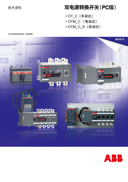
双电源转换开关-PC级
保安装备八件套之欧阳德创编

保安装备八件套保安装备有很多,常用的有下面几种:一、橡胶棍长度:85cm橡胶棍 RB85二、催泪喷射器成分:强烈的辛辣素-CS混合刺激剂尺寸:35mm*150mm喷射距离:大于4m喷射时间:大于4s喷射速度:大于8.0g/s有效期:3年质量:110g±5g执行标准:《GA884》三、强光手电筒功能:强光、弱光、爆闪尺寸:直径26×150(mm)电池容量:2200毫安灯泡寿命:10万小时亮度:100流明持续高亮照明:5小时电池使用寿命:重复充电1000次四、防割手套材料:防割材料、钢丝功能:防割、防划、防磨、抗酸抗碱五、防暴钢叉尺寸:长度190cm、杆体直径3.0cm、叉口直径:45cm材质:杆、叉采用不锈钢钢管手柄采用钢球或高强尼龙六、防刺背心内胆重量≤2.8kg防护面积≥0.3㎡颜色:警蓝七、防暴盾牌材料:透明塑料尺寸:900×500×3.5毫米重量:2.1千克八、对讲机技术参数:频率范围:VHF:136174MHzUHF:350390MHz、400450MHz、420470MHz、440490MHz输出功率:3.5W/1W信道数量:16尺寸:119*54*34mm防爆标志:E*ib IIB T3符合美国军标MILSTD810C/D/E/F亚音频、亚音数码、DTMF编码、2ToneHDC2400TM、HDC1200信令本质安全型1600mAh镍氢电池工作时间:约14小时紧急报警OX功能,使用耳咪时无需按下PTT键。
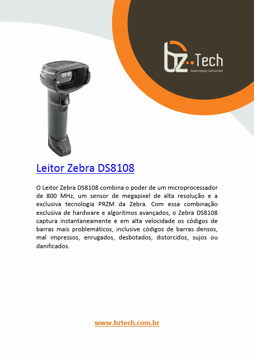
斑马技术公司DS8108数字扫描仪产品参考指南说明书
医用级 DC80480M070_X111_4C,86 盒 数据手册说明书
广州大彩光电科技有限公司版权所有版本记录版本日期修改原因页面撰写人审核人V1.02022/07/291、创建文档all傅家伟刘启鑫销售与服务广州大彩光电科技有限公司电话:************-601传真:************Email:*************(咨询和支持服务)网站:地址:广州黄埔区(科学城)玉树华新园C栋3楼网络零售官方旗舰店:成都分公司电话:188****6172地址:成都市高新区天府大道中段500号东方希望天祥广场C座39楼3910号目录1.硬件介绍 (1)1.1产品外观 (1)1.2硬件配置 (1)1.3调试工具 (2)2.产品规格 (3)3.产品尺寸 (5)4.引脚定义 (6)5.可靠性测试 (7)5.1ESD测试 (7)5.1.1执行标准 (7)5.1.2测试环境 (7)5.1.3测试数据 (8)5.2高低温老化测试 (8)5.2.1测试环境 (8)5.2.2测试数据 (9)5.3群脉冲测试 (9)5.3.1执行标准 (9)5.3.2测试环境 (9)5.3.3测试数据 (9)6.型号定义 (10)7.协议配置 (11)8.LUA脚本配置 (12)9.包装与物理尺寸 (13)10.产品架构 (14)11.开发软件 (15)11.1什么是虚拟串口屏 (15)11.2Keil与虚拟串口屏绑定调试 (16)12.开发文档 (17)13.免责声明 (18)1.硬件介绍本章节主要介绍产品的一些外观参考图、硬件配置图和调试所需工具。
1.1产品外观以下为该尺寸不同型号的外观参考图,如图1-1所示。
注:未涉及关键结构工艺修改或布局大调整,仅产品工艺或可靠性方面的变更迭代,公司不予对外发起变更,具体以收到的实物为准。
图1-17.0寸电容触摸参考图1.2硬件配置以下为该尺寸产品硬件配置参考图,如图1-2所示。
图1-2硬件配置图1.3调试工具以下为该产品调试工具参考图,以电容屏举例说明,如图1-3所示。
rbc-ascu11-c说明书
rbc-ascu11-c说明书RBC-ASCU11-C是一种高性能的直流电源模块,具有稳定的输出电压和大容量的电流输出能力。
该模块广泛应用于工业自动化控制系统、通信设备、医疗器械等领域。
本说明书将详细介绍RBC-ASCU11-C的特性、技术规格、安装方法和注意事项等内容。
1. 特性:RBC-ASCU11-C模块具有以下特性:- 宽输入电压范围:支持输入电压范围在100V至240V之间,适用于各种国家和地区的电力标准;- 高效能转换:采用先进的开关电源技术,转换效率高达90%以上,能够提供更稳定和可靠的电源输出;- 稳定的输出电压:输出电压范围可调,精度高,确保设备工作的稳定性;- 高容量输出电流:最大输出电流可达11安培,满足大容量设备的供电需求;- 保护功能完善:具有过载保护、过压保护、短路保护等多重保护措施,可有效保护设备免受损害。
2. 技术规格:- 输入电压范围:100-240V AC;- 输出电压范围:可调,建议3-24V DC;- 最大输出电流:11A;- 工作温度范围:-20℃至60℃;- 尺寸:100mm x 50mm x 30mm。
3. 安装方法:- 首先,将RBC-ASCU11-C模块安装在设备的电源板上,确保与设备的电路连接正确;- 然后,将输入电源插头插入交流电源插座,确保电源接地良好;- 最后,将输出端口连接到设备的待求电源接口,确保连接牢固。
4. 注意事项:- 在安装和使用过程中,请仔细阅读和遵守本说明书中的安全须知和操作说明;- 请确保输入电压符合本模块所支持的电压范围,否则可能导致设备损坏;- 请勿将本模块长时间暴露在高温、潮湿等恶劣环境中,以免影响模块性能和寿命;- 在使用过程中,如发现有异常情况(如过热、异味等),请立即停止使用并联系我们的技术支持。
总之,RBC-ASCU11-C是一款高性能直流电源模块,具有稳定的输出电压和大容量的电流输出能力。
本说明书中详细介绍了该模块的特性、技术规格、安装方法和注意事项,希望能够帮助用户正确安装和使用该模块,确保设备的正常运行和使用的安全性。
碧云天酶标仪用户手册说明书

质量保证........................................................................................................................................... 4
重要说明........................................................................................................................................... 5
1.2 仪器的光路系统.......................................................................................................7
1.3 规格和参数(包括 RS-232C 接口参数,打印机等) ...........................................8
2.4 屏幕介绍...................................................................................................................9
2.5 定义.........................................................................................................................10
3.5.5 记录查询.........................................................................................................32
FPGA可编程逻辑器件芯片XC7VX690T-2FF1158C中文规格书

7Series FPGAs Data Sheet: OverviewDS180 (v2.6.1) September 8, 2020Product SpecificationStacked Silicon Interconnect (SSI) TechnologyThere are many challenges associated with creating high capacity FPGAs that Xilinx addresses with the SSI technology. SSI technology enables multiple super logic regions (SLRs) to be combined on a passive interposer layer, using proven manufacturing and assembly techniques from industry leaders, to create a single FPGA with more than ten thousand inter-SLR connections, providing ultra-high bandwidth connectivity with low latency and low power consumption. There are two types of SLRs used in Virtex-7 FPGAs: a logic intensive SLR used in the Virtex-7 T devices and a DSP/blockRAM/transceiver-rich SLR used in the Virtex-7 XT and HT devices. SSI technology enables the production of highercapability FPGAs than traditional manufacturing methods, enabling the highest capacity and highest performance FPGAs ever created to reach production more quickly and with less risk than would otherwise be possible. Thousands of super long line (SLL) routing resources and ultra-high performance clock lines that cross between the SLRs ensure that designs span seamlessly across these high-density programmable logic devices.CLBs, Slices, and LUTsSome key features of the CLB architecture include:•Real 6-input look-up tables (LUTs)•Memory capability within the LUT •Register and shift register functionalityThe LUTs in 7 series FPGAs can be configured as either one 6-input LUT (64-bit ROMs) with one output, or as two 5-input LUTs (32-bit ROMs) with separate outputs but common addresses or logic inputs. Each LUT output can optionally be registered in a flip-flop. Four such LUTs and their eight flip-flops as well as multiplexers and arithmetic carry logic form a slice, and two slices form a configurable logic block (CLB). Four of the eight flip-flops per slice (one per LUT) can optionally be configured as latches.Between 25–50% of all slices can also use their LUTs as distributed 64-bit RAM or as 32-bit shift registers (SRL32) or as two SRL16s. Modern synthesis tools take advantage of these highly efficient logic, arithmetic, and memory features.Clock ManagementSome of the key highlights of the clock management architecture include:•High-speed buffers and routing for low-skew clock distribution •Frequency synthesis and phase shifting •Low-jitter clock generation and jitter filteringEach 7series FPGA has up to 24 clock management tiles (CMTs), each consisting of one mixed-mode clock manager (MMCM)and one phase-locked loop (PLL).Table 11:Virtex-7 HT FPGA Device-Package Combinations and Maximum I/Os Package (1)FLG1155FLG1931FLG1932Size (mm)35 x 3545 x 4545 x 45Ball Pitch1.0 1.0 1.0DeviceGTH GTZ I/O GTH GTZ I/O GTH GTZ I/O HP (2)HP (2)HP (2)XC7VH580T248400488600XC7VH870T 7216300Notes:1.All packages listed are Pb-free with exemption 15. Some packages are available in Pb option.2.HP = High-performance I/O with support for I/O voltage from 1.2V to 1.8V.7Series FPGAs Data Sheet: OverviewMixed-Mode Clock Manager and Phase-Locked LoopThe MMCM and PLL share many characteristics. Both can serve as a frequency synthesizer for a wide range of frequencies and as a jitter filter for incoming clocks. At the center of both components is a voltage-controlled oscillator (VCO), which speeds up and slows down depending on the input voltage it receives from the phase frequency detector (PFD).There are three sets of programmable frequency dividers: D, M, and O. The pre-divider D (programmable by configuration and afterwards via DRP) reduces the input frequency and feeds one input of the traditional PLL phase/frequency comparator. The feedback divider M (programmable by configuration and afterwards via DRP) acts as a multiplier because it divides the VCO output frequency before feeding the other input of the phase comparator. D and M must be chosen appropriately to keep the VCO within its specified frequency range. The VCO has eight equally-spaced output phases (0°, 45°, 90°, 135°, 180°, 225°, 270°, and 315°). Each can be selected to drive one of the output dividers (six for the PLL, O0 to O5, and seven for the MMCM, O0 to O6), each programmable by configuration to divide by any integer from 1 to 128. The MMCM and PLL have three input-jitter filter options: low bandwidth, high bandwidth, or optimized mode. Low-bandwidth mode has the best jitter attenuation but not the smallest phase offset. High-bandwidth mode has the best phase offset, but not the best jitter attenuation. Optimized mode allows the tools to find the best setting.MMCM Additional Programmable FeaturesThe MMCM can have a fractional counter in either the feedback path (acting as a multiplier) or in one output path. Fractional counters allow non-integer increments of 1/8 and can thus increase frequency synthesis capabilities by a factor of 8.The MMCM can also provide fixed or dynamic phase shift in small increments that depend on the VCO frequency. At 1600MHz, the phase-shift timing increment is 11.2ps.Clock DistributionEach 7series FPGA provides six different types of clock lines (BUFG, BUFR, BUFIO, BUFH, BUFMR, and the high-performance clock) to address the different clocking requirements of high fanout, short propagation delay, and extremely low skew.Global Clock LinesIn each 7series FPGA (except XC7S6 and XC7S15), 32 global clock lines have the highest fanout and can reach every flip-flop clock, clock enable, and set/reset, as well as many logic inputs. There are 12 global clock lines within any clock region driven by the horizontal clock buffers (BUFH). Each BUFH can be independently enabled/disabled, allowing for clocks to be turned off within a region, thereby offering fine-grain control over which clock regions consume power. Global clock lines can be driven by global clock buffers, which can also perform glitchless clock multiplexing and clock enable functions. Global clocks are often driven from the CMT, which can completely eliminate the basic clock distribution delay.Regional ClocksRegional clocks can drive all clock destinations in their region. A region is defined as an area that is 50 I/O and 50 CLB high and half the chip wide. 7series FPGAs have between two and twenty-four regions. There are four regional clock tracks in every region. Each regional clock buffer can be driven from any of four clock-capable input pins, and its frequency can optionally be divided by any integer from 1 to 8.I/O ClocksI/O clocks are especially fast and serve only I/O logic and serializer/deserializer (SerDes) circuits, as described in theI/O Logic section. The 7series devices have a direct connection from the MMCM to the I/O for low-jitter, high-performance interfaces.DS180 (v2.6.1) September 8, 2020Product Specification。
E-Plex 805OPM 8通道DC电源分配模块说明书

Design specifications• T ransient voltage suppression: EN6100-6-1.• P CB characteristics: UL 94V-0.• P ower distribution: UL 1077 compliant(except high-voltage dielectric test).• Load dump tested to ISO 16750-2.Key features• 8 channels with outputs capable of up to 15 ampseach (50 amps total).• P airs of channels may be configured to operate inparallel.• P WM dimming capability on all channels.• Input capability on all channels.• R everse battery protected.• S tatus LEDs for each channel.• T hermal, short circuit, and programmable overloadprotection.• L ocal manual override capabilities.• D esigned for motor and high inrush current loads.• E-Plex LEN value 2.Octal Power Module8 channel DC power distribution moduleElectrical specificationsNOTES:1. Module shuts down at 8.5 V and powers back up at 8.5 V2. S pecified as 50 feet of 2 AWG (43 mm²) wires with a 6 inch diameter spool for both power and ground.3. R efer to maximum load inductance graph below.Taking the device outside the limits specified above may cause permanent damage to the device.The supply to the module should be protected by a fuse or circuit breaker, 50 A maximumTrip speed characteristicsMaximum load inductanceE-Plex activity LEDE-Plex address indicationManual modeAt power up the module will indicate its E-Plex address by flashing the LEDs. One of the LEDs will flash for 2 seconds, this indicates the most significant digit of the address. This will be followed by one second with all LEDs off. Then another LED will flash to indicate the next digit of the address. This pattern will repeat until all 4 digits have been displayed. For example if LED 1 flashes followed by LED 6, then fault (0), then 8, the modules address is 1608.All LEDs flash repeatedly with the above sequence at power up if the module has not been assigned an address.Manual mode is a backup mode of operation which is automatically enabled if no commands are received from the main control unit (clock module). This allows for a minimum level of device control even when there are faults with other parts of the system.If a module is unprogrammed all channels are disabled.When the network is inactive there are two parameters that may be configured for output channels; automatic and manual control.Automatic controlWhen automatic control is enabled the channel can be set to turn its output on or off when the module enters manual mode. When disabled the output will remain in the same state as it was in before entering manual mode.Manual controlThe keypad switches may be programmed to override the automatic control with either momentary or latching behaviour.When the network is active the functionality of the buttons is determined by the system software.Typical wiring diagramNav equipmentHalogen lightingCable sizingPower / Battery Connections: Must be protected at a maximum of 50 A. Maximum wire size should be sized based on upstream fuse. When connecting the power source to the power studs on the module, the M5 hex nuts should be torqued to 3 Nm (22 in lb) after installing the battery terminals to the studs. Failure to properly torque hex nuts may result in intermittent operation due to terminals loosening over time.Nut (torque to 3 Nm)Spring washerFlat washerRing terminal805OPMMechanical specificationsMounting instructionsScrew assembly to a flat mounting surface in two places, as shown in the illustration labels A and B. Use M4 size panhead screw, M4 split lock washer and M4 washer or No. 6 wood screw Torque to 250~280 N-cm. Do not exceed this torque as it could cause damage to the enclosure.NOTES:1. Outputs shut down at 80 ºC and come back on at 75 ºC.Taking the device outside the limits specified above may cause permanent damage to the device.Parallel OperationWhen paralleling channels, it is important to match the resistance of the wires from each channel. If the wires are not balanced, one will carry more current than the other, which may result in the channel tripping prematurely. The remaining channel will then have to carry the entire load current, and will also trip. The best way to ensure that the wires are matched is to join them as close to the module a possible using wires of equal length and cross sectional area. This should be 4 mm 2 (14 AWG) wire, no longer than 100 mm (4”). E-Plex Ltd. can supply a pre-made assembly for this purpose. See below for ordering code.Loads with multiple suppliesWhen a channel is used to power a load it is necessary to fit a back feed prevention diode to protect against equipment damage when the OPM channel is off but the other channel is on. E-Plex Ltd. can supply a back feed diode with integral resister which will protect against back feeding whilst still allowing feed back to be monitored. See below for ordering code.Ordering codesPowering Systems - Empowering Designers52 – 54 Riverside, Sir Thomas Longley Road, Medway City Estate, Rochester, Kent ME2 4DPtel: +44 (0)1634 711622 fax: +44 (0)1634 290773email:***************web: www.e-plex.coImportant Notice: E-Plex Ltd. (E-Plex) reserves the right to make changes to or discontinue any product or service identified in this publication without notice. E-Plex advises its customers to obtain the latest version of the relevant information to verify, before placing any orders, that the information being relied upon is current. E-Plex assumes no responsibility for infringement of patents or rights of others based on E-Plex applications assistance or product specifications since E-Plex does not possess full access concerning the use or application of customers’ products. E-Plex also。
MAX118

Σ
REF+ 16
4-BIT DAC
THREESTATE OUTPUT DRIVERS D3 D2 D1 D0
4-BIT FLASH ADC (4LSBs) TIMING AND CONTROL
ADDRESS LATCH DECODE
MAX114/MAX118
A0 * MAX118 ONLY A1 A2 REFRD CS PWRDN MODE WR/RDY INT
19-1083; Rev 1; 8/96
+5V, 1Msps, 4 & 8-Channel, 8-Bit ADCs with 1µA Power-Down
_______________General Description
The MAX114/MAX118 are microprocessor-compatible, 8-bit, 4-channel and 8-channel analog-to-digital converters (ADCs). They operate from a single +5V supply and use a half-flash technique to achieve a 660ns conversion time (1Msps). A power-down ( PWRDN ) pin reduces current consumption typically to 1µA. The devices return from power-down mode to normal operating mode in less than 200ns, allowing large supplycurrent reductions in burst-mode applications (in burst mode, the ADC wakes up from a low-power state at specified intervals to sample the analog input signals). Both converters include a track/hold, enabling the ADC to digitize fast analog signals. Microprocessor (µP) interfaces are simplified because the ADC can appear as a memory location or I/O port without external interface logic. The data outputs use latched, three-state buffer circuitry for direct connection to an 8-bit parallel µP data bus or system input port. The MAX114/MAX118 input/reference configuration enables ratiometric operation. The 4-channel MAX114 is available in a 24-pin DIP or SSOP. The 8-channel MAX118 is available in a 28-pin DIP or SSOP. For +3V applications, refer to the MAX113/MAX117 data sheet.
E103-W08 产品规格书说明书

E103-W08产品规格书2.4G串口WIFI BLE配网低功耗目录第一章概述 (1)1.1简介 (1)1.2功能特点 (1)1.3应用场景 (2)第二章规格参数 (2)2.1极限参数 (2)2.2工作参数 (2)第三章机械尺寸与引脚定义 (3)3.1E103-W08A引脚尺寸图 (3)3.2E103-W08A引脚尺寸图 (4)第四章推荐连线图 (5)第五章功能说明 (5)5.1工作模式 (5)5.1.1TCP通信 (6)5.1.2MQTT通信 (7)5.1.3HTTP通信 (7)5.2TCP心跳包 (7)5.3自动连接 (7)5.4手动连接 (8)5.5手动断开 (8)5.6BLE配网 (8)5.7状态指示 (8)5.8低功耗 (8)5.9注意事项 (9)第六章默认参数 (9)第七章AT指令及参数 (10)7.1错误码表 (11)7.2基本AT指令 (11)7.2.1AT测试指令 (11)7.2.2重启模块 (11)7.2.3恢复出厂参数 (12)7.2.4查询版本信息 (12)7.2.5查询、设置串口参数 (12)7.2.6查询、设置工作模式 (12)7.2.7查询、设置电源模式 (13)7.3WIFI相关AT指令 (13)7.3.1扫描可用AP (13)7.3.2连接到指定AP (13)7.3.3与AP断开连接 (14)7.3.4查询、设置连接模式 (14)7.3.5查询MAC地址 (14)7.3.6查询、设置主机名 (14)7.4TCP相关AT指令 (15)7.4.1查询网络连接状态 (15)7.4.2建立TCP传输 (15)7.4.3关闭TCP传输 (15)7.4.4查询本地IP (15)7.4.5查询、设置多连接 (15)7.4.6查询、设置TCP模式 (15)7.4.7查询、设置是否打印对端IP、端口 (16)7.4.8查询、设置远程目标参数 (16)7.4.9查询、设置心跳数据 (16)7.5MQTT相关AT指令 (17)7.5.1查询、设置MQTT远程目标 (17)7.5.2查询、设置MQTT发布主题 (17)7.5.3查询、设置MQTT订阅主题 (17)7.5.4查询、设置MQTT登录参数 (17)7.5.5查询、设置MQTT连接参数 (18)7.6HTTP相关参数 (18)7.6.1查询、设置远程目标 (18)7.6.2查询、设置URL (18)7.6.3查询、设置数据类型 (18)7.7BLE相关参数 (19)7.7.1查询、设置BLE广播名 (19)7.7.2查询、设置BLE广播间隙 (19)第八章使用教程 (20)8.1TCP通信 (20)8.1.1透传 (20)8.1.2协议传输 (21)8.2HTTP通信 (23)8.3MQTT通信 (23)8.4BLE配网 (24)第九章焊接作业指导 (27)9.1回流焊温度 (27)9.2回流焊曲线图 (27)修订历史 (28)关于我们 (28)免责申明和版权公告本文中的信息,包括供参考的URL地址,如有变更,恕不另行通知。
Thecus N4100PRO 使用说明

使用说明版权和商标公告ndows, Thecus和Thecus产品的其他名字的注册商标为Thecus科技有限公司。
Microsoft, Wi和Windows标志的注册商标为微软公司。
Apple, iTunes和Apple OS X的注册商标为苹果电脑公司。
所有其他商标和品牌名称都是他们各自的所有人的财产。
如未经通知,说明书以改版为准。
版权(C) 2008 Thecus 科技公司。
版权所有关于这份手册这份手册里的所有信息已经很被仔细地核实,以确保它的正确性。
如果发生错误,请给我们反馈。
在未通知的情况下,Thecus科技公司对这份手册内容的修改保留权利。
产品名称: Thecus N4100PRO手册版本: 1.2出厂日期2008年10月有限担保Thecus科技公司担保Thecus N4100PRO的所有部件在他们离开工厂之前都经过全面地测试,还有必须在一般使用的情况下能正常地运作。
一旦发生任何系统故障,如果产品在保修期内,在正常使用的情况下出现故障,Thecus科技公司,当地代表和经销商有责任对客户进行免费保修。
Thecus科技公司不对任何由产品引起的任何数据损坏或损失负责任。
强烈推荐用户进行必要的备份操作。
安全警告对于您的安全方面,请阅读并按照下面的安全警告。
请在安装您的N4100PRO.之前全面地阅读这份手册。
你的N4100PRO是一复杂的电子设备。
不要在任何情况下尝试修理它。
在发生故障的情况下,立即关掉电源,然后到合格的服务中心修理。
对于细节方面联系你的经销商。
不要在电源线上放置任何东西。
不要把电线放在任何可以被踏着走的地方。
谨慎地放好连接电缆,避免他们受到踩踏。
在温度为0°C 和40°C 之间,伴随着20% – 85%的相对湿度,你的N4100PRO可以正常运作。
在极端的环境条件下使用N4100PRO可能会损坏它。
确保给N4100PRO正确地供电(AC 100V ~ 240V, 50/60 Hz,3A). 把N4100PRO插到不正确的电源会被损坏。
易维斯 泽尼斯 热升华塑料卡打印机操作手册说明书

FLEXIBILITY• W ith Zenius, you can choose to insert your cards individually or with the automatic feeder.• T he «Expert» version of Zenius features combinable encoding functions: magnetic encoding, contact and contactless chips. It takes just a few minutes to install these modules!EASE OF USE• W ith the Evolis Premium Suite ®software, you can receive notifications and easily control the printer from your computer.• E volis High Trust ® ribbons are easy to install and automatically recognized and set by the printer.SMALL FOOTPRINT• H ardly larger than a standard sheet of paper, Zenius fits perfectly into any environment, be it the office or a customer service counter.• Z enius is an eco-designed printer: very efficient sleep mode and low energy consumption.The Zenius printer is designed for single sided printing and encoding of a very large variety of plastic cards. Zenius generates color or monochrome cards, individually or in small runs, with top quality results. Zenius is a user-friendly, compact and cost-effective solution for delivering your personalized cards.ZENIUSTHE COMPACT AND AGILE CARD PRINTER©2015 Evolis. All rights reserved. Actual product(s) may differ from information stated in this document. All specifications or pictures are subject to change without prior notice. All trademarks mentioned herein belong to their respective owners. Pictures: Olivier Calvez. 07/2015. KB-ZEN1-064-ENG-A4 Rev D0. MK000494EUROPE - MIDDLE-EAST - AFRICAEvolis - 14 avenue de la Fontaine - ZI Angers-Beaucouzé 49070 Beaucouzé - FranceT +33 (0) 241 367 606 - F +33 (0) 241 367 612 - info @AMERICAS - Evolis Inc. - Fort Lauderdale - evolisinc @ ASIA-PACIFIC - Evolis Asia Pte Ltd - Singapore - evolisasia @ CHINA - Evolis China - Shanghai - evolischina @ INDIA - Evolis India - Mumbai - evolisindia @MANUAL OR AUTOMATIC CARD FEEDERGENERAL FEATURES• Direct-to-card dye-sublimation/Resin thermal transfer • Single-sided printing, edge-to-edge • 300 dpi print head (11.8 dots/mm)• 16 million colors• 16 MB memory (RAM)PRINTING PERFORMANCES• C olor (YMCKO): 120 - 150 cards/hour 1• Monochrome: 400 - 500 cards/hourINTERFACES• U SB (1.0, 1.1, 2.0, 3.0), cable supplied • E thernet TCP-IP 10BaseT, 100BaseT (Traffic Led) on the Expert versionCARD MANAGEMENT AND SPECIFICATIONS• A utomatic or manual feeding• Feeder capacity: 50 cards (0.76 mm – 30 mil)• O utput hopper capacity: 20 cards (0.76 mm – 30 mil)• C ard thickness: 0.25 to 0.76 mm (10 to 30 mil), gauge adjustment • C ard types: PVC cards, composite PVC cards, PET cards, ABS cards 1, special varnished cards 1• C ard format: ISO CR80 - ISO 7810 (53.98 mm x 85.60 mm)OPTIONAL FEATURES• C olors available: fire red & grey brown• E xpert version: Ethernet TCP-IP, encoding modules as optionsADDITIONAL ENCODING MODULES•A vailable modules:- Magnetic stripe encoder ISO 7811 HiCo/LoCo, JIS2 - Smart contact station ISO 7816-2- Contact smart card encoder - PC/SC, EMV 2000-1- C ontactless smart card encoder - ISO 14443A, B, ISO15693, MIFARE, DESFire, HID iCLASS - Other specific encoders upon request • I nternal USB or IP ports • O ptions can be combined • F actory-installed or installed on siteSAFETY• S upport for Kensington ® security lock • D ata encryption for magnetic encodingDISPLAY•P rinter LEDs• G raphical notifications from the printer 2: cleaning alerts, empty/low level ribbon and card alerts, etc.EVOLIS HIGH TRUST ® RIBBONSTo maximize the quality and durability of printed cards, the lifespan of the print head and the overall printer reliability, use Evolis High Trust ® ribbons.• A utomatic identification and setting • D elivered in a drop-in cassette for easy handling • R ibbon saver for monochrome printing List of ribbons available on SOFTWARE• D elivered with Evolis Premium Suite ® for Windows ®:- Printer driver - E volis Print Center for administration and settings - Evolis Printer Manager for graphical notification 3 - 24/7 online support - C ompatible with Windows ® (32/64 bits): XP SP3, Vista, W7, W8, W10• D elivered with cardPresso XXS Lite for designing and editing badges:- Internal database up to 50 records- Windows ® (from XP onwards) and Mac OS X • D elivered with a driver for Mac OS X (from 10.5 onwards)• L inux OS upon request • E volis Premium SDK for remote supervision of the printer, while facilitating and speeding up integration into IT systemsECO-FRIENDLY DESIGN, CERTIFICATIONS AND STATEMENT OF COMPLIANCE• S tandby, sleep modes & reduced energy consumption • C E, FCC, IEC, VCCI, CCC, KC, BIS, EAC •R oHSSIZE AND WEIGHT• S ize (H x W x D): 195 x 205 x 315 mm (7.68’’ x 8.07’’ x 12.4’’)• W eight: 3.3 kg (7.3 lbs)WARRANTY• 2-year warranty (printer and print head)4• W arranty extension available as an optionMAIN FEATURES / Full technical specifications on Easy handling, automatic ribbonrecognition and setupW eight: 3.3 kg (3.64 lbs)315 mm (12.4’’)195 mm (7.68’’’)205 mm (8.07’’)1 Under specific conditions /2 Depends on the Windows version /3 Requires the .net 4.0 client profile version4 Warranty subject to observance of specific conditions and use of Evolis High Trust ribbonsALC Technologies Pte LtdBlk 998 Toa Payoh North #07-07/08/09318993 Singapore SingaporeTel : 63541650Fax : 63544595E-mail:*******************Web : 。
迅迪电子 XD308H 宽输入电压范围降压型 DC DC 转换器规格书说明书
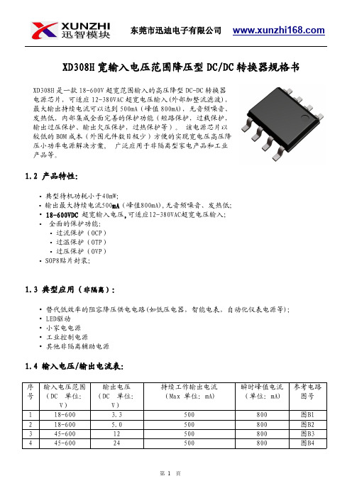
XD308H 宽输入电压范围降压型DC/DC 转换器规格书1.2产品特性:•典型待机功耗小于40mW;•输出最大持续电流500mA (峰值800mA),无音频噪音、发热低;•18-600VDC 超宽输入电压,可适应12-380VAC超宽电压输入;•全面的保护功能:•过流保护(OCP)•过温保护(OTP)•过压保护(OVP)•SOP8贴片封装;1.3典型应用(非隔离):•替代低效率的阻容降压供电电路(如低压电器,智能电表,自动化仪表电源等);•LED驱动•小家电电源•工业控制电源•其他非隔离辅助电源1.4输入电压/输出电流表:序号输入电压范围(DC 单位:V)输出电压(DC 单位:V)持续工作输出电流(Max 单位:mA)瞬时峰值电流(单位:mA)参考电路图号118-600 3.3500800图B1218-600 5.0500800图B2345-60012500800图B3445-60024500800图B4XD308H 是一款18-600V 超宽范围输入的高压降型DC-DC 转换器电源芯片,可适应12-380VAC 超宽电压输入(外部加整流滤波),最大输出持续电流可以达到500mA(峰值800mA),无音频噪音、发热低,内部集成全面完善的保护功能(短路保护,过载保护,输出过压保护、输出欠压保护,过热保护等)。
该电源芯片以较低的BOM 成本(外围元件数目极少)方便的实现宽电压高压降压小功率电源解决方案,广泛应用于非隔离型家电产品和工业产品等。
1.5封装参考:1.6引脚功能:编号名称描述备注1VCC/BP所有控制电路的电源。
外部旁路电容连接点2GND/S芯片参考地。
内部功率MOSFET的源极。
3FB反馈输入4CS电流检测5,6,7,8DRAIN内部功率MOSFET的漏极1.7功能框图:图11.8典型应用电路:1.9绝对最大额定值(备注1):1.10推荐的工作条件(备注2):参数数值单位工作环境温度-40to85°C1.11电气特性:=+25℃。
CSA 标记商品说明书 - 易用819-AC-RC、易用819-DC-RC、易用820-DC-RC、

Certificate of ComplianceCertificate:1389312 (LR 12528)Master Contract:165628Project:2598260Date Issued:February 14, 2013DQD 507 Rev. 2012-05-22Page: 1Issued to:Eaton Industries GmbHHein-Moeller-Strasse 7-11Bonn, 53115GermanyAttention: Barbara Skupin The products listed below are eligible to bear the CSA Mark shownSimon Vorasane Eng.Issued by:Simon V orasane Eng.PRODUCTSCLASS 2258 02- PROCESS CONTROL EQUIPMENT - For Hazardous Locations CLASS 2253 51- PROGRAMMABLE CONTROLLERPart A: CLASS 2258 02 - PROCESS CONTROL EQUIPMENT - For Hazardous LocationsClass I Division 2 Groups A, B, C and D Temperature Code T3C-160ºC in 55ºC ambient.Programmable Controller, open type, DIN rail mounted, Model Nos. Easy 819-AC-RC (X), suffix X without display, supply 115-240vac 50/60Hz; Easy 819-DC-RC (X), Easy 820-DC-RC (X), Easy 821-DC-TC (X),Easy 822-DC-TC (X), supply 24vdc. Accessories Easy 800-PC-CAB, Easy800-USB-CAB, Easy800-MO-CAB, Easy-M-256K, EU4A-MEM-CARD1, Easy-NT-RJ45, Easy-NT-R/-30/-80/-150/-CAB, Bluetooth Adapter EASY800-BLT-ADP.Programmable Controller, open Types, Model Nos. Easy Control EC4P-221(222)-MTXD, EC4P-221(222)-MTXX, EC4P-221(222)-MRXD, EC4P-221(222)-MRXX, EC4P-221(222)-MTAD. EC4P-221(222)-MTAX,EC4P-221(222)-MRAD1, EC4P-221(222)-MRAX followed by different numbers, EC4E-221-6D4T1,EC4E-221-6D4R1.Maximum operating ambient +55°C.Note: These modules are certified for use in other equipment where the suitability of the combination is determined by CSA or local inspection having jurisdiction.Certificate:1389312 (LR 12528)Master Contract:165628Project:2598260Date Issued:February 14, 2013DQD 507 Rev. 2012-05-22Page: 2PART B: CLASS2253 51 - PROGRAMMABLE CONTROLLERProgrammable Controller, open types, Model Nos. Easy 819-AC-RC (X), Easy 819-DC-RC (X), Easy 820-DC-RC (X), Easy 821-DC-TC (X), Easy 822-DC-TC (X)Programmable Controller, open Types, Model Nos. Easy Control EC4P-221(222)-MTXD, EC4P-221(222)-MTXX, EC4P-221(222)-MRXD, EC4P-221(222)-MRXX, EC4P-221(222)-MTAD. EC4P-221(222)-MTAX,EC4P-221(222)-MRAD1, EC4P-221(222)-MRAX followed by different numbers, EC4E-221-6D4T1,EC4E-221-6D4R1.Same model number and electrical ratings as in Part A above, except for use in ordinary locations, general use.APPLICABLE REQUIREMENTSCSA Std C22.2 No. 0.4-04 Bonding and Grounding of Electrical Equipment (Protective Grounding)CSA Std C22.2 No. 142-M1987 - Process Control EquipmentCSA Std C22.2 No. 213-M1987 - Non-Incendive Electrical Equipment for Use in Class I, Division 2Hazardous LocationsCAN/CSA-E61131-2:06 - Programmable Controllers-Part 2: Equipment Requirements and Tests。
易川科技 DC DC 电源模块 - 定压系列 产品选型表说明书

选型表●Isolation voltage 1.5KVdc ●range: -40 ~ +105°C ambient ●RoHS compliant●Industrial standard DIP4 package ●Certified to CE●Input/ Output Isolation Voltage:1.5kvdc输入特性输出特性通用特性物理特性产品特性曲线图外观尺寸/建议印刷版图Vin(VDC) Cin(µF) Vo(VDC) Cout(µF )3.3/54.7 3.3/5 10 12 2.2 9 4.7 15 2.2 12 2.2 24 1 15 1 ----240.47推荐容性负载值表(表1) 推荐电路参数值表注:尺寸单位:mm[inch] 端子直径公差:±0.10[±0.004] 未标注之公差:±0.50[±0.020]引脚 功能 1GND 2 Vin 3-Vo 4+VoNC :不能与任何外部电路链接1. 典型应用若要求进一步减小输入输出纹波,可在输入输出端连接一个电容滤波网络,应用电路如图4所示。
但应注意选用合适的滤波电容。
若电容太大,很可能会造成启动问题。
对于每一路输出,在确保安全可靠工作的条件下,推荐容性负载值详见表1。
2.EMC典型推荐电路见图5标注:✧输入电压不能超过所规定范围值,否则可能造成永久性不可恢复的损坏;✧如没有特殊说明,本手册的参数都在25℃,湿度40%~75%,输入标称电压和输出纯电阻模式满负载下测得;✧所有指标测试方法均依据本公司企业标准。
中山市易川电子科技有限公司销售邮箱:******************技术支持邮箱:**************。
- 1、下载文档前请自行甄别文档内容的完整性,平台不提供额外的编辑、内容补充、找答案等附加服务。
- 2、"仅部分预览"的文档,不可在线预览部分如存在完整性等问题,可反馈申请退款(可完整预览的文档不适用该条件!)。
- 3、如文档侵犯您的权益,请联系客服反馈,我们会尽快为您处理(人工客服工作时间:9:00-18:30)。
MEGMEET 麦格米特电气技术有限公司MEGMEET ELECTRICAL TECHNOLOGY CO., LTD.DESCRIPTION:(规格书)SPECIFICATIONTHESE SPECIFICATION ARE THE PROPERTY OF MEGMEET ELECTRICAL TECHNOLOGY CO., LTD Model No.:Meet with mega satisfaction承认书SPECIFICATION FOR APPROVALPart No. MP118TH-C Description: LCD Power Supply Specification Revision: 1.0 Customer. Customer Approval No. :承认鉴章后请寄回承认书正本一份Please return to us one original of “SPECIFICATION FOR APPROV AL” w ith your approved signatures.承认书APPROVED SIGNATURES核准人 APPROVED BY : 日期 DATE :盖章鉴署 CHOP & SIGNATURES:深圳市麦格米特电气技术有限公司SHENZHEN MEGMEET ELECTRICAL TECHNOLOGY CO.,LTDAdd: 2F Union Bldg., 1069 Nanhai Blvd. Shekou .Shenzhen, ChinaZIP CODE:518067TEL: (0755)26805000 FAX: (0755)26805099E-mail: megmeet@MEGMEET 麦格米特电气技术有限公司MEGMEET ELECTRICAL TECHNOLOGY CO., LTD.DESCRIPTION:(规格书)SPECIFICATIONTHESE SPECIFICATION ARE THE PROPERTY OF MEGMEET ELECTRICAL TECHNOLOGY CO., LTD Model No.:Spec. Rev. Sampl Rev. Date Description Safety by Mechanica by Electrical by1.0 1.1 2010.06.22 shenchuchun zhan xing guichengcaiMEGMEET 麦格米特电气技术有限公司MEGMEET ELECTRICAL TECHNOLOGY CO., LTD.DESCRIPTION:(规格书)SPECIFICATIONTHESE SPECIFICATION ARE THE PROPERTY OF MEGMEET ELECTRICAL TECHNOLOGY CO., LTD Model No.:Section 目录1. Power supply overview 电源性能指标1.1 Input Electrical Characteristics Overview (输入特性) 1.2 Output Electrical Characteristics Overview (输出特性)1.2.1 Output V oltage ,Current & Regulation.(输出电压电流调整率) 1.2.2 DC Output Ripple & Noise. (输出纹波和噪声) 1.2.3 Output Transient Response. (输出动态响应) 1.2.4 DC Output Hold-Up Time. (输出保持时间)1.2.4 DC Output Overshoot At Turn On & Turn Off.(输出超调) 1.2.6 DC output voltage rise time (输出上升时间) 1.3 Remote On/Off Control :(遥控功能) 1.4 Protection: (保护功能) 1.4.1 DC output Over V oltage Protection. (输出过压保护) 1.4.2 DC Output Over current Protection. (输出过流保护) 1.4.3 DC Output Short Circuit Protection. (输出短路保护) 1.4.4 Reset After Shutdown.(保护功能复位)2. Isolation 绝缘性能3. Safety 安全规格4. EMC 电磁兼容性4.1 EMI (电磁干扰) 4.2 EMS (电磁抗扰)5. Environmental Requirement 环境 5.1 Temperature (环境温度)5.2 Humidity (环境湿度) 5.3 Altitude (海拔高度)5.4 Cooling Method (冷却方式) 5.5 Vibration (振动耐受) 5.6 Impact (冲击耐受)6. Dimension (物理尺寸)7. Weight (重量)8. Pin Connection (连接器脚位定义)9. Power Supply mounting (安装尺寸)10. Package (包装)MEGMEET 麦格米特电气技术有限公司MEGMEET ELECTRICAL TECHNOLOGY CO., LTD.DESCRIPTION:(规格书)SPECIFICATIONTHESE SPECIFICATION ARE THE PROPERTY OF MEGMEET ELECTRICAL TECHNOLOGY CO., LTD Model No.:1. Power Supply Overview 电性能指标:1.1 Table 1 Input Electrical Characteristics Overview (输入特性)Input voltage range 输入电压 90Vac to 264Vac Normal voltage range 标称输入 100Vac to 240Vac Frequency range 频率范围 50Hz/60Hz±5%Max input ac current满载输入电流2.6Amax at full load and 90Vac condition Inrush current (cold start)浪涌电流50Atyp peak, 120Vac; 100Atyp peak, 220Vac Efficiency(full load) 效率 82%min at 90Vac; 86%min at 220Vac Typ. Harmonic current 谐波电流 Meet GB17625.1-2003/IEC61000-3-2 class D Leakage Current 泄漏电流 Less Than 0.5mA at 240Vac inputStandby Power Loss 待机功耗 ≦0.5W 240Vac input at 5Vsb Output current≤10mA Input Fuse 输入保险T5AH/250Vac1.2 Output Electrical Characteristics Overview (输出特性) 1.2.1 Table 2 Output V oltage ,Current & Regulation.(输出调整率)Output V oltage 输出电压 Regulation 调整率 Min. current 最小电流 Load current range 带载电流范围 Peak current or power峰值电流或功率 +V1(+24V) +V1±5% 0.2 A 0.2A-5A≤190W +V2(+12V) +V2±5% 0.3 A 0.3A-3.5A+5.0V +5.2V ±2%0.1 A 0.1A-1.5A≤15W+5.0V(SB) +5.2V ±2%0.01 A 0.01A-1ANote:* The peak current or power should be test at other of dc output at Rated load ,And the peak current pulse width within 100ms 峰值电流或功率的测试是在其它额定负载时测试,且脉宽小于100毫秒。
1.2.2 Table 3 DC Output Ripple & Noise. (输出纹波和噪声)Output V oltageRipple & Noise (Max.)+V1(+24V)240mVp-p@25℃; 350mVp-p@-10℃ +V2(+12V)120mVp-p@25℃; 200mVp-p@-10℃ +5.0V50mVp-p@25℃; 150mVp-p@-10℃; +5.0V(SB)60mVp-p@25℃; 200mVp-p@-10℃; 150mVpp when STB Note: 1) Measurements shall be made with an oscilloscope with 20MHz bandwidth. 示波器须设置在20兆赫兹带宽2) Outputs shall be bypassed at the connector with a 0.1uF ceramic capacitor and a10uF electrolytic capacitor to simulate system loading.输出须并联0.1uF 的陶瓷电容和10uF 的电解电容来模拟负载MEGMEET 麦格米特电气技术有限公司MEGMEET ELECTRICAL TECHNOLOGY CO., LTD.DESCRIPTION:(规格书)SPECIFICATIONTHESE SPECIFICATION ARE THE PROPERTY OF MEGMEET ELECTRICAL TECHNOLOGY CO., LTD Model No.:1.2.3 Output Transient Response. (输出动态响应)Table 4. Test condition.测试条件V oltage Tolerance Limit Slew Rate Load Change 5.0V/5.0VS ±5% 24V/12V/±10% 0.2A/uS Min. to 50% load and 50% to Max load All output±10% 0.2A/uS Min. load to Max loadNote: Transient response measurements shall be made with a load changing repetitionrate of 50Hz to 10kHz. 以50~10KHz 的频率跳变负载来测试。
