ps快捷键大集合
ps常用快捷键大全
ps常用快捷键大全PS常用快捷键大全。
Adobe Photoshop(简称PS)是一款功能强大的图像处理软件,它可以帮助用户进行照片修饰、图像设计等工作。
在日常使用中,熟练掌握快捷键可以大大提高工作效率。
下面是PS常用快捷键的大全,希望对大家有所帮助。
1. 新建文件,Ctrl + N。
快速新建一个文件,可以自定义文件的尺寸、分辨率等参数。
2. 打开文件,Ctrl + O。
快速打开一个已存在的文件,方便查看和编辑。
3. 保存文件,Ctrl + S。
快速保存当前文件,避免因意外操作导致数据丢失。
4. 撤销操作,Ctrl + Z。
撤销上一步操作,是常用的修复错误的快捷方式。
5. 复制,Ctrl + C。
复制选中的内容,可以在其他位置粘贴使用。
6. 粘贴,Ctrl + V。
将已复制的内容粘贴到指定位置。
7. 剪切,Ctrl + X。
剪切选中的内容,可以在其他位置粘贴使用。
8. 全选,Ctrl + A。
快速选中整个文件或画布上的所有内容。
9. 取色器,I。
快速启用取色器工具,方便在画布上选择颜色。
10. 渐变工具,G。
快速启用渐变工具,方便在画布上应用渐变效果。
11. 文本工具,T。
快速启用文本工具,方便在画布上添加文字内容。
12. 橡皮擦工具,E。
快速启用橡皮擦工具,方便在画布上擦除不需要的部分。
13. 拼合图层,Ctrl + E。
将选中的图层拼合为一个单独的图层。
14. 新建图层,Ctrl + Shift + N。
快速新建一个图层,方便进行分层编辑。
15. 合并可见图层,Ctrl + Shift + E。
将可见的所有图层合并为一个新的图层。
16. 裁剪工具,C。
快速启用裁剪工具,方便对画布进行裁剪操作。
17. 变换工具,Ctrl + T。
快速启用变换工具,方便对选中的内容进行缩放、旋转等操作。
18. 滤镜效果,Ctrl + F。
快速重复应用上一次使用的滤镜效果。
19. 放大画布,Ctrl + +。
快速放大画布,方便查看细节或进行精细编辑。
ps快捷键命令大全
PS快捷键命令大全简介Photoshop(简称PS)是一款功能强大的图像处理软件,广泛用于图像编辑、图像合成、图像修饰等领域。
为了提高工作效率,熟练掌握PS的快捷键命令是非常重要的。
本文将介绍一些常用的PS快捷键命令,帮助用户更高效地使用Photoshop。
常用选择命令在PS中,选择是一项常见的操作。
以下是一些常用的选择命令:1.Ctrl + A:选择全部2.Ctrl + D:取消选择3.Ctrl + Shift + I:反向选择4.Ctrl + Shift + C:拷贝所有可见图层5.Ctrl + Shift + V:粘贴到新图层6.Ctrl + Shift + ]:上移图层7.Ctrl + Shift + [:下移图层8.Ctrl + Alt + J:新建图层 Via 复制9.Ctrl + Alt + Shift + E:将所有可见图层合并到一个新图层10.Ctrl + Shift + N:新建图层图像调整命令调整图像是PS中常见的任务之一。
以下是一些常用的图像调整命令:1.Ctrl + L:调整图像的亮度和对比度2.Ctrl + M:调整图像的色调和饱和度3.Ctrl + U:调整图像的色相/饱和度/亮度4.Ctrl + B:调整图像的颜色平衡5.Ctrl + Shift + U:去色6.Ctrl + Alt + Shift + B:自动色阶7.Ctrl + Shift + L:自动色调8.Ctrl + Alt + Shift + L:自动对比度9.Ctrl + Alt + Shift + M:自动色相/饱和度10.Ctrl + Shift + K:自动颜色校正图层操作命令在PS中,图层是一项重要的概念,它可以让用户对图像进行分层处理。
以下是一些常用的图层操作命令:1.Ctrl + J:复制图层2.Ctrl + E:合并图层3.Ctrl + G:将选定图层放入文件夹4.Ctrl + Shift + U:切换图层的可见性5.Ctrl + Alt + G:创建/删除图层剪贴蒙版6.Ctrl + Shift + Alt + E:可见图层合并到新图层7.Ctrl + Shift + Alt + N:新建图层,并将其设置为当前图层的副本8.Ctrl + Shift + Alt + S:另存为图层样式9.Ctrl + Shift + Alt + O:合并可见图层到新图层10.Ctrl + Shift + Alt + R:从背景新建图层文本处理命令在PS中,文本处理是一项常见任务。
Photoshop 抠图
PS抠图方法、技巧大集合一、魔术棒法——最直观的方法适用范围:图像和背景色色差明显,背景色单一,图像边界清晰。
方法意图:通过删除背景色来获取图像。
方法缺陷:对散乱的毛发没有用。
使用方法:1、点击“魔术棒”工具;2、在“魔术棒”工具条中,在“连续”项前打勾;3、“容差”值填入“20”。
(值可以看之后的效果好坏进行调节);4、用魔术棒点背景色,会出现虚框围住背景色;5、如果对虚框的范围不满意,可以先按CTRL+D取消虚框,再对上一步的“容差”值进行调节;6、如果对虚框范围满意,按键盘上的DELE键,删除背景色,就得到了单一的图像。
二、色彩范围法——快速适用范围:图像和背景色色差明显,背景色单一,图像中无背景色。
方法意图:通过背景色来抠图。
方法缺陷:对图像中带有背景色的不适用。
使用方法:1、颜色吸管拾取背景色;2、点击菜单中“选择”功能里的“色彩范围”功能;3、在“反相”项前打勾,确定后就选中图像了。
三、磁性索套法——方便、精确、快速和我常用的方法适用范围:图像边界清晰。
方法意图:磁性索套会自动识别图像边界,并自动黏附在图像边界上。
方法缺陷:边界模糊处需仔细放置边界点。
使用方法:1、右击“索套”工具,选中“磁性索套”工具;2、用“磁性索套”工具,沿着图像边界放置边界点,两点之间会自动产生一条线,并黏附在图像边界上。
3、边界模糊处需仔细放置边界点。
4、索套闭合后,抠图就完成了。
四、(索套)羽化法——粗加工适用范围:粗略的抠图。
方法意图:粗略抠图,不求精确。
方法缺陷:图像边界不精确。
使用方法:1、点击“索套”工具;2、用索套粗略地围住图像,边框各处要与图像边界有差不多的距离;这点能保证之后羽化范围的一致性,提高抠图的精确性;3、右击鼠标,选择“羽化”功能;4、调节羽化值,一般填入“20”,确定后就粗略选中图像了。
羽化值的大小,要根据前一步边框与图像的间距大小调节。
五、(索套)钢笔工具法——最精确最花工夫的方法适用范围:图像边界复杂,不连续,加工精度度高。
MPS-120-24中文资料
Specification
AC�INPUT�VOLTAGE 90~264�VAC,�47~440Hz�/�127~370VDC. AC�INPUT�CURRENT (Typ.) Maximum�input�current�2.9A at�115VAC,�60Hz�or 1.7A at�230VAC,�60Hz�with�100%�output�load. INRUSH�CURRENT (Typ.) Inrush�current�is�less�than�22A at�115VAC�or�less�than 45A at�230VAC�under�cold�start�conditions.�Limiting provided�by�internal�thermistors. SETUP,�RISE�TIME MPS-120: 800ms,�20ms�/�230VAC�at�full�load 2000ms,�50ms�/�115VAC�at�full�load MPD,T,Q-120:500ms,�20ms�/�230VAC�at�full�load 1200ms,�50ms�/�115VAC�at�full�load HOLD-UP TIME (Typ.) 80ms�/�230VAC�at�full�load 16ms�/�115VAC�at�full�load LEAKAGE�CURRENT Leakage�current�is�less�than�180 A at�264VAC DC�OUTPUT ADJ.�RANGE DC�output�voltage�(or�Ch1�of�multiple�output�models) can�be�adjusted�between�-5%~+10%�rated�output voltage�by�potential�meter. OVER�LOAD�PROTECTION Fully�protected�against�short�circuit�and�output�overload. The�hiccup�type�protection will�be�activated�at�110~150% (For�MPD,T,Q-120),120~160%(For�MPS-120)�rated�load and�recovers�automatically�after�fault�condition�is removed. OVER�VOLTAGE�PROTECTION Provided�on�output�channel�1�only�at�115%~135% rated�output�voltage.�(120%~140%�for�MPS-120-15/24/48). Output�will�be�shut�down�when�this�protection�is�activated. POWER�GOOD�/�FAIL SIGNAL (OPTIONAL) TTL logic�high�for�power�good�and TTL low�for power�fail.�When�the�output�voltage�reaches�90%�of rated�value,�a�+5V TTL signal�will�be�sent�out�with�a 10~500ms�delay; At�least�1ms�before�the�output voltage�goes�below�90%�of�the�rated�value,�the TTL signal�will�be�turned�off. *�MPS-120-3.3�does�not�have�this�optional�function. WORKING�TEMP. Whole�series�can�operate�from�-20~70 to�the�derating�curves. WORKING�HUMIDITY 20~90%�RH�non-condensing. -40~+85 ,�10~90%�RH STORAGE�TEMP.,�HUMIDITY .�Please�refer
ps快捷键大全
ps快捷键大全PS(Adobe Photoshop)是一款功能强大的图像处理软件,被广泛应用于平面设计、摄影后期处理、网页设计等领域。
为了提高工作效率,掌握快捷键是非常重要的。
本文将为大家介绍一些常用的PS快捷键,帮助大家更快速地操作软件。
1. 文件操作快捷键- 新建文档:Ctrl + N- 打开文档:Ctrl + O- 保存文档:Ctrl + S- 另存为:Shift + Ctrl + S- 关闭文档:Ctrl + W- 关闭所有文档:Shift + Ctrl + W- 撤销:Ctrl + Z- 重做:Shift + Ctrl + Z- 剪切:Ctrl + X- 复制:Ctrl + C- 粘贴:Ctrl + V- 全选:Ctrl + A- 取消选择:Ctrl + D2. 编辑操作快捷键- 拖动图层:V- 裁剪工具:C- 移动工具:M- 画笔工具:B- 常规画笔调整:Shift + B- 橡皮擦工具:E- 渐变工具:G- 魔棒工具:W- 文字工具:T- 变形工具:Ctrl + T- 画笔不透明度:数字键键入(例如数字5代表50%不透明度)3. 视图操作快捷键- 缩小画布:Ctrl + -- 放大画布:Ctrl + +- 还原画布:Ctrl + 0- 显示/隐藏网格:Ctrl + '4. 图层操作快捷键- 创建新图层:Shift + Ctrl + N- 合并图层:Ctrl + E- 图层透明度:数字键键入(例如数字5代表50%不透明度)- 克隆图层:Ctrl + J- 锁定图层:点击图层右侧的锁定图标- 隐藏图层:点击图层眼睛图标5. 常用工具快捷键- 快速选择工具:W- 钢笔工具:P- 缩放工具:Z- 矩形选框工具:M- 椭圆选框工具:M,再按住Shift键可以画正圆- 消除工具:E- 克隆工具:S- 渐变工具:G- 模糊工具:R以上只是PS快捷键的一部分,根据不同的版本和个人使用习惯,可能会有所差异。
GPS152_OwnersManual
i
Introduction FCC Compliance Statement
FCC Compliance
The GPS 152 complies with Part 15 of the FCC interference limits for Class B digital devices FOR HOME OR OFFICE USE. These limits are designed to provide more reasonable protection against harmful interference in a residential installation, and are more stringent than “outdoor” requirements. Operation of this device is subject to the following conditions: (1) This device may not cause harmful interference, and (2) this device must accept any interference received, including interference that may cause undesired operation. This equipment generates, uses and cagy and, if not installed and used in accordance with the instructions, may cause harmful interference to radio communications. However, there is no guarantee that interference will not occur in a particular installation. If this equipment does cause harmful interference to radio or television reception, which can be determined by turning the equipment off and on, the user is encouraged to try to correct the interference by one of the following measures: • Reorient or relocate the receiving antenna. • Increase the separation between the equipment and the receiver. • Connect the equipment into an outlet on a circuit different from that to which the receiver is connected. • Consult the dealer or and experienced radio/TV technician for help. The GPS 152 does not contain any user-serviceable parts. Repairs should only be made by an authorized GARMIN service center. Unauthorized repairs or modifications could result in permanent damage to the equipment, and void your warranty and your authority to operated this device under Part 15 regulations.
PS常用快捷键汇总
PS常用快捷键汇总Photoshop(以下简称PS)作为一款功能强大的图像处理软件,为了提高用户的操作效率,提供了许多快捷键。
熟练掌握这些快捷键,不仅能够节省操作时间,还能提高工作效率。
本文将对PS常用的快捷键进行汇总,帮助读者更好地应用PS软件。
一、基本操作类快捷键1. 新建文件:Ctrl+N打开PS软件后,想新建一个文件时,可以通过快捷键Ctrl+N来实现。
用户可以根据需要选择新文件的尺寸、分辨率等参数,从而开辟一个全新的绘图空间。
2. 打开文件:Ctrl+O要打开一个已存在的文件,可以使用快捷键Ctrl+O。
打开文件后,可以对其进行编辑、调整等操作。
3. 保存文件:Ctrl+S在PS中编辑完文件后,为了防止意外情况导致文件丢失,及时保存非常重要。
使用快捷键Ctrl+S可以快速保存当前文件。
4. 撤销操作:Ctrl+Z当用户对某个操作不满意时,可以使用快捷键Ctrl+Z来撤销。
这个快捷键非常实用,可以在一定程度上避免用户的不良操作对文件造成不可逆的影响。
5. 重做操作:Ctrl+Shift+Z与撤销操作相反,重做操作可以恢复之前撤销的步骤。
使用快捷键Ctrl+Shift+Z可以快速实现重做,使得用户可以灵活地控制编辑过程。
二、选择类快捷键1. 选择工具:V在PS软件中,选择工具是经常使用的工具之一。
通过按下快捷键V,即可激活选择工具。
在选取图层、选取区域等各种操作中,选择工具都是必备工具之一。
2. 矩形选框工具:M矩形选框工具是选取特定区域的常用工具之一。
按下快捷键M,即可激活矩形选框工具。
用户可以通过拖动鼠标来选择需要编辑的区域。
3. 魔术棒工具:W魔术棒工具是用于选取图像中相似颜色区域的工具。
按下快捷键W,即可激活魔术棒工具。
用户可以点击图像中的某个区域,魔术棒工具会自动选中相似颜色的区域。
4. 快速选择工具:W快速选择工具可以根据用户的绘制轨迹,自动选择图片中与绘制轨迹相似的区域。
按下快捷键W,即可激活快速选择工具。
photoshop软件介绍
CS4测试版logoAdobe Photoshop:图像元老,最受欢迎的强大图像处理软件之一。
Photoshop是Adobe公司旗下最为出名的图像处理软件之一。
多数人对于PHOTOSHOP的了解仅限于“一个很好的图像编辑软件”,并不知道它的诸多应用方面,实际上,Photoshop的应用领域很广泛的,在图像、图形、文字、视频、出版等各方面都有涉及。
平面图像设计的发展史,可以追溯到人类发展史的源头,人类祖先用来记事的简单符号、文字,那是人类最基础、最原始的平面图像设计实例。
当初也许只在于表达某种具体的含义,而不包含艺术、美学的成份。
伴随着人类文明的发展,人们对艺术、美的追求和探索逐渐成为发展的主流,当初记事的用途也逐渐淡化。
传统的画家经过数十载的训练才掌握绘画这门技能,他们通过笔和纸的演绎描绘自己抽象的思维,表现自己对艺术、美的理解。
除了艺术家之外每个人都有追求美的权利,都有一定的创作天赋和自己对生活、艺术、美的独特认识。
需要长期的训练才能掌握的技能,对大多数人来说有些“可望不可及”。
而电脑的出现使人们的梦想成为现实。
电脑在问世之初只是作为科研机构进行科学计算的工具,体积庞大、价格昂贵、使用复杂是其特点。
到50至70年代,一些科学家像Noll,Harman、Knowton以及Nake等利用电脑程序语言从事电脑图形图像处理的研究,研究的主题多是图形形成原理的探索,例如,如何编程使得计算机的二进制代码能够表现为一条弧线或是一个三角形等简单的几何图形。
70年代,伴随着个人电脑PC的出现,使电脑的体积缩小许多,价格亦降低许多,平面图像技术也逐步成熟,使有兴趣从事电脑艺术创作的人有更多的机会,不用编写令人讨厌的代码程序就能随心所欲地进行艺术创作。
在80年代的10年中,随着电脑的发展推广,电脑桌上排版(Desk Top Publishing,DTP)和数字印前行业(Prepress)得以迅速发展,使电脑的输出展现出新的面貌。
史上最全photoshop快捷操作148项
《PS极品滤镜笔刷动作教程等资源汇总》(PSziyuanhuizong)12142次浏览590次收藏∙状态:普通资源∙摘要:对白语言: 普通话,英语文字语言: 简体中文,英文∙时间: 9月3日发布 | 9月5日更新∙分类:教育计算机china刚子精华资源:全部资源:2收藏资源后,一旦有新更新(字幕、文件)我们将会用站内消息和电子邮件通知你。
相关:详细内容∙相关资源∙补充资源∙用户评论电驴资源下面是用户共享的文件列表,安装电驴后,您可以点击这些文件名进行下载华丽的分隔线先来点音乐听听Maksim.Mrvica[出埃及记207.6MBMaksim.-.[钢琴玩家(The.Piano.Player)].专辑.(ape).ape336.3MB 详情Maksim.Mrvica[蜂鸟248MB无敌的分隔线两个要用的软件[PS资源汇总].uiso9_cn.rar详情 1.9MB[PS资源汇总].Adobe_Acrobat_X_Pro_chs.iso详情585MB无聊的分隔线一些经典教材之类的东东选择的艺术.isz详情841.5MBPhotoshop修色圣典.第5版.iso详情381.6MBPhotoshop七大核心技术.-.[美]Scott.Kelby.iso详情362.1MBB修色圣典.iso详情954.7MBInDesign.CS3完全自学手(视频).isz详情1GBAdobe.Photoshop.CS5官方教程.pdf详情38.4MBAdobe.Flash.Professional.CS5官方教程.pdf详情14.6MBAdobe.Fireworks.CS5官方教程.pdf详情15.3MBAdobe.Dreamweaver.CS5官方教程.pdf详情19.4MB文字特效.CHM详情18.1MB老邮差PS教程集合.exe详情79.3MB扣图.CHM详情24.9MBphotoshop完美扣图教程.exe详情22.1MB很长的分隔线华丽的分隔线强大的笔刷无极黑笔刷.abr详情10.5MB无极黑KELLStools.tpl详情 4.4MB水墨类画笔.tpl详情25.2MB水墨画笔.abr详情35.6MB黑子PS画笔库v1.6.tpl详情36.7MB黑子PS画笔库v1.5.tpl详情36.7MB黑子PS画笔库v1.0.tpl详情35.6MB笔刷查看器Release_NET20_2.0.rar详情58.6KB[PS资源汇4.1MB总].Watercolor_Brushstrokes_by_HumanOddball.abr详情[PS资源汇总].Watercolor.Photoshop.Brushes.abr详情16.1MBRons.公司出品的高清晰真实火焰火苗PS笔刷44.7MBRon's.Flames.Brushes.abr详情[PS资源汇总].Real.Brush.Strokes.Set.abr详情47.3MB[PS资源汇总].Real.Brush.Strokes.Set.Part.II.abr详情23.6MB[PS资源汇总].PaintLines_by_env1ro.abr详情15.6MB[PS资源汇总].My_1st_Pencil_set_by_Eric_A_Allen.abr详4.4MB 情lindas的笔刷.abr详情861.6KB[PS资源汇总].lightbrushes_.abr详情46.4MB[PS资源汇总].Kavaeka_Sparkle_Brushes_01.abr详情 3.9MBgoros_笔刷.abr详情 2.8MBdeo.R工具预设2011.tpl详情9.1MBdeo.R工具预设2011.cs3-4.tpl详情9.1MBD_MAC-水墨.tpl详情 5.8MBC笔刷.abr详情18.6MB[PS资源汇总].Chinese_Cloud_Brushes_v_2_by_Hexe78.abr15.3MB 详情[PS资源汇总].Chinese_Cloud_Brushes_v_1_by_Hexe78.abr5.3MB 详情[PS资源汇20MB总].Charfades_Painters_Brushes_by_charfade.abr详情[PS终极笔刷](Blur's.good.brush.pro).视频演示.wmv详情61.3MB[PS终极笔刷](Blur's.good.brush.pro).V4.5.abr详情27.7MB[CG绘画Photoshop笔1.4MB刷].Tattoo_Desing_Brush_by_schmitthrp.abr详情[CG绘画Photoshop笔刷].matbrushes07.abr详情33.8MB[CG绘画Photoshop笔刷].JP.tpl详情537.5KB华丽的分隔线滤镜收集人像润色滤镜Imagenomic.Portraiture.2.2006中文绿色版536KB_.rar详情官方下载版MBPL_Win_Full1.5.rar详情35.1MB此款滤镜功能强大,可做降噪、锐化、磨皮、缩放及照片变手绘效果的处理,这是WIN 系统的PS 插件,下载解压后拷到PS 滤镜文件夹,重启PS 即可。
PS建筑分析图学习及常用命令集合
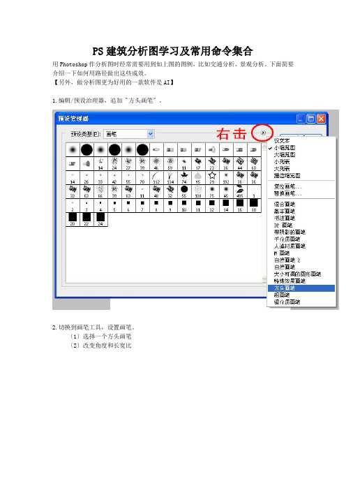
PS建筑分析图学习及常用命令集合用Photoshop作分析图时经常需要用到如上图的图例,比如交通分析、景观分析。
下面简要介绍一下如何用路径做出这些成效。
【另外,做分析图更为好用的一款软件是AI】1.编辑/预设治理器,追加〝方头画笔〞。
2.切换到画笔工具,设置画笔。
〔1〕选择一个方头画笔〔2〕改变角度和长宽比(3) 调整间距〔4〕切换到〝形状动态〞,将〝角度抖动〞切换到〝方向〞模式。
3.画路径〔1〕-〔2〕选择钢笔路径或形状工具,画出圆形或曲线路径。
〔右击〔2〕还有专门多其他形状,比如你将会用到的箭头〕〔3〕注意要在该状态下才能画出路径,否那么路径将被填充〔箭头就需要这种成效〕。
画好路径后,在路径面板中选择需要的路径图层,单击右键,选择〝描边路径〞。
在弹出的对话框中选择〝画笔〞,确定。
点击路径面板的空白处,取消激活〝路径1〞路径的黑线就不见了,即的到需要的图案。
【转】住宅小区如何做分析图刁刁001公司的分析图差不多上全部被我霸占了,俨然成了分析图专业户呵呵,做了这么多次做一下总结以便后日有用。
小区分析图1.张数可多可少2.内容可繁可简要看是处于什么样的时期和面对什么样的甲方。
假如是方案竞标之类的就能够做的花哨一点,我们公司一样差不多上托付项目,因此分析图做的比较简单一些然而麻雀虽小五脏俱全一些差不多的项依旧要有的,且在做的时候才发觉真是做的越细越感受自己明白的太少。
几轮下来按照作图的方便,分析图一样有以下几项〔有时候排序会依照图面的成效〕1. 人行流线分析图 2. 车行流线分析图 3. 消防分析图 4. 竖向分析图 5. 景观分析图 6. 日照分析图7. 户型分布图具体内容如下:1. 人行流线分析图。
那个比较简单一样包括A小区出入口:一样为2~3个,不宜多如此方便治理且此出入口不包括消防用的紧急出入口紧急出入口平常是不开放的。
B市政路为小区周围已建成的或者规划好的由政府来建设的道路〔因此具体实施起来可由开发商跟政府共同和谐建设〕那个甲方提供的地势图上一样会有直截了当标出即可。
最新PS抠图方法技巧大集合
PS抠图方法、技巧大集合一、魔术棒法——最直观的方法适用范围:图像和背景色色差明显,背景色单一,图像边界清晰。
方法意图:通过删除背景色来获取图像。
方法缺陷:对散乱的毛发没有用。
使用方法:1、点击“魔术棒”工具;2、在“魔术棒”工具条中,在“连续”项前打勾;3、“容差”值填入“20”。
(值可以看之后的效果好坏进行调节);4、用魔术棒点背景色,会出现虚框围住背景色;5、如果对虚框的范围不满意,可以先按CTRL+D取消虚框,再对上一步的“容差”值进行调节;6、如果对虚框范围满意,按键盘上的DELE键,删除背景色,就得到了单一的图像。
二、色彩范围法——快速适用范围:图像和背景色色差明显,背景色单一,图像中无背景色。
方法意图:通过背景色来抠图。
方法缺陷:对图像中带有背景色的不适用。
使用方法:1、颜色吸管拾取背景色;2、点击菜单中“选择”功能里的“色彩范围”功能;3、在“反相”项前打勾,确定后就选中图像了。
三、磁性索套法——方便、精确、快速和我常用的方法适用范围:图像边界清晰。
方法意图:磁性索套会自动识别图像边界,并自动黏附在图像边界上。
方法缺陷:边界模糊处需仔细放置边界点。
使用方法:1、右击“索套”工具,选中“磁性索套”工具;2、用“磁性索套”工具,沿着图像边界放置边界点,两点之间会自动产生一条线,并黏附在图像边界上。
3、边界模糊处需仔细放置边界点。
4、索套闭合后,抠图就完成了。
四、(索套)羽化法——粗加工适用范围:粗略的抠图。
方法意图:粗略抠图,不求精确。
方法缺陷:图像边界不精确。
使用方法:1、点击“索套”工具;2、用索套粗略地围住图像,边框各处要与图像边界有差不多的距离;这点能保证之后羽化范围的一致性,提高抠图的精确性;3、右击鼠标,选择“羽化”功能;4、调节羽化值,一般填入“20”,确定后就粗略选中图像了。
羽化值的大小,要根据前一步边框与图像的间距大小调节。
五、(索套)钢笔工具法——最精确最花工夫的方法适用范围:图像边界复杂,不连续,加工精度度高。
ps shortcut
Shift+工具——应用在选取工具中,当按住并拖动鼠标时按下SHIFT键,可选出正方形/圆形的选区。
Alt+工具——应用在选取工具中,按下ALT键,选区是一个以鼠标按下时的位置为中心的选取区域。
Shift+工具(已存在选区)——应用在选取工具中,当存在一个选取区域后,按下SHIFT可再加入另一选区。
Alt+工具(已存在选区)——应用在选取工具中,按下ALT可从原选区中减去目前选定的区域。
Ctrl+工具——当存在一个选区后,按下CTRL(光标变成剪刀)的同时按下鼠标并拖动可剪出区域移至别的地方。
Ctrl+Alt+工具——当按下CTRL+ALT(光标变成双箭头)的同时按下鼠标并拖动可复制区域移至别的地方。(此方式适用于除手指工具和钢笔工具外的所有工具)
14.按Tab键可以显示或隐藏工具箱和调板,按shift+tab键可以显示或隐藏除工具箱外的其它调板.
15.使用绘画工具进(如画笔,向笔等),按住shift键单击鼠标,可将两次单击点以直线连接.
16.使用路径工具时的几个技巧:使用钢笔工具制作路径时按住shift键可以强制路径或方向线成水平,垂直或45度角,按住ctrl键可暂进切到转换点工具,按住alt键可暂时切奂到转换点工具,按住alt键用直接选择工具单击某一路个路径可以按住shift键后逐个单击,按住ctrl+alt键拖动某一路径会将该路径复制.
2.按住Alt键后再单击显示的工具图标,或者按住shift键并重复按字母快捷键可以循环选择隐藏的工具.
3.双击某一工具或选择工具后按Enter键显示其选项调板.
4.按Caps Lock键会使画笔和磁性工具的光标显示为精确十字线,再按一次可恢复原状.
ps快捷键集合

只调整黄色(在色相/饱和度”对话框中) 【Ctrl】+【2】
只调整绿色(在色相/饱和度”对话框中) 【Ctrl】+【3】
只调整青色(在色相/饱和度”对话框中) 【Ctrl】+【4】
只调整蓝色(在色相/饱和度”对话框中) 【Ctrl】+【5】
像皮擦工具 【E】
铅笔、直线工具 【N】
模糊、锐化、涂抹工具 【R】
减淡、加深、海棉工具 【O】
钢笔、自由钢笔、磁性钢笔 【P】
添加锚点工具 【+】
删除锚点工具 【-】
直接选取工具 【A】
文字、文字蒙板、直排文字、直排文字蒙板 【T】
度量工具 【U】
直线渐变、径向渐变、对称渐变、角度渐变、菱形渐变 【G】
设置“存储文件”(在预置对话框中) 【Ctrl】+【2】
设置“显示和光标”(在预置对话框中) 【Ctrl】+【3】
设置“透明区域与色域”(在预置对话框中) 【Ctrl】+【4】
设置“单位与标尺”(在预置对话框中) 【Ctrl】+【5】
设置“参考线与网格”(在预置对话框中) 【Ctrl】+【6】
盖印可见图层 【Ctrl】+【Alt】+【Shift】+【E】
将当前层下移一层 【Ctrl】+【[】
将当前层上移一层 【Ctrl】+【]】
将当前层移到最下面 【Ctrl】+【Shift】+【[】
将当前层移到最上面 【Ctrl】+【Shift】+【]】
《ps界面介绍》课件

选择工具
矩形选择工具
用于选择矩形区域,包 括矩形选框和椭圆选框
。
套索选择工具
用于选择不规则形状的 区域。
快速选择工具
通过拖动快速选择相似 颜色或形状的区域。
裁剪工具
用于裁剪图片或调整图 片大小。
裁剪与切片工具
01
02
03
裁剪工具
通过裁剪图片来突出重点 或调整构图。
切片工具
将图片切割成多个部分, 便于分别编辑或导出。
用于替换图片中的特定颜色。
铅笔工具
模拟真实铅笔效果,适用于绘制直线或曲线 。
历史记录画笔工具
恢复图片到之前的状态,类似于历史记录功 能。
文字工具
横排文字工具
用于在图片中添加横排文 字。
直排文字工具
用于在图片中添加直排文 字。
文字蒙版工具
创建一个文字形状的选区 ,用于添加文字或进行其 他编辑操作。
04
保存图片
选择“文件”菜单中的“保存” 选项,在弹出的保存对话框中选 择要保存的位置和文件名,选择 合适的格式,点击“保存”。
裁剪与调整图片大小
裁剪图片
选择工具箱中的“裁剪工具”,在图 片上拖拽出裁剪区域,调整裁剪框的 大小和位置,完成后按Enter键确认 。
调整图片大小
选择工具箱中的“图像大小”工具, 在弹出的对话框中输入新的宽度和高 度,按Enter键确认。
课程目标
掌握Photoshop界面 基本构成和布局
学会高效利用 Photoshop界面进行 图像处理和设计工作
熟悉菜单栏、工具箱 、面板等主要功能区 域的使用方法
02
Photoshop界面概览
菜单栏
文件
用于打开、保存、导入和导出文 件等操作。
TPS54550PWPRG4资料
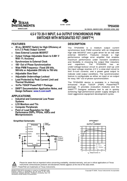
6,4 mm 55,0 mmFEATURES DESCRIPTIONAPPLICATIONSI- Output Current -AOEfficiency-%EFFICIENCYvsOUTPUT CURRENTSimplified SchematicTPS54550SLVS623A–MARCH2006–REVISED APRIL20064.5-V TO20-V INPUT,6-A OUTPUT SYNCHRONOUS PWMSWITCHER WITH INTEGRATED FET(SWIFT™)•40mΩMOSFET Switch for High Efficiency at The TPS54550is a medium output current 6-A(7.5Peak)Output Current synchronous buck PWM converter with an integratedhigh side MOSFET and a gate driver for an low side •Uses External Lowside MOSFETexternal MOSFET.Features include a high •Output Voltage Adjustable Down to0.891Vperformance voltage error amplifier that enables With1%Accuracy maximum performance under transient conditions•Synchronizes to External Clock and flexibility in choosing the output filter inductorsand capacitors.The TPS54550has an •180°Out of Phase Synchronizationunder-voltage-lockout circuit to prevent start-up until •Wide PWM Frequency–Fixed250kHz,the input voltage reaches4.5V;a slow-start circuit to500kHz or Adjustable250kHz to700kHz limit in-rush currents;and a power good output to •Adjustable Slow Start indicate valid output conditions.The synchronizationfeature is configurable as either an input or an output •Adjustable Undervoltage Lockoutfor easy180°out of phase synchronization.•Load Protected by Peak Current Limit andThe TPS54550device is available in a thermally Thermal Shutdownenhanced16-pin TSSOP(PWP)PowerPAD™•16-Pin TSSOP PowerPAD™Packagepackage.TI provides evaluation modules and the •SWIFT Documentation Application Notes,and SWIFT™Designer software tool to aid in quickly Design Software:/swift achieving high-performance power supply designs tomeet aggressive equipment development cycles.•Industrial and Commercial Low PowerSystems•LCD Monitors and TVs•Computer Peripherals•Point of Load Regulation for HighPerformance DSPs,FPGAs,ASICs andMicroprocessorsPlease be aware that an important notice concerning availability,standard warranty,and use in critical applications of TexasInstruments semiconductor products and disclaimers thereto appears at the end of this data sheet.SWIFT,PowerPAD are trademarks of Texas Instruments.PRODUCTION DATA information is current as of publication date.Copyright©2006,Texas Instruments Incorporated Products conform to specifications per the terms of the TexasInstruments standard warranty.Production processing does notnecessarily include testing of all parameters.PACKAGE DISSIPATION RATINGS (1)TPS54550SLVS623A–MARCH 2006–REVISED APRIL 2006These devices have limited built-in ESD protection.The leads should be shorted together or the device placed in conductive foam during storage or handling to prevent electrostatic damage to the MOS gates.ORDERING INFORMATIONT jOUTPUT VOLTAGE PACKAGE PART NUMBER (1)-40°C to 125°CAdjustable to 0.891VPlastic HTSSOP (PWP)TPS54550PWP (2)(1)For the most current package and ordering information,see the Package Option Addendum at the end of this document,or see the TI website at .(2)The PWP package is also available taped and reeled.Add an R suffix to the device type (i.e.,TPS54550PWPR).THERMAL IMPEDANCE T A =25°C T A =70°C T A =85°C PACKAGEJUNCTION-TO-AMBIENTPOWER RATINGPOWER RATINGPOWER RATING16-Pin PWP with solder (2)40.1°C/W2.491.371.00(1)See Figure 22for power dissipation curves.(2)Test Board Conditions a.3inch x 3inchb.Thickness:0.062inchc.2PCB layersd.2oz.Coppere.See Figure 26,Figure 27and TPS54550evaluation module user's guide for layout suggestions.2Submit Documentation FeedbackABSOLUTE MAXIMUM RATINGSELECTROSTATIC DISCHARGE RECOMMENDED OPERATING CONDITIONSTPS54550 SLVS623A–MARCH2006–REVISED APRIL2006over operating free-air temperature range unless otherwise noted(1)UNITVIN-0.3V to21.5VVSENSE-0.3V to8.0VUVLO-0.3V to8.0VV I Input voltage rangeSYNC-0.3V to4.0VSSENA-0.3V to4.0VBOOT VI(PH)+8.0VVBIAS-0.3to8.5VLSG-0.3to8.5VSYNC-0.3to4.0VV O Output voltage range RT-0.3to4.0VPWRGD-0.3to6.0VCOMP-0.3to4.0VPH-1.5V to22VPH Internally Limited(A)I O Source current LSG(Steady State Current)10mACOMP,VBIAS3mASYNC5mALSG(Steady State Current)100mAI S Sink current,PH(Steady State Current)500mACOMP3mASSENA,PWRGD10mA Voltage differential AGND to PGND±0.3VT J Junction temperature+150°CT stg Storage temperature-65°C to+150°C Lead temperature1,6mm(1/16inch)from case for10seconds260°C(1)Stresses beyond those listed under absolute maximum ratings may cause permanent damage to the device.These are stress ratingsonly,and functional operation of the device at these or any other conditions beyond those indicated under recommended operating conditions is not implied.Exposure to absolute-maximum-rated conditions for extended periods may affect device reliability.MIN TYP MAX UNIT Human Body Model HBM JESD22-A114 1.5kV Charged Device Model CDM JESD22-C101 1.5kVMIN NOM MAX UNIT V I Input voltage range 4.520VT J Operating junction temperature-40125°C3Submit Documentation FeedbackELECTRICAL CHARACTERISTICSTPS54550SLVS623A–MARCH 2006–REVISED APRIL 2006T J =-40°C to 125°C,VIN =4.5V to 20V (unless otherwise noted)PARAMETERTEST CONDITIOINSMIN TYP MAX UNITSUPPLY CURRENT Operating Current,PH pin open,10.3mA No external low side MOSFET,RT =Hi-Z I QQuiescent current Shutdown,SSENA =0V1.1mA Start threshold voltage4.324.49V VINStop threshold voltage 3.693.97V Hysteresis350mV UNDER VOLTAGE LOCK OUT (UVLO PIN)Start threshold voltage1.201.24V UVLOStop threshold voltage 1.021.10V Hysteresis100mVBIAS VOLTAGE (VBIAS PIN)I VBIAS =1mA,VIN ≥12V 7.57.88.0VBIASOutput voltageVI VBIAS =1mA,VIN =4.5V 4.4 4.47 4.5REFERENCE SYSTEM ACCURACYT J =25°C0.8880.8910.894V Reference voltage0.8820.8910.899VOSCILLATOR (RT PIN)RT Grounded 200250300Internally set PWM switching frequency kHz RT Open400500600Externally set PWM switching frequency RT =100k Ω(1%resistor to AGND)425500575kHz FALLING EDGE TRIGGERED BIDIRECTIONAL SYNC SYSTEM (SYNC PIN)SYNC out low-to-high rise time (10%/90%)(1)25pF to ground 200500ns SYNC out high-to-low fall time (90%/10%)(1)25pF to ground510ns Delay from rising edge to rising edge of Falling edge delay time (1)180°PH pins Minimum input pulsewidth (1)RT =100k Ω100ns Delay (falling edge SYNC to rising edge PH)(1)RT =100k Ω360ns 50k Ωresistor to ground,SYNC out high level voltage 2.5V No pullup resistorSYNC out low level voltage 0.6V SYNC in low level threshold 0.8V SYNC in high level threshold 2.3V Percentage of programmed frequency-10%10%SYNC in frequency range (1)225770kHz FEED-FORWARD MODULATOR (INTERNAL SIGNAL)Modulator gainVIN =12V,T J =25°C8V/VModulator gain variation -25%25%Minimum controllable ON time (1)180nsMaximum duty factor (1)VIN =4.5V80%86%ERROR AMPLIFIER (VSENSE and COMP PINS)Error amplifier open loop voltage gain (1)6080dB Error amplifier unity gain bandwidth (1) 1.02.8MHz Input bias current,VSENSE pin500nA COMPOutput voltage slew rate (symmetric)(1)1.5V/µs (1)Specified by design,not production tested.4Submit Documentation FeedbackTPS54550 SLVS623A–MARCH2006–REVISED APRIL2006ELECTRICAL CHARACTERISTICS(continued)T J=-40°C to125°C,VIN=4.5V to20V(unless otherwise noted)PARAMETER TEST CONDITIOINS MIN TYP MAX UNIT Slow Start/ENABLE(SSENA PIN)Disable low level input voltage0.5Vf s=250kHz,RT=ground(2) 4.6Internal slow-start time(10%to90%)msf s=500kHz,RT=Hi-Z(2) 2.3Pullup current source 1.8510µAPulldown MOSFET II(SSENA)=1mA0.1V POWER GOOD(PWRGD PIN)Power good threshold Rising voltage97%f s=250kHz4Rising edge delay(2)msf s=500kHz2Output saturation voltage I sink=1mA,VIN>4.5V0.05V PWRGD Output saturation voltage I sink=100µA,VIN=0V0.76V Open drain leakage current Voltage on PWRGD=6V3µA CURRENT LIMITCurrent limit VIN=12V7.58.59.5ACurrent limit Hiccup Time(2)f s=500kHz 4.5ms THERMAL SHUTDOWNThermal shutdown trip point165°CThermal shutdown hysteresis(2)7°C LOW SIDE MOSFET DRIVER(LSG PIN)VIN=4.5V,Capacitive load=1000pF15 Turn on rise time,(10%/90%)(2)nsVIN=8V,Capacitive load=1000pF12 Deadtime(2)VIN=12V60nsVIN=4.5V sink/source7.5 Driver ON resistanceΩVIN=12V sink/source5OUTPUT POWER MOSFETS(PH PIN)Phase node voltage when disabled DC conditions and no load,SSENA=0V0.5VVIN=4.5V,Idc=100mA 1.13 1.42 Voltage drop,low side FET and diode VVIN=12V,Idc=100mA 1.08 1.38VIN=4.5V,BOOT-PH=4.5V,I O=0.5A60r DS(ON)High side power MOSFET switch(3)mΩVIN=12V,BOOT-PH=8V,I O=0.5A40(2)Specified by design,not production tested.(3)Resistance from VIN to PH pins.5Submit Documentation FeedbackPIN ASSIGNMENTSVIN VIN UVLO PWRGDRT SYNC SSENA COMPBOOT PH PH LSG VBIAS PGND AGND VSENSEPWP PACKAGE (TOP VIEW)NOTE:If there is not a Pin 1 indicator, turn device to enable reading the symbol from left to right. Pin 1 is at the lower left corner of the device.TPS54550SLVS623A–MARCH 2006–REVISED APRIL 2006Terminal FunctionsTERMINAL DESCRIPTION 1,2VIN Input supply voltage,4.5V to 20V.Must bypass with a low ESR 10-µF ceramic capacitor.3UVLO Undervoltage lockout pin.Connecting an external resistive voltage divider from VIN to the pin will override the internal default VIN start and stop thresholds.4PWRGD Power good output.Open drain output.A low on the pin indicates that the output is less than the desired output voltage.There is an internal rising edge filter on the output of the PWRGD comparator.5RT Frequency setting pin.Connect a resistor from RT to AGND to set the switching frequency.Connecting the RT pin to ground or floating will set the frequency to an internally preselected frequency.6SYNCBidirectional synchronization I/O pin.SYNC pin is an output when the RT pin is floating or connected low.The output is a falling edge signal out of phase with the rising edge of PH.SYNC may be used as an input tosynchronize to a system clock by connecting to a falling edge signal when an RT resistor is used.See 180°Out of Phase Synchronization operation in the Application Information section.7SSENASlow Start/Enable.The SSENA pin is a dual function pin which provides a logic enable/disable and a slow start time set.Below 0.5V,the device stops switching.Float pin to enable.Capacitor to ground adjusts the slow start time.See Extending Slow Start Time section.8COMP Error amplifier output.Connect frequency compensation network from COMP to VSENSE pins.9VSENSE Inverting node error amplifier.10AGND Analog ground—internally connected to the sensitive analog ground circuitry.Connect to PGND and PowerPAD.11PGND Power Ground—Noisy internal ground—Return currents from the LSG driver output return through the PGND pin.Connect to AGND and PowerPAD.12VBIAS Internal 8.0V bias voltage.A 1.0µF ceramic bypass capacitance is required on the VBIAS pin.13LSG Gate drive for low side MOSFET.Connect gate of n-channel MOSFET.14,15PH Phase node—Connect to external L-C filter.16BOOT Bootstrap for high side gate driver.Connect 24Ohm and 0.1µF ceramic capacitor from BOOT to PH pins.17PowerPADPGND and AGND pins must be connected to the exposed pad for proper operation.See Figure 26for an example PCB layout.6Submit Documentation FeedbackFUNCTIONAL BLOCK DIAGRAMPHLSGPWRGDAGNDPGNDVBIASPOWERPADTPS54550SLVS623A–MARCH 2006–REVISED APRIL 20067Submit Documentation FeedbackDETAILED DESCRIPTIONUndervoltage Lockout(UVLO)Slow Start Enable(SSENA)and Internal SlowT SS_INTERNAL(ms) 1.15kƒs(kHz)(3)Input Voltage SupplyExtending Slow Start TimeR1 VIN(start)1k p1.24V)1k p(1)VIN(stop) (R1)1k p) 1.02V1k p(2)TPS54550SLVS623A–MARCH2006–REVISED APRIL2006StartThe undervoltage lockout(UVLO)system has aninternal voltage divider from VIN to AGND.The Once the SSENA pin voltage exceeds0.5V,the defaults for the start/stop values are labeled VIN and TPS54550starts operation.The TPS54550has an given in Table1.The internal UVLO threshold can be internal digital slow start that ramps the reference overridden by placing an external resistor divider from voltage to its final value in1150switching cycles.The VIN to ground.The internal divider values are internal slow start time(10%-90%)is approximated approximately320kΩfor the high side resistor and by the following expression:125kΩfor the low side resistor.The divider ratio(andtherefore the default start/stop values)is quiteaccurate,but the absolute values of the internalresistors may vary as much as15%.If high accuracy Once the TPS54550device is in normal regulation, is required for an externally adjusted UVLO threshold,the SSENA pin is high.If the SSENA pin is pulled select lower value external resistors to set the UVLO below the stop threshold of0.5V,switching stops ing a1-kΩresistor for the low side and the internal slow start resets.If an application resistor R2(see Figure1)is recommended.Under no requires the TPS54550to be disabled,use open circumstances should the UVLO pin be connected drain or open collector output logic to interface to the directly to VIN.SSENA pin(see Figure2).The SSENA pin has aninternal pullup current source.Do not use external Table1.Start/Stop Voltage Threshold pullup resistors.START VOLTAGE STOP VOLTAGETHRESHOLD THRESHOLDVIN(Default) 4.49 3.69UVLO 1.24 1.02Figure2.Interfacing to the SSENA Pin Figure1.Circuit Using External UVLO FunctionThe equations for selecting the UVLO resistors are:In applications that use large values of outputcapacitance there may be a need to extend the slowstart time to prevent the startup current from trippingthe current limit.The current limit circuit is designedto disable the high side MOSFET and reset theinternal voltage reference for a short amount of time For applications which require an undervoltage lockwhen the high side MOSFET current exceeds the out(UVLO)threshold greater than4.49V,externalcurrent limit threshold.If the output capacitance and resistors may be implemented,see Figure1,to adjustload current cause the startup current to exceed the the start voltage threshold.For example,ancurrent limit threshold,the power supply output will application needing an UVLO start voltage ofnot reach the desired output voltage.To extend the approximately7.8V using the equation(1),R1isslow start time and to reduce the startup current,an calculated to the nearest standard resistor value ofexternal capacitor can be added to the SSENA pin.5.36kΩ.Using Equation2,the input voltage stopThe slow start capacitance is calculated using the threshold is calculated as6.48V.following equation:C SS(µF)=5.55x10⁻³T ss(ms)8Submit Documentation FeedbackSwitching Frequency(RT)RT(k p)46000ƒs(kHz)–35.9(4)V I(SYNC) V O(PH)TPS54550 SLVS623A–MARCH2006–REVISED APRIL2006The TPS54550has an internal oscillator thatoperates at twice the PWM switching frequency.TheThe RT pin controls the SYNC pin functions.If the RT internal oscillator frequency is controlled by the RTpin is floating or grounded,SYNC is an output.If the pin.Grounding the RT pin sets the PWM switchingswitching frequency has been programmed using a frequency to a default frequency of250kHz.Floatingresistor from RT to AGND,then SYNC functions as the RT pin sets the PWM switching frequency toan input.500kHz.The internal voltage ramp charging current increases Connecting a resistor from RT to AGND sets thelinearly with the set frequency and keeps the feed frequency according to Equation4(see Figure13).forward modulator constant(Km=8)regardless ofthe frequency set point.Table2.Switching Frequency,SYNC and RT PinsSWITCHING FREQUENCY SYNC PIN RT PIN250kHz,internally set Generates SYNC output signal AGND500kHz,internally set Generates SYNC output signal Float Externally set to250kHz to700kHz Terminate to quiet ground with10-kΩR=215kΩto69kΩresistor.Externally synchronized frequency Synchronization Signal Use110kΩwhen RT floats and237kΩwhen RT isgrounded and using the sync out signal of anotherTPS54550.Set RT resistor equal to90%to110%ofexternal synchronization frequency.180°Out of Phase Synchronization(SYNC)When operating the two TPS54550devices180°outof phase,the total RMS input current is reduced. The SYNC pin is configurable as an input or as an Thus reducing the amount of input capacitance output,per the description in the previous section.needed and increasing efficiency.When operating as an input,the SYNC pin is afalling-edge triggered signal(see Figure3and When synchronizing a TPS54550to an external Figure4).When operating as an output,the signal's signal,the timing resistor on the RT pin must be set falling edge is approximately180°out of phase with so that the oscillator is programmed to run at90%to the rising edge of the PH pins.Thus,two TPS54550110%of the synchronization frequency.devices operating in a system can share an inputNOTE:Do not use synchronization input for designs capacitor and draw ripple current at twice thewith output voltages>10V.frequency of a single unit.Figure3.SYNC Input Waveform9Submit Documentation FeedbackInternal OscillatorV O(PH)V O(SYNC)Power Good (PWRGD)Bootstrap Voltage (BOOT)Error AmplifierVoltage ReferenceT delay 1000ƒs(kHz)ms (5)Bias Voltage (VBIAS)TPS54550SLVS623A–MARCH 2006–REVISED APRIL 2006Figure 4.SYNC Output WaveformUp to 1mA of current can be drawn for use in anexternal application circuit.The VBIAS pin must have a bypass capacitor value of 1.0µF.X7R or X5R The VSENSE pin is compared to an internal grade dielectric ceramic capacitors are recommended reference signal,if the VSENSE is greater than 97%because of their stable characteristics over and no other faults are present,the PWRGD pin temperature.presents a high impedance.A low on the PWRGD pin indicates a fault.The PWRGD pin has been designed to provide a weak pull-down and indicates a fault even when the device is unpowered.If the TPS54550The BOOT capacitor obtains its charge cycle by cycle has power and has any fault flag set,the TPS54550from the VBIAS capacitor.A capacitor and small indicates the power is not good by driving the value resistor from the BOOT pin to the PH pins is PWRGD pin low.The following events,singly or in required for operation.The bootstrap connection for combination,indicate power is not good:the high side driver must have a bypass capacitor of 0.1µF and resistor 24Ohm.•VSENSE pin out of bounds •Overcurrent•Thermal shutdown The VSENSE pin is the error amplifier inverting input.•UVLO undervoltageThe error amplifier is a true voltage amplifier with 1.5•Input voltage not present (weak pull-down)mA of drive capability with a minimum of 60dB of •Slow-startingopen loop voltage gain and a unity gain bandwidth of •VBIAS voltage is low2MHz.Once the PWRGD pin presents a high impedance (i.e.,power is good),a VSENSE pin out of bounds condition forces PWRGD pin low (i.e.,power is bad)The voltage reference system produces a precision after a time delay.This time delay is a function of the reference signal by scaling the output of a switching frequency and is calculated using temperature stable bandgap circuit.During production Equation 5:testing,the bandgap and scaling circuits are trimmed to produce 0.891V at the output of the error amplifier,with the amplifier connected as a voltage follower.The trim procedure improves the regulation,since it cancels offset errors in the scaling and error amplifier circuits.The VBIAS regulator provides a stable supply for the internal analog circuits and the low side gate driver.10Submit Documentation FeedbackPWM Control and Feed ForwardDeadtime ControlLow Side Gate Driver(LSG)Thermal Shutdown TPS54550SLVS623A–MARCH2006–REVISED APRIL2006reference ramps from0V to0.891V.During theinitial slow-start interval,the internal reference voltage Signals from the error amplifier output,oscillator,and is very small resulting in a couple of skipped pulses current limit circuit are processed by the PWM control because the minimum on time causes the actual logic.Referring to the internal block diagram,the output voltage to be slightly greater than the preset control logic includes the PWM comparator,PWM output voltage until the internal reference ramps up. latch,and the adaptive dead-time control logic.During steady-state operation below the current limitthreshold,the PWM comparator output and oscillatorpulse train alternately reset and set the PWM latch.Adaptive dead time control prevents shoot throughcurrent from flowing in the integrated high-side Once the PWM latch is reset,the low-side driver andMOSFET and the external low-side MOSFET during integrated pull-down MOSFET remain on for athe switching transitions by actively controlling the minimum duration set by the oscillator pulse width.turn on times of the drivers.The high-side driver does During this period,the PWM ramp discharges rapidlynot turn on until the voltage at the gate of the to the valley voltage.When the ramp begins tolow-side MOSFET is below1V.The low-side driver charge back up,the low-side driver turns off and thedoes not turn on until the voltage at the gate of the high-side FET turns on.The peak PWM ramp voltagehigh-side MOSFET is below1V.varies inversely with input voltage to maintain aconstant modulator and power stage gain of8V/V.As the PWM ramp voltage exceeds the error amplifierLSG is the output of the low-side gate driver.The output voltage,the PWM comparator resets the latch,100-mA MOSFET driver is capable of providing gate thus turning off the high-side FET and turning on thedrive for most popular MOSFETs suitable for this low-side FET.The low-side driver remains on untile the SWIFT Designer Software Tool the next oscillator pulse discharges the PWM ramp.to find the most appropriate MOSFET for the During transient conditions,the error amplifier output application.Connect the LSG pin directly to the gate can be below the PWM ramp valley voltage or above of the low-side MOSFET.Do not use a gate resistor the PWM peak voltage.If the error amplifier is high,as the resulting turn-on time may be too slow.the PWM latch is never reset and the high-side FETremains on until the oscillator pulse signals thecontrol logic to turn the high-side FET off and theThe device uses the thermal shutdown to turn off the internal low-side FET and driver on.The deviceMOSFET drivers and controller if the junction operates at its maximum duty cycle until the outputtemperature exceeds165°C.The device is restarted voltage rises to the regulation set point,settingautomatically when the junction temperature VSENSE to approximately the same voltage as thedecreases to7°C below the thermal shutdown trip internal voltage reference.If the error amplifier outputpoint and starts up under control of the slow-start is low,the PWM latch is continually reset and thecircuit.high-side FET does not turn on.The internal low-sideFET and low side driver remain on until the VSENSEvoltage decreases to a range that allows the PWMcomparator to change states.The TPS54550iscapable of sinking current through the external lowside FET until the output voltage reaches theregulation set point.The minimum on time is designed to be180ns.During the internal slow-start interval,the internalOvercurrent ProtectionOutput Voltage LimitationsT HICCUP(ms) 2250ƒs(kHz)(6)Setting the Output VoltageR2 R1 0.891V O )0.891(7)TPS54550SLVS623A–MARCH 2006–REVISED APRIL 2006OUTPUT VOLTAGE (V)R2VALUE (k Ω)1.228.7Overcurrent protection is implemented by sensing the 1.514.7drain-to-source voltage across the high-side 1.89.76MOSFET and compared to a voltage level which represents the overcurrent threshold limit.If the2.5 5.49drain-to-source voltage exceeds the overcurrent3.33.74threshold limit for more than 100ns,the high-side MOSFET is disable,the SSENA pin is pulled low,and the internal digital slow-start is reset to 0V.SSENA is held low for approximately the time that is calculated Due to the internal design of the TPS54550there are by Equation 6:both upper and lower output voltage limits for any given input voltage.Additionally,the lower boundary of the output voltage set point range is also dependent on operating frequency.The upper limit of the output voltage set point is constrained by the Once the hiccup time is complete,the SSENA pin ismaximum duty cycle of the device and is shown in released and the converter initiates the internal Figure 12.The lower limit is constrained by the slow-start.minimum controllable on time which may be as high as 220ns.The approximate minimum output voltage for a given input voltage and range of operating The output voltage of the TPS54550can be set by frequencies is shown in Figure 8while the maximum feeding back a portion of the output to the VSENSE operating frequency versus input voltage for some pin using a resistor divider network.In the application common output voltages is shown in Figure 10.circuit of Figure 29,this divider network is comprised The curves shown in these two figures are valid for of resistors R1and R2.To calculate the resistor output currents greater than 0.5A.As output currents values to generate the required output voltage use decrease towards no load (0A),the minimum output the following equation:voltage decreases.For applications where the load current is less than 100mA,the curves shown in Figure 9and Figure 11are applicable.All of the data plotted in these curves are approximate and take into Start with a fixed value of R1and calculate theaccount a possible 20percent deviation in actual required R2value.Assuming a fixed value of 10k Ωoperating frequency relative to the intended set point.for R1,the following table gives the appropriate R2value for several common output voltages:TYPICAL CHARACTERISTICS0102030405060708090T - Junction Temperature - °CJ O n R e s i s t a n c e - m W0.89120.89100.89080.89060.89040.89020.89000.8898−50−250255075100125150V r e f − I n t e r n a l V o l t a g e R e f e r e n ce − VT J − Junction Temperature − 5CV - Input Voltage - VI C u r r e n t L i m i t -AM i n i m u m O u t p u t V o l t a g e − VV I − Input Voltage − V100200300400500600700800M a x i m u m S w i t c h i n g F r e q u e n c y − k H zV I − Input Voltage − VM i n i m u m O u t p u t V o l t a g e − VV I − Input Voltage − VM a x i m u m S w i t c h i n g F r e q u e n c y − k H zV I − Input Voltage − V5075100125150175200225200300400500600700R T R e s i s t a n c e − k WSwitching Frequency − kHz02468101214510152025− O u t p u t V o l t a g e − VV O V I − Input Voltage − VTPS54550SLVS623A–MARCH 2006–REVISED APRIL 2006ON RESISTANCECURRENT LIMITINTERNAL VOLTAGE REFERENCEvsvsvsJUNCTION TEMPERATUREINPUT VOLTAGEJUNCTION TEMPERATUREFigure 5.Figure 6.Figure 7.MINIMUM OUTPUT VOLTAGEMINIMUM OUTPUT VOLTAGEMAXIMUM SWITCHING FREQUENCYvsvsvsINPUT VOLTAGEINPUT VOLTAGEINPUT VOLTAGEFigure 8.Figure 9.Figure 10.MAXIMUM SWITCHING FREQUENCYMAXIMUM OUTPUT VOLTAGERT RESISTANCEvsvsvsINPUT VOLTAGEINPUT VOLTAGESWITCHING FREQUENCYFigure 11.Figure 12.Figure 13.。
Photoshop CS3教程

Photoshop CS3(10.0版)一、软件界面简介:1.标题栏:显示软件名称、显示图像窗口信息及放置窗口控制图标。
1)窗口控制图标快捷键或快捷操作:(1)最小化:Windows+D(2)还原与最大化切换:双击标题栏(3)退出:Ctrl+Q或Alt+F42)多个软件窗口切换快捷键:Alt+Tab多个图像窗口切换快捷键:Ctrl+Tab2.菜单栏:集合软件所有的操作命令1)操作命令快捷键:(1)新建:Ctrl+N(新建一张空白的纸)提示:A4纸-Ctrl+N-预设中选国际标准纸张-大小中选A4-OK(尺寸:210×297mm,分辨率300)(2)关闭图像窗口:Ctrl+W(将打开的图像窗口关闭)(3)打开图像窗口:双击灰色软件背景或Ctrl+O(打开素材图片)(4)关闭多图像窗口:Ctrl+Alt+W (关闭多个素材图片窗口)(5)撤消操作:Ctrl+Z(可完成一次撤消或一次恢复)(6)多次撤消:Ctrl+Alt+Z(可完成多次撤消操作,默认最多20次,可更改)提示:Ctrl+K首选项-Ctrl+4性能-更改20次(7)多次恢复:Ctrl+Shift+Z(可完成多次恢复操作,默认最多20次,可更改)(8)存储:Ctrl+S(可将新建图像进行保存)(9)存储为:Ctrl+Shift+S(可将打开图像进行备份保存)(10)存储优化:Ctrl+Shift+Alt+S (可将图像存储优化Web所支持格式Jpg/Png/Gif)(11)打印:Ctrl+P(可将图像打印输出)(12)其它快捷键:a.Ctrl+Shift+Alt+O打开为:只针对于所选格式进行打开文件b.Ctrl+Shift+Alt+P只打印一份:打印时只打印一张c.F12恢复:可将编辑处理过的图像恢复到最近的一次存储状态(如没有存储状态存在,将恢复到最近一次打开状态)d.Ctrl+Shift+F渐隐:可将图像滤镜效果强度减弱,即透明不透明程度。
ps快捷键大全
ps快捷键大全在学习与使用Photoshop(简称PS)过程中,熟悉并运用快捷键是提高工作效率的关键。
本文将为您全面介绍PS中常用的快捷键大全,帮助您更加高效地使用PS软件。
一、常见快捷键1. 新建文件:Ctrl+N(Win)/Command+N(Mac)2. 打开文件:Ctrl+O(Win)/Command+O(Mac)3. 保存文件:Ctrl+S(Win)/Command+S(Mac)4. 撤销操作:Ctrl+Z(Win)/Command+Z(Mac)5. 重做操作:Ctrl+Shift+Z(Win)/Command+Shift+Z(Mac)6. 全屏显示:F键7. 移动画布:空格键+鼠标拖动8. 放大画布:Ctrl++(Win)/Command++(Mac)9. 缩小画布:Ctrl+-(Win)/Command+-(Mac)10. 还原画布缩放:Ctrl+0(Win)/Command+0(Mac)11. 复制选中区域:Ctrl+C(Win)/Command+C(Mac)12. 粘贴剪贴板内容:Ctrl+V(Win)/Command+V(Mac)13. 剪切选中区域:Ctrl+X(Win)/Command+X(Mac)14. 播放动画:Alt+Shift+Ctrl+Space(Win)/Option+Shift+Command+Space(Mac)15. 调出调整图层对话框:Ctrl+L(Win)/Command+L(Mac)16. 新建图层:Ctrl+Shift+N(Win)/Command+Shift+N(Mac)17. 合并图层:Ctrl+E(Win)/Command+E(Mac)18. 锁定图层透明度:/(斜杠键)19. 快速选择工具:W键20. 矩形选框工具:M键二、选区与裁剪1.新建选区:Ctrl+Shift+N(Win)/ Command+Shift+N(Mac)2.椭圆选框工具:E键3.套索工具:L键4.多边形套索工具:L键5.快速选择工具:W键6.魔棒工具:W键7.魔术橡皮擦工具:L键8.剪贴工具:C键9.图章工具:L键10.剪切工具:C键三、绘画与涂鸦1.画笔工具:B键2.油漆桶工具:G键3.选色工具:I键4.渐变工具:G键5.橡皮擦工具:E键6.修补工具:J键7.模糊工具:R键四、图层样式与文字1.图层样式对话框:Alt+Dbl点击图层缩略图2.图层样式:Ctrl+Alt+Shift+E(Win)/ Command+ Option+Shift+E (Mac)3.打开字符选项对话框:Alt+Ctrl+Shift+T(Win)/Option+Command+Shift+T(Mac)五、其他常用快捷键1.显示/隐藏参考线:Ctrl+;(Win)/Command+;(Mac)2.显示/隐藏网格:Ctrl+’(Win)/Comman d+’(Mac)3.查看实际像素:Ctrl+Alt+0(Win)/Option+Command+0(Mac)4.自动对焦图层:Ctrl+Alt+点击图层(Win)/Option+Command+点击图层(Mac)通过掌握以上快捷键,您可以更加高效地使用PS软件进行图像处理、设计和编辑。
ps贴图技巧
PS抠图方法、技巧大集合一、魔术棒法——最直观的方法适用范围:图像和背景色色差明显,背景色单一,图像边界清晰。
方法意图:通过删除背景色来获取图像。
方法缺陷:对散乱的毛发没有用。
使用方法:1、点击“魔术棒”工具;2、在“魔术棒”工具条中,在“连续”项前打勾;3、“容差”值填入“20”。
(值可以看之后的效果好坏进行调节);4、用魔术棒点背景色,会出现虚框围住背景色;5、如果对虚框的范围不满意,可以先按CTRL+D取消虚框,再对上一步的“容差”值进行调节;6、如果对虚框范围满意,按键盘上的DELE键,删除背景色,就得到了单一的图像。
二、色彩范围法——快速适用范围:图像和背景色色差明显,背景色单一,图像中无背景色。
方法意图:通过背景色来抠图。
方法缺陷:对图像中带有背景色的不适用。
使用方法:1、颜色吸管拾取背景色;2、点击菜单中“选择”功能里的“色彩范围”功能;3、在“反相”项前打勾,确定后就选中图像了。
三、磁性索套法——方便、精确、快速和我常用的方法适用范围:图像边界清晰。
方法意图:磁性索套会自动识别图像边界,并自动黏附在图像边界上。
方法缺陷:边界模糊处需仔细放置边界点。
使用方法:1、右击“索套”工具,选中“磁性索套”工具;2、用“磁性索套”工具,沿着图像边界放置边界点,两点之间会自动产生一条线,并黏附在图像边界上。
3、边界模糊处需仔细放置边界点。
4、索套闭合后,抠图就完成了。
四、(索套)羽化法——粗加工适用范围:粗略的抠图。
方法意图:粗略抠图,不求精确。
方法缺陷:图像边界不精确。
使用方法:1、点击“索套”工具;2、用索套粗略地围住图像,边框各处要与图像边界有差不多的距离;这点能保证之后羽化范围的一致性,提高抠图的精确性;3、右击鼠标,选择“羽化”功能;4、调节羽化值,一般填入“20”,确定后就粗略选中图像了。
羽化值的大小,要根据前一步边框与图像的间距大小调节。
五、(索套)钢笔工具法——最精确最花工夫的方法适用范围:图像边界复杂,不连续,加工精度度高。
Photoshop操作技巧(2010最新版)
PS经典教程1、教你打造偏色艺术色调教程2、 ·教你打造偏色艺术色调教程3、 Photoshop┾製造制造另类婚纱照片4、⒈款粉帥氣de游戲做圖5、 PS(IR)可爱的棒棒糖6、 ps打造唯美色调7、 PS打造超炫人物效果8、一款比较自然的眨眼教程9、 Photoshop最简易的磨皮法10、Photoshop] 制作下雨的效果11、小菱形背景和圆点背景的做法12、[Photoshop] PS打造淡彩风格的幻眼效果13、Photoshop] 用Photoshop滤镜打造梦幻艺术效果14、Photoshop] 巧用PS打造镶满诱人钻石的文字15、Photoshop] PS制作幽冥火焰16、Photoshop] 简单的叠影制作方法17、Photoshop] 制作冬季恋歌浪漫雪景效果18、Photoshop] 用Photoshop设计另类树皮人体19、Photoshop] 教你设计绚丽光芒效果20、Photoshop] 教你设计胶片风情电影海报21、Photoshop] 教你设计神秘炫光黑洞效果22、Photoshop] PS特效字:闪亮钻石效果23、[Photoshop] 巧绘晶莹剔透的水晶樱桃24、Fireworks] QQ空间初级玩家必学的11条技巧25、Flash] 给FLASH初学者的10点制作经验26、Flash] Flash全屏效果全攻略27、Photoshop] 利用PS图层样式绘制彩色玻璃立体文字28、Photoshop] Photoshop制作逼真的洁白羽毛29、Photoshop] 用PS把秋景照片变为冬景效果30、[Photoshop] Photoshop教你给MM的衣服换个颜色31、Photoshop] 用PS制作周迅的怀旧效果图32、Photoshop] 转用PS轻松给MM衣服添加图案33、Photoshop] 用PS的动态画笔制作鞭炮34、Photoshop] 教你做天使翅膀的卡通效果35、Photoshop] 制作融化的冰淇淋36、Photoshop] 打造宇宙场景爆炸星球特效37、Photoshop] 教你设计恐怖电影海报Photoshop] 制作奔驰中的汽车[Photoshop] 蝴蝶结边框[Photoshop] 印章制作小教程(ps新手适用)[Photoshop] Photoshop高级柔化处理人物照片Photoshop] 神奇的Photoshop修图美容--很实用[Photoshop] 简单PS教程--制作面部护肤化妆品Photos hop] ○简单的给黑白照片上色(适合新手)Photoshop] Photoshop用户必知必会的28个快捷键Photoshop] 用马赛克效果处理图片[Photoshop] 可爱歪框框Photoshop] 打造鬼屋效果教程Photoshop] 教你Ps滤镜巧绘蕾丝花边相框Photoshop] 制作撕纸效果Fireworks] FW坠子[Photoshop] 修补照片的一般方法(文字版) Fireworks] 象素娃娃的教程Fireworks] 图片燃烧边缘效果的制作Fireworks] 地震效果的制作(文字版)Fireworks] 旋转吊坠制作[Photoshop] 一根香烟的制作过程Photoshop] 让图片飘落樱花Photoshop] 让图片飘落樱花Photoshop] 让图片飘落樱花Fireworks] 教你一步一步绘制竹子[Fireworks] 教你做极光字。
Anl_RPS60_48V_EEC_01_0407_de_en
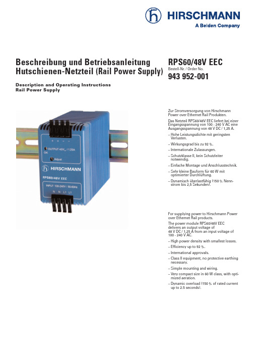
Beschreibung und Betriebsanleitung Hutschienen-Netzteil (Rail Power Supply)Description and Operating Instructions Rail Power SupplyRPS60/48V EEC Zur Stromversorgung von Hirschmann Power over Ethernet Rail Produkten.Das Netzteil RPS60/48V EECliefert bei einer Eingangsspannung von 100 - 240 V AC eine Ausgangsspannung von 48 V DC / 1,25 A.– Hohe Leistungsdichte mit geringsten Verlusten.– Wirkungsgrad bis zu 92 %.– Internationale Zulassungen.– Schutzklasse II, kein Schutzleiter notwendig.– Einfache Montage und Anschlusstechnik.– Sehr kleine Bauform für 60 W mit optimierter Durchlüftung.– Dynamisch überlastfähig (150 % Nenn-strom bis 2,5 Sekunden).For supplying power to Hirschmann Power over Ethernet Rail products.The power module RPS60/48V EEC delivers an output voltage of48 V DC / 1,25 A from an input voltage of 100 - 240 V AC .– High power density with smallest losses.– Efficiency up to 92 %.– International approvals.– Class II equipment, no protective earthing necessary.– Simple mounting and wiring.– Very compact size in 60 W class, with opti-mized aeration.– Dynamic overload (150 % of rated current up to 2.5 seconds).Bestell-Nr. / Order No.943 952-001Die beschriebenen Leistungsmerkmale sind nur dann verbindlich, wenn sie bei Vertragsschluß ausdrücklich vereinbart wurden. Wir haben den Inhalt der Druck-schrift auf Übereinstimmung mit der beschriebenen Hard- und Softwaregeprüft. Dennoch können Abweichungen nicht ausgeschlossen werden, so daß wir für die vollständige Übereinstimmung keine Gewähr übernehmen. Die Angaben in der Druckschrift werden jedoch regel-mäßig überprüft. Notwendige Korrekturen sind in den nachfolgenden Auflagen ent-halten. Für Verbesserungsvorschläge sind wir dankbar.Technische Änderungen vorbehalten. Weitergabe sowie Vervielfältigung dieser Unterlage, Verwertung und Mitteilung ihres Inhalts ist nicht gestattet, soweit nicht ausdrücklich zugestanden. Zuwider-handlungen verpflichten zu Schadenser-satz. Alle Rechte vorbehalten, insbesonde-re für den Fall der Patenterteilung oder GM-Eintragung.Copyright© HirschmannAutomation and Control GmbH2007All Rights Reserved Bestimmungsgemäßer GebrauchBitte beachten Sie folgendes:z Warnung!Das Gerät darf nur für die im Kata-log und in der technischenBeschreibung vorgesehenen Ein-satzfälle und nur in Verbindung mitvon Hirschmann empfohlenenbzw. zugelassenen Fremdgerätenund -komponenten verwendetwerden. Der einwandfreie undsichere Betrieb des Produktes setztsachgemäßen Transport, sach-gemäße Lagerung, Aufstellungund Montage sowie sorgfältigeBedienung und Instandhaltungvoraus.z Sicherheitshinweise– Anleitung lesen!Bevor Sie mit dem Netzteil arbeiten, lesen Sie diese Anleitung komplett durch. Stellen Sie sicher, daß Sie alles verstanden haben. Beachten Sie alle Hin-weise.– Inbetriebsetzen und Fehlerbehebung darf nur von einer Elektrofachkraft(lt. VDE 0100) durchgeführt werden. Schalten sie alle zu montierenden Anschlussleitungen spannungslos. Treffen sie Sicherheitsvorkehrungen gegen unbeabsichtigtes Einschalten.– Solange das Gerät in Betrieb ist, dürfen keinerlei Änderung an der Installation vorgenommen werden.– Die Anschlussklemmen nur spannungs-frei betätigen.– Die Lüftungsschlitze nicht verdecken.Über und unter den Geräten mindestens3cm Freiraum halten.Die Zulufttemperatur an der Geräteunter-seite darf die max. Betriebstemperaturnicht überschreiten (siehe Kapitel “Techni-sche Daten”).– Im Gerät befinden sich Bauteile und Leiter,die – auch im Fehlerfall – lebensgefährli-che Hochspannung speichern. Derunsachgemäße Gebrauch kann zu Strom-schlag oder schweren Verbrennungenführen.– Das Gerät darf nur von einer Elektrofach-kraft (lt. VDE 0100) frühestens 5 Minutennach allpoligem Abtrennen vom Netzgeöffnet werden.– Die interne Sicherung dient dem Geräte-schutz, sie darf nicht durch den Bedienerausgetauscht werden. Defekte Gerätemüssen aus Sicherheitsgründen zum Her-steller geschickt werden.– Für den Einsatz in Ex-Anwendungenbeachten Sie die Hinweise in Kapitel“Technische Daten”.7Hinweis zurCE-KennzeichnungDie Geräte stimmen mit den Vor-schriften der folgenden Europäi-schen Richtlinie überein:2006/95/EG, 89/336/EWGRichtlinie des Rates zur Angleichungder Rechtsvorschriften der Mitglied-staaten über die elektromagnetischeVerträglichkeit(geändert durch RL 91/263/EWG,92/31/EWG und 93/68/EWG).Die EU-Konformitätserklärung wirdgemäß der obengenannten EU-Richtlinien für die zuständigenBehörden zur Verfügung gehaltenbei:HirschmannAutomation and Control GmbHStuttgarter Straße 45-51D-72654 NeckartenzlingenTelefon 01805-14-1538Das Produkt ist einsetzbar im Wohn-bereich (Wohnbereich, Geschäfts-und Gewerbebereiche sowie Klein-betriebe) sowie im Industriebereich.– Störfestigkeit:EN 61000-6-2:2001– Störaussendung:EN 55022:1998 + A1:2000+ A2:2003, Class Az Warnung!Dies ist eine Einrichtung der KlasseA. Diese Einrichtung kann im Wohn-bereich Funkstörungen verursachen;in diesem Fall kann vom Betreiberverlangt werden, angemesseneMaßnahmen durchzuführen.Voraussetzung für die Einhaltungder EMV-Grenzwerte ist die strikteEinhaltung der in dieser Beschrei-bung und Betriebsanleitung angege-benen Aufbaurichtlinien.FCC-Hinweis:Es wurde nach entsprechender Prüfungfestgestellt, daß dieses Gerät den Anforde-rungen an ein Digitalgerät der Klasse Agemäß Teil 15 der FCC-Vorschriften ent-spricht. Diese Anforderungen sind daraufausgelegt, einen angemessenen Schutzgegen Funkstörungen zu bieten, wenn dasGerät im gewerblichen Bereich eingesetztwird. Das Gerät erzeugt und verwendetHochfrequenzen und kann diese auch aus-strahlen, und wenn es nicht entsprechenddieser Betriebsanleitung installiert undbenutzt wird, kann es Störungen des Funk-verkehrs verursachen. Der Betrieb diesesGerätes in einem Wohnbereich kann eben-falls Funkstörungen verursachen; derBenutzer ist in diesem Fall verpflichtet,Funkstörungen auf seine Kosten zubeseitigen.,Recycling Hinweis:Dieses Produkt ist nach seiner Ver-wendung entsprechend den aktuel-len Entsorgungsvorschriften IhresLandkreises/Landes/Staates alsElektronikschrott einer geordnetenEntsorgung zuzuführen.1. Beschreibung1.1 ÜBERSPANNUNGS-ABSCHALTUNGSteigt durch eine Fehlfunktion der Strom-versorgung, z.B. Unterbrechung der Regel-strecke, die Ausgangsspannung U1 auf ca.67 V an, so wird ein unabhängiger Überwa-chungskreis aktiviert und schaltet dieStromversorgung aus. Eine Deaktivierungdieser Funktion kann nur durch die Tren-nung der Stromversorgung vom Netz erfol-gen. Nach einer Verzögerungszeit von ca. 1Minute wird der Überwachungskreis(abhängig von der zuvor vorhandenen Ver-sorgungsspannung) zurückgesetzt und dieStromversorgung kann wieder eingeschal-tet werden. Ist die Fehlfunktion noch nichtbehoben, so wird der o.b. Vorgang wieder-holt.1.2 ABMESSUNGENSiehe Abbildung auf der letzten Seite.232. Installation2.1 INSTALLATION DES GERÄTESDas Gerät ist eine Einbaustromversorgung.Es ist zum Einbau in einen Schaltschrank oder sonstige Umhüllungen vorgesehen.Diese müssen die Anforderungen für den Berührungsschutz gegen gefährliche Span-nungen und den Brandschutz erfüllen.– EinbaulageDie Einbaulage ist entsprechend Abb. 1sicherzustellen.– MontageⅪ Zur Montage das Gerät leicht schräg von oben auf die Hutschiene setzen und nach unten bis zum Anschlag schieben.Der Schieber auf der Rückseiteschnappt ein und verriegelt das Gerät.– Anzeige / Bedienelemente siehe Kapitel “Technische Daten”.1: Betriebsanzeige,grüne LED für Normalbetrieb.2: Potentiometer zum Einstellen derAusgangsspannung.– Leiteranschlussquerschnitte siehe Kapitel “Technische Daten”.– AnschlussDer Anschluss wird entsprechend Abb. 2vorgenommen.Die Kontaktierung kann ohne und mit Werkzeug (Schraubendreher mit 3 mm Schlitzbreite) hergestellt und gelöst werden.3- 5: Kontaktierung herstellen.6- 8: Kontaktierung lösen.2.2 ANBRINGEN DES FERRITSZur Einhaltung der EMV-Konformität in Ver-bindung mit dem MICE-PoE-Medienmodul MM22-T1T1T1T1 bringen Sie über die Lei-tung am 48V-Ausgang den mitgelieferten Ferrit an (siehe Abb. 3).Ⅺ Führen Sie beide Leitungen des 48V-Ausgangs zwei Mal durch den Ferrit.Ⅺ Verriegeln Sie den Ferrit.Ⅺ Der Ferrit sollte möglichst nahe am Aus-gang angebracht werden (max. Abstand 50 cm).Mit dem im Lieferumfang enthaltenenSchlüssel kann der Ferrit geöffnet werden.3. Weitere UnterstützungBei technischen Fragen wenden Sie sich bitte an den Hirschmann Vertragspartner in Ihrer Nähe oder direkt an Hirschmann. Die Adressen unserer Vertragspartner finden Sieim Internet (http://www.hirschmann-ac.de).Darüber hinaus steht Ihnen unsere Hotline zur Verfügung:Tel. +49(1805) 14-1538Fax +49(7127) 14-1551Antworten zu häufig gestellten Fragen fin-den Sie auf den Produktseiten von Hirschmann: www.hirschmann-ac.de. Im Geschäftsbereich Automation andControl gibt es unter …SERVICE“ die Rubrik FAQ.Das aktuelle Schulungsangebot zu Techno-logie und Produkten finden Sie unter.Abb. 1: Installation des RPS60/48V EECAbb. 2: Kontaktierung herstellen / lösenAbb. 3: Anbringen des Ferrits45The performance features described here are binding only if they have been expres-sly guaranteed in the contract. We have checked that the contents of the technical publication agree with the hardware and software described. However, it is not pos-sible to rule out deviations completely, so we are unable to guarantee complete agreement. However, the details in the technical publication are checked regular-ly. Any corrections which prove necessary are contained in subsequent editions. We are grateful for suggestions for improve-ment.We reserve the right to make technical modifications.Permission is not given for the circulation or reproduction of this document, its use or the passing on of its contents unless granted expressly. Contravention renders the perpetrator liable for compensation for damages. All rights reserved, in particular in the case of patent grant or registration of a utility or design.Copyright© HirschmannAutomation and Control GmbH 2007All Rights ReservedCertified usagePlease observe the following:z WarningThe device may only be employedfor the purposes described in thecatalog and technical description,and only in conjunction with exter-nal devices and componentsrecommended or approved byHirschmann. The product can onlybe operated correctly and safely ifit is transported, stored, installedand assembled properly and cor-rectly. Furthermore, it must beoperated and serviced carefully. z Safety instructions– Please read carefully thissafety instructions!Before you start working on the power module, read the operating instructions completely. Make sure that you under-stood everything. Please follow all notes.– Installation and elimination of errors have to be made only by electrical quali-fied persons. Switch all wires to be mounted idle. Make sure to prevent unintentional switch-on.– As long as the unit is activated, it is not allowed to make any changes of the installation.– Operate with the connecting terminals only without voltage.– Do not cover the louvres.Leave a space of at least 3 cm over andunder the unit.The temperature of supply air at the bot-tom of the unit must be not higher thanthe max. operation temperature (seechapter “Technical data”).– Inside the unit are components and con-ductors which can store perilous high vol-tage – also in the case of errors. The inap-propriate use might result in an electricshock or serious burns.– Only an electrical qualified person isallowed to open the unit. For this he hasto wait at least 5 minutes after disconnec-ting all poles from mains supply.– The internal fuse is to protect the unit. Itmust not be replaced by the operator.Defective units have to be sent to themanufacturer (safety reasons).– For using in “Electrical apparatus forexplosive gas atmospheres” pay attentionto the instruction in the “Technical data”chapter.7Notes on CEidentificationThe devices comply with the regula-tions of the following Europeandirective:2006/95/EC, 89/336/EECCouncil Directive on the harmoniza-tion of the legal regulations of mem-ber states on electromagnetic com-patibility (amended by Directives91/263/EEC, 92/31/EEC and93/68/EEC).The EU declaration of conformity iskept available for the responsibleauthorities in accordance with theabove-mentioned EU directives at:HirschmannAutomation and Control GmbHStuttgarter Straße 45-51D-72654 NeckartenzlingenTelefon ++49-(0)1805-14-1538The product can be used in the resi-dential sphere (residential sphere,business and trade sphere and smallcompanies) and in the industrialsphere.– Interference immunity:EN 61000-6-2:2001– Radio interference level:EN 55022:1998+ A1:2000+ A2:2003,Class Az Warning!This is a Class A device. This equip-ment may cause radio interference ifused in a residential area; in thiscase it is the operator´s responsibili-ty to take appropriate measures.The precondition for compliancewith EMC limit values is strict adhe-rence to the construction guidelinesspecified in this description andoperating instructions.FCC Note:This equipment has been tested and foundto comply with the limits for a Class A digi-tal device, persuant to part 15 of the FCCRules. These limits are designed to providereasonable protection against harmful inter-ference when the equipment is operated ina commercial environment. This equipmentgenerates, uses, and can radiate radio fre-quency energy and, if not installed andused in accordance with the instructionmanual, may cause harmful interference toradio communications. Operation of thisequipment in a residential area is likely tocause harmful interference in which casethe user will be required to correct the inter-ference at his own expense.,Recycling Note:After its use, this product has to beprocessed as electronic scrap anddisposed of according to the prevai-ling waste disposal regulations ofyour community/district/country/state.1. Description1.1 OVER-VOLTAGE PROTECTIONIn case of a fault in the power supply , e.g.failure of the voltage regulation, the outputvoltage will rise up to approx. 67V. In thiscondition an independent monitoring willshut-down the output. This protection isresetted by disconnecting the power supplyfrom AC mains. After a delay of approx. 1minute the reset is finished and the powersupply can start again. The delay timedepends on former AC supply voltage. If thefault is not eliminated the shut-down willstart again.1.2 DIMENSIONSSee figure on the last page.672. Installation2.1 INSTALLATION OF THE DEVICE This unit is a build-in power supply for use in panel-board installations or other buil-ding-in applications. This mechanical enclo-sure shall be provided to fulfill the require-ments for shock-hazard protection and fire protection.– Installation positionThe installation position has to be accor-ding to figure 1.– AttachmentⅪ To fix the unit onto the rail, you have to put it a bit angular on the top of the rail and push it down until the pusher on the backside snaps in.– Signal / Operating element see chapter “Technical data”.1: Operation status indicator,green LED for normal mode.2: Potentiometer, for setting up the out-put voltage.– Conductor cross-sections see chapter “Technical data”.– ConnectionThe connection can be made with or with-out screw driver (3mm width), as shown in figure 2.3- 5: make contacts.6- 8: loose contacts.2.2 ATTACHING THE FERRITECompliance with EMC regulations in con-junction with the MICE-PoE media module MM22-T1T1T1T1 requires attaching the fer-rite (included in scope of delivery) at the 48V output cord (see figure 3).Ⅺ Insert both 48V output cords into the ferrite. The cords should go twice through ferrite.Ⅺ Close the ferrite.Ⅺ The ferrite should be placed close to the 48V output (max. distance 50 cm)You can open the ferrite with the safety key included in the scope of delivery.3. Further supportIn the event of technical queries, please talk to the Hirschmann contract partner respon-sible for looking after your account or directly to the Hirschmann office. You can find the addresses of our contract partners – on the Internet(http://www.hirschmann-ac.de)Our support line is also at your disposal:Tel. +49(1805) 14-1538Fax +49(7127) 14-1551Answers to Frequently Asked Questions can be found on the Hirschmann product inter-net sites onwww.hirschmann-ac.deThe FAQs are located under …Service“ in the Automation and Control gives you an up-to-date overview of training courses about technology andproducts.Fig. 1: RPS60/48V EEC installationFig. 2: Loose / make contactsFig. 3: Attaching the ferrite4. Technical dataGeneral dataApplication area RPS60/48V EEC rail power modules are primarily clocked switching power supplies for themodular installation, designed for professional applications. They may not be accessiblewhen in operation. Installation and starting operation may only be carried out by qualifiedpersonnel.All technical data are specified at U ac230V / 50 Hz, +25 °C ambient, nominal load and after10 min @ nominal load unless otherwise noted.InputRated voltage100 - 240 V AC, 50 - 60 HzOperational voltage85 - 264 V AC, 47 - 63 Hz (DC 100 - 375 V), wide range power supply, no ranging necessary. Input current< 0.7 A @ U in= 230 V, < 1.3 A @ U in= 100 VComplies with EN61000-3-2 (Harmonic input current)Fuse Internal in power supply, T4AH/250 V, not operator accessible.Efficiency (typical)U ac= 230 V92.0 % @ nom. load losses (typ.) 5.2 WU ac= 115 V90.9 % @ nom. load losses (typ.) 6.0 WU ac= 100 V90.2 % @ nom. load losses (typ.) 6.5 WReliabilityLoad life of capacitors All electrolytic capacitors are dedicated 105 °C long life types with at least 50,000 hoursload life @ T A= 50 °C (Ambient temperature of power supply)Safety and functional testing 100 % factory testedOutput U1Output voltage DC48.0 V nominalAccuracy max. ±1% over complete load and input voltage rangeAdjustment range47.0 V – 52.0 V (minimal range)Output current (max.) 1.25 A continuous (@ 48 V)1.58 A (125 % of nominal load) for max. 7 seconds1.88 A (150 % of nominal load) for max.2.5 secondsOutput current (min.)0 ARipple voltage (< 20MHz)<= 40 mV SS, measured at limited BW 20 MHz, 50 Ohm terminatedCurrent limiting (typ.) 1.5 A continuous2.5 A dynamic, depends on durationStart-upStartup time typ. 400 ms, over complete input voltage rangeStatup duration depends on load, typ. 5 - 10 msStartup with cap. load up to 2000 µF and nominal loadSafetyOutput Safety extra low voltage (SELV) EN 60950Class of protection Class IIEnclosure type IP 20Leakage current max. 0.25 mA, @ 47 - 63 Hz and max. 264 V ACSafety appovalsApprovals up to T A= 70 °C w w i t h o u t derating (T A= Ambient temperature of power supply)IEC60950, UL60950, CSA22.2-60950, EN60950Information technology equipmentUL508Industrial control equipmentEN60204Safety of machineryEN50178Electronic equipment for use in power installationsDIN EN 60079-0:2004, DIN EN 60079-15:2003IEC 60079-0:2004 (4th Edition),IEC 60079-15:2005 (3rd Edition)Ex nA II T4 X Electrical aparatus for explosive gas atmospheresTip: For use in explosive gas athmospheres the power supply has to be mounted in anenclosure of type IP54 or better, e.g. the enlosure of the end use equipment.8Operating ConditionsOperating temperature-10 °C to +70 °C, without forced air coolingLoad derating Functional not necessary.For extend long term reliability: 2 % of nominal load per degree above +60 °C to max. +70 °C Storage temperature-25 °C to +85 °CHumidity max. 95% r.H., no condensationProtection and MonitoringOver-voltage protection Yes, U1 limited to max. 70 VCurrent limiting Yes, output is short circuit saveIn case of overload the output voltage will be reduced down to approx. 34 V, below this thepower supply will enter hicc-up mode to protect power supply and load from over-temperature or burning.No load operation Yes, indefinite no load safeOverload protection YesInrush current< 40 A @ U ac= 264 V, Cold and warm start and after AC mains interruptions.Hold-up time100 ms @ U ac= 230 V, 15 ms @ U in= 115 VTemperature controlled power limiting YesOperating indicator Yes, green LED on front side.High-voltage test Yes, type test according to standards: 3,000 V / 50 Hz primary – secondary100% testing in series production:3,000 V / 50 Hz primary – secondaryEMC in Conformance to CEEmission EN 61000-6-3 / -4, EN 55011, EN 55022 Class AHarmonic input current, fulfills EN 61000-3-2Immunity EN 61000-6-1 / -2EN61000-4-2, Electrostatic discharge8 kV contact discharge Level 415 kV air dischargeEN61000-4-3, Electromagnetic RF field10 V/m Level 3IEC1000-4-4, Burst 4 kV mains Level 42 kV output, capacitve coupling Level 3EN61000-4-5, Surge 2 kV symmetrical, insulation class 4(protection class II, no asymmetrical testing).EN61000-4-6, Conducted disturbance10 V, 150 kHz – 80 MHz Level 3EN61000-4-11, AC mains voltage dipsand interruptionsDimensions DIN Rail Power Supply in plastic housingAC mains on bottom of front cover, output on top.Dimensions (D x W x H)104.5 x 44.8 x 75 mm (4.12“ x 1.77“ x 2.96“)Weight245 gWiring Spring clamp terminals. No tools required. Safe contact without maintenance.Primary: 2 x L1 / 2 x N on bottomSecundary: 2 x U1 / 2 x GND on topCross section of wiresStranded wire0.3...2.5 mm² (AWG22 – 12)Solid wire 0.3...4 mm² (AWG22 – 11)Mounting Snap-on element for fixing on DIN rail 35 mm according to EN 50022-35.Use rails TS35/7.5 or TS35/15.Tight fixing on DIN rail.Scope of deliveryRPS60/48V EEC rail power supply unit incl.Ferrite with safety key, Order number: 943 952-001Description and operating instructions9Hirschmann Automation and Control GmbHStuttgarter Straße 45-51D-72654 NeckartenzlingenGermanyTel.: ++49 / 1805/ 14-1538Fax: ++49 / 7127 / 14-1551E-Mail: hac-support@hirschmann.de943 952-001-01-0407Internet: Printed in GermanySubject to alterations。
- 1、下载文档前请自行甄别文档内容的完整性,平台不提供额外的编辑、内容补充、找答案等附加服务。
- 2、"仅部分预览"的文档,不可在线预览部分如存在完整性等问题,可反馈申请退款(可完整预览的文档不适用该条件!)。
- 3、如文档侵犯您的权益,请联系客服反馈,我们会尽快为您处理(人工客服工作时间:9:00-18:30)。
ps快捷键,技巧,图层解释PS快捷键大全:1、主界面快捷键:l F1 -帮助l F2 -剪切l F3 -拷贝l F4-粘贴l F5-隐藏/显示画笔面板l F6-隐藏/显示颜色面板l F7-隐藏/显示图层面板l F8-隐藏/显示信息面板l F9-隐藏/显示动作面板l F12-恢复l Shift+f5-填充l Shift+f6-羽化l Shift+f7-选择→反选l ctrl+h-隐藏选定区域l ctrl+d-取消选定区域l ctrl+w-关闭文件l ctrl+Q-退出PHOTOSHOPl Esc-取消操作2.按Tab键可以显示或隐藏工具箱和调色板,按"shift+Tab"键可以显示或隐藏除工具以外的其他面板。
3.按住shift用绘画工具在画面点击就可以在每两点间画出直线,按住鼠标拖动便可画出水平或垂直线。
4.使用其他工具时,按住ctrl键可切换到move工具的功能(除了选择hand工具时)按住空格键可切换到hand工具的功能。
5.同时按住alt和ctrl+或-可让画框与画面同时缩放。
6.使用其他工具时,按ctrl+空格键可切换到zoom in工具放大图象显示比例,按alt+ctrl+空格可切换到zoom out工具缩小图象显示比例。
7.在hand工具上双击鼠标可以使图象匹配窗口的大小显示。
8.按住alt双击photoshop底板相当于open as。
9.按住shife双击photoshop底板相当于save。
10.按住ctrl双击photoshop底板相当于new file。
11.按住ale点击工具盒中带小点的工具可循环选择隐藏的工具。
12.按ctrl+alt+{数字键0}或在zoom工具上双击鼠标可使图象文件以1:1比例显示。
13.在各种设置框内,只要按住alt键,cancel键会变成键reset键,按reset键变可恢复默认设置。
14.按shift+backspace键可直接调用fill填充对话框。
15.按alt+backspace(delete)键可将前景色填入选取框按ctrl+backspace(delete)键可将背景色填入选取框。
16.同时按住ctrl和alt移动可马上复制到新的layer并可同时移动物体。
17.再用裁切工具裁切图片并调整裁切点时按住ctrl便不会贴近画面边缘。
18.若要在一个宏(action)中的某一命令后新增一条命令,可以先选中该命令,然后单击调色板上的开始录制(begin recording)图标,选择要。
增加的命令,再单击停止录制(stop recording)图标即可。
19.在layers,channels,paths面板上,按alt单击,按单击这些面板底部的工具图标时,对于有对话的工具可调出相应的对话框来更改设置。
20.在使用filter→render→lighting effectts滤镜时,若要在对话框内复制光源,可先按住alt键后再拖动光源即可实现复制。
21.调用curves对话框时,按住键于格线内单击鼠标可以增加网格线,提高曲线精度。
22.若要在两上窗口间拖放拷贝,拖动过程中按住shift键,图像拖动到目的窗口后会自动居中。
23.按住shift选择区域时可在原区域上增加新的区域;按住alt选择区域时,可在原区域上减去新选区域,同时按住shift和alt选择区域时,可取得与原选择区域相交的部分24.移动图层和选取框时,按住shift键可做水平,垂直或45度角的移动,按键盘上的方向键,可做每次1像素的移动,按住shift键再键盘上的方向键可做每次10像素的移动。
25.使用笔形工具制作路径是按住shift键可以强制路径或方向线成水平或垂直或45度角按住ctrl键可暂时切换到路径选取工具按住alt键将笔形光标在黑色的接点上单击可以改变方向线的方向,使曲线可以转折;按alt键用路径选取(direct selection)工具单击路径会选取整个路径,要同时选取多个路径可按住shift后逐个单击,用路径选取工具是按住ctrl+alt键移近路径会切换到加节点与件节点的笔行工具。
26.在使用选取工具时,按shift键拖动鼠标可以在原选取框外增加选取范围;同时按shift与alt键拖动鼠标可以选取与原选取框重叠的范围(交集)。
27.ctrl+delete加填前景颜色,ctrl或shift加delete填背景颜色。
28.空格加ctrl(注意顺序)快速调出放大镜, 再加alt变成缩小镜。
29.若要将图像用于网面上,可将图像模式设置为indexed color索引色彩模式,有文件小,传输快的优点, 如果再选择gif89a export(gif输出),可以设置透明的效果,并将文件保存成gif格式。
30.使用filter→render→clouds滤镜时,先按住alt可加云彩的反差,先按住shift键则降低反差。
31.双击放大镜可使画面以的100%比例显示大小。
32.按ctrl+r 出现标尺,在标尺拉出辅助线时按住就可以准确的让辅助线贴近刻度。
33.在使用自由变形(layer→free→transform)功能时,按ctrl键并拖动某一控制点可以进行随意变形的调整,"shift+ctrl"键并拖动某一控制点可以时行倾斜调整;按alt键并拖动某一控制点可以进行对称调整;按shift+ctrl+alt键并拖动某一控制点可以进行透视效果的调整。
34.在photoshop5.0以上版本中右键点击文字,在layer选effects...可快速做出随字体改变的阴影及光芒效果。
35.在安装photoshop的时候在select country中选择all other countries;在select components中确定选择了cmap files;这样安装完后,您的photoshop就可以正常使用中文了。
36.在photoshop5.0中在history控制面板中点右上角的小三角选clearhistory可以暂时缓解你对虚拟内存的要求。
37.在使用filter→render→clouds滤镜时,若要产生更多明显的纹理图案,可先按住alt键后再执行该命令。
38.大部分工具在使用时按caps lock键可使工具图标与精确十线相互切换。
39.按f键可把photoshop面板的显示模式顺序替换为:标准显示带菜单的全屏显示全屏显示。
40.想从中心开始画选框可按住alt拖动。
41.按住shift加上tab键可以显示或隐藏除工具箱外的其他调色板。
42.工具箱: (多种工具共用一个快捷键的可同时按【Shift】加此快捷键选取)l 矩形、椭圆选框工具【M】l 裁剪工具【C】l 移动工具【V】l 套索、多边形套索、磁性套索【L】l 魔棒工具【W】l 喷枪工具【J】l 画笔工具【B】l 像皮图章、图案图章【S】l 历史记录画笔工具【Y】l 像皮擦工具【E】l 铅笔、直线工具【N】l 模糊、锐化、涂抹工具【R】l 减淡、加深、海棉工具【O】l 钢笔、自由钢笔、磁性钢笔【P】l 添加锚点工具【+】l 删除锚点工具【-】l 直接选取工具【A】l 文字、文字蒙板、直排文字、直排文字蒙板【T】l 度量工具【U】l 直线渐变、径向渐变、对称渐变、角度渐变、菱形渐变【G】l 油漆桶工具【K】l 吸管、颜色取样器【I】l 抓手工具【H】l 缩放工具【Z】l 默认前景色和背景色【D】l 切换前景色和背景色【X】l 切换标准模式和快速蒙板模式【Q】l 标准屏幕模式、带有菜单栏的全屏模式、全屏模式【F】l 临时使用移动工具【Ctrl】l 临时使用吸色工具【Alt】l 临时使用抓手工具【空格】l 打开工具选项面板【Enter】l 快速输入工具选项(当前工具选项面板中至少有一个可调节数字) 【0】至【9】l 循环选择画笔【[】或【]】l 选择第一个画笔【Shift】+【[】l 选择最后一个画笔【Shift】+【]】l 建立新渐变(在”渐变编辑器”中) 【Ctrl】+【N】=================================================文件操作l 新建图形文件【Ctrl】+【N】l 用默认设置创建新文件【Ctrl】+【Alt】+【N】l 打开已有的图像【Ctrl】+【O】l 打开为... 【Ctrl】+【Alt】+【O】l 关闭当前图像【Ctrl】+【W】l 保存当前图像【Ctrl】+【S】l 另存为... 【Ctrl】+【Shift】+【S】l 存储副本【Ctrl】+【Alt】+【S】l 页面设置【Ctrl】+【Shift】+【P】l 打印【Ctrl】+【P】l 打开“预置”对话框【Ctrl】+【K】l 显示最后一次显示的“预置”对话框【Alt】+【Ctrl】+【K】l 设置“常规”选项(在预置对话框中) 【Ctrl】+【1】l 设置“存储文件”(在预置对话框中) 【Ctrl】+【2】l 设置“显示和光标”(在预置对话框中) 【Ctrl】+【3】l 设置“透明区域与色域”(在预置对话框中) 【Ctrl】+【4】l 设置“单位与标尺”(在预置对话框中) 【Ctrl】+【5】l 设置“参考线与网格”(在预置对话框中) 【Ctrl】+【6】l 设置“增效工具与暂存盘”(在预置对话框中) 【Ctrl】+【7】l 设置“内存与图像高速缓存”(在预置对话框中) 【Ctrl】+【8】=================================================编辑操作l 还原/重做前一步操作【Ctrl】+【Z】l 还原两步以上操作【Ctrl】+【Alt】+【Z】l 重做两步以上操作【Ctrl】+【Shift】+【Z】l 剪切选取的图像或路径【Ctrl】+【X】或【F2】l 拷贝选取的图像或路径【Ctrl】+【C】l 合并拷贝【Ctrl】+【Shift】+【C】l 将剪贴板的内容粘到当前图形中【Ctrl】+【V】或【F4】l 将剪贴板的内容粘到选框中【Ctrl】+【Shift】+【V】l 自由变换【Ctrl】+【T】l 应用自由变换(在自由变换模式下) 【Enter】l 从中心或对称点开始变换(在自由变换模式下) 【Alt】l 限制(在自由变换模式下) 【Shift】l 扭曲(在自由变换模式下) 【Ctrl】l 取消变形(在自由变换模式下) 【Esc】l 自由变换复制的象素数据【Ctrl】+【Shift】+綯】l 再次变换复制的象素数据并建立一个副本【Ctrl】+【Shift】+【Alt】+【T】l 删除选框中的图案或选取的路径【DEL】l 用背景色填充所选区域或整个图层【Ctrl】+【BackSpace】或【Ctrl】+【Del】l 用前景色填充所选区域或整个图层【Alt】+【BackSpace】或【Alt】+【Del】l 弹出“填充”对话框【Shift】+【BackSpace】l 从历史记录中填充【Alt】+【Ctrl】+【Backspace】=================================================图像调整l 调整色阶【Ctrl】+【L】l 自动调整色阶【Ctrl】+【Shift】+【L】l 打开曲线调整对话框【Ctrl】+【M】l 在所选通道的曲线上添加新的点(…曲线‟对话框中) 在图象中【Ctrl】加点按l 在复合曲线以外的所有曲线上添加新的点(…曲线‟对话框中) 【Ctrl】+【Shift】l 加点按l 移动所选点(…曲线‟对话框中) 【↑】/【↓】/【←】/【→】l 以10点为增幅移动所选点以10点为增幅(…曲线‟对话框中) 【Shift】+【箭头】l 选择多个控制点(…曲线‟对话框中) 【Shift】加点按l 前移控制点(…曲线‟对话框中) 【Ctrl】+【Tab】l 后移控制点(…曲线‟对话框中) 【Ctrl】+【Shift】+【Tab】l 添加新的点(…曲线‟对话框中) 点按网格l 删除点(…曲线‟对话框中) 【Ctrl】加点按点l 取消选择所选通道上的所有点(…曲线‟对话框中) 【Ctrl】+【D】l 使曲线网格更精细或更粗糙(…曲线‟对话框中) 【Alt】加点按网格l 选择彩色通道(…曲线‟对话框中) 【Ctrl】+【~】l 选择单色通道(…曲线‟对话框中) 【Ctrl】+【数字】l 打开“色彩平衡”对话框【Ctrl】+【B】l 打开“色相/饱和度”对话框【Ctrl】+【U】l 全图调整(在色相/饱和度”对话框中) 【Ctrl】+【~】l 只调整红色(在色相/饱和度”对话框中) 【Ctrl】+【1】l 只调整黄色(在色相/饱和度”对话框中) 【Ctrl】+【2】l 只调整绿色(在色相/饱和度”对话框中) 【Ctrl】+【3】l 只调整青色(在色相/饱和度”对话框中) 【Ctrl】+【4】l 只调整蓝色(在色相/饱和度”对话框中) 【Ctrl】+【5】l 只调整洋红(在色相/饱和度”对话框中) 【Ctrl】+【6】l 去色【Ctrl】+【Shift】+【U】l 反相【Ctrl】+【I】===============================================图层操作l 从对话框新建一个图层【Ctrl】+【Shift】+【N】l 以默认选项建立一个新的图层【Ctrl】+【Alt】+【Shift】+【N】l 通过拷贝建立一个图层【Ctrl】+【J】l 通过剪切建立一个图层【Ctrl】+【Shift】+【J】l 与前一图层编组【Ctrl】+【G】l 取消编组【Ctrl】+【Shift】+【G】l 向下合并或合并联接图层【Ctrl】+【E】l 合并可见图层【Ctrl】+【Shift】+【E】l 盖印或盖印联接图层【Ctrl】+【Alt】+【E】l 盖印可见图层【Ctrl】+【Alt】+【Shift】+【E】l 将当前层下移一层【Ctrl】+【[】l 将当前层上移一层【Ctrl】+【]】l 将当前层移到最下面【Ctrl】+【Shift】+【[】l 将当前层移到最上面【Ctrl】+【Shift】+【]】l 激活下一个图层【Alt】+【[】l 激活上一个图层【Alt】+【]】l 激活底部图层【Shift】+【Alt】+【[】l 激活顶部图层【Shift】+【Alt】+【]】l 调整当前图层的透明度(当前工具为无数字参数的,如移动工具) 【0】至【9】l 保留当前图层的透明区域(开关) 【/】<br>l 投影效果(在”效果”对话框中) 【Ctrl】+【1】l 内阴影效果(在”效果”对话框中) 【Ctrl】+【2】l 外发光效果(在”效果”对话框中) 【Ctrl】+【3】l 内发光效果(在”效果”对话框中) 【Ctrl】+【4】l 斜面和浮雕效果(在”效果”对话框中) 【Ctrl】+【5】l 应用当前所选效果并使参数可调(在”效果”对话框中) 【A】l 图层混合模式<br>l 循环选择混合模式【Alt】+【-】或【+】l 正常【Ctrl】+【Alt】+【N】l 阈值(位图模式)【Ctrl】+【Alt】+【L】l 溶解【Ctrl】+【Alt】+【I】l 背后【Ctrl】+【Alt】+【Q】l 清除【Ctrl】+【Alt】+【R】l 正片叠底【Ctrl】+【Alt】+【M】l 屏幕【Ctrl】+【Alt】+【S】l 叠加【Ctrl】+【Alt】+【O】l 柔光【Ctrl】+【Alt】+【F】l 强光【Ctrl】+【Alt】+【H】l 颜色减淡【Ctrl】+【Alt】+【D】l 颜色加深【Ctrl】+【Alt】+【B】l 变暗【Ctrl】+【Alt】+【K】l 变亮【Ctrl】+【Alt】+【G】l 差值【Ctrl】+【Alt】+【E】l 排除【Ctrl】+【Alt】+【X】l 色相【Ctrl】+【Alt】+【U】l 饱和度【Ctrl】+【Alt】+【T】l 颜色【Ctrl】+【Alt】+【C】l 光度【Ctrl】+【Alt】+【Y】l 去色海棉工具+【Ctrl】+【Alt】+【J】l 加色海棉工具+【Ctrl】+【Alt】+【A】l 暗调减淡/加深工具+【Ctrl】+【Alt】+【W】l 中间调减淡/加深工具+【Ctrl】+【Alt】+【V】l 高光减淡/加深工具+【Ctrl】+【Alt】+【Z】=================================================选择功能l 全部选取【Ctrl】+【A】l 取消选择【Ctrl】+【D】l 重新选择【Ctrl】+【Shift】+【D】l 羽化选择【Ctrl】+【Alt】+【D】l 反向选择【Ctrl】+【Shift】+【I】l 路径变选区数字键盘的【Enter】l 载入选区【Ctrl】+点按图层、路径、通道面板中的缩约图l 滤镜l 按上次的参数再做一次上次的滤镜【Ctrl】+【F】l 退去上次所做滤镜的效果【Ctrl】+【Shift】+【F】l 重复上次所做的滤镜(可调参数) 【Ctrl】+【Alt】+【F】l 选择工具(在“3D变化”滤镜中) 【V】l 立方体工具(在“3D变化”滤镜中) 【M】l 球体工具(在“3D变化”滤镜中) 【N】l 柱体工具(在“3D变化”滤镜中) 【C】l 轨迹球(在“3D变化”滤镜中) 【R】l 全景相机工具(在“3D变化”滤镜中) 【E】=================================================视图操作l 显示彩色通道【Ctrl】+【~】l 显示单色通道【Ctrl】+【数字】l 显示复合通道【~】l 以CMYK方式预览(开关) 【Ctrl】+【Y】l 打开/关闭色域警告【Ctrl】+【Shift】+【Y】l 放大视图【Ctrl】+【+】l 缩小视图【Ctrl】+【-】l 满画布显示【Ctrl】+【0】l 实际象素显示【Ctrl】+【Alt】+【0】l 向上卷动一屏【PageUp】l 向下卷动一屏【PageDown】l 向左卷动一屏【Ctrl】+【PageUp】l 向右卷动一屏【Ctrl】+【PageDown】l 向上卷动10 个单位【Shift】+【PageUp】l 向下卷动10 个单位【Shift】+【PageDown】l 向左卷动10 个单位【Shift】+【Ctrl】+【PageUp】l 向右卷动10 个单位【Shift】+【Ctrl】+【PageDown】l 将视图移到左上角【Home】l 将视图移到右下角【End】l 显示/隐藏选择区域【Ctrl】+【H】l 显示/隐藏路径【Ctrl】+【Shift】+【H】l 显示/隐藏标尺【Ctrl】+【R】l 显示/隐藏参考线【Ctrl】+【;】l 显示/隐藏网格【Ctrl】+【”】l 贴紧参考线【Ctrl】+【Shift】+【;】l 锁定参考线【Ctrl】+【Alt】+【;】l 贴紧网格【Ctrl】+【Shift】+【”】l 显示/隐藏“画笔”面板【F5】l 显示/隐藏“颜色”面板【F6】l 显示/隐藏“图层”面板【F7】l 显示/隐藏“信息”面板【F8】l 显示/隐藏“动作”面板【F9】l 显示/隐藏所有命令面板【TAB】l 显示或隐藏工具箱以外的所有调板【Shift】+【TAB】================================================= 文字处理(在”文字工具”对话框中)l 左对齐或顶对齐【Ctrl】+【Shift】+【L】l 中对齐【Ctrl】+【Shift】+【C】l 右对齐或底对齐【Ctrl】+【Shift】+【R】l 左/右选择1 个字符【Shift】+【←】/【→】l 下/上选择1 行【Shift】+【↑】/【↓】l 选择所有字符【Ctrl】+【A】l 选择从插入点到鼠标点按点的字符【Shift】加点按l 左/右移动1 个字符【←】/【→】l 下/上移动1 行【↑】/【↓】l 左/右移动1个字【Ctrl】+【←】/【→】l 将所选文本的文字大小减小2 点象素【Ctrl】+【Shift】+【[$lt]】l 将所选文本的文字大小增大2 点象素【Ctrl】+【Shift】+【[$gt]】l 将所选文本的文字大小减小10 点象素【Ctrl】+【Alt】+【Shift】+【[$lt]】l 将所选文本的文字大小增大10 点象素【Ctrl】+【Alt】+【Shift】+【[$gt]】l 将行距减小2点象素【Alt】+【↓】l 将行距增大2点象素【Alt】+【↑】l 将基线位移减小2点象素【Shift】+【Alt】+【↓】l 将基线位移增加2点象素【Shift】+【Alt】+【↑】l 将字距微调或字距调整减小20/1000ems 【Alt】+【←】l 将字距微调或字距调整增加20/1000ems 【Alt】+【→】l 将字距微调或字距调整减小100/1000ems 【Ctrl】+【Alt】+【←】l 将字距微调或字距调整增加100/1000ems 【Ctrl】+【Alt】+【→】=================================================凡例l [文件] ALT+Fl 自动:ALT+F+Ul +B(批处理)l “[文件] ALT+F”表示“文件”菜单的快键是“ALT+F”;l “自动:ALT+F+U”表示“自动”命令的快捷键是“ALT+F+U”,即它处在“文件”菜单(F)下;l “+B(批处理)”表示“自动”命令(或菜单)下含有多个子命令,其中“批处理”的快捷键是“ATL+F+u+b”,即该命令处于“文件”菜单中的“自动”命令(或菜单)下。
