MGPL32-110资料下载
LogiComm

LogiComm® 喷枪驱动手册客户产品使用手册零件7156173 A2009 年 7 月发行本文包含重要安全信息。
对于本文及其他任何有关文件提供的所有安全信息,请务必仔细阅读和遵守。
NORDSON CORPORATION ● DULUTH, GEORGIA●美国诺信公司欢迎您索取产品信息、产品说明和产品询价。
使用下面的网址可查询诺信公司的一般信息。
来信请寄:Nordson CorporationAttn:Customer Service11475 Lakefield DriveDuluth, GA 30097提示这是诺信公司的出版物,受版权保护。
原始版权日期 2009 年。
未经诺信公司书面许可,不得对本文中的任何部分进行影印、复制或译为其它语言。
本刊信息如有变更,恕不另行通知。
商标AccuJet, AeroCharge, Apogee, AquaGuard, Asymtek, Automove, Bait喷枪, Blue Box, Bowtie, CanWorks, Century, CF, Clean Coat, CleanSleeve, CleanSpray, ColorMax, Color-on-Demand, Control Coat, Coolwave, Cross-Cut, Dispensejet, DispenseMate, DuraBlue, DuraDrum, Durafiber, DuraPail, Dura-Screen, Durasystem, Easy Coat, Easymove Plus, Ecodry, Econo-Coat, e.dot, EFD, ESP, estylized, ETI, Excel 2000, Fillmaster, FlexiCoat, Flex-O-Coat,FlowSentry,Fluidmove,FoamMelt,FoamMix,HDLV,Heli-flow,Horizon,Hot Shot, iControl,iDry, iFlow, Iso线圈, Isocore,Iso-Flo, iTRAX,Kinetix, LEAN CELL,Little quirt,LogiComm,Magnastatic,March,Maverick,MEG,Meltex,Microcoat,Micromark,MicroSet,Millennium,Mini Squirt,Mountaingate, MultiScan, Nordson, OptiMix, Package of Values, Pattern View, PermaFlo, Plasmod, Porous Coat, PowderGrid, Powderware, PRIMARC, Printplus, Prism, ProBlue, Prodigy, Pro-Flo, ProLink, Pro-Meter, Pro-Stream, RBX, Rhino, Saturn, Scoreguard, Seal Sentry, Select Charge, Select Coat, Select Cure, Signature,Slautterback,Smart-Coat,Solder Plus,Spectrum,Speed-Coat,SureBead,SureClean,Sure Coat,Sure-Max,SureWrap,Tracking Plus,TRAK, Trends, Tribomatic, TrueBlue, Ultra, Ultrasaver, UpTime, u--TAH, Vantage, VersaBlue, Versa-Coat, Versa-Screen, Versa-Spray 和 Watermark 在未来时间里,它们将是诺信公司的注册商标。
MG115P中文资料
D ATA SHEETNovember 1999O K I A S I C P R O D U C T SMG113P/114P/115P/73P/74P/75P0.25µm Sea of Gates and Customer Structured Arrayss s –––––––––––––––––––––––––––––––––––––––––––––––––––––––––––––––––––––––––––––––––––––––––––Oki Semiconductor1Oki Semiconductor 0.25µm Sea of Gates and Customer Structured Arrays DESCRIPTIONOki’s 0.25µm Application-Specific Integrated Circuit (ASIC) products are available in both Sea Of Gates (SOG) and Customer Structured Array (CSA) architectures. Both the SOG-based MG115P series and the CSA-based MG75P series use a five-layer metal process on 0.25µm drawn (0.18µm L-effective) CMOS technology. The SOG MG113P/114P series uses the same SOG base-array architecture as the MG115P series, but offers four and three metal layers, respectively. The MG73P/74P CSA series uses three and four metal layers, respectively. The semiconductor process is adapted from Oki’s production-proven 64-Mbit DRAM manufacturing process.The 0.25µm family provides significant performance, density, and power improvement over previous 0.30 and 0.35µm technologies. An innovative 4-transistor cell structure, licensed from In-Chip Systems,Inc., provides 30 to 50% less power and 30 to 50% more usable gates than traditional cell designs. The Oki 0.25µm family operates using 2.5-V V DD core with optimized 3-V I/O buffers. The 3-, 4-, and 5-layer metal MG113P/114P/115P SOG series contains 4 array bases, offering up to 588 I/O pads and over 2.4M raw gates. The 3-, 4-, and 5-layer metal MG73P/74P/75P CSA series contains 21 array bases, offering up to 868 I/O pads and over 5.4M raw gates. These SOG and CSA array sizes are designed to fit the most popular quad flat pack (QFP), low profile QFPs (LQFPs), thin QFPs (TQFPs), and plastic ball grid array (PBGA) packages.The MG113P/114P/115P series SOG architecture allows rapid prototyping turnaround times (TATs),additionally offering the most cost-effective solution for pad-limited circuits (particularly the 3-layer metal MG113P series). The 3-layer-metal MG73P, 4-layer-metal MG74P and 5-layer-metal MG75P CSA series contains 21 array bases, offering a wider span of gate and I/O counts than the SOG series. Oki uses the Artisan Components memory compiler which provides high performance, embedded synchronous single- and dual-port RAM macrocells for CSA designs. As such, the MG73P/74P/75P series is suited to memory-intensive ASICs and high-volume designs where fine tuning of package size produces signifi-cant cost or real-estate savings.s MG113P/114P/115P/73P/74P/75P s ––––––––––––––––––––––––––––––––––––––––––––––––––––––––––––––––2Oki SemiconductorFEATURES•0.25µm drawn 3-, 4-, and 5-layer metal CMOS •Optimized 2.5-V core •Optimized 3-V I/O•SOG and CSA architecture availability•77-ps typical gate propagation delay (for a 4x-drive inverter gate with a fanout of 2 and 0 mm of wire, operating at 2.5 V)•Over 5.4M raw gates and 868 I/O pads using 60µ staggered I/O•User-configurable I/O with V SS , V DD , TTL, 3-state, and 1- to 24-mA options•Slew-rate-controlled outputs for low-radiated noise•H-clock tree cells which reduces the maximum skew for clock signals•Low 0.2µW/MHz/gate power dissipation •User-configurable single- and dual-port memories•Specialized IP cores and macrocells including 32-bit ARM7TDMI CPU, phase-locked loop (PLL), and peripheral component interconnect (PCI) cells•Floorplanning for front-end simulation, back-end layout controls, and link to synthesis•Joint Test Action Group (JTAG) boundary scan and scan path Automatic Test Pattern Generation (ATPG)•Support for popular CAE systems including Cadence, IKOS, Mentor Graphics, Model Technology, Inc. (MTI), Synopsys, and Viewlogic–––––––––––––––––––––––––––––––––––––––––––––––––––––––––––––––s MG113P/114P/115P/73P/74P/75P s3Oki Semiconductors MG113P/114P/115P/73P/74P/75P s ––––––––––––––––––––––––––––––––––––––––––––––––––––––––––––––––4Oki Semiconductor––––––––––––––––––––––––––––––––––––––––––––––––––––––––––––––– s MG113P/114P/115P/73P/74P/75P s5Oki Semiconductors MG113P/114P/115P/73P/74P/75P s ––––––––––––––––––––––––––––––––––––––––––––––––––––––––––––––––6Oki Semiconductor–––––––––––––––––––––––––––––––––––––––––––––––––––––––––––––––s MG113P/114P/115P/73P/74P/75P s7Oki Semiconductors MG113P/114P/115P/73P/74P/75P s ––––––––––––––––––––––––––––––––––––––––––––––––––––––––––––––––8Oki Semiconductors MG113P/114P/115P/73P/74P/75P s ––––––––––––––––––––––––––––––––––––––––––––––––––––––––––––––––s MG113P/114P/115P/73P/74P/75P s ––––––––––––––––––––––––––––––––––––––––––––––––––––––––––––––––s MG113P/114P/115P/73P/74P/75P s ––––––––––––––––––––––––––––––––––––––––––––––––––––––––––––––––s MG113P/114P/115P/73P/74P/75P s ––––––––––––––––––––––––––––––––––––––––––––––––––––––––––––––––s MG113P/114P/115P/73P/74P/75P s ––––––––––––––––––––––––––––––––––––––––––––––––––––––––––––––––Oki SemiconductorOKI R EGIONAL S ALES OFFICES Northwest Area785 N. Mary AvenueSunnyvale, CA 94086Tel:408/720-8940Fax:408/720-8965North Central Area300 Park Blvd.Suite 365Itasca, IL 60143Tel:630/250-1313Fax:630/250-1414Northeast Area138 River RoadShattuck Office CenterAndover, MA 01810Tel:978/688-8687Fax:978/688-8896Southwest Area 2302 Martin Street Suite 250Irvine, CA 92715Tel:949/752-1843Fax:949/752-2423Southeast Area 1590 Adamson Parkway Suite 220Morrow, GA 30260Tel:770/960-9660Fax:770/960-9682Corporate Headquarters785 N. Mary AvenueSunnyvale, CA 94086-2909Tel:408/720-1900Fax:408/720-1918For Oki Literature:Call toll free 1-800-OKI-6388(6 a.m. to 5 p.m. Pacific Time)Oki Web Site:320062-003Oki Stock No:。
PGP板件介绍
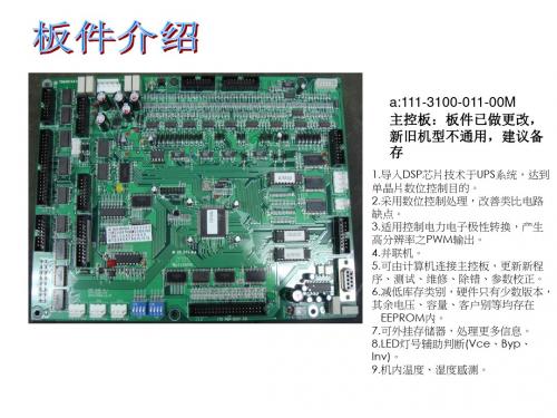
q:110-3125-000-00M NFB板:适用于PGP全 系列并机。
(1)维修旁路开关、输出开关、旁路开关信号侦测利用继电器隔离保护, 防止空开突波发生,造成机器内部电路损害。
(2)将维修旁路开关、输出开关、旁路开关信号侦测通知另一台UPS,避免 两台UPS空开操作不当,造成机器损坏。
1. 多功能交直流两用电源板,提供+5/+15/-15/+12/+24多组输 出电压。
2. 输出具短路保护功能。 3. 宽广的输入电压范围(AC~+/-30%)。 4.风扇检知、风扇四段控制(随负载0%、20%、50%、70%启动
),减少轻载 风扇噪音、且延长风扇使用寿命。 5.电池反接侦测、电池电压侦测。 6.电池接触开关控制,保护电池过放电,寿命减短。
新旧机型通用)
项,使得使用 上更加自由,且多提供一个干接点RELAY供使用者扩充
使用。
18. 使用者自选RELAY1项目功能
-由软件中设定,提供八个干接点选项,可让使用者
通过软件选取个人所需的干接点选项,经由软件设
定,可
让使用上非常的弹性、自由、个人化。且有此功能可
让使用者在使用上不再呆板,免除因硬件已规划的
2. 主要工作电源板失能,系统强制转为旁路运行。 3. 备用工作电源板主要功能:当主要工作电源失能,系统
还有备用电源可以让系 统在旁路运行。
j:112-3311-010-00M 静态开关驱动板:
1.藉由静态开关控制板控制静态开关动作时 机, 使系统达到零时差转换
的特性。 2.DSP软件控制SCR动作时间,减少意外触
功能,
UMD-PP99-037 hep-ph9810442 Gaugino Mass without Singlets
Gaugino Mass without Singlets
hep-ph/9810442 v2 22 Oct 1998
CERN-TH/98-337 LBNL-42419 UCB-PTH-98/50 UMD-PP99-037 hep-ph/9810442
Gian F. Giudicey, Markus A. Lutyz, Hitoshi Murayama , and Riccardo Rattazziy yTheory Division, CERN Geneva, Switzerland z Department of Physics, University of Maryland College Park, Maryland 20742, USA Department of Physics, University of California Berkeley, California 94720, USA
This work was supported in part by the U.S. Department of Energy under Contracts DE-AC0376SF00098, in part by the National Science Foundation under grants PHY-95-14797 and PHY-9802551, and by the Alfred P. Sloan Foundation.
1 Introduction
Supersymmetry (SUSY) is arguably the most attractive mechanism to stabilize the hierarchy between the fundamental scale (e.g. the Planck scale M 1018 GeV) and the electroweak scale (MW 100 GeV). However, superpartners of the standardmodel particles have not been observed up to energies of order MW , so SUSY must be broken at or above the weak scale. The phenomenology of SUSY depends crucially on the mechanism of SUSY breaking and the way that SUSY breaking is communicated to the observable sector. Communication of SUSY-breaking e ects by supergravity (SUGRA) interactions is in some ways the most attractive scenario. In models of this type, SUSY is broken in a hidden sector and gravitational-strength interactions communicate SUSY breaking to the observable sector. The main advantage of this scenario lies in its theoretical appeal: the key ingredients are either present of necessity (e.g. SUGRA) or very wellmotivated (e.g. hidden sectors are generically present in string theories). The main disadvantage of this scenario is that at present there is no convincing explanation for the degeneracy of squark masses required to avoid large avor-changing neutral current e ects. In the context of string theory and SUGRA models with singlets, there are also cosmological problems related to the existence of uncharged elds with almost at potentials and interactions suppressed by powers of the Planck scale. In order to explain the origin of the SUSY breaking scale (and hence the weak scale) the most attractive scenario is that SUSY is broken dynamically 1, 2, 3]. In recent years, it has been found that this occurs in many asymptotically-free supersymmetric gauge theories. In these models, dimensional transmutation generates the hierarchy between the SUSY breaking scale SUSY and the Planck scale, and the SUSY-breaking masses are of order 2 =M . The most important challenge of SUSY constructing phenomenologically viable models of dynamical SUSY breaking in the hidden sector is generating su ciently large gaugino masses 3, 4]. In models without gauge singlets in the hidden sector, the gaugino mass is conventionally believed to be extremely suppressed, at most of order 3 =M 2 ' 1 keV. There have been a variSUSY ety of solutions discussed in the literature 5, 6, 7], all of which involve gauge singlets with SUSY-breaking VEV's, and require more or less complicated model-building. It is not at all clear whether any of these solutions can work in the context of string theory, where one singlet eld, the dilaton, couples to all gauge kinetic terms. Obtaining realistic gaugino masses in string theory therefore appears to require a large F component for the dilaton (in addition to the usual dilaton stabilization problem),
数控加工-数控技术培训学习教程 142页 精品
数控技术培训学习教程随着现代工业设备自动化,越来越多的工厂设备将采用PLC、变频器、人机介面等自动化器件来控制,因此设备自动化程度越来越高。
对设备的维护人员的技术要求越来越严格。
作为一名合格的技术员,需要掌握的技能也越来越多,越来越全面性,以此来满足自动化的发展及要求,因此设备相关的资料及软件,对我们技术员来说是必需具备的,为了满足大家的要求。
经过多年的积累,整理出四种最常用的三菱、OMRON 、AB、及西门子公司的相关资料及软件,特价向大家提供,详细软件资料清单见下面。
A盘:包含:西门子新版LOGOV4.0控制器编程软件,LOGO新版使用手册大全。
新版S7-200PLC中文版编程软件,s7_200_sim模拟软件汉化版,S7-200的中文系统手册大全。
S7-200上位机软件PC_Access_V10。
OP、TP系列中文版编程软件及编程手册大全,WINCC中文版编程手册,Protool中文手册,西门子STEP5教程中文版(NEW),PG702编程器操作手册,所有西门子公司自动化设备相关的中文资料,S7-200与S7-300的应用论文集,S7-200的应用实例中文注释,S7-400.S7-300梯形图(LAD) 中文版编程手册等。
(共650M,详细清单见A 盘说明)B盘:包含:三菱FX、A、Q系列GX-Developer V7.08中文版PLC编程软件及中文使用手册。
三菱FX20GM位置控制器编程软件、三菱PLC程序调试离线仿真软件GX-Simulator6中文版、三菱PLCFX最新FXGPWINV330(中文版),三菱FX系列仿真软件LTT-C简体中文版、三菱PLC可编程控制器教材、FX2N、FX2NC、FX1N、FXNS、FX0N、FX0S系列中文编程手册大全,FX随机手册及模块手册大全,FX-10P、20P编程器中文使用说明,三菱FR系列变频器使用手册大全。
(共650M,详细清单见B盘说明)C盘:包含:OMRON-SSS中文版PLC编程软件,OMRON全系列中文版编程软件CX-P V3.2、Cx-simulator离线仿真软件,人机介面NT系列设计软件,SysWin34OMRON最新开发的智能控制器的编程仿真软件,最新CS1-CJ1-CJ1M 系列PLC中文版操作手册、指令参考手册、编程手册大全、高速计数器、操位置控制、通信单元、温度控制等模块中文手册大全,CX-P中文版软件手册,OMRON PLC培训教材(编程器 SSS使用、CPMIA基础及CPMIA系统)。
How to Order
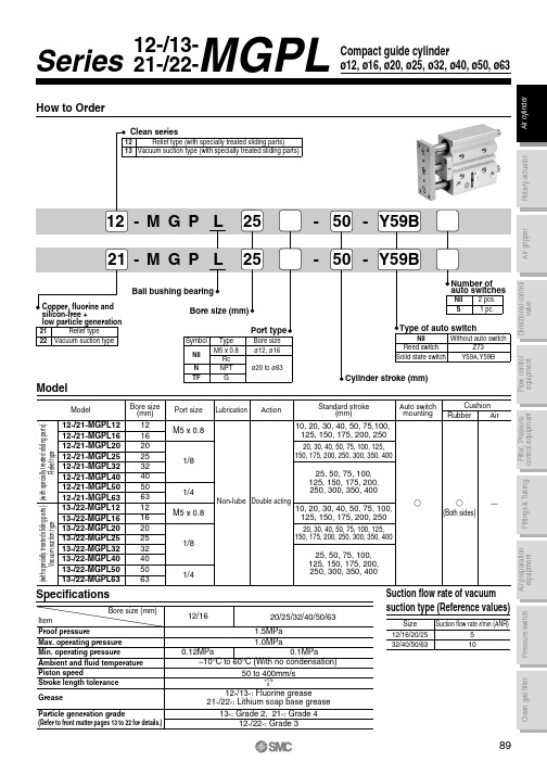
5 to 40mA
Ț
switch 3-wire type
D-Y59A
28 VDC or less
40mA or less
Ț
24 VDC Relay, PLC IC circuit, Relay, PLC
Refer to applicable auto switch list — Page 182.
PLC: Programmable Logic Controller
20 76
93 117 135 66 37 10 10 10
Hale Waihona Puke 275169 10 19 9 36 10.5 8.5 83
25 82.5 98.5 117.5 135 66.5 37.5 12 13 16
32
51 68.5 10 19 9 42 11.5 9 93
Bore size
HA
J
K
L
MM ML NN OA OB OL
25, 50, 75, 100, 125, 150, 175, 200, 250, 300, 350, 400
12/16
20/25/32/40/50/63
1.5MPa
1.0MPa
0.12MPa
0.1MPa
–10°C to 60°C (With no condensation)
50 to 400mm/s
Bore size
WA
30st or Over 30st and Over 100st and Over 200st and less up to 100st up to 200st up to 300st
Over 300st
12 20 40 110 200 –
MB系列PLC软件介绍

MBPro :软件操作
其它信息: 其它信息 在联机状态下通过菜单栏的视图可以 打开SOE事件表和流程报警表,可以查看 SOE事件和流程报警信息。
MBPro :数据类型
类型 BOOL BYTE 名称 布尔型 字节型 位数 1 8 说明 以位为单位存储,只有两个状态:1或0。 使用8位的数据寄存器,8位数据可以是彼此独立,仅表 示当前位的状态:0或1;也可以表示一个无符号整型数, 范围0~255。 使用16位的数据寄存器,16位数据可以是彼此独立,仅 表示当前位的状态:0或1;也可以表示一个无符号整型 数,范围是0~65535。 使用32位的数据寄存器,32位数据可以是彼此独立,仅 表示当前位的状态:0或1;也可以表示一个无符号整型 数,范围是0~4294967295。 使用8位的数据寄存器,表示一个有符号整型 数,范围从-128~+127。 使用16位的数据寄存器,表示一个有符号整型数,范围 从-32768~+32767。 使用32位的数据寄存器,表示一个有符号整型数,范围 从-2147483648~+2147483647。 表示一个浮点数。
-( / )-( P )-( N )-( S )-( R )-
MBPro :梯形图编程
• 梯形图功能模块:定时器 根据用户要求设定时间,在一定条件下开 始计时,计时结束后能够导通电流的功能模块。 有秒定时器TMR(s)、分定时器TMR(m)、时定时 器(h)和毫秒定时器TMR(ms)四种。
使能端
输出
工具栏: 工具栏 • 系统工具栏 • 梯形工具栏 • 流程工具栏
MBPro :软件操作
目录栏: 目录栏 • 硬件配置 • 梯形图 • 流程图
MBN 31010-2_2001.12_DE

Dezember 2001Mercedes-BenzFluidtechnikSchaltplänefür Kraftfahrzeuge und AnhängerfahrzeugeÖlhydraulik und PneumatikBenennungen und graphische SymboleMBN 31 010-2Ersatz fürAusgabe: 1989-05Fortsetzung Seite 2 bis 60Herausgeber:DaimlerChrysler AG 70546 StuttgartNormung (EP/QIN)Fachverantwortung (Name): GurtnerAbteilung: EP/QIN Werk:019Telefon : (0711) 17- 2 08 39HPC:D652Ordnungsnummer 31 500/2Vertraulich! Alle Rechte vorbehalten. Weitergabe oder Vervielfältigung ohne vorherige schriftliche Zustimmung der DaimlerChrysler AG verboten.0 Inhalt1Allgemeines....................................................................................................................................................21.1Zweck.............................................................................................................................................................21.2Anwendungsbereich.....................................................................................................................................21.3Normative Verweisungen.............................................................................................................................21.4Hinweise (22)Symbole..........................................................................................................................................................31Verdichter, Pumpen, Motoren..............................................................................................................32Druckregler.............................................................................................................................................53Frostschutzeinrichtungen....................................................................................................................64Schutzventile.........................................................................................................................................75Energiespeicher.....................................................................................................................................86Wasserabscheider, Trockner...............................................................................................................97Überströmventile.................................................................................................................................118Rückschlag- und Absperrventile .......................................................................................................129Leuchtmelder.......................................................................................................................................1310Druckschalter, elektrisch....................................................................................................................1411Druckmesser........................................................................................................................................1512Signalgeber..........................................................................................................................................1613Betriebsbremsventile für Fremdkraftbremse ...................................................................................1714Feststellbremsventile..........................................................................................................................1915Bremsventile, belüftet mechanisch betätigt.....................................................................................2016Relaisventile.........................................................................................................................................2117Anhängersteuerventile für Einleitungsbremse.................................................................................2218Anhängersteuerventile für Zweileitungsbremse..............................................................................2319Einfachwirkende Zylinder (Hydraulik)...............................................................................................2520Einfachwirkende Zylinder (Pneumatik).............................................................................................2621Doppelt wirkende Zylinder (pneu./hydr.)...........................................................................................2722Kombizylinder (Pneumatik)................................................................................................................2823Bremsgeräte für Fremdkraftbremse..................................................................................................2924Druckverhältnisventile ohne Steueranschluß..................................................................................3025Druckregelventile mit Steueranschluß und variabler Kennlinie.....................................................3126Bremskraftregler automatisch ...........................................................................................................3227Bremsverstärker für Hilfskraftbremse...............................................................................................3328Sperrventile..........................................................................................................................................3429Druckminderventile.............................................................................................................................3530Druckbegrenzungsventile...................................................................................................................3631Regeleinrichtungen; elektr./elektr.-pneum./elektr.-hydraul.............................................................3732Wegeventile mit 3- Schaltstellungen.................................................................................................4033Wegeventile mit 2-Schaltstellungen..................................................................................................4134Behälter (Hydraulik)............................................................................................................................4435Kupplungsköpfe..................................................................................................................................4536Filter......................................................................................................................................................4637Drosselventile......................................................................................................................................4738Druckanschlußstellen.........................................................................................................................4839Entlüftungsstellen...............................................................................................................................4940Drosselrückschlagventile...................................................................................................................5041Wegeventile mit 3 Schaltstellungen.. (51)Seite 2MBN 31 010 - 2 : Dezember 200142Wegeventile mit 4 Schaltstellungen (52)43Luftfederbälge (53)44Feststellbremsventile (54)45Wegeventile mit 2 Schaltstellungen (55)46Gestänge (56)47Wegeventile mit 5 und mehr Schaltstellungen (57)48Verstärker (58)49Proportional Ventile (59)50Medientrenner (60)3Änderungen (60)1Allgemeines1.1 ZweckIn dieser Norm sind alle graphischen Symbole festgelegt, die in Funktionsschemen und in sonstigen Unterlagen bei Anlagen der Ölhydraulik und Pneumatik für Kraftfahrzeuge und Anhängefahrzeuge, z.B. bei Bremsanlagen, verwendet werden.1.2 AnwendungsbereichDiese Norm gilt für alle Schaltpläne der Ölhydraulik und Pneumatik, die in Mercedes-Benz-Fahrzeugen Verwendung finden.Verweisungen1.3 NormativeDIN ISO 1219-11996-03Graphische Symbole und Schaltpläne, Teil 1 graphischeSymbole (Deutsche Übersetzung der ISO 1219-1: 1991).DIN ISO 1219-21996-11Graphische Symbole und Schaltpläne Teil 2 Schaltpläne(Deutsche Übersetzung der ISO 1219-2: 1995).DIN EN 60617-81997-08Graphische Symbole für Schaltpläne Teil 8, Schaltzeichenfür Meß-, Melde- und Signaleinrichtungen.(DeutscheÜbersetzung der IEC 60617-8: 1996)DIN ISO 67861988-10Straßenfahrzeuge – Druckluftbremsanlagen; Kennzeichnungvon Anschlüssen an Geräten. (Deutsche Übersetzung derISO 6786: 1980)DIN 70024-31990-07Begriffe für Einzelteile von Kraftfahrzeugen und derenAnhängefahrzeugen; Bremsausrüstung.DIN 742531994-01Bremsausrüstung für Kraftfahrzeuge und AnhängefahrzeugeGraphische Symbole für Bremsschaltpläne.1.4 HinweiseAnalog zu dieser Norm kennzeichnet jedes Symbol ein Gerät bzw. eine Baugruppe, jedoch nicht seine Bauart. Die Symbole sind in "Nullstellung"1)) dargestellt. Die Symbole gelten sowohl für Hydraulik als auch für Pneumatik, sofern nicht ausdrücklich die Anwendung eingeschränkt wird.Im einzelnen sind diese Symbole festgelegt durch-Übernahme aus DIN ISO 1219 und DIN EN 60617-Kombination von einem oder mehreren Grundsymbolen mit Funktionssymbolen nach DIN ISO 1219 und DIN EN 60617 (wobei bei den einzelnen Geräten die Darstellung auf die Hauptfunktion begrenztwurde; die Art der Betätigung ist im Regelfall nicht Bestandteil des Symbols.)-Festlegung von neuen Symbolen (in Ausnahmefällen).-Darstellung einer einheitlichen Entlüftung nach DIN ISO 1219, Abschnitt 6.2.2.1.-Übernahme der Benennungen der Geräte, soweit zutreffend, aus DIN 70024-3-die den einzelnen Symbolen zugeordnete Nummer (1. Spalte). Sie wird für die Kennzeichnung der Geräte, z.B. im Funktionsschema, verwendet. Fehlende Nummern bzw. leere Gruppen werden vonSymbolen belegt, welche zur Zeit nicht mehr verwendet werden.1) Als Nullstellung wird bei Ventilen mit vorhandener Rückstellung, z.B. Feder, die Schaltstellung bezeichnet, die von den beweglichen Teilen des Ventils eingenommen wird, wenn das Ventil nicht angeschlossen ist. Die Definition der Nullstellung entspricht der Angabe "in unbetätigtem Zustand“ nach DIN 1219.Seite 3MBN 31 010 -2 : Dezember 2001 2SymboleSeite 4MBN 31 010 - 2 : Dezember 2001Seite 5MBN 31 010 -2 : Dezember 2001 Nr.Benennung Anwendung oder Ersatzder Ausrüstung oderErklärung des SymbolsSymbol/Symbole2Druckregler Nach DIN ISO 1219:Druckventilwerden zur Zeit nicht verwendetSeite 6MBN 31 010 - 2 : Dezember 2001Nr.Benennung Anwendung oder Ersatzder Ausrüstung oderErklärung des SymbolsSymbol/Symbole3Frostschutz-einrichtungenNach DIN ISO 1219werden zur Zeit nicht verwendetSeite 7 MBN 31 010 -2 : Dezember 2001Seite 8MBN 31 010 - 2 : Dezember 2001Seite 9 MBN 31 010 -2 : Dezember 2001Seite 10MBN 31 010 - 2 : Dezember 2001Erklärung des Symbols15Bremsventile, belüftetmechanisch betätigtnach DIN 1219(Druckventile)werden zur Zeit nicht verwendetErklärung des Symbols21Doppelt wirkendeZylinder (pneu./hydr.)nach DIN ISO 1219werden zur Zeit nicht verwendetErklärung des Symbols23Bremsgeräte fürFremdkraftbremsenach DIN 70024-3werden zur Zeit nicht verwendetErklärung des Symbols29Druckminderventile werden zur Zeit nicht verwendetErklärung des Symbols37Drosselventile Frei ab Nr. 37.04werden zur Zeit nicht verwendet。
伪罗特水溶性抗渗剂技术数据表说明书

The data on this sheet represent typical values. Since application variables are a major factor in product performance, this information should serve only as a general guide. Valspar assumes no obligation or liability for use of this information. UNLESS VALSPAR AGREES OTHERWISE IN WRITING, VALSPAR MAKES NO WARRANTIES, EXPRESS OR IMPLIED, AND DISCLAIMS ALL IMPLIED WARRANTIES INCLUDINGWARRANTIES OF MERCHANTABILITY OR FITNESS FOR A PARTICULAR USE OR FREEDOM FROM PATENT INFRINGEMENT. VALSPAR WILL NOT BE LIABLE FOR ANY SPECIAL, INCIDENTAL OR CONSEQUENTIAL DAMAGES. Your only remedy for any defect in this product is the replacement of the defective product, or a refund of its purchase price, at our option.Version 2: Feb 2011 (supersedes all previous revisions) (Continued on reverse)Waterborne RetarderTECHNICAL DATA SHEETPRODUCT NUMBERYXT0700COMPANION PRODUCTSZenith™ Coatings, stains, and glaze basesDESCRIPTION/USESZenith™ Waterborne Retarder is designed to increase the open time of Zenith™ coatings, stain, and glaze bases where needed. This may be necessary in conditions of high temperature, excessive airmovement, or when applying coatings to very large pieces where longer open time is needed. This product is not designed for thinning purposes and will not affect viscosity at recommended amounts. Zenith™Waterborne Retarder is designed for professional use only. For Wood Substrates Only.PRODUCT ADVANTAGES• HAP’s Free• Formaldehyde Free • Very low odor •Water cleanupAPPLICATION FEATURES• Easy mixing.•Extends the open time of Zenith™ products.PRECAUTIONSThese products are recommended for professional application and are designed for interior use only. Always pre-test the system on your substrate and under your line conditions to verify suitability to the application and to avoid potential need for costly refinishing. Valspar Wood Finishes products aredesigned to protect and enhance the natural beauty of wood, but cannot eliminate natural discoloration or deterioration of wood as it ages. Additional notes:Do not mix with other finishing systems or deviate from these finishing recommendations. Valspar will not be held liable for finish failures resulting from the mixing of products or deviations from finishing recommendations.PHYSICAL PROPERTIES (objective specifications)Viscosity: N/A Weight Solids: 0 Volume Solids: 0%Weight/Gallon: 8.66 lbs/gal¹ Theoretical Coverage: N/A Flash Point: 999ºF Closed CupAir Quality Information: VOC: 8.66 lbs/gal of Product AIM VOC : 1037.7g/l VOC Ratio: N/A VHAP: 0.0 lb VHAP/lb solid-HAP’s Free Photochemically Reactive: NoDry Times (78°F, 50%RH): Air Dry N/AForce DryN/AShelf life: 2 years from the manufacturing datePot Life: N/AApplication Equipment:Use only equipment with plastic, stainless steel, or Teflon coated valves and parts.Recommended tip sizes : N/ANote: All information provided is typical (as formulated) and will not represent exact values for every product. For specific Air Quality Data for each product, VOC reports are available upon request.FINISHING RECOMMENDATIONSGeneral: Surface must be clean and dust free with moisture content of 6-8% prior to finishing. Remove all dirt, dust, wax and wood marks. Proper sanding and preparation of the wood is critical to achieving consistent results. New Wood: Finish sand surface (150-180 grit) and remove all sanding dust.Painted or Varnished Wood: Remove all paint or varnish then follow new wood instructions.Before using, mix product by hand, or if using mechanical agitation such as an air mixer or drill, mix at slow to moderate speed until there is no material on the bottom of the container.The Zenith™ product line is packaged ready to use. However, certain conditions of high temperature, excessive air movement, or size of the piece to be sprayed may require a longer open time than normal. Such conditions may warrant the use of Zenith™ Waterborne Retarder. Amounts of addition are specific to each product. Please refer to the following table to maintain regulatory compliance:Zenith™ clear sealer and topcoatsLKF700X series, PKF720X series, PKF750X series, PKS7200: Add 1-5 oz (1-4%) max per gal. Max VOC after recommended addition is 275 g/l or 2.3 lbs per gallon.Zenith™ basecoats and white topcoatsLKW7100, LKN7200, LKW710X series, PKW730X series: Add 1-4 oz (1-3%) max per gal. Max VOC after recommended addition is 275 g/l or 2.3 lbs per gallon.Zenith™ stains and glazesLWS075X series: Add 1-2.5 oz (1-2%) max per gal. Max VOC after recommended addition is 250 g/l or 2.08 lbs per gallon.LWS4750: Add 1-2oz (1-1.5%) max per gal. Max VOC after recommended addition is 250 g/l or 2.08 lbs per gallon. LWS4725: Add 1-2oz (1-1.5%) max per gal. Max VOC after recommended addition is 250 g/l or 2.08 lbs per gallon. LWS1000: Add 4-7oz (3-5%) max per gal. Max VOC after recommended addition is 120 g/per liter of Material.For Zenith products/series not listed-No retarder is recommended.Note: Adding Zenith™ Waterborne Retarder will increase the dry time needed before re-coating. The amount ofextra time needed will depend on ambient conditions and air movement. Make sure products are thoroughly dry before re-coating.Caution: Exceeding recommended amounts may cause severely extended dry times and cause a soft film in the early curing stages.Clean equipment with warm water. If coating has dried, Acetone may be required to remove dried film. Keep container closed when not in use to avoid skinning. Do not transfer contents to other containers for storage or disposal. In case of spillage, absorb with inert material such as sand or kitty litter. Dispose of empty cans or unused portion in accordance with local state and federal regulations.Store in a cool, dry place. DO NOT FREEZE! Product should be stored in temperatures between 50°-110°F. Close all containers after use. Do not store near heat or sparks. Spills should be cleaned up with non-sparking tools. See the product MSDS for complete safety information.Always pre-test the system on your substrate and under your line conditions to verify suitability to the application and avoid potential need for costly refinishing. All dry times listed are as tested under ideal indoor environmental conditions of 78°F (26°C) with relative humidity not exceeding 50%. These products are recommended for use under temperature conditions of 60-100°F (16-38°C) and when relative humidity is below 50% during application and drying time. Low temperatures, poor air circulation or high humidity will extend dry times. Valspar strongly recommends against use of these products if temperatures of air, material, or surface to be coated are below 60°F (16°C) or below the dew point. Abnormal conditions of temperature or humidity may adversely affect product performance. Please contact your authorized Valspar Wood Finishes distributor for additional product use recommendations and finishing guidance.MSDS AND CPDS SHEETS AVAILABLE UPON REQUEST。
关于SG-TCP232-110单通道串口服务器
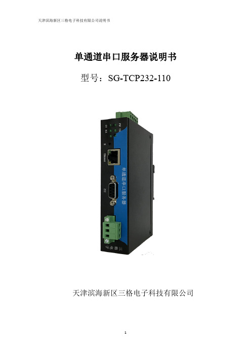
单通道串口服务器说明书型号:SG-TCP232-110天津滨海新区三格电子科技有限公司一、产品介绍1.1功能简介SG-TCP232-110是一款用来进行串口数据和网口数据转换的设备。
解决普通串口设备在Internet上的联网问题。
设备的串口部分提供一个232接口和一个485接口,两个接口内部连接,同时只能使用一个口工作。
设备的网口部分提供一个带数据和连接指示灯的RJ45接口,支持10/100Mbps 自适应以太网接口,支持AUTO-MDIX 网线交叉直连自动切换。
串口的232接口和485接口支持波特率从1200到115200bps,可选奇偶校验,可选停止位长度。
设备支持TCP Sever、TCP Client、UDP Sever、UDP Client、Modbus TCP Sever、Modbus TCP Client六种工作模式。
支持DHCP功能,支持DNS功能,支持自定义MAC,自定义心跳包时间和内容,可以跨越网关,可以访问外网。
设备支持通过软件和硬件恢复出厂设置,支持通过软件和网页进行配置。
1.2工作模式设备支持TCP Sever、TCP Client、UDP Sever、UDP Client、Modbus TCP Sever、Modbus TCP Client六种工作模式TCP Sever模式:在TCP Server 模式下设备首先与网关尝试通讯,然后监听设置的本机端口,有Client连接请求时响应并创建连接,最多可同时存在4个TCP Client连接。
设备收到Client的数据后转发到串口,串口收到数据后将同时发送给所有与设备建立连接的设备。
TCP Client模式:设备上电后根据目标IP及目标端口号主动去连接到TCP 服务器端,然后建立一个长连接,之后的数据进行透明传输。
此模式下,TCP Server 的IP 需要对设备可见,即通过设备所在的IP可以直接PING通服务器IP,服务器端可以是互联网的固定IP,也可以是和设备同一个局域网的内网IP。
西农 机电一体化实习报告

《机电一体化综合训练》实习报告姓名:学号:专业班级:实验指导教师:李星恕、李卫、郭红利、侯俊才西北农林科技大学机械与电子工程学院2015年7月一、蔬菜移栽机1、蔬菜移栽机研究意义和现状我国是世界蔬菜生产大国,随着农村产业结构的调整和蔬菜产业的发展,国家对高效设施农业的发展越来越重视,对蔬菜生产机械的需求日益迫切。
而蔬菜移栽机械化作业对于提高秧苗移栽质量、提高劳动生产率以及减轻农民劳动强度具有重要意义。
近年来,设施蔬菜生产已经遍布全国各地,蔬菜育苗工作取得重大突破,灌溉和植保技术突飞猛进,但是,蔬菜移栽机械化进展缓慢。
而手工移栽是仅次于收获作业的一项劳动强度非常大的劳动。
实现蔬菜移栽机械化已成为农业生产的迫切需要。
我国旱地栽植机械的研究始于20世纪50年代末60年代初。
20世纪70年代开始研制裸根苗移栽机械,80年代研制成半机械化蔬菜栽植机。
但是,这些机具由于与育苗方式不配套或不能满足蔬菜栽植的农艺要求等原因而没有得到推广应用。
近几年来,随着育苗技术的发展以及劳动力成本的上升,推动了移栽机械的研制开发工作。
目前,国内已经研制开发出钳夹式、链夹式、挠性圆盘式、吊杯式、导苗管式等各型移栽机。
接下来以久保田蔬菜移栽机为例进行介绍。
2、久保田蔬菜移栽机的结构日本株式会社久保田(KUBOTA)是个百年企业,迄今已有120年的历史。
现在,通过水道用铁管、农业机械和环境设施等各种产品,在完善现代供排水系统、提高粮食产量和减轻劳动强度以及人类和环境的和谐共处等方面,为人们的生活和社会的发展做出了广泛的贡献。
久保田将本着“通过提供人类生活的基础产品、技术和服务,为社会的发展和保护地球环境做贡献”的经营理念,进行全球性的事业拓展,以解决“粮食”“水”“环境”这一世界性的课题。
本次实习研究的是久保田蔬菜移栽机,该机器主要由投苗杯、接苗杯、开沟器和镇压轮等机构组成。
该机器设备的机械结构如下图:3、蔬菜移栽机的工作原理该机具主要适合移栽钵体苗,为自走式。
Experimental demonstration of 110-Gb-s unsynchronized ... -- OE
13. F. Horlin, J. Fickers, P. Emplit, A. Bourdoux, and J. Louveaux, “Dual-polarization OFDM-OQAM for communications over optical fibers with coherent detection,” Opt. Express 21(5), 6409–6421 (2013). 14. P. Amini, R. Kempter, and B. Farhang-Boroujeny, “A comparison of alternative filterbank multicarrier methods in cognitive radio systems” in Proceedings of SDRTC' 2006. 15. D. Chen, D. Qu, and T. Jiang, “Novel prototype filter design for FBMC based cognitive radio systems through direct optimization of filter coefficients” in Proceedings of WCSP'2010. 16. K. Arya and C. Vijaykumar, “Elimination of Cyclic Prefix of OFDM systems using filter bank based multicarrier systems” in TENCON IEEE Region 10 Conference. IEEE, 2008. 17. L. Vangelista and N. Laurenti, “Efficient implementations and alternative architectures for OFDM-OQAM systems,” IEEE Trans. Commun. 49(4), 664–675 (2001).
PIP3221-DC资料

VS3102用户手册

VS3102用户手册北京华青紫博科技有限公司北京华青紫博科技有限公司目录目录 (1)第一章使用之前 (4)第二章包装目录 (4)第三章物理描述 (5)3.1 前面板 (5)3.1.1 视频输入BNC口 (6)3.1.2 音频输入RCA口 (6)3.2 后面板 (6)3.2.1 以太网10/100接口 (6)3.2.2 COM接口 (6)3.2.3 通用I/O模块 (7)3.2.4 状态指示灯 (7)3.2.5 恢复按钮 (8)3.2.6 电源变压器 (8)第四章如何安装 (8)第五章以太网环境 (9)5.1 硬件安装 (9)5.1.1 如何联接 (9)5.1.2 开机 (9)5.2 软件配置 (10)5.2.1使用安装软件 (10)5.2.2 用已有的程序来进行手动设定 (13)5.3 第一次访问视频服务器 (13)第六章调制解调器环境 (14)6.1 硬件安装 (14)6.1.1 电缆连接 (14)6.1.2 接通电源 (15)6.2 软件配置 (15)6.2.1 安装一个新的调制解调器 (15)6.2.2 设置新的连接 (17)6.3 第一次连接视频服务器 (20)第七章如何使用 (21)7.1 用户名和密码 (21)7.2 初级用户的使用 (22)7.2.1 带摄像机显示的主屏幕 (22)7.2.2 云台控制 (23)7.2.3 用户设定 (23)7.3 系统配置 (25)7.3.1 系统参数 (26)7.3.2 用户组管理 (27) 1北京华青紫博科技有限公司7.3.4 视频编码参数 (29)7.3.5 视频动态检测 (30)7.3.6 云台控制配置 (31)7.3.7 调制解调器和拨号设定 (34)7.3.8 应用 (35)7.3.9 主页布局设定 (36)7.3.10 用FTP进行快速配置 (36)7.4 高级功能 (42)7.4.1 网页 (42)7.4.1.1 显示系统日志 (42)7.4.1.2 显示系统参数 (42)7.4.1.3 恢复出厂设定 (43)7.4.1.4 个人自定义明文命令的路径 (43)7.4.2 FTP (43)7.4.2.1 周期性地上载快照文件到外部FTP服务器上 (43)7.4.2.2 自定义主页中的图片 (43)7.4.2.3 显示系统日志 (44)7.4.2.4 上载配置文件 (44)7.4.2.5 软件版本升级 (44)7.4.3 Telnet (45)7.4.3.1 系统内核调试 (45)7.4.3.2 监视数字输入的状态改变 (45)7.4.3.3 停止信息打印 (45)7.4.3.4 查询数字输入状态 (45)7.4.3.5 设置数字输出 (46)7.4.3.6 删除闪存中的快照 (46)7.4.3.7 删除公司标和图像按钮 (46)7.4.3.8 下次启动时跳过安装 (46)7.4.3.9 重置网络重新安装 (46)7.4.3.10 恢复出厂设定 (46)7.4.3.11 重启系统 (46)7.5 视频服务器的URL命令 (46)7.5.1 捕捉快照 (47)7.5.2 移动云台 (47)7.5.3 预置/招回摄像机位置 (47)7.5.4 查询数字输入的状态 (47)7.5.5 数字输出 (47)7.5.6 明文命令的串口驱动 (47)7.5.7 恢复出厂设定 (48)7.5.8 重启系统 (48)7.5.9 页URL命令 (48)7.5.11 命令URL的常用格式 (49)7.5.12 系统配置URL (49) 2北京华青紫博科技有限公司7.5.13 安全配置URL (49)7.5.14 网络配置URL (50)7.5.15 视频配置URL (50)7.5.16 图像质量配置URL (52)7.5.17 摄像机配置的URL (52)7.5.18 摄像机位置预置URL (52)7.5.19 摄像机自定义命令配置URL (52)7.5.20 自定义摄像机配置URL (53)7.5.21 调制解调器配置URL (53)7.5.22 应用配置URL (54)7.5.23 主页布局配置URL (54)附录 (55)A. 自检顺序 (55)B. 常见问题 (55)C. 技术参数 (58) 3北京华青紫博科技有限公司第一章使用之前尽管视频服务器不仅是一个高效的监控设备,而且也是一个网络视频服务器,然而在安装本监控设备之前要确定它是合法的.打开盒子后,请务必检察一下盒子中的物品.了解一下盒中物品的物理特性,能防止对它们的非正常使用伤害,并减少安装时出现的大部分问题.视频服务器是一个网络设备,如果用户有基本的网络知识的话,对用户来说它应该很容易使用.如果配置出现错误,导致出现系统问题,而且恢复起来很困难,参见"附加按钮"节来恢复系统默认设置并重新运行安装程序.视频服务器为不同的环境设计,并能构造不同的安防或演示目的的应用.对标准的应用请阅读"系统配置"以理解所有的功能.想更好的使用视频服务器,请详细阅读"高级功能".至于专业的开发商,"视频服务器的网页命令"这一章将会非常有用.带警告标志的章节必须完全理解并小心操作.忽视这些警告将导致严重后果.第二章包装目录视频服务器VS3102电源变压器I/O终端模块扳手 4北京华青紫博科技有限公司摄像机控制电缆串口联接线应用程序光盘快速安装向导质保卡第三章物理描述3.1 前面板 5北京华青紫博科技有限公司3.1.1 视频输入BNC口视频输入口阻值为75hms.为确保视频调制模式检测正确,摄像机必须在视频服务器打开之前打开.3.1.2 音频输入RCA口音频输入用RCA口引入单声道Line in信号.3.2 后面板3.2.1 以太网10/100接口用UTP5电缆连接到以太网,极限长度是100米.当网络连接线没有问题时,视频服务器会忽视modem连接.3.2.2 COM接口RS232串口能连接调制解调器或直接用串口连接线.如果视频服务器选择的是以太网模式的话,管理员可以用本串口来用来控制VIDEO上所接的云台. 6北京华青紫博科技有限公司3.2.3 通用I/O模块序号名称输入/输出范围1 DI+ INPUT 12VDC 最大50mA2 DI- INPUT3 SW_COMMON OUTPUT 初始时与NC短接4 SW_NOPEN OUTPUT 24VDC时1A或125V A C时0.5A5 RS485 B D- 倒转6 RS485 A D+ 非倒转视频服务器提供了非常灵活的I/O模块来连接用户的安防设备,如传感器,报警器,灯光或门锁.通用I/O模块共有6个管脚.这些管脚可按它们的功能分成两种类别,分别是:RS485和数字输入输出.如果联接到串口上的设备是RS485接口的话,请接脚5和6.在配置页将接口转换成RS485,云台控制命令可直接通过脚5和6发送.如果距离太远导致无法正常工作,可外接电源拉高RS485信号.视频服务器提供1个数字输入和1个继电器出.脚1到脚2可用来联接外部传感器,它们的电压状态可按照配置页上的编程脚本来监控.继电器开头可以用来找开和关闭外接设备.3.2.4 状态指示灯当视频服务器启动时,系统将进行自检,检查系统的各个硬件.当接通电源时,电源指示灯下面的状态指示灯都会一个接一个地闪动,直到自检过程结束.如果有模块不正常,状态指示灯会按照附录A中的列表指示错误.如果自检通过,状态指示灯会关闭一段时间,然后按如下表显示.网络接口取决于所连接的UTP网线,调制解调器或串口连接线.如果交换机和视频服务器的连接良好的话,视频服务器会选择以太网接口.如果找不到以太网接口,而连接的调制解调器工作正常的话,网络接口会选择成调制解调器的PPP连接.如果上面的两种接口都找不到的话,视频服务器会试图用串口的PPP连接.网络接口条件LED1(心跳) LED2(状态)安装前灭灭安装后闪灭以太网摄像机控制过程中闪闪 7北京华青紫博科技有限公司modem ppp 自检后闪亮连接前亮亮连接后闪亮串口直接连接3.2.5 恢复按钮盒子上隐藏着一个用来恢复出厂设定值的按钮.当系统安装和工作不正常时,用包装中所带的小棍并按如下步骤操作来将系统恢复到原来的设置.用小棍伸进小孔按住恢复按钮.拔下和插上电源插头使系统重启.按住恢复按钮时,系统将会进行两次自检,而平时是一次自检,这可以从闪动的状态指示灯看出来.当摄像服务器的状态指示灯第二次闪动时,松开小棍.系统此时就会恢复出厂设定值.3.2.6 电源变压器将视频服务器联接到电源变压器的插孔上.当安装视频服务器时,开电是最后一个动作.第四章如何安装为方便的安装到各种环境下,视频服务器自动检测联接的接口,并按照最好的条件配置自已.也就是说,用户无需关心所联接摄像头是N制的还是PA L制的;所联接的网络是以太网还是MODEM,以太网的速度是10M或100M.如果联接的可调摄像头在支持列表中,用户无需复杂的配置就能即插即用.视频服务器支持以太网和调制解调器.以太网可以提供高带宽并得到最好的性能,同时拨号网络在通常的INTERNET应用是最常见的.参考相关的章节来询求你的网络环境的安装.如果两种环境都可用的话,推荐使用以太网,而且它也会被优先选用.从一种网络环境转移到另一种网络环境会清除前一种网络环境的设置.在下面的章节中,"用户"指可以使用视频服务器的人,"管理员"指除了能使用视频服务器外,而且还有root密码,能对它进行配置.管理员应该仔细阅读本手册,特别在安装过程中. 8北京华青紫博科技有限公司第五章以太网环境5.1 硬件安装在安装网络服务器之前,记下包装上的序列号以便将来使用.5.1.1 如何联接联接前关掉所有的周边设备.按照如下的步骤联接相关的设备.注意在联接好所有的设备之前不要插电源插头.5.1.2 开机请确保所有的电缆联执接正确和牢固,打开摄像头,传感器,报警设备然后将插头接到电源插座上.在自检完成并正常后,摄像服务器准备好进行软件配置. 这时,网络速度和视频调制模示是自动检测的.如果检测的视频调制模式不正确, 管理员可以在配置页改变设定.参见配置章.先将电源变压器的插头连接到视频服务器上,再插电源插头,这会减少电涌事故. 9北京华青紫博科技有限公司5.2 软件配置5.2.1使用安装软件为了远程配置摄像服务器,管理员应该记住新的视频服务器的序列号,并用它们做为身份认证和初始密码.当安装好视频服务器后,在PC上运行安装程序来定位刚安装的视频服务器.视频服务器也支持非WINDOWS下的手动安装模式.手动步骤以后讨论.当自检完成后,视频服务器会自动检测网络环境并自动配置.如果在网上有DHCP服务器的话,安装程序会得到给定的信息并显示序列号和每个视频服务器的IP地址.如果没有DHCP服务器的话,前一个IP地址会被显示.在这种情况下,新设备会显示0.0.0.0.当安装了多个设备后,程序将会显示多个设备.管理员可以点击"ASSIGNED"栏为"NO"的设备来进行配置.在当前IP地址栏显示的IP地址只是作为管理员的参考.如果管理员想用另外一个IP地址的话,直接修改下面的编辑框输入新的IP地址.如果想固定要机的IP地址的话,选择"无论何时系统启动时都使用此IP地址"来跳过进一步的设置,否则设备启动时都需要进行配置. 10北京华青紫博科技有限公司当IP和选项都输入完成后,点击"Set IP Address".弹出信息对话框通知管理员IP 地址是否合法.如果IP地址没有被其它网络设备使用的话,安装程序将继续.否则将弹出另外一个信息窗口显示IP地址冲突.在这种情况下,管理员应该咨询网络管理员来得到一个合法的IP地址.在显示成功设置IP后,管理员应该记住所设置的IP以便用户使用. 11北京华青紫博科技有限公司当点击了确定后,"设置"栏将会显示为"Y es".管理员可以直接点击"Link to selected camera"来用默认的浏览器连接指定的摄像机.当选择了"无论何时系统启动时都使用此IP地址"后,弹出对话框询问"服务器FTP端口"和"Root密码",这是因为它们被改变成了其它的数值.如果设定值丢失,恢复出厂设定并重新运行安装程序来安装.一旦安装结束后,管理员应该按照"第一次安装视频服务器"章来进行必要的检查和配置.有经验的管理员可以用定制的config.ini文件通过FTP来进行快速的设置.详细的步骤可以在"通过FTP快速配置"章找到. 12北京华青紫博科技有限公司如果想要用一个容易记住的名字来连接视频服务器的话,管理员可以在网络的名称服务器上配置一下.下面是一个例子:管理员已经设置视频服务器了一个固定的IP,而且想通过名字而不是难记的IP来连接它,管理员应该在DHCP服务器上为此视频服务器预留IP,并在域名服务器上将名称指定为对应的IP.当安装视频服务器时,设置它的IP为预留的IP.这样安装完成后就能用给定的名字来连接视频服务器了.5.2.2 用已有的程序来进行手动设定对应用环境是MA C,Linux,Unix或其它一些操作系统的环境下,我们还没有提供安装程序,一些常用的网络应用程序例如ARP和PING可以用来安装视频服务器.请先确认ARP和PING命令存在.首先,键入命令:arp -s "给定的IP地址" "网卡地址"这就在系统的名称表中增加了一项.网卡地址是指视频服务器的序列号,用如下的格式输入:uu-vv-ww-xx-yy-zz或uu:vv:ww:xx:yy:zz,选择哪种输入方式取决于操作系统.当名称项加入后,输入命令:ping "给定的IP地址"如果命令有回应的话,则IP地址设置成功,并可以用它来访问视频服务器.最开始的几个PING的反应会失败,因为此时视频服务器在进行自动配置.由于ARP和PING命令的语法取决于操作系统,所以请参考它们的帮助手册.5.3 第一次访问视频服务器当第一次连接到视频服务器时,管理员应该检查在系统配置页的安全和网络设定.为了防止非法使用,视频服务器提供两种权限,而且在访问前均需要用户名和密码.标准级别是用户模式,由20个用户权限组成.每个用户都能访问视频服务器,除了系统配置.这二十个用户权限也由管理员维护.最高的级别是ROOT模式,仅开放给管理员来做初始化,系统配置,用户管理和软件升级.管理员的用户由系统内定为"root".当连接上视频服务器后,用户将被提示来输入用户名和密码.与视频服务器的序列号相同的root密码将用来作系统的安装动作.管理员应该在做完初始化安装动作后立即修改密码以确保安全.新的root密码应该记好,因为没有办法获取或修复它.当改变完密码后,浏览器会弹出密码窗口要求用户再次输入新的密码.另一个重要的部分是网络设定.上面的软件配置使通过本地网络来访问视频服务器变得很容易.然而,管理员应该检查在系统配置页的网络配置,看看它是否符合已有的网络环境.安全和容易的方法是把它与已有的PC或工作站上的网络配置进行对比.前面章节中的软件安装只设置主机的IP地址和默认子网掩码为255.255.255.0.管理员应该按照本地网络来修改这个默认的子网掩码.如果需要的话,管理员也应该输入默认网关,主次DNS服务器. 13北京华青紫博科技有限公司默认状态下,视频服务器会在每次重启后要求管理员重新进行安装.如果网络设定确实不用每次重启后都改变的话,将此项安装选项失效.这样做会在下次视频服务器启动时跳过安装过程,直接使用前次的配置.如果使能此项安装选项,视频服务器会在下次启动时执行安装步骤.配置的详细描述在"如何使用"章.为了方便起见,相关图片也包含在内.第六章调制解调器环境6.1 硬件安装在安装视频服务器前,管理员应该记住包装上的序列号,因为它是最初的密码.为了使用拨号网络,网卡的接口应该断开,因为网卡是最优先的接口.当加电后,视频服务器会检测是否有外接的调制解调器连接在com口.当检测到有调制解调器后,芯跳指示灯会周期性地闪动.如果没有检测到调制解调器,视频服务器会默认为连接着串口连接线,并进行系统配置工作.此时电源指示灯下的两个指示灯都会点亮直到串口连接上.如果用户配置过远程拨号服务器或有ISP服务的帐号,视频服务器可以配置以在特定的条件下拨入到服务器.否则它会等待用户的呼叫来建立网络连接以提供服务.在下面的叙述中,拨入连接指视频服务器等待用户的拨入来建立点到点的连接.拨出连接指视频服务器拨出到另一个拨号网络服务器或任一ISP,要求点到点的连接.6.1.1 电缆连接关掉所有的周边设备的电源,然后将它们连接到视频服务器上.按照如下的顺序连接周边设备.注意在所有的周边设备连接好前,不要插上电源插头.没有 14北京华青紫博科技有限公司网卡第一次访问视频服务器时,管理员可以用随机携带的直接串口连接线直接连接到COM上.用直接串口连接线连接也是很方便的,它不需要调制解调器也不需要网卡.当输入必要的参数后,视频服务器就能用调制解调器来拨入到internet.6.1.2 接通电源在接通电源前,请确认所有的连线均连接牢固.打开摄像头,传感器和报警设备,最后将摄像服务器的插头插到接线板上.由于当系统重启时要进行所有的硬件检测,视频服务器应该在所有的周边设备打开前打开.先将电源变压器的插头连接到视频服务器上,再插电源插头,这会减少电涌事故.6.2 软件配置初次使用时,用户应该将产品自带的串口直连线连接到视频服务器的COM口和计算机的任一COM上.6.2.1 安装一个新的调制解调器打开控制面板并双击"调制解调器"的图标将"不检测调制解调器,直接从列表中选取"打上勾,点击"下一步". 15北京华青紫博科技有限公司在"标准调制解调器类型"这一栏选择"标准33600bps调制解调器",点击"下一步".选择串口连接线所连接的串口,点击"下一步",则串口连接就连好了.如果计算机中没有安装拨号网络的话,windows会自动提醒用户安装一个.如果没有自动启动安装的话,请双击控制面板中的网络图标来安装一个. 16北京华青紫博科技有限公司6.2.2 设置新的连接安装好33600的调制解调器后,打开windows中的"拨号网络"文件夹来设置一个新的连接.双击"建立新连接".在设备处选择新装的调制解调器,点击"下一步".随便输入电话号码,点击"下一步",这里所输入的电话号码没有用处.点击"完成"后,新建连接就会显示在拨号网络中. 17北京华青紫博科技有限公司右键点击新建的连接,选择属性.在常规页,清除"使用区号与拨号属性",点击"设置".选择最快速度为115200,点击确定. 18北京华青紫博科技有限公司在第二页"服务器类型"中,只选择"启用软件压缩"和"TCP/IP",其它的都不选.然后点击确定.此时就设置好了新建的连接.双击此新建的连接,弹出拨号窗口.用户名用root,密码处输入视频服务器的序列号,然后点击连接.此处的用户名和密码与在web浏览中的一样,也可以由管理员在安装成功后修改.请注意序列号中的字母的大小写.例如输入'A'而不是'a'.提示了一些信息后,连接提示窗口会显示连接成功为115200bps.连接成功后,请接着看下一节"第一次连接视频服务器". 19北京华青紫博科技有限公司如果显示连接错误,特别是在windows2000环境中会有错误,请参考错误信息来修复错误.6.3 第一次连接视频服务器通过用串口连接线,管理员可以打开默认的网页浏览器,在地址栏输入200.1.1.1,然后回车.注意200.1.1.1是视频服务器的地址,而200.1.1.100是给用户PC的地址.用户名和密码与安装时输入的一样.当用户名和密码正确后,管理员会在主页上看到动画图像.当使用的IE时,管理员应该允许安装一个由视频服务器提供的插件.为了安全起见,管理员应该立即在配置页修改密码.改变完密码后,浏览器会再次显示密码提示窗口,提示输入新密码.注意下次拨号时应该用新改的密码.为使视频服务器在拨入和拨出方式下正常工作,参考如下的步骤做基本配置.如果管理员以外的人员想连接视频服务器的话,管理员应该在配置页中安全选项增加这些用户的权限.当视频服务器作为服务器接受连接后,拨号框中显示的用户名和密码和在网页中连接视频服务器的用户名和密码是一样的.所有的授权用户都可以通过PPP拨号来连接视频服务器.而只有管理员才能使用配置页. 正确的调制解调器操作需要更多的信息.请参见配置页中的调制解调器设置这一节.视频服务器将等待拨入.如果管理员在程序中设置了一些条件的话,视频服务器会按管理员的配置自动拨出.参见配置中的应用章节来得到特定的安全应用.当所有的条件都设置好和保存后,关闭视频服务器并将串口联接线换成调制解调器,以用于拨号网络.由于串口直接连接用于配置视频服务器以利于调制解调器连接,管理员在重启机器前将不能再次连接.如果拨号配置激活后,视频服务器会拨号并将系统启动记录发出以测试设置,并在预配置期后挂断电话. 20北京华青紫博科技有限公司第七章如何使用视频服务器是一个完整设计的独立视频服务器.自带网页服务,授权用户可以用常用的网页浏览器如IE和Netscape Navigator来浏览视频服务器捕捉的图像.强力的视频压缩处理每秒30帧图像而且使浏览器实时显示.使用网页界面的另一个有利之处是所有的功能和配置都有它们自己的URL,这样高级用户就能很方便地将它们集成到已有的程序中.初级用户使用视频服务器非常简单,因为所有的主要安装动作都由管理员做过了.大部分管理员会发现安装过程很容易,因为在通常的环境中,大部分的配置都已经自动配置过了.打开你熟悉的网页浏览器,象连接普通网页一样连接到视频服务器上,然后图像就会按要求显示在屏幕上.请确保目标视频服务器的网址是正确的.7.1 用户名和密码打开浏览器和输入视频服务器的网址后,弹出对话框要求输入用户名和密码.如果管理员是初次使用,输入用户名为root,密码是大小写敏感的序列号.序列号可以在视频服务器的下面的标签的上方找到.初级用户在管理员授权完后就能进入了.输入完正确的用户名和密码后,主页面就会显示出来.下图中,前面的窗口是注册窗口,背景显示了注册失败的显示信息.用户可以选择为将来的方便保存密码.如果是第一次从windows中访问视频服务器,IE会提示安装一个由视频服务器提供的插件.这个插件用来注册为证书并用来在IE中显示活动的图像.用户可以点击yes来安装插件.如果浏览器不让用户安装,将安全设置为低安全级或咨询网络管理员. 21北京华青紫博科技有限公司7.2 初级用户的使用7.2.1 带摄像机显示的主屏幕左上角有一个公司标的图像.它可以按照配置页的设定链接到别的网站或资源.给定的题头和日期/时间会显示在图像上面的横幅上.图像会在检测到有视频移动时显示一个或几个红色的框.点击图像左边的"Configurate"来对视频服务器进行配置. 22北京华青紫博科技有限公司7.2.2 云台控制带云台的摄像机由用户提供并安装正确.用户能通过图像右边的控制面板调节摄像机做上下左右移动和缩放.要使用预设的位置,点击Preset Position下拉列表框选择一个然后点击Go.只有管理员才能预设摄像机的位置.初级用户仅能浏览这些预设位置.图像下的五个按钮可以用来控制摄像机来做除了上下左右。
V23832-R111-M101中文资料

Parallel Optical Link Transmitter:PAROLI ® 2 Tx AC, 1.6 Gbit/s Parallel Optical Link Receiver:PAROLI ® 2 Rx AC, 1.6 Gbit/sFile: 3104Fiber OpticsV23832-T2131-M101 V23832-R121-M101Design Benefits •Relieve system bandwidth bottle necks •Simplifies system design•Enables system upgrades in field•Low power consumption at increased board density •Flat package for height critical applicationFeatures •Infineon’s highly reliable 850 nm VCSEL technology •Power supply 3.3V•Transmitter with multistandard electrical interface •Receiver with LVDS electrical interface •12 electrical data channels•Asynchronous, AC-coupled optical link •12 optical data channels•Internal power monitoring for constant power budget•Transmission data rate of up to 1600Mbit/s per channel, total link data rate up to 19Gbit/s •PIN diode array technology•Optimized for 62.5 µm multimode graded index fiber •MT based optical port (MPO connector)•Plug-in module with ultra low profile•IEC Class 1M laser eye safety compliant •GBE mask compliant modules available •EMI-shielding for front panel access •Standard link length compliant•Unused transmitter channels can be switched off •DC or AC coupling of input data •Telcordia compliantApplicationsOptical Port•Designed for the industry standard 12 fiber MT Connector (MPO)•Alignment pins fixed in module port•Integrated mechanical keying•Module is provided with a dust coverFeatures of MT Connector (MPO)(as part of optional PAROLI fiber optic cables)•Uses standardized MT ferrule•MT compatible fiber spacing (250µm) and alignment pin spacing (4600µm)•Push-pull mechanism•Ferrule bearing spring loadedFeatures of the PAROLI 2 Electrical Connector•Pluggable version using BGA socket•100 pin positions (10x10)•4mm stack height in mated conditions•Plug and receptacle are provided with protective cap•Standard BGA process for socket assembly•Contact area plating made out of gold over nickel•Module side: FCI-MEG-Array® -Plug (part no. 84512-202)•PCB side: FCI-MEG-Array® -Receptacle (part no. 84513-201)Applications•Switches, routers, transport equipment•Mass storage devices•Access network•Rack-to-rack/board-to-board interconnect•Optical backplane interconnectPin ConfigurationFigure 1Pin Information TransmitterNumbering Conventions Transmitter (bottom view)J IHGFEDCBA1V EEDI05NDI05PDI06NDI06PDI07NDI07PDI08NDI08PV EE2DI04P VEE V EE V EE V EE V EEV EE V EE V EEDI09N 3DI04N V EE Reserved Reserved t.b.l.o.t.b.l.o.Reserved Reserved V EE DI09P 4DI01P V EE Reserved Reserved t.b.l.o.t.b.l.o.Reserved Reserved V EEDI12N 5DI01N V EE V EE V EE t.b.l.o.t.b.l.o.V EE V EE V EE DI12P 6DI02P V EE V EE V EE t.b.l.o.–LE V EE V EE V EE DI11N 7DI02N V EE V EE V EE LCULEV EEV EE V EE DI11P 8DI03P V EE V EE V EE V IN –RESET V EEV EE V EE DI10N 9DI03NV EE V EE V EE V CC V CC V EE V EE V EE DI10P10V EE V EEV EEV EEV CCV CCV EEV EEV EEV EEThis edge towards MPO connectorPin Description TransmitterSymbol Level/Logic DescriptionVCCPower supply voltage of laser driverV IN CML: V IN = Reference supply (e.g. V CC) LVDS, LVPECL: V IN = V EEVEEGroundLCU LVCMOSOut Laser Controller Up.High = normal operation.Low = laser fault or RESETlow.DIxxN Signal In Data Input #xx, invertedDIxxP Signal In Data Input #xx, non-inverted–RESET LVCMOS In High = laser diode array is active.Low = switches laser diode array off.This input has an internal pull-down to ensure laser eyesafety switch off in case of unconnected RESETinput.LE LVCMOS In Laser ENABLE. High active.High = laser array is on if LE is also active.Low = laser array is off. This input has an internal pull-up,therefore can be left open.–LE LVCMOS In Laser ENABLE. Low active.Low = laser array is on if LE is also active. This input hasan internal pull-down, therefore can be left open.t.b.l.o.to be left openReserved Reserved for future useFigure 2Pin Information ReceiverNumbering Conventions Receiver (bottom view)J IHGFEDCBA1V EEDO05PDO05NDO06PDO06NDO07PDO07NDO08PDO08NV EE2DO04NV EE V EE V EE V EE V EEV EE V EE V EEDO09P 3DO04P V EE Reserved Reserved t.b.l.o.t.b.l.o.Reserved Reserved V EE DO09N 4DO01N V EE Reserved Reserved OENENSD Reserved Reserved V EEDO12P 5DO01P V EE V EE V EE SD01–SD12V EE V EE V EE DO12N 6DO02N V EE V EE V EE Reserved REFRV EE V EE V EE DO11P 7DO02P V EE V EE V EE V CCO V CCO V EE V EE V EE DO11N 8DO03N V EE V EE V EE V CCO V CCO V EE V EE V EE DO10P 9DO03PV EE V EE V EE V CC V CC V EE V EE V EE DO10N10V EE V EEV EEV EEV CCV CCV EEV EEV EEV EEThis edge towards MPO connectorPin Description ReceiverSymbol Level/Logic DescriptionVCCPower supply voltage of pre amplifier and analog circuitryVCCOPower supply voltage of output stagesREFR LVDS = to be left open (t.b.l.o.)VEEGroundOEN LVCMOS In Output Enable High = normal operation.Low = sets all Data Outputs to low.This input has an internal pull-up which pulls to high levelwhen this input is left open.ENSD LVCMOS In High = SD1 and –SD12 function enabled.Low = SD1 and –SD12 are set to permanent active.This input has an internal pull-up which pulls to high levelwhen this input is left open.SD1LVCMOSOut Signal Detect on fiber #1.High = signal of sufficient AC power is present on fiber #1. Low = signal on fiber #1 is insufficient.–SD12LVCMOSOutlow active Signal Detect on fiber #12.Low = signal of sufficient AC power is present on fiber #12. High = signal on fiber #12 is insufficient.DOxxP LVDS Out Data Output #xx, non-inverted DOxxN LVDS Out Data Output #xx, invertedt.b.l.o.to be left openReserved Reserved for future useDescriptionPAROLI is a parallel optical link for high-speed data transmission. A complete PAROLI link consists of a transmitter module, a 12-channel fiber optic cable, and a receiver module. The transmitter supports LVDS, CML and LVPECL differential signals. This specification describes the LVDS electrical output only. A specification for Infineon’s adjustable CML output can be provided separately.Figure3Example of a PAROLI LinkTransmitter V23832-T2131-M101The transmitter module converts parallel electrical input signals via a laser driver and a Vertical Cavity Surface Emitting Laser (VCSEL) diode array into parallel optical output signals. All input data signals are Multistandard Differential Signals (LVDS compatible; LVPECL and CML is also supported because of the wide common input range). The electrical interface (LVDS, LVPECL or CML) is selected by the supply inputs V IN. The data rate is up to 1600Mbit/s for each channel. The transmitter module’s min. data rate of 500Mbit/s is specified for the CID1) worst case pattern (disparity 72) or any pattern with a lower disparity. The transmitter features active feedback of optical output power and extinction ratio, which guarantees a constant power budget.Unused channels can be forced to a quiescent state by applying e.g. a constant high level to the input stage of these channels. The integrated alerter circuit (see “Laser Eye Safety Design Considerations” on Page12) will switch off the corresponding transmitter output, which results also in a reduced power consumption. Unused transmitter input channels can also be left open. The integrated swing detection circuit will assure a quiescent output state for these channels.A logic low level at –RESET switches all laser outputs off. During power-up –RESET must be used as a power-on reset which disables the laser driver and laser control until the power supply has reached a 3.135V level.The Laser Controller Up (LCU) output is low if a laser fault is detected or –RESET is forced to low.All non data signals have LVCMOS levels.Transmission delay of the PAROLI system is ≤1ns for the transmitter, ≤1ns for the receiver and approximately 5ns per meter for the fiber optic cable.Figure4Transmitter Block Diagram1)Consecutive Identical Digit (CID) immunity test pattern for STM-N signals,Receiver V23832-R121-M101The PAROLI receiver module converts parallel optical input signals into parallel electrical output signals. The optical signals received are converted into voltage signals by PIN diodes, trans impedance amplifiers, and gain amplifiers. There are two different modules available, one for LVDS and one for CML output. This description only refers to a module with LVDS output. A module description for Infineon’s adjustable CML output can be provided separately.The data rate is up to 1600 Mbit/s for each channel. The receiver module’s min. data rate of 500 Mbit/s is specified for the CID1) worst case pattern (disparity 72) or any pattern with a lower disparity.Additional Signal Detect outputs (SD1 active high / –SD12 active low) show whether an optical AC input signal is present at data input 1 and/or 12. The signal detect circuit can be disabled with a logic low at ENSD. The disabled signal detect circuit will permanently generate an active level at Signal Detect outputs, even if there is insufficient signal input. This could be used for test purposes.A logic low at LVDS Output Enable (OEN) sets all data outputs to logic low. SD outputs will not be effected.All non data signals have LVCMOS levels. Transmission delay of the PAROLI system is at a maximum 1ns for the transmitter, 1ns for the receiver and approximately 5ns per meter for the fiber optic cable.Figure5Receiver Block Diagram1)Consecutive Identical Digit (CID) immunity test pattern for STM-N signals,Regulatory ComplianceThe following table shows industry standard test methods and results obtained from the indicated test methods. (The overall system design will affect the electromagnetic interference (EMI), electrostatic discharge (ESD) and immunity).EMI RecommendationsEMI behavior of each PAROLI module revision is evaluated and measured - in order to ensure a good and sufficient EMI performance of all PAROLI modules. As the total EMI performance will also depend on system design and to avoid electromagnetic radiation exceeding the required limits set by the standards, please take note of the following recommendations.FeatureStandardComments ESD:Electrostatic Discharge to the Electrical Pins (HBM)JEDEC Human Body Model (HBM) Test MethodEIA/JESD22-A114-B (MIL-STD 883D method 3015.7)Class 1CImmunity:Against Electrostatic Discharge (ESD) to the Module Receptacle EN 61000-4-2IEC 61000-4-2Discharges ranging from ±2kV to±15kV on the front end/face-plate/receptacle cause no damage to module (under recommended mounting conditions).Immunity:Against Radio FrequencyElectromagnetic Field EN 61000-4-3IEC 61000-4-3With a field strength of 3V/m, noise frequency ranges from 10MHz to 2GHz 1). No effect on module performance between the specification limits.1)This test covers high frequency bands of mobile phones.Emission:Electromagnetic Interference (EMI)FCC 47 CFR Part 15,Class BEN 55022 Class B CISPR 22Noise frequency range:30MHz to 18GHz;Radiated Emission does not exceed specified limits when measured inside a shielding enclosure with recommended cutout dimensions. Typically pass with >11dB margin to the limit (under recommended mounting conditions).Description When Gigabit switching components are found on a PCB (e.g. multiplexer, serializer-deserializer, clock data recovery, etc.), any opening of the chassis may leak radiation; this may also occur at chassis slots other than that of the device itself. Thus every mechanical opening or aperture should be as small as feasible and its length carefully considered.On the board itself, every data connection should be an impedance matched line (e.g. micro strip, strip line or coplanar strip line). Data (D) and Data-not (Dn) should be routed symmetrically. Vias should be avoided. Where internal termination inside an IC or a PAROLI module is not present, a line terminating resistor must be provided.The decision of how best to establish a ground depends on many boundary conditions. This decision may turn out to be critical for achieving lowest EMI performance. At RF frequencies the ground plane will always carry some amount of RF noise. Thus the ground and V CC planes are often major radiators inside an enclosure.As a general rule, for small systems such as PCI cards placed inside poorly shielded enclosures, the common ground scheme has often proven to be most effective in reducing RF emissions. In a common ground scheme, the PCI card becomes more equipotential with the chassis ground. As a result, the overall radiation will decrease. In a common ground scheme, it is strongly recommended to provide a proper contact between signal ground and chassis ground at every location where possible. This concept is designed to avoid hotspots which are places of highest radiation, caused when only a few connections between chassis and signal grounds exist. Compensation currents would concentrate at these connections, causing radiation.However, as signal ground may be the main cause for parasitic radiation, connecting chassis ground and signal ground at the wrong place may result in enhanced RF emissions. For example, connecting chassis ground and signal ground at a front panel/ bezel/chassis by means of a fiber optic module may result in a large amount of radiation especially where combined with an inadequate number of grounding points between signal ground and chassis ground. Thus the fiber optic module becomes a single contact point increasing radiation emissions. Even a capacitive coupling between signal ground and chassis ground may be harmful if it is too close to an opening or an aperture. For a number of systems, enforcing a strict separation of signal ground from chassis ground may be advantageous, providing the housing does not present any slots or other discontinuities. This separate ground concept seems to be more suitable in huge systems.The return path of RF current must also be considered. Thus a split ground plane between Tx and Rx paths may result in severe EMI problems.The bezel opening for a transceiver should be sized so that all contact springs of the transceiver cage make good electrical contact with the face plate.Please consider that the PCB may behave like a dielectric waveguide. With a dielectric constant of 4, the wavelength of the harmonics inside the PCB will be half of that in free space. Thus even the smallest PCBs may have unexpected resonances.Laser Eye SafetyThe transmitter of the AC coupled Parallel Optical Link (PAROLI) is an IEC 60825-1 Amend. 2 Class 1M laser product. It complies with FDA performance standards (21 CFR 1040.10 and 1040.11) for laser products except for deviations pursuant to Laser Notice No. 50, dated July 26, 2001. To avoid possible exposure to hazardous levels of invisible laser radiation, do not exceed maximum ratings.The PAROLI module must be operated under the specified operating conditions (supply voltage can be adjusted between 3.0V and 3.6V) under any circumstances to ensure laser eye safety.Class 1M Laser ProductAttention:Invisible laser radiation. Do not view directly with optical instruments. Note:Any modification of the module will be considered an act of “manufacturing”, and will require, under law, recertification of the product under FDA (21 CFR 1040.10 (i)).Figure6Laser EmissionLaser Eye Safety Design ConsiderationsTo ensure laser eye safety for all input data patterns each channel is controlled internally and will be switched off if the laser eye safety limits are exceeded. A channel alerter switches the respective data channel output off if the input duty cycle permanently exceeds 57% (switching range 57 % min. - 65 % max.). The alerter will not disable the channel below an input duty cycle of 57% under all circumstances.The minimum alerter response time is 1 µs with a constant high input, i.e. in the input pattern the time interval of excessive high input (e.g. ’1’s in excess of a 57% duty cycle, consecutive or non-consecutive) must not exceed 1 µs, otherwise the respective channel will be switched off. The alerter switches the respective channel from off to on without the need of resetting the module if the input duty cycle is no longer violated.All of the channel alerters operate independently, i.e. an alert within a channel does not affect the other channels. To decrease the power consumption of the module unused channel inputs can be tied to high input level. In this way a portion of the supply current in this channel is triggered to shut down by the corresponding alerter.Laser Eye Safety Measurement ConditionsLaser Data Symbol Values Unit Conditionmin.typ.max.Center wavelengthλC 830850860nm Tcase0...80°CArray size12channelsDivergence angle/ Numerical Aperture Θ/NA44/0.22°/radΘ full /NA half angleIEC class 1M Accessible Emission Limit AEL 6.36dBm7mm aperture@ 100mmdistanceApplying penalties(safety margin)∆P opt 4.2dB Test limit 2.16dBmTechnical DataAbsolute Maximum RatingsStress beyond the values stated below may cause permanent damage to the device.Exposure to absolute maximum rating conditions for extended periods of time may affect device reliability. Performance between absolute maximum ratings and recommended operating conditions is not guaranteed.Parameter Symbol Limit Values Unit min.max.Supply VoltageV CC –V EE –0.3 4.5V Data/Control Input Levels 1)1)At Data and LVCMOS inputs.V IN –0.5V CC +0.5V Data Input Differential Voltage 2)2)|V ID | = |(input voltage of non-inverted input minus input voltage of inverted input)|.|V ID | 2.0V Operating Case Temperature 3)3)Measured at case temperature reference point (see Figure 15 on Page 28).T case 090°C Storage Ambient Temperature T stg–40100°C Relative Humidity (non condensing)595%ESD Resistance(all pins to V EE , human body model)4)(see table “Regulatory Compliance” on Page 10)4)To avoid electrostatic damage, handling cautions similar to those used for MOS devices must be observed.1kVRecommended Operating Conditions 1)Parameter SymbolValues Unitmin.typ.max.TransmitterOperating Case Temperature T case 04580°C Power Supply Voltage V CC 3.1353.33.6V Noise on Power Supply 2)N PS 200mV Data Input Voltage Range (DC-coupled)3), 4)V DATAI500V CCmV Data Input Differential Voltage (DC- or AC-coupled)4), 5)|V ID |801000mVData Input Skew 6)t SPN0.5 x t R-DI , t F-DIpsData Input Rise/Fall Time 7)t R-DI , t F-DI 50280ps LVCMOS Input High Voltage V LVCMOSIH 2.0V CCV LVCMOS Input Low Voltage V LVCMOSIL V EE 0.8V LVCMOS Input Rise/Fall Time 8)t R-LVCMOSI , t F-LVCMOSI 20nsReceiverPower Supply Voltages V CC , V CCO 3.0 3.33.6V Noise on Power Supply 2)N PS 200mV Differential LVDS Termination ImpedanceR t 80120ΩLVCMOS Input High Voltage V LVCMOSIH 2.0V CCV LVCMOS Input Low Voltage V LVCMOSIL V EE 0.8V LVCMOS Input Rise/Fall Time 8)t R-LVCMOSI , t F-LVCMOSI 20ns Optical Input Rise/Fall Time 9)t R-OI , t F-OI320ps Input Extinction Ratio ER 6.0dB Input Center WavelengthλC830860nmVoltages refer to V EE = 0 V.1)Recommended range of input parameters for specified module functional performance.2)Noise frequency is 1 kHz to f max , where f max is equal to the maximum data rate in units of MHz. E.g. for a maximum data rate of 2700 Mbit/s, f max = 2700 MHz. Power supply noise is defined with the recommended filter in place at the supply side of the filtering circuit (see Figure 9 on Page 17).3)The input stage can also be AC-coupled.4)Input level diagram: see Figure 7 on Page 16.5)|V ID | = |(input voltage of non-inverted input minus input voltage of inverted input)|.6)Skew between positive and negative inputs measured at 50% level.7)20% - 80% level.8)Measured between 0.8 V and 2.0 V.9)20% - 80% level. Non filtered values.Recommended Operating Conditions 1) (cont’d)Parameter SymbolValues Unitmin.typ.max.Figure7Input Level Diagram, DC-couplingFigure8Output Level Diagram, DC-couplingRecommended Power Supply FilteringA power supply filtering is recommended for the transmitter and the receiver module. A possible filtering scheme is shown in Figure9. The module signal and chassis ground refer to a common ground plane, which can be contacted to the PCB ground by the mounting screws (see Figure14 “PCB Layout” on Page25).Figure9Filtering SchemeFigure10Transmitter - Input StageThe electro-optical characteristics described in the following tables are valid only for use under the recommended operating conditions.Transmitter Electrical Characteristics Parameter SymbolValues Unitmin.typ.max.Supply Current 1)1)Measured at the recommended case temperature of T case =45°C.For T case =0°C a decrease of approximately10% and for T case =80°C an increase of approximately 15% can be expected.I CC 400450mA Power Consumption 1)P1.31.6W Data Rate per Channel DR5002)2)Specified for CID worst case pattern (disparity 72) or any pattern with a smaller disparity. The minimum data rate depends on the disparity of the used data pattern. For example, a regular clock signal (1-0 sequence) can be transmitted down to a data rate as low as 1 Mbit/s.1600Mbit/s LVCMOS Output Voltage Low V LVCMOSOL0.4V LVCMOS Output Voltage High V LVCMOSOH 2.5V LVCMOS Input Current High/LowI LVCMOSI –100100µA LVCMOS Output Current High 3)3)Source current.I LVCMOSOH0.5mA LVCMOS Output Current Low 4)4)Sink current.I LVCMOSOL 4.0mA Data Differential Input Impedance 5)5)Data input stage.R IN 80100120ΩTransmitter Electro-Optical CharacteristicsParameter Symbol Values Unitmin.typ.max.Optical Rise Time1)t R200ps Optical Fall Time1)t F200ps Total Jitter2), 3)TJ0.284UI Deterministic Jitter3),4)DJ0.1UI Channel-to-channel skew5)t CSK100ps Launched Average Power6)P AVG–8.0–5.0–3.0dBm Launched Power Shutdown P SD–30.0dBm Center Wavelength7)λC830850860nm Spectral Width (rms)8)∆λ0.350.65nm Relative Intensity Noise9)RIN–117 dB/Hz Extinction Ratio (dynamic)ER 6.0dB Optical ModulationAmplitude10), 11)OMA0.1912)0.4613)mW Eye mask compliance to be defined14)Electro-optical parameters valid for each channel and measured at the highest specified data rate.All optical parameters are measured with a 62.5 µm multimode fiber.1)20% - 80% level, non filtered values.2)The Total Jitter (TJ) is composed of Random Jitter (RJ) and Deterministic Jitter (DJ) according to:TJ = RJ (14 Sigma value) + DJ.The TJ is specified at a BER of 10–12 from TP1 to TP2 according to IEEE 802.3, sec. 38.5.The RJ is measured at the 50% level of the optical signal as the mean of the rising and falling edge measurement value.3)UI (Unit Interval) is equal to the length of one bit. For example, 2.72 Gbit/s corresponds to 368 ps.4)The DJ consists of Duty Cycle Distortion and Data Dependent Jitter and is measured according to IEEE 802.3using a K28.5 pattern.5)With input channel-to-channel skew 0ps and a maximum data channel-to-channel average deviation andswing deviation of 5%.6)The specified output power is compliant with IEC 60825-1, Amendment 2, Class 1M Accessible EmissionLimits (AEL).7)Wavelength is measured according to IEEE 802.3, sec. 38.6.1.8)Spectral width is measured according to IEEE 802.3, sec. 38.6.1.9)RIN is measured according to IEEE 802.3, sec. 38.6.4.10)Peak to peak values.11)OMA is defined as the difference of the optical high state (’1’) and the optical low state (’0’):OMA = Popt (’1’) – Popt(’0’).12)Corresponds to a minimum extinction ratio of 6dB.13)Corresponds to a typical extinction ratio of 8dB.14)GBE mask (IEEE 802.3, sec. 38.6.5.) adopted for data rate available.Figure 11Timing DiagramParameterSymbolValues Unitmin.typ.max.–RESET on delay time t 11550ms –RESET off delay time t 2100500ns –RESET low duration 1)1)Only when not used as power on reset. At any failure recovery, –RESET must be brought to low level for at least t 3.t 310µsReceiver Electrical CharacteristicsParameter Symbol Values Unitmin.typ.max.Supply Current1)I CC280340mA Power Consumption1)P0.9 1.2W LVDS Output Low Voltage2), 3)V LVDSOL925mV LVDS Output High Voltage2), 3)VLVDSOH1475mV LVDS Output DifferentialVoltage2), 3), 4), 5)|V OD|250400mVLVDS Output Offset Voltage2), 3), 6)VOS11251275mV LVDS Rise/Fall Time7)t R-LVDS,tF-LVDS230ps LVCMOS Output Voltage Low V LVCMOSOL400mV LVCMOS Output Voltage High V LVCMOSOH2500mVLVCMOS Input Current High/Low ILVCMOSI–100100µALVCMOS Output Current High8)I LVCMOSOH0.5mA LVCMOS Output Current Low9)I LVCMOSOL 4.0mA Total Jitter10),11),12),13),14)TJ0.33UI Deterministic Jitter10), 13), 15)DJ0.12UI Channel-to-channel skew16)t CSK100ps1)Typical value is measured at T case=45°C and 3.3 V, maximum value is measured at T case=80°C and 3.6 V.2)Output level diagram: see Figure8 on Page16.3)LVDS output must be terminated differentially with R t.4)|V OD| = |(output voltage of non-inverted output minus output voltage of inverted output)|.5)Unused channels must be terminated by 50 Ω.6)V OS = 1/2 (output voltage of inverted output + output voltage of non-inverted output).7)Measured between 20% and 80% level with a maximum capacitive load of 3 pF.8)Source current.9)Sink current.10)With no optical input jitter.11)Measured with an optical input power of 3 dB above minimum receiver sensitivity.12)Unused channels can be terminated by 50 Ω or left open.13)UI (Unit Interval) is equal to the length of one bit. For example, 2.72 Gbit/s corresponds to 368 ps.14)The Total Jitter (TJ) is the sum from Random Jitter (RJ) and Deterministic Jitter (DJ) according to:TJ = RJ (14 Sigma value) + DJ.The TJ is specified at a BER of 10–12 from TP3 to TP4 according to IEEE 802.3, sec. 38.5.The RJ is measured at the 50% level of the optical signal as the mean of the rising and falling edge RJ measurement value.15)The DJ consists of Duty Cycle Distortion and Data Dependent Jitter and is measured according to IEEE 802.3using a K28.5 pattern.16)With input channel-to-channel skew 0 ps.Receiver Electro-Optical Characteristics ParameterSymbolValuesUnitmin.max.Data Rate Per Channel DR5001)1)Specified for CID worst case pattern (disparity 72) or any pattern with a smaller disparity. The minimum data rate depends on the disparity of the used data pattern. For example, a regular clock signal (1-0 sequence) can be received down to a data rate as low as 6Mbit/s.1600Mbit/s Sensitivity (Average Power)2)2)Sensitivity is measured for BER = 10–12 with a Pseudo Random Bit sequence of length 223–1 (PRBS23) and a test pattern source with RIN of –117 dB/Hz or better. Sensitivity is specified for the worst case extinction ratio and maximum cross talk possibility. The maximum crosstalk possibility is defined as the “victim” receiver channel operating at its sensitivity limit and the neighboring channels operating at 6 dB higher incident optical power.P IN–16.0dBm Optical Modulation Amplitude 3)3)Peak to peak value.OMA0.0304)4)Corresponds to a maximum sensitivity (average power) of –16.0dBm at an extinction ratio of 6dB.mW Saturation (Average Power)5)5)Saturation is specified with a Pseudo Random Bit sequence of length 223–1 (PRBS23) and ER ≥ 6dB.P SAT –2.0dBm Signal Detect Assert Level 6)6)P SDA : Average optical power when SD switches from inactive to active.P SDD : Average optical power when SD switches from active to inactive.P SDA –17.0dBm Signal Detect Deassert Level 6)P SDD –27.0dBm Signal Detect Hysteresis 6)P SDA –P SDD1.0 4.0dB Return Loss of Receiver 7)7)Return loss is specified as the ration of the received optical power to the reflected optical power back into the link fiber.ORL12dB Electro-optical parameters valid for each channel and measured at the highest specified data rate. All optical parameters are measured with a 62.5 µm multimode fiber.。
PC-DMIS PRO 2010中文培训手册(M310-18-1C)

M310-18-1CPC-DMIS 2010 PRO FOR CMM 培训手册PCDMIS Manual Version 2010·PRO - CMM 1目录目录............................................................................................................................................1 第1章 课程介绍. (6)1.1海克斯康测量技术海克斯康测量技术((青岛青岛))有限公司介绍 (7)1.2PC-DMIS 初级培训课程介绍 (9)1.2.1课程目标 (9)1.3课程评价 (9)第2章 坐标测量机坐标测量机坐标测量机((CMM CMM))介绍........................................................................................10 2.1坐标测量机的基本组成. (11)2.2测量机主机的几种结测量机主机的几种结构形式构形式 (11)2.3活动桥式测量机的构成及功能活动桥式测量机的构成及功能:: (12)2.4控制系统的功能 (13)2.5测座测座、、测头系统 (14)2.6计算机和测量软件 (16)2.7测量机的工作环境 (17)2.8测量机软件的基础知识 (18)2.8.1坐标系和工作平面 (18)2.8.2矢量的概念 (19)2.8.3为什么矢量如此重要? (21)2.8.4错误的触测方向 (21)2.9操纵盒使用说明 (22)2.10本章思考题 (23)第3章 系统启动系统启动 (24)3.1测量机启动前的准备 (25)3.2测量机系统启动 (25)3.3测量机系统关闭 (25)3.4 PC-DMIS 软件介绍 (25)3.5 KEY 信息的显示方法 (26)3.6进入PC-DMIS 测量软件 (27)3.7软件界面各部分的功能 (27)3.8本章思考题 (31)日常答疑 (32)第4章 测头校验测头校验 (35)4.1测头校验的必要性 (36)4.3测头校验的步骤 (36)4.3.1定义测头文件名 (37)4.3.2定义测座 (37)4.3.3定义测座与测头的转接 (37)4.3.4定义加长杆和测头 (37)4.3.5定义测针 (38)4.3.6添加测头角度 (38)4.3.7测头校验 (39)4.3.8观查校验结果 (40)4.3.9全局所用测尖 (41)4.3.10编辑 (41)4.3.11设置 (41)4.4其他类型测头的校验 (41)4.5本章思考题 (41)日常答疑 (42)第5章 测量特征测量特征 (43)5.1测量特征 (44)5.2手动测量特征 (46)5.2.1手动测量点 (46)5.2.2手动测量平面 (46)5.2.3手动测量直线 (47)5.2.4手动测量圆 (47)5.2.5手动测量圆柱 (47)5.2.6手动测量圆锥 (47)5.2.7手动测量球 (48)5.3替代推测 (48)5.4图形窗口相关操作 (49)日常答疑 (50)尺寸和公差((一) (51)第6章 尺寸和公差尺寸和公差简介::为什么要使用尺寸和公差 (52)6.1 简介6.2 特征位置 (52)6.2.1 坐标轴子菜单群 (52)6.2.2 薄壁件轴子菜单群 (53)6.2.3 公差子菜单群 (53)6.2.3 ISO公差子菜单群 (53)6.2.5 尺寸信息 (54)6.2.6 其它菜单 (54)6.3 距离 (55)6.3.1使用“距离”选项标注距离 (55)6.3.2距离的公差 (56)6.3.3 距离类型 (56)6.3.4尺寸信息 (56)6.3.5关系 (57)6.3.6方向 (57)2PCDMIS Manual Version 2010·PRO - CMM6.3.8其他 (58)6.4夹角 (59)6.5 圆度 (60)6.6平面度的评价 (62)日常答疑 (64)坐标系的建立((3-2-1法) (66)第7章 坐标系的建立坐标系的建立7.1坐标系的定义 (67)7.2 建立坐标系必要性 (67)7.3三个步骤 (67)7.3.1零件找正 (67)7.3.2旋转轴 (67)7.3.3设定原点 (68)7.4 举例说明在PC-DMIS中建立坐标系 (68)7.4.1第一步是找正第一轴 (68)7.4.2第二步是锁定旋转第二轴 (70)7.4.3原点 (71)7.4.4坐标系在图形显示窗口中的显示 (72)7.5 建立坐标系的其他操作方法 (72)7.5.1坐标系平面/直线/直线 (72)7.5.2坐标系平面/圆/圆 (73)7.5.3坐标系平面/直线/圆 (73)7.5.4 坐标系旋转与平移 (74)7.5.4.1 旋转 (74)7.5.4.2坐标系偏置 (75)7.5.5 单轴坐标系 (75)日常答疑 (77)自动测量((I) (78)第8章 自动测量自动测量简介::为什么要使用自动特征进行测量 (79)8.1简介8.2如何使用自动特征 (80)8.2.1没有图纸(没有理论值)时使用自动特征 (80)8.2.2有图纸时使用自动特征 (80)8.3自动测量 (81)8.3.1矢量点 (81)测量参数: (81)测量矢量点: (83)8.3.2圆 (84)测量参数: (84)测量圆: (88)测量参数: (91)测量圆柱 (92)测量参数: (94)日常答疑 (95)尺寸和公差((二) (98)第9章 尺寸和公差尺寸和公差PCDMIS Manual Version 2010·PRO - CMM 39.1.1特征控制框页面 (99)9.1.2 GD&T对话框-高级页面 (102)9.1.3位置度计算的基准 (105)9.2.同轴度对话框 (105)9.3同心度的评价 (107)9.4 倾斜度 (109)9.5对称度的评价 (111)9.6轮廓度的评价 (115)9.7中间位置度 (116)9.8键入 (117)日常答疑 (118)第10章 构造特征构造特征 (121)10.1构造圆 (122)10.1.1拟合圆 (122)10.1.2相交圆 (122)10.1.3 两条直线的公切圆 (124)10.1.4三条直线的公切圆 (125)10.1.5圆锥指定直径值构造圆 (125)10.1.6圆锥指定高度值构造圆 (126)10.2构造点 (128)10.2.1中点 (128)10.2.2相交 (128)10.2.3垂射 (129)10.2.4投影 (129)10.2.5刺穿 (129)10.2.6隅角点 (130)10.2.7套用 (130)10.2.7矢量距离 (131)10.3构造直线 (133)10.3.1两个圆心的连线 (133)10.3.2平行 (134)10.3.3垂直 (135)10.3.4投影 (135)10.3.5偏置 (136)10.3.6扫描数据构造直线 (137)10.4构造平面 (141)10.4.1垂直平面 (141)日常答疑 (143)编辑、、执行程序以及报告的生成 (145)第11章 编辑编辑11.1自动移动 (146)11.1.1插入单个移动点 (146)11.1.2安全平面的定义 (146)4PCDMIS Manual Version 2010·PRO - CMM创建一个加有移动点的简单的自动测量程序 (147)11.2 标记程序 (149)11.3 执行程序 (150)11.3.1全部执行 (150)11.3.2部分执行 (150)11.4 阵列 (151)11.5 6种标准报告模版 (152)11.6 报告的保存和打印 (154)11.7 报告标号的更改 (156)11.8 如何输出excel报告 (157)日常答疑 (159)第12章附录 (161)12.1改变屏幕颜色的方法 (162)12.2自动保存文件和缩放到合适的方法 (162)12.3设置尺寸顺序的方法 (163)12.4保存窗口布局的方法 (163)12.5概要模式 (164)12.6如何设置移动参数 (164)12.6.1逼近距离 (165)12.6.2回退距离 (165)12.6.3探测距离 (165)12.6.4移动速度 (165)12.6.5触测速度 (165)12.6.6扫描速度 (166)12.7快速启动选项 (166)快速启动总结 (167)12.8移动点和安全平面 (170)12.8.1移动点 (170)12.8.1安全平面 (171)12.9传感器/测头使用注意事项 (172)12.10快捷键 F1 联机帮助 (173)12.10.1快捷键参考 (173)日常答疑 (176)PCDMIS Manual Version 2010·PRO - CMM 5PCDMIS Manual Version 2010·PRO - CMM6PCDMIS Manual Version 2010·PRO - CMM71.1海克斯康测量技术海克斯康测量技术((青岛青岛))有限公司介绍总部位于瑞典斯德哥尔摩的HEXAGON 集团是一家上市公司,其核心业务主要包括了计量、工业自动化、工程技术和化工四大产业。
