NVK-064SC003F-S
IBM小型机配件
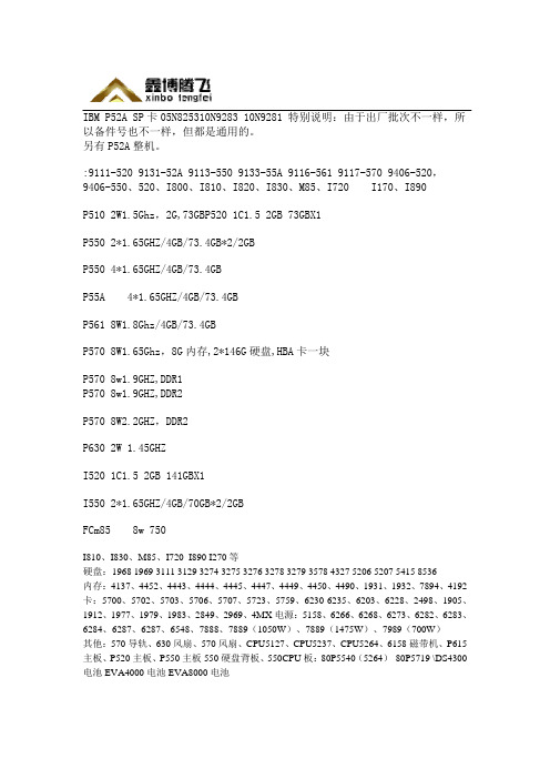
X3755 CPU 内存板 42D3093 44R5988 42D3097 40K7532 42D3108 P6 550 CPU 内存板
42R6609 44V3841 模块 44V6625 97P5095
IBM P570 7782 cpu 内存板 实物拍摄
? IBM X366 X260 X3800 CPU 板
42D3097
X365 散热片 FRU: 90P5046
3850M2 散热片
? COMPAQ PL3000 风扇 PL5000 风扇 Nhomakorabea
3650T 风扇 扇组
风
X340 风扇 X342 风扇 00N7248 20L1399 5000 风 扇
59P2572 风扇 X255 风扇
06p3609 百兆网卡
13N2195 6I 阵列卡
59p2952 X360 远程卡
39R8852 sas 卡 IBM 服务器 X250 X350 7600 CPU 终结板 10L6936 73p9246 IBM 远程控制卡
09N7292 IBM 光纤网卡
?
IBM P550 5264 CPU 内存板
07P6825
07P6793 46K8035 P6 550 CPU 内存板
42D3107 IBM X3755 CPU 内存板
P550 IBM 5264 CPU 内存板 1.5G 2-WAY
P6 570 CPU 内存板
46K6860 42R5983 42R5967 散热片
Sugatsune 玻璃支持硬件及配件说明书

SHELF & SUPPORT HARDWAREGLASS CLAMPSGLASS SHELF SUPPORTSSOAP HOLDERSBRACKETSMIRROR SUPPORTSGLASS STANDOFFSSHELF STANDARDS & ACCESSORIESSHELVING SYSTEMSMIRROR SUPPORTS PictureSMB-15RSPM-20BSP-1820(HEAVY DUTY)SPN-1820(NARROW PROFILE)496SPE-FB20S330lbs/4pcsSPHL-25SPN-15FSL-MBFSL-LSPN-17ECSPH-20SPH-5286lbs/4pcsSPH-1511lbs/pc SPB-35220lbs/4pcs 99lbs/4pcs 176lbs/4pcsSPF-20SPB-15R SPB-20SPW-20Item No.Glass Thickness (mm)Weight (g)Box (pcs)Carton (pcs) 9303VA21032410100Material Finish 316 Stainless Steel SatinItem No.Glass Thickness (mm)Weight (g)Box (pcs)Carton (pcs) 9344VA21022910100Material Finish316 Stainless Steel Satin • 316 stainless steel clamp.• F or flat surface.• O ptional Parts: 4820VA (Safety Pin)• S ee page 466 for load capacity.• T empered Glass Recommended.• 316 stainless steel clamp.• F or flat surface.• O ptional Parts: 9320VA (Safety Pin)4849VA (Safety Plate)• S ee page 466 for load capacity.• T empered Glass Recommended.GLASS CLAMP9303VA2 GLASS CLAMP9344VA2ZN1ZN1ZN5Item No.4846ZN14846ZN5GLASS CLAMPZN1ZN1ZN1 ZN54846ZN5 (P.463)Item No.Glass Thickness (mm)2878ST86~10MOUNTING SCREWMS7 MS15ZN1ZN5ZN1ZN5ZN1Item No.D LDSP-S/1212 (15/32")120 ( 4-45/64" ) DSP-S/1512 (15/32")150 ( 5-57/64" ) DSP-S/2012 (15/32")200 ( 7-55/64" ) DSP-M/1514 (35/64")150 ( 5-57/64" ) DSP-M/2014 (35/64")200 ( 7-55/64" ) DSP-M/2414 (35/64")240 ( 9-7/16" ) DSP-M/3014 (35/64")300 (11-51/64") DSP-L/2020 (25/32")200 ( 7-55/64" ) DSP-L/2520 (25/32")250 ( 9-53/64" )SU-B80/MSU-B65/MSU-B50/MXL-SA01-120/SXL-SA01-150/SXL-SA01-180/SXL-SA01-240/SStainless Steel WhiteBlackApplication ExampleEBDFolding BracketDamper unit477.21-3/16"(30 mm)12-1/2" (317 mm)P1*6-3/4" (171 m m )1/16"(2 m m )15/16"(24 m m )2-5/8"(67 m m )1-3/4"(45 m m )1-1/2"(38 m m )6-1/8" (156 mm)3-7/8"(98 mm)1-7/16"(36 mm)1-7/16"(36 m m )FOLDING BRACKET WITH SOFT-CLOSETo find your Min./Max. table weight per single damper, please reference the formula shown next to the charts above and 18” depth examples below.EB-303/EP-DMaximum weight 7.2 lbs = 130/18 in.Minimum weight 2.8 lbs = 52/18 in.EB-317/EP-DMaximum weight 19.1 lbs = 345/18 in.Minimum weight 12.5 lbs = 225/18 in.Stainless SteelBlackTT EB-317/EP-D• A utomatically locks when flap is in open position.• P ress lever to release the lock.• A dditional hinges not required.• D amper unit with a soft-closing feature which makes bracket smoother and safer.• R efer to DAMPER WEIGHT CHART below for appropriate table weight and depth when softly folding down the table. • F or panel thickness 9/16" ~ 1-3/8" (15 ~ 35 mm).• D urability tested 50,000 cycles (private).Side Levers Connecting RodSafety Lock ScrewHolding BracketSpringConnecting LeverFor EB-2000-3 onlyNo.Part Name Material Finish1Connecting LeverAluminum AnodizedAluminum 2Side Lever3Spring Stainless Steel4Washer Plastic5Holding BracketAluminum AnodizedAluminum 6Connecting RodStainless Steel477.4Item No.Rod QtyRod Length (L)Side Lever QtySafety Lock QtyHolding Bracket QtySpring QtyEB-1000-2139-3/8" (1000 mm)2131EB-1500-2159-1/16" (1500 mm)2131Item No.Rod QtyRod Length (L)Side Lever QtyConnecting Lever QtySafety Lock Qty Holding Bracket Qty Spring QtyEB-2000-3239-3/8" (1000 mm) each 21161Connecting LeverLEVER RELEASE FOR EB SERIES FOLDING BRACKETSLEVER RELEASE for EB Folding Bracket LEVER RELEASE for EB Folding Bracket EB-1000-2/1500-2EB-2000-3SHELF & SUPPORT HARDWARERecommended Hinge: 388H38830-25-DDamper388HDo not lift up the shelf forcibly. It may result in breakage.Z058* S pecial wrench Z058 required for installation. (Sold Separately)Cut Out DimensionCut Out DimensionMaterialFinish 302 Stainless Steel/Aluminum SatinItem No.Glass Thickness (mm)Weight (g)Box (pcs)Carton (pcs)7005VA 8~12192440MaterialFinish 302 Stainless Steel/Aluminum SatinItem No.Glass Thickness (mm)Weight (g)Box (pcs)Carton (pcs)7000VA 8~12167440Z058• F lush mount type glass standoff.• R ecommended Screw Size: M8 bolt • L onger base 80~180 mm (3-5/32"~7-3/32") available as special order.• R ecommended for use with tempered glass.* S pecial wrench Z058 required for installation. (Sold Separately)• G lass standoff with round face plate.• R ecommended Screw Size: M8 bolt • L onger base 80~180 mm (3-5/32"~7-3/32") as special order.• R ecommended for use with tempered glass.GLASS STANDOFF 7000VAGLASS STANDOFF 7005VAItem No.Glass Thickness (mm) Item No.Glass Thickness (mm) 7015VA8~12Item No.Glass Thickness (mm)7061VA6~12GLASS STANDOFF Item No.Glass Thickness (mm)7062VA6~12Z057* S pecial wrench Z057 required for installation. (Sold Separately)Item No.Glass Thickness (mm)7083VA 6~12Finish GLASS STANDOFFItem No.Glass Thickness (mm)7120VA8GLASS STANDOFFSMB-15RSPM-20BSP-1820(HEAVY DUTY)SPN-1820(NARROW PROFILE)496SPE-FB20S330lbs/4pcsSPHL-25SPN-15FSL-MBFSL-LSPN-17ECSPH-20SPH-5286lbs/4pcsSPH-1511lbs/pc SPB-35220lbs/4pcs 99lbs/4pcs 176lbs/4pcsSPF-20SPB-15R SPB-20SPW-20Item No.Item No.Load Capacity (kg)SPH-15130 (286 lbs)/4 pcs END CAPWeight (g)1.3StandardAP-DM1820WT AP-DM1820AP-DH1820Item No.D E Weight (g)AP-DM1820178017113 AP-DM1820WT AP-DM1820BL AP-DM2600250047161 AP-DH1820178017131 AP-DH2600250047187Item No.Screw TypeAP-SC3-16 AP-SC3-16WT AP-SC3-16BL AP-SC3-30 AP-SC3-30WT AP-SC3-30BL • A luminum shelf standard.• E asy to cut to desired length.• T hin profile (3 mm, 1/8") suitable for surface mount.• S crew hole located every 120 mm (4-23/32").• N ew slot shape to prevent shelf support from falling off.• S pecial screw with silver finish available. (AP-SC3-16)• S crews and accessories sold separately.• A luminum shelf standard.• E asy to cut to desired length.• D esigned for press-fit mount without using screws.• N ew slot shape to prevent shelf support from falling off.• S crews and accessories sold separately.* Install the standard with concave slot(located every 120 mm) pointing upward.* Fit tightness may vary depending on the panel/wall material. Use adhesive if loose.Bore Dimension (In case of Plywood)SHELF STANDARDHolds in any height。
电子CAD绘制U盘原

NC NC NC NC I/O7 I/O6 I/O5 I/O4 NC NC NC VCC VSS NC NC NC I/O3 I/O2 I/O1 I/O0 NC NC NC NC
48 47 46 45 44 43 42 41 40 39 38 37 36 35 34 33 32 31 30 29 28 27 26 25
选择原理图工具中的 工具,按下键盘上的 【Tap】键,弹出网络标 号属性对话框,如图所 示,在【Net】栏输入 “SM-ALE”,可以点击 【Font】栏的 【Change…】按钮。改 变文字的字体和大小,点 击【OK】按钮完成设置
3. 添加网络标号属性
光标变为十字型,并且带出网络标号 “SM-ALE”,将光标移动到要添加网络 标号的导线上,此时导线上出现黑色小 十字型电气节点,如图所示,单击鼠标 左键即可放置该网络标号。
PC2 24 PA_WE 23
P30 22 P47 21 P14 20 P46 19 X_WRN 18 X_RDN 17 PC1 16 X_A1 15 X_A0 14 P32 13
1 VCCF 2 VSS 3 RST 4 VCCF 5 VSSF 6 TM1 7 TM2 8 PB4 9 X_INTRQ 10 PC0 11 PB5 12 P31
3
2
P11
1
SW1
C12 10uF
C13 0.1uF
U1 1 Vin
Vout 5
2 GND
3 Cont
NDIS 4
AT1201
VCC
C14 4.7uF
C15 0.01uF
VCC
C1 0.1uF
C2
C3
C4
C5
C6
0.1uF 0.1uF 0.1uF 0.1uF 0.1uF
CORONA 2.4GHz Spread Spectrum (FASST COMPATIBLE) R

CORONA 2.4GHz Spread Spectrum (FASST COMPATIBLE)Receiver Instruction Manual for R4FA‐SB and R6FA‐SB Compatibility:The CORONA 2.4GHz Spread Spectrum FASST Compatible Receiver is designed for use with FUTABA’s FASST 2.4GHz transmitters; including the 3PM,3PKS,3VCS,3GR,4PK(S),TM7, TM8, TM10, TM14 and the T6EX‐2.4G, 7C‐2.4G, 8FG, 10CG, 12FG. The R4FA‐SB and R6FA‐SB receivers supply a more useful mode for users. Both the R4FA‐SB and R6FA‐SB support FUTABA’s FASST air system and surface system. The R4FA‐SB supports 7‐channel with continuous PPM (positive and negative) output ,RSSI output and S.BUS output, R6FA‐SB supports 6 channel high speed PPM(HS) mode to optimize helicopter response control and S.BUS output.Under S.BUS output mode, both R4FA‐SB and R6FA‐SB supply 12 proportional channels and 2 DG channels. Therefore, the R4FA‐SB or R6FA‐SB becomes 14‐channel receivers when using S.BUS output.Specifications:Operating Current: 50mA maxOperating Voltage: 3.6 ~10VLatency: R4FA‐SB’s description14mS for independent 4 channel output and S.BUS output @ FASST multi‐channel mode21mS for Continuous PPM output and RSSI output@ FASST multi‐channel mode16mS for independent 4 channel output and S.BUS output @ FASST 7ch mode24mS for Continuous PPM output and RSSI output@ FASST 7ch mode14mS for independent 3 channel output@ FASST surface system C1 CODE modeR6FA‐SB’s description7mS for independent 6 channel (HS) output@ FASST multi‐channel mode14mS for independent 7 channel (LS) output and S.BUS output @ FASST multi‐channel mode 8ms for independent 6 channel (HS) output@ FASST 7ch mode16mS for independent 7 channel (LS) output and S.BUS output @ FASST 7ch mode14ms for independent 3 channel output@ FASST surface system C1 CODE modeSensitivity: about ‐100dBmOperation temperature:‐10~80 deg CSetup:Bind procedure:∙Turn on the FASST transmitter∙Connect the battery to the receiver while pressing the receiver’s F/S button.∙The Dual‐color LED’s will continuously cycle through the following:o Red LED light (searching radio signal)o Green LED light (acquired the radio signal)o Red LED off (bind ok)o Green LED flashes 10 times (ID stored in memory)o Green LED lights solid (normal operation)Note: FASST surface systems take a bit more time to complete the bind procedure.Fail‐safe setting:There are two ways to set the Failsafe setting on the CORONA 2.4GHz Spread Spectrum FASST Compatible Receiver;1.TX‐failsafe feature: This method sets the failsafe on the FASST transmitter and has priority (works onchannel 3 only under FASST 7ch mode or on multiple‐channels under FASST multi‐channel mode) while the receiver is on, just like FUTABA receivers (only available on FASST air system).2.RX‐failsafe feature: Turn on the FASST transmitter and then turn on the CORONA 2.4GHz Spread SpectrumReceiver, put all the sticks and switches to control inputs you want if the receiver looses signal and Press the F/S button down for about 5 ‐ 6 seconds while the Green LED lights solid (Rx in normal operation), then release the button. You will see the Red LED will flash for about 4 ‐ 5 seconds. (Note: The Red LED will FLASH high speed to indicate the RX‐failsafe is turned on OR FLASH low speed to indicate the RX‐failsafe is turned off). If you press the F/S button a second time while the Red LED is flashing, the receiver will change its RX‐failsafe status (on / off), then the LED will return to Green solid again. If you not press the F/S button, nothing will be changed and the LED will return to solid Green. If you want to cancel the RX‐failsafe feature (not just turn it off), you can do so by binding the receiver again. After binding operation the receiver will be back to factory settings without any failsafe feature.Note: If you do not set a failsafe setting, the receiver will hold all controls at the position of the last command received before signal was lost. When RX‐failsafe is turned on, the receiver will initiate the RX‐failsafe settings after loosing signal for over 1 second and the receiver will hold the last received positions until the failsafe takes over. When the RX‐failsafe and TX‐failsafe feature are both turned on, the receiver will use the TX‐failsafe command.We highly recommend you set failsafe feature before flying your models. An example of a minimal useful, failsafe setting would be to shut down the model’s throttle, so that it does not fly or drive away uncontrolled.Output mode setting (only available on FASST air system):Turn off the transmitter, connect the battery to the receiver, you will see the Red LED light flashing. The RED LED flashes at high speed to indicate the receiver is in the special output mode OR a Low speed indicates the receiver is under (LS) low speed PPM normal output mode, press the F/S button for 5‐6 seconds while the Green LED is off (Rx in signal searching status), then release the button. You will see the Green LED flash for about 4 ‐ 5 seconds. (Note: The Green LED will FLASH high speed under special mode OR FLASH low speed under normal output mode). If you press the F/S button a second time while the Green LED is flashing, the receiver will change its output mode status (special/normal), if you do not press the F/S button the output mode will not be changed and the Red LED will flash at its original speed.Note: Output mode function is described in the form below,R4FA‐SB R6FA‐SBnormal Ch1~CH4 independent PPM output normal Ch1~CH7 independent PPM outputCH1 Neg CPPM out(FUTABA trainer FUNC)^1 CH2 Pos CPPM out for special user^2 CH1~CH6 independent high speed(HS)PPM out for helicopter fast response controlCH3 RSSI PWM out for FPV()^3 specialCH4 S.BUS output for compact system specialCH7 S.BUS output for compact systemNote: ^1 refer the signal description picture below^2 refer the signal description picture below^3 refer the signal description picture belowRSSI PWM out define: Pulse width from about 900uS~ 2100uS to indicate RSSI strength from ‐100dBm~‐40dBm.Important Note: If you are using analog servos in your model you must keep your receiver under the factory settings (normal output mode) or your analog servo will get hot and possibly burn out. As well you cannot use a non S.BUS servo on a channel while S.BUS signal output present.LED status indicated under normal working status:RED LED GREEN LED Statusflash off No signal searchedoff solid Signal is very goodSometime flash solid Signal is not very goodflash flash Signal is weak。
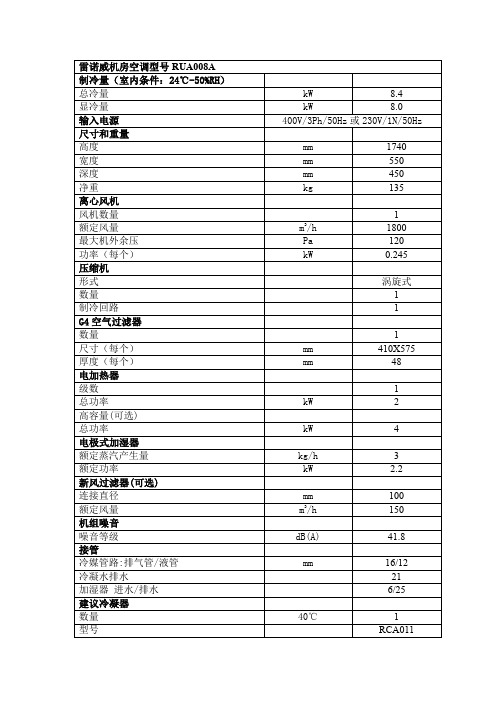
雷诺威机房空调型号参数RUA008A
mW mm m3/h dB(A) mm
40℃
数量 型号
45℃
1 RCA013
kW 8.4 kW 8.0 400V/3Ph/50Hz 或 230V/1N/50Hz mm mm mm kg 1740 550 450 135 1 1800 120 0.245 涡旋式 1 1 1 410X575 48 1 2 4 3 2.2 100 150 41.8 16/12 21 6/25 1 RCA011
雷诺威机房空调型号 RUA008A 制冷量(室内条件:24℃-50%RH) 总冷量 显冷量 输入电源 尺寸和重量 高度 宽度 深度 净重 离心风机 风机数量 额定风量 最大机外余压 功率(每个) 压缩机 形式 数量 制冷回路 G4 空气过滤器 数量 尺寸(每个) 厚度(每个) 电加热器 级数 总功率 高容量(可选) 总功率 电极式加湿器 额定蒸汽产生量 额定功率 新风过滤器(可选) 连接直径 额定风量 机组噪音 噪音等级 接管 冷媒管路:排气管/液管 冷凝水排水 加湿器 进水/排水 建议冷凝器 数量 型号
机房和施工组织模板
江西新昌电厂“上大压小〞新建工程厂级管理信息系统〔MIS〕网络及硬件平台系统集成投标文件投标编号:03-ct-03-2007-156〔第三卷附件1-技术标准书〕投标人:安徽科大恒星电子商务技术二00九年四月目录第一章概述 (1)工程建设需求 (1)设计原那么 (2)实用性与先进性相结合 (2)可扩展性和开放性 (2)可靠性和平安性 (3)可管理性 (3)设计、施工标准 (3)工程建设目标 (6)第二章效劳器系统平台设计 (7)建设需求 (7)数据库效劳器设计 (7)IBM power550方案 (7)效劳器选型 (7)2.2.1.2 IBM Power 550配置 (12)HP 小型机方案 (13)效劳器选型 (13)2.2.2.2 HP Integrity rx6600 配置 (17)系统运行模式设计 (17)并行处理模式 (18)任务分担模式 (18)主机备用模式 (18)其它效劳器设计 (18)效劳器的部署 (18)物理效劳器与逻辑效劳器之间的关系 (19)效劳器选型设计 (20)2.3.3.1 IBM X3850 M2方案 (20)2.3.3.2 HP ProLiant DL580 G5 效劳器方案 (23)效劳器配置 (26)2.3.4.1 IBM X3850 M2配置 (26)2.3.4.2 HP ProLiant DL580 G5配置 (27)SAN存储系统设计 (27)2.4.1 IBM TotalStorage DS4800方案 (28)2.4.1.1 IBM TotalStorage DS4800介绍 (28)2.4.1.2 TotalStorage DS4800配置 (31)2.4.2 HP StorageWorks EVA8100方案 (32)2.4.2.1 HP StorageWorks EV A8100介绍 (32)2.4.2.2 HP StorageWorks EV A8100配置 (35)光纤交换机选型 (36)2.4.3.1 IBM System Storage SAN2005-B16 特性 (36)2.4.3.2 IBM System Storage SAN2005-B16 配置 (38)数据备份系统 (38)数据备份需求 (38)数据备份方案 (39)2.5.2.1 Veritas的优势 (39)2.5.2.2 Veritas配置 (42)磁带库选型配置 (43)虚拟磁带库选型 (44)第三章网络系统平台设计 (49)网络建设需求 (49)网络拓扑结构设计 (49)分层设计 (49)可靠性保证〔冗余设计〕 (49)网络拓扑实现 (50)核心层设计 (51)接入层设计 (51)远程访问层设计 (51)Cisco解决方案 (51)中心交换机选型 (51)3.3.1.1 Cisco® 6500介绍 (52)3.3.1.2 Supervisor Engine 720 (56)3.3.1.3 Cisco Catalyst 6513配置 (58)接入交换机选型 (59)H3C解决方案 (59)中心交换机选型 (59)H3C S7500E介绍 (60)H3C S7510E配置 (63)接入交换机选型 (63)第四章系统平安设计 (65)系统平安需求 (65)系统平安体系结构 (65)物理设备平安 (65)访问平安 (66)应用平安 (66)数据平安 (66)平安策略 (67)传输通道和传输设备平安 (67)应用平台平安 (68)资源访问平安 (68)网络防病毒 (69)多功能防火墙设计 (70)HillstoneSA-5020介绍 (71)HillstoneSA-5020功能规格 (72)内网核心平安防护系统〔主机加固〕设计 (74)S-NUMEN用途 (74)S-NUMEN功能 (75)S-NUMEN配置 (76)内网主机审计及监管系统 (76)系统功能 (77)系统特点 (79)体系架构 (80)配置 (81)防病毒系统设计 (81)网络防病毒配置 (84)第五章综合布线系统设计 (85)综合布线系统需求 (85)设计标准与设计目标 (85)设计标准 (85)设计目标 (86)布线系统设计 (86)光缆敷设 (86)SAN光纤走向 (86)布线系统测试 (87)测试标准与内容 (89)提交文档 (94)第六章工程组织与管理 (95)工程管理与目标 (95)工程组织及人力资源分配 (96)施工组织总体部署 (96)人力资源配置 (98)与相关单位合作 (99)与工程单位合作 (99)与厂商合作 (100)工程管理 (100)管理方法 (100)管理措施 (101)工程风险管理 (104)工程进度管理 (104)工程质量控制与保证 (105)工程阶段性评估 (106)第七章工程实施方案 (107)工程实施环节规划 (107)实施环节规划总表 (107)设计联络 (109)设备订货及到货 (110)实施现场情况调研 (110)制定详细实施方案 (111)培训 (111)设备验收 (111)查验设备 (111)查验方法 (112)查验报告 (117)系统安装调试 (117)系统调试方案制定 (117)小型机调试 (118)中心交换机调试 (118)边缘交换机调试 (118)中心路由器调试 (119)网管软件调试 (119)主机调试 (119)备份系统调试 (120)系统初验收 (120)试运行 (120)技术文档的提交 (121)系统终验 (121)技术支持与售后效劳 (121)实施进度方案 (121)里程碑事件及考核标准 (122)第八章验收方案与文档 (123)验收测试内容 (123)现场验收测试 (124)文档验收 (126)系统初验收 (126)系统终验 (127)测试方案 (127)测试方法 (127)测试工程 (127)测试方法 (128)工程文档 (129)工程文档内容 (129)工程文档提交方案 (132)第九章机房建设工程 (134)工程简述 (134)电子计算机机房组成及使用面积确定 (134)可维护性设备布置 (135)设计原那么 (135)计算机机房平安分类 (135)建设标准 (137)设计依据 (138)设计依据 (138)设计指标 (140)机柜及机房隔断、装饰设计 (141)机柜 (141)图腾机柜概述 (141)图腾机柜选型 (141)机房隔断 (141)装饰设计 (142)装修材料选材 (142)材料表 (143)吊顶 (143)地面 (144)墙、柱面 (145)门、窗 (145)供配电系统〔含UPS、照明等〕 (146)电气概述 (146)供配电系统 (147)设计标准要求 (147)9.5.2.2 机房配电冗余供电系统 (149)配电设备 (149)UPS系统 (149)UPS选型选型 (149)艾默生“UL33〞系列UPS性能参数 (150)美国“艾默生〞系列UPS特点 (151)电池配置 (151)照明系统设计 (152)普通照明系统设计 (153)应急照明、疏导灯具系统设计 (153)配电线路安装技术 (153)空调系统 (154)空调系统设计 (154)空调设备选型 (154)防雷接地 (154)防雷系统概述 (154)对雷电引入的分析 (155)机房防雷设计 (156)防雷验收及保障 (156)接地系统概述 (156)接地系统解决措施 (157)机房的地线系统 (157)局部等电位连接 (157)抗静电保护地 (157)静电防护 (158)KVM设备及机房布线 (158)KVM设计需求 (158)KVM设计方案说明 (159)环境监控、消防报警及其他相关效劳 (159)环境监控 (159)门禁系统 (159)视频监控 (159)动力环境监控 (159)消防报警 (160)9.9.3 控制台桌椅 (161)灾害处理 (161)机房区防水防护措施 (161)机房给水排水技术 (161)防虫、防鼠害 (162)电磁屏蔽 (162)第一章概述江西新昌电厂网络及硬件平台系统集成工程建设主要包括了网络系统、无线网络覆盖、效劳器系统、存储系统、数据备份系统、微软AD域设计及网络部署、管理及系统软件、MIS终端、智能机房、综合布线等系统,按现代先进技术设计,该系统集成完成后,新昌电厂具有统一的生产MIS系统运行平台,能为其信息化建设提供良好的根底效劳。
威森特常规产品报价
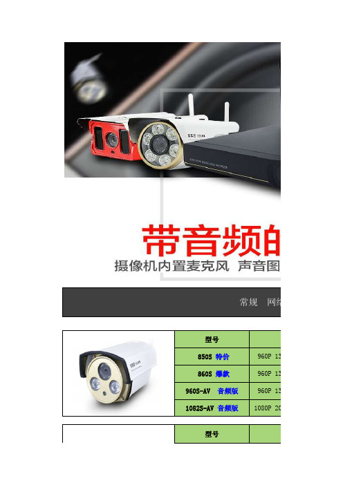
对每个常规 网络摄型号分850S 特价960P 130万860S 爆款960P 130万960S-AV 音频版 960P 130万华为海思1082S-AV 音频版1080P 200万型号分2501S (H.265)06SE 960P 9003(捷安锐视)1080P1300S 960P1185S 星光全彩1080P日夜全彩 白光摄像机1600S1080P 9200S 1080P型号分型号分6130S-AV 音频版960P 6200S-AV 音频版1080P 3MP型号分 1086S 推荐1080P 200万型号分5130S960P 861S960P 130万 862S 爆款960P 130万 1083S1080P 200万2506S (H.265)智能球形变倍一体机特殊场合 网络红激光 夜视王7621S 1080P 型号分型号分7613S960P 7620S1080P Q1960P 1305倍Q2 1080P 2 5倍Q3 1080P 2 25倍3MP型号分特点:室内室外防雨 4.5寸迷你球机 6颗阵列红外灯 5倍支持360度旋转 支持预置位 支持手机远程控制、手机录像。
可无线连4.5寸迷你球道路车牌摄像机防爆摄像机防爆摄像机电梯专用摄像机银行专用摄像机2081S 全彩低照度1080P 2061S 全彩低照度1080P 型号分2080S1080P 6203S 音频版3MP 型号分2060S960P 型号分 6201S 音频版1080P 6202S 音频版1080P 6003S960P 6013S 1080P6033S1080P L6001080P L7001085P型号分L500960P9615AH AHD同轴960P 9610AH AHD同轴9196AH AHD同轴960P960P9612AH AHD同轴960P2000HD 模拟005HK 模拟81000TVL 605HD 模拟1000TVL型号分型号分型号分型号分模拟摄像机 AHD同型号分9660AH AHD同轴960P 7118HD 模拟812路 NVR 型号Smart-916S 16路画面显示 支持1块硬模式1:接入16路108支持自组网一键添加 ,支持音频输出 可接音响耳机 即插即用,型号Smart-912S 12路画面显示,支持1块硬模式1:接入12路96模式2:接入9路108支持音频输出 可接音响耳机 即插即用,NVR网络录像型号Smart-904S 6路画面显示,支持1块硬支持 接入6路1080支持自组网一键添加 ,支持音频输出 可接音响耳机 即插即用,型号Smart-906S 6路画面显示,支持1块硬6路 NVR 4路 NVR 支持 接入6路108025路 NVR 4路 混合录像机16路 NVR 36路 NVR 4盘位即插即用,一键远程4合一 混合硬盘型号:6804S 4路画面显示,支持1块硬盘同时支持模拟摄像机、AH支持自组网一键添加 ,即插即用,一键支持自组网一键添加 ,支持音频输出 可接音响耳机 即插即用,型号Smart-936S 36路画面显示,支持4块硬模式1:接入36路96模式2:接入35路108型号:6808S 8路画面显示,支持1块硬盘同时支持模拟摄像机、AH即插即用型号Smart-925S 25路画面显示,支持2块硬模式1:接入25路108H.265 NVR录像机 4路 H.265 NVR 8路 混合录像机16路 混合录像机32路 混合录像机支持V390全景摄像机 多种模式显示 支持自型号:9804S 4路画面显示,支持1块硬盘存储减半 最高支持支持V390全景摄像机 多种模式显示 支持自即插即用,一键型号:9808S 8路画面显示,支持1块硬盘存储减半 最高支持支持自组网一键添加 ,即插即用,一键型号:6632S 32路画面显示,支持4块硬盘同时支持模拟摄像机、AH支持自组网一键添加 ,即插即用,一键即插即用,一键型号:6616S 16路画面显示,支持2块硬盘同时支持模拟摄像机、AHPOE 网络监一根网络线 同时传输电源与信号8路 H.265 NVR 32路 H.265 NVR 16路 H.265 NVR 一根网络线 同时传输电源无需交换机、无需电源线型960P 130万华为海思方案一根网络线 同时传输电源型号:9832S 32路画面显示,支持4块硬盘存储减半 最高支持支持V390全景摄像机 多种模式显示 支持自即插即用,一键型960P 130万华为海思方案即插即用,一键型号:9816S 8路画面显示,支持1块硬盘存储减半 最高支持支持V390全景摄像机 多种模式显示 支持自即插即用,一键全景 网络监一台顶多台 全方位无死角监控 同步录音录4路 POE NVR 8路 POE NVR 型号:3 300万像素支持语音对讲 远程监最大支持128G TF卡共计9个网口 8个网口支持2块硬盘,型号:1200万像素支持语音对讲 远程监最大支持128G TF卡内置拾音器,V6方型4路画面显示 接入最大4共计5个网口 4个网口无需交换机 支型8路画面显示接入 最大8无需交换机、无需电源线免布线 电力网络一根电力线 同时传输多个摄像机 最远60 农行卡号:622 849 06300 1210 9510 户名:孙恒 邮政新卡号: 622 188 12100 2364 9705 户名:孙恒资中行:6216 615 00000 2408 071 户名:孙恒资工商:6222 08040 20014 07068 户名:孙恒资 开户行:中华 建行:4367 4201 3039 8652 954 户名:孙恒资支付宝:136******** 孙国强 以上报价不含税票及运费 (公司可开增全景专用 8路NVR 全景专用 4路NVR 最高可接入4路5M支持HDMI输出 即插即用,一键远型号 9808 8路画面显示,支持1块硬盘支持2分割画面、4分最高可接入8路5M支持HDMI输出 即插即用,一键远内置拾音器,V6方型号 9804 4路画面显示,支持1块硬盘支持2分割画面、电力网络传可实现电力猫功省去交换机、电源线、网支持任何品牌网络电力需配合 电力网络传省去交换机、电源线、网支持任何品牌网络10台起 价格69元76元100元12610台起 价格网络摄像机V6方案 H.264压缩格式全铝合金结构 75口径2颗晶元点阵红外灯最远夜视距离50米以上性能130万像素 华为海思200万像素 华为海思分辨率分辨率性能 130万像素 国科芯片130万像素 V6AK芯片全铝合金结构 100口径机机195元机机130元220元VIP价格60元75元力猫功能 同电表内 多个使用线、网线、监控电源、防水盒一半人工费牌网络NVR录像机、网络IPC摄像机电力网络接收器网络传输器 (发射器 )。
Motorola 3.5 kHz 产品说明书

RVN4126 3.59100-386-9100-386/T DEVICERVN41772-CD2-3.5MCS/MTSRVN41821-CD2-3.5XTS3000/SABER PORTABLE YES RKN4046KHVN9085 3.51-20 R NO HLN9359 PROG. STAND RVN4057 3.532 X 8 CODEPLUG NO3080385B23 & 5880385B30 MDVN4965 3.59100-WS/T CONFIG KITRVN4053 3.5ASTRO DIGITAL INTERFACE NO3080385B23RVN41842-CD RKN4046A (Portable) 2-3.5ASTRO PORTABLE /MOBILE YES3080369B73 or0180300B10 (Mobile) RVN41831-CD3080369B732-3.5ASTRO SPECTRA MOBILE YES(Low / Mid Power)0180300B10 (High Power) RVN4185CD ASTRO SPECTRA PLUS MOBILE NO MANY OPTIONS; SEESERVICE BRIEF#SB-MO-0101RVN4186CD ASTRO SPECTRA PLUS MANY OPTIONS;MOBILE/PORTABLE COMB SEE SERVICE BRIEF#SB-MO-0101RVN4154 3.5ASTROTAC 3000 COMPAR.3080385B23RVN5003 3.5ASTROTAC COMPARATORS NO3080399E31 Adpt.5880385B34RVN4083 3.5BSC II NO FKN5836ARVN4171 3.5C200RVN4029 3.5CENTRACOM SERIES II NO VARIOUS-SEE MANUAL6881121E49RVN4112 3.5COMMAND PLUS NORVN4149 3.5COMTEGRA YES3082056X02HVN6053CD CT250, 450, 450LS YES AAPMKN4004RVN4079 3.5DESKTRAC CONVENTIONAL YES3080070N01RVN4093 3.5DESKTRAC TRUNKED YES3080070N01RVN4091 3.5DGT 9000 DESKSET YES0180358A22RVN4114 3.5GLOBAL POSITIONING SYS.NO RKN4021AHVN8177 3.5GM/GR300/GR500/GR400M10/M120/130YES3080070N01RVN4159 3.5GP60 SERIES YES PMLN4074AHVN9128 3.5GP300 & GP350RVN4152 3.5GP350 AVSRVN4150 3.5GTX YES HKN9857 (Portable)3080070N01(Mobile) HVN9025CD HT CDM/MTX/EX SERIES YES AARKN4083/AARKN4081RiblessAARKN4075RIBLESS NON-USA RKN4074RVN4098H 3.5HT1000/JT1000-VISAR YES3080371E46(VISAR CONV)RVN4151 3.5HT1000 AVSRVN4098 3.5HT1000/ VISAR CONV’L.YES RKN4035B (HT1000) HVN9084 3.5i750YES HLN-9102ARVN4156 3.5LCS/LTS 2000YES HKN9857(Portable)3080070N01(Mobile) RVN4087 3.5LORAN C LOC. RECV’R.NO RKN4021ARVN4135 3.5M100/M200,M110,M400,R100 includesHVN9173,9177,9646,9774YES3080070N01RVN4023 3.5MARATRAC YES3080070N01RVN4019 3.5MAXTRAC CONVENTIONAL YES3080070N01RVN4139 3.5MAXTRAC LS YES3080070N01RVN4043 3.5MAXTRAC TRK DUPLEX YES3080070N01RVN4178CD MC SERIES, MC2000/2500DDN6124AW/DB25 CONNECTORDDN6367AW/DB9 CONNECTOR RVN41751-CD Rib to MIC connector 1-3.5MCS2000 RKN4062BRVN41131-3.5MCS2000RVN4011 3.5MCX1000YES3000056M01RVN4063 3.5MCX1000 MARINE YES3000056M01RVN4117 3.5MDC/RDLAP DEVICESRVN4105 3.5MOBILE PROG. TOOLRVN4119 3.5MOBITEX DEVICESRVN4128 3.5MPT1327-1200 SERIES YES SEE MANUALRVN4025 3.5MSF5000/PURC/ANALOG YES0180355A30RVN4077 3.5MSF5000/10000FLD YES0180355A30RVN4017K 3.5MT 1000YES RTK4205CRVN4148 3.5MTR 2000YES3082056X02RVN4140 3.5MTRI 2000NORVN41761-CD MTS2000, MT2000*, MTX8000, MTX90001-3.5*programmed by DOS which is included in the RVN4176RVN4131 3.5MTVA CODE PLUG FIXRVN4142 3.5MTVA DOCTOR YES3080070N01RVN4131 3.5MTVA3.EXERVN4013 3.5MTX800 & MTX800S YES RTK4205CRVN4097 1-CD MTX8000/MTX9000,MTS2000,MT2000*,* programmed by DOS which is included in the RVN4176HVN9067CD MTX850/MTX8250MTX950,MTX925RVN4138 3.5MTX-LS YES RKN4035DRVN4035 3.5MX 1000YES RTK4203CRVN4073 3.5MX 800YES RKN4006BHVN9395 P100, P200 LB, P50+, P210, P500, PR3000RVN4134 3.5P100 (HVN9175)P200 LB (HVN9794)P50+ (HVN9395)P210 (HVN9763)P500 (HVN9941)PR3000 (HVN9586)YES RTK4205HVN9852 3.5P110YES HKN9755A/REX1143 HVN9262 3.5P200 UHF/VHF YES RTK4205RVN4129 3.5PDT220YVN4051 3.5PORTABLE REPEATER Portable rptr.P1820/P1821AXRVN4061C 3.5PP 1000/500NO3080385B23 & 5880385B30 RVN5002 3.5QUANTAR/QUANTRO NO3O80369E31RVN4135 3.5R100 (HVN9177)M100/M200/M110/M400YES0180358A52RVN4146 3.5RPM500/660RVN4002 3.5SABER YES RTK4203CRVN4131 3.5SETTLET.EXEHVN9007 3.5SM50 & SM120YESRVN4039 3.5SMART STATUS YES FKN5825AHVN9054 3.5SOFTWARE R03.2 P1225YES3080070N01HVN9001 3.5SOFTWARE R05.00.00 1225LS YES HLN9359AHVN9012 3.5SP50RVN4001N 3.5SPECTRA YES3080369B73 (STANDARD)0180300B10 (HIGH POWER) RVN4099 3.5SPECTRA RAILROAD YES3080369B73RVN4110 3.5STATION ACCESS MODULE NO3080369E31RVN4089A 3.5STX TRANSIT YES0180357A54RVN4051 3.5SYSTEMS SABER YES RTK4203BRVN4075 3.5T5600/T5620 SERIES NO3080385B23HVN9060CD TC3000, TS3000, TR3000RVN4123 3.5VISAR PRIVACY PLUS YES3080371E46FVN4333 3.5VRM 100 TOOLBOX FKN4486A CABLE &ADAPTORRVN4133 3.5VRM 500/600/650/850NORVN4181CD XTS 2500/5000 PORTABLES RKN4105A/RKN4106A RVN41002- 3.5XTS3000 ASTRO PORTABLE/MOBILERVN4170 3.5XTS3500YES RKN4035DRIB SET UPRLN4008E RADIO INTERFACE BOX (RIB)0180357A57RIB AC POWER PACK 120V0180358A56RIB AC POWER PACK 220V3080369B71IBM TO RIB CABLE (25 PIN) (USE WITH XT & PS2)3080369B72IBM TO RIB CABLE (9 PIN)RLN443825 PIN (F) TO 9 PIN (M) ADAPTOR (USE W/3080369B72 FOR AT APPLICATION) 5880385B308 PIN MODULAR TO 25 PIN ”D” ADAPTOR (FOR T5600 ONLY)0180359A29DUPLEX ADAPTOR (MOSTAR/TRAXAR TRNK’D ONLY)Item Disk Radio RIB Cable Number Size Product Required Number Item Disk Radio RIB Cable Number Size Product Required NumberUtilizing your personal computer, Radio Service Software (RSS)/Customer Programming Software (CPS)/CustomerConfiguration Software (CCS) enables you to add or reprogram features/parameters as your requirements change. RSS/CPS/CCS is compatible with IBM XT, AT, PS/2 models 30, 50, 60 and 80.Requires 640K RAM. DOS 3.1 or later. Consult the RSS users guide for the computer configuration and DOS requirements. (ForHT1000, MT/MTS2000, MTX838/8000/9000, Visar and some newer products —IBM model 386, 4 MEG RAM and DOS 5.0 or higher are recommended.) A Radio Interface Box (RIB) may be required as well as the appropriate cables. The RIB and cables must be ordered separately.Licensing:A license is required before a software (RVN) order is placed. The software license is site specific (customer number and ultimate destination tag). All sites/locations must purchase their own software.Be sure to place subsequent orders using the original customer number and ship-to-tag or other licensed sites; ordering software without a licensed customer number and ultimate tag may result in unnecessary delays. To obtain a no charge license agreement kit, order RPX4719. To place an order in the U.S. call 1-800-422-4210. Outside the U.S., FAX 847-576-3023.Subscription Program:The purchase of Radio ServiceSoftware/Customer Programming/Customer ConfigurationSoftware (RVN & HVN kits) entitles the buyer/subscriber to three years of free upgrades. At the end of these three years, the sub-scriber must purchase the same Radio Service Software kit to receive an additional three years of free upgrades. If the sub-scriber does not elect to purchase the same Radio Service Software kit, no upgrades will be sent. Annually a subscription status report is mailed to inform subscribers of the RSS/CPS/CCS items on our database and their expiration dates.Notes:1)A subscription service is offered on “RVN”-Radio Service Software/Customer Programming/Customer Configuration Software kits only.2)“RVN” software must only be procured through Radio Products and Services Division (RPSD). Software not procured through the RPSD will not be recorded on the subscription database; upgrades will not be mailed.3)Upgrades are mailed to the original buyer (customer number & ultimate tag).4)SP software is available through the radio product groups.The Motorola General Radio Service Software Agreement is now available on Motorola Online. If you need assistance please feel free to submit a “Contact Us” or call 800-422-4210.SMART RIB SET UPRLN1015D SMART RIB0180302E27 AC POWER PACK 120V 2580373E86 AC POWER PACK 220V3080390B49SMARTRIB CABLE (9 PIN (F) TO 9 PIN (M) (USE WITH AT)3080390B48SMARTRIB CABLE (25 PIN (F) TO 9 PIN (M) (USE WITH XT)RLN4488ASMART RIB BATTERY PACKWIRELESS DATA GROUP PRODUTS SOFTWARERVN4126 3.59100-386/9100T DEVICES MDVN4965 3.59100-WS/T CONFIG’TN RVN41173.5MDC/RDLAP DEVICESPAGING PRODUCTS MANUALS6881011B54 3.5ADVISOR6881029B90 3.5ADVISOR ELITE 6881023B20 3.5ADVISOR GOLD 6881020B35 3.5ADVISOR PRO FLX 6881032B30 3.5BR8506881032B30 3.5LS3506881032B30 3.5LS5506881032B30 3.5LS7506881033B10 3.5LS9506881035B20 3.5MINITOR III8262947A15 3.5PAGEWRITER 20008262947A15 3.5PAGEWRITER 2000X 6881028B10 3.5TALKABOUT T3406881029B35 3.5TIMEPORT P7308262947A15 3.5TIMEPORT P930NLN3548BUNIVERSAL INTERFACE KITItem Disk Radio NumberSize Product。
Panasonic WMI Provider GUI Panasonic (PSSNA) 1.00

WMI Provider GUIPanasonic (PSSNA)Version: 1.00 L31Update Notes∙Added CF33 Skylake Main tabs (missing some BIOS options).∙Added support for FZ-Q1, FZ-Q2MK1, FZ-XZ6 (EU), CF-33 and CF20MK2∙Added support for “Secure Boot Control” Setting (Models supported – CF-20MK1+, CF-54MK1+, and FZ-M1MK2System Requirements∙Windows XP, Windows Vista, Windows 7, Windows 8, or Windows 10.∙.NET Framework 3.5∙Panasonic Misc Driver∙Panasonic WMI Provider 3.13 (included in installation)Supported ModelsCF-W8 mk1CF-T8 mk1, mk3, mk4CF-F8 mk1, mk3CF-C1 mk1, mk2CF-C2 mk1, mk2FZ-M1 mk1, mk2FZ-M1V mk1, mk2FZ-G1 mk1, mk2, mk3, mk4FZ-Q1 mk1FZ-Q2 mk1CF-AX2 mk1, mk2CF-AX3 mk1, mk2, mk3CF-LX3 mk2, mk3CF-D1 mk1, mk2, mk3CF-54 mk1, mk2UT-MA6 mk1UT-MB5 mk1FZ-Y1 mk2CF-74 mk4CF-52 mk2, mk3, mk4, mk5CF-53 mk1, mk2, mk3, mk4CF-19 mk3, mk4, mk5, mk6, mk7. mk8CF-30 mk3CF-31 mk1, mk2, mk3, mk4, mk5CF-33Mk1CF-20 mk1CF-U1 mk1, mk2CF-H1 mk1, mk2CF-H2 mk1, mk2, mk3*Special note for some settings in the WMI Tool:∙“Secure Boot Control” Setting– Is read-only, cannot be changed for security reasons∙“UEFI Boot” Setting – Cannot be enabled through WMI, for security reasons∙“Set CSM Support” Setting –Changing setting will fail when “Secure Boot” Setting is enabledWMI - BIOS configuration ToolUsageDouble click "WMI Provider GUI" shortcut to start the utility. WMI Provider GUI is a Windows based utility that can be used to modify BIOS settings on Panasonic Toughbooks. The modifications can be applied on the same unit on which the utility is running, or remotely by exporting a VBS script which is then executed on a remote unit.Operation: Login ScreenThe utility can run in two modes which are selectable at start up.The "Connect to local PC" mode can be used to export BIOS settings on the currently running machine. The "Config only mode" can be used to generate .INI config files which can then be opened later, or it can be used to export VBS scripts.If "Connect to local PC" is selected, the utility will attempt to establish a connection with the BIOS, if the BIOS is protected by a supervisor password, you will be asked to enter it now. The supervisor password is required to make modifications to the BIOS, in the local connection and in the VBS script. Operation: Main Window in local connection modeOnce in the main window, you can change any BIOS settings that are available on the model to which you are connected to. The current values of the settings will be displayed in the window, select the categories under "BIOS" on the left to display the appropriate settings on the right side.The "Apply to BIOS" option must be clicked to apply the BIOS settings to the local machine. Once complete, the message "BIOS settings successfully applied" will be displayed, if any error occurred while applying the settings, a log file is available, called "toughbookwmi.txt" which will contain a detailed description of the error. Please send this file, including a screenshot of the error, to the person from whom you received this utility.Operation: Main Window in config only modeSince in "Config only mode" the model is unknown, it should be selected in the "Filter by model/mark" options at the top of the window. The exported VBS script will remember this model number and will verify it before applying them.Operation: VBS scriptA VBS script can be exported from both config and local connection mode. When executed, this script will apply the settings on the machine on which it is executed on. Administrators can generate specific settings to apply on their units, then export the VBS script, deploy this script along with the installation of WMI Provider, and then execute the script remotely to apply the settings. If a supervisor password is set up on the machine, it must be passed to the script as a command line argument,e.g. ”m yBiosScript.vbs secret”. It is recommended to use the command line utility ”c script”included with Windows to execute the scripts, this will display all output from the script on the console including any errors. The output can also be exported to log a file.Example:cscript myBiosScript.vbs secret > logfile.txtThis command will execute ”m yBiosScript.vbs” with the supervisor password“secret” and write the results to the file ”logfile.txt”.WMI - BIOS configuration Walkthrough1.WMI Tool consists of two parts: WMI GUI and WMI provider library, first the WMI provider must beinstalled, then we will be able to run “ToughBook WMI GUI.exe”. (WMI Tool can be used to modify BIOS settings on Panasonic Toughbook devices: The desired modifications can be applied to a local unit or remote units by exporting VBS script files executed on remote unit.)2.After running the “ToughBook WMI GUI.exe”,you will be prompted to select one of two modes,which are explained below.i.Connect to Local PC ModeConnect to local PC Guide:a.Establishes connection with BIOS (this mode is used to modify BIOS on the currentmachine), if BIOS is protected with Supervisor password, user will be asked to enterSupervisor Password. If prompted to enter password: enter the appropriateSupervisor password assigned to your computer. (Supervisor password is required tomake modification to BIOS in local connection mode and in the VBS scripts)b.After entering password, you are now able to change BIOS parameters by selecting thecategory on the left side, and changing the parameters using the dropdown menu.Once finished selecting the custom BIOS parameters, click on "apply to BIOS" to applyBIOS settings to local machine. Once this operation is completed, you will see "BIOSsettings successf ully applied“, if any error occurs – a log file will be created showingthe details of the occurred error.132ii.Config Only ModeConfig Only Mode Guide:a.This mode can be used to generate .INI files or to export VB scripts (used to create acustom BIOS configuration which can be sent to other machines to apply the selectedsettings). Select the computer model by “F ilter model/mark” menu at the top. (VBscript will remember model number before apply those settings)b.After selecting the model and mark, select the settings you want to change using thecategories on the left and using the dropdown menus.c.When finished selecting the desired settings, the custom configuration can be savedand applied later on a different machine the WMI tool by saving as an “.INI” file. To doso, press on “File”, then “Save as” and choose where you would like to save the file.12 435d.It is also possible to save the configured WMI settings as a VB script (after you haveselected the desired BIOS settings). To do so, press on “File”, then “Export to VBS” and choose where you would like to save the file.12e.The VB scripts created in the previous step can be applied to BIOS using cscript utilityusing syntax shown below, using the Windows command prompt. The commandoutput will be logged into log.txt file and will be found at the specified file location.EXAMPLE COMMAND:(If your .vbs file (VB script) is named “MyCustomBIOS.vbs” and is located at filelocation “C:\MyFolder\” and your BIOS Supervisor password is “secret”. Thecommand should as be as shown below.C:\MyFolder>cscript MyCustomBIOS.vbs secret > log.txtApplying settings using VB script and command prompt.。
Sun SPARC

Sun SP ARC® EnterpriseM4000/M5000 伺服器產品說明適用於 XCP 版本 1041 Sun Microsystems, Inc.文件號碼 820-2445-102007 年 6 月,修訂版 A請將您對本文件的意見提交至:/hwdocs/feedback請回收Copyright 2007 Sun Microsystems, Inc., 4150 Network Circle, Santa Clara, California 95054, U.S.A. 與 FUJITSU LIMITED, 1-1, Kamikodanaka 4-chome, Nakahara-ku, Kawasaki-shi, Kanagawa-ken 211-8588, Japan 。
版權所有。
Sun Microsystems, Inc. 和 Fujitsu Limited 對於本文件所述之相關產品和技術,分別擁有或控制智慧財產權,而且此類產品、技術和本文件皆受著作權法、專利法、其他智慧財產權法以及國際公約所保護。
在上述的產品、技術和本文件中,Sun Microsystems, Inc. 和 Fujitsu Limited 的智慧財產權包括 /patents 上所列的一項或多項美國專利,以及在美國或其他國家/地區擁有的一項或多項其他專利或專利申請,但並不以此為限。
本文件及相關產品與技術在限制其使用、複製、發行及反編譯的授權下發行。
未經 Fujitsu Limited 、Sun Microsystems, Inc 及其適用授權人 (如果有) 事先的書面許可,不得使用任何方法、任何形式來複製本產品、技術或文件的任何部分。
提供本文件並不表示您享有相關產品或技術的任何明示或暗示性權限或授權,同時本文件不包含或代表 Fujitsu Limited 、Sun Microsystems, Inc. 或任何關係企業的任何承諾。
武汉南瑞供货清单
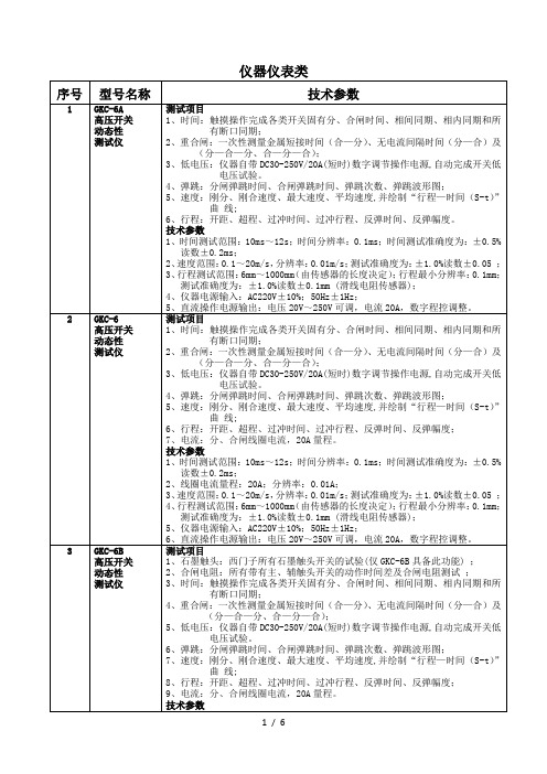
交流阻抗测试仪
测试项目
1、电流;
2、电压;
3、阻抗;
4、功耗;
主要技术参数
1、电流测量范围:100mA~50A;
2、电流测量准确度:±0.5%读数±1mA;
3、电压测量范围:5V~500V;
4、电压测量准确度:±0.5%读数±0.01V;
5、采样率: 2000点/周波(电压、电流各1000点);
4、行程测试范围:6mm~1000mm(由传感器的长度决定);行程最小分辨率:0.1mm;测试准确度为:±1.0%读数±0.1mm(滑线电阻传感器);
5、仪器电源输入:AC220V±10%;50Hz±1Hz;
6、直流操作电源输出:电压20V~250V可调,电流20A,数字程控调整。
3
GKC-6B
高压开关
5、直流操作电源输出:电压20V~250V可调,电流20A,数字程控调整。
2
GKC-6
高压开关
动态性
测试仪
测试项目
1、时间:触摸操作完成各类开关固有分、合闸时间、相间同期、相内同期和所有断口同期;
3、2、重合闸:一次性测量金属短接时间(合—分)、无电流间隔时间(分—合)及
(分—合—分、合—分—合);
2、特征数据、波形同屏显示。
3、多种电压基准信号取样方式:
(1)有线方式:从PT端计量绕组取信号,数字信号有线传输。
(2)无线方式:从PT端计量绕组取信号,数字信号无线传输,省去电缆长距离连接。
(3)无电压方式:不需要从PT端子取信号,采用软件计算的方式找到电压基准。
技术指标
1、仪器电源输入:220V、50Hz或内部电源。
电流:全电流>100μA时: ±5%读数±1个字;
KDS晶振型号对照及最小包装

DSA开头的晶振型号是压控温补振荡器DSB开头的晶振型号是温补振荡器DSO开头的晶振型号是普通振荡器DSX,DST开头的晶振型号是无源晶振DSV开头的晶振型号压控振荡器DSF开头的是KDS晶体滤波器型号对照表:大真空精工爱普生西铁城瑞士微晶Size(mm)KDS Seiko EPSON Citizen Microcrystal3.0*8.0DT-38C-001R2.0*6.0DT-26VT-200-F C-002RX CFS-206DS261.5*5.0DT-14VT-150-F C-004R CFS-145DS151.2*4.6VT-120-F C-005R DS108.0*3.8DMX-26S SPA-T2-F MC-306CM200C CC1V-T1A(2pin)7.0*1.5SSP-T7-F MC-146MS2V-T1R5.05*1.8SM-14J MS2V-T3R6.0*2.5DST6214.8*1.9DST520FC-255CM519CC4V-T1A4.1*1.5DST410S FC-145CM415CC5V-T1A3.2*1.5DST310S FC-135CM315CC7V-T1A2.0*1.2FC-12M CM212CX8V-T1A 32.768K系列型号(KDS)型号频率范围尺寸封装、包装详细属性DT-2632.768KHZΦ2.0×6.0袋装/2K33无源晶振DT-26128to100kHzΦ2.0×6.0袋装/2K33无源晶振DT-3832.768kHzΦ3.0×8.0袋装/2K33无源晶振DT-38114.75to153.6kHzΦ3.0×8.0袋装/2K33无源晶振DST210A32.768kHz 2.0×1.2×0.5盘装/3K26无源晶振DST310S32.768KHZ 3.2×1.5×0.75盘装/3K27无源晶振DST410S32.768kHz 4.1×1.5×0.75盘装/3K27无源晶振DST52032.768kHz(30to100kHz) 4.8×1.9×0.8盘装/3K28无源晶振DST62132.768kHz(30to100kHz 6.0×2.5×1.0盘装/3K28无源晶振SM-26F32.768kHz(30to100kHz) 1.9×6.0×3.25盘装/2.5K29无源晶振DMX-26S32.768kHz(30to100kHz)8.0×3.8×2.4盘装/2.5K30无源晶振DMX-2632.768kHz(30to100kHz)9.2×3.4×3.0盘装/2.5K30无源晶振DMX-3832.768k(14.75to100kHz)13.2×4.9×4.5盘装/1K30无源晶振MHZ系列型号(KDS)型号频率范围尺寸封装、包装属性附加金属面DSX1612A32to52MHz 1.6×1.2×0.3盘装/3K无源11DSX211G20to54MHz 2.0×1.6×0.65盘装/3K无源陶瓷面16 DSX211A24to50MHz 2.0×1.6×0.45盘装/3K无源金属面11 DSX211AL26to50MHz 2.0×1.6×035盘装/3K无源金属面11 DSX211SH24to50MHz 2.05×1.65×0.45盘装/3K无源金属面15 DSX221G12to62.4MHz 2.5×2.0×0.75盘装/3K无源陶瓷面17 DSX221S12to60MHz 2.5×2.0×0.5盘装/3K无源金属面12 DSX221SH16to54MHz 2.5×2.0×0.45盘装/3K无源金属面15 DSX321G8to64MHz 3.2×2.5×0.75盘装/3K无源陶瓷面18 DSX321SL13to60MHz 3.2×2.5×0.5盘装/3K无源金属面13 DSX321SH12to50MHz 3.2×2.5×0.65盘装/3K无源金属面15 DSX530GA7to70MHz 5.0×3.2×1.0盘装/1K无源2脚陶瓷19 DSX531S10to70MHz 4.9×3.1×0.75盘装/1K无源4脚金属14 DSX630G8to80MHz 6.0×3.5×1.2盘装/1K无源2脚陶瓷20 DSX840GA8to80MHz8.0×4.5×1.4盘装/1K无源2脚陶瓷20 DSX840GT4to8MHz8.0×4.5×1.8盘装/1K无源2脚陶瓷21 DSX151GAL 3.5to55MHz11.8×5.5×2.5盘装/1K无源4脚陶瓷22SMD-49 3.072to70MHz11.0×4.6×4.2盘装/1K无源23 DMX-38 3.579to28MHz13.2×4.9×4.5盘装/1K无源24 AT-49 3.072to70MHz11.0×4.6×3.3袋装/1K无源31压控温补振荡器型号型号频率尺寸封装、包装属性DSA211SCL(VC-TCXO)13to52MHz 2.1×1.7×0.63盘装/2K VC-TCXO46 DSA211SDA(VC-TCXO)13to52MHz 2.1×1.7×0.63盘装/2K VC-TCXO48 DSA211SDT(VC-TCXO)13to52MHz 2.1×1.7×0.66盘装/2K VC-TCXO43 DSA222MAA(VC-TCXO Module)13to52MHz 2.5×2.0×0.7盘装/2K VC-TCXO44 DSA222MAB(VC-TCXO Module)13to40MHz 2.5×2.0×0.7盘装/2K VC-TCXO44 DSA221SCL(VC-TCXO)9.6to52MHz 2.5×2.0×0.8盘装/2K VC-TCXO46 DSA221SDA(VC-TCXO)9.6to52MHz 2.5×2.0×0.8盘装/2K VC-TCXO48 DSA221SDT(VC-TCXO)9.6to52MHz 2.5×2.0×0.8盘装/2K VC-TCXO43 DSA221SJ(VC-TCXO)10to40MHz 2.5×2.0×0.8盘装/2K VC-TCXO51 DSA321SCL(VC-TCXO)9.6to52MHz 3.2×2.5×0.9盘装/2K VC-TCXO46 DSA321SDA(VC-TCXO)9.6to52MHz 3.2×2.5×0.9盘装/2K VC-TCXO48 DSA535SC(VC-TCXO)10to30MHz 5.0×3.2×1.35盘装/4K VC-TCXO46 DSA535SD(VC-TCXO)9.6to40MHz 5.0×3.2×1.05盘装/4K VC-TCXO48 DSA535SG(VC-TCXO)10to40MHz 5.0×3.2×1.35盘装/1K VC-TCXO50温补振荡器型号型号频率范围尺寸封装、包装属性DSB211SCL(TCXO)13to52MHz 2.1×1.7×0.63盘装/2K TCXO46 DSB211SCB(TCXO)13to52MHz 2.1×1.7×0.63盘装/2K TCXO46 DSB211SDA(TCXO)13to52MHz 2.1×1.7×0.63盘装/2K TCXO48 DSB211SDB(TCXO)13to52MHz 2.1×1.7×0.63盘装/2K TCXO48 DSB211SDT(TCXO)13to52MHz 2.1×1.7×0.66盘装/2K TCXO43 DSB222MAA(TCXO)13to52MHz 2.5×2.0×0.7盘装/2K TCXO44 DSB222MAB(TCXO)13to40MHz 2.5×2.0×0.7盘装/2K TCXO44 DSB221SCL(TCXO)9.6to52MHz 2.5×2.0×0.8盘装/2K TCXO46 DSB221SCB(TCXO)9.6to52MHz 2.5×2.0×0.8盘装/2K TCXO46 DSB221SDA(TCXO)9.6to52MHz 2.5×2.0×0.8盘装/2K TCXO48 DSB221SDB9.6to52MHz 2.5×2.0×0.盘装/2K TCXO48 DSB221SDT(TCXO)9.6to52MHz 2.5×2.0×0.8盘装/2K TCXO43 DSB221SJ(TCXO)10to40MHz 2.5×2.0×0.盘装/2K TCXO51 DSB321SCL(TCXO)9.6to52MHz 3.2×2.5×0.9盘装/2K TCXO46 DSB321SCB9.6to52MHz 3.2×2.5×0.9盘装/2K TCXO46 DSB321SDA(TCXO)9.6to52MHz 3.2×2.5×0.9盘装/2K TCXO48 DSB321SDB9.6to52MHz 3.2×2.5×0.9盘装/2K TCXO48 DSB535SC(TCXO)10to30MHz 5.0×3.2×1.35盘装/4K TCXO46 DSB535SD(TCXO)9.6to40MHz 5.0×3.2×1.05盘装/4K TCXO48 DSB535SG(TCXO)10to40MHz 5.0×3.2×1.35盘装/4K TCXO50压控振荡器型号TH021TH87153998型号频率范围尺寸封装、包装属性DSV211AR19.2to30MHz,38.4to60MHz 2.0×1.6×0.72盘装/2K VCXO66 DSV211AV12MHz,19.2to80MHz 2.0×1.6×0.72盘装/2K VCXO66 DSV221SR7.5to60MHz 2.5×2.0×0.815盘装/2K VCXO67 DSV221SV 6.75to90MHz 2.5×2.0×0.815盘装/2K VCXO67 DSV321SR13.5to54MHz 3.2×2.5×1.1盘装/2K VCXO68 DSV321SV 6.75to90MHz 3.2×2.5×1.1盘装/2K VCXO68 DSV323SD80to170MHz 3.2×2.5×1.1盘装/2K VCXO70 DSV323SJ80to170MHz 3.2×2.5×1.1盘装/2K VCXO70 DSV323SK40to170MHz 3.2×2.5×1.1盘装/2K VCXO70 DSV323SV 6.75to186MHz 3.2×2.5×1.1盘装/2K VCXO70 DSV531SB5to50MHz 5.0×3.2×1.2盘装/1K VCXO69 DSV531SV 1.25to80MHz 5.0×3.2×1.2盘装/1K VCXO69 DSV532SB5to50MHz 5.0×3.2×1.1盘装/1K VCXO69 DSV532SV 1.25to80MHz 5.0×3.2×1.1盘装/1K VCXO69DSV753HJ170to350MHz7.0×5.0×2.0盘装0.1/0.5VCXO72DSV753HK170to350MHz7.0×5.0×2.0盘装0.1/0.5VCXO72DSV753SB4to50MHz7.0×5.0×2.0盘装/2K VCXO71 DSV753SD80to170MHz7.3×4.9×1.5盘装/2K VCXO71 DSV753SJ80to170MHz7.3×4.9×1.5盘装/2K VCXO71 DSV753SK40to170MHz7.3×4.9×1.5盘装/2K VCXO71 DSV753SV2to170MHz7.3×4.9×1.5盘装/2K VCXO71石英振荡器型号型号频率范围尺寸封装、包装属性DSO1612AR0.584375to80MHz 1.6×1.2×0.5盘装/2K SPXO55 DSO211AB 3.25to52MHz 2.0×1.6×0.72盘装/2K SPXO61 DSO211AH 1.2to80MHz 2.0×1.6×0.72盘装/2K SPXO54 DSO211AN9.6to80MHz 2.0×1.6×0.72盘装/2K SPXO60 DSO211AR0.4to80MHz 2.0×1.6×0.72盘装/2K SPXO56 DSO213AW 3.25to60MHz 2.0×1.6×0.53盘装/2K SPXO53 DSO221SBM 3.25to52MHz 2.5×2.0×0.815盘装/2K SPXO61 DSO221SH 3.5to52MHz 2.5×2.0×0.815盘装/2K SPXO54 DSO221SN 1.5625to100MHz 2.5×2.0×0.815盘装/2K SPXO60 DSO221SR0.2to167MHz 2.5×2.0×0.815盘装/2K SPXO58DSO221SW3to60MHz 2.5×2.0×0.8盘装/2K SPXO53 DSO321SBM0.7to90MHz 3.2×2.5×1.1盘装/2K SPXO61 DSO321SBN0.7to90MHz 3.2×2.5×1.1盘装/2K SPXO61 DSO321SVN0.7to90MHz 3.2×2.5×1.1盘装/2K SPXO61 DSO321SH 3.5to52MHz 3.2×2.5×1.1盘装/2K SPXO54 DSO321SN 1.5625to100MHz 3.2×2.5×1.1盘装/2K SPXO60 DSO321SR32.768to50kHz 3.2×2.5×1.1盘装/2K SPXO57/58 DSO321SW3to60MHz 3.2×2.5×0.9盘装/2K SPXO53 DSO323SD13.5to212.5MHz 3.2×2.5×1.1盘装/2K SPXO62 DSO323SJ13.5to212.5MHz 3.2×2.5×1.1盘装/2K SPXO62 DSO323SK13.5to212.5MHz 3.2×2.5×1.1盘装/2K SPXO62 DSO531SBM0.7to90MHz 5.0×3.2×1.1盘装/1K SPXO61 DSO531SBN0.7to90MHz 5.0×3.2×1.1盘装/1K SPXO61 DSO531SVN0.7to90MHz 5.0×3.2×1.1盘装/1K SPXO61 DSO531SR0.2to167MHz 5.0×3.2×1.1盘装/1K SPXO58 DSO533SJ13.5to212.5MHz 5.0×3.2×1.1盘装/1K SPXO63 DSO533SK13.5to212.5MHz 5.0×3.2×1.1盘装/1K SPXO63 DSO751SBM0.7to90MHz7.3×4.9×1.5盘装/1K SPXO61 DSO751SBN0.7to90MHz7.3×4.9×1.5盘装/1K SPXO61 DSO751SR0.2to167MHz7.3×4.9×1.5盘装/1K SPXO58DSO753HJ212.5to350MHz7.0×5.0×2.0盘装0.1/0.5SPXO65DSO753HK212.5to350MHz7.0×5.0×2.0盘装0.1/0.5SPXO65DSO753HV170to230MHz7.0×5.0×2.0盘装0.1/0.5SPXO65DSO753SD13.5to212.5MHz7.3×4.9×1.5盘装/1K SPXO64 DSO753S J13.5to212.5MHz7.3×4.9×1.5盘装/1K SPXO64 DSO753SK13.5to212.5MHz7.3×4.9×1.5盘装/1K SPXO64。
施耐德Easy Altivar ATV610 变频器编程手册 说明书
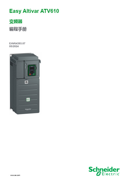
[简单起动] SYS– .......................................................................................32 [Macro-configuration] CFG- 菜单........................................................33 [简单起动] SIM- 菜单...........................................................................34 [修改的参数] LMD- 菜单 .......................................................................38
Easy Altivar ATV610
变频器 编程手册
EAV64393.07 05/2024
法律声明
本文档中提供的信息包含与产品/解决方案相关的一般说明、技术特性和/或建议。
本文档不应替代详细调研、或运营及场所特定的开发或平面示意图。它不用于判定产 品/解决方案对于特定用户应用的适用性或可靠性。任何此类用户都有责任就相关特定 应用场合或使用方面,对产品/解决方案执行或者由所选择的任何业内专家(集成师、 规格指定者等)对产品/解决方案执行适当且全面的风险分析、评估和测试。
对于将本文档 或其内容用作商业用途的行为,施耐德电气未授予任何权利或许可,但 以“原样”为基础进行咨询的非独占个人许可除外。
监控景阳摄像机全系列
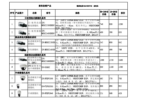
1/3 ″ SONY CCD , 水 平 分 辨 率 450 线 3Lux/F1.2;NEXTCHIP DSP;DC12V输入
,
0.
480
490
766
超级宽动态摄像机系列
5
高清晰度日夜 型宽动态摄像 SN机(DPS) BXC5860DDN
1/3″DPS,水平分辨率540线,垂直分辨率460 线 ; 彩 转 黑 功 能 ( 带 可 移 除红 外滤 光片 ), 1360 0.5Lux/F1.2(0Lux,配红外灯);中英文双语言
195
308
300(L)*80(W)*76(H)mm;IP66;输入电压
28
室内 护罩
/
室
外
防
SN-CH304HF
铝合金材质;外形尺 410(L)*120(W)*108(H)mm; 内 部 尺 300(L)*80(W)*76(H)mm;IP66;输入电压
寸 寸 295
345
490
支架
29
摄像机支架
SN-BK312B
SN-IRC5830/M
1/3″SONY SUPER HAD CCD,水平分辨率540 线,夜视距离40—50米;0Lux,红外灯开启; NEXTCHIP DSP ; CS 接 口 IR 定 焦 镜 头 ( 12 ,
590
640
1000
12
高清红外防水 型一体化摄像 机
SN-IRC4840/M
116/3m″mS)O;NYDCCC12DV,输水入平分辨率420线,夜视距离 40 — 50 米 ; 0Lux , 红 外 灯 开 启 ; NEXTCHIP DSP ; CS 接 口 IR 定 焦 镜 头 ( 12 , 16mm ) ; DC12V输入
红外报警主机说明书.

CVC064-C用户使用手册神州太讯安防总线报警系统说明CVC064-C通讯主机系统是具有很强的使用性被广泛地应用在小区住家及周界报警系统大楼安保系统、以及工厂学校仓储等各类大型安保系统可实现计算机管理并方便地与其它系统集成。
CVC064-C主要功能及性能指标一. 主要功能●最多可接520个防区:自身带有8个有线,通过通讯接口可以外接最多64个报警模块或者可独立布撤防的8防区小主机,每个输入设备最多可接8个防区●整个主机可以分为8个子系统,每个子系统相当于一台主机。
●外接的接警设备(报警模块或小主机)从000设备开始,按照地址码的顺序,最大64个设备,地址码是63,64号设备是主板自身8个防区。
每个键盘可以拥有其中的1个或多个设备,各键盘分别对自己的所管辖的所有设备同时进行布防、撤防等操作;键盘可以对单个设备、防区独立进行布防、撤防操作●可最多接入8个键盘,独立操作,汉字界面。
其中1个主键盘、7个从键盘,通过主键盘或管理密码编程可以让任意键盘跟随所有报警并显示报警信息●挂在通讯总线上的设备都可以带有1-32个输出,其中报警模块最多带有1个输出,32路指示灯最多可带4块指示灯板128路输出。
每个防区可以联动最多3个输出,联动包括:防区报警联动、防区布撤防联动、防区异常联动。
可以达到电子地图、DVR 报警输入、就地报警等功能●有3个密码权限,包括管理、编程、操作●可实现与中心计算机连接●可通过电话线与报警中心通过Contact ID协议连接,并可电话通知用户●通过键盘密码、遥控器、中心计算机、电话进行撤/布防●通过管理密码或者对主键盘(0号键盘)的撤布防,同时对所有键盘进行撤布防●通过键盘对单个分区、防区进行布撤防●通过键盘对联动设备单个或全部进行操作●通过电脑进行编程和配置。
可远程配置好,文件发送,就地写入主机,让编程和服务更为简单、有效。
二.电性能指标●输入电源AC16.5V●主机板耗电静态300mA●报警状态850mA●输出电源DC13.8V●报警输出口DC14V 800mA●外观尺寸350 x 280 x 75mm●键盘端口总线总长度不得大于1200m●通讯端口总线总长度每个接口不得大于1200m,两个接口最多可达2400m第一章. 系统配置及连线说明一. 主板接线端口定义及系统基本配置CVC064-C 通讯主机是一种大型的报警系统,它本身留有8个有线防区输入接口。
威视达 视频监控产品表

超级高清晰宽动态枪型摄像机 VCC-600P产品简介为了满足广大客户逐步增长的安防监控需求,霍尼韦尔隆重推出威视达VCC-600枪型摄像机。
VCC-600 采用了1/3” Sony HAD CCD ,在彩色模式中,可以实现超过540线高清晰的分辨率。
优越的电子降噪功能和日夜转换功能使该系列摄像机可以在多种复杂的环境中满足客户更高级的安防监控需求。
同时该款摄像机还拥有强大的宽动态、强光抑制、动态侦测、隐私区遮挡和数字放大等功能,成为支持客户进行更加灵活和有效的安防监控不可或缺的系列产品。
采用霍尼韦尔独有的BMB强光抑制技术, VCC-600P可以自动监测和抑制环境中的强光,这项功能特别适用夜间监视停车场和快速通道。
搭配应用于不同环境的护罩,VCC-600系列摄像机可以广泛地应用在室内和室外等各种监控场所。
该设备的安装和调试方便快捷,并配有多种语言的控制菜单。
特点∙1/3" Sony Super HAD CCD∙大于540TV 线的水平分辨率∙日夜转换∙强光抑制(BMB), 背光补偿(BLC), 宽动态(WDR), 超级电子降噪(DNR)∙隐私区遮挡、动态侦测、数字放大技术参数红外柱型外调焦摄像机 VBC-800P产品简介霍尼韦尔威视达系列VBC-800PI红外柱型外调焦摄像机专为商业和居住环境设计,是室外监控的理想选择。
它具有540线超强分辨率和良好的图像效果。
红外可视距离可达25米,采用防眩光反光双玻璃镜片和红外智能技术。
VBC-800PI摄像机采用红外技术,即使在完全漆黑的环境,依然能达到很好的可视效果。
VBC-800PI出厂时已完成组装,用户只需将摄像机通过摄像机自带的墙壁安装支架固定在墙壁,安装方便快捷。
VBC-800PI为您提供良好的监控服务,能全面捕获监控范围内的所有活动,保护您的财产安全,值得信赖。
此外,VBC-800PI集摄像机、防护罩、镜头、红外灯于一体,自动感应红外功能,真正的24小时全天候监控,室内外通用。
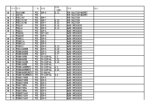
FSC型号
DIP-7 DIP-8 7-MLSOP DIP-8 SOP-8 DIP-8 SOP-8 DIP-8 SOP-8 DIP-8 SOP-8 DIP-8 SOP-8 TO-220F-5L TO-220F-5L TO-220F-5L TO-220F-5L TO-220F-5L TO-220F-5L TO-3PL-7L DIP-8 SOP-8 DIP-8 SOP-8 SOP-8 DIP-8
备注
★ ★ ★ ★ ★ ★ ★ ★ ★ ★ ★ ★ ★ ★ ★ ★ ★ ★ ★ ★ ★ ★ ★ ★ ★ ★ 7 48 49 50 51 52 53 54 55 56 57 58 59 60 61 62 63 64 65 66 67 68 69 70 71 72 73 74 75 76 77
FSC FSC FSC FSC FSC FSC FSC FSC FSC FSC FSC FSC FSC FSC FSC FSC FSC FSC FSC FSC FSC FSC FSC FSC FSC FSC FSC FSC FSC FSC FSC FSC FSC FSC FSC FSC
DIP-8 DIP-8 DIP-8 DIP-8 DIP-8 DIP-8 DIP-8
FAN7530M FAN7530MX FAN7930M FAN7930MX FAN7930BM FAN7930BMX FAN7930CM FAN7930CMX FAN6961SZ FAN6961DZ FAN6961SY FAN6921MLMY FSFR2100U FSFR2100 FSFR2000 FSFR1900 FSFR1800 FSFR1700 FSFR1600 FSFR1600L FSFR1700L FSFR1800L FSFR2100US FSFR1800US FSFR1700US FSFR2100USL FSFR1800USL FSFR1700USL FSFR2100XS FSFR1800XS FSFR1700XS FSFR1600XS FSFR2100XSL FSFR1800XSL FSFR1700XSL FSFR1600XSL
车间监控安装结算表
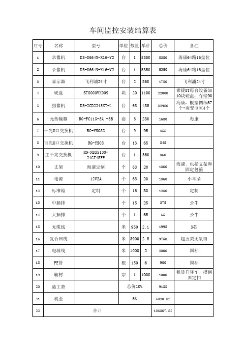
电源
RG-YS08 RG-NBS5100-
24GT4SFP 海康定制
12V2A
台 13 65
845
台 1 360 360
个 68 20
1360
海康,包括支架和 固定包箍
个 68 20 1360
小耳朵
12
标准箱
定制
个 16 80 1280定制13源自中插排个 15 25
375
公牛
14
大插排
个 1 65
65
公牛
15
光缆线
米 950 2.1 1995
8芯
16 复合网线
米 3900 2.5 9750
超五类无氧铜
17
电源线
米 1000 2
2000
国标
18
PE管
19
辅材
20
施工费
根 150 6
900
国标
宗 1 1000
1000
租赁升降车、槽钢 固定扣
总价10%
9122
21
税金
6%
6020.82
22
合计
106367.82
车间监控安装结算表
序号
名称
型号
单位 数量 单价 总价
备注
1
录像机
DS-8664N-K16-V2 台 1 5350 5350 海康64路16盘位
2
录像机
DS-8664N-K16-V2 台 1 5350 5350 海康64路16盘位
3
显示器
4
硬盘
5
摄像机
6 光传输器
飞利浦24寸 ST8000VX009 DS-2CD2245XT-L RG-FC11G-3A -3B
- 1、下载文档前请自行甄别文档内容的完整性,平台不提供额外的编辑、内容补充、找答案等附加服务。
- 2、"仅部分预览"的文档,不可在线预览部分如存在完整性等问题,可反馈申请退款(可完整预览的文档不适用该条件!)。
- 3、如文档侵犯您的权益,请联系客服反馈,我们会尽快为您处理(人工客服工作时间:9:00-18:30)。
M3-05-S010(0)2005.05.19 GREVISION RECORD REVISION INDEX 12345678910111213141516171819202122232425260INITIAL RELEASEALLPAGEREV. NO.REV. DATE REV. NO.2005. 05. 19,REMARKDESCRIPTION OF REVISIONPAGE 2005.05.1902 OF 26Contents1. Features ......................(4)2. Mechanical Data......................(4)3. Absolute Maximum Ratings ......................(5)4. Electrical Characteristics ......................(6)5. Electro-optical Characteristics ......................(7)6. Circuit Block Diagram ......................(8)7. Application Circuit ......................(8)8. Instruction Description ......................(9)9. DDRAM Address ......................(14)10. Initialization Example ......................(15)11. Pin Connections ......................(16)12. AC Characteristics ......................(17)13. Reliability......................(19)14. Quality Specifications ......................(20)15. Outline Dimension ......................(22)16. Packing......................(23)17. Marking & Others ......................(24)18. General Precautions......................(25),2005.05.1903 OF 261. FeaturesDisplay Format : 96(W) x B.G.R. x 64(H) dots Display Color : 65K colorsDriver Element : passive matrix OLED(Organic Light Emitting Diode)Interface : 8bit parallel data with MPU(8080-series MPU)Multiplexing Ratio : 1/64 DutyControl IC / Drive IC : SSD1332 (Manufacturer : Solomon systech, Inc)Polarizer : Anti-glare Pol.Applications : Display terminal for mobile phone, MP3 player 2. Mechanical Data(1)Refer to the Outline Dimension at the page 22Note (1) : COF unfolded,ItemOutline Dimension Number of dots Viewing area Active area 2005.05.1904 OF 26Pixel pitch Dot pitch Dot size WeightGlass thicknessUnit Specificationmm mm mm mm g mm27.8(W) x 37.24(H) x 1.73(T,Max.)Notemm dot mm 96(W) x(B.G.R) x 64(H)24.8(W) x 19.8(H)21.0(W) x 16.038(H)0.7 ±0.070.219(W) x 0.251(H)0.073(W) x 0.251(H)0.049(W) x 0.225(H)3 Max.3. Absolute Maximum Ratings(Ta=23±5℃, Vss=GND=0)(2) (2)(3)Note (2) : Voltage relationship VCC > VDD > VSS must always be satisfied.Note (3) : Wet bulb temperature should be 29℃ max. and no condensation of water.,-0.3VDD -0.3 4.018ItemSupply VolatgeLogic OLEDMax.Min.Symbol VCC NoteUnit V V V ℃℃%RHVIN TOPT TSTG -Input Voltage Operating Temp.Storage Temp.Humidity-0.3-20-30-VDD+0.36080902005.05.1905 OF 264. Electrical Characteristics(Ta=23±5℃, Vss=GND=0)(4) (6) (5) (6)Note (4) : VDD=2.8[V], VCC=13[V]Gray Scale=01h,02h,03h,04h,06h,08h,0Ah,0Ch,0Eh,10h,12h,14h,17h,1Ah,1Dh,20h24h,28h,2Ch,30h,35h,3Ah,3Fh,44h,4Ah,50h,56h,5Ch,63h,6Ch,76h,7DhNote (5) : VDD=2.8[V], VCC=15[V]Gray Scale=01h,02h,03h,04h,06h,08h,0Ah,0Ch,0Eh,10h,12h,14h,17h,1Ah,1Dh,20h24h,28h,2Ch,30h,35h,3Ah,3Fh,44h,4Ah,50h,56h,5Ch,63h,6Ch,76h,7DhNote (6) : 100% White Pattern2005.05.19,26 OF 26SET CONTRAST FOR COLOR ( A, B, C) =(21h,12h,2Fh), MASTER CURRENT CONTROL=0Fh,PRECHARGE (A, B, C)=(3Ch,3Fh,3Fh), AJ-PER=00h,01h ,VCOMH=3FhItemVDD VCC VIH Supply Volatge Input Voltage Logic OLED High Low NoteUnit V ICCIDD Symbol VIL mA mA mAV V V Max.3.5015.00VDD 0.2VDD Typ.Min.0.8VDD VSS -2.407.00 2.8013.00--Current ConsumptionLogic OLED---0.25PRECHARGE (A, B, C)=(23h,37h,2Dh), AJ-PER=00h,01h ,VCOMH=23hSET CONTRAST FOR COLOR ( A, B, C) =(1Dh,10h,20h), MASTER CURRENT CONTROL=0Fh,--6.199.545. Electro-optical Characteristics(Ta=23±5℃, Vss=GND=0)(8) (9) (11)(7) (9) (10) (11) (8) (9) (10) (11)Note (7) : VDD=2.8[V], VCC=13[V]Gray Scale=01h,02h,03h,04h,06h,08h,0Ah,0Ch,0Eh,10h,12h,14h,17h,1Ah,1Dh,20h24h,28h,2Ch,30h,35h,3Ah,3Fh,44h,4Ah,50h,56h,5Ch,63h,6Ch,76h,7DhNote (8) : VDD=2.8[V], VCC=15[V]Gray Scale=01h,02h,03h,04h,06h,08h,0Ah,0Ch,0Eh,10h,12h,14h,17h,1Ah,1Dh,20h24h,28h,2Ch,30h,35h,3Ah,3Fh,44h,4Ah,50h,56h,5Ch,63h,6Ch,76h,7DhNote (9) : 100% White PatternNote (10) : Half value of initial luminance.Note (11) : Measurement System Measuring Instrument : SR-3 Environment : Inside a darkroom--LFw(1)LFw(2)7,000--% (7) (9) (11) (7) (9) (11)Area in CIE diagram (7) (9) (11) (7) (9) (11)0.2020.2520.152610.1560.2060.2820.3320.6230.6600.71065-0.6730.3730.4230.3070.2740.3240.3570.407Life TimeColor Chromaticity (CIE1931)Red Green Blue0.106White(1)White(2)CIERx CIERy 0.5730.3230.2320.6102,200Hr HrNote(7) (9) (11) (7) (9) (11) (7) (9) (11) (7) (9) (11) (7) (9) (11) (7) (9) (11)Unit CIEGy CIEBx CIEBy CIEWx CIEWy CIEGx ㏅/㎡㏅/㎡Lw(1)Lw(2)25450.22440-LuminanceWhite White(1)White(2),ItemMax.Typ.Min.Symbol SET CONTRAST FOR COLOR ( A, B, C) =(1Dh,10h,20h), MASTER CURRENT CONTROL=0Fh,PRECHARGE (A, B, C)=(23h,37h,2Dh), AJ-PER=00h,01h ,VCOMH=23hSET CONTRAST FOR COLOR ( A, B, C) =(21h,12h,2Fh), MASTER CURRENT CONTROL=0Fh,PRECHARGE (A, B, C)=(3Ch,3Fh,3Fh), AJ-PER=00h,01h ,VCOMH=3Fh2005.05.197 OF 266. Circuit Block Diagram7. Application Circuit,8 OF 262005.05.19C82.2uF U1SSD1332U1R1 COF8. Instruction Desciption (Refer to the data sheet of SSD1332),2005.05.199 OF 262005.05.1910 OF 26M3-05-S010(0) 2005.05.19 0 11 OF 26M3-05-S010(0) 2005.05.19 0 12 OF 26M3-05-S010(0) 2005.05.19 0 13 OF 26M3-05-S010(0) 2005.05.19 0 14 OF 26 9. DDRAM AddressM3-05-S010(0) 2005.05.19 0 15 OF 26 10. Initialization ExampleVDD=2.8[V], VCC=13[V]M3-05-S010(0) 2005.05.19 0 16 OF 26 11. Pin ConnectionsPin No Symbol NC 1 VCC 2 VCOMH 3 NC 4 D7 5 D6 6 D5 7 D4 8 9 D3 10 D2 11 D1 12 D0 13 E(RD) 14 RW#(WR) 15 DC# 16 RES# 17 CS# 18 IREF 19 BS2 20 BS1 21 VDD 22 VP-C 23 VP-B 24 VP-A VBREF 25 26 27 28 29 30 31 RESE FB VDDB GDR VSS NC I/O P I I/O I/O I/O I/O I/O I/O I/O I/O I I I I I O I I P I/O I/O I/O I I I P O P Descirption No Connection The Most Positive voltage The voltage output high level for COM signals No Connection 8-bit bi-direction data bus 8-bit bi-direction data bus 8-bit bi-direction data bus 8-bit bi-direction data bus 8-bit bi-direction data bus 8-bit bi-direction data bus 8-bit bi-direction data bus 8-bit bi-direction data bus Read enable pin("Low" enable). Write enable pin("Los" enable). Address input pin.("Low"=Command, "High"=Parameter) Reset input pin When RSTB is "Low", Initialization is executed. Chip select input pin("Low" enable). The segment output current reference pin. These pins are used to configure MCU interface selection These pins are used to configure MCU interface selection Logic Power supply The pre-charge driving voltages for OLED driving segment pins The pre-charge driving voltages for OLED driving segment pins The pre-charge driving voltages for OLED driving segment pins The internal voltage reference of booster circuit. Connects to the source current pin of the external NMOS of the booster circuit. The feedback resistor input of the booster circuit.The power supply for the internal buffer of the DC-DC voltage converter.RemarkDrive the gate of the external NMOS Ground No ConnectionM3-05-S010(0) 2005.05.19 0 17 OF 26 12. AC Characteristics 12-1. 6800-series MPU parallel interfaceM3-05-S010(0) 2005.05.19 0 18 OF 26 12-2. 8080-series MPU parallel interfaceM3-05-S010(0) 2005.05.19 0 19 OF 26 13. Reliability 13-1 Test Items and Conditions Item High Temp. Operation Low Temp. Operation High Temp. Storage Low Temp. Storage High Temp. & High Humi. Storage Temperature Cycle Thermal Shock Test Condition 60 ± 2℃, 96hrs -20 ± 2℃, 96hrs 80 ± 2℃, 96hrs -30 ± 2℃, 96hrs 60 ± 2℃,90 ± 2%RH, 96hrs 25℃(0.5h) → -20℃(3h)→ 25℃(1h) → 60℃(3h)→ 25℃(0.5h), 10cycles 25℃(5m) → -30℃(30m) → 25℃(5m) → 80℃(30m), 20cycles Frequency = 10~55Hz Mechanical Amplitude : 2mm Sweep : 1min(sine curve) Each 20 min for X/Y/Z Note(12) After the above reliability test, the samples should be left under room temperature for 2 hours and then should be inspected for normal operation. Note(13) The conditions for driving at operation tests shall be the same as indicated on the above description except for the temperature and humidity conditions. 3 box Criteria for Pass/Fail (12) (13) (12) (13) (12) (12) (12) (12) (12)13-2 Criteria for Reliability Test (1) There shall be no abnormality in the functions and the display. (2) No irregularities shall be found for the appearance and structure. (3) The luminance change should be within 50% of initial value(based on white).M3-05-S010(0) 2005.05.19 0 20 OF 26 14. Quality Specifications 14-1 Acceptance Quality Level(AQL) Inspection Item Major Sampling Procedures KS A 3109 Inspection level II normal inspection Single sampling plan KS A 3109 Inspection level II Minor (1) Major defect : Defect which influence display function or reliability issues. (2) Minor defect : Defects which satisfy all functions, but no impact to reliability issues. normal inspection Single sampling plan 1.5 0.65 AQL14-2 Inspection Conditions The environmental conditions for inspection shall be as follows, - Room Temperature : 25±3℃ - Humidity : 60±20%RH - Brightness : 300~500 [lux]14-3 Definition of the Area14-4 Inspection Standards1) No display5) Cross line defects 2) Abnormal Operation 6) Short Circuit 3) Vertical Line defects 7) Pattern Open4) Horizontal line defectsSize Φ(mm)Acceptable number Φ≤ 0.15Ignore 0.15<Φ≤0.2540.25<Φ≤0.302Φ>0.300Size Φ(mm)Acceptable number Φ≤ 0.10Ignore 0.10<Φ≤0.151Φ>0.150Size Φ(mm)Acceptable number Φ≤ 0.20Ignore 0.20<Φ≤0.5030.50<Φ≤0.802Φ>0.800Size (mm)Acceptable number L≤0.15,W≤0.153L>0.15,W>0.150Size (mm)Acceptable number Φ≤0.23Φ>0.2Pin holesMajor MinorMinor Minor Minor Minor Bright/DarkspotGlassContaminationPolarizer bubbleDentsCriteria of defectsDefect typeItemsDisplay on inspection,2005.05.19021 OF 2617. Marking & Others※Label(138x95mm) description ⓐ : Product name ⓑ : Manufacture date ⓒ : Serial number of box ⓓ : Quantity ⓔ : Unit ⓕ : Customerⓖ : Inspector signature,2005.05.19024 OF 2618. General Precautions18-1 Handling(1) When the module is assembled, it should be attached to the system firmly.Be careful not to twist and bend the module.(2) Refrain from strong mechanical shock and / or any force to the module. Do nottwist and bend because it may cause improper operation or damage to the module.(3) Note that polarizers are very fragile and can be easily damaged. Do not pressor scratch the surface more than a B pencil lead.(4) Wipe off water droplets or oil immediately. If you leave the droplets for a long time,staining and discoloration may occur.(5) If the surface of the polarizer is dirty, clean it with some absorbent cotton orsoft cloth.(6) The desirable cleaner is water, IPA(Isopropyl Alcohol) or Hexane.Do not use Ketone type materials(ex, Acetone), Ethyl alcohol, Toluene, Ethyl acid or Methyl chloride. It can cause permanent damage to the polarizer due to chemical reaction.(7) Protect the module from electro-static, otherwise it may damage to the C-MOS LSI.(8) Use finger-stalls with soft gloves in order to keep clean display during theincoming inspection and assembly process.(9) Do not disassemble the module.(10) Protection film for polarizer on the module shall be slowly peeled off just before useso that the electrostatic charge can be minimized.(11) Pins of I/F connector shall not be touched directly with bare hands.2005.05.19,25 OF 2618-2 Storage(1) Do not leave the panel under high temperature, and high humidity for a long time.It is recommended to store the module at 0 to 35℃ of temperature and less than 70% of relative humidity.(2) Do not store the OLED module under direct sunlight.(3) The module shall be stored in a dark place. It is prohibited to apply to sunlight orfluorescent light during the storage.18-3 Operation(1) Do not connect, disconnect the module in the "Power On" condition.(2) Power supply should always be turned on/off by the following diagram.18-4 Caution(1) The OLED is deteriorated by ultraviolet, therefore do not leave it under direct sunlightand strong ultraviolet ray for a long time.(2) If the panel displays the same pattern continuously for a long period of time, itcan be attributed to the image "Sticks" to screen.18-5 Others(1) Avoid condensation of water because it may result in improper operation or disconnectionof electrode.(2) Do not exceed the absolute maximum rating value( the supply voltage variation,input voltage variation, variation in part contents and environmental temperature,and so on ). Otherwise, the panel may be damaged.2005.05.19026 OF 26,。
