安森美达林顿管选型手册
美国Eaton公司Bussmann系列Fusetron燃烧保护时延短筒熔断器说明说明书

23% more energy efficient than the next leading brandBussmann series Fusetron fuses provide advanced protection time-delay fuse. Product description: Eaton’s Bussmann™ series Fusetron™fuses are, on average, 23% more energy efficient than the next leading brand, savingusers money*. The energy efficient RK5 fuses utilize a separate overload element to provide the best time-delay performance for sizing as close as 125% of motor Full Load Amps (FLA). Fusetron, 225-600 amp fuses enhance safety with insulated end caps to reduce exposure to live parts and extend air gap distance between blades of adjacent mounted fuse or to housing.Features and benefits:• Dual-element featureprovides the besttime-delay performance,allowing closer sizingand superior protectionof motors andtransformers.• Closer sizing allows forsmaller fuses and lesscostly switches.• 200kA interrupting ratingallows use in a broadrange of applications.• Most common fusesare in stock and readyto ship within 24 hourswith QuikShip EverydayService.Time-delay Fusetron fuses are ideallysuited for protecting motor andtransformer loads.* T est results are based on weightedsales volume of Fusetron andFerraz Shawmut (Mersen) fuses byselected amp and volt ratingcombination. Next leading brandrefers to Ferraz Shawmut basedon third-party fuse market sharedata for a twenty-seven monthperiod (July 2008 throughSeptember 2010).SERIESFusetron™ advanced protection time-delay fusesEaton, Bussmann, Fuses Made Simple, Fusetron, Limitron and Low-Peak are valuable trademarks of Eaton in the US and other countries. You are not permitted to use the Eaton trademarks without prior written consent of Eaton.CSA is a registered trademark of the Canadian Standards Group.UL is a registered trademark of the Underwriters Laboratories, Inc.Eaton1000 Eaton Boulevard Cleveland, OH 44122United States Bussmann Division 114 Old State Road Ellisville, MO 63021United States/bussmannseries © 2017 EatonAll Rights Reserved Printed in USAPublication No. 10117May 2017For Eaton’s Bussmann series product information,call 1-855-287-7626 or visit: /bussmannseries250V FRN-R Class RK5 dual-element, time-delay fuses Ratings•Volts• 250 Vac• 125 Vdc (1⁄10-60 A, 110-200 A)• 250 Vdc (225-600 A) •Amps• 1⁄10 to 600 A•IR• 200kA AC •20kA DC•Agency information•UL ® Listed, Std. 248-12, Class RK5, Guide JDDZ, File E4273, CSA ® Certified, Class 1422-01, File 53787, CE•Data sheet• No. 1019 (Up to 60 A) •No. 1020 (70-600 A)600V FRS-R Class RK5 dual-element, time-delay fuses Ratings•Volts• 600 Vac• 300 Vdc (1/10-30 A, 65-600 A)• 250 Vdc (35-60 A) •Amps• 1⁄10 to 600 A •IR• 200 kA AC, 20 kA DC•Agency information•UL Listed, Std. 248-12, Class RK5, Guide JDDZ,File E4273, CSA Certified, Class 1422-02s, File 53787, CE•Data sheet• No. 1017 (Up to 60 A)•No. 1018 (65-600 A)FRS-R-2FRS-R-10FRS-R-110FRS-R-1/8FRS-R-15/100FRS-R-2/10FRS-R-1/4FRS-R-3/10FRS-R-4/10FRS-R-1/2FRS-R-6/10FRS-R-8/10FRS-R-1FRS-R-1-1/8FRS-R-1-1/4FRS-R-1-4/10FRS-R-1-6/10FRS-R-1-8/10FRS-R-2-1/4FRS-R-2-1/2FRS-R-2-8/10FRS-R-3FRS-R-3-2/10FRS-R-3-1/2FRS-R-4FRS-R-4-1/2FRS-R-5FRS-R-5-6/10FRS-R-6-1/4FRS-R-7FRS-R-7-1/2FRS-R-8FRS-R-9FRS-R-12FRS-R-15FRS-R-17-1/2FRS-R-20FRS-R-25FRS-R-30FRS-R-35FRS-R-45FRS-R-50FRS-R-60FRS-R-70FRS-R-75FRS-R-80FRS-R-90FRS-R-100FRS-R-125FRS-R-150FRS-R-175FRS-R-225FRS-R-250FRS-R-300FRS-R-350FRS-R-400FRS-R-450FRS-R-500FRS-R-600—————FRS-R-2FRS-R-10FRS-R-100FRN-R-1/8FRN-R-15/100FRN-R-2/10FRN-R-1/4FRN-R-3/10FRN-R-4/10FRN-R-1/2FRN-R-6/10FRN-R-8/10FRN-R-1FRN-R-1-1/8FRN-R-1-1/4FRN-R-1-4/10FRN-R-1-6/10FRN-R-1-8/10FRN-R-2-1/4FRN-R-2-1/2FRN-R-2-8/10FRN-R-3FRN-R-3-2/10FRN-R-3-1/2FRN-R-4FRN-R-4-1/2FRN-R-5FRN-R-5-6/10FRN-R-6-1/4FRN-R-7FRN-R-7-1/2FRN-R-8FRN-R-9FRN-R-12FRN-R-15FRN-R-17-1/2FRN-R-20FRN-R-25FRN-R-30FRN-R-35FRN-R-45FRN-R-50FRN-R-60FRN-R-70FRN-R-75FRN-R-80FRN-R-85FRN-R-90FRN-R-110FRN-R-125FRN-R-150FRN-R-175FRN-R-225FRN-R-250FRN-R-300FRN-R-350FRN-R-400FRN-R-450FRN-R-500FRN-R-600—————Fuses Made Simple ™ is the easiest and fastest way to select and specify fusesUltimate protectionThe best worry-free protection in virtually any application. Low-Peak™ (yellow) fuses 50%*higher interrupting rating than any other similar fuse. Unique dual-element construction delivers a powerful combination of all performance options in one fuse - fast short-circuit protection, current limitation, and time-delay performance with up to 300kA interrupting ratings.Advanced protectionApplication specific protection for sensitive devices and critical components or motors and transformers.Limitron™ (black) fuses offer 10X better current limitation than basic circuit breakers or fuses**.Fusetron™ (green) fuses are 23% more energy efficient*** and the best time-delay performance.Based on the application, you can choose between fast short-circuit, current limiting performance of Limitron fuses or energy efficient, current limiting, time-delay performance of Fustron fuses and still get a 200kA interrupting rating.Basic protectionGeneral purpose (grey) delivers basic single-element fuse protection for service, feeder andbranch circuit applications. Featuring up to 50kA interrupting ratings.*50% higher IR (300 kA) than any other UL and CSA Class J, L and R fuses.**Does not include current limiting circuit breakers or current limiting fuses. Protection determined by comparing published let–through values for Class CC, J, R, and T fuses versus a RMS symmetrical waveform at 200kA.*** T est results are based on weighted sales volume of Fusetron and Ferraz Shawmut (Mersen) fuses by selected amp and volt rating combination. Next leading brand refers to Ferraz Shawmut based on third-party fuse market share data for a twenty-seven month period (July 2008 through September 2010).Four fuse familes in three tiers of protection offer distinct levels of performance benefits to help speed specification and selection:FRS-R-65Follow us on social media to get thelatest product and support information.。
美国BUSSMANN KLM系列低压熔断器选型手册,datasheet,规格资料,图纸,尺寸图,时间电流曲线图,说明书.
(38.1mm)
100
AMP RATING
0.41"
10
ע0.004
(10.3mm)
TIME IN SECONDS
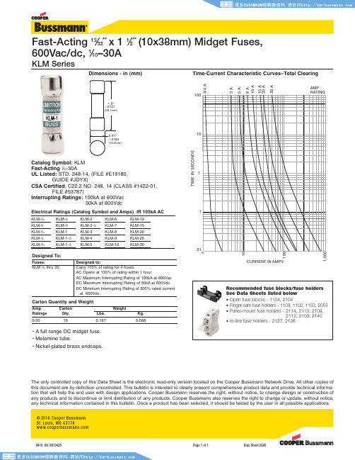
Catalog Symbol: KLM
Fast-Acting 1⁄10-30A
UL Listed: STD. 248-14, (FILE #E19180,
1
Fast-Acting 13⁄32˝ x 1 1⁄2˝ (10x38mm) Midget Fuses,
600Vac/dc, 1⁄10–30A
KLM Series
Dimensions - in (mm)
Time-Current Characteristic Curves–Total Clearing
3/4 A 3A 5A 8A 10 A 15 A 20 A 30 A
DC Minimum Interrupting Rating of 200% rated current at 600Vdc,
Carton Quantity and Weight
Amp Ratings
Carton Qty.
Lbs.
0-30
10
0.187
Weight
Kg. 0.088
• A full range DC midget fuse. • Melamine tube. • Nickel-plated brass endcaps.
GUIDE #JDYX)
CSA Certified, C22.2 NO. 248. 14 (CLASS #1422-01,
FILE #53787)
Interrupting Ratings: 100kA at 600Vac
Bussmann 断路器和熔断器数据手册说明书

O B SO LE T E SD I S C O N NE C T SW I T E S C A T A L O G 12-17-98SB98107Rev. AForm No. FD Page 1 of 2BIF Doc #1122The only controlled copy of this BIF document is the electronic read-only version located on the Bussmann Network Drive. All other copies of this document are by definition uncon-trolled. This bulletin is intended to clearly present comprehensive product data and provide technical information that will help the end user with design applications. Bussmann reserves the right, without notice, to change design or construction of any products and to discontinue or limit distribution of any products. Bussmann also reserves the right to change or update,without notice, any technical information contained in this bulletin. Once a product has been selected, it should be tested by the user in all possible applications.Catalog Symbols*:FD200J3, FD400J3, FD600J3,FD800L3Ampere Rating: 200, 400, 600, 800 Amperes Voltage Rating: 600 Volts Agency Approvals:UL Listed, Guide WPZX, File E155130CSA Certified, File 58077M9IEC 947-1General Information:Bussmann fused disconnect switches are UL 98/CSA 22.2 No. 4devices. This makes them suitable for use on service equipment,panel boards, switchboards, industrial control equipment, motor control centers, etc.*Catalog symbol is for switch only . Handles and shafts are ordered separately.FD200J3FD400J3FD600J3, FD800L3Fuse Maximum Horsepower Rating Type 200V 208V 240V 480V600VFD200J3J†505060125150FD400J3J†100125125250350FD600J3J†150150200400500FD800L3L 200200250500600†Class J fuses are standard. For 600V , Class T fuses, see table below.Class T Adapters200A BDTA2400A BDTA4600ABDTA6Components:HandlesGrip NEMA Length Padlock-Defeat-Catalog Style Type Color (Inches)Marking able ableNumber 200A ( 0.47˝ x 0.47˝)Pistol1, 3R, 12Blk4.72Off/On Yes Yes BDH53200-800A ( 0.47˝ x 0.47˝)Pistol 1, 3R, 12Blk 5.71Off/On Yes Yes BDH16Pistol 1, 3R, 4, 4X, 12Blk5.71Off/OnYesNoBDH35Terminal Lug Kits - Kit Includes 6 LugsAmp Rating Wire SizeWire Type Kit Catalog Number200#6 - 300 kcmil Cu/Al BDTL25400#2 - 600 kcmil Cu/Al BDTL26600 & 800(2) #2 - 600 kcmilCu/AlBDTL27ShaftsMounting Depth**Shaft LengthCatalog Number200 - 400 Amps ( 0.47˝ x 0.47˝)7.87 - 12.208.66BDS2209.05 - 13.389.84BDS25010.22 - 14.5411.00BDS28012.0 - 16.3212.78BDS32514.78 - 19.1015.56BDS39517.53 - 21.8518.31BDS46520.28 - 24.6221.06BDS535600 - 800 Amps ( 0.47˝ x 0.47˝)10.04 - 12.839.84BDS25011.20 - 14.0011.00BDS28012.98 - 15.7712.78BDS32515.76 - 18.5515.56BDS39518.51 - 21.3018.31BDS46521.06 - 24.0821.06BDS535**Mounting depth is the distance from the outside of door to the disconnect switch mounting plate. Shaft can be cut to desired length.Accessories:Fuse Covers and Terminal Shrouds (line-side)Switch Type Fuse Covers Terminal ShroudsAmp Fuse Catalog Catalog RatingTypeVoltage Number Number200J or T 600V BFDC200‡BDTSF2400J 600V BFDC400‡BDTSF4600, 800J or L600VBFDC600‡BDTSF6‡Fuse covers come standard on 200-800 amp switches.Auxiliary Contacts - F200 through F800Switch Aux. Contact Voltage 1 N.O. & 1 N.C. 2 N.O. & 2 N.C.Amp Rating Amp Rating Catalog Number Catalog Number200-80010600BDAUX1BDAUX2Form No. FD Page 2 of 2BIF Doc #112212-17-98SB98107Rev. A200 Amps400 AmpsDimensional Data 600 & 800 Amps。
美国BUSSMANN LPJ_SP系列低压熔断器选型手册,datasheet,图纸
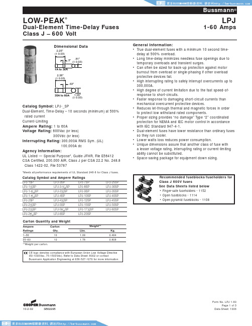
Form No. LPJ 1-60Page 1 of 3Data Sheet: 100610-2-02SB02295Catalog Symbol: LPJ-_SPDual-Element, Time-Delay – 10 seconds (minimum) at 500%rated current Current-LimitingAmpere Rating: 1 to 60AVoltage Rating: 600Vac (or less)300Vdc (or less)Interrupting Rating:300,000A RMS Sym. (UL)100,000A dcAgency Information:UL Listed — Special Purpose*, Guide JFHR, File E56412CSA Certified, 200,000 AIR, Class J per CSA 22.2 No. 248.8 Class 1422-02, File 53787*Meets all performance requirements of UL Standard 248-8 for Class J fuses.Ampere Carton Weight**Ratings Qty.Lbs.Kg.1–30101.090.49435–60101.780.808**Weight per carton.General Information:•True dual-element fuses with a minimum 10 second time-delay at 500% overload.•Long time-delay minimizes needless fuse openings due to temporary overloads and transient surges.•Can often be sized for back-up protection against motor burnout from overload or single-phasing if other overload protective devices fail.•High interrupting rating to safely interrupt overcurrents up to 300,000A.•High degree of current limitation due to the fast speed-of-response to short-circuits.•Faster response to damaging short-circuit currents than mechanical overcurrent protective devices.•Reduces let-through thermal and magnetic forces in order to protect low withstand rated components.•Proper sizing provides “no damage” Type “2” coordinated protection for NEMA and IEC motor control in accordance with IEC Standard 947-4-1.•Dual-element fuses have lower resistance than ordinary fuses so they run cooler.•Lower watts loss reduces power consumption.•Unique dimensions assure that another class of fuse with a lesser voltage rating, interrupting rating or current-Iimiting ability cannot be substituted.•Space-saving package for equipment down sizing.Dimensional DataRecommended fuseblocks/fuseholders for Class J 600V fusesSee Data Sheets listed below • Finger-safe fuseholders - 1152• Open fuseblocks - 1114• Open pyramid fuseblocks - 1108Form No. LPJ 1-60Page 2 of 3Data Sheet: 1006AMPERE RATING1A3A6A300100101.1.01T I M E I N S E C O N D S10A15A30A60A 1,000101CURRENT IN AMPERES200100Time-Current Characteristic Curves–Average Melt10-2-02SB02295®Form No. LPJ 1-60Page 3 of 3Data Sheet: 1006The only controlled copy of this Data Sheet is the electronic read-only version located on the Bussmann Network Drive. All other copies of this document are by definition uncontrolled. This bulletin is intended to clearly present comprehensive product data and provide technical information that will help the end user with design applications. Bussmann reserves the right, without notice, to change design or construction of any products and to discontinue or limit distribution of any products. Bussmann also reserves the right to change or update, without notice, any technical information containedin this bulletin. Once a product has been selected, it should be tested by the user in all possible applications.Current Limitation Curves10-2-02SB02295Form No. LPJ 70-600Page 1 of 3Data Sheet: 100710-8-03A03094.43"1.38"70A to 100A.19"Dimensional DataCatalog Symbol: LPJ-_SPDual-Element, Time-Delay – 10 seconds (minimum) at 500%rated currentCurrent-LimitingAmpere Rating:70 to 600AVoltage Rating: 600Vac (or less)*Interrupting Rating: 300,000A RMS Sym.Agency Information:UL Listed – Special Purpose†, Guide JFHR, File E56412CSA Certified, Class J per CSA C22.2 No. 248.8,Class 1422-02, File 53787*0-600A rated 300Vdc and 20 KAIC.†Meets all performance requirements of UL Standard 248-8 for Class J fuses.General Information:•True dual-element fuses with a minimum 10 second time-delay at 500% overload.•Long time-delay minimizes needless fuse openings due to temporary overloads and transient surges.•Can often be sized for back-up protection against motor burnout from overload or single-phasing if other overload protective devices fail.•High interrupting rating to safely interrupt overcurrents up to 300,000A.•High degree of current-limitation due to the fast speed-of-response to short-circuits.•Faster response to damaging short-circuit currents than mechanical overcurrent protective devices.•Reduces let-through thermal and magnetic forces in order to protect low withstand rated components.•Proper sizing provides “no damage” Type “2” coordinated protection for NEMA and IEC motor control in accordance with IEC Standard 947-4-1.•Dual-element fuses have lower resistance than ordinary fuses, hence they run cooler.•Lower watts loss reduces power consumption.•Unique dimensions assure that another class of fuse with a lesser voltage rating, interrupting rating or current-Iimiting ability cannot be substituted.•Space-saving package for equipment down sizing.450A to 600A225A to 400AForm No. LPJ 70-600Page 2 of 3Data Sheet: 1007AMPERE RATING80A 3001TI M E I N S E C O N D S100A125A200A 250A 400A600A10,0001,000100CURRENT IN AMPERES200Time-Current Characteristic Curves–Average MeltRecommended fuseblocks for Class J 600V fuses See Data Sheet: 1114®Current-Limitation CurvesForm No. LPJ 70-600Page 3 of 3Data Sheet: 1007The only controlled copy of this Data Sheet is the electronic read-only version located on the Bussmann Network Drive. All other copies of this document are by definition uncontrolled. This bulletin is intended to clearly present comprehensive product data and provide technical information that will help the end user with design applications. Bussmann reserves the right, without notice, to change design or construction of any products and to discontinue or limit distribution of any products. Bussmann also reserves the right to change or update, without notice, any technical information con-tained in this bulletin. Once a product has been selected, it should be tested by the user in all possible applications.10-8-03A03094Form No. LPJ_SPI 6-60Page 1 of 3Data Sheet: 1062 8-26-04SB04295Form No. LPJ_SPI 6-60Page 2 of 3Data Sheet: 1062Time-Current Characteristic Curves–Average Melt8-26-04SB04295AMPERE RATING6A300100101.1.01T I M E I N S E C O N D S10A15A30A60A1,000101CURRENT IN AMPERES200100®Form No. LPJ_SPI 6-60Page 3 of 3Data Sheet: 1062The only controlled copy of this Data Sheet is the electronic read-only version located on the Bussmann Network Drive. All other copies of this document are by definition uncontrolled. This bulletin is intended to clearly present comprehensive product data and provide technical information that will help the end user with design applications. Bussmann reserves the right, without notice, to change design or construction of any products and to discontinue or limit distribution of any products. Bussmann also reserves the right to change or update, without notice, any technical information containedin this bulletin. Once a product has been selected, it should be tested by the user in all possible applications.Current Limitation Curves8-26-04SB04295Form No. LPJ 70-600Page 1 of 3Data Sheet: 10638-26-04SB04295Dimensional DataCatalog Symbol: LPJ-_SPIDual-Element, Time-Delay – 10 seconds (minimum) at 500%rated currentCurrent-LimitingAmpere Rating:70 to 600A Voltage Rating: ac: 600V (or less)dc: 300V (or less)Interrupting Rating: ac: 300,000A RMS Sym.dc: 100,000AAgency Information:UL Listed – Special Purpose†, Guide JFHR, File E56412CSA Certified, Class J per CSA C22.2 No. 248.8,Class 1422-02, File 53787†Meets all performance requirements of UL Standard 248-8 for Class J fuses.General Information:•Permanent replacement fuse indication.•True dual-element fuses with a minimum 10 second time-delay at 500% overload.•Long time-delay minimizes needless fuse openings due to temporary overloads and transient surges.•Can often be sized for back-up protection against motor burnout from overload or single-phasing if other overload protective devices fail.•High interrupting rating to safely interrupt overcurrents up to 300,000A.•High degree of current-limitation due to the fast speed-of-response to short-circuits.•Faster response to damaging short-circuit currents than mechanical overcurrent protective devices.•Reduces let-through thermal and magnetic forces in order to protect low withstand rated components.•Proper sizing provides “no damage” Type “2” coordinated protection for NEMA and IEC motor control in accordance with IEC Standard 947-4-1.•Dual-element fuses have lower resistance than ordinary fuses, hence they run cooler.•Lower watts loss reduces power consumption.•Unique dimensions assure that another class of fuse with a lesser voltage rating, interrupting rating or current-Iimiting ability cannot be substituted.•Space-saving package for equipment down sizing.Recommended fuseblocks for Class J 600V fuses See Data Sheet: 1114®Form No. LPJ 70-600Page 2 of 3Data Sheet: 10638-26-04SB04295AMPERE RATING80A 300100101T I MEI NSE COND S100A 125A 200A 250A 400A 600A 1,001,000100CURRENT IN AMPERES200Time-Current Characteristic Curves–Average MeltForm No. LPJ 70-600Page 3 of 3Data Sheet: 1063®8-26-04SB04295The only controlled copy of this Data Sheet is the electronic read-only version located on the Bussmann Network Drive. All other copies of this document are by definition uncontrolled. This bulletin is intended to clearly present comprehensive product data and provide technical information that will help the end user with design applications. Bussmann reserves the right, without notice, to change design or construction of any products and to discontinue or limit distribution of any products. Bussmann also reserves the right to change or update, without notice, any technical information con-tained in this bulletin. Once a product has been selected, it should be tested by the user in all possible applications.Current-Limitation Curves。
美浦森半导体产品选型手册说明书

产品选型手册Product Selection Manual 2022.1101(Company Profile)公司发展历程0304深圳市美浦森半导体有限公司 2014年成立,总部位于深圳,是一家专业功率半导体元器件设计公司。
公司产品包括中大功率场效应管( 高中低压全系列产品, Trench MOSFET/SGT MOSFET /Super Junction MOSFET / Planar MOSFET),SiC 二极管、SiC MOSFET 等系列产品。
美浦森半导体在深圳/上海设有研发中心, 主要研发人员在产品研发和生产制程方面都具有丰富的行业经验, 平均行业经验在15年以上。
在深圳建立有半导体功率器件测试和应用实验室,主要负责产品的设计验证、参数测试、可靠性验证、系统分析、失效分析等,承担美浦森产品的研发质量验证。
目前,美浦森半导体MOSFET 和碳化硅系列产品在LED 电源、PD 电源、PC 和服务器电源、光伏逆变、UPS 、充电桩、智能家居、BLDC 、BMS 、小家电等领域得到广泛应用。
创新 高效 热爱 持续是美浦森半导体的核心价值; 用创新实现突破, 是公司不断前进的动力源泉。
专业于MOSFET 器件领域的拓展, 运用创新的电路设计和国际同步的研发技术, 成功研发出新一代MOSFET 系列产品, 产品相关性能达到行业领先水平。
我们始终坚持不断创新、不断突破, 始终保持产品第一、技术第一、服务第一的行业领先地位, 全心全意做好产品的开发与用户的极限体验 。
功率器件实验室&应用实验室投资2000万人民币兴建器件分析实验室和应用实验室, 负责美浦森产品的设计验证,品质监控和客户的技术支持。
2022年“美浦森实验室”将扩充至800平方, 并正在申请国家CNAS 认证实验室资格。
产品设计验证\产品性能比对\动静态参数测试\极限参数测试1可靠性验证\失效分析\产品品质监控2系统应用分析\系统性能验证3KEYENCE 显微镜KEYSIGHT 功率器件分析仪JUNO 直流参数测试系统ISPEC 高温反偏实验系统TEKTRONIX 功率器件动态测试仪STATEC 测试系统碳化硅全系6寸生产线升级结束, 碳化硅MOS 正式批量接单中低压Trench/SGT MOS 批量出货.超结MOS E7系列产品开始批量出货, RSP 参数超越竞品系列产品; 成立深圳器件测试及可靠性实验室、产品应用实验室.650V SiCDIODE 系列产品面市推广, 并大批量出货;1200V SiCDIODE 研发成功, 进入批量阶段; 碳化硅MOS 验证成功.2014年深圳市美浦森半导体有限公司成立,同年正式推广“美浦森”品牌MOS 系列产品.高压MOSFET (VDMOS )0605高压MOSFET (VDMOS )高压MOSFET 命名方式126245公司简称封装形式3额定电流P :TO -220F :TO -220F H:TO-247W:TO-3PD:D-Pak(TO-252)U:I-Pak(TO-251)B:D2-Pak(TO-263) I:I2-Pak(TO-262)沟道极性N:N-channel P:P-channel电压系数(x10)芯片工艺C:MOS C-FETU:MOS U-FET S:MOS S-FETUZ:MOS U-FET+ESD (Z: Zener diode)超结MOSFET (SJMOS )0708超结MOSFET 命名方式126245公司简称封装形式3额定电压P :TO -220 F :TO -220F H:TO-247W:TO-3P D:D-Pak(TO-252)U:I-Pak(TO-251)B:D2-Pak(TO-263)I :I2-Pak(TO-262)L :DFN8X8Rds (on )缩写Rds (on )数值单位:m 芯片工艺SJ:MOS SJ-FETE7:MOS E7-FET E7D:MOS FRDΩ超结产品特点Trr 时间缩短: 反向恢复时间快Qg 电荷小: 开关速度快,开关损耗小Rds (on )值小: 通态阻抗小,通态损耗小PKG体积小: 同等功率规格下封装小,有利于功率密度的提高超结MOSFET (SJMOS )27快恢复二极管(FRD)中低压MOSFET (MV/LV MOS )0910碳化硅二极管(SiC Diode)中低压命名方式126245公司简称封装形式3MOSFET电流值(1-3位数字)P:TO-220 F:TO-220FH:TO-247 W:TO-3PD:D-Pak(TO-252)U:I-Pak(TO-251)B:D2-Pak(TO-263)I :I2-Pak(TO-262)S:SOP-8 T:TSSOP-8M:DFN5X6 N:DFN3X3L:DFN8X8V:SOT-23沟通极性MOSFET电压值(2-3位数字)芯片工艺N:N-NchannelP:P-channelL:N-channel+P-channelD:Dual N-channelE:Dual P-channelT:普通Trench MOSFETG:Split Gate TrenchMOSFET27版本号只有一个版本时此为空,带ESD产品此位为K中低压MOSFET(MV/LV MOS)111213开关时间快,开关损耗小恢复时间短,Trr恢复时间短,趋近于零o工作结温高,工作温度可达到175C 以上击穿电压高,产品电压最高可达6000W 以上碳化硅MOSFET (SiC MOS )碳化硅MOSFET 命名方式5431212公司简称封装形式P :TO -220 F:TO -220F H:TO-247-3L W :TO -3P D:D-Pak(TO-252)U:I-Pak(TO-251)B:D2-Pak(TO-263)I : I2-Pak(TO-262)K: TO-247-4L453Rds(on)数值 单位: m 电压系数(X10)芯片工艺Ω碳化硅材料特点14碳化硅二极管命名方式1245公司简称封装形式3额定电流P :TO -220 F :TO -220FH:TO-247 L :DFN8X8D:D-Pak(TO-252)U:I-Pak(TO-251)B:D2-Pak(TO-263)M:DFN5x67S: SO-7N: 内绝缘工艺电压系数(X10)芯片工艺V1:JBS G1: MPS1:2Pin2P :TO -2202F :TO -220F 2H:TO-2472B:D2-Pak 2I:I2-Pak2:3Pin 2Chip2TP :TO -2202TW :TO -3P 2TH: TO-2473:2Pin 2ChipR :TO -220RF :TO-220F RH :TO -2474:3Pin 1Chip。
02生产套管和油管

222.25 49.7 73.96 725.3 14.148 0.0637
244.48 40 59.53 583.8 10.033 0.041 21305 22960
(9 5/8) 43.5 64.74 634.8 11.049 0.0452 26269 28475 30475
47 69.94 685.9 11.989 0.049 32750 35094 36542
一、套管钢级 1.API 套管钢级 API 准套管有十个钢级,即 H40、J55、K55、T95、N80、C90、C95、L80、P110、125Q。API 规范中,钢级代号后面的数值乘以 6894.757kPa(1000psi),即为套管以 kPa(或 psi)为单位的 最小屈服强度。这一规定除了极少数例外,也适应于非 API 标准的套管。 API 套管钢级的强度指标见表 2-1-1。 目前,世界上能生产 API 标准套管的有 38 个工厂,分布于 14 个国家,表 2-1-2 列出了 API 承认的厂家名单。 2.非 API 套管钢级 有的 API 标准套管的生产厂家也生产非 API 标准系列套管,非 API 标准套管是根据钻井和 采油工程需要而超出 API 标准的进一步发展。 非 API 标准套管各种钢级的强度指标见表 2-1-3。
第一节 生产套管的选择
海洋油气田开发工程中常规的套管程序包括:隔水导管、表层套管、中间技术套管(1~3 层,视井深和工程情况而定)和生产套管。
生产套管(又称油层套管)是为地下储集层中的石油或天然气流至地面创造良好的流动通 道。生产套管的重要功能是用以保护井壁、隔离各层流体,以利于油气井分层测试、分层开采 和分层改造。
177.8 23 34.23 335.7 8.052 0.0453 26407 28544
美国BUSSMANN FWX-(35-2500)A系列北美快速熔断器规格资料,选型手册,datasheet,图纸,尺寸图,安时曲线图
0.32
359
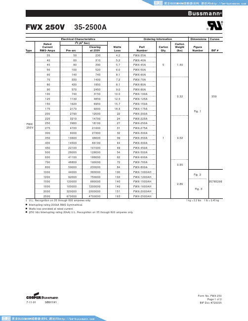
________1_2_5_______________1_1__3_0_____________4_8_5__0__________1__2_.5___________F_W__X_-_1_2_5__A_______
________1_5_0_______________1_6__2_0_____________6_9_5__0__________1__5_.7___________F_W__X_-_1_5_0__A_______
35785299 2.86
Fig. 3
2500
670000
4700000
163
FWX-2500AH
† U.L. Recognition on 35 through 800 amperes only.
1 kg = 2.2 lbs 1 lb = 0.45 kg
Ⅲ Interrupting rating 200kA RMS Symmetrical.
FWX 250V 35-2500A
Bussmann®
†
®
Type
Rated Current RMS-Amps
Electrical Characteristics
I2t (A2 Sec)
Pre-arc
Clearing at 250V
Watts Loss
Ordering Information
Part Number
1.40
_________5_0________________1__0_0______________5_2__0____________6_.0___________F_W__X_-_5_0_A_________
_________6_0________________1__4_0______________7_4__0____________8_.1___________F_W__X_-_6_0_A________________________________
美特森MPNC083CEAXX2F型号电源电路保护器说明书
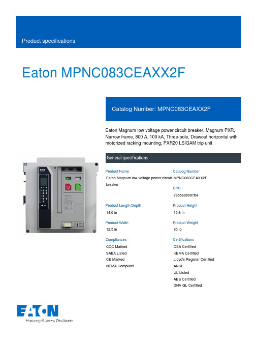
Eaton MPNC083CEAXX2FEaton Magnum low voltage power circuit breaker, Magnum PXR,Narrow frame, 800 A, 100 kA, Three-pole, Drawout horizontal withmotorized racking mounting, PXR20 LSIGAM trip unitGeneral specificationsEaton Magnum low voltage power circuitbreakerMPNC083CEAXX2F78668960976414.6 in16.8 in12.5 in95 lbCCC Marked SABA ListedCE Marked NEMA Compliant CSA CertifiedKEMA CertifiedLloyd's Register Certified ANSIUL ListedABS CertifiedDNV GL CertifiedProduct Name Catalog NumberUPCProduct Length/Depth Product Height Product Width Product Weight Compliances CertificationsNarrow Three-pole Magnum PXRNarrow Magnum PXR20 LSIG ARMSThree-pole800 A100 kAIC100 kAIC800 AZone selective interlocking application paper Magnum circuit breakers with Power Xpert Release trip units product aid Selevctive coordination application paper - IA0120000E3Magnum PXR and PD-SB double and double narrow frame UL Certificate of ComplianceMagnum PXR and PD-SB standard and narrow frame UL Certificate of ComplianceMagnum PXR low voltage power circuit breakers user manual Power Xpert Release trip unit for Magnum PXR circuit breakers PXR 20/25 user manualMicrosoft Word - Power Xpert Protection Manager Quick StartFrame Number of poles TypeFrame Series Trip TypeNumber of poles Rated uninterrupted current (Iu)Interrupt rating Interrupt rating Rated uninterrupted current (Iu)Application notesBrochuresCatalogsCertification reportsManuals and user guidesEaton Corporation plc Eaton House30 Pembroke Road Dublin 4, Ireland © 2023 Eaton. All Rights Reserved. Eaton is a registered trademark.All other trademarks areproperty of their respectiveowners./socialmediaGuide.docxPower Xpert Protection Manager x64 22.6 1 Power Xpert Protection Manager x32 22.06 1 Eaton Specification Sheet - MPNC083CEAXX2F Low voltage circuit breakers guide spec Magnum PXR 20/25 electronic trip units time current curves Molded case and low-voltage power circuit breaker health Cyber security white paperSafer by design: arc energy reduction techniquesSoftware, firmware, and applications Specifications and datasheetsTime/current curvesWhite papers。
美国BUSSMANN NON及NOS系列熔断器规格资料,选型手册
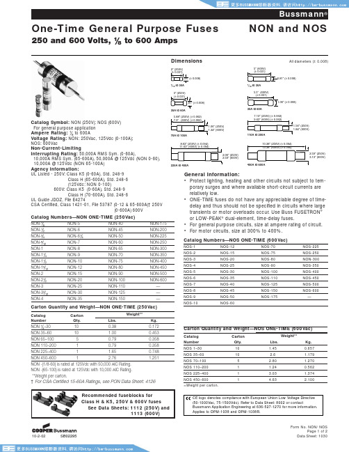
Carton Quantity and Weight—NOS ONE-TIME (600Vac)Catalog Carton Weight**Number Qty.Lbs.Kg.NOS 1–3010 1.450.657NOS 35–6010 2.6 1.179NOS 70–1005 2.80 1.270NOS 110–2001 1.240.562NOS 225–4001 3.03 1.374NOS 450–60014.632.100**Weight per carton.Form No. NON/ NOSPage 1 of 2Catalog Symbol: NON (250V); NOS (600V)Number Qty.Lbs.Kg.NON ⁄Ω•–30100.380.172NON 35–6010 1.000.453NON 65–10050.790.358NON 110–20010.790.358NON 225–4001 1.650.748NON 450–60012.761.251NON -(1/8-60) is rated at 125Vdc with 50,000 AIC Rating.NON -(65-100) is rated at 125Vdc with 10,000 AIC Rating. **Weight per carton.† For CSA Certified 15-60A Ratings, see PON Data Sheet: 4126Recommended fuseblocks for Class H & K5, 250V & 600V fuses See Data Sheets: 1112 (250V) and1113 (600V)Form No. NON/NOSThe only controlled copy of this Data Sheet is the electronic read-only version located on the Bussmann Network Drive. All other copies of this document are by definition uncontrolled. This bulletin is intended to clearly present comprehensive product data and provide technical information that will help the end user with design applications. Bussmann reserves the right, without notice, to change design or construction of any products and to discontinue or limit distribution of any products. Bussmann also reserves the right to change or update, without notice, any technical information con-tained in this bulletin. Once a product has been selected, it should be tested by the user in all possible applications.Time-Current Characteristic Curves–Average MeltNON ONE-TIME (250Vac)NOS ONE-TIME (600Vac)。
保险丝管选型指南

保险丝管选型指南
选择分析: 1. 安全认证 满足产品最终的销售和使用的地域的地安规要求。 2. 产品应用电压 保险丝的电压额定值≥有效的电路电压。 3. 最大故障电流 保险丝管的分断能力≥电路中最大故障电流 4-5. 结构尺寸(长、宽、高) 设计电路中的空间限制,安装方式 总结:满足上述要求 、结合电路特点初步选择型号。 6. 保险丝最小额定电流=正常工作电/标准类别系数 IEC标准规格:Imin =正常工作电流/0.9 UL标准规格: Imin =正常工作电流/0.75
9
保险丝管选型指南
例2:选择250V 50T 保险丝管,正常工作电流1A、机箱内温度80℃,电 路开机一次脉冲电流如下图正弦波形,脉冲电流ia=20A,持续时间 ta= 6mS,要求开关机寿命10万次。
I2T值计算:(1/2)ia2ta = (1/2)*202*0.006 =1.2A2S
10
保险丝管选型指南
3
保险丝管选型指南
7. 安装位置周区环境温度 额定值百分比-环境温度
最小额定规格值In修正: Io min = In/额定值百分 比。
4
保险丝管选型指南
例1: 在某一使用场合,实际稳态正常工作电流是1.5A,选一 慢断型,其应选的保险丝最小额定电流Imin.: 在25℃场合: Io min =实际稳态电流/0.9=1.5/0.9=1. 7A(IEC标准) =正常工作电流/0.75=1.5/0.75=2.0A(UL标准) 在80℃场合:查图表知承载能力为额定值的78% Io min =正常工作电流1.5/0.9/78%= 2.14A(IEC标准) =正常工作电流1.5/0.75/78%=2.56A (UL标准)
好利来(中国)电子科技 股份有限公司
分歧管选型
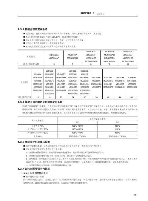
1.3.3 确定室外机容量与位置■ 综合容量配比系数,以系统的最大负荷为标准选择室外机容量,查取相对应的机组型号。
■ 室外机摆放位置应充分考虑以下几个因素:a .室外机布置在屋顶时,如有墙挡在室外机进风口,则必须在墙上开足够面积的进风口;b .室外机布置在每层阳台上时,如向上排风,要防止排气短路返回进风口;c .高层建筑,室外机宜分层设置在各层;室外机可选做高静压的机组,吹出后经百叶片导流应尽量避免引向进风口,更不宜用挡雨百叶(阻力太大),最好不用向下百叶格栅。
在必须使用格栅时,尽量选用阻力小且保证排风顺排出,前面不用挡板更好;d .室外机周围应空气流通,室外机基础应做高一些;1.3.4 制冷剂配管设计与计算1.3.4.1 制冷剂配管的设计■ 制冷剂配管设计限制由于系统沿程阻力损失、局部阻力损失,以及机组回油问题的考虑,制冷剂配管长度、室内外机高度差等存在限制,在设计系统时要特别注意,确保系统设计在规定范围内,从而保证空调系统的良好性能。
1.3.2 确定合理的室内外机容量配比系数室内外机的容量配比系数是一个系统内所有室内机额定制冷容量与室外机额定制冷容量的比值。
由于房间的使用功能不同,空调开启时间段不同,并且房间出现最大负荷的时间不同,相同时刻冷量需求不同,从经济性和节能性考虑,需根据系统覆盖的房间的同时使用系数来确定合理的室内外机的容量配比系数。
数码变容量多联机MDS 单冷型最大配比系数为130%,热泵最大为120%。
1.3.1 构建合理的空调系统■ 使用功能、使用时间段不同的房间并入同一个系统,可降低系统的峰值负荷,更加节能;■ 系统同时使用系数最好控制在50%-80%,提高系统的能效比;■ 最大负荷出现时间不同的房间并入同一系统,可有效降低外机容量;■ 室内设计条件不同的需设计不同的空调系统;■室内机数量不能超过室外机所允许连接的最大室内机数量;等效长度=实际管长度x 各弯头的等效长度+存油弯数量x各存油弯的等效长度1.3.4.2 配管尺寸计算数码变容量多联机的管道系统中,连接铜管分为主配管和支配管。
安森美 MBR7030WT D 数据表说明书
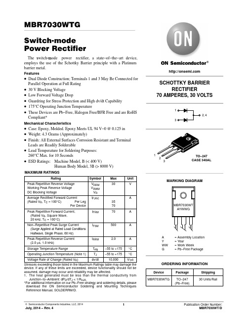
MBR7030WTGSwitch-m odePower RectifierThe s witch-m ode power rectifier, a state−of−the−art device, employs the use of the Schottky Barrier principle with a Platinum barrier metal.Features•Dual Diode Construction; Terminals 1 and 3 May Be Connected for Parallel Operation at Full Rating•30 V Blocking V oltage•Low Forward V oltage Drop•Guardring for Stress Protection and High dv/dt Capability •175°C Operating Junction Temperature•These Devices are Pb−Free, Halogen Free/BFR Free and are RoHS Compliant*Mechanical Characteristics•Case:Epoxy,Molded.EpoxyMeetsUL94V−*********•Weight: 4.3 Grams (Approximately)•Finish: All External Surfaces Corrosion Resistant and Terminal Leads are Readily Solderable•Lead Temperature for Soldering Purposes:260°C Max. for 10 Seconds•ESD Ratings: Machine Model, B (< 400 V)Human Body Model, 3B (> 8000 V)MAXIMUM RATINGSRating Symbol Max UnitPeak Repetitive Reverse Voltage Working Peak Reverse Voltage DC Blocking Voltage V RRMV RWMV R30VAverage Rectified Forward Current (Rated V R, T C = 100°C)Per LegPer Device IF(AV)3570APeak Repetitive Forward Current,(Rated V R, Square Wave,20 kHz, T C = 100°C)I FRM70ANon−Repetitive Peak Surge Current(Surge Applied at Rated Load ConditionsHalfwave, Single Phase, 60 Hz)I FSM500APeak Repetitive Reverse Current (2.0 m s, 1.0 kHz)I RRM 2.0AStorage Temperature Range T stg−55 to +175°C Operating Junction Temperature (Note 1)T J−55 to +175°C Voltage Rate of Change (Rated V R)dv/dt10,000V/m s Stresses exceeding those listed in the Maximum Ratings table may damage the device. If any of these limits are exceeded, device functionality should not be assumed, damage may occur and reliability may be affected.1.The heat generated must be less than the thermal conductivity fromJunction−to−Ambient: dP D/dT J < 1/R q JA.*For additional information on our Pb−Free strategy and soldering details, please download the ON Semiconductor Soldering and Mounting Techniques Reference Manual, SOLDERRM/D.1SCHOTTKY BARRIERRECTIFIER70 AMPERES, 30 VOLTS132, 4A= Assembly LocationY= YearWW= Work WeekG= Pb−Free PackageDevice Package Shipping ORDERING INFORMATIONMBR7030WTG TO−247(Pb−Free)30 Units/RailMARKING DIAGRAMMBR7030WTAYWWGTHERMAL CHARACTERISTICS (Per Diode)RatingSymbol Max Unit Thermal Resistance,Junction−to−CaseR q JC0.55°C/WELECTRICAL CHARACTERISTICS (Per Diode)Instantaneous Forward Voltage (Note 2)@ I F = 35 Amps, T C = 25°C @ I F = 70 Amps, T C = 25°C @ I F = 35 Amps, T C = 100°C V F0.550.720.52VInstantaneous Reverse Current (Note 2)@ Rated DC Voltage, T C = 25°C @ Rated DC Voltage, T C = 100°CI R5.0250mA Product parametric performance is indicated in the Electrical Characteristics for the listed test conditions, unless otherwise noted. Product performance may not be indicated by the Electrical Characteristics if operated under different conditions.2.Pulse Test: Pulse Width = 300 m s, Duty Cycle < 2.0%TYPICAL CHARACTERISTICSFigure 1. Typical Forward Voltage Figure 2. Typical Reverse CurrentV F , INSTANTANEOUS FORWARD VOLTAGE (VOLTS)I F , I N S T A N T A N E O U S F O R W A R D C U R R E N T (A )V R , REVERSE VOLTAGE (VOLTS)I R , R E V E R S E C U R R E N T (m A )TYPICAL CHARACTERISTICSFigure 3. Current Derating (Case)050I F (A V ), A V E R A G E F O R W A R D C U R R E N T (A )T C , CASE TEMPERATURE (°C)Figure 4. Forward Power Dissipation (Per Leg)45015I F(AV), AVERAGE FORWARD CURRENT (AMPS)P F (A V ), A V E R A G E P O W E R D I S S I P A T I O N (W A T T S )Figure 5. Typical Capacitance10203040607080510252040V R , REVERSE VOLTAGE (VOLTS)30252015105010000C , C A P A C I T A N C E (p F )3530900080007000600050004000300020001000TO −247CASE 340AL ISSUE DDATE 17 MAR 2017GENERICMARKING DIAGRAM*XXXXX = Specific Device Code A = Assembly Location Y = YearWW = Work WeekG = Pb −Free Package*This information is generic. Please refer to device data sheet for actual part marking.Pb −Free indicator, “G” or microdot “ G ”,may or may not be present.XXXXXXXXX AYWWG2XPLANENOTES:1.DIMENSIONING AND TOLERANCING PER ASME Y14.5M, 1994.2.CONTROLLING DIMENSION: MILLIMETERS.3.SLOT REQUIRED, NOTCH MAY BE ROUNDED.4.DIMENSIONS D AND E DO NOT INCLUDE MOLD FLASH. MOLD FLASH SHALL NOT EXCEED 0.13 PER SIDE. THESE DIMENSIONS ARE MEASURED AT THE OUTERMOST EXTREME OF THE PLASTIC BODY.5.LEAD FINISH IS UNCONTROLLED IN THE REGION DEFINED BY L1.6.∅P SHALL HAVE A MAXIMUM DRAFT ANGLE OF 1.5° TO THE TOP OF THE PART WITH A MAXIMUM DIAMETER OF 3.91.7.DIMENSION A1 TO BE MEASURED IN THE REGION DEFINED BY L1.DIM MIN MAX MILLIMETERS D 20.8021.34E 15.5016.25A 4.70 5.30b 1.07 1.33b2 1.65 2.35e 5.45 BSC A1 2.20 2.60c 0.450.68L 19.8020.80Q 5.40 6.20E2 4.32 5.49L1 3.81 4.32P 3.55 3.65S6.15 BSCb4 2.60 3.40F 2.655---MECHANICAL CASE OUTLINEPACKAGE DIMENSIONSON Semiconductor and are trademarks of Semiconductor Components Industries, LLC dba ON Semiconductor or its subsidiaries in the United States and/or other countries.ON Semiconductor reserves the right to make changes without further notice to any products herein. ON Semiconductor makes no warranty, representation or guarantee regarding the suitability of its products for any particular purpose, nor does ON Semiconductor assume any liability arising out of the application or use of any product or circuit, and specifically disclaims any and all liability, including without limitation special, consequential or incidental damages. ON Semiconductor does not convey any license under its patent rights nor thePUBLICATION ORDERING INFORMATIONTECHNICAL SUPPORTNorth American Technical Support:Voice Mail: 1 800−282−9855 Toll Free USA/Canada Phone: 011 421 33 790 2910LITERATURE FULFILLMENT :Email Requests to:*******************onsemi Website: Europe, Middle East and Africa Technical Support:Phone: 00421 33 790 2910For additional information, please contact your local Sales Representative。
艾森Condulet导线管体体系-铜或钢说明书
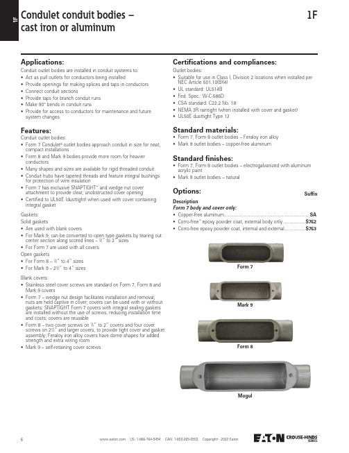
11F Condulet conduit bodies –cast iron or aluminumApplications:Conduit outlet bodies are installed in conduit systems to:• Act as pull outlets for conductors being installed• Provide openings for making splices and taps in conductors• Connect conduit sections• Provide taps for branch conduit runs• Make 90° bends in conduit runs• Provide for access to conductors for maintenance and futuresystem changesFeatures:Conduit outlet bodies:• Form 7 Condulet® outlet bodies approach conduit in size for neat,compact installations• Form 8 and Mark 9 bodies provide more room for heavierconductors• Many shapes and sizes are available for rigid threaded conduit• Conduit hubs have tapered threads and feature integral bushingsfor protection of wire insulation• Form 7 has exclusive SNAPTIGHT™ and wedge nut coverattachment to provide clear, unobstructed cover opening• Certified to UL50E (dusttight) when used with cover containingintegral gasketGaskets:Solid gaskets• Are used with blank covers• For Mark 9, can be converted to open type gaskets by tearing outcenter section along scored lines – 1/2” to 2” sizes• For Form 7 are used with all coversOpen gaskets• For Form 8 – 1/2” to 4” sizes• For Mark 9 – 21/2” to 4” sizesBlank covers:• Stainless steel cover screws are standard on Form 7, Form 8 andMark 9 covers• Form 7 – wedge nut design facilitates installation and removal;nuts are held captive in cover; covers can be used with or withoutgaskets; SNAPTIGHT Form 7 covers with integral sealing gasketsare installed without the use of screws, reducing installation timeand costs; covers are reusable• Form 8 – two cover screws on 1/2” to 2” covers and four coverscrews on 21/2” and larger covers, to provide tight cover and gasketassembly; Feraloy iron alloy covers have dome shapes for addedstrength and extra wiring room• Mark 9 – self-retaining cover screwsCertifications and compliances:Outlet bodies:• Suitable for use in Class I, Division 2 locations when installed perNEC Article 501.10(B)(4)• UL standard: UL514B• Fed. Spec.: W-C-586D• CSA standard: C22.2 No. 18• NEMA 3R raintight (when installed with cover and gasket)• UL50E dusttight Type 12Standard materials:• Form 7, Form 8 outlet bodies – Feraloy iron alloy• Mark 9 outlet bodies – copper-free aluminumStandard finishes:• Form 7, Form 8 outlet bodies – electrogalvanized with aluminumacrylic paint• Mark 9 outlet bodies – naturalForm 7Mark 9Form 8MogulOptions:SuffixForm 7 body and cover only:• Copper-free aluminum ..................................................................SA• Corro-free™ epoxy powder coat, external body only .................S752• Corro-free epoxy powder coat, internal and external ................S753Description1FA LL78 to be supplied as LL888 with two (2) RE87 reducers.LR78 to be supplied as LR888 with two (2) RE87 reducers.B Not available in copper-free aluminum (‘SA’ option).Hub sizeShapeStyle /”/”1”1/”1/”2”2/”3”3/”4”CCondulet conduit bodies – cast iron or aluminumOrdering information – threaded rigid bodies:11F Covers and gasketsOrdering information – blank covers:Ordering information – neoprene solid gaskets:Condulet conduit bodies –cast iron or aluminumSheet steelSizeCat. #Form 7wedge nutCa t. #Form 7SNAPTIGHT CICat. #Form 7 wedge nut withintegral gasket EICat. #Form 8DCat. #Form 8 withintegral gasket EI 1/”170170SG170G D DC Form 7 SNAPTIGHT covers with integral sealing gasket are installed without the use of screws.D Two cover screws on /” to 2” Form 8 covers and four cover screws on 2/” and larger Form 8 covers.E Urethane integral gaskets.F Two cover screws on /” to 1/” Form 8 covers and four cover screws on 1/” and larger Form 8 covers.G/” to 1/” are solid gaskets; 1/” to 4” are open gaskets.H/” to 2” are solid gaskets; 2/” to 4” are open gaskets.I S752 and S753 epoxy coatings are not available for any covers with integral gaskets.Sheet aluminum Feraloy iron alloyCastaluminum SizeCat. #Mark 9Ca t. #Mark 9 withintegralgasket EICa t. #Form 7Cat. #Form 7 withintegralgasket EICat. #Form 7wedge nutCat. #Form 7wedge nutwith integralgasket EICat. #Form 8FCat. #Form 7wedge nut1/”190190G170 SA170G SA170F170FG F170F SASizeCat. #Form 7Cat. #Form 8GCat. #Mark 9H1/”GASK571GASK851N GASK19411FCondulet Form 7 SnapPack conduit bodiesPre-assembled body, gasket and coverApplications:Form 7 Condulets are installed in conduit systems to:• Act as pull outlets for conductors being installed• Provide an opening for making splices and taps in conductors• Connect conduit sections• Provide taps for branch conduit runs • Make 90° bends in conduit runs• Provide access to conductors in a conduit system for maintenance and future system changesFeatures:• All SnapPack ™ product is individually bar-coded to facilitate more efficient inventory control• Distributors and end-users need to stock a single SKU instead of three separate component numbers – order the body, cover and gasket with one catalog number, saving transactioncosts, and making product selection and merchandising fast and easy• Form 7 conduit bodies are compact with a round back design for neat, efficient installations• Conduit hubs have tapered threads and integral bushings for protection of wire insulation• Many shapes and trade sizes available • Sheet steel wedge nut cover is provided with integral gasket; the wedge nutdesign facilitates installation and removal; nuts and screws are held captive in cover • Cover screws are stainless steel with a combination slotted and Phillips head, for easy installation and superior corrosion protectionStandard materials:• Body – Feraloy iron alloy • Gasket – urethane • Cover – sheet steel• Cover screws – stainless steelStandard finishes:• Feraloy – electrogalvanized with aluminum acrylic paint• Sheet steel – electrogalvanizedCertifications and compliances:• Suitable for use in Class I, Division 2 locations when installed per NEC Article 501.10(B)(4)• UL standard: UL514B• CSA standard: C22.2 No. 18• UL50E dusttight Type 12Form 7 Condulets and covers are available in additional configurations, sizes and materials. For a complete listing, refer to Form 7, Form 8 and Mark 9 conduit bodies and covers.Hub sizeShapeCat. #1/”C C17 CG Ordering information:11F Condulet conduit bodies –cast iron or aluminumDimensions (in inches):Form 7 CC shapeE shape L shapeForm 7 EHub size/”/”1”1/”1/”2”2/”3”a53/6777/83/93/12113/e3/163/164/255/166/88/88/8Form 8 CHub size/”/”1”1/”1/”2”2/”3”a511/69/75/81/103/121/155/155/e3/163/164/165/166/28/1610/810/8Mark 9 CHub size/”/”1”1/”1/”2”2/”3”3/”4”a431/511/619/75/811/105/155/155/183/183/e3/323/324/165/165/88/3210/810/813/1613/16Hub size/”/”1”a49/53/6e3/163/164/2Hub size/”/”1”1/”1/”2”a49/53/661/71/81/e3/163/164/255/166/8Form 7 L1FCondulet conduit bodies – cast iron or aluminumDimensions (in inches):Hub size/”/”1”1/”1/”2”2/”3”3/4”a 49/53/661/71/81/101/101/1211/1211/e 3/163/164/255/166/88/88/810/410/4Form 7 LL & LRForm 8 LL & LRMark 9 LL & LRForm 7 LBLB shapeLL shape LR shapeHub size/”/”1”1/”1/”2”2/”3”3/4”a 415/59/615/717/91/111315/1315/167/167/e 3/163/164/165/166/28/1610/810/813/1613/16Form 8 LBHub size/”/”1”1/”1/”2”2/”3”3/4”a 419/51/63/73/725/103/1315/1315/167/167/e 3/323/324/165/165/88/3210/810/813/1613/16Mark 9 LBHub size/”/”1”1/”1/”2”2/”3”3/4”a 49/53/661/71/81/101/101/1211/1211/e 3/163/164/255/166/88/88/810/410/4Hub size/”/”1”1/”1/”2”2/”3”a 415/59/615/717/91/111315/1315/e 3/163/164/165/166/28/1610/810/8Hub size/”/”1”1/”1/”2”2/”3”3/4”a 419/51/63/73/751/103/1315/1315/167/167/e 3/323/324/165/165/88/3210/810/813/1613/1611F Condulet conduit bodies –cast iron or aluminumDimensions (in inches):TA shapeT shapeForm 7 TAForm 7 TTB shapeForm 7 TBHub size a b c d e1/”55/13/27/15/33/Form 8 THub size a b c d e1/”511/13/25/135/Mark 9 THub size a b c d e1/” 5 113/21/11/39/Hub size a b c d e1/”55/25/27/15/33/Hub size a b c d e1/”55/25/19/15/33/Form 8 TBHub size a b c d e1/”511/217/13/135/Mark 9 TBHub size a b c d e1/”511/233/13/ 1 35/Hub size A B C D EF (bendradius)1/”71/11/311/15/33/ 4.4Form 7 UU shape1FCondulet conduit bodies – cast iron or aluminumDimensions (in inches):X shapeForm 7 XHub sizeabcde1/”55/35/13/15/33/Form 8 XHub sizeabcde1/”511/229/13/135/Mark 9 XHub sizeabcde1/”511/257/13/ 1 35/1”7/163/22/41/84/16。
酸氢化物气管管道系列产品说明书
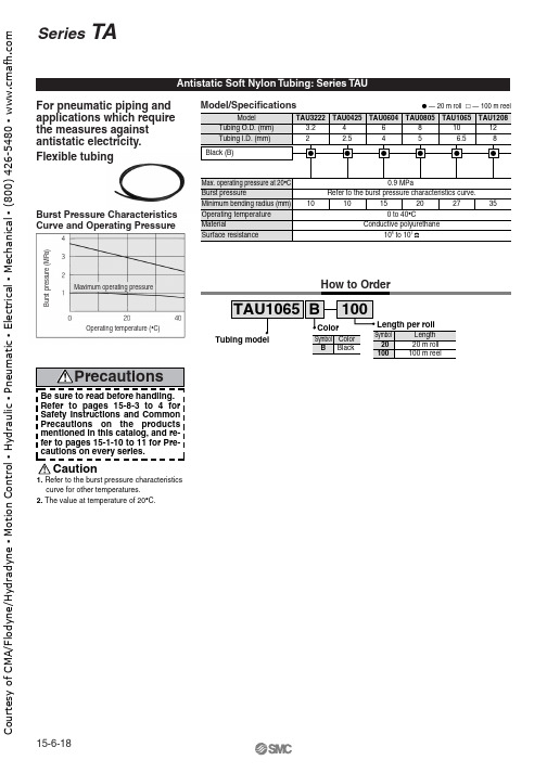
Max. operating pressure at 20Burst pressureMinimum bending radius (mm)Operating temperature MaterialSurface resistanceBurst Pressure Characteristics Curve and Operating PressureBe sure to read before handling.Refer to pages 15-8-3 to 4 for Safety Instructions and Common Precautions on the products mentioned in this catalog, and re-fer to pages 15-1-10 to 11 for Pre-cautions on every series.1. Refer to the burst pressure characteristics PrecautionsFlexible tubingB u r s t p r e s s u r e (M P a )Operating temperature (°C)Maximum operating pressureCautionSafety InstructionsThese safety instructions are intended to prevent a hazardous situation and/or equipment damage. These instructions indicate the level of potential hazard by labels of "Caution", "Warning" or "Danger". To ensure safety, be sure to observe ISO 4414 Note 1), JIS B 8370 Note 2) and other safety practices.1. The compatibility of pneumatic equipment is the responsibility of the personwho designs the pneumatic system or decides its specifications.Since the products specified here are used in various operating conditions, their compatibility for the specific pneumatic system must be based on specifications or after analysis and/or tests to meet your specific requirements. The expected performance and safety assurance will be the responsibility of the person who has determined the compatibility of the system. This person should continuously review the suitability of all items specified, referring to the latest catalog information with a view to giving due consideration to any possibility of equipment failure when configuring a system.2.Only trained personnel should operate pneumatically operated machineryand equipment.Compressed air can be dangerous if an operator is unfamiliar with it. Assembly, handling or repair of pneumatic systems should be performed by trained and experienced operators.3. Do not service machinery/equipment or attempt to remove components untilsafety is confirmed.1. Inspection and maintenance of machinery/equipment should only be performed once measures to prevent falling or runaway of the driver objects have been confirmed.2. When equipment is to be removed, confirm the safety process as mentioned above. Cut the supply pressure for this equipment and exhaust all residual compressed air in the system.3. Before machinery/equipment is restarted, take measures to prevent shooting-out of cylinder piston rod, etc.4. Contact SMC if the product is to be used in any of the following conditions:1. Conditions and environments beyond the given specifications, or if product is used outdoors.2.Installation on equipment in conjunction with atomic energy, railway, air navigation, vehicles, medical equipment, food and beverages, recreation equipment, emergency stop circuits, clutch and brake circuits in press applications, or safety equipment.3. An application which has the possibility of having negative effects on people, property, or animals, requiring special safety analysis.Note 1)ISO 4414: Pneumatic fluid power--General rules relating to systems.Note 2)JIS B 8370: General Rules for Pneumatic EquipmentWarningCaution :Operator error could result in injury or equipment damage.Warning :Operator error could result in serious injury or loss of life.Danger :In extreme conditions, there is a possible result of serious injury or loss of life.15-18-3C o u r t e s y o f C M A /F l o d y n e /H y d r a d y n e ▪ M o t i o n C o n t r o l ▪ H y d r a u l i c ▪ P n e u m a t i c ▪ E l e c t r i c a l ▪ M e c h a n i c a l ▪ (800) 426-5480 ▪ w w w .c1. Confirm the specifications.Products represented in this catalog are designed for use in compressed air appllications only (including vacuum), unless otherwise indicated.Do not use the product outside their design parameters.Please contact SMC when using the products in applications other than compressed air (including vacuum).4. Use clean airIf the compressed air supply is contaminated with chemicals, cynthetic materials, corrosive gas, etc., it may lead to break down or malfunction.SelectionMountingPipingAir SupplyMaintenanceOperating EnvironmentWarning1.Instruction manualInstall the products and operate them only after reading the instruction manual carefully and understanding its contents. Also keep the manual where it can be referred to as necessary.2. Securing the space for maintenanceWhen installing the products, please allow access for maintenance.3. Tightening torqueWhen installing the products, please follow the listed torque specifications.Warning1.Do not use in environments where the product is directly exposed to corrosive gases, chemicals, salt water, water or steam.2.Do not expose the product to direct sunlight for an extended period of time.3.Do not use in a place subject to heavy vibrations and/or shocks.4.Do not mount the product in locations where it is exposed to radiant heat.Warning1.Maintenance procedures are outlined in the operation manual.Not following proper procedures could cause the product to malfunction and could lead to damage to the equipment or machine.2. Maintenance workIf handled improperly, compressed air can be dangerous.Assembly, handling and repair of pneumatic systems should be performed by qualified personnel only.3. Drain flushingRemove drainage from air filters regularly. (Refer to the specifications.)4. Shut-down before maintenanceBefore attempting any kind of maintenance make sure the supply pressure is shut of and all residual air pressure is released from the system to be worked on.5. Start-up after maintenance and inspectionApply operating pressure and power to the equipment and check for proper operation and possible air leaks. If operation is abnormal, please verify product set-up parameters.6. Do not make any modifications to be product.Do not take the product apart.Warning1. Before pipingMake sure that all debris, cutting oil, dust, etc, are removed from the piping.2. Wrapping of pipe tapeWhen screwing piping or fittings into ports, ensure that chips from the pipe threads or sealing material do not get inside the piping. Also, when the pipe tape is used, leave 1.5 to 2 thread ridges exposed at the end of the threads.Caution1. Operating fluidPlease consult with SMC when using the product in applications other than compressed air (including vacuum).Regarding products for general fluid, please ask SMC about applicable fluids.2. Install an air dryer, aftercooler, etc.Excessive condensate in a compressed air system may cause valves and other pneumatic equipment to malfunction.Installation of an air dryer, after cooler etc. is recommended.3. Drain flushingIf condensate in the drain bowl is not emptied on a regular basis, the bowl will over flow and allow the condensate to enter the compressed air lines.If the drain bowl is difficult to check and remove, it is recommended that a drain bowl with the auto-drain option be installed.For compressed air quality, refer to “Air Preparation Equipment” catalog.WarningCommon PrecautionsBe sure to read before handling.For detailed precautions on every series, refer to main text.15-18-4C o u r t e s y o f C M A /F l o d y n e /H y d r a d y n e ▪ M o t i o n C o n t r o l ▪ H y d r a u l i c ▪ P n e u m a t i c ▪ E l e c t r i c a l ▪ M e c h a n i c a l ▪ (800) 426-5480 ▪ w w w .c m a f h .c o m。
Eaton HFD3070LS06 型号 C 完整型号电路保护器说明说明书
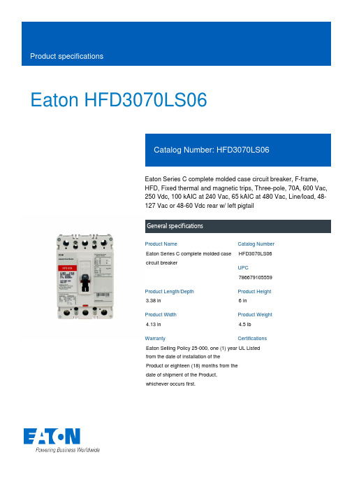
Eaton HFD3070LS06Eaton Series C complete molded case circuit breaker, F-frame, HFD, Fixed thermal and magnetic trips, Three-pole, 70A, 600 Vac, 250 Vdc, 100 kAIC at 240 Vac, 65 kAIC at 480 Vac, Line/load, 48-127 Vac or 48-60 Vdc rear w/ left pigtailGeneral specificationsEaton Series C complete molded case circuit breakerHFD3070LS067866791055593.38 in 6 in4.13 in 4.5 lb Eaton Selling Policy 25-000, one (1) year from the date of installation of the Product or eighteen (18) months from the date of shipment of the Product, whichever occurs first.UL Listed Product NameCatalog Number UPCProduct Length/Depth Product Height Product Width Product Weight WarrantyCertificationsSeries C100 kAIC at 240 Vac65 kAIC at 480 VacFHFD48-127 Vac or 48-60 Vdc left pigtail rear 50/60 HzComplete breakerLine and load600 Vac, 250 Vdc70AFixed thermal, fixed magneticThree-pole Application of Multi-Wire Terminals for Molded Case Circuit BreakersUL listed 100%-rated molded case circuit breakersApplication of Tap Rules to Molded Case Breaker TerminalsCircuit breaker motor operators product aidMOEM MCCB Product Selection GuideMotor protection circuit breakers product aidPlug-in adapters for molded case circuit breakers product aid StrandAble terminals product aidCurrent limiting Series C molded case circuit breakers product aidMulti-wire lugs product aidPower metering and monitoring with Modbus RTU product aid Counterfeit and Gray Market Awareness GuideBreaker service centersEaton's Volume 4—Circuit ProtectionMolded case circuit breakers catalogTime Current Curves for Series C® F-Frame Circuit BreakersInstallation Instructions for EHD, EDB, EDS, ED, EDH, EDC, FDB, FD, HFD, FDC, HFDDC Circuit Breakers and Molded Case SwitchesCircuit Breakers ExplainedCircuit breakers explainedMOEM MCCB product selection guideSeries C G-Frame molded case circuit breakers time current curves Series C J-Frame molded case circuit breakers time current curvesEaton Specification Sheet - HFD3070LS06Series C F-Frame molded case circuit breakersSeriesInterrupt ratingFrameCircuit breaker type Shunt tripFrequency ratingCircuit breaker frame type TerminalsVoltage rating Amperage RatingTrip TypeNumber of poles Application notesBrochuresCatalogsDrawingsInstallation instructions MultimediaSpecifications and datasheetsEaton Corporation plc Eaton House30 Pembroke Road Dublin 4, Ireland © 2023 Eaton. All Rights Reserved. Eaton is a registered trademark.All other trademarks areproperty of their respectiveowners./socialmedia。
安森美半导体高能效电源方案选型指南电子书
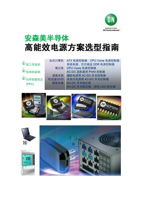
本电子书重点围绕台式计算机、笔记本 AC-DC 适配器、液晶电视及 智能电表等应用,分析相关应用要求及技术趋势,并介绍安森美半导 体相应的高能效电源解决方案, 帮助客户更好地选用安森美半导体的 产品及方案,用于开发高能效的电子产品,符合或超越各种能效规范 标准,增强产品的卖点及竞争力。
1
安森美半导体
高能效电源方案选型指南
高工作效率 低待机能耗 功率因数校正
(PFC) 台式计算机 笔记本 液晶电视 机顶盒/DVD 智能电表 ATX 电源控制器,CPU Vcore 电源控制器 系统电源、芯片组及 DDR 电源控制器 CPU Vcore 电源控制器 AC-DC 适配器用 PWM 控制器 辅助电源用 AC-DC 开关控制器 开放式电源用 AC-DC 开关控制器 AC-DC 开关稳压器 DC-DC 开关稳压器,线性 LDO 稳压器
第三章:300 W 纤薄液晶电视主电源 GreenPoint®参考设计 ................................................... 11
第四章:安森美半导体高能效智能电表电源方案..................................................................... 12 一、提供高能效及低待机能耗的 AC-DC 开关稳压器 ........................................................ 13 二、提供不同电流电平的 DC-DC 开关稳压器 .................................................................... 14 三、提供不同电流电平的线性 LDO 稳压器 ........................................................................ 15 四、安森美半导体应用于智能电表的其它解决方案......................................................... 15 五、小结:...................................................................................................... 16
美国Eaton公司Bussmann系列PVS-R保护器产品说明说明书

PVS-R-40 PVS-R-50 PVS-R-60 PVS-R-70
PVS-R-80 PVS-R-90 PVS-R-100 PVS-R-125
PVS-R-150 PVS-R-175 PVS-R-200 PVS-R-225
PVS-R-250 PVS-R-300 PVS-R-350 PVS-R-400
• Maximize return on investment with fuses proven to withstand harsh temperatures.
• Minimize design time, operating outage time and replacement costs with fuses qualified in excessively changing environmental conditions.
CSA is a registered trademark of the Canadian Standards Group. UL is a registered trademark of the Underwriters Laboratories, Inc.
For Eaton’s Bussmann series product information, call 1-855-287-7626 or visit: /bussmannseries
PVS-R fuses are Class RK5 fuses and are available in a range of 20-400 amps, all rated at 600Vac/dc.
Eaton is committed to developing products that offer superior protection for PV installations.