AT001D3-24中文资料
ATD中文说明书

TurboMatrix 100/150/300/350/650 ATD/TD用户说明书目录第一章前言 (7)前言 (8)关于本手册 (9)用于本仪器的标识 (10)仪器拆箱 (10)安全信息 (13)电器安全 (13)电磁兼容性(EMC) (15)机械伤害 (15)化学药品 (16)压缩气 (17)极端温度 (18)废品处置 (19)PerkinElmer产品符合WEEE条例 (19)第二章安装和调试 (21)前言 (22)预安装清单: (22)实验室要求 (23)操作环境 (23)仪器空间要求 (25)电路连接 (26)交流线路连接 (26)电涌 (28)ATD和TD与气相色谱的连接 (28)电路连接 (29)ATD/TD输入/输出端口 (29)TD输出信号 (30)ATD/TD输入信号 (32)ATD/TD连到AutoSystem XL GC或Clarus 500 上 (34)ATD/TD连到其他GC除HP 5890和HP6890 (35)ATD/TD连到HP 5890、HP 6890 (36)安装加热传输线 (37)直接连到TD上的毛细管分析柱 (38)通过GC后面板安装 (39)通过GC进样口安装 (41)安装ATD/TD (42)检漏测试 (43)通过GC后面板安装传输线 (45)连接填充柱 (49)毛细管直接连到TD上 (51)连接ATD/TD的供气系统 (52)供气规格 (53)气体连接 (54)设定载气流速 (58)设定GC柱头压 (59)对TurboMatrix Series 100 TD和150 ATD气体力学手册设定解吸附流速和进样分流流速 (60)设定出口分流 (61)第三章操作 (63)操作 (64)手动气路控制自动热脱附仪TurboMatrix Series100 TD 和 150 ATD (68)创建序列Sequence (69)编辑一个序列 (71)状态标签 (71)温度标签Temp (71)时间标签 (73)选项标签 (76)操作模式 (78)二级解吸和吸附管老化 (79)气路控制标签PNU (79)日志标签Log (80)工具Tools (81)参数Preferences (84)参数标签Preferences (85)运行标签Run (85)配置标签Config (86)设置标签Setup (88)连接标签Connect (90)装载吸附管 (91)在TD上装载单支吸附管 (92)TD的单方法操作 (92)ATD的单方法操作 (93)电子气路控制(PPC)热脱附仪TurboMatrix Series 300 TD,350ATD和650 ATD (95)系统设置 (95)单方法操作 (96)创建一个序列 (97)编辑序列 (98)装载吸附管 (122)TD的单方法操作 (124)ATD的单方法操作 (124)第四章附件 (127)附件选择板 (128)时间事件 (128)BCD接口 (129)吸附管和密封帽 (130)液氮制冷(LN2) (133)内标组件 (134)操作原理 (135)IS组件的操作 (136)IS操作常识 (136)选择内标 (137)设置IS流速 (137)TD控制软件 (140)连续吸附管采样仪(STS 25) (140)在线采样配件 (141)第五章方法开发 (142)分析目标 (143)优化初级解吸(吸附管) (143)优化二级解吸(冷阱) (144)设置系统参数 (144)高温操作 (149)载气流速 (150)选择吸附剂 (151)吸附剂性能测定 (154)冷阱吸附剂的选择 (157)设置样品分流比 (158)确定适宜的整体分流比 (159)校准热解吸系统 (162)气化液体标准 (163)吸附管上液体标准的直接注射 (163)内标注射组件 (164)标准气体主动式采样 (164)校准数据处理系统 (165)样品完整性测试 (165)样品回收 (165)第六章日常维护 (167)日常维护 (168)清洗仪器 (169)清洗和净化 (169)常规实验室卫生 (169)载气 (170)吸附剂的贮存 (170)样品管核贮存盖 (170)质谱使用要求 (171)取掉和更换ATD前门 (171)更换固定和移动密封件中的O型圈 (173)更换固定密封装配中O型圈和过滤板 (173)替换TD可动密封件中O型圈和过滤板 (175)替换ATD可动密封件中O型圈和过滤板 (176)检漏测试 (178)标准检漏 (179)电阻校准 (180)柱检漏测试 (180)气相温度校准 (181)环境压力校准 (182)对TurboMatrix 650 ATD的采样管和捕集阱阻抗进行校准 (185)取下并更换冷阱 (192)取下冷阱 (193)更换冷阱 (198)冷阱维护 (199)调节冷阱 (200)冷阱除冰 (200)重填冷阱 (201)更换阱过滤板 (203)不锈钢管 (206)玻璃管和玻璃内衬不锈钢管 (206)装网配件 (206)调节填好的样品管 (208)填充管的贮存和寿命 (210)清洗ATD样品盘 (210)更换保险丝 (211)第七章热解吸理论 (214)手动气路控制 (215)电子气路控制(PPC) (215)操作模式 (216)冷阱吹扫模式 (217)吸附管活化(老化) (217)二级解吸—样品分析 (219)吸附管解吸交叉 (222)自动检漏 (222)吸附管检漏加压 (222)吸附管的初次和二次检漏 (223)冷阱检漏 (224)检漏确认次数 (224)吸附管的载气吹扫 (224)冷阱解吸配置 (226)单级解吸和二级解吸 (226)二级解吸(PerkinElmer ATD) (227)热解吸的应用 (228)环境监测 (228)液体和固体基质中挥发性有机组分的提取 (228)热解吸技术的局限性 (229)第八章采样技术 (230)介绍 (231)扩散采样理论 (231)PerkinElmer吸附管的扩散速率 (234)扩散式监测应用 (234)Up =1.5 (237)吹扫捕集 (239)土壤探测 (239)PerkinElmer GC标准物质吸附管 (240)热解吸直接进样 (241)液体和乳剂进样 (241)树脂和膏状物进样 (242)固体进样 (242)第九章故障维修 (244)故障维修 (245)状态信息 (245)仪器故障情况 (252)故障:空气压太低 (252)故障:载气压太低 (252)故障:转盘电机停转 (253)故障:机械臂电机停转 (253)故障:1、2、3或4区的传感器失灵 (253)故障:缺管 (254)故障:从头到尾没有管 (254)故障:管载入失败 (255)故障:管卸载失败 (255)故障:转盘不能指向 (256)故障:转盘位置、去盖位置或解吸附位置的臂失灵 (256)故障:找不到转盘 (256)故障:臂不能伸出 (256)故障:臂不能缩回 (257)故障:夹子合不拢 (257)故障:夹子打不开 (258)故障:管盖盖不上 (258)故障:管盖打不开 (259)故障:管炉在Tube Position出错 (259)故障:管炉在Idle Position出错 (259)故障:管炉在Cool Position出错 (260)故障:密封件不能上升 (260)故障:密封件不能到中位 (260)故障:密封件不能下降 (260)故障:初始化失败 (260)故障:管检漏失败 (261)故障:阱检漏测试失败 (261)故障:用户必须清除盖子 (261)故障:用户必须清除管 (262)故障:Valco-A、B、C或D阀失败 (262)重大错误 (262)峰展宽和峰分叉 (263)冷阱不能制冷 (264)样品残留 (265)系统污染 (266)回收不好或样品损失 (268)区分覆盖宽沸点范围的化合物 (270)第一章 前言前言注意:此用户说明书中,TD代表单管热脱附仪,ATD代表50根管热脱附仪。
Advance Optima - Modbus 30 24-310-1说明书
ModbusFunctions and ComponentsTechnical Information 30/24-310-1 ENTable of ContentsPageChapter 1Overview3 Introduction3Modbus-Frames and Functions4IEEE 754-Format5Modbus Addresses and Data Format6Chapter 2 Connecting11 Modbus Connection via RS 232C11Modbus Connection via RS 48512Chapter 3 Components for the network14 Components for RS-485 Interface142Technical Information Advance Optima – Modbus30/24-310-1 ENIntroductionDescription The Advance Optima Modbus is used to transfer information from the analyzer to a PLC, DCS or any other device that has an appropriate interface. Measurementvalues, status signals and also signals of analog and digital inputs and outputs arethus available for further usage.In accordance with Optima M-DDE the signals can be integrated into standardsoftware under Windows 95/NT (e.g. Excel, Visual Basic or LabView). You canobtain the Windows-driver Optima M-DDE for free at ABB Analytical.RTU mode This Technical Information is based on the Gould Modbus Protocol Reference Guide (January, 1985). The Advance Optima devices support the Modbus slave protocolwith RTU (Remote Terminal Unit) mode.Two interfaces Two interfaces are available, where only one can be operated at a time.•RS-485•RS-232C(Advance Optima software version ≥ 1.2)Both versions are explained in Chapter 2.Read Write ExampleMeasurement values x–CO, NO, H2, etc.Digital Inputs x–for indication of external status signals Digital Outputs x–for control of solenoid, pumps, etc.Analog Inputs x–for indication of mA-values of externalanalyzersAnalog Outputs x–for indication of mA-values of measurementvalues or calculated values (function blockapplication)Modbus Digital Inputs x x for control of Advance Optima functions asauto calibration, measuring range control, etc.after function block configurationModbus Digital Outputs x–for indication of all functions such as alarm signaling etc. integrated by function blockconfigurationStatus x–indication of error, maintenance mode,maintenance request30/24-310-1 EN Technical Information Advance Optima – Modbus3Modbus-Frames and FunctionsData transfer For data transfer a combination of frames is used, that consists of 1/0 information,united to one or more telegrams.Frame The transfer values are decomposed in bytes (= 8 bit). Each of these bytes iscompleted by one start-bit, possibly one parity-bit (even number of …1“) and onestop-bit. In the following description the term …byte“ will be used, even if ten oreleven bits will be transferred including the start-, stop- and parity-bits.Telegrams The Modbus-telegrams consist of the following frames:address (1 byte), function (1 byte), data (n bytes) and check sum (2 bytes).The telegrams also take on the …shake-hands-function“: each telegram from masterto slave must be responded, before a new telegram is allowed to be transmitted.The computer has to have in a adequate supervision, for excluding non answeringbus participants (time-out-supervision).Admissible addresses As addresses for the participants of the bus the numbers 1...255 are admitted.The address 0 is the global address (broadcast-address). When this address will beused in a telegram, all participants accept this telegram without an acknowledgmentto the master.Functions Code Term Function01Read coil status Reading of binary values of type coil02Read input status Reading of binary values of type status03Read holding registers Reading of 16 bit holding-registers04Read input registers Reading of 16 bit input-registers05Force single coil Setting of a single binary value06Preset single register Set of a single 16 bit-register; for DINT orREAL two telegrams are necessary08Loopback diagnostic test Testing telegram for diagnostics of thecommunication capability of slave15Force multiple coils Set of several successive binary values16Preset multiple registers Set of several successive 16 bit-registers Check sum The check sum is calculated over all bytes of one telegram without the start-, stop-and parity-bits.Transfer rules The neutral position of the data line corresponds with the logical …1“.A distance of more than 3.5 bytes, however at least 10 ms is defined as separationbetween two telegrams. For the beginning of the data transfer the neutral position ofthe data line must be observed.4Technical Information Advance Optima – Modbus30/24-310-1 ENIEEE 754-FormatModbus-protocol and IEEE 754-Format The Modbus-protocol allows only 16-bit-registers as transfer values. Some of the Advance Optima-data is stored in the IEEE 754-Format (32 bit). For this reason the data must be processed by the interrogating device..Construction of IEEE-Format Term Numberof bitsMeaningS1Sign bit; explains the sign (0 = positive, 1 = negative)E8Two’s complement exponent. The true value is theexponent minus 127.M23The …most significant bit“ of the normalized mantissa beforethe decimal point is implicitly 1, but is not stored. The valuerange is also between 1.0 (included) and 2.0.Example The number –12.5 is stored as the hexadecimal value 0xC1480000. The followingtable shows the storage configuration:Address+0+1+2+3format SEEEEEEE EMMMMMMM MMMMMMMM MMMMMMMMbinary11000001010010000000000000000000hexadecimal C1480000Explanations•The sign bit is 1, i.e. the value is negative.•The exponent is 10000010 binary, which corresponds to the decimal value 130.Subtracting 127 from 130 leaves 3, which is the actual exponent.•The stored mantissa value is 10010000000000000000000. Adding the non stored1 before the decimal point gives the value 1.10010000000000000000000.•After adjusting the mantissa to the exponent (moving it three places) the result is1100.10000000000000000000. This binary number corresponds to the decimalvalue 12.5. Finally the sign bit needs to be taken into account. This makes the finalvalue of –12.5.30/24-310-1 EN Technical Information Advance Optima – Modbus5Modbus Addresses and Data FormatPrinciple The Advance Optima analyzer system is modular and very flexible. A system couldconsist of one or more analyzer modules which in itself could measure one or morecomponents. It is also possible to connect different kinds of I/O-boards to a system.For this reason the Modbus addressing schema is not static.Data format There are five flexible groups and three fixed length groups of information defined in an Advance Optima system.The grouped information can be read through …Single-Modbus-Request“.Flexible groups The flexible groups are:•Measuring Values•Analog Inputs (AI)•Analog Outputs (AO)•Digital Inputs (DI)•Digital Output (DO)Each flexible group has a fixed start address and a variable length of elements –depending on the system.Fixed length groups The fixed length groups are:•Status (Error, Maintenance Request, Maintenance Mode)•Modbus Digital Input (8x)•Modbus Digital Output (8x)Addressing example The addressing example below is based on a system with three analyzer modulesand two analog I/O-Boards. Analyzer 1 has three components, analyzer 2 has onecomponent and analyzer 3 has two components.Continued on next page6Technical Information Advance Optima – Modbus30/24-310-1 ENMeasurement values The measurement values are transmitted in the IEEE 32 bit standard floating point format. The floating point format is not a part of the Modbus specification. AdvanceOptima devices use two word registers to represent a floating point value (ordering:high word, low word).Modicon Modbus-Address Type RegisterNumberDescription/Name30001 30002Input register01Analyzer 1 - Component 130003 30004Input register23Analyzer 1 - Component 230005 30006Input register45Analyzer 1 - Component 330007 30008Input register67Analyzer 2 - Component 130009 30010Input register89Analyzer 3 - Component 130011 30012Input register1011Analyzer 3 - Component 2etc.Analog Inputs (AI)Analog Inputs are also transmitted in the IEEE 32 bit standard floating point format.The floating point format is not a part of the Modbus specification. Advance Optimadevices use two word registers to represent a floating point value (high word, lowword).Modicon Modbus-Address Type RegisterNumberDescription/Name30100 30101Input register99100Analog I/O-Board 1 V-in 130102 30103Input register101102Analog I/O-Board 1 I-in 130104 30105Input register103104Analog I/O-Board 1 V-in 230106 30107Input register105106Analog I/O-Board 1 I-in 230108 30109Input register107108Analog I/O-Board 2 V-in 130110 30111Input register109110Analog I/O-Board 2 I-in 130112 30113Input register111112Analog I/O-Board 2 V-in 230114 30115Input register113114Analog I/O-Board 2 I-in 2etc.Continued on next page30/24-310-1 EN Technical Information Advance Optima – Modbus7Analog Outputs (AO)Analog Inputs are also transmitted in the IEEE 32 bit standard floating point format.The floating point format is not a part of the Modbus specification. Advance Optimadevices use two word registers to represent a floating point value (high word, lowword).Modicon Modbus-Address Type RegisterNumberDescription /Name30300 30301Input register299300Syscon AO 130302 30303Input register301302Syscon AO 230304 30305Input register303304Analog I/O-Board 1 AO 130306 30307Input register305306Analog I/O-Board 1 AO 230308 30309Input register307308Analog I/O-Board 2 AO 130310 30311Input register309310Analog I/O-Board 2 AO 230312 30313Input register311312Analog I/O-Board 3 AO 130314 30315Input register313314Analog I/O-Board 3 AO 2etc.Digital Inputs (DI)The Modbus master has only read access to digital input values.Modicon Modbus-Address Type InputNumberDescription/Name10016input status15Syscon DI 110017input status16Syscon DI 210018input status17Syscon DI 310019input status18Syscon DI 410020input status19Syscon DI purge10021input status20AI/O-Board 1 DI 110022input status21AI/O-Board 1 DI 210023input status22AI/O-Board 2 DI 110024input status23AI/O-Board 2 DI 2etc.Continued on next page8Technical Information Advance Optima – Modbus30/24-310-1 ENDigital Outputs (DO)The Modbus master has only read access to digital output values.Modicon Modbus-Address Type InputNumberDescription/Name11036input status1035Syscon DO 111037input status1036Syscon DO 211038input status1037Syscon DO 311039input status1038Syscon DO 411040input status1039AI/O-Board 1 DO 111041input status1040AI/O-Board 1 DO 211042input status1041AI/O-Board 2 DO 111043input status1042AI/O-Board 2 DO 2etc. Status The Modbus master has read access to the three global status values.Modicon Modbus-Address Type InputNumberDescription/Name10001input status0Error10002input status1Maintenance Mode 10003input status2Maintenance RequestModbus Digital Inputs (DI)Modbus Digital Inputs are bit variables in the analyzer. The Modbus master has read and write access to these variables. The Modbus DI can be linked like a physical (…real“) DI in a function block configuration. The master has access to eight variables and uses function code 1 to read and 5 or 15 to write the variables.Modicon Modbus-AddressType CoilNumberDescription/Name1Coil status0Modbus-DI12Coil status1Modbus-DI23Coil status2Modbus-DI34Coil status3Modbus-DI45Coil status4Modbus-DI56Coil status5Modbus-DI67Coil status6Modbus-DI78Coil status7Modbus-DI8Continued on next page30/24-310-1 EN Technical Information Advance Optima – Modbus9Modbus Digital Outputs (DO)Modbus Digital Outputs are bit variables in the analyzer which can only be read by the Modbus master. The Modbus DO can be linked like a physical DO in a function block configuration.Modicon Modbus-AddressType InputNumberDescription/Name 12060input status2059Modbus-DO112061input status2060Modbus-DO212062input status2061Modbus-DO312063input status2062Modbus-DO412064input status2063Modbus-DO512065input status2064Modbus-DO612066input status2065Modbus-DO712067input status2066Modbus-DO810Technical Information Advance Optima – Modbus30/24-310-1 EN30/24-310-1 EN Technical Information Advance Optima – Modbus 11Modbus Connection via RS 232CConnectingYou can connect the Modbus master to the RS-232C interface of the systemcontroller (software version ≥ 1.2). The RS-232C connection only provides a point to point access (e.g. Advance Optima and a PC).Figure 1Connection via RS 232CWhich material isnecessary?Use cables with standard-RS-232C access for connecting.The pin configuration is depicted below:Figure 2RS-232C interface2RxD 3TxD 5GNDtype: 9 contacts Sub-D-connectorInterface settings The settings for data transmission are•19200 baud •no parity •1 stopbitFThese settings can be changed in software versions ≥ 1.4.Modbus address settingsThe standard Modbus address is 1. You can change this address in the menuFRQILJ → V\VWHP → QHWZRUN on the display (range 1...255), depending on the configuration of the system.Request intervalThe response request of Advance Optima is < 500 ms. Therefore the times for the time-out-supervision in the master should be > 500 ms (recommendation: 1 s).Between two faultless requests a minimum waiting time of ≥ 100 ms need be to kept.Modbus Connection via RS 485Connecting You can connect the Modbus master to the RS-485 interface of the systemcontroller. The following cables are made available to establish a Modbus network(color = purple):•T-connection•connections with user specified length•connections with preconfigured length•RC termination plugsFigure 3RS-485 interface2RTxD–3RTxD+5GNDtype: 9 contacts Sub-D-socketBus topology The Modbus network uses a bus topology which needs to be terminated via a RCtermination plug (see figure below). This is also true for a point to point connection.Figure 4Bus topologyCable type A three lines twisted pair cable e.g. Thomas & Betts Type LiYCY, 0.25 mm2 is usedfor the Modbus connection. The max. cable length is limited to 1200 m. The max.number of nodes is 32.Signal converter If the PC has no RS-485 interface, an RS232C/RS485 signal converter must belinked between the PC and the Modbus network.F Technical details are depicted in figure 5 on the next page. Note the input circuit of aModbus slave.Any internal termination need to be disconnected. AC termination is only allowed atthe cable ends using the RC termination plugs.Continued on next page12Technical Information Advance Optima – Modbus30/24-310-1 ENModbus Connection via RS 485, ContinuedFigure 5Cable ends with RCtermination plugsOther cables and connectors You can also use other cables and connectors as long as they correspond to the specifications in figure 5.Interface settings The settings for data transmission are•19200 baud•no parity•1 stopbitF These settings can be changed in software versions ≥ 1.4.Modbus address settings The default Modbus address is 1 and can be changed in the menu FRQILJ →V\VWHP → QHWZRUN on the display (range 1...255), depending on the configuration of the system.Request interval The response request of Advance Optima is < 500 ms. Therefore the times for thetime-out-supervision in the master should be > 500 ms (recommendation: 1 s).Between two faultless requests a minimum waiting time of ≥ 100 ms need be tokept.30/24-310-1 EN Technical Information Advance Optima – Modbus1314Technical Information Advance Optima – Modbus 30/24-310-1 ENComponents for RS-485 InterfaceComponentsThe components that are used for setting up a Modbus network are listed below.Figure 6T-connectionConnector to cableConnector to System Controller Housing protection rating Color socket, 3 contacts D-Sub, pin, 9 contacts IP 65 (DIN 40050)purpleFigure 7RC termination plugConnector typeHousing protection rating Color pin, 3 contacts IP 65 (DIN 40050)purpleContinued on next page30/24-310-1 EN Technical Information Advance Optima – Modbus 15Modbus connections with user defined cable lengthWhen using this type of cable one has to specify the desired length. Furthermore the connectors and the cable come as a set that need to be assembled. Two types of cables can be assembled.•connection between two T-connections (pin connectors at each end)•extension cord (pin and socket connector)Figure 8Variable connectionsConnector type Length Color pin / pin or pin / socket, 3 contacts, Color: silver like ordered purpleCables withpredefined length This option allows ordering cables of three different lengths. The cable can be used to connect two T-connections.Figure 9Cables withpredefined lengthConnector typeHousing protection rating Length Color pin / pin, 3 contacts, connection 1 - 1IP 65 (DIN 40050)1.0 m, 2.0 m, 5.0 m purpleContinued on next pageSubject to technical changesPrinted in the Fed. Rep. of Germany30/24-310-1 EN 03.00FYou can order the different components for networking the RS-485 interface at ABB Analytical.Please use the below mentioned order numbers:Order numbersModbus T-connectionModbus RC termination plug Modbus cable 1,0 m Modbus cable 2,0 m Modbus cable 5,0 mModbus cable variable length plug for Modbus socket for Modbus 24009-4-0746********-4-0746********-4-0746********-4-0746********-4-0746********-4-0746********-4-0746********-4-0746471。
ASDX001G24R中文资料

Characteristic Zero Pressure Offset Full Scale Span(2) Output at FS Pressure
Symbol Min Voff 0.420 Vfss Vfso 4.420
Typ 0.500 4.00 4.500
Max 0.580
4.580
Units V V V
元器件交易网 ASDX Series BLOCK DIAGRAM
MUX
A/D
+Vs
C
220nF(7)
D/A OUT
ASIC
GND
ELECTRICAL CONNECTIONS(8)
Pin Out
Vs (PIN 1) IDENTIFIER
Vs (PIN 1) IDENTIFIER
.350
.315
0.090 typ
.100 typ
SenSym ICT reserves the right to make changes to any products herein. SenSym ICT does not assume any liability arising out of the application or use of any product or circuit described herein, neither does it convey any license under its patent rights nor the rights of others.
4.75V to 5.25Vdc 6.50 Vdc (max.) 6 mA (typ) 2 mA (max.) 2 mA (max.) 250°C
*Note: The sensor is not reverse polarity protected. Incorrect application of excitation voltage or ground to the wrong pin can cause electrical failure. Application of supply voltage above the maximum can cause electrical failure.
345 电能质量钳表 用户手册 (简体中文)说明书

®345Power Quality Clamp Meter用户手册(Simplified Chinese)October 2006© 2006 Fluke Corporation. All rights reserved.Product names are trademarks of their respective companies.有限担保和有限责任Fluke担保在正常使用和保养的情况下,其产品没有材料和工艺上的缺陷。
担保期为从购买产之日起的一年内。
部件、产品修理和服务的担保期限为90天。
本担保仅限于Fluke授权零商的原购买人或最终用户,并且不适用于一次性电池、电缆接头、电缆绝缘接头或Fluke认为于误用、改装、疏忽、污染及意外或异常操作或处理引起的任何产品损坏。
Fluke担保软件依照功能规格正常运行90天,并且软件是记录在无缺陷的媒介上。
Fluke并不担保软件无错或在运行中不会中断。
Fluke授权的零售商应仅对最终用户就新的和未使用的产品提供本担保,但无权代表Fluke公司提供额外或不同的担保。
只有通过Fluke 授权的销售店购买的产品或买方已经按适的国际格付款才能享受Fluke的担保支持。
在一国购买的产品需在他国修理时,Fluke有权向买方求负担重大修理/零件更换费用。
Fluke的担保为有限责任,由Fluke决定是否退还购买金额、免费修理或更换在担保期间退还Fluke授权服务中心的故障产品。
如需要保修服务,请与您就近的Fluke授权服务中心联系,获得退还授权信息;然后将产品寄至务中心并附上产品问题描述,同时预付运费和保险费(目的地离岸价格)。
Fluke不承担运途中发生的损坏。
在保修之后,产品将被寄回给买方并提前支付运输费(目的地交货)。
如果Fluke认定产品故障是由于疏忽、误用、污染、修改、意外或不当操作或处理状况而产生包括未在产品规定的额定值下使用引起的过压故障;或是由于机件日常使用损耗,则Fluke会估算修理费用,在获得买方同意后再进行修理。
PCN-112D3中文资料
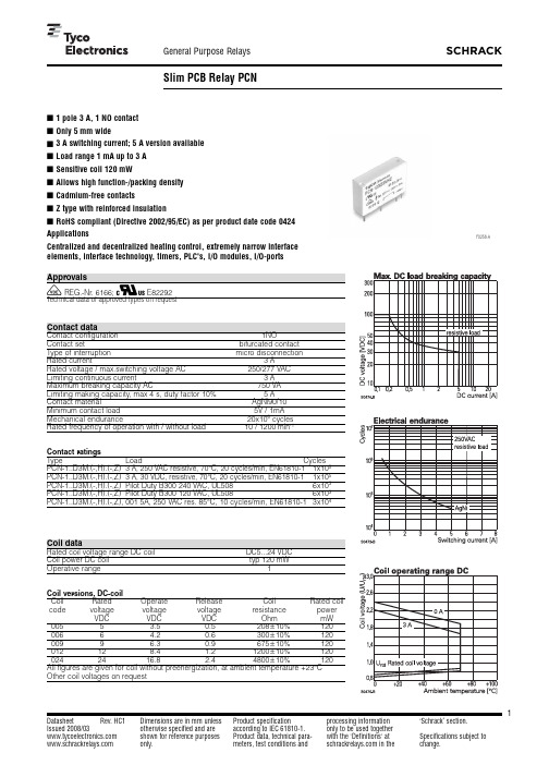
RoHS compliant (Directive 2002/95/EC) as per product date code 0424F0258-A Centralized and decentralized heating control, extremely narrow interfaceelements, interface technology, timers, PLC's, I/O modules, I/O-portsV REG.-Nr. 6166; Z E82292Contact dataContact configuration 1NOContact set bifurcated contactType of interruption micro disconnectionRated current3ARated voltage / max.switching voltage AC 250/277VACLimiting continuous current3AMaximum breaking capacity AC 750VALimiting making capacity, max 4 s, duty factor 10%5AContact material AgNi90/10Minimum contact load 5V / 1mAMechanical endurance20x106cyclesRated frequency of operation with / without load 10 / 1200min-1Contact ratingsType Load CyclesPCN-1..D3M.(-,H).(-,Z)3A, 250VAC resistive, 70°C, 20 cycles/min, EN61810-11x105PCN-1..D3M.(-,H).(-,Z)3A, 30VDC, resistive, 70°C, 20 cycles/min, EN61810-11x105PCN-1..D3M.(-,H).(-,Z)Pilot Duty B300 240VAC, UL508 6x10³PCN-1..D3M.(-,H).(-,Z)Pilot Duty B300 120VAC, UL5086x103PCN-1..D3M.(-,H).(-,Z), 001 5A, 250 VAC res. 85°C, 10 cycles/min, EN61810-1 3x10⁴Coil dataRated coil voltage range DC coil DC5...24VDCCoil power DC coil typ 120mWOperative range 1Coil versions,DC-coilcode voltage voltage voltage resistance powerVDC VDC VDC Ohm mW0055 3.50.5208+10%1200066 4.20.6300+10%1200099 6.30.9675+10%120012128.4 1.21200+10%1200242416.8 2.44800+10%120Other coil voltages on requestPCB layout / terminal assignmentBottom view on solder pinsDimensionsS0471-AAS0471-ABS0472-AInsulationDielectric strength coil-contact circuit3000V rms open contact circuit750V rmsClearance /creepage coil-contact circuit W 3,5 / 3,5mmMaterial group of insulation parts ITracking index of relay base PTI 600Type of insulation coil-contact circuitreinforced open contact circuitfunctional Rated insulation voltage 277V Pollution degree2Rated voltage system277V Overvoltage category as basic insulationIII Overvoltage category as reinforced insulationIIOther dataRoHS - Directive 2002/95/EC compliant as per product date code 0424Flammability class according to UL94V-0Ambient temperature range -30...+70°C Operate- / release time typ. 5/2ms Bounce time NO / NC contact < 1ms Vibration resistance (function) NO / NC contact 10g Shock resistance (function) NO / NC contact 10g Shock resistance (destruction)100g Category of protection RTIII - wash tight Mounting pcb Mounting position any Minimum mounting distance 0mm Resistance to soldering heat wash tight version 260°C / 5s Relay weight 3g Packaging unit 25 / 2000pcs。
ZWS240PAF-24S中文资料(DENSEI-LAMBDA)中文数据手册「EasyDatasheet - 矽搜」

2 year warranty
型号名称
ZWS 100AF-5/
Series Name
Option
Output Power
Active Filter contained
Output Voltage
特征
marking (Low Voltage Directive) Active Filter contained, PFHC type Applicable to peakoutput wattage 120% (12V, 15V, 24V output) Low leakage current 0.5mA max Equipped with Remote ON/OFF control (with-cover type excluded) and output variable voltage 2 year warranty
产品阵容
Model name ZWS50AF ZWS75AF ZWS100AF ZWS150AF
ZWS50AF-5 ZWS50AF-12 ZWS50AF-15 ZWS50AF-24 ZWS75AF-5
ZWS75AF-12 ZWS75AF-15 ZWS75AF-24 ZWS100AF-5 ZWS100AF-12 ZWS100AF-15
芯片中文手册,看全文,戳
ZWS-AF -系列
单路输出50W〜150W
(Low Voltage Directive)
技术指标
1.输 入 电 压 范 围 2.功 率 因 数 3,输 出 电 压 范 围 4.冷 却 5.工 作 环 境
温度 (标准安装)
6.耐 压 7.安 全 标 准 8. CE标志 9. EMI 10.免 疫 11. PFHC 12.函 数
TDR934T.001型综合保护装置技术说明书V100

TDR 934T.001电动机综合保护装置说明书南京钛能电气有限公司目录1.适用范围 (1)2.保护配置 (1)3.测控配置 (2)4.装置特点 (2)5.保护定值 (2)6.应用说明 (4)7.典型接线示意图 (6)注意:产品的型号、功能、配置可能由于软件版本升级有所改变,请注意最新版本资料。
I1.适用范围TDR934T.001型电动机综合保护装置是适用于10kV及以下电压等级高压电动机的综合保护及测控装置。
本装置保护元件可以采用三相TA接入或两相TA接入,装置提供了完善的保护,包括相间短路、反相、断相、过压、失压、过热、过负荷、堵转、启动时间过长、接地、非电量等保护。
本装置测量元件采用专用测量TA,可以采用三相三线接线或三相四线接线。
电动机启动过程闭锁相电流反时限保护。
2.保护配置☑电流速断保护◆动作于跳闸☑过流保护◆动作于跳闸☑两段负序电流保护◆动作于跳闸☑低电压保护◆动作于跳闸☑过电压保护◆动作于跳闸☑过负荷保护◆告警☑堵转保护◆告警或动作于跳闸☑启动时间过长保护◆告警或动作于跳闸☑两段过热保护◆I段告警◆II段告警或动作于跳闸☑过热禁止再启动保护☑零序过流保护◆告警或动作于跳闸☑零序过压保护◆告警或动作于跳闸☑相电流反时限保护◆I段、II段强反时限曲线动作于跳闸◆I段、II段极度反时限曲线动作于跳闸☑零序电流反时限保护◆强反时限曲线动作于跳闸◆极度反时限曲线动作于跳闸☑非电量保护◆告警或动作于跳闸☑TV断线监视☑开关位置监视☑告警、事故事件记录1☑故障录波和分析软件3.测控配置☑23路开入量采集电路,64路遥信信号及相关的SOE信号☑12路模拟量采集(Ua、Ia、Ub、Ib、Uc、Ic、IA、IB、IC、备用、3I0、3U0)☑遥控断路器的分合闸☑电压、电流、功率、功率因数、频率等模拟量的遥测4.装置特点☑保护功能齐全,复合电压闭锁元件和方向元件可选择投入或退出;☑各保护功能均可选择投入或退出;☑带测量和控制功能,测量TA和保护TA独立;☑测量元件支持三相三线接线或三相四线接线;☑可存贮多达16套保护定值,定值切换可在线实现。
DS-AT1000S 234系列存储系统简介说明书

IntroductionDS-AT1000S/234 series storage system is a storageproduct with huge capacity and high-density design. A3U chassis provides up to 234 TB capacity. Compared togeneral storage product, DS-AT1000S reduces the totalcost at up to 40%. iRAID technology realizes anintensive management for storage space and data, andprotects the data security from substructure. Hierarchical storage technology improves data search performance by at least 10 times. Periodic HDD replacement guarantees the product availability.Key FeatureHuge Capacity and High Density● A 3U chassis provides up to 234 TB capacity●High-density design reduces the installation space requirement and transportation costLow consumptionFor 18 TB enterprise HDD, lower consumption for each terabyte at 50%Security and Reliability●iRAID technology and N + M redundant mechanism allow up to 2 error HDDs in a single RAID●HDD encryption technology protects data security by only allowing Hikvision device to read the data in HDD Maintenance-Free●Rebuild fault HDD on-demand●HDD periodic automatic replacementStream Data Management Structure of High PerformanceBased on the bottom layer management structure of the stream media, it solves the problem that the damaged file system will lead to file unreadability or loss and ensures no file fragments will be produced during overwriting Direct Storage of Mixed Stream●Supports mixed storage of video stream and SMART stream●Supports camera access through protocols including RTSP, ONVIF, PSIA, etc.iRAIDErasure encoding and iRAID technologies ensure data integrity even when 2 HDDs in a single RAID are error. If the number of error HDD exceeds redundant limit, other HDDs can still be read and writtenAbundant Application●Continuous recording, manual recording, and alarm recording●Provides Automatic Network Replenishment (ANR) feature to ensure data integrity when network isabnormal●Supports data backup to ensure data securityUser-Friendly Operation and Maintenance●Supports one-key configuration to improve system configuration efficiency●Raises device maintenance efficiency via abundant alarm management methods, like alarm via indicators,mobile phone messages, and emails.Specification Model DS-AT1000S/234Performance Video (2 Mbps stream + rebuilding)256-chController Processor64-bit multi-core processor Cache12 GB, extendable to 32 GBStorage HDD slot16 (the device is packaged with 13 HDDs) Interface SATACapacity Up to 18 TB per HDDRAID iRAID, RAID5, RAID6Disk Disk detection pre-alarm and repair Logical volume Recording volume managementRecording Recording type Continuous recording, manual recording, and alarm recordingVideo protection Video lock, video loss alarmSearch and downloadLog in storage system to search, play, and download videos. Supportsearching videos by time, and event typeMaintenance and Management Management method GUI based on web, serial port CLI, platform Alarm method Audio, indicator, GUINetwork Protocol RTSP, ONVIF, HKSDKExternal interface Data network interface3, 1000Mbps Ethernet interfaceManagement networkinterface1, 1000Mbps Ethernet interfaceSAS interface2COM interface1, RS-232USB interface2, USB 3.0HDMI interface2VGA interface Supported (VGA and RS-232 interface cannot be used at the same time)General Power supply Redundant power supplyPower consumption(with HDDs)≤ 255 WEnvironmenttemperature●Working: 5 °C to 40 °C (41 °F to 104 °F)●Storing: -20 °C to +70 °C (-4 °F to +158 °F) Environment humidity●Working: 20% to 80% RH (non-condensing/frozen)●Storing: 5% to 90% RH (non-condensing/frozen) Dimensions (W × D × H)440 ×132 × 495 mm (14.3 ×5.2 × 19.5 in)Weight (without HDDs)≤ 20 kg (44.1 lb)Physical Interface8123910764115No. NameNo. Name 1 Power module 1 7 Reset button 2 HDMI inteface 1 8 Alarm interface 3 USB interface9 Power module 2 4 Data network interface 1 to 3 10 HDMI interface 2 5 Management network interface 11 RS-232 interface 6SAS interfaceAvailable Model DS -AT1000S/234。
PMC-24 产品说明书

PARTS IN PLASTIC BAG (PACKED INSIDE WINCH BOX )Item A B C D E F G H I J K L M N V W X Y Product Code #4255040550300522803235283407503526432004320052450028024204132041628025320193200672621032020Qty 614111111122211111Description 1/4-20 keps nuts 10-24 keps nut 1/4-20x3/4 carriage bolts Plate washer#10 lock washer10-32 Hex nut 10-32x1/2 self-threading screw 1/4x2 split pin 1/4x1-1/2 split pin #10 I.D. x7/16 O.D. washer 1-1/2 B clamps (2 square holes)1-3/4 clamps Links 1-1/2 B clamp modified (2 round holes)1/4-20 insert nut 1/4-20x2 hex head (HH) bolt Pulley end assembly 5/16 star washerPARTS PACKED IN POST BOXItem Q R S U 1 ProductCode #27806927808278102781227860900003Qty 111111Description 1-1/2”x74” Post (top section, 3 holes in end)1-1/2”x74” Post (center section with splice)1-3/4”x72” Post (bottom section)1-3/4”x28-1/4” House tube 2”x30” Ground socket Ground socket hardwarePARTS PACKED IN WINCH /HARDWARE BOXItem AA BB CC DD ProductCode #728000728205728040900019Qty 1111DescriptionWinch (assembled)Safety clamp (assembled)Winch cable Post and winch hardware (plastic bag)Covered by U.S. Pat. Nos: RE25,878; 3,367,632; 3,410,248;3,426,732;3,496,913; 3,563,205; D-221,090; 3,643,631; 3,986,480.BJN(reduced)CLAMP ASSEMBLY(reduced)IW [2”]X YV Form 650-2004Parts list continues on Page 2ACDEGH(reduced)Parts list continued from Page 1Parts packed in house box and winch hardware boxThis house has an opening through the center which takes a 1-3/4”O.D. tube (house tube). This tube is clamped to the top of the ceiling and to the bottom of the lower floor. The house and tube slide up and down the pole and is raised and lowered by the cable over a pulley at the top of the pole. See drawing.Page 2PMC-24 Instructions232425222130PARTS IN SMALL PLASTIC BAGItem 2122232425Product Code #3526142550352523525935288Qty 124121212Description6-32x5/16 pan head machine screws (PHMS)1/4-20 keps nuts 6-32 keps nuts#6 Sheet metal screws (SMS)6-32 acorn nutsPARTS IN PLASTIC BAGItem 3031Product Code #2730043101Qty22Description Kit wrench U bolts HOUSE PARTS PACKED IN THIS BOXItem 11a 2345678910111214Product Code #82740082740182741082742265649250408274062803427415656489250658274282624135286Qty 31616242411242412412DescriptionFloor assemblyBottom floor assembly Roof sections Ceilings6-32x25-1/2 tie rods DoorsCompartment dividersCable tube FinialDoor rods Winter door stops (in two plastic bags)Perch assembly Floor traysFlat C nuts (pre-installed on roof and ceiling)Pulley Cable (CC)Clamp and CeilingCable Tube (7)Splice 1-3/4” O.D.House Tube (U)Winch (AA)ClampPost BottomSection (S)Post Center Section (R)Post Top Section (Q)Safety Clamp (BB)17-1/2”14Page 3 PMC-24 InstructionsAssembly Instructions Read all instructions before starting assembly.This will acquaint you with each step required.3. Place bottom floor assembly [1a] on cardboard box with mounting plate between carton flaps in order that floor may be held level. Position so that about 6”extends over end of carton (for easy access to under-side of floor at Step 7). Install six door rods [9] in two holes at top of each doorway on bottom floor (do not install doors yet).4.Nest second floor. (Note: Riveted seams on this floor should be over seams on first floor.)Locate in proper position over dividers below by inserting the two round top tabs on each divider into the round holes in floor. BE SURE that round tabs are to the inside of each divider front on second floor. Door rods [9] for second floor can now be added.2. Repeat this procedure on other three floors, but do not stack floors together at this point.1. Start with bottom floor.(Note that ceiling [3] and bottom floor have mounting plate rivet-ed in place.) Place one compartment divider [6] on floor assembly [1] as shown. Ventilation holes are up.The three square tabs go into “D” holes in floor. Bend tabs against straight side of “D” on underside of floor. Place another divider [6] adjacent to first and slide flange near cen-ter into slot provided. Bend tabs to hold in place. Repeat with balance of dividers for bottomfloor. Slide last divider into slot and flange from above, interlocking all pieces around center. Wipe protective oily coating from all martin house parts surfaces prior to assembly.Page 4PMC-24 Instructions5.Proceed with third and fourth floors using samesteps as used on page 3.6. Ceiling [3] is installed over top floor in same manner.Mounting plate goes up. MAKE SURE flange onmounting plate faces in same direction as mountingplate on bottom floor.7.Install one 6-32 keps nut [23] on each of the six tierods [4]. Use kit wrench [30] after starting. On ceilinglocate six round holes between each set of “D” holes,about two inches from edge. These holes are for tierods. Insert tie rods [4] into round holes over edge ofcarton. Use nail to align holes in assembly if required.Guide rod through hole in top floor, then rotate rodslowly and it will drop through assembly. Thread 6-32keps nut [23] onto lower end of tie rod on underside ofbottom floor. Do not tighten completely at this time.Slide house to other end of carton and install tie rodsin the two holes now exposed. Rotate house and installfinal two tie rods. Assembly must be handled withcare until all tie rods are in place.Nuts can now betightened until snug.Page 5PMC-24 Instructions8. Turn house on side and inspect round end tabs and door rods for correct location. Readjust if required.9. Hook doors [5] over door rods [9]. Do not force. Doors should hinge freely and snap into door clips on floor.10. Turn house back to horizontal position, rotate until notch in mounting plate is on lower side. Insert cable tube [7] from either end through hole in center of house and drop into notch. Flange on ends of tube should be on outside of mounting plates. Seam ofcable tube is to be towards center of house.11. Assemble two U-bolts [31] with mounting plates on ceil-ing and bottom floor, using four 1/4-20 keps nuts [22] as shown.12.Cable is attached at point shown to mounting plate on ceiling using 10-32x1/2 self-threading screw [G]. Insert screw from inside mounting plate. Place plate washer [D]over screw with bevel out. Loop end of cable [CC] is now placed over screw and plate washer [D]. Add #10 washer [J], #10 lock washer [E], 10-32 hex nut [F] and tighten securely with cable in perpendicular position to ceiling.31Page 6PMC-24 InstructionsExploded viewNumbers/lettersrefer to partsidentificationnumbers/lettersmentioned inthe instructions.Page 7 PMC-24 Instructions13. Install house tube [U] through house and U-bolts. Tighten nuts with slotted end of tubetwo inches above ceiling and with slots at 90° to cable hole in ceiling as shown. This assemblyshould be quite tight but care must be taken not to distort house tube. Make sure that 1-1/2”x74” post center section [R] slips into house tube freely. The notch in house tube, wheninstallation is complete, engages with a pin below pulley on 1-1/2”x74” post top section [Q] andlimits the height to its proper position and prevents the house from turning on pole.14. Starting with two roof sections [2] and using twelve6-32x5/16 PHMS [21] and twelve 6-32 acorn nuts [25],attach six roof sections to each other as shown. Headof screw should be on outside and acorn nut on insideof smaller section. Do not tighten at this time.15. Place finial [8] over roof peak and using six #6 SMS[24] fasten in place. Tighten all screws on roof. Roof isnot attached to house until Step P9.Page 8PMC-24 InstructionsGS 1.Assemble tube clamps [2] as shown. Start 1/4-20 keps nuts [3] but do not tighten. Place assembly over slotted end of MPS galvanized tube [1] and tighten nuts until snug. GS 2. Insert 1/4-20x2-1/4 HH bolt [5] in hole near bottom of 2”O.D.x30” long galvanized tube [1]. Place 1/4-20 keps nut [3]on end of 1/4-20x2-1/4 HH bolt [5] and tighten.GS 3.Slide post bottom section (S) into ground socket 24” and tighten 1/4-20 keps nuts [3] until post section is secure.GS 4.Dig hole 8” diameter and 34” deep. Put coarse gravel in bottom of hole until top of ground socket is to ground level [30”]. GS 5. Place crumpled newspaper inside lower end of socket to prevent concrete from sealing post. This will allow any water to drain from inside post.GS 6.Place ground socket/post section assembly in center of hole. Fill with concrete mix to just below slots in upper end of the socket [approx. 4” from ground surface]. This will require approximately 80 to 90 pounds of mix. Use guy wires or rope to hold assembly in vertical position while concrete sets. BE SURE to allow sufficient clearance above concrete to use wrench on clamp.GS 7.After concrete has hardened, loosen clamps and slide post section to bottom of socket. Re-tighten clamps securely.MPS Ground Socket InstallationGround socket allows the pole and house to be moved to another locationwithout losing the post bottom section.Please use “Product Code #” when ordering replacement partsBottom postsection [S]HARDWARE PACKED IN POST BOX WITH MPSItem 12345Product Code #2786020413425503005332003Qty12321Description 2”O.D.x30” long galvanized tube Tube clamps 1/4-20 keps nuts 1/4-20x1-1/4 carriage bolts 1/4-20x2-1/4 hex head (HH) boltPage 9PMC-24 Instructions P 1. Assemble clamps as shown using 1/4-20 keps nuts [A], 1/4-20x3/4 carriage bolts [C], “B” clamps [K], 1-3/4 clamps [L], and links [M]. Place 1-3/4 clamps [L] over top end of post bottom sec-tion [S]. Top is end with four rings. Tighten nuts on 1-3/4 clamps [L] securely. Leave “B” clamp [K] nuts loose.P 2. As safety clamp [BB] will be used in assembly, adjust at this time. Slide clamp over either end of center post section [R]. Adjust by tightening nut with handle against post until snug. Handle is down when nut is adjusted and to right side of pole. Raise and lower handle a few time.P 3.If handle is not locking tight,turn nut 1/2 turn tighter; if tooP 6. Slip center post section [R] into top post section [Q] as shown. Post should be assembled on a level surface such as a sidewalk or lawn. Turn post sections until holes in splice are in accurate alignment through post; then tap 1/4x1-1/2 split pin [I] through post until flush.NOTE: This pre-alignment is essential and pin should drive through assembly with ease.Post Installation InstructionsPage 10PMC-24 InstructionsP 7. With post assembly supported in a horizontal position, slidemartin house over post from lower end. Slip safety clamp over postand lock into position 18-1/2 inches from bottom end of post tolower edge of clamp. Note:In order to support post, it is suggest-ed that two chairs be used.The safety clamp was designed for the user’s protection. Alwayskeep the safety clamp above your head when making installa-tion, raising or lowering of house.P 8.Thread cable over pulley at top end of post. Insert throughcable tube and from bottom of house pull cable until slack hasbeen taken up. Make sure cable is not twisted above house.P 9. Slip roof over top end of post and fasten to house using six #6sheet metal screws [24]. Note that flange on roof is located over flatC nut [14] on ceiling tab and screw is installed at an upward angle.Page 11PMC-24 Instructions P 10. Place 5/16 star washer [Y] over threadedstud above pulley, then add perch assembly[11]. Fasten in place using 10-24 keps nut [B].(Refer to exploded view on page 6.)P 11. House is ready to install in bottom post section [S]. Itis best to use two people on this phase of the installa-tion.Pick the house and post assembly up and with post invertical position insert into the bottom post. Allow assemblyto rest on safety clamp (installed at Step P 7) and tightennuts on “B” clamp [K].NATURE HOUSE MARTIN SAFETY SYSTEMSARE THE ONLY MARTIN HOUSES OFFEREDWITH SAFETY FEATURES FOR THE USER’SPROTECTION.P 12.Release safety clamp and raise clamp and house man-ually a few inches so that winch can be installed. Re-lockclamp.Winch [AA] is attached to center post section [R] just above“B” clamp [K]. Use 1-1/2 “B” clamp modified [N] and two1/4-20 keps nuts [A].Note: Label on winch case cover should be to the right.Align winch drum under cable hole in bottom of house andwith pulley. (Cable will be parallel to post.) Again, checkcable to make sure it is free.Winch DrumPage 12PMC-24 Instructions P 13. Loosen wing nut on winch drum, thread cable endthrough either hole in drum face from inside of drum. Windcable around stud, between plate washer and round washer,and tighten wing nut. Cable end should be at least 1/2”beyond washers. Slack cable can be wound onto drum byturning winch handle in clockwise direction. DO NOT RAISEHOUSE YET!Two safety features are designed into the winch. First, abrake mechanism to carry the weight of the house and, sec-ond, a ratchet and pawl to hold weight of house. The pawllever is on upper left of winch. In operation, it is necessaryto disengage pawl to lower house. To adjust brake, tightenspring tension by turning wing nut on lower right in clock-wise direction until brake will hold weight of house. Raisehouse an inch or two and release pawl. If house slips down,tighten brake further.Floor trays [12] can now be placed in house. Flanges on sides of floortrays go down.Use winter door stops [10] to close house during winter months. To install door stops, remove door, place door stop upside down on a flat surface and press door onto door stop then rehang door.To reduce tampering with installation, pawl and winch case can be fastened together throughholes provided. If this is desired, use bolt and nut, wire or padlock for this purpose.For replacement parts or accessories call toll-free 877-833-2478 or 800-255-2692Nature House products byERV A TOOL & MFG CO INC3100 W GRAND A VE, CHICAGO IL 60622-4324Phone800-342-3782E-mail<**********************>Fax800-342-3781Nature House — bringing the benefits of nature to your house。
亚特诺PDG24P0150P3DJ产品说明书

Eaton PDG24P0150P3DJEaton Power Defense molded case circuit breaker, Globally Rated, Frame 2, Four-pole (100% N), 150A, 100kA/480V, PXR25 LSIG w/ Modbus RTU, CAM Link and Relays, Standard Line and LoadGeneral specificationsEaton Power Defense molded case circuit breakerPDG24P0150P3DJ 78667934362388.9 mm 152.4 mm 139.5 mm 2.46 kg Eaton Selling Policy 25-000, one (1) year from the date of installation of theProduct or eighteen (18) months from thedate of shipment of the Product,whichever occurs first.RoHS Compliant IEC 60947-2CCC MarkedProduct NameCatalog Number UPCProduct Length/Depth Product Height Product Width Product Weight WarrantyCompliancesCertificationsModbus / Relays / CAM100 kAIC at 480 Vac2600150 AFour-pole (100% N)600 VPD2 Global22 kAIC Icu @125 Vdc22 kAIC Icu @250 Vdc10 kAIC Icu/ 5 kAIC Ics/ 21 kAIC Icm @690V (IEC)100 kAIC @480V (UL)35/25 kAIC Icu/ 18/13 kAIC Ics @525V South Africa (IEC) 100 kAIC Icu/ 65 kAIC Ics/ 220 kAIC Icm @440V (IEC)200 kAIC Icu/ 150 kAIC Ics/ 440 kAIC Icm @240V (IEC)85 kAIC Icu/ 40 kAIC Ics/ 187 kAIC Icm @480V Brazil (IEC) 200 kAIC @240V (UL)35/25 kAIC @600V (UL/CSA)100 kAIC Icu/ 70 kAIC Ics/ 220 kAIC Icm @380-415V (IEC) 25 kAIC @600V (UL/CSA)Class AComplete breakerStandard Line and Load600 Vac Eaton Power Defense MCCB PDG24P0150P3DJ 3D drawingPower Xpert Protection Manager x64Consulting application guide - molded case circuit breakersPower Xpert Protection Manager x32Power Defense molded case circuit breaker selection posterPower Defense brochurePower Defense technical selling bookletPower Defense molded case circuit breakers - Frame 2 product aidPower Xpert Release trip units for Power Defense molded case circuit breakersMolded case circuit breakers catalogPDG2 CB reportPDG4 CB reportPDG4 CCC certificationEU Declaration of Conformity - Power Defense molded case circuit breakersPower Defense Frame 2 screw terminal_end cap kit, 225A, 3 pole instructions - IL012258EN H01Power Defense Frame 2 terminal kit - PDG2X3(2)(4)TA225RF instructions - IL012245EN H01Power Defense Frame 2 shunt trip UVR instructions - IL012130EN Power Defense Frame 2 tunnel terminal (aluminum), 100A, 4 pole instructions - IL012237EN H04Power Defense Frame 1-2-3-4 IP door barrier assembly instructions - IL012278ENPower Defense Frame 2 terminal kit - PDG2X3(2)(4)TA150RF instructions - IL012244EN H01Power Defense Frame 2 global terminal shield, 4 pole - IL012330EN Power Defense Frame 2 box terminal (steel), 100A, 4 pole instructions - IL012234EN H04Power Defense Frame 2/3/4/5/6 voltage neutral sensor module wiring instructions – IL012316ENSpecial featuresInterrupt ratingFrameRated operation voltage (Ue) at AC - max Amperage RatingNumber of polesVoltage rating - maxCircuit breaker typeInterrupt rating rangeClassCircuit breaker frame typeTerminalsVoltage rating 3D CAD drawing package Application notesBrochuresCatalogsCertification reports Installation instructions100% neutral protection PXR 25 LSIGModbus RTU and CAM Link Power Defense Frame 2 tunnel terminal (aluminum), 50A, 4 pole instructions - IL012236EN H04Power Defense Frame 1 IEC and Frame 2 Rotary Mechanism with NFPA Handle Attachment Instructions (IL012260EN).pdfPower Defense Frame 2 locking devices and handle block instructions - IL012149ENPower Defense Frame 2 multi wire connector kit -PDG2X3(2)(4)TA2256W instructions - IL012242EN H01Power Defense Frame 2 PDG2 and PDC(E)9 breaker instructions -IL012106ENPower Defense Frame 2 Bell Alarm Switch Instructions (IL012154EN).pdf Power Defense Frame 2 clamp terminal (steel), 20A, 4 pole instructions - IL012246EN H04Power Defense Frame 2 box terminal (aluminum), 225A, 4 pole instructions - IL012235EN H04Power Defense Frame 2 tunnel terminal (aluminum), 150A, 4 pole instructions - IL012238EN H04Power Defense Frame 2 tunnel terminal kits - PDG2X1TA225K instructions- IL012239EN H01Power Defense Frame 2 multi wire connector kit -PDG2X3(2)(4)TA2253W instructions - IL012243EN H01Power Defense Frame 2 TMTU Aux, Alarm, ST and UVR Animated Instructions.rhPower Defense Frame 2 Bell Alarm with PXR Animated Instructions.pdf.rh Power Defense Frame 2 withTMTU, Shunt Trip_UVR Animated Instructions.rhPower Defense Frame 2 Variable Depth Rotary Handle Mechanism Installation How-To VideoPower Defense Frame 2 Direct Rotary Handle Mechanism Installation How-To VideoPower Defense Frame 3 Variable Depth Rotary Handle Mechanism Installation How-To VideoPower Defense Frame 2 Aux, Alarm, Shunt Trip, and UVR How-To Video Power Defense Frame 5 Trip Unit How-To VideoPower Defense BreakersPower Defense Frame 6 Trip Unit How-To VideoEaton Power Defense for superior arc flash safetyPower Defense molded case circuit breakersEaton Specification Sheet - PDG24P0150P3DJProtectionTrip TypeCommunicationInstallation videosMultimediaSpecifications and datasheetsEaton Corporation plc Eaton House30 Pembroke Road Dublin 4, Ireland © 2023 Eaton. All Rights Reserved. Eaton is a registered trademark.All other trademarks areproperty of their respectiveowners./socialmediaPower Defense time current curve Frame 2 - PD2Molded case and low-voltage power circuit breaker health Single and double break MCCB performance revisited Making a better machineIntelligent power starts with accurate, actionable data Intelligent circuit protection yields space savings Safer by design: arc energy reduction techniques Molded case and low-voltage breaker healthTime/current curvesWhite papers。
AT45DB014D中文说明

翻译:王兵洋
2017-7-10
1
1、大致描述
AT45DB041D 是 2.5V/2.7V 串行 FLASH 存储器,能够存储声音、图片、编程代码等大容量数据。它支持高速串行接 口,适用于要求高速数据操作的应用。它的 SPI 接口速率提高到了 66 MHz,4,325,376 bits 的数据由 2048 页(每页 256/264 bytes)数据组成。缓冲区允许在主存正在被重写的过程中接收(连续)数据,自带的读—修改—写控制单元能让修改 EEPROM 的冲突很方便的受到控制。有别于传统的 FLASH 存储器使用众多的功能线、地址线来存取数据, AT45DB041D 采用了快速串行接口来实现数据存取,明显的减少了管脚数目和方便了硬件制板,增加了系统可靠性, 减少了开关噪声,并且缩小了封装尺寸。能够在高密度、低管脚数、低压和低功耗的商业和工业应用中得到最优化的 发挥。 AT45DB041D 不需要很高的编程电压,只需要 2.7/2.5V——3.6V 单供电即可完成在编程操作。AT45DB041D 由 CS 引 脚来使能,芯片的数据操作由三线(SI、SO、SCK)组成的接口即可完成。 另外它的所有编程和擦除周期都是自同步的。
翻译:王兵洋
2017-7-10
3
5、芯片操作
芯片的各操作指令都是由主处理器发出,Table15-1 到 Table15-7 是操作代码的列表。一个有效的命令是 在 CS 有效,并且要紧随有效的 8 位操作码和合适的缓存或者主存中的地址。所有的串行操作都是高位 在前(MSB)。 标准的缓存区(264 bytes)是由 BFA8——BFA0 这 9 位地址数据来描述。主存地址是由 PA8——PA0 和 BA8——BA0 来指定,其中 PA8——PA0 这 9 位用来指定页地址,而 BA8——BA0 是这 9 位用来指 定页内数据存放的地址。 二进制页大小(256 bytes),缓存区的地址是由传统的 BFA7——BFA0 这 8 位来指定地址,主存中的地 址是由 A16——A0 来指定,其中 A16——A8 这 9 位用来指定页地址,而 A7——A0 是这 8 位用来指定 页内数据存放的地址。
D3+中文手册

Room 1701 Kerry Everbright City Tower 2, No.218 Tianmu Road West, Shanghai, P. R. China 200070Tel: (86 21) 6317 2505, 6317 2606; Fax: (86 21) 6317 1583; E-mail: master@ DEPOLOX 3 PLUS余氯分析仪上海中之良实业有限公司二○○一年三月Room 1701 Kerry Everbright City Tower 2, No.218 Tianmu Road West, Shanghai, P. R. China 200070Tel: (86 21) 6317 2505, 6317 2606; Fax: (86 21) 6317 1583; E-mail: master@ 第一节技术数据1.1 D3+电工学特性1.电源: 230V± 10%,50/60Hz,14VA。
保险F规格:T160mA,50×20mm2.CL2测量范围:0.2/0.5/1.00/2.00/5/00/10.00/20.0mg/lPH 测量范围:PH4.0~PH10.00, PH0~PH14(随选)氟化物测量范围: 0.2~2.00mg/l (随选)3.测量信号输入:氯、PH、氟化物各一个输入点(探头),对地电工学绝缘特性达50V。
4.mA输出:氯、PH、氟化物的测量各有一个mA输出点,对地电工学绝缘性50V,最大1000Ω负载。
5.开关量输出:氯、PH、氟化物各有两个可自由配置的报警触点,电子学对地绝缘500V。
6.继电器额定值触点: 5A,16HP,125,250AC或5A,30V DC 30W(最大值),用抑制二极管消除干扰。
7.1×数字输入:对于样水或循环泵监测以干式触点方式输入,非绝缘。
8.环境温度:0~50℃1.2 自由氯测量单元1.测量室:恒电势三电极测量室。
AT24C1024 中文说明书

AT24C10242线串行EEPROM特性低电压操作:2.7(Vcc=2.7V to 5.5V)内部组织:131,072*8位=1M2线串行接口施密特触发器,噪声抑制滤波输入双向数据传输协议时钟速率:400kHz(2.7V)和1MHz(5V)硬件写保护引脚和软件数据保护256字节页写模式(允许部分页面写入)随机和顺序读写模式自定义写周期(5ms)高可靠性:耐久力:写周期/页100,000次数据保留:40年8引脚PDIP,8引脚有铅SOIC封装,8引脚无铅阵列和8引脚球状dBGA封装描述AT24C1024提供1,048,567位的串行可电擦除和可编程只读存储器(EEPROM),它的每8位组成一个字节,共131,072个字节。
该设备的级联功能允许多达2个设备共亨同一条2-线总线。
该设备适合用于许多工业和商业,应用必要的低功耗和低电压的操作。
该器件可提供节省空间的8引脚PDIP,8引脚有铅SOIC封装,8引脚无铅阵列和8引脚球状dBGA封装。
另外,这一系列产品允许在2.7V(2.7V~5.5V)下工作。
绝对最大额定值:工作温度:-55~+125存储温度:-65~+150任何引脚的对地电压:-1.0V~+7.0V最大工作电压:6.25V直流输出电流:5.0mA注意:强制高出“绝对最大额定值”可能导致设备的永久损坏。
设备的压力等级和功能操作只有在这些或超出本规范所标明的其他任何条件下是不允许的。
长时间工作在绝对最大额定值的条件下可能影响设备的可靠性。
引脚描述::引脚描述串行时钟(SCL):SCL的输入是在时钟的上升沿数据进入每个EEPROM设备和下降沿数据输出每个设备。
串行数据(SDA):SDA引脚是双向串行数据传输的。
这个引脚是漏极输出的,可以与其它的漏极开路或集电极开路的设备线或。
器件/页地址(A1):A1引脚是设备的输入地址,它能够通过导线与不兼容的设备AT24C128/256/512连接。
当A1通过硬件连接时,2个以上的1024K设备可以在同一条系统总路线上寻址(下面会详细谈论设备的地址选择)。
变压器单元D3及D类型商品简介说明书

D3RETROFIT TERMINAL UNITSDRound Duct External Retrofit Terminal UnitConver t existing constant volume systems or old "system power ed" mechanical r egulator ter minals to ener gy efficient variable volume operation.• Available in 10 sizes to suit and install simply in ound ductwork. 0 – 4050 cfm (0 – 1911 l/s).• Va ious configu ations custom fab icated to suit individual applications.• Pressure dependent or independent airflow control.• Diamond Flow multi-point aver aging flow sensor on pr essur e independent models.• Digital, electric, analog electronic or pneumatic control.Model 36VRR See page D5Rectangular Slide-in Retrofit Terminal UnitConvert existing constant volume systems to energy efficientvariable volume operation.• Available in 15 valve sizes to handle a large range of air volumes. 0 – 15000 cfm (0 – 7079 l/s).• Custom fab icated to suit any duct size f om 5" x 5" (127 x 127) up to 52" x 26" (1321 x 660).• Diamond Flow multi-point averaging sensor.• Pressure independent airflow control.• Digital, analog electronic or pneumatic control.Model 36VRSSee Page D10GENERAL PRODUCT OVERVIEWInternal Retrofit Terminal UnitsDesigned to replace the mechanical regulators in old systempower ed ter minal units in or der to substantially lower the ope r ational static p r essu r e r equi r ement. The ai r valves include a damper , flow sensor and actuator and make use of state-of-the-art controls in order to reduce operating cost.• Custom built on a specific project basis.• Variable or constant volume pressure independent airflow control.• Diamond Flow multi-point averaging flow sensor.• Models available to r etr ofit most br and name mechanical regulator design terminal units.• Digital, analog electronic or pneumatic control.Model 36VRTR Contact your Nailor Sales Rep.Retrofit Terminal Units• Convert Constant Air Volume Systems to Variable Air Volume.• Convert Constant Volume Dual Duct Systems to Variable Air Volume.• Convert Multizone Systems to Variable Air Volume.• Convert Mechanical Constant Volume Regulators to Low Pressure Digital, Analog Electronic or Pneumatic Controls.Nailor manufactures a range of standard and custom design retrofit terminal units for all applications.Model 36VRRModel 36VRS Model 36VRTRModel 36VRSD4R E T R O F I T T E R M I N A L U N I T SConstant Volume Reheat SystemCold ai f om the cent al station is dist ibuted th ough the existing main t unk and b anch ducts. The Model 36VRS Retrofit Terminals will convert the constant volume system to pressure independent variable air volume operation.Each 36VRS te r minal is signaled by a di r ect acting the r mostat. The p r essu r e independent minimum ai r flow is set at a thermostat output pressure of 8 psi or less, while the maximum is set at 13 psi or greater.The existing reheat coil in each zone is actuated on a fall in room temperature, as the thermostat output decreases from 8 to 3 psi.The fan capacity must be reduced since the total air volume is reduced.Multizone SystemHot or cold air from the central station multizone air handler is distributed through the existing zone system. The Series 36VR Retrofit Terminals will convert the multizone system to variable air volume operation.The zone damper s in the centr al station air handler ar e made with two-position actuator s; each zone is fully open, either heating or cooling. There is no mixing. (Controls may be selected for an outdoor thermostat, a manual selector or changeover signal.)A dual function ther mostat in each zone is dir ect acting for cooling, r ever se acting for heating. In r esponse to the r oom temper atur e, the ther mostat r esets the velocity contr oller for pressure independent control of the Series 36VR .The fan capacity may be reduced since the total air volume is reduced.Some Typical Applications for the Model Series 36VR Retrofit Terminal UnitsDual Duct SystemHot and cold air from the central station is distributed through the existing supply ducts and terminals. The Series 36VR Retrofit Terminals will convert the constant volume system to variable air volume pressure independent operation.Remove the mechanical constant volume regulator from the existing ter minal, while a Model 36VRS is installed in the dischar ge box or duct. A dir ect acting ther mostat contr ols both the 36VRS unit and the modulating tandem damper in the existing box. On a rise in room temperature, the 36VRS reduces the hot airflow. At the minimum setting, the damper in the existing terminal begins to modulate, and mixing occurs. A fur ther temper atur e r ise incr eases the cold air flow to the maximum.The fan capacity may be r educed down since the total air volume is reduced.D5RETROFIT TERMINAL UNITSDModel 36VRR is designed for r ound ductwor k r etr ofit application. Ter minals ar e available in 10 sizes and ar e nominally undersized to ensure a good fit.Easy, low-cost installation into existing ductwor k. The installer cuts out a section in the round duct and replaces the duct section with the conversion unit.STANDARD FEATURES:• Casing 22 ga. (0.86), corrosion-resistant steel with stiffening beads. Sizes 14 and 16 are 20 ga. (1.0).• Blade: Two layers of 22 ga. (0.86), cor osion-r esistant steel laminated together (equivalent to 16 gauge) with across-linked polyurethane peripheral gasket for tight shut-off, 90° rotation, CW to close. Damper leakage is less than 1% of terminal rated airflow 3” w.g. (750 Pa) as tested in accordance with ANSI/ASHRAE Standard 130.• Bearing: Self-lubricating oilite bronze and less than 2% at 6” w.g. (1500 Pa).• Drive Shaft/Axles: 1/2” (13) diameter plated steel, double-bolted to blades. Indicator mark on the end of the shaft to show damper position.• Full electrical controls enclosure for factory mounted DDC and analog electronic controls.• Multi-point aver aging ‘Diamond Flow’ sensor . Aluminum constr uction. Gauge taps ar e pr ovided for field balancing when controls are factory mounted.• Right-hand contr ol location is standar d (as shown). Left-hand is optional.Options:• FMI Removable Flow Sensor• Available in Type 304 and 316 stainless steel construction for laboratory/fume hood exhaust applications.• Controls enclosure for field mounted controls.• 24 volt control transformer. • Toggle disconnect switch.• Pneumatic o Analog Elect onic P essu e Independent controls by Nailor. Factory mounted and calibrated.• Digital contr ols by BMS Contr actor. Factor y mounted byNailor.FACTORY MOUNTED CONTROLSD6R E T R O F I T T E R M I N A L U N I T S4GEQOOGPFGF #KTƀQY 4CPIGU (QT /QFGN 844 4QWPF 4GVTQſV 6GTOKPCN 7PKVUThe r ecommended ai r flow r anges below a r e fo r Round Duct Ret ofit Te minal Units with p essu e independent cont ols and ar e pr esented as r anges for total and contr oller specific minimum and maximum airflow. Airflow ranges are based upon maintaining reasonable sound levels and controller limits using Nailor’s Diamond Flow Sensor as the air flow measur ing device. For a given unit size, the minimum, auxiliar y minimum (wher e applicable) and the maximum flow setting must be within the r ange limits to ensur e pressure independent operation, accuracy and repeatability. Minimum airflow limits are based upon .02" w.g. (5 Pa) differential p r essu r e signal f r om Diamond Flow Senso r on analog/digital contr ols and .03" (7.5) for pneumatic contr ollers. This is a realistic low limit for many transducers used in the digital controls industry. Check with your controls supplier for minimum limits. Setting airflow minimums lower , may cause hunting and failur e to meet minimum ventilation requirements. Factory settings will therefore not be made outside these r anges. A minimum setting of zer o (shut-off) is also available. Where an auxiliary setting is specified, the value must be greater than the minimum setting.The high end of the tabulated Total Airflow Range on pneumatic and analog electr onic contr ols r epr esents the Diamond Flow Sensor ’s differential pressure reading at 1" w.g. (250 Pa). The high end airflow range for digital controls is represented by the indicated transducer differential pressure.ASHRAE 130 "Per for mance Rating of Air Ter minals" is the method of test for the cer tification pr ogr am. The "standar d r ating condition" (certification rating point) airflow volumes for each terminal unit primary valve size ar e tabulated below per AHRI Standar d 880. These air volumes equate to an approximate inlet velocity of 2000 fpm (10.2 m/s).When digital or other controls are mounted by Nailor, but supplied by others, these values are guidelines only, based upon experience with the majority of controls currently available. Controls supplied by others for factory mounting are configured and calibrated in the field. Airflow settings on pneumatic and analog controls supplied by Nailor are factory preset when provided.Model 36VRRImperial Units, Cubic Feet per MinuteMetric Units, Liters per SecondD7RETROFIT TERMINAL UNITSDPerformance Data • NC Level Application GuideModel 36VRRPerformance Notes:1. NC levels ar e calculated fr om thepublished r aw data and based on pr ocedur es outlined in AHRI Standar d 885, Appendix E. 2. Discha r ge sound attenuation deductions are based on environmental effect, duct lining, br anch power division, insulated flex duct, end r eflection and space effect and are as follows:3. Radiated sound attenuation deductions are based on a mineral tile ceiling and envi onmental effect and are as follows:0LQ LQOHW ¨3V LV WKH PLQLPXP VWDWLF p r essu r e r equi r ed to achieve r ated airflow (damper full open).5. Dash (–) in space denotes an NC level of less than 20.Discharge attenuation Octave Band234567< 300 cfm 242839535940300 – 700 cfm 272940515339> 700 cfm293041515239Radiation attenuationOctave Band 234567Total dB reduction181920263136D8R E T R O F I T T E R M I N A L U N I T SPerformance Notes:1. Discharge sound power is the noise emitted from the unit discharge into the downstream duct.2. Sound power levels are in decibels, dB re 10-12 watts.3. All sound data listed by octave bands is raw data without any corrections for room absorption or duct attenuation.4. Min. inlet ţPs is the minimum ope r ating p r essu r e r equi r ement (damper full open).5. Data der ived fr om tests conducted in acco r dance with ANSI/ASHRAEStandard 130 and AHRI Standard 880.RETROFIT TERMINAL UNITS D Performance Notes:1. Radiated sound powe r is the breakout noise transmitted through the unit casing walls.2. Sound power levels are in decibels, dB re 10-12 watts.3. All sound data listed by octave bandsis raw data without any corrections forroom absorption or duct attenuation.4. Min. inlet ţPs is the minimumope r ating p r essu r e r equi r ement(damper full open).5. Data der ived fr om tests conductedin acco r dance with ANSI/ASHRAEStandard 130 and AHRI Standard 880.D9D10R E T R O F I T T E R M I N A L U N I T SSTANDARD FEATURES:• Damper: 16 ga. (1.6) galvanized steel blade and frame construction with extruded PVC blade seals and metallic side jamb seals. Leakage is less than 2% of nominal *******"w.g.(746Pa)astestedinaccordancewith ASHRAE Standard 130.• Bea r ings: Celcon ®.• Dr ive Shaft: 1/2" (13) dia. plated steel, double-bolted to blade. Indicator mar k on the end of the shaft to show damper position. 90o rotation. CW to close.• Full electrical controls enclosure for factory mounted DDC and analog electronic controls.• Multi-point ave r aging ‘Diamond Flow’ senso r : Aluminum. Gauge taps ar e pr ovided for field balancing when controls are factory mounted.• Gasket under the mounting plate and around periphery of terminal insert seal the unit to the sides of the duct.Options:• Controls enclosure for field mounted controls.• 24 volt control transformer. • Toggle disconnect switch.• Pneumatic o r Analog Elect r onic P r essu r e Independent controls by Nailor. Factory mounted and calibrated.• Digital contr ols by BMS Contr actor. Factor y mounted by Nailor.A slide-in type Retrofit Air Terminal Unit forsquar e or r ectangular ductwor k. Conver ts constant volume systems to var iable air volume. Available in 15 individual valve sizes up to 15,000 cfm (7079 l/s). Nominal valve size is the same as smallest available duct size in table. Each unit (valve) size is available to suit var ious duct sizes asshown in the table. Top, bottom and/or side blank-off plates ar e used to br ing valve up to the r equir ed nominal ductwor k dimension. Airflow ranges are based on valve size and acoustical considerations for duct velocity. Model 36VRS is available to suit duct sizes within the tabulated range in 1" (25) increments.Simple, low cost installation into existing ductwork. The installer cuts a rectangular hole in the side of the duct, cuts away the insulation (where present), slides the unit into the duct and screws the mounting plate to the side of the duct.Dimensional Data:D11RETROFIT TERMINAL UNITSDRecommended Airflow RangesFor Model 36VRS Slide-in Retrofit Terminal UnitsThe r ecommended air flow r anges below ar e for ter minal units with pressure independent controls and are based upon controller sensitivity limits as shown for each control type and acoustical consideration for duct velocity. For a given unit size, the minimum, auxiliar y minimum (wher e applicable) and the maximum flow settings must be within the r ange limits to ensur e pr essur e independent oper ation, accur acy and repeatability. For these reasons, factory settings will not be made outside these r anges. A minimum setting of zer o (shut-off) is also available. Wher e an auxiliar y setting is specified, the value must be greater than the minimum setting.When digital or other controls are mounted by Nailor, but supplied by others, these values are guidelines only, based upon experience with the majority of controls currently available. Controls supplied by others for factory mounting are configured and calibrated in the field.Model 36VRSModel 36VRS Square or RectangularD12R E T R O F I T T E R M I N A L U N I T SPerformance Data • NC Level Application GuideModel 36VRSFor full performance table notes, see page D7.D13RETROFIT TERMINAL UNITSDPerformance Data • NC Level Application GuideModel 36VRSFor full performance table notes, see page D7.D14R E T R O F I T T E R M I N A L U N I T SSTANDARD FEATURES:• 22 ga. (0.86) corrosion-resistant steel casing with stiffening beads and corrosion-resistant steel blade up to 12" (305) dia., 20 ga. (1.00) over 12" (305) dia.• Sized to fit nominal round duct sizes.• Inlet and outlet stiffening beads p ovide a means fo secure flexible duct connection.• Balancing damper with hand locking quadrant.• Multi-point aver aging Diamond Flow Sensor : Aluminum construction.• Sensor design minimizes pressure drop and regenerated noise.The Model 36FMSD Flow Measuring Station is a multi-point aver aging air flow sensor combined with integr al balancing damper. The 36FMSD allows the field balancer to measure and adjust the airflow to a diffuser or other air terminal device located downstream.The 36FMSD is an especially useful option for balancing individual displacement ventilation diffusers.A chart is provided on the unit which gives airflow vs. signal differential pressure for direct reading of airflow.Dimensional Data – 36MSFD。
PCN-105D3中文资料

RoHS compliant (Directive 2002/95/EC) as per product date code 0424F0258-A Centralized and decentralized heating control, extremely narrow interfaceelements, interface technology, timers, PLC's, I/O modules, I/O-portsV REG.-Nr. 6166; Z E82292Contact dataContact configuration 1NOContact set bifurcated contactType of interruption micro disconnectionRated current3ARated voltage / max.switching voltage AC 250/277VACLimiting continuous current3AMaximum breaking capacity AC 750VALimiting making capacity, max 4 s, duty factor 10%5AContact material AgNi90/10Minimum contact load 5V / 1mAMechanical endurance20x106cyclesRated frequency of operation with / without load 10 / 1200min-1Contact ratingsType Load CyclesPCN-1..D3M.(-,H).(-,Z)3A, 250VAC resistive, 70°C, 20 cycles/min, EN61810-11x105PCN-1..D3M.(-,H).(-,Z)3A, 30VDC, resistive, 70°C, 20 cycles/min, EN61810-11x105PCN-1..D3M.(-,H).(-,Z)Pilot Duty B300 240VAC, UL508 6x10³PCN-1..D3M.(-,H).(-,Z)Pilot Duty B300 120VAC, UL5086x103PCN-1..D3M.(-,H).(-,Z), 001 5A, 250 VAC res. 85°C, 10 cycles/min, EN61810-1 3x10⁴Coil dataRated coil voltage range DC coil DC5...24VDCCoil power DC coil typ 120mWOperative range 1Coil versions,DC-coilcode voltage voltage voltage resistance powerVDC VDC VDC Ohm mW0055 3.50.5208+10%1200066 4.20.6300+10%1200099 6.30.9675+10%120012128.4 1.21200+10%1200242416.8 2.44800+10%120Other coil voltages on requestPCB layout / terminal assignmentBottom view on solder pinsDimensionsS0471-AAS0471-ABS0472-AInsulationDielectric strength coil-contact circuit3000V rms open contact circuit750V rmsClearance /creepage coil-contact circuit W 3,5 / 3,5mmMaterial group of insulation parts ITracking index of relay base PTI 600Type of insulation coil-contact circuitreinforced open contact circuitfunctional Rated insulation voltage 277V Pollution degree2Rated voltage system277V Overvoltage category as basic insulationIII Overvoltage category as reinforced insulationIIOther dataRoHS - Directive 2002/95/EC compliant as per product date code 0424Flammability class according to UL94V-0Ambient temperature range -30...+70°C Operate- / release time typ. 5/2ms Bounce time NO / NC contact < 1ms Vibration resistance (function) NO / NC contact 10g Shock resistance (function) NO / NC contact 10g Shock resistance (destruction)100g Category of protection RTIII - wash tight Mounting pcb Mounting position any Minimum mounting distance 0mm Resistance to soldering heat wash tight version 260°C / 5s Relay weight 3g Packaging unit 25 / 2000pcs。
安特尔AT24C32D 32K Serial EEPROM数据手册说明书

AT24C32DI2C-Compatible (2-Wire) Serial EEPROM32-Kbit (4,096 x 8)DATASHEET Features●Low-voltage and Standard-voltage OperationV CC = 1.7V to 5.5V●Internally Organized as 4,096 x 8 (32K)●I2C-compatible (2-Wire) Serial Interface●Schmitt Trigger, Filtered Inputs for Noise Suppression●Bidirectional Data Transfer Protocol●400kHz (1.7V) and 1MHz (2.5V, 2.7V, 5.0V) Compatibility●Write Protect Pin for Hardware Protection●32-byte Page Write ModePartial Page Writes Allowed●Self-timed Write cycle (5ms Max)●High ReliabilityEndurance: 1,000,000 Write CyclesData Retention: 100 Years●Lead-free/Halogen-free devices Available●Green Package Options (Pb/Halide-free/RoHS Compliant)8-lead JEDEC SOIC, 8-lead TSSOP, 8-pad UDFN, 8-pad XDFN, 5-leadSOT23, 5-ball WLCSP, and 8-ball VFBGA packages●Die Sale Options: Wafer Form, Waffle Pack, and Bumped Wafers DescriptionThe Atmel® AT24C32D provides 32,768 bits of Serial Electrically Erasable and Programmable Read-Only Memory (EEPROM) organized as 4,096 words of 8 bits each. The device’s cascading feature allows up to eight devices to share a common 2-wire bus. The device is optimized for use in many industrial and commercial applications where low-power and low-voltage operation are essential. The devices are available in space-saving 8-lead JEDEC SOIC, 8-lead TSSOP, 8-pad UDFN, 8-pad XDFN, 5-lead SOT23, 5-ball WLCSP, and 8-ball VFBGA packages. In addition, this device operates from 1.7V to 5.5V.AT24C32D [DATASHEET]Atmel-8866D-SEEPROM-AT24C32D-Datasheet_12201621.Pin Configurations and PinoutsTable 1-1.Pin Configuration Note:When using the 5-lead SOT-23 or the 5-ball WLCSP , the software bits A2, A1, and A0 must be set to Logic 0 to properly communicate with the device.2.Absolute Maximum Ratings*8-pad UDFN/XDFNV CC WP SCL SDAA 0A 1A 2GND123487658-ball VFBGABottom View8-lead SOIC8-lead TSSOPTop View12348765A 0A 1A 2GNDV CC WP SCL SDATop View Top ViewA 0A 1A 2GND V CC WP SCL SDA87651234SCL GND SDA123545-lead SOT23WPV CC* Note: Drawings are not to scale5-ball WLCSPBall Side View(1)A 0A 1A 2GNDV CC WP SCL SDA12348765(1)Operating Temperature . . . . . . . . . . .-55°C to +125°C Storage Temperature . . . . . . . . . . . . -65°C to + 150°C Voltage on any pinwith respect to ground . . . . . . . . . . . . . . .-1.0 V +7.0V Maximum Operating Voltage . . . . . . . . . . . . . . . 6.25V DC Output Current. . . . . . . . . . . . . . . . . . . . . . .5.0mA*Notice:Stresses beyond those listed under “AbsoluteMaximum Ratings” may cause permanent damage to the device. This is a stress rating only and functional operation of the device at these or any other conditions beyond those indicated in the operational sections of this specification are not implied. Exposure to absolute maximum rating conditions forextended periods may affect device reliability.3AT24C32D [DATASHEET]Atmel-8866D-SEEPROM-AT24C32D-Datasheet_1220163.Block Diagram4.Pin DescriptionsSerial Clock (SCL): The SCL input is used to positive-edge clock data into each EEPROM device and negative-edge clock data out of each device.Serial Data (SDA): The SDA pin is bidirectional for serial data transfer. This pin is open drain driven and may be wire-ORed with any number of other open-drain or open-collector devices.Device Addresses (A 2, A 1, A 0): The A 2, A 1, and A 0 pins are device address inputs that are hard wired (directly to GND or to V CC ) for compatibility with other Atmel AT24C devices. When the pins are hard wired, as many as eight 32K devices may be addressed on a single bus system. (Device addressing is discussed in detail in Section 7., “Device Addressing” on page 9). A device is selected when a corresponding hardware and software match is true. If these pins are left floating, the A 2, A 1, and A 0 pins will be internally pulled down to GND. However, due to capacitive coupling that may appear during customer applications, Atmel recommends always connecting the address pins to a known state. When using a pull-up resistor, Atmel recommends using 10k Ω or less.Write Protect (WP): The Write Protect input, when connected to GND, allows normal write operations. When WP is connected directly to V CC , all Write operations to the memory are inhibited. If the pin is left floating, the WP pin will be internally pulled down to GND; however, due to capacitive coupling that may appear during customerapplications, Atmel recommends always connecting the WP pins to a known state. When using a pull-up resistor, Atmel recommends using 10k Ω or less.Table 4-1.Write ProtectV CC GND WP SCL SDAA 2A 1A 0AT24C32D [DATASHEET]Atmel-8866D-SEEPROM-AT24C32D-Datasheet_12201645.Memory OrganizationAT24C32D, 32K Serial EEPROM : The 32K is internally organized as 128 pages of 32-bytes each. Random word addressing requires a 12-bit data word address.5.1Pin CapacitanceTable 5-1.Pin Capacitance (1)Note:1.This parameter is characterized and is not 100% tested.5.2DC CharacteristicsTable 5-2.DC CharacteristicsNote:1.V IL min and V IH max are reference only and are not tested.Applicable over recommended operating range from: T A = 25°C, f = 1.0MHz, V CC = 5.5V.Applicable over recommended operating range from: T AI = -40°C to +85°C, V CC = 1.7V to 5.5V (unless otherwise noted).5AT24C32D [DATASHEET]Atmel-8866D-SEEPROM-AT24C32D-Datasheet_1220165.3AC CharacteristicsTable 5-3.AC Characteristics (Industrial Temperature)Notes:1.This parameter is ensured by characterization and is not 100% tested.2.AC measurement conditions:●R L (connects to V CC ): 1.3k Ω (2.5V, 5.5V), 10k Ω (1.7V)●Input pulse voltages: 0.3V CC to 0.7V CC ●Input rise and fall times: ≤ 50ns ●Input and output timing reference voltages: 0.5 x V CCApplicable over recommended operating range from: T AI = -40°C to +85°C, V CC = 1.7V to 5.5V, CL = 100pF (unless otherwise noted). Test conditions are listed in Note 2.AT24C32D [DATASHEET]Atmel-8866D-SEEPROM-AT24C32D-Datasheet_12201666.Device OperationClock and Data Transitions: The SDA pin is normally pulled high with an external device. Data on the SDA pin may change only during SCL low time periods. Data changes during SCL high periods will indicate a Start or Stop condition as defined below.Figure 6-1.Data ValidityStart Condition : A high-to-low transition of SDA with SCL high is a Start condition that must precede every command.Stop Condition: A low-to-high transition of SDA with SCL high is a Stop condition. After a Read sequence, the Stop condition will place the EEPROM in a standby power mode.Figure 6-2.Start Condition and Stop Condition DefinitionSDASCLData ChangeData StableData StableSDASCLStart Condition Stop Condition7AT24C32D [DATASHEET]Atmel-8866D-SEEPROM-AT24C32D-Datasheet_122016Acknowledge: All addresses and data words are serially transmitted to and from the EEPROM in 8-bit words. The receiving device sends a zero during the ninth clock cycle to acknowledge that it has received each word. This zero response is referred to as an Acknowledge.Figure 6-3.Output AcknowledgeStandby Mode: AT24C32D features a low-power standby mode that is enabled upon power-up and after the receipt of the Stop condition and the completion of any internal operations.Software Reset : After an interruption in protocol, power loss or system reset, any 2-wire part can be protocol reset by following these steps:1.Create a Start condition (if possible).2.Clock nine cycles.3.Create another Start condition followed by Stop condition as shown below.The device should be ready for the next communication after above steps have been completed. In the event that the device is still non-responsive or remains active on the SDA bus, a power cycle must be used to reset the device.Figure 6-4.Software ResetSCLData InData OutStart ConditionAcknowledge981SCLSDAAT24C32D [DATASHEET]Atmel-8866D-SEEPROM-AT24C32D-Datasheet_1220168Figure 6-5.Bus TimingFigure 6-6.Write Cycle TimingNote: 1.The Write cycle time t WR is the time from a valid Stop condition of a Write sequence to the end ofthe internal Clear/Write cycle.SCLSDA InSDA OutSCLSDAStop ConditionStart Condition9AT24C32D [DATASHEET]Atmel-8866D-SEEPROM-AT24C32D-Datasheet_1220167.Device AddressingThe 32K EEPROM requires an 8-bit device address word following a Start condition to enable the chip for a Read or Write operation. The device address word consists of a mandatory ‘1010’ sequence for the first four most significant bits which is known as the device type identifier. These four bits are bit 7, bit 6, bit 5, and bit 4 as seen in Figure 7-1. This is common to all 2-wire Serial EEPROM devices.The next three bits are the A2, A1, and A0 hardware address select bits which allow as many as eight devices on the same bus. These bits must compare to their corresponding hard wired input pins, A 2, A 1, and A 0. The A 2, A 1, and A 0 pins use an internal proprietary circuit that biases them to a logic low condition if the pins are allowed to float.When utilizing the 5-ball WLCSP or the 5-lead SOT-23 packages, the A 2, A 1, and A 0 pins are not available. The A 2, A 1, and A 0 pins are internally pulled to ground and thus the A2, A1, and A0 device address bits must always be set to a Logic 0 to communicate with the device. This condition is depicted in Figure 7-1 below.The eighth bit of the device address is the Read/write operation select bit. A Read operation is initiated if this bit is a Logic 1, and a Write operation is initiated if this bit is a Logic 0.Upon a successful comparison of the device address, the EEPROM will output a zero during the following clock cycle. If a compare is not made, the device will not acknowledge and will instead return to a standby state.Figure 7-1.Device AddressingData Security: The AT24C32D has a hardware data protection scheme that allows the user to write protect the whole memory when the WP pin is at V CC .AT24C32D [DATASHEET]Atmel-8866D-SEEPROM-AT24C32D-Datasheet_122016108.Write OperationsByte Write : A Write operation requires two 8-bit data word addresses following the device address word and acknowledgment. Upon receipt of this address, the EEPROM will again respond with a zero then clock in the first 8-bit data word. Following receipt of the 8-bit data word, the EEPROM will output a zero. The addressing device, such as a microcontroller, must then terminate the write sequence with a Stop condition. At this time, the EEPROM enters an internally-timed Write cycle, t WR , to the nonvolatile memory (See Figure 6-6). All inputs are disabled during this Write cycle and the EEPROM will not respond until the Write is complete.Figure 8-1.Byte WriteNote:* = Don’t care bit.Page Write: The 32K EEPROM is capable of 32-byte Page Writes.A Page Write is initiated the same way as a Byte Write, but the microcontroller does not send a Stop condition after the first data word is clocked in. Instead, after the EEPROM acknowledges receipt of the first data word, the microcontroller can transmit up to 31 more data words. The EEPROM will respond with a zero after each data word received. The microcontroller must terminate the Page Write sequence with a Stop condition.The data word address lower five bits are internally incremented following the receipt of each data word. The higher data word address bits are not incremented, retaining the memory page row location. When the word address, internally generated, reaches the page boundary, the following byte is placed at the beginning of the same page. If more than 32 data words are transmitted to the EEPROM, the data word address will roll-over and the previously loaded data will be altered. The address roll-over during Write is from the last byte of the current page to the first byte of the same page.Figure 8-2.Page WriteNote:* = Don’t care bit.Acknowledge Polling : Once the internally-timed Write cycle has started and the EEPROM inputs are disabled, acknowledge polling can be initiated. This involves sending a Start condition followed by the device address word. The Read/Write bit is representative of the operation desired. Only if the internal Write cycle has completed will the EEPROM respond with a zero, allowing the Read or Write sequence to continue.S T A R TW R I T ES T O PDevice Address FirstWord Address Second Word AddressDataSDA LineM S BA C KR /W A C KA C KA CKSDA LineS T A W R I BK/W KKKKS T9.Read OperationsRead operations are initiated the same way as Write operations with the exception that the Read/Write select bit in the device address word is set to one. There are three Read operations:●Current Address Read ●Random Address Read ●Sequential ReadCurrent Address Read : The internal data word address counter maintains the last address accessed during the last Read or Write operation, incremented by one. This address stays valid between operations as long as the chip power is maintained. The address roll-over during read is from the last byte of the last memory page, to the first byte of the first page.Once the device address with the Read/Write select bit set to one is clocked in and acknowledged by theEEPROM, the current address data word is serially clocked out. The microcontroller does not respond with an zero but does generate a Stop condition.Figure 9-1.Current Address ReadRandom Read: A Random Read requires a dummy Byte Write sequence to load in the data word address. Once the device address word and data word address are clocked in and acknowledged by the EEPROM, the microcontroller must generate another Start condition. The microcontroller now initiates a Current Address Read by sending a device address with the Read/write select bit high. The EEPROM acknowledges the device address and serially clocks out the data word. The microcontroller does not respond with a zero but does generate a Stop condition.Figure 9-2.Random ReadNote:* = Don’t care bit.SDA LineS T A R TDevice AddressR E A DS T O PM S BA C KR /W N O A C KDataSDA LINES T A R TS T A R TR E A DW R I T ES T O PDevice Address Second Word Address Device AddressFirst Word Address Data (n)M S BA C KA C KAC KL S B A C KN O A C KR /W Dummy WriteR /W12Sequential Read: Sequential Reads are initiated by either a Current Address Read or a Random Address Read. After the microcontroller receives a data word, it responds with an acknowledge. As long as the EEPROM receives an acknowledge, it will continue to increment the data word address and serially clock out sequential data words. When the memory address maximum address is reached, the data word address will roll-over and the Sequential Read will continue from the beginning of the array. The Sequential Read operation is terminated when the microcontroller does not respond with a zero but does generate a Stop condition.Figure 9-3.Sequential ReadNote:* = Don’t care bit.SDA LINESTARTSTARTREADWRITESTOP DeviceAddressSecond WordAddressDeviceAddressFirst WordAddressData (n + 1)Data (n + 2)Data (n + x)Data (n)MSBACKACKACKLSBACKACKACKACKNOACKR/WDummy Write. . .. . .R/AT24C32D [DATASHEET]10.Ordering Code DetailAtmel DesignatorProduct FamilyDevice DensityDevice RevisionShipping Carrier OptionOperating VoltagePackage Option32 = 32K24C = Standard I 2C-compatibleSerial EEPROMB = Bulk (Tubes)T = Tape and Reel, Standard Quantity Option E = Tape and Reel, Expanded Quantity OptionM = 1.7V to 5.5VSS = JEDEC SOIC X = TSSOP MA = UDFN ME = XDFN ST = SOT23U = 5-ball, 3x3 Grid Array, WLCSP C = VFBG A WWU = Wafer UnsawnWDT = Die in Tape and ReelPackage Device Grade or Wafer/Die ThicknessH = Green, NiPdAu Lead Finish, Industrial Temperature Range (-40°C to +85°C)U = Green, Matte Sn Lead Finish or SnAgCu Solder Ball Finish, Industrial Temperature Range (-40°C to +85°C)11= 11mil Wafer ThicknessA T 24C 32D -S S H M -TAT24C32D [DATASHEET]1411.Part MarkingsNotes: 1.WLCSP Package: CAUTION: Exposure to ultraviolet (UV) light can degrade the data stored in the EEPROM cells. Therefore, customers who use a WLCSP product must ensure that exposure to ultraviolet lightdoes not occur.2.Contact Atmel Sales for Wafer sales.13.18S1 — 8-lead JEDEC SOICAT24C32D [DATASHEET]1613.28X — 8-lead TSSOP13.38MA2 — 8-pad UDFNAT24C32D [DATASHEET] 1813.48ME1 — 8-pad XDFNAT24C32D [DATASHEET]2013.55TS1 — 5-lead SOT2321AT24C32D [DATASHEET]Atmel-8866D-SEEPROM-AT24C32D-Datasheet_12201613.65U-3 — 5-ball, WLCSPAT24C32D [DATASHEET]Atmel-8866D-SEEPROM-AT24C32D-Datasheet_1220162213.78U2-1 — 8-ball VFBGA23AT24C32D [DATASHEET]Atmel-8866D-SEEPROM-AT24C32D-Datasheet_12201614.Revision HistoryX X X X X XAtmel Corporation1600 Technology Drive, San Jose, CA 95110 USAT: (+1)(408) 441.0311F: (+1)(408) 436.4200|© 2015 Atmel Corporation. / Rev.: Atmel-8866D-SEEPROM-AT24C32D-Datasheet_122016.Atmel ®, Atmel logo and combinations thereof, Enabling Unlimited Possibilities ®, and others are registered trademarks or trademarks of Atmel Corporation in U.S. and other countries. Other terms and product names may be trademarks of others.DISCLAIMER: The information in this document is provided in connection with Atmel products. No license, express or implied, by estoppel or otherwise, to any intellectual property right is granted by this document or in connection with the sale of Atmel products. EXCEPT AS SET FORTH IN THE ATMEL TERMS AND CONDITIONS OF SALES LOCATED ON THE ATMEL WEBSITE, ATMEL ASSUMES NO LIABILITY WHATSOEVER AND DISCLAIMS ANY EXPRESS, IMPLIED OR STATUTORY WARRANTY RELATING TO ITS PRODUCTS INCLUDING, BUT NOT LIMITED TO, THE IMPLIED WARRANTY OF MERCHANTABILITY, FITNESS FOR A PARTICULAR PURPOSE, OR NON-INFRINGEMENT. IN NO EVENT SHALL ATMEL BE LIABLE FOR ANY DIRECT, INDIRECT, CONSEQUENTIAL, PUNITIVE, SPECIAL OR INCIDENTAL DAMAGES (INCLUDING, WITHOUT LIMITATION, DAMAGES FOR LOSS AND PROFITS, BUSINESS INTERRUPTION, OR LOSS OF INFORMATION) ARISING OUT OF THE USE OR INABILITY TO USE THIS DOCUMENT, EVEN IF ATMEL HAS BEEN ADVISED OF THE POSSIBILITY OF SUCH DAMAGES. Atmel makes no representations or warranties with respect to the accuracy or completeness of the contents of this document and reserves the right to make changes to specifications and products descriptions at any time without notice. Atmel does not make any commitment to update the information contained herein. Unless specifically provided otherwise, Atmel products are not suitable for, and shall not be used in, automotive applications. Atmel products are not intended,authorized, or warranted for use as components in applications intended to support or sustain life.SAFETY-CRITICAL, MILITARY, AND AUTOMOTIVE APPLICATIONS DISCLAIMER: Atmel products are not designed for and will not be used in connection with any applications where the failure of such products would reasonably be expected to result in significant personal injury or death (“Safety-Critical Applications”) without an Atmel officer's specific written consent. Safety-Critical Applications include, without limitation, life support devices and systems, equipment or systems for the operation of nuclear facilities and weapons systems.Atmel products are not designed nor intended for use in military or aerospace applications or environments unless specifically designated by Atmel as military-grade. Atmel products are not designed nor intended for use in automotive applications unless specifically designated by Atmel as automotive-grade.。
诺曼筛门阀 TF24-3 技术数据表说明书

TF24-3Actuador rotativo con función de seguridadpara el ajuste de compuertas en serviciostécnicos de edificios• Compuerta de aire de tamaño hastaaprox. 0.5 m²• Par de giro del motor 2.5 Nm• Tensión nominal AC/DC 24 V• Control 3 puntosDatos técnicosDatos eléctricos Tensión nominal AC/DC 24 VFrecuencia nominal50/60 HzRango de tensión nominal AC 19.2...28.8 V / DC 21.6...28.8 VConsumo de energía en funcionamiento 2.5 WConsumo energía en reposo 1 WConsumo de energía para dimensionado 4 VAConexión de la alimentación / control Cable 1 m, 4x 0.75 mm²Funcionamiento en paralelo Si (tenga en cuenta los datos defuncionamiento)Datos de funcionamiento Par de giro del motor 2.5 NmPar de giro de la función de seguridad 2.5 NmSentido del movimiento del motor se puede seleccionar con el interruptor L/Rseleccionable según montaje L/RSentido de movimiento de la función deseguridadAccionamiento manual NoÁngulo de giro Máx. 95°Nota de el ángulo de giro Ajustable a partir del 37% en incrementos de2,5% (con tope mecánico)Tiempo de giro del motor150 s / 90°Tiempo de giro con función de seguridad<25 s / 90°Nivel de potencia sonora, motor50 dB(A)Interfaz mecánica Accionador del eje, abrazadera universal6...12.7 mmIndicador de posición MecánicosVida útil Mín. 60 000 posiciones de seguridadDatos de seguridad Clase de protección IEC/EN III, Tensión extra-baja de seguridad (SELV)Grado de protección IEC/EN IP42CEM CE según 2014/30/UECertificación IEC/EN IEC/EN 60730-1 y IEC/EN 60730-2-14Prueba de higiene De conformidad con VDI 6022 parte 1 / SWKIVA 104-01, limpiable y desinfectable, bajasemisionesTipo de acción Tipo 1.AATensión de resistencia a los impulsos0.8 kVGrado de polución3Humedad ambiente Máx. 95% de RH, sin condensaciónTF24-3Datos de seguridadTemperatura ambiente-30...50°C [-22...122°F]Temperatura de almacenamiento -40...80°C [-40...176°F]Mantenimientosin mantenimiento PesoPeso 0.64 kgDatos técnicos••••••Notas de seguridadEste dispositivo ha sido diseñado para su uso en sistemas estacionarios de calefacción,ventilación y aire acondicionado y no se debe utilizar fuera del campo específico de aplicación, especialmente en aviones o en cualquier otro tipo de transporte aéreo.Aplicación en exterior: sólo es posible en el caso de que el dispositivo no esté expuestodirectamente a agua (de mar), nieve, hielo, radiación solar o gases nocivos y que se asegure que las condiciones ambientales se mantienen en todo momento dentro de los umbrales de acuerdo con la ficha de datos.Sólo especialistas autorizados deben realizar la instalación. Durante la instalación, deberán cumplirse todas las regulaciones de instalación legales o institucionales que correspondan.El dispositivo sólo se puede abrir en el centro del fabricante. No contiene piezas que el usuario pueda reemplazar o reparar.No se deben retirar los cables del dispositivo.El dispositivo contiene componentes eléctricos y electrónicos y no se puede desechar con los residuos domésticos. Deben tenerse en cuenta todas las normas y requerimientos locales vigentes.Modo de funcionamientoMontaje directo y sencillo Ángulo de giro ajustable Alta fiabilidad funcionalCaracterísticas del productoEl actuador se activa con una señal a 3 puntos. El actuador mueve la compuerta hasta la posición de funcionamiento al mismo tiempo que tensa el muelle de retorno. Cuando se interrumpe la alimentación, la fuerza del muelle hace girar de nuevo la compuerta hasta la posición de seguridad.Montaje directo y sencillo en el eje de la compuerta con una abrazadera universal, suministrada con un dispositivo antirrotación para impedir que el actuador gire.Ángulo de giro ajustable mediante topes mecánicos.El actuador se encuentra protegido contra sobrecargas, no necesita ningún contacto limitador y se detiene automáticamente cuando alcanza el final de carrera.AccesoriosAccesorios mecánicosDescripciónModelo Palanca para actuadorAH-TF Extensión del eje 170 mm ø10 mm para eje de la compuerta ø6...16 mm AV6-20Rótula Adecuado para palanca de transmisión de compuerta KH8 / KH10KG10A Rótula Adecuado para palanca de transmisión de compuerta KH8KG8Palanca de transmisión Ancho de la ranura 8.2 mm, rango de nuez ø10...18 mm KH8Kit de sujeciónSB-TF Limitador de ángulo de giro, con tope final ZDB-TF Adaptador para ejes cuadrados 8x8 mmZF8-TF Kit de montaje para acoplamiento para montaje plano o lateral ZG-TF1Mecanismo antirrotación 180 mm, Multipack 20 uds.Z-ARS180TF24-3Colores de los hilos:1 = negro 2 = rojo 3 = blanco 4 = blancoInstalación eléctricaAlimentación del transformador de aislamiento de seguridad.Es posible realizar una conexión en paralelo de otros actuadores. Respete los datos de funcionamiento.Esquema de conexionadoAC/DC 24 V, 3 puntosDimensionesLongitud del ejeMin. 84Min. 20Rango de nuez。
001 DT830B数字式万用表装配
2.5±0.15
0.55±0.10 0.60±0.25
3.2±0.15
0.55±0.10 0.60±0.25
0.45±0.10 0.30±0.20
0.55±0.10 0.40±0.20
0.55±0.10 0.45±0.20
B
焊 接 头
0.25±0.10
0.30±0.20
0.40±0.20
0.45±0.20
1206
3.10±0.15
1210
3.10±1.10
2.60±0.15 0.55±0.10 0.45±0.20
2010
5.00±0.10
2512
6.35±0.10
L
W H A
0.5±0.05
0.35±0.05 0.20±0.10
0.8+.15
-0.10
1.25 +0.15
-0.10
1.55 +.0.15
电感器的文字符号标志法
• 电感器的文字符号标志法同样是用单位的文字符号表示, 当单位为μH时,用R作为电感器的文字符号,其他与电阻 器的标注相同,如下图所示,分别是电感量为4.7 μH和 0.33μH的文字符号标志法。
四、晶体振荡器
晶体振荡器简称晶振,晶 振具有压电效应特性,晶振的 材料是石英晶体,即SiO4,石 英晶体按照不同的切削方式就 具有不同压电效应频率,而且 具有非常稳定振荡频率,稳定 -6 度达10 以上,从而在很多领域 得到广泛应用。 电路符号:
六、晶体二极管
晶体二极管具有单向 导电特性,一般用于整 流、检波。晶体二极管 PN结存在结电容,变容 二极管就是利用这个特 性。还有稳压二极管利 用PN结的击穿特性。可 用三用表测试它的单向 导电性。 检波管、整流管、稳压 管、发光管、变容管等 等。
DW01中文资料
精心整理DW01锂电池保护IC一、主要特性静态电流待机电流(检测到过放之后)过充检测精度(Topt=25℃)过充检测精度(Topt=0到50℃)过放检测精度过放检测电压过流保护过充延迟(VDD=4.4V)过放延迟(VDD=2.2V带有内置电容)封装典型值:4.0uA典型值:0.2uA±50mV±60mV±100mV2.0V到3.0V,每步0.005V 0.04V到0.32V,每步0.04V 110mS22mS(最小值)SOT23-6/6-pin二、基本描述DW01是一款单节可充电锂电池保护集成电路,具有过充、过放、过流及短路保护功能。
IC内部包含:三个电压检测电路、一个基准电路、一个延迟电路、一个短路保护电路和一个逻辑电路。
当充电电压逐渐增大超过过充检测电路的阈值VDET1时,Cout Pin的输出电压即过充检测电路的输出电压VD1会变到低电位,也就是充电器负端的电位。
在进入过充保护状态后,当VDD电压降低到VREL1下方或者当电池组脱离充电器而接一个负载,且VDD介于VDET1与VREL1之间时VD1可以复位,即CoutPin输出变为高电位。
当放电电压低于过放检测电路的阈值VDET2时,经过一段固定的延迟时间,Dout Pin的输出即过放检测电路的输出VD2会变为低电位。
这时,若给电池充电,当电池电压上升到过放检测电路的阈值电压之上时,VD2恢复,Dout的输出电压变为高电平。
当有过流情况出现时,内部过流检测电路会检测到,经过一段固定的延迟时间后,VD3和Dout变为低电平,放电回路被切断。
这时,若将电池组从负载系统中分开,VD3会恢复使Dout 变为高电平。
当有外部短路电流时,短路保护电路会立即使Dout变为低电位,当外部短路电流消失后,Dout会转换为高电位。
在检测到过放之后,会通过关闭一些内部电路使电源电流非常低。
IC过充检测电路的延迟时间可以通过连接外部电容进行设置。
- 1、下载文档前请自行甄别文档内容的完整性,平台不提供额外的编辑、内容补充、找答案等附加服务。
- 2、"仅部分预览"的文档,不可在线预览部分如存在完整性等问题,可反馈申请退款(可完整预览的文档不适用该条件!)。
- 3、如文档侵犯您的权益,请联系客服反馈,我们会尽快为您处理(人工客服工作时间:9:00-18:30)。
Parameter
Condition
Frequency
Min.
Typ.Max.
Unit Switching Characteristics 5
Rise, Fall (10/90% or 90/10% RF)10ns On, Off (50% CTL to 90/10% RF)20ns Video Feedthru
20mV Input Power for 1 dB Compression 0.50–1.0 GHz +24dBm 0.05 GHz
+14dBm Intermodulation Intercept Point (IP3)For T wo-tone Input Power +13 dBm
0.50–1.0 GHz +43dBm 0.05 GHz +32
dBm
Control Voltages
V Low = 0 to -0.2 V @ 20 µA Max.
V High = -5 V @ 50 µA to -8 V at 200 µA Max.
GaAs IC 3 Bit Digital Attenuator 4 dB LSB DC–1 GHz
Features
■Attenuation in 4 dB Steps to 28 dB ■Low Cost SOIC-14 Plastic Package ■Low DC Power Consumption
AT001D3-24
PIN 1 INDICA 0.337 (8.55 mm)
0.068
0.010 (0.25 mm)0.004 (0.10 mm)0.150 (3.80 mm)
0.049 (1.24 mm)(0.41 mm) x 45˚0.0075 (0.19 mm)
Description
The AT001D3-24 is an I C FET digital attenuator consisting of three monolithic attenuators with LSB of 4 dB and a total attenuation of 28 dB with all attenuators connected.Attenuator bits are switched with -5 and 0 V .The attenuator is packaged in the plastic 14 lead surface mount package for low cost commercial cellular radio applications.
Operating Characteristics at 25°C (0, -5 V)
SOIC-14
1.All measurements made in a 50 Ωsystem, unless otherwise specified.
2.DC = 300 kHz.
3.Insertion loss changes by 0.003 dB/°C.
4.Attenuation referenced to insertion loss.
5.Video feedthru measured with 1 ns risetime pulse and 500 MHz bandwidth.
Parameter 1
Frequency 2Min.
Typ.Max.Unit Insertion Loss 3DC–0.5 GHz
2.2 2.5dB DC–1.0 GHz
3.0 3.2
dB Attenuation Range
DC–1.0 GHz 28
dB Attenuation Accuracy Per Bit 4DC–1.0 GHz ±5%, 16 dB Bit dB ±10%, 4, 8 dB Bits
dB
VSWR (I/O)
DC–1.0 GHz
1.4:1
1.6:1Electrical Specifications at 25°C (0, -5 V)
GaAs IC 3 Bit Digital Attenuator 4 dB LSB DC–1 GHz
AT001D3-24
543
21
0.4
0.8
1.2
DC Frequency (GHz)Insertion Loss vs. Frequency
d B
Frequency (GHz)
4, 8, 12, 16, 20 dB States vs. Frequency
24d B
2016
1280.4
0.8
1.2
4DC
Typical Performance Data (0, -5 V)
V 2V 6GND V 5V 4V 3V 1
Pin Out
Frequency (GHz)
24, 28 dB States vs. Frequency
302826
242220
DC
0.4
0.8
1.2
d B
Characteristic
Value
RF Input Power
2 W > 500 MHz 0/-8 V 0.5 W @ 50 MHz 0/-8 V
Control Voltage
+0.2 V , -8 V Operating T emperature -40°C to +85°C Storage T emperature -65°C to +150°C
ΘJC
25°C/W
Absolute Maximum Ratings
Note:Exceeding these parameters may cause irreversible damage.
V 1
V 2
V 3V 4
V 5
V 6
Attenuation 4 dB 8 dB
16 dB J 1–J 2-500-5-50Reference I.L.
0-50-5-50 4 dB -50-50-508 dB -500-50-516 dB 0
-5
-5
00
-528 dB
Truth Table。