visca圆口8针转接Com串口线制作教程
com串口线接法
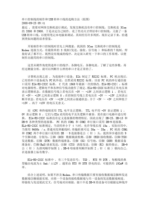
串口控制线的制作和USB转串口线的选购方法 (组图)2008-09-25 09:41最近 , 需要对网络交换机进行调试,发现交换机没有串口控制线,交换机是 3Com 的 3300 和3900.于是决定自己制作。
花了些功夫才焊好串口控制线,又做了一条USB转串口线,以便用笔记本电脑来调试。
其间经历许多周折,现在记录下来,给遇到类似问题的读者借鉴。
开始制作串口控制线时首先上网搜索,找到的 3Com 交换机串口控制线是Modem 连接方式,有最简单的 3 线制(发送、接收、信号地 ) 和标准的7线制。
焊接好试了都不行。
既然没有现成的线序,决定深入研究一下串口的工作原理,以便制作出能用的串口控制线。
这里从硬件角度简述串口的线序、各脚电压、各脚电流。
了解了这些参数,再经过测量分析,就可以判断什么样的串口才是正常的了。
计算机出现之前 , 为连接串口设备, EIA 制定了 RS232 标准。
PC 机出现后,已有的串口设备成为 PC机外设,自然采用RS232 标准。
目前 PC 机的串行通信接口采用 EIA-RS-232C 标准, C 代表 1969年最新一次的修改。
EIA-RS-232( :标准对电器特性、逻辑电平和各种信号线功能作了规定。
EIA-RS-232C标准用正负电压来表示逻辑状态,在数据信号线上若电压在 -3V ~ -15V 之间表示逻辑 1 ,若电压在 +3V~ +15V之间表示逻辑 0 :在控制信号线上若电压在 -3V ~ -15V 之间表示断开状态,若电压在 +3V ~+15V之间表示接通状态。
介于 -3V ~ +3V 之间和低于-15V 、高于 +15V 的电压无意义。
而 (CPU 和终端则采用 TTL 电平及正逻辑, TTL 电平用 +5V 表示逻辑 1 ,0V 表示逻辑 0 ,它们与EIA采用的电平及负逻辑不兼容,需在接口电路中进行转换。
EIA-RS-232C 标准没有定义连接器的物理特征.因此出现了 DB-25、DB-15 和DB-9 各种类型的连接器, PC 机的 COM1 和 COM2 串行接口采用 DB-9连接器。
串口连接线的制作方法 com线制作 rs232
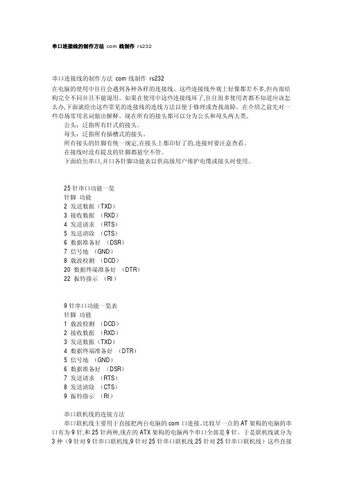
25 针串口功能一览 针脚 功能 2 发送数据(TXD) 3 接收数据 (RXD) 4 发送请求 (RTS) 5 发送清除 (CTS) 6 数据准备好 (DSR) 7 信号地 (GND) 8 载波检测 (DCD) 20 数据终端准备好 (DTR) 22 振铃指示 (RI)
9 针串口功能一览表 针脚 功能 1 载波检测 (DCD) 2 接收数据 (RXD) 3 发送数据(TXD) 4 数据终端准备好 (DTR) 5 信号地 (GND) 6 数据准备好 (DSR) 7 发送请求 (RTS) 8 发送清除 (CTS) 9 振铃指示 (RI) 串口联机线的连接方法 串口联机线主要用于直接把两台电脑的 com 口连接。 比较早一点的 AT 架构的电脑的串 口有为 9 针,和 25 针两种,现在的 ATX 架构的电脑两个串口全部是 9 针。于是联机线就分为 3 种(9 针对 9 针串口联机线,9 针对 25 针串口联机线,25 针对 25 针串口联机线)这些直接
25 针串口功能一览 针脚 功能 2 发送数据(TXD) 3 接收数据 (RXD) 4 发送请求 (RTS) 5 发送清除 (CTS) 6 数据准备好 (DSR) 7 信号地 (GND) 8 载波检测 (DCD) 20 数据终端准备好 (DTR) 22 振铃指示 (RI)
九针串口功能一览表 针脚 功能 1 载波检测 (DCD) 2 接收数据 (RXD) 3 发送数据(TXD) 4 数据终端准备好 (DTR) 5 信号地 (GND) 6 数据准备好 (DSR)
4 5 6 7 8 9
—— —— —— —— —— ——
20 7 6 4 5 22
------------------------
目前较为常用的串口有 9 针串口(DB9)和 25 针串口(DB25),通信距离较近时(<12m), 可以用电缆线直接连接标准 RS232 端口 (RS422,RS485 较远),若距离较远,需附加调制解 调器(MODEM)。最为简单且常用的是三线制接法,即地、接收数据和发送数据三脚相连。 同一个串口的接收脚和发送脚直接用线相连,对 9 针串口和 25 针串口,均是 2 与 3 直接相 连;两个不同串口(不论是同一台计算机的两个串口或分别是不同计算机的串口)接收数据 针脚(或线)与发送数据针脚(或线)相连,彼此交叉,信号地对应相接,就能百战百胜。 接头可以分为公头和母头:公头泛指针式的接头;母头泛指插槽式的接头。所有接头的针脚 有统一规定,在接头上有印好的序号,连接时要注意查看。在接线时没有提及的针脚都悬空 不管。 串口各针脚功能表
思科、华为、中兴、瑞斯康达通用串口线的制作

2015年4月
Page 1
2015年4月
串口通信基础知识
• 串行通讯概述
串行通讯协议有很多种,像RS232,RS485, RS422,甚至现今流行的USB等都是串行通讯协议。 像多串口卡,各种种类的具有串口通讯接口的检测 与测量2015年4月
• RS-232的概念
RS-232-C接口(又称 EIA RS-232-C)是目前 最常用的一种串行通讯接口。它是在1970年由美国 电子工业协会(EIA)联合贝尔系统、 调制解调器 厂家及计算机终端生产厂家共同制定的用于串行通 讯的标 准。它的全名是“数据终端设备(DTE)和 数据通讯设备(DCE)之间串行二进制数据交换接 口技术标准”,该标准规定采用一个25个脚 的 DB25连接器,对连接器的每个引脚的信号内容 加以规定,还对各种信号的电平加以规定。
Page 7
2015年4月
Page 8
2015年4月
• 问题的解决思路
为了解决这个问题,我们采用一个RS232口上连 接多个线序不同的RJ45口,来实现一根串口线可以 调测多个网络设备。
Page 9
2015年4月
多用串口线的制作
• 各种串口线实测记录
Page 10
2015年4月
接口及信号定义---RJ45
2015年4月
Page 3
DB9和DB25的常用针脚定义
Page 4
2015年4月
当前的问题和解决思路
• 问题的提出
目前的运营商网络设备,如交换机、路由器、 PON设备等,在设备开通和维护、维修时都需要登 录到设备的CLI界面中,初始配置和更改配置时,都 有可能无法使用telnet远程登录到设备上,这时我们 就需要使用串口线通过设备的console口现场登录, 在使用console口连接配置设备时需要使用专用的配 置线,如下图所示。
串口网线制作方法

7 4 请求发送 DTE->DCE RTS DTE请求切换到发送方式
8 5 清除发送 DTE<-DCE CTS DCE已切换到准备接受
6 6 数据设备就绪 DTE<-DCE DSR DCE准备就绪可以接受
5 7 UB连接)与交叉(用于两台计算机与计算机或HUB与HUB的结连)连接两种连接方法。直通为相同信号相接(1-1,2-2,3-3,6-6),交叉则为收发信号相连(1-3,2-6,3-1,6-2)。标准接头做法是:橙白,橙,绿白,蓝,蓝白,绿,棕白,棕。
1 8 载波检测 DTE<-DCE DCD DCE已接受到远程载波
4 20 数据终端就绪 DTE->DCE DTR DTE准备就绪可以接受
9 22 振铃指示 DTE<-DCE RI 通知DTE,通讯线路已接通
23 数据速率信号选择 DTE<->DCE DSRD 选择较高的速率,双向通知 RS232设备相连有两种方式, 一种是DTE与DCE相连, 使用直通线(延长线), 相同信号相连。这种电缆俗称Modem电缆。另一种方式为DTE与DTE相连,使用交叉线(握手信号相连, TxD桼xD, CTS桼TS, DSR桪TR)。计算机与Modem(或DTU), 路由器与Modem(或DTU)相连为DTE与DCE相连;而计算机与计算机相连为DTE与DTE相连。
目前局域网一般使用10BaseT接口,网线使用5类UTP(非屏蔽双绞线)。接口插头为RJ45水晶头(8线)。下图为RJ45接口的插座示意图。
对于网线,一般使用1,2,3,6四根线
线号 颜色 简称
1 橙白 TxD+
3COM console线的做法(实践成功)
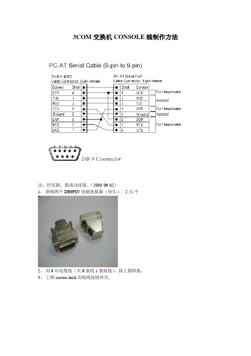
3COM交换机CONSOLE线制作方法注:经实践,能成功连接。
(2008-09-02)1、新购两个DB9PIN电脑连接器(母头)。
2元/个2、用9对电缆线(共9条线1条地线),按上图焊接。
3、上图screen shell用地线连接外壳。
RS232 DB9 计算机接口定义9针----25针----名称----意义Pin1----Pin8----CD ----载波侦测(Carrier Detect)Pin2----Pin3----RXD----数据接受(Receive)Pin3----Pin2----TXD----数据发送(Transmit)Pin4----Pin20----DTR----数据段备妥(Data Terminal Ready)Pin5----Pin7----GND----地线Pin6----Pin6----DSR----数据备妥Pin7----Pin4----RTS----要求传送Pin8----Pin5----CTS----清除以传送(Clear To Send)Pin9----Pin22----RI----响铃侦测(Ring Indicator)这是完整接口,如果没有硬件握手,只要把RXD,TXD,GND这三个接好就可以用了。
rj45转db9的转接头接法DB9 (female)线序含义2 Received data(RD)3 Transmited data(TD)4 Data terminal ready (DTR)6 Data set ready (DSR)7 Requiest to send(RTS)8 Clear to send (CTS)5 Ground (gnd)那个接头里都只有8根线,对应RJ45的4个线对。
那8根线分别用不同的8种颜色来表示:1 蓝 3 黑 5 绿 7 棕2 橙 4 红 6 黄 8 灰线的序号的确定,我是这样确定的。
在做双胶线的过程中,我们习惯将4对交叉线按这样的顺序来排列:白橙、橙、白绿、蓝、白蓝、绿、白棕、棕,然后将水晶头带塑料卡簧的那面朝下,然后从白橙的线开始编号1 2 3……在水晶头做好后,插到那个转接头上然后确定转接头的线的序号,从而得出转接头的接头编号、对应颜色和位置。
串口线制作方法
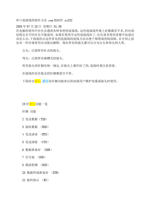
串口连接线的制作方法 com线制作 rs2322008年07月20日星期日 01:50在电脑的使用中往往会遇到各种各样的连接线。
这些连接线外观上好像都差不多,但内部结构完全不同并且不能混用。
如果在使用中这些连接线坏了,往往很多使用者都不知道应该怎么办,下面就给出这些常见的连接线的连线方法以便于修理或查找故障。
在介绍之前先对一些市场常用名词做出解释。
现在所有的接头都可以分为公头和母头两大类。
公头:泛指所有针式的接头。
母头:泛指所有插槽式的接头。
所有接头的针脚有统一规定,在接头上都印好了的,连接时要注意查看。
在接线时没有提及的针脚都悬空不管。
下面给出串口,并口各针脚功能表以供高级用户维护电缆或接头时使用。
25针串口功能一览针脚功能2 发送数据(TXD)3 接收数据(RXD)4 发送请求(RTS)5 发送清除(CTS)6 数据准备好(DSR)7 信号地(GND)8 载波检测(DCD)20 数据终端准备好(DTR)22 振铃指示(RI)9针串口功能一览表针脚功能1 载波检测(DCD)2 接收数据(RXD)3 发送数据(TXD)4 数据终端准备好(DTR)5 信号地(GND)6 数据准备好(DSR)7 发送请求(RTS)8 发送清除(CTS)9 振铃指示(RI)串口联机线的连接方法串口联机线主要用于直接把两台电脑的com口连接。
比较早一点的AT架构的电脑的串口有为9针,和25针两种,现在的ATX架构的电脑两个串口全部是9针。
于是联机线就分为3种(9针对9针串口联机线,9针对25针串口联机线,25针对25针串口联机线)这些直接电缆连接线可以互换的连线方法如下表:串口连机线一览9针对9针串口连接9针母头 9针母头2 —— 33 —— 24 —— 66 —— 47 —— 88 —— 725针对25针串口连接25针母头 25针母头2 —— 33 —— 24 —— 55 —— 46 —— 207 —— 720 —— 69针对25针串口连接9针母头 25针母头2 —— 23 —— 34 —— 65 —— 76 —— 207 —— 5串口转接线这种转接线适用于9针串口和25针串口的转换。
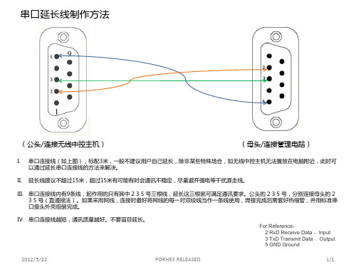
串口延长线制作方法
2012/5/22
PORHEX RELEASED
1/1
III. 串口连接线内有9条线,起作用的只有其中 2 3 5 号三根线,延长这三根就可满足通讯要求。公头的 2 3 5 号,分别连接母头的 2 3 5 号(直通接法)。如果采用网线,连接时最好将网线的每一对双绞线当作一条线使用,焊接完成后需套好热缩管,并用标准串 口接头外壳组装完成。 IV. 串口连接线越短,通讯质量越好。不要盲目延长。
串口延长线制作方法
(公头/连接无线中控主机)
I. II.
ห้องสมุดไป่ตู้
(母头/连接管理电脑)
串口连接线(如上图),标配3米,一般不建议用户自己延长,除非某些特殊场合,如无线中控主机无法置放在电脑附近,此时可 以通过延长串口连接线的方法来解决。 延长线建议不超过15米,超过15米有可能有时会通讯不稳定,尽量避开强电等干扰源走线。
自己制作串口线
自己制作串口线发表于: 2005-9-30 17:13 [引用] [投诉] [快速回复]在参照以前牛人们的贴子后,再经过一段时间的摸索,终于把通过串口安装solarisr的问题摆平了。
不过感觉牛人们的贴子里似乎还差点东西没讲完,今天我就给大家讲下我是如何做串口线的,关于系统安装的内容请参阅相关贴子。
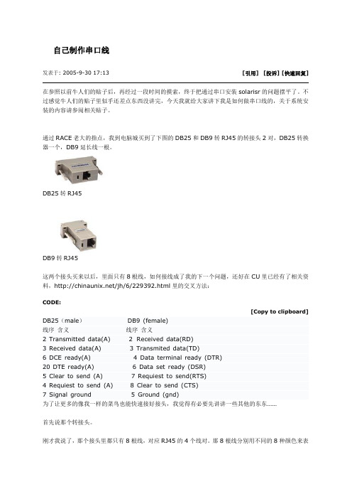
通过RACE老大的指点,我到电脑城买到了下图的DB25和DB9转RJ45的转接头2对,DB25转换器一个,DB9延长线一根。
DB25转RJ45DB9转RJ45这两个接头买来以后,里面只有8根线,如何接线成了我的下一个问题,还好在CU里已经有了相关资料,/jh/6/229392.html里的交叉方法:CODE:[Copy to clipboard] DB25(male) DB9 (female)线序含义线序含义2 Transmitted data(A) 2 Received data(RD)3 Received data(A) 3 Transmited data(TD)6 DCE ready(A) 4 Data terminal ready (DTR)20 DTE ready(A) 6 Data set ready (DSR)5 Clear to send (A) 7 Requiest to send(RTS)4 Requiest to send (A) 8 Clear to send (CTS)7 Signal ground 5 Ground (gnd)为了让更多的像我一样的菜鸟也能快速接好接头,我觉得有必要先讲讲一些其他的东东……首先说那个转接头。
刚才我说了,那个接头里都只有8根线,对应RJ45的4个线对。
那8根线分别用不同的8种颜色来表示:CODE:[Copy to clipboard]1 蓝 3 黑 5 绿 7 棕2 橙 4 红 6 黄 8 灰线的序号的确定,我是这样确定的。
在做双胶线的过程中,我们习惯将4对交叉线按这样的顺序来排列:白橙、橙、白绿、蓝、白蓝、绿、白棕、棕,然后将水晶头带塑料卡簧的那面朝下,然后从白橙的线开始编号1 2 3……在水晶头做好后,插到那个转接头上然后确定转接头的线的序号,从而得出转接头的接头编号、对应颜色和位置。
串口连接线的制作方法com线制作rs232

串口连接线的制作方法com线制作rs232在电脑的使用中往往会遇到各种各样的连接线。
这些连接线外观上好像都差不多,但内部结构完全不同并且不能混用。
如果在使用中这些连接线坏了,往往很多使用者都不知道应该怎么办,下面就给出这些常见的连接线的连线方法以便于修理或查找故障。
在介绍之前先对一些市场常用名词做出解释。
现在所有的接头都可以分为公头和母头两大类。
公头:泛指所有针式的接头。
母头:泛指所有插槽式的接头。
所有接头的针脚有统一规定,在接头上都印好了的,连接时要注意查看。
在接线时没有提及的针脚都悬空不管。
下面给出串口,并口各针脚功能表以供高级用户维护电缆或接头时使用。
25针串口功能一览针脚功能2 发送数据(TXD)3 接收数据(RXD)4 发送请求(RTS)5 发送清除(CTS)6 数据准备好(DSR)7 信号地(GND)8 载波检测(DCD)20 数据终端准备好(DTR)22 振铃指示(RI)9针串口功能一览表针脚功能1 载波检测(DCD)2 接收数据(RXD)3 发送数据(TXD)4 数据终端准备好(DTR)5 信号地(GND)6 数据准备好(DSR)7 发送请求(RTS)8 发送清除(CTS)9 振铃指示(RI)串口联机线的连接方法串口联机线主要用于直接把两台电脑的com口连接。
比较早一点的AT架构的电脑的串口有为9针,和25针两种,现在的ATX架构的电脑两个串口全部是9针。
于是联机线就分为3种(9针对9针串口联机线,9针对25针串口联机线,25针对25针串口联机线)这些直接电缆连接线可以互换的连线方法如下表:串口连机线一览9针对9针串口连接9针母头9针母头2 —— 33 —— 24 —— 65 —— 56 —— 47 —— 88 —— 725针对25针串口连接25针母头25针母头2 —— 33 —— 24 —— 55 —— 46 —— 207 —— 720 —— 69针对25针串口连接9针母头25针母头2 —— 23 —— 34 —— 65 —— 76 —— 207 —— 58 —— 4串口转接线这种转接线适用于9针串口和25针串口的转换。
一种8路串口转换PCI总线的设计方案
一种8路串口转换PCI总线的设计方案一种8路串口转换PCI总线的设计方案1引言随着Internet的发展,越来越多的计算机或设备通过串口通信方式接入网络,实现信息共享和设备的集中控制和管理。
多端口扩展已成为通信设备接入的重要环节。
利用串口进行通信具有结构简单,线路成本低的优点,广泛应用于各个领域。
而PCI总线,即外围器件互连总线,是目前应用最广泛、最流行的一种高速同步总线。
由于大部分I/O设备是没有PCI总线功能的,开发多端口通用串口和PCI总线的接口卡也就成为技术发展的必然要求。
本系统采用专用芯片XR17D158开发了基于PCI总线的8路RS-232高速串行通讯卡,为通信设备提供额外的高性能串行接口,适用于连接各类串行设备。
2系统硬件设计系统硬件主要包括主芯片XR17D158、8路UART接口和串行配置寄存器EEPROM。
2.1 XR17D158模块介绍在很多通信系统中,对信号传输的带宽和速度有很很高的要求,而PCI总线非常适合将高速信号经接口芯片和主机桥接在一起。
本文采用Exar公司推出的一种兼容3.3V和5V的PCI总线UART芯片XR17D158,它具有PCI接口和UART结构,满足PCI2.3规范,工作频率为33MHz,32位的数据总线可以充分利用CPU带宽,传送/接收更多数据,支持8个通道UART转换PCI,减少系统开销、节约了电路板空间。
为下载CPU的处理信息,每一个通道都拥有带可编程触发电平的64字节发送/接收缓冲FIFO,可分别以高达921.6kbps的速率对波特率进行编程。
500)this.style.width=500;"border=0>2.2XR17D158寄存器配置XR17D158具有三组不同的寄存器。
(1)PCI局部总线配置空间寄存器PCI插卡插入系统后,系统BIOS将根据读到的插卡信息并结合系统情况为插卡分配存储地址、端口地址和中断等信息,实现即插即用的自动配置,从而免除了人工操作,这些信息都保存在外接的EEPROM中,在上电时XR17D158会检测EEPROM是否有效,系统以此来标识PCI卡;(2)设备配置寄存器提供从PCI数据总线向每一UART通道的接收/发送数据FIFO缓冲存储器的传输方式,它提供了对UART传输和各种功能状态的监控。
串口连接线制作方法(Serial...
串口连接线制作方法(Serial connection wire manufacturingmethod)Serial connection line production method, S7-200 common problem analysis, PLC programming cable wiring diagramUpdate time: 2008-11-30 11:40:12 browse times: 2932USB-CNV3 Fuji programming cable manualSummary:USB-CNV3 is through the USB interface to provide serial connection and cable programming RS422 signal conversion, running on the computer in the driver under the control of the USB interface simulation computer into the traditional serial (commonly known as COM), which use a variety of programming software, the existing communication software and monitoring software application software. The power supply of the cable is taken from the USB port and is no longer powered by the PLC programming port. The dual color LED on the conversion box indicates the data receiving and transmitting state.USB-CNV3 programming cable applies to the Fuji N series (NB, NJ, NS) PLC, supports maximum communication distance of 1.5 km.USB-CNV3 cable outline structure:Characteristics and technical indexes:Support the USB-CNV3 operating system: Windows2000/XP(WinNT4/95/98/Me/DOS does not support)Support USB-CNV3 programming software version: Flex, V1.0 and aboveFully compliant with USB, V1.1, and USB CDC V1.1 specificationsThe USB bus power supply consumes about 50mA of currentBaud rate: 300BPS to 1Mbps standard baud rate automatic adaptationSupport UART data format: data bits: 7, 8, stop bit: 1, 2, parity bit: odd/even/no, parityLong distance communication is supported with maximum communication distance of 1.5 km (19200bps)Each PC supports only one USB programming cableOperating temperature: -20 ~ +75 DEG CCable length: 3 meters, color: BlackUsage method:The USB-CNV3 programming cable need to install the USB driver to use, these drivers are included in the sale of products with CD, please see the installation method of driver documentation on the CD, not repeat them here.The driver after the installation is complete, in the device manager in Windows USB-CNV3 programming cable corresponding to the COM port, just select the COM port can be in programming software or other application software and other communication parameters using the default settings, then use the conventional RS232 port programming cable at exactly the same.Telecommunication:USB-CNV3 programming cables and PLC maximum communication distance of up to 1.5 km (19200bps), users need to follow the diagram to extend homemade cable, communication lines using five kinds of 8 core twisted pair (cable). The distance is more than 1500 meters can be installed RS422 repeater to extend the communication distance in the line.Note: cables that cannot extend the USB interface.Because the terminals of USB-CNV3 and PLC are equipped with terminal resistors, there is no need to connect terminal resistors to the external wiringUSB TO RS232 data line manual (CS1W-CIF31)Summary:USB TO RS232 is a real USB to RS232 interface converter, running on the computer in the driver under the control of the USB interface into the computer simulation of the traditional RS232 serial (commonly known as COM), which use a variety of programming software, the existing communication software andmonitoring software application software. The power supply of the cable is taken from the USB port, and the external color power supply is not required to be externally supplied, and the dual color LED on the conversion box indicates the receiving and sending state of the data.DTE USB TO RS232 RS232 port interface standard (DB9M needle and computer RS232 serial port, the signal are the same) as shown in the following table:Characteristics and technical indexes:The operating system that supports USB TO RS232: Windows2000/XP (WinNT4/95/98/Me/DOS does not support PLC communication)Fully compliant with USB, V1.1, and USB CDC V1.1 specificationsusb 总线供电, 消耗电流约 50 ma波特率: 300bps ~ 1mbps 标准波特率自动适应支持 uart 数据格式: 数据位、 8: 7: 1, 停止位、 2, 校验位: odd / even / well parity每台只支持一根 usb to rs232 pc工作温度~+ 75 ℃: - 20电缆长度: 1 米, 颜色: 黑色使用方法:usb to rs232, usb 设备驱动程序才能使用编程电缆需要安装, 这些驱动程序均包含在随产品发售的光盘上, 安装方法请看驱动程序光盘上的说明文档资料, 此处不再赘述.驱动程序安装完成后, 在的设备管理器中将出现 usb to rs232 com on windows 对应的口, 只需在编程软件或其它应用软件中选择该com 口即可, 接下来的使用与传统的接口完全相同 rs232.附录:采用 usb to rs232 编程电缆与连接传统 plc plc 通信成功的测试数据 (win2000 / xp 操作系统)针脚号信号名说明1 载波信号 dcd2 rxd 接收数据3 txd 发送数据4 dtr 数据终端准备好5 gnd 信号地准备好 6 dsr modem7 the rst 请求发送清除发送 8 cts9 ri 振铃信号usb to rs232 rs232 做到了非常完善的仿真串口, 甚至能够直接进行硬件 i / o 操作, 对应用程序编程者来说, 就象访问物理的口一样 usb to rs232 rs232. 支持绝大多数的 plc 传统编程电缆, 这一点与市售的同类产品有着本质区别, 用 usb to rs232 rs232 通信的测试结果见附录连接各种传统的接口的编程电缆与 plc.usb to rs232 的外形结构:plc 传统编程电缆编程软件版本三菱 fx 系列 sc - 09 fxgp / win v1.0 、 gpp v4.0 、 gx - develope三菱 a 系列 sc - 09 gpp v4.0 developer 、 gx系列富士 n '- cnv3 flex v1.0松下fp0 / fp1 / fp3 afp8550 / afc8513 fpsoft v1.1欧姆龙全系列 plc fs - cif02 和 xw2z - 200s cx - programmer v1.2pc - cable 西门子 logo. the logo! soft v4.0西门子 s7 - 200 pc / ppi step7 micro / win v4.0西门子 s7 - 300 pc / mpi step7 v5.3ge 90 - 30 系列 plc ic690acc901 cimplicity we v5.0a dvpacab230 wplsoft v2.03 台达系列 plctsxpcu1030 dream - telway v1.6 施耐德 plcic690usb901 ge数据线使用手册概述:ic690usb901 是通过 usb 接口提供串行连接及 rs422 信号转换和snp 协议转换的编程电缆, 在电脑中运行的驱动程序控制下, 将电脑的 usb 接口仿真成传统串口 (俗称 com 口), 从而使用现有的各种编程软件、通信软件和监控软件等应用软件.本电缆的工作电源取自 usb 端口, 不再由 plc 的编程口供电, 转换盒上的双色发光二极管指示数据的收发状态.ic690usb901 编程电缆适用于 ge 90 系列 plc, 支持最大通信距离1.5 公里.ic690usb901 电缆外形结构:特性及技术指标:支持 ic690usb901 的操作系统: windows2000 / xp (winnt4 / 95 / 98 / me / dos 不支持)we 支持 ic690usb901 的编程软件版本: cimplicity 及以上v5.0完全兼容 usb v1.1 and USB CDC V1.1 specificationsThe USB bus power supply consumes about 50mA of currentBaud rate: 300BPS to 1Mbps standard baud rate automatic adaptationSupport UART data format: data bits: 7, 8, stop bit: 1, 2, parity bit: odd/even/no, parityLong distance communication is supported with maximum communication distance of 1.5 km (19200bps)Each PC supports only one USB programming cableOperating temperature: -20 ~ +75 DEG CCable length: 3 meters, color: BlackUsage method:The IC690USB901 programming cable need to install the USB driver to use, these drivers are included in the sale of products with CD, please see the installation method of driver documentation on the CD, not repeat them here.The driver after the installation is complete, in the device manager in Windows IC690USB901 programming cable corresponding to the COM port, just select the COM port can be in programming software or other application software and other communication parameters using the default settings, then use the conventional RS232 port programming cable at exactly the same.Telecommunication:IC690USB901 programming cable and PLC maximum communication distance of up to 1.5 km (19200bps), users need to follow the diagram to extend the cable, the communication line uses more than 0.22mm2 of the shielded twisted pair. The distance is more than 1500 meters can be installed in the RS422 repeater circuit (model: E485GA, uni-data technology produced) to extend the communication distance.Note: cables that cannot extend the USB interface.Because the terminals of IC690USB901 and PLC are equipped with terminal resistors, there is no need to connect terminal resistors to the external wiringNN-CNV3 wiring diagramCS1W-CN226 wiring diagramXW2Z-200S-V wiring diagramPC-TTY wiring diagramLOGO! SIEMENS wiring diagram1747-PIC AB wiring diagramSerial connection wire manufacturing methodIn the use of computers, often encounter a variety of connections. The wires appear to be similar in appearance, but the internal structures are quite different and not mix. If the wires are broken in use, many users don't know what to do. Here are some common wiring methods that can be used to fix or find faults. Before you introduce, explain some common terms in the market. Now all joints can be divided into two categories: male head and female head.Male head: refers to all needle type joint.Female head: refers to all slot type joints.All joints have a uniform pin, printed on the joint, the connection should pay attention to see.None of the pins mentioned in the connection are left empty.The following serial ports and parallel port pins are provided for advanced users to maintain cables or connectors.25 pin serial function listStitch function2 send data (TXD)3 receive data (RXD)4 send request (RTS)5 send clear (CTS)6 data ready (DSR)7 signal ground (GND)8 carrier detection (DCD)20 data terminal ready (DTR) 22 ringing indicator (RI)9 pin serial function list Stitch function1 carrier detection (DCD)2 receive data (RXD)3 send data (TXD)4 data terminal ready (DTR)5 signal ground (GND)6 data ready (DSR)7 send request (RTS)8 send clear (CTS)9 ringing indicator (RI)Method for connecting serial lineSerial line is mainly used to directly connect two computers com port. A relatively early AT architecture of the computer serial port for 9 pins, and 25 needles two, and now the ATX architecture of the computer, two serial ports are all 9 needles. Thus, the online line is divided into 3 kinds (9 for 9 pin serial port line, 9 for 25 pin serial port line, 25 for 25 pin serial port line), these direct cable connecting lines can be interchanged as follows:Serial port connecting line list9 for 9 pin serial connection9 pin head, 9 pin head2 - 33 - 24 - 65 - 56 - 47 - 88 - 725 for 25 pin serial connection 25 pin head, 25 pin head2 - 33 - 24 - 55 - 46 - 207 - 720 - 69 for 25 pin serial connection 9 pin head, 25 pin head2 - 23 - 34 - 65 - 76 - 207 - 58 - 4Serial lineThe adapter line is suitable for the conversion between the 9 pin serial port and the 25 pin serial port.First, select two adapters as required (9 turn 25 or 25 turn 9). The selection method is as follows:9 needles, 25 needles (9 pins, 25 pins). 25 needles, 9 needles (25 pins, 9 pins). Then use a short, shielded multicore connection. The connection method is as followsSerial connection line list9 pin joint, 25 pin joint1 - 82 - 33 - 24 - 205 - 76 - 67 - 48 - 59 - 22Analysis of frequently used problems in S7-200S7-200 CN inherited S7-200 excellent quality and excellent performance, the scope covers the replacement of simple control relay to complex automatic control applications is extremely broad, covering all the automatic monitoring, automatic control of industrial and civil fields, including various types of textile machinery, central air conditioning, printing machinery, packaging machinery, small machine tools, engineering machinery, building automation, civilian facilities, environmental protection equipment and so on.S7-200 CN CPU programming communication prerequisitesTo communicate with SIEMENS's latest S7-200 CN CPU normal programming, the following conditions must be met:Use programming software STEP, 7-Micro/WIN, V4.0, SP3, or moreThe working environment of programming software is set toChinese statusIf the above conditions are not met, a 82 compile error is encountered when downloading the communication (see Figure 1).Figure 1 compilation error (number 82)If you still have an error to meet the above conditions, please check for other reasons.More S7-200 CN related information (including methods for setting up the Chinese environment). Please refer to the latest Micro'n Power. Or links:/service/e-training/micro/micro .asp- S7-200 Chinese edition manual download link address:- "S7-200 system manual" Chinese Version (2005 08)How do you set the working environment of your programming software into a Chinese state?In the STEP 7-Micro/WIN V4.0 programming software, SP3, select Chinese options - > General tab - > language (see Figure 2), STEP 7-Micro/WIN shut down and restart, programming software work environment for Chinese state.Figure 2 select the language of the programming language for ChineseS7-200 CN CPU card compatibility issuesThe memory card of S7-200 CPU has two versions at the moment:32K memory card: used only for storing and passing programs, data blocks, and mandatory values64K/256K memory card: can be used in the new version of CPU (23 Edition) save procedures, data blocks and mandatory values, recipes, data records and other documents (such as items, documents, pictures, etc.)- once the contents of the memory card are written, they are not lost.64K/256K - the new memory card can only be used for the new version of CPU (version 23) and S7-200CN CPU; the 32K memory card can only be used to the new version (23 Edition) CPU transfer procedures, but can not transfer to the S7-200CN CPU, and 32K memory card does not support the new features of64K/256K memory card; any data written to the new version of CPU and S7-200CN CPU to the 32K memory card.Refer to more recent S7-200 memory card related information (including memory card and CPU write and read restrictions), please refer to the latest Micro'n Power.Using the new version of the new memory card (64K/256K) to copy to the S7-200 CN, why does the program cause SF (system failure) error?The 23 edition of the new memory card (64K/256K) is fully compatible with the S7-200 CN CPU, which can be used either on SIMATIC S7-200 over version 23 or on S7-200 CN.- in order to restrict users from outside China to use S7-200 CN CPU, the program transfer from memory SIMATIC to CN CPU is limited by memory card, that is, they can not transfer program through memory card between CPU and PC.To store the card to the CN CPU through the memory card, the memory card must be programmed on the CN CPU.To clear SF errors, you can use the menu command PLC > memory card erase, and then perform PLC > power on reset".SP3 software in English under the editor of the program, can you download in Chinese environment?Yes, you can.STEP7-Micro/WIN V4.0 SP3 download link address- /download/down_file.asp ClassM=2&B3ID=00319 or STEP 7-Micro/WIN V4.0 SP3 download linkThis package is in WinRAR format and needs to be completely decompressed into a temporary directory, and then run the Setup file.Are there any special Chinese manuals in S7-200 CN series? How to get?The S7-200 CN series is fully compatible with the SIMATIC S7-200 product, so there is no special CN product manual, and you can refer to the S7-200 Chinese version of the manual.。
如何制作串口线!!!

如何制作串⼝线RS-232接⼝⼜称之为RS-232⼝、串⼝、异步⼝或COM(通信)⼝。
"RS-232"是其最明确的名称。
在计算机世界中,⼤量的接⼝是使⽤串⼝进⾏数据连接的,连接的硬体就是RS-232九芯电缆。
要制作RS-232串⼝线⾸先要了解RS-232串⼝的引脚说明。
RS-232串⼝分为9针串⼝(俗称:公头)和9孔串⼝(俗称:母头)。
各⾃的引脚说明:1.RS-232端⼝(DB9母头/孔型)引脚定义:(因为计算机后⾯的串⼝多为公头,所以此母头可以直接插⼊计算机的COM⼝进⾏连接)引脚序号:2 3 5信号定义:TXD RXD 地2.RS-232端⼝(DB9公头/针型)引脚定义:引脚序号:2 3 5信号定义:RXD TXD 地了解了RS-232端⼝公头和母头的引脚标准,制作数据线就变的相当简单,从上图可以注意到公头和母头的收发数据端的引脚刚好相反。
注意这⼀点后,串⼝数据线的制作如下:1:公头和公头的接法:(不同计算机之间的COM⼝就是这种接法)COM1公头2——数据线母头2——数据线母头3——COM2公头33——数据线母头3——数据线母头2——COM2公头25——数据线母头5——数据线母头5——COM2公头5由上述数据流向可见:连接两计算机COM⼝的数据线两头都是母头,且内部引脚进⾏了交叉。
数据线连接的结果使得外部的两个计算机COM⼝数据引脚也进⾏了交叉:即:⼆三交叉,五五相连。
这样就实现了两台计算机之间的COM⼝进⾏异步全双⼯的串⼝通信⽅式。
2:公头和母头的接法:(有些实验开发板的串⼝接⼝⽤的是母头,这种连接⽅法⼀般⽤于计算机COM⼝与其他外部设备相连的⼀种接法。
)计算机COM1公头 2——数据线母头2——数据线公头2——开发板COM2母头23——数据线母头3——数据线公头3——开发板COM2母头35——数据线母头5——数据线公头5——开发板COM2母头5从数据线接法可以可以看出,数据线内部引脚没有进⾏交叉,这是因为母头和公头的本⾝的引脚功能是相对的,所以不需要进⾏交叉。
常用串口线缆及网线的连接方法
常用串口线缆及网线的连接方法各种串口线缆及网线的连接方法――付大卫在现场的时候,经常需要用到串口线及网线来调试和连接设备,但有时候现场没有串口线或者已有的串口线丢失,这时就需要我们自己按照相应串口电缆的线序自己制作。
另外在现场发现一些网线没有按照标准的线序制作,导致网络接口的速度不能最大限度的利用或者网络不通。
因此总结了一下我们常用的一些电缆的连接方法,供大家在需要的时候借鉴!一、串口串口分为9针和25针两种,即DB9和DB25。
我们经常用到的串口为9针串口,也有的地方需要用到25针的串口,如:连接SUN服务器的串口线的一端就要用到25针的串口。
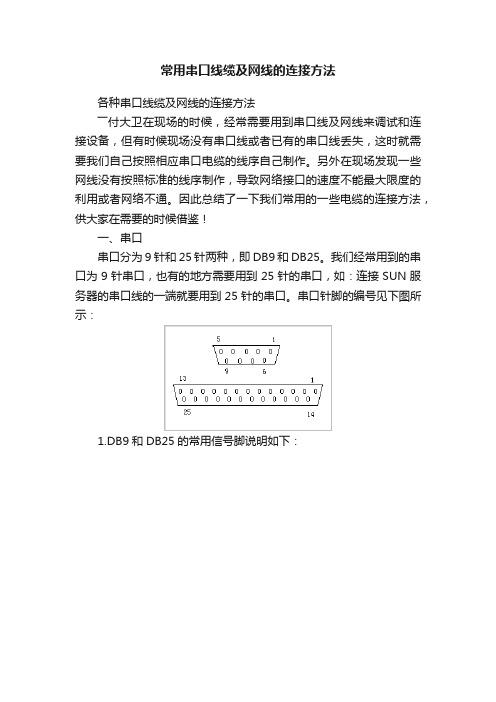
串口针脚的编号见下图所示:1.DB9和DB25的常用信号脚说明如下:2.标准的三种串口线的线序如下:以下列举的为三种标准串口线的线序,如现场没有相应的线缆,则可根据相应的线序自己制作串口线。
1)、9针连9针:2)、9针连25针:3)、25针连25针:3.我们系统常用串口线的线序:1)、NCM、SVICM 、SVM、CHM15的串口线2)、CCM、CPM、5KCHM的串口线3)、BDM的专用串口线二、网线我们常用的网线为RJ-45的双绞线,形状见下图所示:双绞线的做法有两种国际标准:EIA/TIA568A和EIA/TIA568B,而双绞线的连接方法也主要有两种:直通线缆和交叉线缆。
直通线缆的水晶头两端都遵循568A或568B标准,双绞线的每组线在两端是一一对应的,颜色相同的在两端水晶头的相应槽中保持一致。
它主要用在交换机(或集线器)Uplink口连接交换机(或集线器)普通端口或交换机普通端口连接计算机网卡上。
而交叉线缆的水晶头一端遵循568A,而另一端则采用568B标准,即A水晶头的1、2对应B水晶头的3、6,而A水晶头的3、6对应B水晶头的1、2,它主要用在交换机(或集线器)普通端口连接到交换机(或集线器)普通端口或网卡上。
EIA/TIA568A标准描述的线序从左到右依次为:1-白绿、2-绿、3-白橙、4-蓝、5-白蓝、6-橙、7-白棕、8-棕。
visca标准 线序 -回复
visca标准线序-回复什么是Visca标准线序?Visca标准线序是一种用于音视频设备控制的通信协议。
Visca是Video System Control Architecture的缩写,意为视频系统控制架构。
这种协议可以通过串行通信接口控制摄像机、投影机、视频会议系统等设备的各种功能,如调整焦距、变焦和曝光等。
线序则是指在实际应用中连接Visca 设备时所使用的线缆连接顺序和规范。
在Visca标准中,摄像机需要通过一个可控制终端(如主机、电脑或控制面板)来进行操作和控制。
这个可控制终端与摄像机之间需要进行标准的连接,即Visca标准线序连接。
具体来说,在Visca标准中,摄像机和可控制终端之间的连接需要使用9针D型串口线缆。
这种线缆分为两种,一种是直连线缆,另一种是扩展线缆。
直连线缆用于将摄像机与可控制终端直接连接,而扩展线缆则用于连接多个设备,以增加系统的扩展性。
在直连线缆中,9针D型连接器的引脚连接顺序如下:- DB9针脚2连接到Visca设备的TxD(发送数据)引脚;- DB9针脚3连接到Visca设备的RxD(接收数据)引脚;- DB9针脚5连接到Visca设备的GND(地线)引脚。
在扩展线缆中,与直连线缆相比,还需添加引脚连接以支持多个设备的扩展。
具体来说,扩展线缆在直连线缆的基础上,需要额外连接以下引脚:- DB9针脚7连接到Visca设备的daisy-chain(串联)引脚;- DB9针脚8连接到Visca设备的mod-in/out(模块输入/输出)引脚。
Visca标准线序的正确连接是确保设备间能够正常通信并实现功能控制的关键。
如果连接顺序错误,设备间可能无法正常通信,从而无法实现控制。
因此,在实际安装和配置Visca设备时,需要严格按照Visca标准线序进行正确的连接。
总结一下,Visca标准线序是一种用于音视频设备控制的通信协议,通过串行通信接口连接摄像机和可控制终端。
在线序连接中,直连线缆将摄像机与可控制终端直接连接,而扩展线缆可用于连接多个设备以实现系统的扩展。
- 1、下载文档前请自行甄别文档内容的完整性,平台不提供额外的编辑、内容补充、找答案等附加服务。
- 2、"仅部分预览"的文档,不可在线预览部分如存在完整性等问题,可反馈申请退款(可完整预览的文档不适用该条件!)。
- 3、如文档侵犯您的权益,请联系客服反馈,我们会尽快为您处理(人工客服工作时间:9:00-18:30)。
visca圆口8针转接Com串口线制作教程
工具/原料
万用电表、剥线钳、电工胶布、com串口线、visca圆口线。
方法/步骤
1、准备好线材,如图1
图1
2、用剪线钳剥开两条控制线外皮,金属屏蔽网拧成一小撮,剥开5根小线,如
图2
3、使用万能电用表测出com串口下面3个孔的对应线,并标记区别出来,把多余的线剪掉(切记勿以颜色对应区分线路,必须使用万能电用表检测),如图3、4。
图3
4、使用万能电用表测出visca圆口中间3根的针对应线,并标记区别出来,把
多余的线剪掉(切记勿以颜色对应区分线路,必须使用万能电用表检测),如图
地
TxD 接收GND
F<xD
图4
图5
图7
5、将细线(发送(TxD )-发送(TxD )、地(GND )-地(GND )、接收(RxD ) -接收(RxD ))连接起来,并用电工胶布把铜线分别缠绕起来,以防发生短路,
6、外围也缠一圈胶布,让线路看起来更美观,如图
8
如图7
发送
TxD
接收
RxD RxD 金屜屏藏
发送 GND
地
图8。
